

Page 1

Vane Axial Heater
Installation and Operation
Model #:
Owner ’s Manual
PNEG-012
Date: 10-30-09
PNEG-012
Page 2

Heater Check List
1. All wire connections
2. Spark plug gap 0.125
3. Pipe train tightness and gas leaks
4. Flame sensor tight
5. Fuse in place, extra fuse provided
6. Time delay reset
7. Indicator light
8. Pressure gauge
9. Regulator adjusted
10. Shut off valve operates correctly
11. Vapor high-limit
12. Unit cycles ON to OFF
13. Heat rise even across transition
14. Unit cycles high to low (high-low only)
15. Modulating valve holds temperature within 1° (mod units only).
16. All decals and serial number tag
17. Aesthetic appearance
18. Manual
Tester Signature:___________________________
Date: ____________________________________
2 PNEG-012 Vane Axial Heater
Page 3

Table of Contents
Contents
Chapter 1 Safety .................................................................................................................................................. 4
Safety Guidelines ............................................................................................................................... 4
Introduction ........................................................................................................................................ 5
Chapter 2 Safety Decals ..................................................................................................................................... 6
Roof Damage Warning and Disclaimer .............................................................................................. 6
Heater Access Door Decals ............................................................................................................... 7
Control Box Decals ....................................................................................................................... ... .. 8
Chapter 3 Specifications .................................................................................................................................... 9
Heater Specifications ......................................................................................................................... 9
Chapter 4 Installation ....................................................................................................................................... 10
Fuel Connection ............................................................................................................................... 10
Liquid Propane Models ....................................................................................... .... ... ... ................... 10
Propane Vapor Models .................................................................................................................... 10
Natural Gas Models ......................................................................................................................... 10
Standard Heater Electrical Installation ................................... .......................................... ... .... ......... 10
Standard Heater - Second Heater Installation .................................................... .... ... ... ... ... .... ... ... ... 12
Deluxe Heater Electrical Installation ................................................................................................ 13
Deluxe Heater - Second Heater Installation ..................................................................................... 14
Bin Configuration .............................................................................................................................. 15
Transition High-Limit Installation ...................................................................................................... 15
Plenum Thermostat Mounting .......................................................................................................... 16
Heater Setup .................................................................................................................................... 17
Chapter 5 Operation ......................................................................................................................................... 18
Operating Temperature Table .......................... ... ... ... .... ... .......................................... ... ... ................ 18
Cycling Heater Operation ................................................................................................................. 18
Time Delay Operation - Standard Heater.......................................................................................... 19
High-Low Heater Operation ............................................. ... ... .... ... ... ................................................ 20
Modulating Valve Operation ............................................................................................................. 21
Adjusting the Vaporizer .................................................................................................................... 22
BTUs per Gauge Pressure (PSI) - Propane Models (Approximate) .............................. ................... 23
BTUs per Gauge Pressure (PSI) - Natural Gas Models (Approximate) ..................................... ... ... 24
Chapter 6 Service .............................................................................................................................................. 25
Chapter 7 Troubleshooting - Standard Heater................................................................................................ 26
Chapter 8 Wiring Diagrams .............................................................................................................................. 27
Standard Heater Wiring .................................................................................................................... 27
Standard Heater Schematic ............................................................................................................. 28
Deluxe Heater .............. ... .... ... ... ... .... .......................................... ...................................................... 29
Chapter 9 Parts List .......................................................................................................................................... 30
Standard Heater Control Box Parts ..................... ... ... .... ... ... ... .... ... ... ... ... .... ...................................... 30
Deluxe Heater Control Box Parts ..................................................................................................... 32
18" Gas Heater Parts .......................... ... ... ... .... ... ... .......................................................................... 33
24", 26" and 28" Gas Heater Parts ................................................................................................... 34
18" Vapor/NG Pipe Train Assembly .......... .......................................... ... .... ... ... ... .... ... ... ... ... .... ... ...... 36
24", 26" and 28" LP Pipe Train Assembly ........................................................................................ 37
24", 26" and 28" LP High-Low Pipe Train Assembly ........................................................................ 38
24", 26" and 28" LP Modulating Pipe Train Assembly ..................................................................... 39
24", 26" and 28" Vapor/NG Pipe Train Assembly ............................................................................ 40
24", 26" and 28" Vapor/NG High-Low Pipe Train Assembly ............................................................ 41
24", 26" and 28" Vapor/NG Modulating Pipe Train Assembly .......................................................... 42
LP Supply Pipe Train Assembly ....................................................................................................... 43
Chapter 10 Warranty ......................................................................................................................................... 45
PNEG-012 Vane Axial Heater 3
Page 4
1. Safety
Safety Guidelines
This manual contains information that is important for you, the owner/operator, to know and understand.
This information relates to protecting personal safety and preventing equipment problems. It is the
responsibility of the owner/operator to inform anyone operating or working in the area of this equipment
of these safety guidelines. To help you recognize this information, we use the symbols that are defined
below. Please read the manual and pay attention to these sections. Failure to read this manual and its
safety instructions is a misuse of the equipment and may lead to serious injury or death.
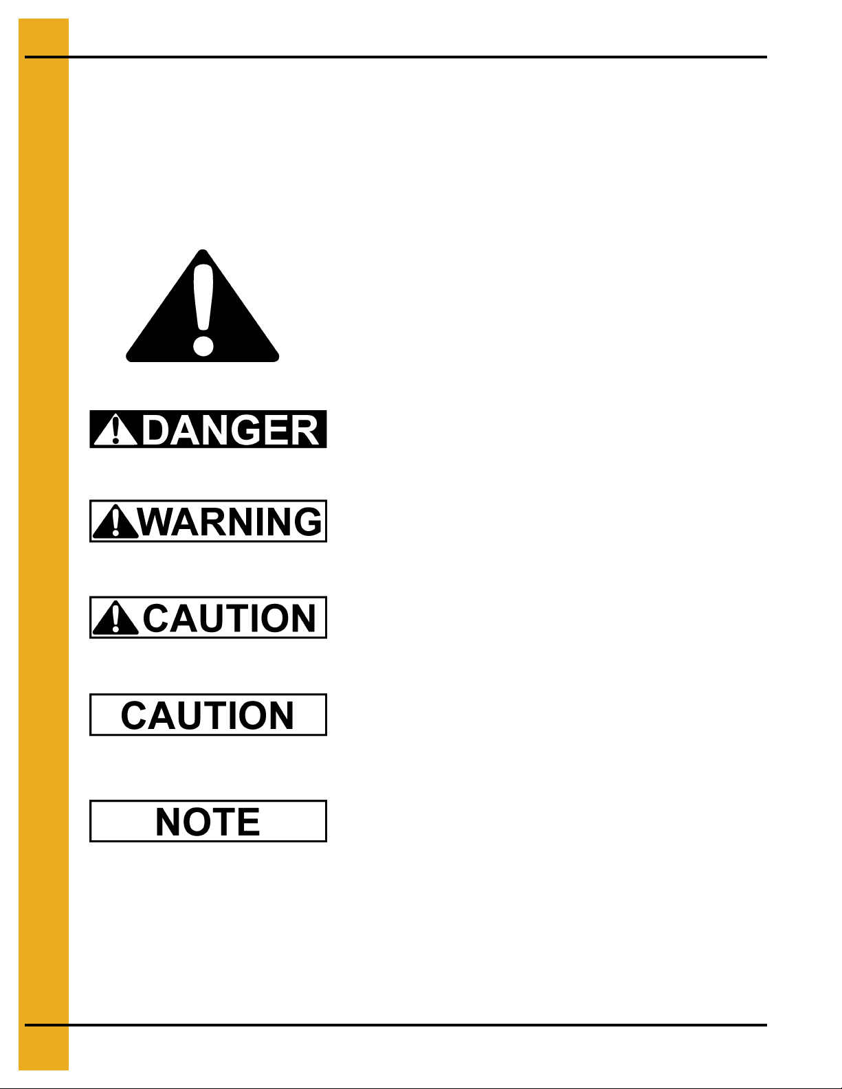
This is the safety alert symbol. It is used to alert you to
potential personal injury hazards. Obey all safety
messages that follow this symbol to avoid possible
injury or death.
DANGER indicates an imminently hazardous situation
which, if not avoided, will result in death or serious injury.
WARNING indicates a potentially hazardous situation
which, if not avoided, could result in death or serious injury.
CAUTION indicates a potentially hazardous situation
which, if not avoided, may result in minor or moderate injury.
CAUTION used without the safety alert symbol indicates a
potentially hazardous situation which, if not avoided, may
result in property damage.
NOTE indicates information about the equipment that you
should pay special attention.
4 PNEG-012 Vane Axial Heater
Page 5

1. Safety
Introduction
Thank you for choosing a GSI product. It is designed to give excellent performance and service for
many years.
This manual describes the operation of the Deluxe and Standard Vane Axial Heater: VHD and VHS. It
is designed for low to medium temperature grain conditioning, and is ideal for the aeration of rice,
popcorn or other select grains. It is available in both propane vapor and natural gas models.
Our foremost concern is your safety and the safety of others associated with this equipment. We want
to keep you as a customer. This manual is to help you understand safe operating p rocedures and some
problems which may be encountered by the operator and other personnel.
As owner and/or operator, it is your responsibility to know what requirements, hazards and precautions
exist, and to inform all personnel associated with the equipment or in the area. Safety precautions may
be required from the personnel. Avoid any alterations to the equipment. Such alterations may produce
a very dangerous situation where SERIOUS INJURY or DEATH may occur.
This equipment shall be installed in accordance with the current installation codes and applicable
regulations which should be carefully followed in all cases. Authorities having jurisdiction should be
consulted before installations are made.
PNEG-012 Vane Axial Heater 5
Page 6
2. Safety Decals
If a decal is damaged or missing contact:
GSI Decals
1004 E. Illinois St.
Assumption, IL. 62510
Phone: 1-217-226-4421
A free replacement will be sent to you.
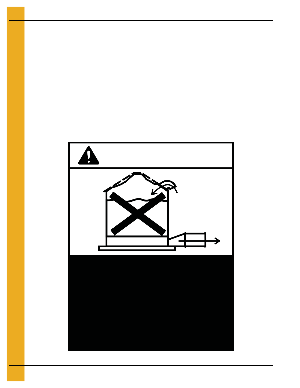
Roof Damage Warning and Disclaimer
The manufacturer does not warrant any roof damage caused by excessive vacuum or internal
pressure from fans or other air moving systems. Adequate ventilation and/or “makeup air”
devices should be provided for all powered air handling systems. The manufacturer does not
recommend the use of downward flow systems (suction). Severe roof damage can result from
any blockage of air passages. Running fans during high humidity/cold weather conditions can
cause air exhaust or intake ports to freeze.
CAUTION!
Excessive vacuum (or pressure) may
damage roof. Use positive aeration
system. Make sure all roof vents are
open and unobstructed. Start roof
fans when supply fans are started.
Do not operate when conditions exist
that may cause roof vent icing.
DC-969
6 PNEG-012 Vane Axial Heater
Page 7
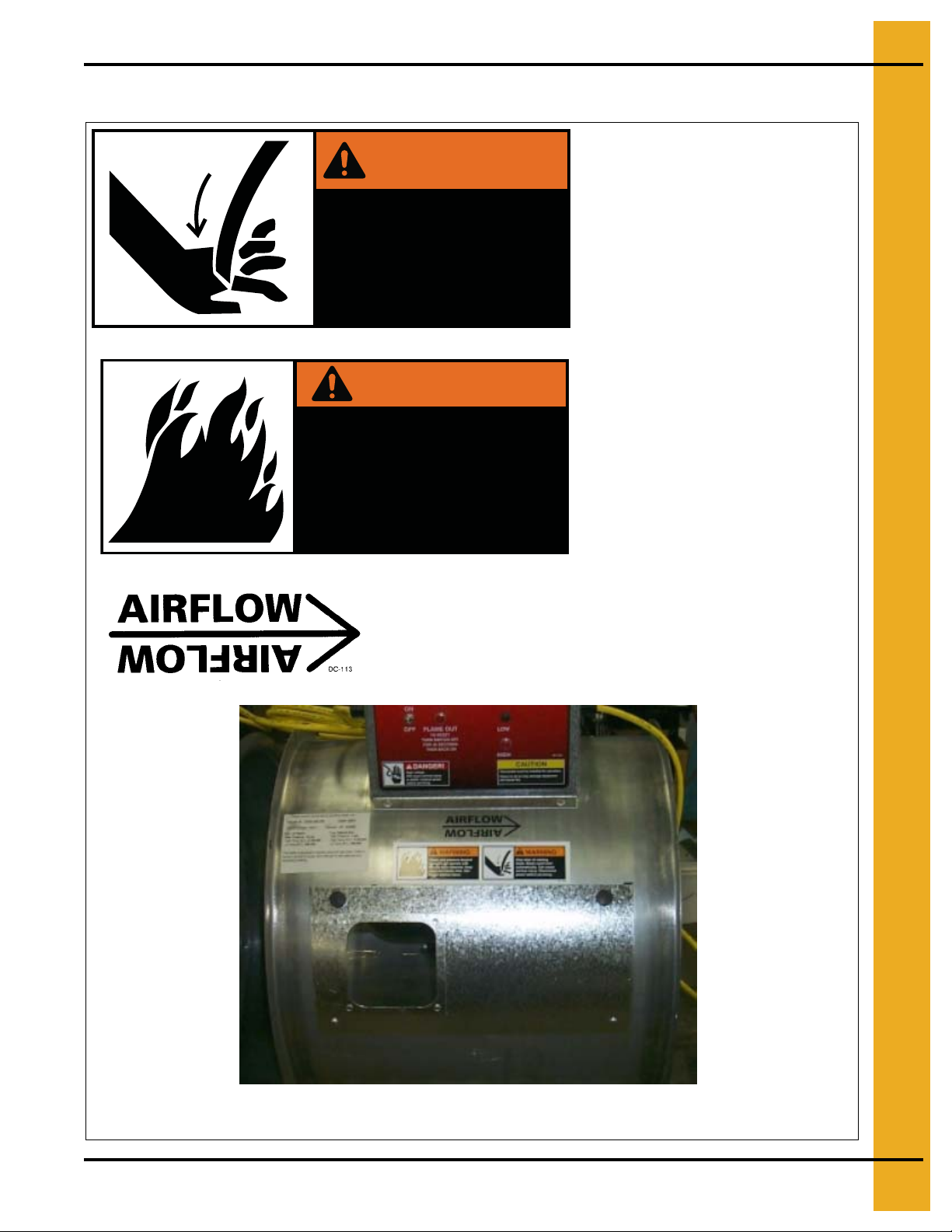
Heater Access Door Decals
WARNING
2. Safety Decals
DC-1225
Stay clear of rotating
blade. Blade could start
automatically. Can cause
serious injury. Disconnect
power before servicing.
DC-1225
WARNING
Flame and pressure beyond
door can cause serious
injury. Do not operate with
service door removed. Keep
head and hands clear.
DC-1227
DC-113
Size: 4.75" x 1.625"
Located above access door on
heater housing.
Size: 4.875" x 2.25"
Located above access door on
heater housing.
See Note below.
DC-1227
Size: 4.875" x 2.25"
Located above access door on
heater housing.
See Note below.
NOTE: May be substituted with DC-1559 combination decals.
PNEG-012 Vane Axial Heater 7
Page 8
2. Safety Decals
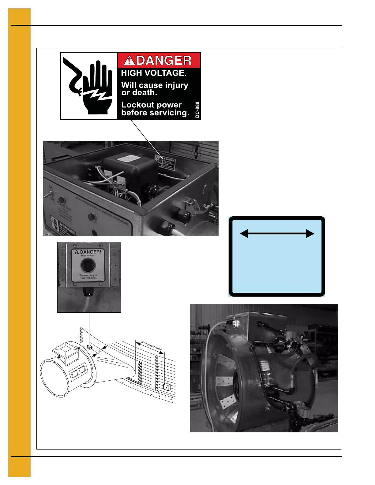
Control Box Decals
DC-889
Size: 2.813" x 1.375"
Located in control box on side
opposite switches.
Similar decal is incorporated into the
control panel decal.
WARMER
VAPORIZER ADJUSTMENT
VAPORIZER COIL SHOULD BE ADJUSTED
SO VAPOR PIPE TRAIN IS WARM
(100°F-125°F) TO THE TOUCH
COLDER
DC-535
8 PNEG-012 Vane Axial Heater
Page 9
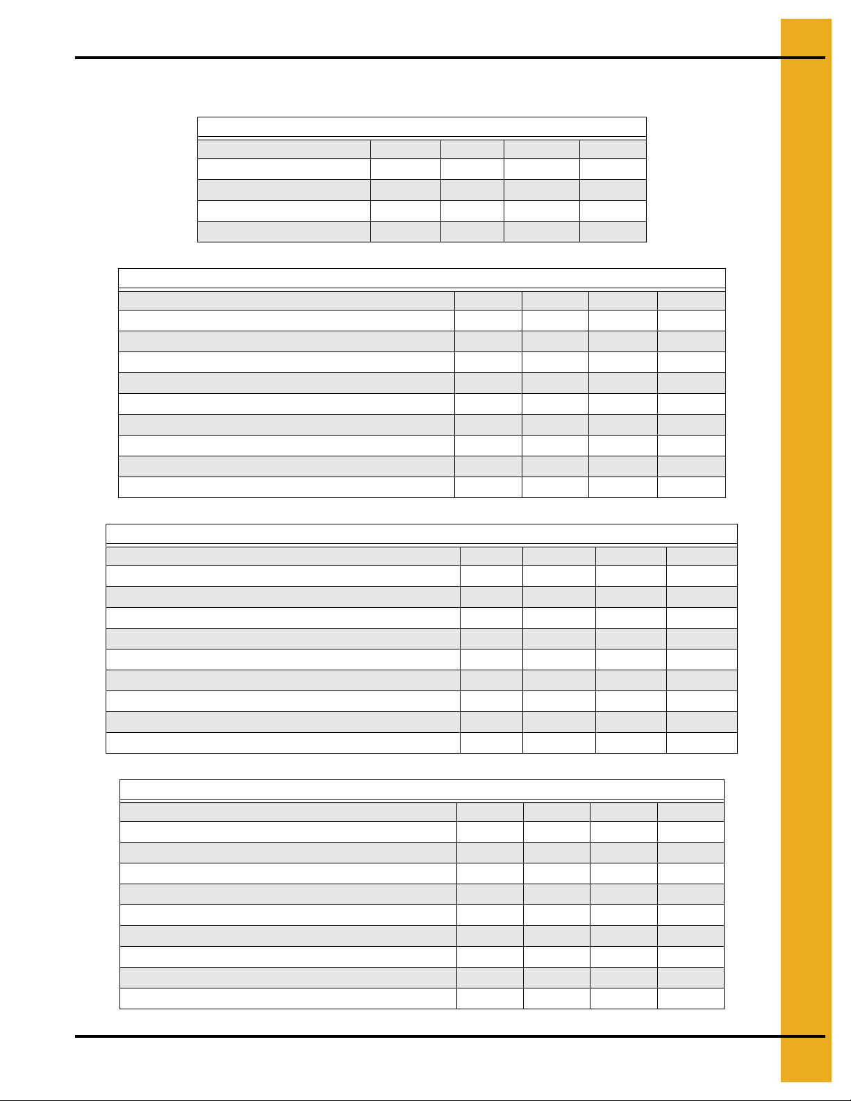
Heater Specifications
Fan Model 18" 24" 26" 28"
Inside Diameter (inches) 18-5/16" 24-1/4" 26-5/16" 28-1/8"
Bolt Circle Diameter (inches) 19-7/16" 25-3/4" 27-15/16" 29-5/8"
Length (inches) 22 22-1/2" 22-1/4" 25-1/4"
Weight (pounds) 83 129 133 136
Fan Model 18" 24" 26" 28"
Minimum Operating Pressure (PSI) 2 2 2 2
Maximum Operating Pressure (PSI) 15 10 15 20
Minimum Supply Line (inches) 1/2" 3/4" 3/4" 3/4"
High Temperature Orifice (inches) 11/64" 7/32" 7/32" 7/32"
High Temperature BTU Rating at Maximum Pressure 1,400,000 2,100,000 2,700,000 3,000,000
High Temperature Fuel Flow at Maximum Pressure (CFH) 585 877 1128 1253
Low Temperature Orifice (inches) 3/32" 3/32" 3/32" 3/32"
Low Temperature BTU Rating at Maximum Pressure 400,000 350,000 400,000 500,000
Low Temperature Fuel Flow at Maximum Pressure (CFH) 167 146 167 208
3. Specifications
Common Measurements
Vapor Models
Liquid Models
Fan Model 18" 24" 26" 28"
Minimum Operating Pressure (PSI) N/A 2 2 2
Maximum Operating Pressure (PSI) N/A 10 15 20
Minimum Supply Line (inches) N/A 3/8" 3/8" 3/8"
High Temperature Orifice (inches) N/A 7/32" 7/32" 7/32"
High Temperature BTU Rating at Maximum Pressure N/A 2,100,000 2,700,000 3,000,000
High Temperature Fuel Flow at Maximum Pressure (CFH) N/A 23 30 34
Low Temperature Orifice (inches) N/A 3/32" 3/32" 3/32"
Low Temperature BTU Rating at Maximum Pressure N/A 350,000 400,000 500,000
Low Temperature Fuel Flow at Maximum Pressure (CFH) N/A 4 4.5 5.5
Natural Gas
Fan Model 18" 24" 26" 28"
Minimum Operating Pressure (PSI) 1 1 1 1
Maximum Operating Pressure (PSI) 7 4 5 7
Minimum Supply Line (inches) 3/4" 1" 1-1/4" 1-1/4"
High Temperature Orifice (inches) 17/64" 3/8" 3/8" 3/8"
High Temperature BTU Rating at Maximum Pressure 1,400,000 2,100,000 2,700,000 3,000,000
High Temperature Fuel Flow at Maximum Pressure (CFH) 1400 2100 2700 3000
Low Temperature Orifice (inches) 11/64" 7/32" 7/32" 7/32"
Low Temperature BTU Rating at Maximum Pressure 400,000 350,000 400,000 500,000
Low Temperature Fuel Flow at Maximum Pressure (CFH) 400 350 400 500
PNEG-012 Vane Axial Heater 9
Page 10
4. Installation
Fuel Connection
Do not use propane tanks which have previously been used for ammonia unless
they have been purged according to procedures of the national LP association.
Investigate to be sure that the fuel supply system complies with all local codes for
LP gas installations.
Liquid Propane Models
1. LP models are designed to run on liquid propane, with liquid draw from the propane tank. Avoid
using propane supply tanks that have been use for vapor draw for long periods of time. Wh en using
liquid draw systems any moisture that may be present in tank or lines may freeze when system is
used in cold weather. To avoid this, the usual precaution is to purge the system with methanol.
2. Run proper size line
service person inspect installation to be sure everything is installed according to local codes
and ordinances.
3. After installation is complete check all connections for leaks. Use liquid detergent or comparable
substance. Wear rubber gloves and eye protection. Avoid contact with liquid propane. DO NOT
USE FLAME FOR LEAK TESTING.
(See Specifications on Page 9)
to pipe train on heater. Have a qualified gas
Propane Vapor Models
1. Propane vapor models are designed to run directly off of supply tank or from a separate
external vaporizer.
2. Run proper size line
service person inspect installation to be sure everything is installed according to local codes
and ordinances.
3. After installation is complete check all connections for leaks.
(See Specifications on Page 9)
to pipe train on heater. Have a qualified gas
Natural Gas Models
1. Natural gas models are similar to vapor models, but have a larger orifice to accommodate lower
pressure, sometimes found with natural gas.
2. Run proper size line (See Specifications on Page 9) to pipe train on heater. Have a qualified gas
service person inspect installation to be sure everything is installed according to local codes
and ordinances.
3. After installation is complete check all connections for leaks.
Standard Heater Electrical Installation
Always disconnect and lock out power before working on or around heater.
Standard electrical safety practices and codes should be used when working with a heater. Refe r to the
National Electric Code Standard Handbook by the National Fire Protection Association. A qualified
electrician should make all wiring installations.
10 PNEG-012 Vane Axial Heater
Page 11
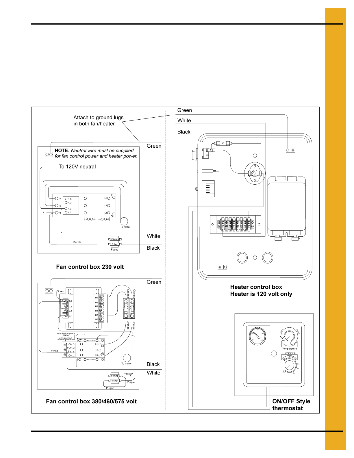
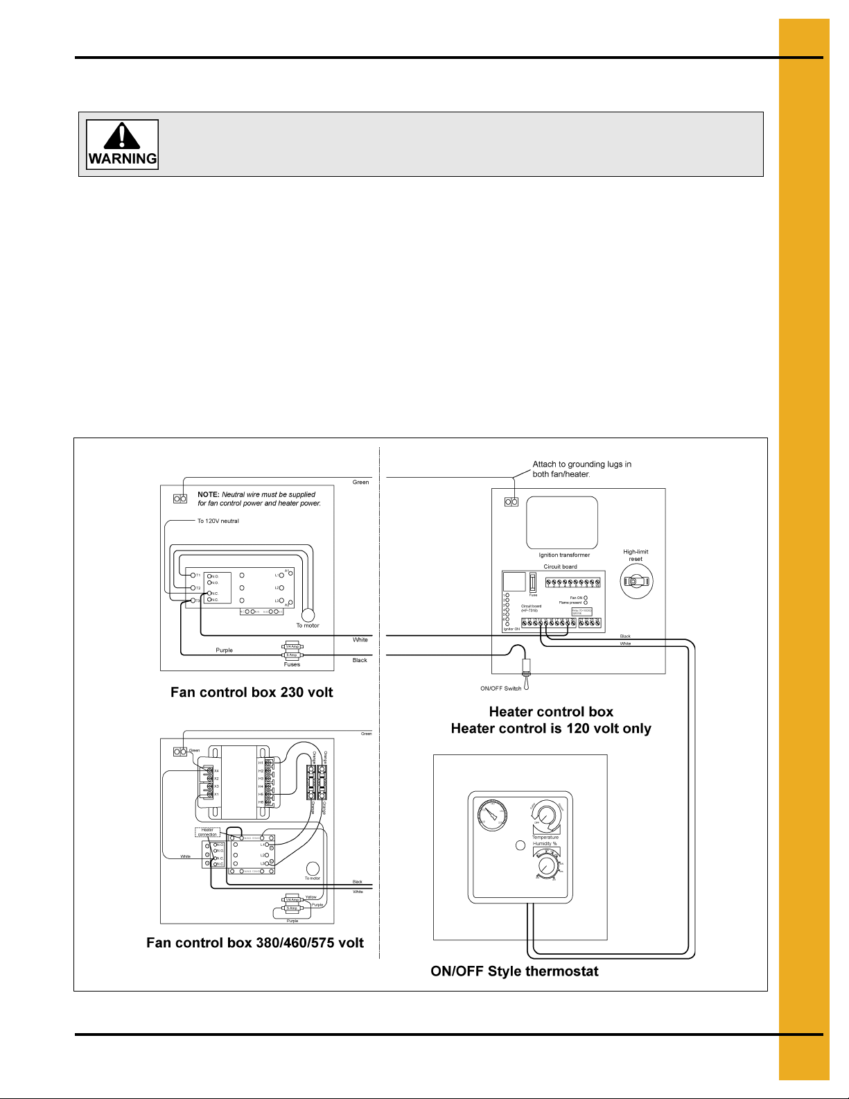
IMPORTANT: Heater must be interlocked with fan for safe operation.
Heater Power Connection
1. Connect power cord to fan control box.
2. Make field connections in fan box as shown in Figure 4A.
3. Connect deluxe thermostat control as shown in Figure 4A.
IMPORTANT: Thermostat must be installed for safe operation.
4. Installation
Figure 4A Heater Wiring Installation on a Fan Unit
PNEG-012 Vane Axial Heater 11
Page 12
4. Installation
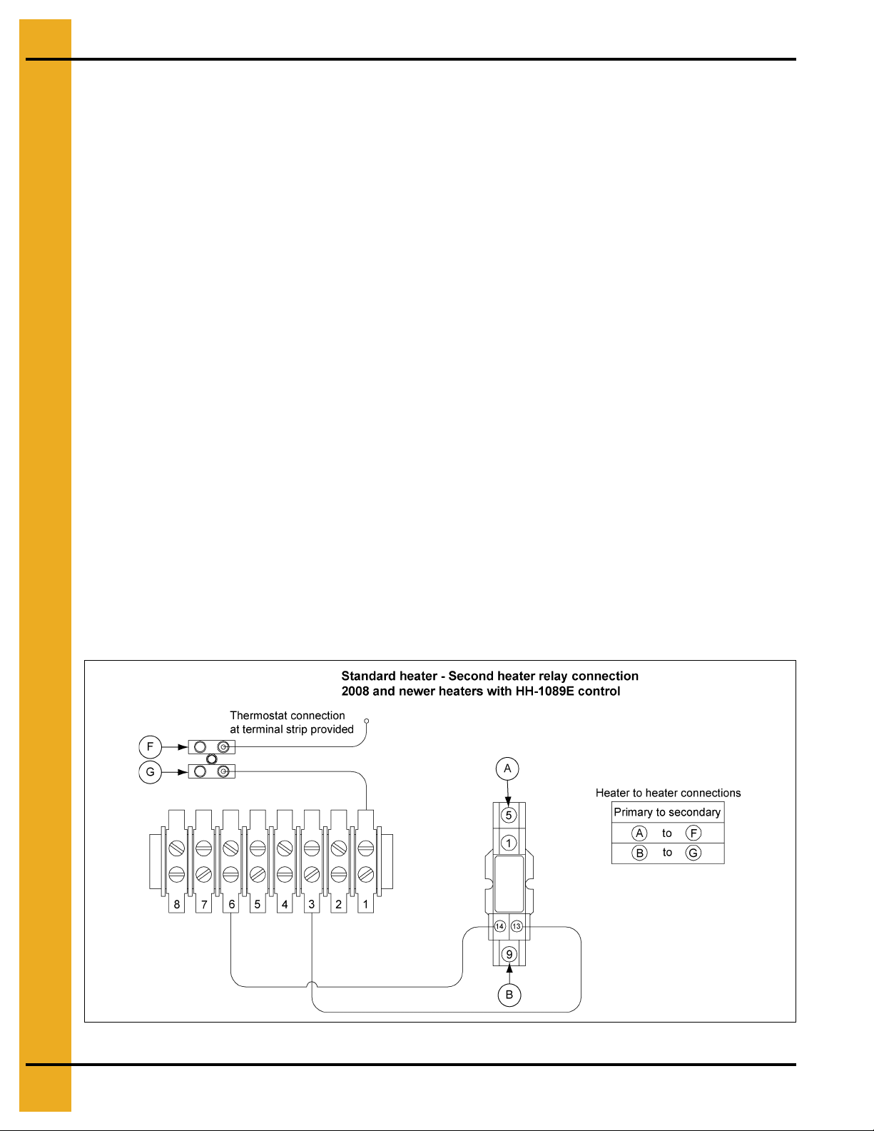
Standard Heater - Second Heater Installation
Two (2) standard heaters may be connected to one grain drying system and wired so they cycle together.
One of the heaters should have a thermostat connected to it as per the installation instructions. That
heater will be referred to as the primary. The other heater (without the thermostat) will be referred to as
the secondary.
1. Install relay base (TD-100283) in primary heater control box.
2. Connect wire between terminal 13 on relay base to terminal 6 on terminal strip in primary heater.
3. Connect wire between terminal 14 on relay base to terminal 3 on terminal strip in primary heater.
4. Run two (2) wires (18 gauge) between primary and secondary heater.
5. Connect wires to terminals 5 and 9 (points A and B) on relay base in primary heater.
6. Connect wire from terminal 9 in primary to terminal 5 (point F) in secondary unit.
7. Connect wire from terminal 5 in primary to terminal 8 (point G) in secondary unit.
8. Install relay (TD-100282) in relay base.
Follow these additional steps for HIGH-LOW units.
1. Install relay base (TD-100283) in master heater control box.
2. Connect wire between terminal 13 (point E) on relay base to green wire from HIGH-LOW thermostat
in master unit. Do not disconnect other wires from green wire 3. Connect wire between terminal 14
on relay base to terminal 14 on other relay base in master heater.
3. Run two (2) wires (18 gauge) between master and slave heater.
4. Connect wires to terminals 5 and 9 (points C and D) on relay base in master heater.
5. Connect wire from terminal 9 in master to terminal 6 (point H) in slave unit.
6. Connect wire from terminal 5 in master to cycle solenoid and red light in slave unit. Do not connect
wire to side of cycle solenoid and light that are connected to terminal.
Figure 4B Standard Heater - Second Heater Relay Connection
12 PNEG-012 Vane Axial Heater
Page 13
4. Installation
Deluxe Heater Electrical Installation
Always disconnect and lock out power before working on or around heater.
Standard electrical safety practices and codes should be used when working with a heater. Refer to the
National Electric Code Standard Handbook by the National Fire Protection Association. A qualified
electrician should make all wiring installations.
IMPORTANT: Heater must be interlocked with fan for safe operation.
Heater Power Connection
1. Connect power cord to fan control box.
2. Make field connections in fan box as shown in Figure 4C.
3. Connect deluxe thermostat control as shown in Figure 4C.
IMPORTANT: Thermostat must be installed for safe operation.
Figure 4C Illustration of deluxe Vane Axial Heater wiring installation on a fan unit.
PNEG-012 Vane Axial Heater 13
Page 14
4. Installation
Deluxe Heater - Second Heater Installation
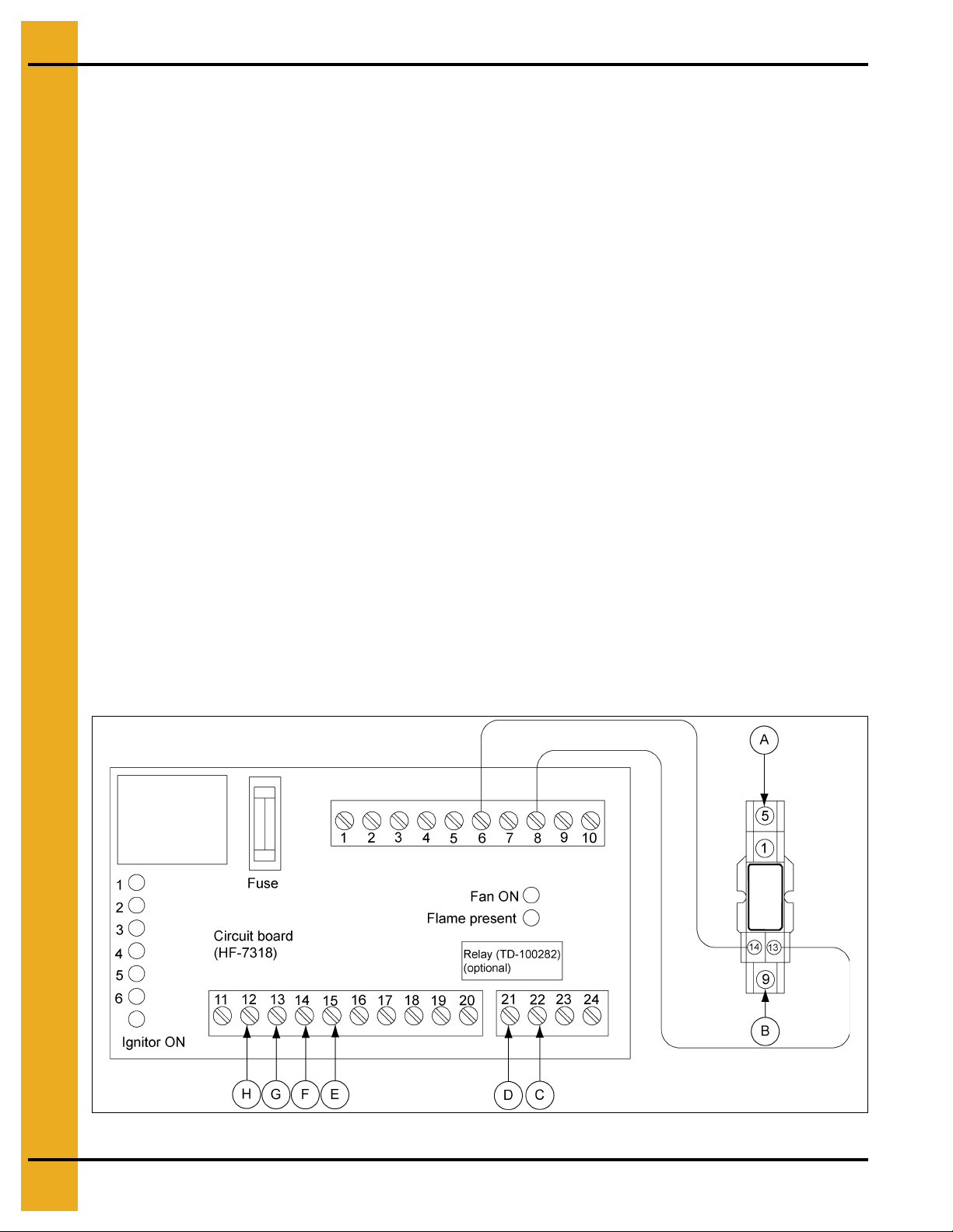
For Deluxe Units Using HF-7318 Control Board
Two (2) deluxe heaters may be connected to one grain drying system and wired so they cycle together.
One of the heaters should have a thermostat connected to it as per the installation instructions. That
heater will be referred to as the master. The other heater (without the thermostat) will be referred to as
the slave.
Installation for ON/OFF Units
1. Install relay base (TD-100283) in master heater control box.
2. Connect wire between terminal 6 on circuit board and terminal 14 on relay base in master heater.
3. Connect wire between terminal 13 on relay base and terminal 8 on circuit board in master heater.
4. Run two (2) wires (18 gauge) between master and slave heaters.
5. Connect wires to terminal 5 and 9 (points A and B) on relay base in master heater.
6. Connect wire from terminal 9 in master to terminal 14 (point F) in slave unit.
7. Connect wire from terminal 5 in master to terminal 15 (point E) in slave unit.
8. Install relay (TD-100282) in relay base.
Additional Steps for High-Low Units
1. Run two (2) wires (18 gauge) between master and slave unit.
2. Connect wires to terminals 21 and 22 (points C and D) on circuit board in main heater.
3. Connect wire from terminal 21 in master to terminal 12 (point H) in slave unit.
4. Connect wire from terminal 22 in master to terminal 13 (point G) in slave unit.
5. Install relay (TD-100282) in relay base.
Figure 4D The Control Board (HF-7318)
14 PNEG-012 Vane Axial Heater
Page 15

Bin Configuration
4. Installation
Figure 4E
IMPORTANT: When mounting two (2) heate rs on a bin it is imperative that they be situated as shown in
Figure 4E. Plenum thermostat must be to the right of master heater and master heater
must be to the right of slave heater.
Transition High-Limit Installation
1. Mark location on transition one (1) foot up from the bottom (entrance collar) and centered in
the transition.
2. Drill or knock out 7/8" diameter hole on marked location.
3. Install transition high-limit using supplied self-drilling screws.
Figure 4F The transition connecting the Vane Axial Heater to the bin with the plenum sensor in place.
PNEG-012 Vane Axial Heater 15
Page 16

4. Installation
Plenum Thermostat Mounting
The plenum thermostat must be ordered separately from the heater unit.
1. Follow installation instructions provided with the thermostat assembly.
2. Position the housing so that the bolt flanges are vertical, and the cord exits the housing from the
bottom. Mark position.
3. Use 6 (4.00") or 8 (2.66") self-drilling screws to mount the housing to the bin sidewall. DO NOT
TIGHTEN COMPLETELY. Insert corrugation seal into gap between housing and sidewall.
Tighten screws.
4. Caulk between the housing and the sidewall to seal.
Figure 4G Plenum thermostat mounted on bin wall.
IMPORTANT: Thermostat must be installed for safe operation.
Figure 4H Side view of thermostat showing corrugation seal.
16 PNEG-012 Vane Axial Heater
Page 17

4. Installation
Heater Orifice Setup
The factory has set the orifices size for propane, high temperature and natural gas, low temperature.
1. Determine the type of gas to be used: Propane or natural gas.
2. Determine the operating temperature ranges to be used: High or low. Refer to tables on Page 23
and Page 24.
3. For natural gas high temperature applications remove reducer bushing with pressure gauge and
remove 7/32" primary orifice from system. Replace reducer bushing and check connections
for leaks. For natural gas high temperature configuration there is no primary orifice in the system.
Refer to Fuel - Temperature Table below.
4. For propane low temperature applications remove reducer bushing with pressure gauge and
replace the supplied 7/32" primary orifice with a 3/32" orifice supplied in control box. Replace
reducer bushing and check connections for leaks. Refer to Fuel - Temperature Table below.
Figure 4I
Fuel - Temperature
Fuel
Natural Gas Remove primary orifice completely.
Propane
No modifications required.
Standard with 7/32" orifice.
High Low
T emperature
No modifications required.
Standard with 7/32" orifice.
Replace primary orifice with 3/32"
orifice supplied in control box.
Make sure the configuration matches the appropriate application in the
Fuel - Temperature Table above. Propane has a higher BTU content than
natural gas. Do not remove 3/8" secondary orifice. Excessive heat rise due to
improper orifice sizing or removing the 3/8" secondary orifice will damage
grain or cause fire.
PNEG-012 Vane Axial Heater 17
Page 18

5. Operation
Operating Temperature Table
IMPORTANT: The below table is not intended as a drying guide. It should be used as a reference
for setting maximum plenum temperature for safe operation.
Do not exceed plenum temperatures listed in table below.
High Temperature
Batch Dry
No Stirring
120° 140° 160°
100° 100° Not Recommended
110° 120° Not Recommended
High Temperature
with Stirring
Corn
Rice
Beans
and
Wheat
Low T e mpe r ature
Batch
5°-20° above
Ambient
Temperature
5°-10° above
Ambient
Temperature
5°-20° above
Ambient
Temperature
Cycling Heater Operation
1. Thermostat must be wired into heater control box for heater to operate.
2. Open all manual shut off valves to heater unit.
3. Start fan. This will supply power to heater.
4. Turn thermostat dial to its highest setting.
Continuous
Flow (Recirculating)
5. Turn toggle switch ON.
6. Heater should now be lit. If not check to see that all gas is ON.
7. Watch thermometer on plenum and when it reaches desired temperature turn thermostat back
slowly until heater cycles OFF.
8. Gas pressure should be adjusted so burner is ON 75% of the time.
9. Watch plenum temperature as burner goes through a few cycles, to be sure that it is
operating properly.
18 PNEG-012 Vane Axial Heater
Page 19

5. Operation
Time Delay Operation - Standard Heater
HH-1089E Time Delay Reset Operation
The electronic time delay will indicate the operating condition of the heater through the LED light shown
in Figure 5A. This light should be on the exterior control panel of the heater when the unit is installed
correctly. This light is very helpful in identifying the status of the flame probe (open or closed) and will
indicate a lock out condition.
Start-up
The light should be ON when the ON/OFF switch is set to ON. This indicates that the heater h as power
and the flame probe is closed. The gas solenoid should open and ignitor should spark. The light will
remain on until the flame probe opens. The light should go OFF if flame is established within the
30 second trial for ignition.
If flame is not present or the probe does not open, then the light will blink continuously after the 30 second
time period. It will blink continuously until the heater is reset.
Turn power OFF for 10 second to reset a lock out condition. The light will stop blinking after the
10 second time period. The heater cannot be restarted if the light is blinking continuously.
Thermostat Cycle
The heater thermostat will cycle the gas solenoid OFF when temperature is reached. The flame probe
should cool to a closed condition when this occurs. The thermostat will also cool to a closed condition
with a drop in plenum temperature. The thermostat closure is a call for heat and the normal start-up for
the time delay begins again.
A condition can occur where the thermostat can call for heat before the flame probe cools to a closed
condition. The light ON the time delay will flash once at thermostat closure and remain OFF until the
flame probe closes again. The heater will not operate until this “closed” condition of both switches
is achieved.
Light Status Indication
Light
ON
OFF
BLINKING
Flame probe is closed.
Time delay in 30 second trial for
ignition period.
Normal operation with flame present.
Flame probe open. Thermostat closed.
Normal operation with no flame present.
Flame probe open. Thermostat open.
Lock out: Flame probe closed after
30 second.
To reset: Turn power OFF. Wait
10 second. Turn power ON.
Figure 5A Flame Probe Light ON Time Delay
PNEG-012 Vane Axial Heater 19
Page 20

5. Operation
High-Low Heater Operation
1. High-Limit and cycling thermostat must be wired into heater control box for heater to operate.
2. Open all manual shut off valves to heater unit.
3. Start fan. This will supply power to heater.
4. Turn thermostat dial to its highest setting.
5. Turn toggle switch ON. Both lights should illuminate indicating power to the control circuit.
6. Heater should now be lit. If not check to see that all gas is ON.
7. Open adjustment screw on solenoid valve all the way.
8. Turn thermostat dial back slowly until heater cycles to low flame.
9. Adjust screw on solenoid valve so that low flame pressure is at desired setting. (As low as possible.)
10. Turn thermostat dial to desired setting and wait for bin plenum to come up to temperature. Heat er
should cycle to low flame after a few minute.
11. If heater does not cycle to low flame increase high flame gas pressure by adjusting the regulator.
12. High flame should be adjusted so the heater cycles 75% of the time. Low flame should be adjusted
so there is enough flame for unit to keep operating.
13. Watch as burner goes through a few cycles, to be sure that it is operating properly back to
high flame.
Figure 5B
20 PNEG-012 Vane Axial Heater
Page 21

5. Operation
Modulating Valve Operation
1. The modulating valve regulates gas flow through the heater based on sensing unit in the plenum,
and maintains a constant drying air temperature.
2. The sensing bulb of the modulating valve should be mounted through the bin wall with the side
reading “top” up. The bulb reacts to temperature. It changes the amount of gas (increase or
decrease), burning warmer or cooler depending on the position of the valve SET POINT. If the bulb
is cooler than it was at the SET POINT, the bulb senses the cooler temperature and opens the valve
further so more heat is applied to the drying air. If the bulb is warmer than it was at th e SET POINT,
the valve closes further and reduces the temperature until the air is at the valve SET POINT.
3. It is important that the pressure regulator be set high enough to allow the modulating valve to deliver
enough gas to maintain the plenum temperature necessary. The regulator is normally factory set
at 15 PSI (propane units). To set the regulator, run the heater and turn the modulating valve
T-handle in. This gets full line pressure to the burner. Then adjust regulator to read 15 PSI
(depending on the plenum temperature needed).
4. Turn the fan/heater ON. To set the modulating valve, turn the T-handle out (counterclockwise) until
loose and wait a few minute for the plenum temperature to equalize. When the temperature under
the bin has equalized, gradually turn T-handle in (clockwise) about 1/2 turn at a time. Wait until
temperature under bin has equalized as before. If temperature under bin is less than the desired
temperature, continue turning T-handle in, increasing gas flow and waiting for plenum temperature
to equalize until the desired temperature is the stable temperature of the plenum. If temperature
under bin is the same 10 minute after you last made any adjustments to the T-handle you can be
certain that the temperature under the bin is the SET POINT of the valve. 1 Turn of the T-handle
equals approximately 7°F of temperature.
5. The valve will now keep the plenum temperature at the set point regardless o f ambien t co nditions
as long as humidistat or thermostat do not shut down the heater. A bypass orifice is used to
maintain a small flame when outside temperature is near or above the set point of the valve. The
bypass ensures steady application of heat at minimum gas flow operation. Bypass orifice will only
operate correctly if pressure regulator is set correctly.
6. To observe how the modulating valve increases the efficiency of bin drying, check the gas pressure
of the unit in the morning and compare to the pressure read mid-afternoon. If the ambient (outside)
temperature is significantly greater later in the day (as normal), the gas pressure will be less. Since
less heat is required to maintain the same temperature in the plenum, the modulating valve will
have reduced the amount of gas used by the heater.
PNEG-012 Vane Axial Heater 21
Page 22

5. Operation
Adjusting the Vaporizer
1. Vaporizer should be adjusted so the vapor pipe train runs warm to the touch (100°F-120°F).
2. Loosen 5/16" bolt on adjustment bracket.
3. Swivel vaporizer away from flame if running too hot, closer to flame if too cold.
4. Move vaporizer only 1" at a time and allow a few minute for temperature to equalize.
5. Tighten 5/16" bolt and watch heater run for several minute to verify adjustment.
Figure 5C
Adjusting the vaporizer coil on a liquid propane model. The Figure 5C shows the setting in, and
the Figure 5D shows the coil out.
Figure 5D
22 PNEG-012 Vane Axial Heater
Page 23

5. Operation
BTUs per Gauge Pressure (PSI) - Propane Models (Approximate)
High Temperature
Diameter
2 4 6 8 101214161820
24", 26" and 28" 892,353 1,218,775 1,496,555 1,734,425 1,940,412 2,121,835 2,285,304 2,436,723 2,581,288 2,723,487
Operating Pressure (PSI)
Low Temperature
Diameter
2468101214161820
All Models 163,902 223,857 274,877 318,568 356,402 389,725 419,750 447,561 474,114 500,232
Operating Pressure (PSI)
Gauge Pressure (PSI) Required to Maintain Temperatures (Approximate)
(Shaded Areas Represent Low Temperature Settings)
Fan
Model
3 HP-18"
5 HP-24"
7 HP-24"
10 HP-24"
15 HP-26"
15 HP-28"
Static
Pressure
1"
2"
3"
1"
2"
3"
1"23457912
2"2234568
3"1123345
4"
1"235681214
2"23457912
3"1234567
4"
5"
1"3469121420
2"2357101216
3"23457912
4"1233567
5"
1" 4 7 10 14 20 25 30
2" 3 6 8 12162025
3" 3 5 7 10141820
4"2458101416
5"23457912
60 80 100 120 140 160 180
10234578
6 1022345
2 3 5 6 8 10 14
10111223
6 10 141112
2 3 4 6 8 10 14
5 9 14 20 1 1 2
12 2011233
4 7 12 15 20 1 1
14112234
Heat Rise °F
PNEG-012 Vane Axial Heater 23
Page 24

5. Operation
BTUs per Gauge Pressure (PSI) - Natural Gas Models (Approximate)
High Temperature
Diameter
1234567
18" 659,337 831,044 989,238 1,135,039 1,269,526 1,393,734 1,508,661
24", 26" and 28" 1,314,110 1,656,337 1,971,631 2,262,224 2,530,266 2,777,823 3,006,882
Operating Pressure (PSI)
Low Temperature
Diameter
1234567
18" 276,054 347,946 414,179 475,224 531,531 583,536 631,654
24", 26" and 28" 447,163 563,615 670,902 769,785 860,993 945,231 1,023,175
Operating Pressure (PSI)
Gauge Pressure (PSI) Required to Maintain Temperatures (Approximate)
(Shaded Areas Represent Low Temperature Settings)
Fan
Model
3 HP-18"
5 HP-24"
7 HP-24"
10 HP-24"
15 HP-26"
15 HP-28"
Static
Pressure
1"
2"
3"
1"
2"
3"
1"
2"
3"
4"
1"
2"
3"
4"
5"
1"
2"
3"
4"
5"
1"23457912
2"1234679
3"
4"
5"
60 80 100 120 140 160 180
3 412234
2 2 3 4122
1 1 2 2 2 3 3
1 2 2 3 4 5 6
1 1 1 2 2 3 3
1 1 1 1 1 1 1
3 522334
2 4 62233
2 3 4 5 622
1 1 1 2 2 2 3
4 623345
3 522334
3 4 52223
1 2 2 3 4 5 6
1 1 1 1 2 2 2
5223467
4223456
3 522334
2 4 52333
1 2 3 4 5 62
6234568
4223456
3 522335
Heat Rise °F
24 PNEG-012 Vane Axial Heater
Page 25

6. Service
All heaters are constructed of durable weather-resistant materials, so a minimum amount of service
should be required. Before the unit is started for the first time each season there are a few items that
need to be checked out. All damaged parts should be repaired or replaced.
1. Disconnect and lock out power to fan/heater. Open control box lid and inspect all components for
moisture, vibration or rodent damage. Inspect and tighten all loose terminal connectio ns. Re place
any damaged wiring.
2. Remove burner orifice tube and inspect for dirt or foreign material. Clean out if necessary.
3. Inspect holes in burner ring for possible corrosion or plugging with dirt or rust. Clean if necessary.
4. Be sure primary air inlet screen is intact and clean for proper burn.
5. Check perforated ring on natural gas models to be sure it is clean and no holes are plugged.
6. Inspect flame probe and ignitor and adjust or replace if necessary.
Always disconnect and lock out power before working on or around heater.
PNEG-012 Vane Axial Heater 25
Page 26

7. Troubleshooting - Standard Heater
Trouble Probable Cause Check-out Procedure
Burner will not fire. No gas
pressure on gauge.
No ignition spark.
Burner will not fire. No gas
pressure on gauge. Constant
ignition spark.
Burner will not fire. Gas pressure
on gauge. No ignition spark.
1. Heater not wired.
2. Fan not running. 2. Fan contactor must be energized for heater to run.
3. Blown fuse. 3. Visually check fuse.
4. Bad ON/OFF switch.
5. Housing high-limit switch. 5. Reset switch. Check for power on terminals 1 and 8.
6. Thermostat open.
7. Flame probe open.
1. Electronic time delay. 1. Time delay is in lock out or not receiving power.
2. Gas supply.
1. Loose wire.
2. Ignitor/spark plug.
3. Ignition transformer/wire.
1. Visually check fan control box to see if wires
are connected.
4. Check ON/OFF switch contact block for proper
installation and continuity. Check for power on
terminals 1 and 8.
6. Plenum temperature above set point temperature or
open circuit.
7. Remove wires from flame probe and check with ohm
meter. Probe should be closed when cold.
2. Make sure all valves are open to heater and gas tank is
not empty.
1. Check for power on terminals 4 and 7. Look for loose
wires or incorrect wiring.
2. Turn gas OFF to heater. Check gap on ignitor. Check
porcelain for any sign of cracks. Remove plug wire from
spark plug/ignitor. Carefully holding wire by insulation.
Try to get an arc between end of wire and heater
housing (or other wire using two (2) pole transformer).
3. Turn gas OFF to heater. If no spark present after
checking ignitor, remove wire from ignition transformer.
Check for spark at ignition transformer with an insulated
screwdriver. Spark should jump a minimum 1/4" gap.
Replace transformer if no spark is established, replace
the ignition wires.
1. Check for gas at burner. If no gas, remove pipe train and
check orifice and burner ring for blockage.
2. Check to be sure flame probe is in good condition and is
located in flame. Flame probe contacts should open
when probe gets hot.
4. See that flame burns continuous and is not intermittent.
On ring burners be sure flame burns completely
around ring.
5. Have tank and lines checked by a qualified gas
service man.
Burner will not fire or fires for
30 second and locks out. Gas
pressure on gauge. Spark is ON.
1. Plugged orifice.
2. Flame probe.
3. Incorrect supply voltage. 3. Voltage to heater must be 110V AC.
4. Regulator set too low.
5. Moisture in fuel.
26 PNEG-012 Vane Axial Heater
Page 27

Standard Heater Wiring
8. Wiring Diagrams
PNEG-012 Vane Axial Heater 27
Page 28

8. Wiring Diagrams
Standard Heater Schematic
28 PNEG-012 Vane Axial Heater
Page 29

Deluxe Heater
8. Wiring Diagrams
PNEG-012 Vane Axial Heater 29
Page 30

9. Parts List
Standard Heater Control Box Parts
30 PNEG-012 Vane Axial Heater
Page 31

9. Parts List
Standard Heater Control Box Parts List
Ref # Part # Description Qty
1 HF-7698 Backing Plate - Heater 1
2 HF-8111 Control Box - Standard 1
3 069-1376-8 Control Box Lid - Poly Blank 1
4 090-1699-9 Rivet, 1/8" Diameter x 0.775" Long ARSM 0.501-0.625 Grip Range 4
5 90-0009 Lamp, 120V Amber 1
6 D03-0696 Control Box Latch 2
7 DC-1878 Decal, Heater Standard w/ Reset 1
8 E240-1107 Terminal Strip 12 Position 10A 12 Gauge 4
9 FH-1058-1 Fuse Block - Double 1/4" x 1-1/4" 1
10 FH-1059 Fuse, 5 Amp 250V Fast Acting 2
11 FH-1309 Lock Nut 1/2" #401 ARL. 4
12 FH-1310 Cord Connector, Heyco 4
13 E160-1137 Lug Ground, ADR6 2
14 HF-7697 Terminal Strip Bracket 1
15 HF-7696 Switch, 2 Position Selector: Lever 1
16 HH-1089E Electronic Time Delay Reset 1
17 HH-1487 Transformer 1 Pole Ignition 1
18 TFH-2013 Terminal Block 8 Pole 1
19 THH-4020 High-Limit Switch 200° 1
20 HF-7454 High-Limit Box Body 1
21 HF-7455 High-Limit Box Lid 1
22 HF-7439 High-Limit Switch 250° 1
23 048-1018-0 Hole Plug - BP - 7/8" 1
N/S D02-0039 Wire Tie Anchor 1
N/S D03-0247 Wire Tie 5" Panduit Plate 1-1/2 mm 1
PNEG-012 Vane Axial Heater 31
Page 32

9. Parts List
Deluxe Heater Control Box Parts
Deluxe Heater Control Box Parts List
Ref # Part # Description
1 069-1376-8 Control Box Lid
2 HH-1487 Transformer 1 Pole Ignition
3 HF-7318 Circuit Board Assembly
4 THH-4020 High-Limit Switch 200°
5 D03-0696 Control Box Latch
6 HF-7211 Snap Track
7 HF-7718 Control Box - Deluxe
8 DC-1695 Decal, Heater Deluxe w/ Reset
9 TFH-2021 Red Light (110V)
10 HF-7696 Tog g l e Switch
11 HF-7455 High-Limit Box Lid
12 HF-7439 High-Limit Switch 250°
13 HF-7454 High-Limit Box Body
14 HF-7414 Recessed Plastic Plug
15 FH-1310 Cord Connector, Heyco
N/S FH-1059 Fuse, 5 Amp 250V Fast Acting
32 PNEG-012 Vane Axial Heater
Page 33

18" Gas Heater Parts
9. Parts List
18" Gas Heater Parts List
Ref # Part # Description
1 HF-6785 Heater Housing
2 HH-3933 Burner Casting
3 HH-4410 Flame Spreader (Low Temperature)
4 HF-7 588 Flame Diverter Weldment
5 HF-6062-18 Access Panel (Deluxe)
6 HF-7380 Plastic View Window
7 HF-7379 Access Panel Cover Plate
8 TFH-2046 Access Panel Latch
9 HF-983 Burner Collector (18"/24")
10 HF-978 Burner Collector Plate (18"/24"/26")
11 HH-1650 Spark Plug
12 THH-4179 Flame Sensor
13 CD-0187 Flame Sensor Bracket
N/S 053-1004-0 Spark Plug Nut
N/S HF-7262 Flame Probe Wire Assembly
N/S HF-7260 Spark Plug Wire Assembly
PNEG-012 Vane Axial Heater 33
Page 34

9. Parts List
24", 26" and 28" Gas Heater Parts
34 PNEG-012 Vane Axial Heater
Page 35

24", 26" and 28" Gas Heater Parts List
9. Parts List
Ref #
24" 26" 28"
1 HF-6175 HF-6176 HF-6060 Heater Housing
2 HH-3934 HH-3934 HH-3934 Burner Casting
3 HF-6757 HF-6757 HF-6757 Flame Spreader (Low Temperature)
4 HF-992 HF-992 HF-992 Flame Diverter Weldment
5 HF-7381-24 HF-7381-26 HF-7381-28 Access Panel (Standard)
5 HF-6065-24 HF-6065-26 HF-6065-28 Access Panel (Deluxe)
6 HF-7380 HF-7380 HF-7380 Plastic View Window
7 HF-7379 HF-7379 HF-7379 Access Panel Cover Plate
8 TFH-2046 TFH-2046 TFH-2046 Access Panel Latch
9 HF-983 HF-986 HF-7517 Bu rn er Collector
10 HF-978 HF-978 HF-978 Burner Collector Plate
11 HH-7016 HH-7016 HH-7016 Rubber Grommet - LP Model Only
12 HF-7056 HF-7056 HF-7056 Pivot Bracket - LP Model Only
13 HF-7057 HF-7057 HF-7057 Adjustment Bracket - LP Model Only
Part #
Description
14 HF-7060 HF-7060 HF-7060 Vaporizer Support Weldment
15 THF-3237 THF-3237 THF-3237 Vaporizer Cover - Vapor/NG Only
16 HH-1650 HH-1650 HH-1650 Spark Plug
17 THH-4179 THH-4179 THH-4179 Flame Sensor (Deluxe)
17 HH-1097 HH-1097 HH-1097 Flame Probe (Standard)
18 CD-0187 CD-0187 CD-0187 Flame Sen sor Bracket (Deluxe)
18 HF-4485 HF-4485 HF-4485 Flame Probe Bracket (Standard)
19 HH-7054 HH-7054 HH-7054 Bu rner Cone
N/S 053-1004-0 053-1004-0 053-1004-0 Spark Plug Nut
N/S HF-7262 HF-7262 HF-726 2 Flame Sensor Wire Assembly (Deluxe)
N/S HH-5430 HH-5430 HH-5430 Flame Probe Wire Assembly (Standard)
N/S HF-7260 HF-7260 HF- 7260 Spark Plug Wire Assembly
N/S 7098556 7098556 7098556 Shroud, For 16" Motor Cord
PNEG-012 Vane Axial Heater 35
Page 36

9. Parts List
18" Vapor/NG Pipe Train Assembly
18" Vapor/NG Pipe Train Assembly Parts List
Ref # Part # Description Qty
1 HH-1251 Strainer, 1/2" Y 250# WOG SCH 80 1
2 HH-2029 Nipple, 1/2" x 1-1/2" SCH 40 Black 1
3 D07-0022 Elbow, 1/2"-90° Street SCH 40 Black 1
4 HH-1077 Regulator, 1/2" (CSA) 1
5 THH-4129 Nipple, 1/2" x 5" SCH 40 Black 1
6 056-2222-0 Valve, 1/2" NPT Solenoid ASCO 1
7 THH-4128 Nipple, 1/2" x 2" SCH 40 Black 1
8 S-3853 Tee, 1/2" x 1/4" x 1/2" SCH 40 Black 1
9 007-1747-0 Pipe Plug 1/4" NPT 1
10 D08-0022 Gauge, Pressure 0-15# Liquid Filled 1
11 HF-7587 Orifice Pipe 1/2" x 5-1/2" 1
12 HF-7714 Orifice (1/2) Drilled 11/64" 1
36 PNEG-012 Vane Axial Heater
Page 37

24", 26" and 28" LP Pipe Train Assembly
9. Parts List
24", 26" and 28" LP Pipe Train Assembly Parts List
Ref # Part # Description Qty
1 D08-0017 T ee, 1" x 1" x 3/4" 1
2 HF-7920 Orifice Holder - Heater - 1/2" 1
3 HF-7934 Orifice Plug (1/2) Drill: 7/32" 1
4 THH-4001 Reducer Bushing 1" x 1/4" Hex SCH 40 Black 1
5 D07-0028 Reducer Bushing 1/2" x 3/4" 1
6 HH-3670 Nipple, 1/2" x 2-1/2" SCH 40 Black 1
7 056-2222-0 Valve, 1/2" NPT Solenoid ASCO 1
8 THH-4129 Nipple, 1/2" x 5" SCH 40 Black 1
9 TFC-0023-50 Regulator, 1/2" (CSA) 1
10 D07-0019 Nipple, 1/2" x 1-1/2" SCH 80 Black 1
11 THH-4058 Tee, 1/2" x 1/2" x 1/2" SCH 80 Black 1
12 HH-7013 Switch Screw-in Vapor High-Limit 200F 1
13 HH-2984 Gauge 0-30# Pressure LP 1
14 HH-7026 Orifice Pipe 3/4" x 5-1/2" 1
15 HF-7126 Orifice (3/4) Drilled 3/8" 1
PNEG-012 Vane Axial Heater 37
Page 38

9. Parts List
24", 26" and 28" LP High-Low Pipe Train Assembly
24", 26" and 28" LP High-Low Pipe Train Assembly Parts List
Ref # Part # Description Qty
1 D08-0017 Tee, 1" x 1" x 3/4" 1
2 THH-4121 Nipple, 3/4" Close SCH 40 Black 1
3 056-2228-7 Solenoid Valve 3/4" NPT 115V Din w/ Bypass 1
4 HF-7920 Orifice Holder - Heater - 1/2" 1
5 HF-7934 Orifice Plug (1/2) Drill: 7/32" 1
6 THH-4001 Reducer Bushing 1" x 1/4" Hex SCH 40 Black 1
7 D07-0028 Reducer Bushing 1/2" x 3/4" 1
8 HH-2029 Nipple, 1/2" x 1-1/2" SCH 40 Black 1
9 056-2222-0 Valve, 1/2" NPT Solenoid ASCO 1
10 THH-4088 Nipple, 1/2" x 4" SCH 40 Black 1
11 TFC-0023-50 Regulator, 1/2" (CSA) 1
12 D07-0019 Nipple, 1/2" x 1-1/2" SCH 80 Black 1
13 THH-4058 Tee, 1/2" x 1/2" x 1/2" SCH 80 Black 1
14 HH-7013 Switch Screw-in Vapor High-Limit 200F 1
15 HH-2984 Gauge 0-30# Pressure LP 1
16 HH-7026 Orifice Pipe 3/4" x 5-1/2" 1
17 HF-7126 Orifice (3/4) Drilled 3/8" 1
38 PNEG-012 Vane Axial Heater
Page 39

24", 26" and 28" LP Modulating Pipe Train Assembly
9. Parts List
24", 26" and 28" LP Modulating Pipe Train Assembly Parts List
Ref # Part # Description Qty
1 D08-0017 T ee, 1" x 1" x 3/4" 1
2 HF-7920 Orifice Holder - Heater - 1/2" 1
3 HF-7934 Orifice Plug (1/2) Drill: 7/32" 1
4 THH-4001 Reducer Bushing 1" x 1/4" Hex SCH 40 Black 1
5 D07-0028 Reducer Bushing 1/2" x 3/4" 1
6 HH-2029 Nipple, 1/2" x 1-1/2" SCH 40 Black 2
7 HH-2653 Valve Mod w/ Out Bracket 3/4" 1
8 056-2222-0 V alve, 1/2" NPT Solenoid ASCO 1
9 THH-4061 Nipple, 1/2" x 3-1/2" SCH 40 Black 1
10 TFC-0023-50 Regulator, 1/2" (CSA) 1
11 D07-0019 Nipple, 1/2" x 1-1/2" SCH 80 Black 1
12 THH-4058 Tee, 1/2" x 1/2" x 1/2" SCH 80 Black 1
13 HH-7013 Switch Screw-in Vapor High-Limit 200F 1
14 HH-2984 Gauge 0-30# Pressure LP 1
15 HH-7026 Orifice Pipe 3/4" x 5-1/2" 1
16 HF-7126 Orifice (3/4) Drilled 3/8" 1
PNEG-012 Vane Axial Heater 39
Page 40

9. Parts List
24", 26" and 28" Vapor/NG Pipe Train Assembly
24", 26" and 28" Vapor/NG Pipe Train Assembly Parts List
Ref # Part # Description Qty
1 D08-0017 Tee, 1" x 1" x 3/4" 1
2 HF-7920 Orifice Holder - Heater - 1/2" 1
3 HF-7934 Orifice Plug (1/2) Drill: 7/32" 1
4 THH-4001 Reducer Bushing 1" x 1/4" Hex SCH 40 Black 1
5 THH-4125 Nipple, 3/4" x 2" SCH 40 Black 1
6 056-2223-8 Solenoid Valve 3/4" NPT 115V Din 1
7 HH-7101 Nipple, 3/4" x 6" SCH 40 Black 1
8 TFC-0020 Regulator, 3/4" (CSA) 1
9 007-1248-9 Nipple, 3/4" x 1-1/2" SCH 40 Black 1
10 THH-4120 Elbow, 3/4"-90° SCH 40 Black 1
11 THH-4136 Nipple, 3/4" x 3" SCH 40 Black 1
12 D67-0008 Strainer, 3/4" Y 250# WOG SCH 80 Black 1
13 HH-2984 Gauge 0-30# Pressure LP 1
14 HH-7026 Orifice Pipe 3/4" x 5-1/2" 1
15 HF-7126 Orifice (3/4) Drilled 3/8" 1
40 PNEG-012 Vane Axial Heater
Page 41

24", 26" and 28" Vapor/NG High-Low Pipe Tr ain Assembly
9. Parts List
24", 26" and 28" Vapor/NG High-Low Pipe Train Assembly Parts List
Ref # Part # Description Qty
1 D08-0017 T ee, 1" x 1" x 3/4" 1
2 HF-7920 Orifice Holder - Heater - 1/2" 1
3 HF-7934 Orifice Plug (1/2) Drill: 7/32" 1
4 THH-4001 Reducer Bushing 1" x 1/4" Hex SCH 40 Black 1
5 THH-4121 Nipple, 3/4" Close SCH 40 Black 2
6 056-2228-7 Solenoid Valve 3/4" NPT 115V Din w/ Bypass 1
7 056-2223-8 Solenoid Valve 3/4" NPT 115V Din 1
8 HH-7102 Nipple, 3/4" x 2-3/4" SCH 40 Black 1
9 TFC-0020 Regulator, 3/4" (CSA) 1
10 007-1248-9 Nipple, 3/4" x 1-1/2" SCH 40 Black 1
11 THH-4120 Elbow, 3/4"-90° SCH 40 Black 1
12 THH-4136 Nipple, 3/4" x 3" SCH 40 Black 1
13 D67-0008 Strainer, 3/4" Y 250# WOG SCH 80 Black 1
14 HH-2984 Gauge 0-30# Pressure LP 1
15 HH-7026 Orifice Pipe 3/4" x 5-1/2" 1
16 HF-7126 Orifice (3/4) Drilled 3/8" 1
PNEG-012 Vane Axial Heater 41
Page 42

9. Parts List
24", 26" and 28" Vapor/NG Modulating Pipe Train Assembly
24", 26" and 28" Vapor/NG Modulating Pipe Train Assembly Parts List
Ref # Part # Description Qty
1 D08-0017 Tee, 1" x 1" x 3/4" 1
2 HF-7920 Orifice Holder - Heater - 1/2" 1
3 HF-7934 Orifice Plug (1/2) Drill: 7/32" 1
4 THH-4001 Reducer Bushing 1" x 1/4" Hex SCH 40 Black 1
5 D67-0021 Nipple, 3/4" Close SCH 80 Black 1
6 HH-7064 Valve Mod w/ Out Bracket 3/4" 1
7 THH-4121 Nipple, 3/4" Close SCH 40 Black 1
8 056-2223-8 Solenoid Valve 3/4" NPT 115V Din 1
9 THH-4125 Nipple, 3/4" x 2" SCH 40 Black 2
10 TFC-0020 Regulator, 3/4" (CSA) 1
11 THH-4120 Elbow, 3/4"-90° SCH 40 Black 1
12 THH-4136 Nipple, 3/4" x 3" SCH 40 Black 1
13 D67-0008 Strainer, 3/4" Y 250# WOG SCH 80 Black 1
14 HH-2984 Gauge 0-30# Pressure LP 1
15 HH-7026 Orifice Pipe 3/4" x 5-1/2" 1
16 D07-0024 Plug 1/2" Pipe Solid Black 1
17 HF-7126 Orifice (3/4) Drilled 3/8" 1
42 PNEG-012 Vane Axial Heater
Page 43

LP Supply Pipe Train Assembly
9. Parts List
LP Supply Pipe Train Assembly Parts List
Ref # Part # Description Qty
1 HH-1251 Strainer, 1/2" Y 250# WOG SCH 80 1
2 007-1747-0 Pipe Plug 1/4" NPT 1
3 D07-0019 Nipple, 1/2" x 1-1/2" SCH 80 Black 1
4 TFC-0030 Valve, 1/2" NPT Ball - Bronze 1
5 HF-7586 Nipple, 1/2" x 2" SCH 80 Black 2
6 TFC-0100 Valve, 1/2" NPT Solenoid LP w/ Din 1
7 HH-4846 Tee, 1/2" x 1/2" x 1/4" SCH 80 Black 1
8 TFC-0027 Valve, 1/4" NPT 250# Relief 1
9 D07-0008 Plug Vinyl for 1/2" NPT 1
10 HF-7509 Hose, 1/2" x 18" LP Gas Assembly 1
11 CD-0198 24", 26", 28" LP Vaporizer Coil 1
12 HH-4847 Elbow, 1/2"-90° SCH 80 Black 2
PNEG-012 Vane Axial Heater 43
Page 44

NOTES
44 PNEG-012 Vane Axial Heater
Page 45

10. Warranty
GSI Group, LLC Limited Warranty
The GSI Group, LLC (“GSI”) warrants products which it manufactures to be free of defects in materials and workmanship
under normal usage and conditions for a period of 12 months after sale to the original end-user or if a foreign sale,
14 months from arrival at port of discharge, whichever is earlier. The end-user’s sole remedy (and GSI’s only obligation)
is to repair or replace, at GSI’s option and expense, products that in GSI’s judgment, contain a material defect in materials
or workmanship. Expenses incurred by or on behalf of the end-user without prior written authorization from the GSI
Warranty Group shall be the sole responsibility of the end-user.
Warranty Extensions:
The Limited Warranty period is extended for the following products:
Product Warranty Period
Performer Series Direct Drive Fan Motor 3 Years
AP Fans and Flooring
Cumberland
Feeding/Watering
Systems
Grain Systems Grain Bin Structural Design 5 Years
Grain Systems
Farm Fans
Zimmerman
All Fiberglass Housings Lifetime
All Fiberglass Propellers Lifetime
Feeder System Pan Assemblies 5 Years **
Feed Tubes (1-3/4" and 2.00") 10 Years *
Centerless Augers 10 Years *
Watering Nipples 10 Years *
Portable and Tower Dryers 2 Years
Portable and Tower Dryer Frames and
Internal Infrastructure †
5 Years
* Warranty prorated from list price:
0 to 3 years - no cost to end-user
3 to 5 years - end-user pays 25%
5 to 7 years - end-user pays 50%
7 to 10 years - end-user pays 75%
** Warranty prorated from list price:
0 to 3 years - no cost to end-user
3 to 5 years - end-user pays 50%
† Motors, burner components
and moving parts not included.
Portable dryer screens included.
Tower dryer screens not included.
GSI further warrants that the portable and tower dryer frame and basket, excluding all auger and auger drive
components, shall be free from defects in materials for a period of time beginning on the twelfth (12
the date of purchase and continuing until the sixtieth (60
th
) month from the date of purchase (extended warranty period).
th
) month from
During the extended warranty period, GSI will replace the frame or basket components that prove to be defective
under normal conditions of use without charge, excluding the labor, transportation, and/or shipping costs incurred in
the performance of this extended warranty.
Conditions and Limitations:
THERE ARE NO WARRANTIES THAT EXTEND BEYOND THE LIMITED WARRANTY DESCRIPTION SET FORTH
ABOVE. SPECIFICALLY, GSI MAKES NO FURTHER WARRANTY OF ANY KIND, EXPRESS OR IMPLIED,
INCLUDING, WITHOUT LIMITATION, WARRANTIES OF MERCHANTABILITY OR FITNESS FOR A PARTICULAR
PURPOSE OR USE IN CONNECTION WITH: (I) PRODUCT MANUFACTURED OR SOLD BY GSI OR (II) ANY
ADVICE, INSTRUCTION, RECOMMENDATION OR SUGGESTION PROVIDED BY AN AGENT, REPRESENTATIVE
OR EMPLOYEE OF GSI REGARDING OR RELATED TO THE CONFIGURATION, INSTALLATION, LAYOUT,
SUITABILITY FOR A PARTICULAR PURPOSE, OR DESIGN OF SUCH PRODUCTS.
GSI shall not be liable for any direct, indirect, incidental or consequential damages, including, without limitation, loss of
anticipated profits or benefits. The sole and exclusive remedy is set forth in the Limited Warranty, which shall not exceed
the amount paid for the product purchased. This warranty is not transferable and applies only to the original end-user.
GSI shall have no obligation or responsibility for any representations or warranties made by or on behalf of any dealer,
agent or distributor.
GSI assumes no responsibility for claims resulting from construction defects or unauthorized modifications to products
which it manufactured. Modifications to products not specifically delineated in the manual accompanying the equipment
at initial sale will void the Limited Warranty.
This Limited Warranty shall not extend to products or parts which have been damaged by negligent use, misuse,
alteration, accident or which have been improperly/inadequately maintained. This Limited Warranty extends solely to
products manufactured by GSI.
Prior to installation, the end-user has the responsibility to comply with federal, state and local codes which apply to the
location and installation of products manufactured or sold by GSI.
9101239_1_CR_rev7.DOC (revised July 2009)
PNEG-012 V ane Axial Heater 45
Page 46

This equipment shall be installed in accordance with
the current installation codes and applicable
regulations which should be carefully followed in all
cases. Authorities having jurisdiction should be
consulted before installations are made.
Copyright © 2009 by GSI Group
Printed in the USA
GSI Group
1004 E. Illinois St.
Assumption, IL 62510-0020
Phone: 1-217-226-4421
Fax: 1-217-226-4420
www.gsiag.com
 Loading...