

Page 1

PNEG-010
Vane Axial Fan
Installation and Operation
Model #:
____________
Owner ’s Manual
PNEG-010
Date: 03-11-13
Page 2

Fan Check List
1. All wire connections.
2. Tip clearance on blade.
3. Fan blade torqued to torque specs.
4. Grill guard in place and tight.
5. Fuse in place, extra fuse provided.
6. Motor rotation correct.
7. Contactor engages properly.
8. Running amperage.
9. Vibration.
10. All fasteners tight.
11. Indicator light.
12. All decals and serial number tag.
13. Aesthetic appearance.
14. Manual.
Tester Signature: __________________________
Date: ____________________________________
Record in the space provided below the Model # and Serial # of this product. These numbers are found
on the Model and Serial Tags located on the outside of the unit.
Model #: ___________________________________________
Serial #: ___________________________________________
Keep these numbers for future reference.
2 PNEG-010 Vane Axial Fan
Page 3

Table of Contents
Contents
Chapter 1 Safety .....................................................................................................................................................4
Safety Guidelines .................................................................................................................................. 4
Safety Instructions ..................... ... .... ....................................................................... ... ... ........................ 5
Chapter 2 Decals ....................................................................................................................................................7
Roof Damage Warning and Disclaimer ................................................................................................. 7
Safety Alert Decals .................... ... .... ... ... ... ............................................................................................ 8
Chapter 3 Installation Instructions ....................................... ..............................................................................10
Vane Axial Fan Pad ............................................................................................................................ 10
Chapter 4 Fan Installation ...................................................................................................................................11
Pre-Installation Requirements .......................... ................................................ ................................... 11
Machine to Earth Ground .................................................................................................................... 14
Previously Installed Units .......................... ... ....................................................................................... 14
Proper Installation of the Ground Rod ................................................................................................. 14
Chapter 5 Fan Specifications ..............................................................................................................................15
Chapter 6 Fan Operation .....................................................................................................................................18
Fan Start-Up ........................................................................................................................................ 18
Fan Shut Down ................................................................................................................................... 18
Maintaining Grain Quality .................................................................................................................... 18
Grain Storage ............................................................ .... ... ... ... .... ... ... ... ................................................ 19
Fan Blade Removal and Installation ................................................................................................... 20
Removal .............................................................................................................................................. 21
Installation ........................................................................................................................................... 21
Chapter 7 Fan Service .........................................................................................................................................22
Fan Blade Inspection and Maintenance .............................................................................................. 22
Fan Motor ............................................................................................................................................ 22
Chapter 8 User Servicing Instructions and Troubleshooting ..........................................................................25
Fan Troubleshooting Flow Chart ......................................................................................................... 26
Chapter 9 Parts List .............................................................................................................................................27
12''-14'' Fan Parts ................... ... ... .... ... ... ....................................................................... ...................... 27
18''-28'' Fan Parts ................... ... ... .... ... ... ....................................................................... ...................... 28
Chapter 10 Wiring Diagrams ...............................................................................................................................29
1 Phase 230 Volt Schematic ............................................................................................................. 30
1 Phase 230 Volt Wiring Diagram and Parts ..................................................................................... 31
3 Phase 230 Volt Schematic ............................................................................................................. 32
3 Phase 230 Volt Wiring Diagram and Parts ..................................................................................... 33
3 Phase 460 Volt Schematic ............................................................................................................. 34
3 Phase 460 Volt Wiring Diagram and Parts ..................................................................................... 35
3 Phase 575 Volt Schematic ............................................................................................................. 36
3 Phase 575 Volt Wiring Diagram and Parts ..................................................................................... 37
Chapter 11 Warranty ............................................................................................................................................39
PNEG-010 Vane Axial Fan 3
Page 4
1. Safety
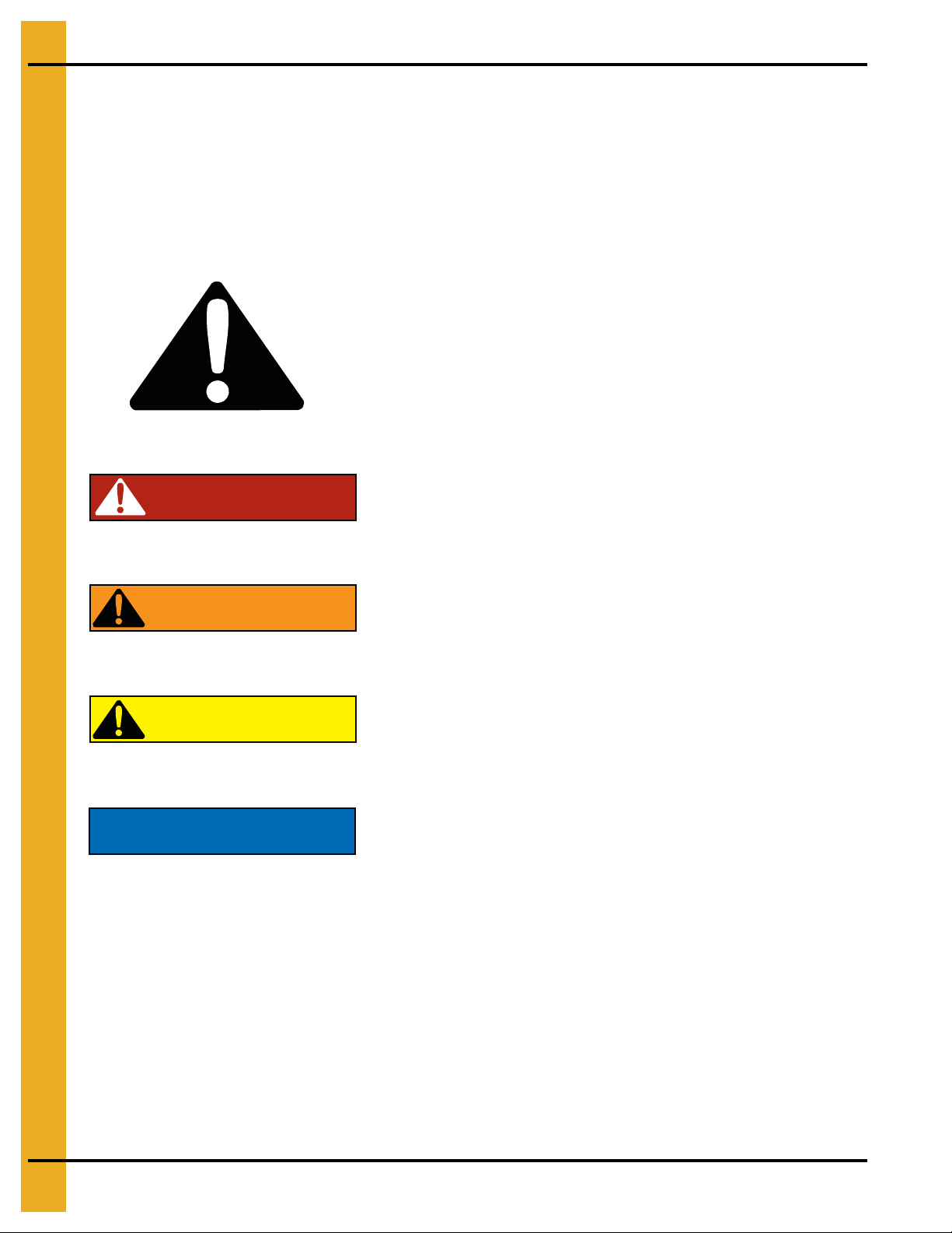
This is the safety alert symbol. It is used to alert you
to potential personal injury hazards. Obey all safety
messages that follow this symbol to avoid possible
injury or death.
WARNING indicates a hazardous situation which, if not
avoided, could result in death or serious injury.
CAUTION, used with the safety alert symbol, indicates a
hazardous situation which, if not avoided, could result in
minor or moderate injury.
NOTICE is used to address practices not related to
personal injury.
DANGER indicates a hazardous situation which, if not
avoided, will result in death or serious injury.
Safety Guidelines
This manual contains information that is important for you, the owner/operator, to know and understand.
This information relates to protecting personal safety and preventing equipment problems. It is the
responsibility of the owner/operator to inform anyone operating or working in the area of this equipment
of these safety guidelines. To help you recognize this information, we use the symbols that are defined
below. Please read the manual and pay attention to these sections. Failure to read this manual and its
safety instructions is a misuse of the equipment and may lead to serious injury or death.
DANGER
WARNING
CAUTION
NOTICE
4 PNEG-010 Vane Axial Fan
Page 5
1. Safety
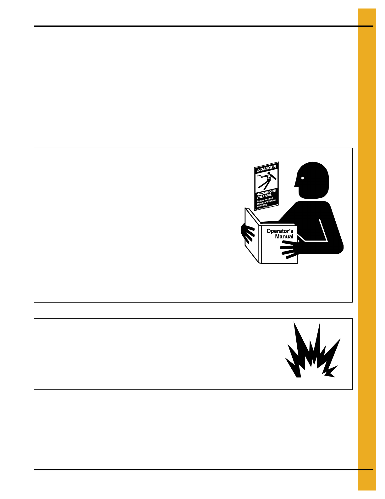
Follow Safety Instructions
Carefully read all safety messages in this manual and
safety signs on your machine. Keep signs in good
condition. Replace missing or damaged safety signs. Be
sure new equipment components and repair parts include
the current safety signs. Replacement safety signs are
available from the manufacturer.
Learn how to operate the machine and how to use controls
properly. Do not let anyone operate without instruction.
Keep your machinery in proper working condition.
Unauthorized modifications to the machine may impair
the function and/or safety and affect machine life.
If you do not understand any part of this manual or need
assistance, contact your dealer.
Read and Understand Manual
Install and Operate Gas-Fired Equipment Properly
Fuel supply should be installed by a qualified gas
technician and must meet local and state codes for
gaseous fuel supplies.
Disconnect and lock out all fuel sources before
servicing equipment.
Explosive Gases
Safety Instructions
Our foremost concern is your safety and the safety of others associated with this equipment. We want to
keep you as a customer. This manual is to help you understand safe operating procedures and some
problems that may be encountered by the operator and other personnel.
As owner and/or operator, it is your responsibility to know what requirements, hazards, and precautions
exist, and to inform all personnel associated with the equipment or in the area. Safety precautions may be
required from the personnel. Avoid any alterations to the equipment. Such alterations may produce a very
dangerous situation where SERIOUS INJURY or DEATH may occur.
This equipment shall be installed in accordance with the current installation codes and applicable
regulations, which should be carefully followed in all cases. Authorities having jurisdiction should be
consulted before installations are made.
PNEG-010 Vane Axial Fan 5
Page 6
1. Safety
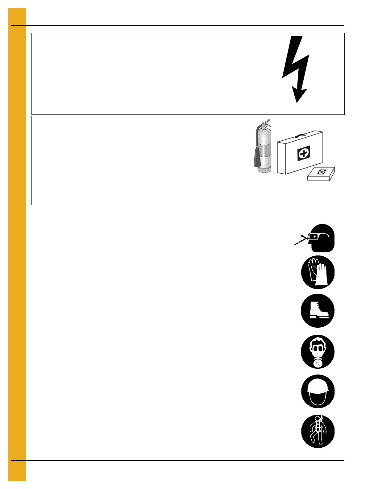
Install and Operate Electrical Equipment Properly
Electrical controls should be installed by a qualified electrician
and must meet the standards set by the National Electrical Code
and all local and state codes.
Disconnect and lock out all power sources before installing
wires/cables or servicing equipment.
Electric Shock Hazard
Prepare for Emergencies
Be prepared if fire starts.
Keep a first aid kit and fire extinguisher handy.
Keep emergency numbers for doctors, ambulance service,
hospital, and fire department near your telephone.
Keep Emergency Equipment
Quickly Accessible
Wear Protective Clothing
Wear close-fitting clothing and safety equipment appropriate
to the job.
Remove all jewelry.
Tie long hair up and back.
Wear safety glasses at all times to protect eyes from debris.
Wear gloves to protect your hands from sharp edges on plastic
or steel parts.
Wear steel-toed boots to help protect your feet from falling
debris. Tuck in any loose or dangling shoestrings.
A respirator may be needed to prevent breathing potentially
toxic fumes and dust.
Wear a hard hat to help protect your head.
Wear appropriate fall protection equipment when working at
elevations greater than six feet (6').
Eye Protection
Gloves
Steel-Toed Boots
Respirator
Hard Hat
Fall Protection
6 PNEG-010 Vane Axial Fan
Page 7
2. Decals
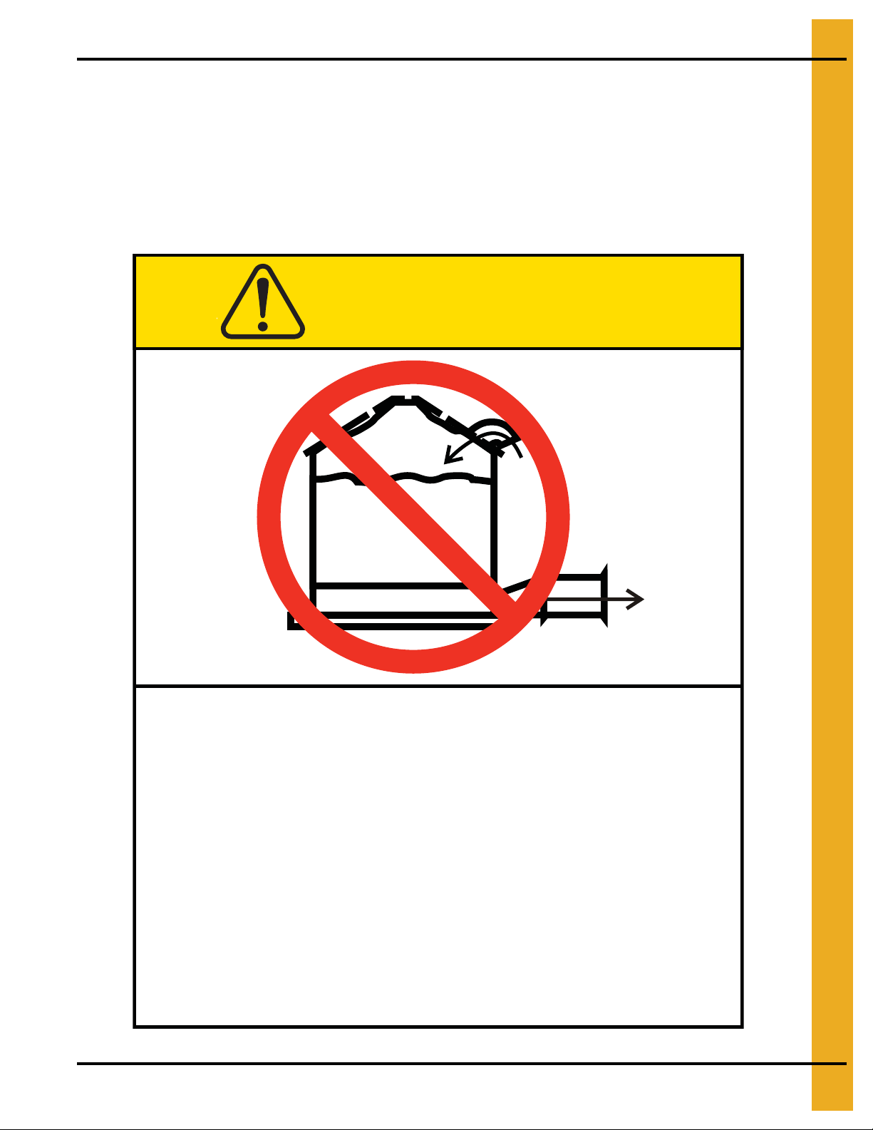
Excessive vacuum (or pressure) may
damage roof. Use positive aeration
system. Make sure all roof vents are
open and unobstructed. Start roof
fans when supply fans are started.
Do not operate when conditions exist
that may cause roof vent icing.
DC-969
CAUTION
GSI Group, Inc. 217-226-4421
Roof Damage Warning and Disclaimer
The manufacturer does not warrant any roof damage caused by excessive vacuum or internal
pressure from fans or other air moving systems. Adequate ventilation and/or “makeup air” devices
should be provided for all powered air handling systems. The manufacturer does n ot recommend
the use of downward flow systems (suction). Severe roof damage can result fro m any blockage of
air passages. Running fans during high humidity/cold weather conditions can cause air exhaust
or intake ports to freeze.
PNEG-010 Vane Axial Fan 7
Page 8
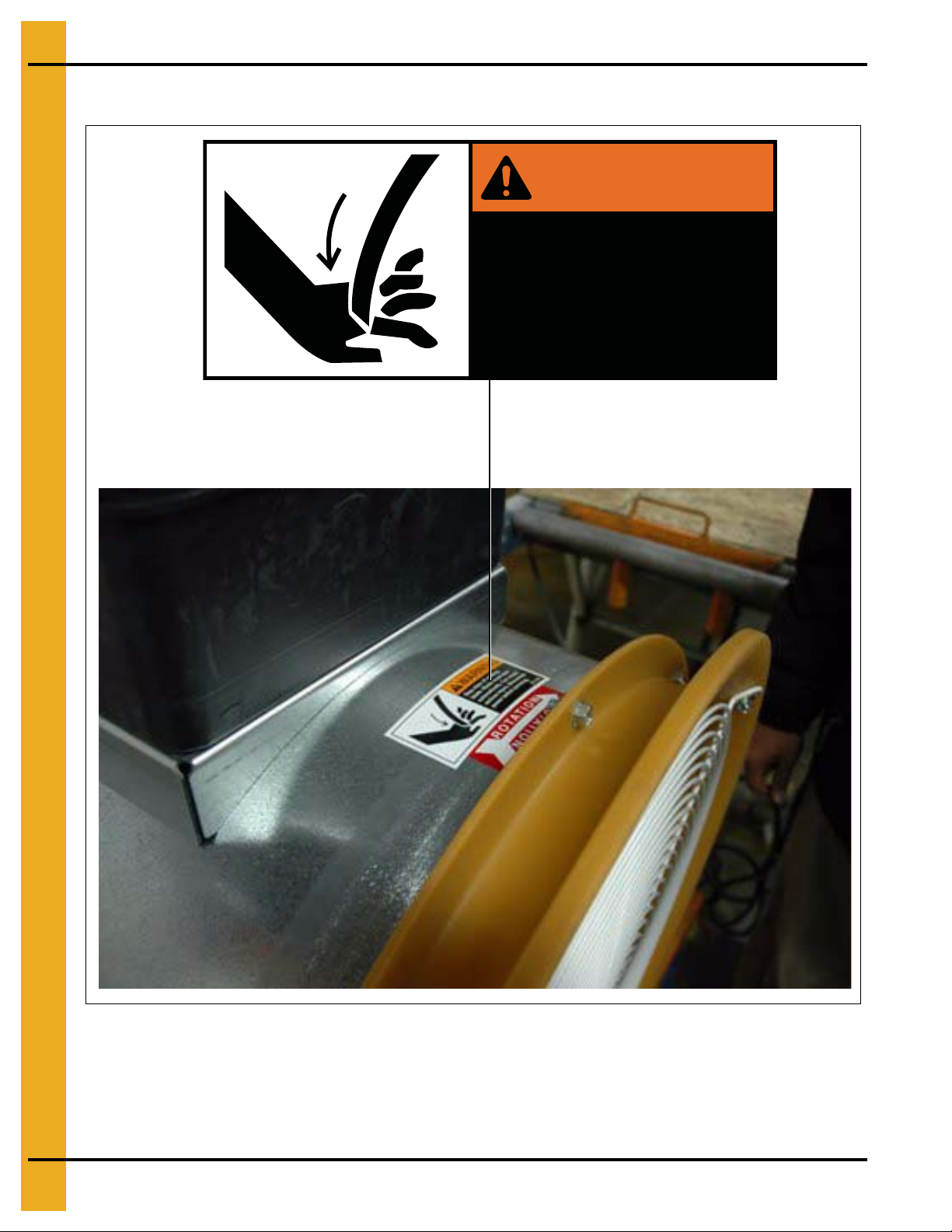
2. Decals
Stay clear of rotating
blade. Blade could start
automatically. Can cause
serious injury. Disconnect
power before servicing.
DC-1225
WARNING
Safety Alert Decals
8 PNEG-010 Vane Axial Fan
Page 9
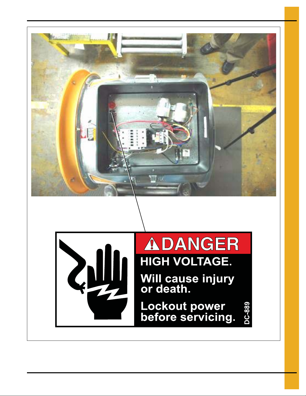
2. Decals
PNEG-010 Vane Axial Fan 9
Page 10
3. Installation Instructions
TR-4734
A = 20" for fans without heaters
A = 44'' for fans with heaters
TR-6918 and TR-6919
A = 32" for fans without heaters
A = 56" for fans with heaters
TR-7048
A = 45" for fans without heaters
A = 69" for fans with heaters
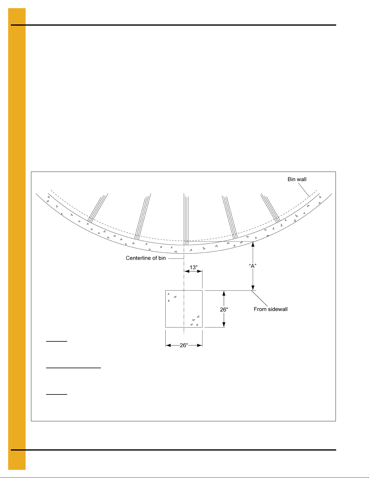
Vane Axial Fan Pad
Placement of the Fan Pad: Transitions/Fans/Heaters Only
If a fan or fan and heater is to be installed, refer to Figure 3A to determine the concrete pad size.
1. The top of this pad should be level with the top of the bin’s foundation.
2. Recommended pad thickness is 4" minimum.
3. Front of pad should be perpendicular to bin wall.
4. Pad for heater not required, but if it is to added, pour the pad to cover both locations.
For fans and transitions used in aeration duct system applications, refer the transition and aeration
installation instructions.
IMPORTANT: Fan pad and fan must be level and smooth for proper operation. Vibration problems can
result from improper fan leveling.
10 PNEG-010 Vane Axial Fan
Figure 3A
Page 11

4. Fan Installation
Pre-Installation Requirements
Foundation
Use the dimension Figure 5A on Page 15 in the specifications section of this manual to determine the
physical size of the fan to be installed. Use the dimensions shown to determine the position of the fan
installation with respect to other equipment.
For proper operation of the fan, the unit is to be mounted on a level pad. The fan should not be
anchored to the pad, but it should be allowed to “float” on the pad. Refer to Figure 5A on Page 15 for fan
pad location in the specifications section of this manual for recommendations of pad plac ement with
respect to various catalog transition ducts.
Transition
The transition duct should be all metal construction, with a gradual angle to the rectangular opening in the
bin wall. The duct should allow for a smooth transition with minimal resistance of the airflow from the fan
discharge to the bin plenum. Keep the entrance of the plenum as clear as possible from obstructions by
floor support.
Roof Exhaust
Adequate exhaust air openings in the roof are required to prevent any additional back pressure from
building in the bin. See roof damage warning and disclaimer on Page 7.
Power Supply
Adequate power must be supplied to the fan for reliable operation. Consult the local power company and
have a representative survey the installation. Only the power company can ensure that their system is
sized properly to provide adequate service to the installation and new equipment.
Wire Size
Undersized wire can lead to voltage drop which causes motor overheating and shortened motor life.
Use the electrical specifications chart on Page 16 in this manual to size the supply wire according to
the horsepower of the fan and the distance to the power supply. Refer to fan specifications section
on Page 15 of this manual to find the full load current of the motor for a given fan size. The full load curre nt
can also be found on the motor nameplate.
Service Disconnect
Each fan motor must be supplied with an independent power circuit, equipped with a fused disconnect
switch. Locate this switch near the unit, as the power should be shut off before servicing the fan.
It is the customer’s responsibility to provide a fused disconnect and motor overload protection. These must
be properly sized and connected to allow proper motor operation. Failure to provide these components
could cause severe motor damage and void the manufacturer’s warranty.
PNEG-010 Vane Axial Fan 11
Page 12
4. Fan Installation
Always disconnect and lock out power before working on or around fan.
Fan Installation
1. Remove packaging materials and inspect fan for any shipping damages. Report these at once to
the shipper.
2. Check all fasteners on the fan to make sure they are tight (fasteners may loosen during shipment).
Tighten any loose fasteners, check for proper clearance and re-tighten.
3. Check all electrical connections that may have loosened during shipment.
4. Rotate the fan blade. Blade should rotate freely and should not make contact with the housing
sides or venturi.
5. Place fan in proper location on the fan pad. Attach fan to transition duct and seal connection
with caulk.
6. Check all joints and seams around the lower part of the bin. Verify that these are well sealed to
prevent air leakage from the bin plenum. Inspect the transition duct as well. Seal any leaks that may
be present to prevent air losses that reduce fan efficiency.
7. Level fan. Fan pad should be poured flat and level, however, it may be necessary to shim the legs
provided on the fan housing to level the fan. Fans not resting on support legs may have excess
vibration which can lead to premature wear and tear on fan components.
DANGER
IMPORTANT: Electrical installation must be performed by a qualified electrician, in accordance with
National and Local Electrical Codes. Any violation of electrical wiring codes could
jeopardize the warranty.
Electrical Installation
1. Verify that the incoming power supply has been deemed adequate by the local power company.
2. Verify that the wiring supplying power to the fan is sized correctly for the distance away from supply
and fan horsepower. (See tables in specification section on Page 16 of this manual.)
3. Verify that the safety disconnect is installed and sized correctly for the fan size. (See tables in
specification section on Page 16 of this manual.)
4. Install a machine to earth ground for each individual fan. Refer to ground rod installation on Pa ge 14
in this manual.
5. The following wires must be supplied to each fan. Units without control transformers require a
separate neutral and earth ground connection.
1 PH 230V L1, L2, N, G
3 PH 230V L1, L2, L3, N, G
3 PH 230V with optional transformer kit L1, L2, L3, G
3 PH 460V/575V L1, L2, L3, G
6. The starter controls require 115 VAC power to operate. On 230 volt 3 phase units, this power is
supplied by L1 to neutral.
12 PNEG-010 Vane Axial Fan
Page 13

4. Fan Installation
CAUTION
The voltage between L1 and N must be 115 VAC. Any other voltage will cause
damage to equipment.
Use a #6 or approved size bare copper ground wire. Install a 5/8" diameter 8' long
copper-clad ground rod, 2' away from the foundation and 1' below the surface of the
ground or in accordance with local requirement s.
Check this voltage before starting unit. If voltage is not within 105 VAC-125 VAC, check for proper
voltage on L2 or L3 and move to appropriate leg. If voltage is not acceptable, install a 1/4 KVA
step-down transformer. (NOTE: Grounded B and some open delta power supplies will require this
transformer kit.)
Final Check
Check to make sure all safety guards are in place and not damaged. Replace damaged parts. Check to
make sure all decals are visible and not damaged. Replace damaged decals. Check to make sure all
control boxes are closed and no wiring is exposed.
Test Run
When the fan is completely installed, the unit will need to be checked for proper rotation. Provide
power to the fan controls and start the fan momentarily. Make sure that the fan blade rotation is in the
direction that the decal on the fan housing illustrates. If the blade is rotating the wrong direction, have the
electrician correct the wiring.
Figure 4A
PNEG-010 Vane Axial Fan 13
Page 14

4. Fan Installation
Dig a hole large enough to hold 1 or 2
gallons of water. Work the ground rod
into the earth until it is completely in
the ground.
Machine to Earth Ground
It is very important that a machine to earth ground rod be installed at the fan. This is true even if there is
a ground at the pole 15' away. This ground needs to be as close to the fan as possible , but no more than
8' away. The ground rod should be connected to the fan control panel with at least a #6 solid bare copper
ground wire or in accordance with local requirements. The machine to earth ground provides additional
safety if there is a short. It also provides the grounding necessary for long life and operation of the solid
state circuit boards used on control circuits and the electronic ignition systems.
Previously Installed Units
It is recommended that previously installed units be checked to see that a machine to earth ground has
been installed by an electrician.
Proper Installation of the Ground Rod
Ground rods and wires are not supplied. It is recommended that the rod not be driven into dry ground. Th e
following steps ensure proper ground rod installation:
1. Dig a hole large enough to hold 1 to 2 gallons of water.
2. Fill hole with water.
3. Insert rod through water and jab it into the ground.
4. Continue jabbing the rod up and down, the water will work its way down the hole, making it possible
to work the rod completely into the ground. This method of installing the rod gives a good conductive
bond with the surrounding soil.
5. Connect the bare copper ground wire to the rod with the proper ground rod clamp.
6. Connect the bare ground wire to the fan control boxes with a grounding lug.
7. Ground wire must not have any breaks or splices. Insulated wire is not recommended for grounding.
Figure 4B
14 PNEG-010 Vane Axial Fan
Page 15

5. Fan Specifications
Fan
A (Bolt circle) 13-1/2" 13" 15-1/4" 19-1/4" 25-3/4" 27-3/4" 30"
B (Inside diameter) 12-1/4" 11-7/8" 14-1/4" 18-1/4" 24-1/4" 26-5/16" 28-1/4"
C (CL to bottom of leg) 7-9/16" 7-9/16" 10-7/8" 11-7/8" 15-7/16" 16-7/8" 18-1/8"
D (Length) 16-1/8" 16-1/8" 16-3/16" 17/20" 24" 24" 24"
E - - - - 26-3/4" - 26-3/4"
12'' Diameter
1 HP
12'' Diameter
0.75 HP
14'' Diameter
18'' Diameter
1.5 HP/3 HP
24'' Diameter 26'' Diameter 28'' Diameter
NOTE: All dimensions in inches.
Figure 5A Fan Dimensions
PNEG-010 Vane Axial Fan 15
Page 16

5. Fan Specifications
Fan Horsepower 3/4 1
RPM 3450 3450
Phase 1 3 1 3
Volts 230 230 460 575 230 230 460 575
Full Load Amps 5.5 2.6 1.3 1 5.5 3 1.5 1.2
Minimum Wire Size Copper Wire Copper Wire
50' Run 1414141414141414
100' Run 14 14 14 14 14 14 14 14
200' Run 1214141412141414
300' Run 10 14 14 14 10 14 14 14
Minimum Wire Size Aluminum Wire Aluminum Wire
50' Run 14 14 14 14 14 14 14 14
100' Run 1414141414141414
Fan Electrical Specifications
200' Run 10 14 14 14 10 14 14 14
300' Run 8 12 14 14 8 12 14 14
Fuse Size (Slow Blow) 15 10 5 5 15 10 5 5
Breaker Size 20 15 10 10 20 15 10 10
Fan Horsepower 1-1/2 3
RPM 3450 3450
Phase 1 3 1 3
Volts 230 230 460 575 230 230 460 575
Full Load Amps 7.5 4.6 2.3 1.8 15 7.4 3.7 3
Minimum Wire Size Coppe r Wire Copper Wire
50' Run 1414141412121414
100' Run 12 14 14 14 10 12 12 12
200' Run 8 12 14 14 8 10 12 12
300' Run 6 10 12 12 6 8 10 10
Minimum Wire Size Aluminum Wire Aluminum Wire
50' Run 12 12 14 14 12 12 12 12
100' Run 10 12 12 14 8 10 12 12
200' Run 6 10 12 12 6 10 10 10
300' Run 4 10 12 12 4 8 10 10
Fuse Size (Slow Blow) 15 10 5 5 30 15 10 10
Breaker Size 20 15 10 10 40 20 1 5 15
16 PNEG-010 Vane Axial Fan
Page 17

5. Fan Specifications
Fan Horsepower 5 7
RPM 3450 3450
Phase 1 3 1 3
Volts 230 230 460 575 230 230 460 575
Full Load Amps 30 18 9 6.9 30 18 9 6.9
Minimum Wire Size Copper Wire Copper Wire
50' Run 101012121010 12 12
100' Run 8 10 12 12 8 10 12 12
200' Run 4 8 10 12 4 8 10 12
300' Run 4 6 8 10 4 6 8 10
Minimum Wire Size Aluminum Wire Aluminum Wire
50' Run 8 8 12 12 8 8 12 12
100' Run 6 8 10 12 6 8 10 12
200' Run 3 6 10 10 3 6 10 10
300' Run 2 4 8 10 2 4 8 10
Fuse Size (Slow Blow) 40 25 15 15 40 25 15 15
Breaker Size 60 30 15 15 60 30 15 15
Fan Horsepower 10 15
RPM 3450 3450
Phase 1 3 1 3
Volts 230 230 460 575 230 230 460 575
Full Load Amps 47 25 13 9.6 57 32 16 14
Minimum Wire Size Copper Wire Copper Wire
50' Run 8 8 12 12 6 6 10 10
100' Run 6 6 10 12 4 4 10 10
200' Run 4 4 10 10 2 2 10 10
300' Run 2 2 8 8 0 0 8 10
Minimum Wire Size Aluminum Wire Aluminum Wire
50' Run 6 6 12 12 4 4 8 8
100' Run 4 4 10 10 2 2 8 8
200' Run 2 2 8 10 0 0 6 8
300' Run 0 0 6 8 0 0 4 6
Fuse Size (Slow Blow) 60 30 20 15 75 40 20 20
Breaker Size 80 40 20 20 100 60 30 20
PNEG-010 Vane Axial Fan 17
Page 18

6. Fan Operation
WARNING
Make certain all guards and covers are securely in place.
After initial installation and also prior to using the unit each season, check the operation to ensure pro per
functioning, adjustment and reliability.
Fan Start-Up
1. Make certain the unit is properly installed and connected, as described within the installation section
of this manual. All air passage joints and seams must be well sealed.
2. With main power supply turned OFF, rotate the blade by hand to make certain it turns freely without
contacting the housing or venturi.
3. Open roof doors to allow airflow at all times when fan is operating.
IMPORTANT: Refer to roof damage disclaimer in the safety section on Page 7 of this manual.
4. Turn ON main power disconnect switch.
5. Press the fan Start button and check the following:
a. Check direction of blade rotation. Correct if needed by following the instructions on the motor.
b. Check to make sure the blade comes to full operating speed in less than 10 seconds. If there is
any doubt as to proper operation, check the current draw of the motor. The motor amperage
should not exceed the maximum full load amps listed on the motor nameplate.
Fan Shut Down
1. Press the fan Stop button on units equipped with motor controls.
2. Shut off electrical power at main and at disconnect.
3. Close the roof openings and cover fan inlet to prevent harmful back-draft air currents from passing
through the grain and to avoid grain infestation from rodents and insects.
Maintaining Grain Quality
To properly maintain the quality of stored grain, it is necessary to keep the grain dry, cool and insect free.
Any one of these problems can contribute to spoilage. Wet, warm grain promotes insect growth as well as
grain spoilage. Cool, dry grain can keep for long periods of time. (See Chart on Page 19.)
It is recommended that the grain be kept cool (avoid free zing as freezing can reduce quality). Grain should
be cooled through the fall and winter, warmed in the spring and summer.
18 PNEG-010 Vane Axial Fan
Page 19

6. Fan Operation
Safe moisture for normal winter storage of shelled corn is about 15%. Grain to be stored through the
summer or long term, needs to be 1 to 3 points dryer.
Grain Storage
IMPORTANT: Conditions and requirements may vary from area to area. Contact the local agriculture
extension office or state agriculture university for more exact guidelines.
Average grain temperature should be above 35°F in the winter and below 65°F in the summer. Always try
to keep the grain within 10°F-15°F of the average monthly outside temperature. This means grain may
need to be aerated on warm days during the winter to stay above 35°F when freezing temperatures are
predominate. During the summer it may be necessary to aerate the grain on cool nights, so the 65°F
temperature is not exceeded during the hot days of summer.
If the grain is to be stored more than 1 year, it has to be recooled the following fall and winter, repeating
the process as long as the grain is in storage. Frequent and regular inspection (at least weekly during
fall and spring) is the best prevention against grain spoilage.
Equilibrium Moisture Chart
Air
Temperature
20°F
30°F
40°F
50°F
60°F
70°F
80°F
35 40 45 50 55 60 65 70 75 80 85 90 95 100
11.2 11.7 12.7 13.7 14.5 15.1 16.2 17.1 18.0 19.6 21.2 23.5 25.8 29.1
10.8 11.3 12.2 13.1 13.9 14.6 15.5 16.4 17.4 18.7 20.2 22.5 25.0 28.3
10.5 11.0 11.7 12.5 13.3 14.0 14.8 15.5 16.6 17.8 19.4 21.5 24.2 27.5
10.1 10.6 11.3 12.0 12.7 13.3 14.1 14.8 15.8 16.9 18.6 20.5 23.4 26.7
9.7 10.2 10.9 11.6 12.1 12.7 13.4 14.2 15.0 16.0 17.8 19.5 22.6 25.9
9.0 9.7 10.4 11.1 11.5 12.0 12.8 13.5 14.5 15.4 16.8 18.5 21.3 24.5
8.3 9.1 9.8 10.5 10.8 11.2 12.1 13.0 13.9 14.8 15.8 17.4 20.0 22.8
Percentage Relative Humidity
Approximate Allowable Holding Time for Field-Shelled Corn, to Maintain Grade*
Grain
T emperature
15%
Days
18%
Days
20%
Days
22%
Days
24%
Days
26%
Days
28%
Days
30%
Days
40°F 898 195 85 54 38 28 24 20
50°F 451 102 46 28 19 16 13 11
60°F 242 63 26 16 10 8 6.5 5.5
70°F 147 37 13 8 5 4 3.5 3
80°F 109 27 10 6 4 3 2.5 2
*Allowable holding time for field-shelled corn at various grain temperatures and moisture.
PNEG-010 Vane Axial Fan 19
Page 20

6. Fan Operation
DANGER
Always disconnect and lock out power before working on or around fan.
CAUTION
Although the taper-lock method of retaining the blade onto the motor shaft is
very simple and obvious, it is essential that the following points be read
carefully and fully understood, as improper installation can result in serious or
fatal injury caused by a loose, fast flying blade.
THREADED BUSHING HOLES: The threaded holes within the bushing are
provided for disassembly purposes only. Do not attempt to use these holes for
re-assembly, as they will not allow the parts to become locked onto the shaft,
thereby causing an extremely hazardous operating condition.
CLEARANCE HOLES: When reassembling parts, the cap screws must be
installed through the UNTAPPED.
NR
Approximate Hours of Fan Time to Change Bin Temperature
Fan Size
HP
1 73 79 90
1.5 56 61 65 66 76 82 92
3 44 51 52 57 63 69 78 93
7 38 42 44 47 52 56 61 71 81 79 93
10 35 37 41 42 45 49 53 62 71 72 82 92
15 30 32 35 39 40 42 45 54 63 62 70 80
Approximate BU 4500 6500 8500 11000 13500 16500 19500 27000 35500 28000 38500 50500
1. Bushels are rounded and approximate.
2. The hours required are based on clean grain. High moisture grain and grain containing fines or foreign material will
require more time to complete the air change.
3. Not Recommended: Bins in the NR range, may require fan(s) of a different size to get the cool time into the
accepted range.
4. Bins requiring more than 100 hours of aeration to totally change the temperature may require continuous aeration at
about 1/10
Bin Diameter Approximate 22' to Eave-Approximate Hou rs
of Fan Time Required
18 21 24 27 30 33 36 42 48 36 42 48
NR NR NR NR NR NR NR NR NR
NR NR NR NR NR
th
CFM per bushel or some other acceptable method.
Approximate 32' to Eave
NR NR NR NR
NR
Fan Blade Removal and Installation
The fan blade is secured to the motor shaft by the use of a taper-lock bushing, motor shaft key and
cap screws. The size, quantity and torque of cap screws required will depend on the model of the fan.
20 PNEG-010 Vane Axial Fan
Page 21

6. Fan Operation
Removal
1. LOCK OUT THE MAIN POWER SUPPLY and remove the fan guard and venturi.
2. Remove the three (3) cap screws from the clearance holes in taper-lock bushing. Inspect for thread
damage and set aside for later re-installation (do not use these bolts for Step 3, bushing removal).
3. Install two (2) grade 5 (or better) cap screws into the THREADED HOLES in the bushing and turn
them in by hand until they bottom against the front surface of the blade. These cap screws should
not be used for re-assembly, as some thread distortion could occur during the removal operation.
Grade 5 screws are marked with three (3) 120° spokes on the head and are more du rable than low
strength unmarked bolts.
NOTE: Do not attempt to use low strength (unmarked) bolts to remove the bushing, as the bolts may
break off.
4. Block blade to prevent it from turning and GRADUALLY TURN IN THE CAP SCREWS (up to
1/4 turn at time), until the blade breaks loose from the bushing and motor shaft. Carefully remove
bushing and blade. (With the blade free from the bushing, a blade puller can be used to pull the
bushing off of motor shaft, if required). Re-attach bushing onto blade to prevent the loss of parts and
also to maintain the original alignment of bushing to blade.
Inspect blade and bushing at this time, looking for any cracks, thread or bolt damage, warpage, etc.
Consult your dealer or the factory for any questions concerning damage.
Installation
1. Carefully clean motor shaft, key, bushing and bore of blade. MAKE SURE MAIN POWER IS
LOCKED OUT and that shaft and key are completely free of rust and burrs. DO NOT lubricate the
bushing or cap screws. CHECK AND MAKE SURE ALL MOTOR MOUNT BOLTS ARE PROPERLY
TIGHTENED. Before installing the blade, check the following:
a. All foreign material should be removed from the blade.
b. Carefully inspect the blade weldment and hub casting for damage, cracks or other defects.
Contact the factory if there is any question regarding the structural integrity of the blade.
2. Slide blade over motor shaft and locate it as far onto the motor shaft as possible.
3. Align the keyway in the bushing with the key and SLIDE bushing onto motor shaft. Do not attempt to
drive the bushing onto the shaft, as it may damage the motor bearings.
4. Rotate the bushing and blade so their key slots are in line and loosely attach the blade to the bushing.
MAKE SURE THE CAP SCREWS ARE INSERTED INTO THE UNTHREADED CLEARANCE
HOLES IN THE BUSHING. Refer to previous CAUTION note on Page 20. Locate the bushing so it
is approximately flush with the end of motor shaft. Make certain that the proper cap screws are used
for re-assembly and no damage has occurred to these screws during disassembly. Use only the
special type bolts supplied with the original blade.
5. Use an INCH-POUNDS torque wrench and GRADUALLY TIGHTEN the three (3) cap screws
(1/4 turn at a time) until the taper bushing becomes fully seated. Refer to the following chart
on Page 22 for recommended cap screw tightening torques. DO NOT EXCESSIVELY
OVERTIGHTEN THE BUSHING.
6. Turn blade by hand and check it for freedom of rotation and uniform clearance around venturi before
re-installing the fan guard.
PNEG-010 Vane Axial Fan 21
Page 22

7. Fan Service
Do not attempt to pull the flange of the bushing flush with the blade hub.
A clearance of 1/8'' to 1/4'' must be maintained between bushing flange and
blade hub surface. Blade will loosen and cause damage or injury.
Fan Blade Inspection and Maintenance
Pre-season inspections should be done on the fan blade to look for the following:
1. Any debris (stalks, bees wings, mud, insects and insect nests) accumulated on the surfaces of the
fan blade. Remove these items as they will likely disrupt airflow over the fan airfoils and can
potentially cause vibration problems.
2. Inspect the fan blade for any broken, cracked or loose parts. Blade should NOT be operated with
broken or loose parts. Contact dealer for determination of the repairs required.
WARNING
Browning Taper-Lock
Bushing Bolt Tightening Torque
Bushing Size Hex Bolt Size To rque (in ch . lbs.)
H 1/4"-20 x 3/4" 95
P 5/16"-18 x 1" 192
Fan Motor
Removal and Installation
In the event of motor failure, remove the motor, as described and take it to the nearest Authorized Service
Station. AUTHORIZED SERVICE STATIONS ARE THE ONLY PLACES THAT CAN PROVIDE MOTOR
WARRANTY. Motor service and repair at other places will be at owner’s expense. If service station
determines motor failure to be caused by faulty material or workmanship, repair will be under warranty
when within the warranty period. Motor failure because of external causes will result in a charge to the
owner for repair.
1. LOCK OUT THE MAIN POWER SUPPLY, then remove fan guard, venturi and blade as
outlined earlier.
2. Open motor junction box cover and disconnect the motor lead wires from within the box.
NOTE: Tag or otherwise identify wires for ease of re-assembly.
3. Remove motor mount bolts. If there are any shims between the motor and its base, note their
locations so they can be properly installed during re-assembly.
4. Disconnect the motor end of the motor conduit, if required, then carefully pull conduit and wires
through hole in the motor junction box. Remove motor. If motor requires service, take it to an
Authorized Service Station.
5. To re-install motor, slide onto motor base plate and replace shims (if required) between motor and
base plate. Re-install motor mount bolts and washers and fully tighten them at this time. Re-install
conduit and wires and carefully remake all electrical wiring connections.
NOTE: Make sure to install and tighten the blade in accordance with earlier instructions.
22 PNEG-010 Vane Axial Fan
Page 23

7. Fan Service
DANGER
Do not touch electrical connections before you first ensure that power has
been disconnected. Electrical shock can cause serious or fatal injury. Only
qualified personnel should attempt the installation, operation and maintenance
of this equipment.
CAUTION
To avoid damage to motor bearings, grease must be free of dirt.
General Inspection
Inspect the motor at regular intervals, approximately every 500 hours of operation or every three (3)
months, whichever occurs first. Keep the motor clean and the ventilation openings clear. The following
steps should be performed at each inspection:
1. Check that the motor is clean. Check that the interior and exterior of the motor is free of dirt, oil,
grease, water, etc. Oily vapor, paper pulp, textile lint, etc., can accumulate and block motor
ventilation. If the motor is not properly ventilated, over heating can occur and cause early
motor failure.
2. Check all electrical connectors to be sure that they are tight.
Lubrication and Bearings
Bearing grease will lose its lubricating ability over time, not suddenly. The lubricating ability of a grease
(over time) depends primarily on the type of grease, the size of the bearing, the speed at which the bearing
operates and the severity of the operating conditions. Good results can be obtained if the following
recommendations are used in the maintenance program. Type of grease: A high grade ball or roller
bearing grease should be used.
Recommended grease for standard service conditions:
1. Polyrex EM (Exxon Mobil)
Equivalent and compatible greases include:
1. Texaco polystar
2. Rykon premium #2
3. Pennzoil pen 2 lube
4. Chevron SRI
Lubrication Procedure
Be sure that the grease you are adding to the motor is compatible with the grease already in the motor.
With Grease Outlet Plug
1. Clean all grease fittings.
2. Remove grease outlet plug.
3. Add the recommended amount of grease.
4. Re-install grease outlet plug.
PNEG-010 Vane Axial Fan 23
Page 24

7. Fan Service
Without Grease Outlet Plug
This requires disassembly of the motor. Contact local motor shop for assistance.
Volume of Grease to Relubricate
Bearings (Teaspoons)
NEMA Frame Size
Up to 210 incl. 2
Over 210 to 280 incl. 3.9
Over 280 to 360 incl. 5.2
Over 360 to 449 incl. 13.4
Lubrication Intervals - Ball Bearing Motors
1800 RPM - NEMA Frame Size 3600 RPM - NEMA Frame Size
Type of Annual Usage
Up to 280
incl.
Over 280 to
360 incl.
Over 360
Up to 280
incl.
Over 280 to
360 incl.
Over 360
Continuous Normal Duty * 9500 Hrs 7400 Hrs 3500 Hrs 3600 Hrs 2200 Hrs 2200 Hrs
Continuous Severe Duty ** 4750 Hrs 3700 Hrs 1750 Hrs 1800 Hrs 1100 Hrs 1100 Hrs
Seasonal Service Motor
(idle 6 months)
* Clean, little corrosion with 40°C maximum temperature.
** Moderate dirt, corrosion with 50°C maximum temperature.
Average hours per month = 730.
Lubrication at beginning of season and then follow the appropriate duty interval above.
24 PNEG-010 Vane Axial Fan
Page 25

8. User Servicing Instructions and Troubleshooting
Important Information Regarding Fuse Replacement
This product employs overload protection (fuse). A blown fuse indicates an overload or short circuit
situation. If the fuse blows, disconnect all power to the product. Replace the fuse as per the user servicing
instructions (follow product marking for proper fuse rating) and check the product. If the replacement fuse
blows, a short circuit may be present and the user should discontinue use of the product until customer
service can be contacted for further assistance.
Fan Troubleshooting Chart
Symptom Possible Cause Solution
1. To replace blown fuse, grasp center
1. Blown fuse or breaker in
disconnect switch.
of fuse securely and pull carefully
outward to remove fuse from fuse holder.
RISK OF FIRE
equally rated fuse shown on panel label.
. Replace fuse only with
1. Fan does not run.
2. Fan runs for a short period of
time then shuts off.
3. Fan makes ticking noise.
2. Main power not turned ON.
3. Defective wiring or loose connection.
4. Incorrect wire size.
5. Overload kicked out. 5. Check manual reset, push in to reset.
6. Defective motor. 6. Replace motor.
7. Defective magnetic contactor. 7. Check the magnetic contactor.
1. Undersize wiring.
2. Low line voltage at the installation
power failure.
3. Magnetic contactor malfunctioning. 3. Change magnetic contactor.
4. Defective start/stop button. 4. Replace necessary part.
5. Overload setting incorrect. 5. Adjust overload to proper setting.
1. Fan blade hitting housing.
2. Turn power ON at all disconnects ahead of
the unit.
3. Follow wiring diagram and tighten any
loose connections.
4. See wire size charts on Page 16 for proper
wire size and change if needed.
1. Check to see that power supply wires
are the proper size, contact the local
power company.
2. Call power company after making sure wire
size is correct.
1. Stop fan and turn OFF power. Remove fan
guard and check to see if fan blade is hitting
the housing. Adjust motor or fan blade
position to obtain proper clearance.
2. Motor bearing bad. 2. Replace motor bearing.
1. Fan not level. 1. Level fan.
4. Fan vibrates.
2. Fan has dirt deposit on blade. 2. Clean blade.
3. Motor shaft is bent. 3. Replace motor.
4. Blade not mounted properly on shaft. 4. Moun t blade properly on shaft.
5. Blade out of balance. 5. Replace or have blade rebalanced.
PNEG-010 Vane Axial Fan 25
Page 26

8. User Servicing Instructions and Troubleshooting
Fan Troubleshooting Flow Chart
26 PNEG-010 Vane Axial Fan
Page 27

12''-14'' Fan Parts
9. Parts List
Ref #
12" 0.75 HP 12'' 1 HP 14'' 1 HP
1 F-7359 F-7225 F-7230 VA Housing Assembly
2 - MTR-0145 MTR-0145 Motor 1 HP 1 PH 3400 RPM
2 FH-5579 - - Motor 1 HP 1 PH 3500 RPM
3 F-7124 F-7252 F-7301 GRP - VA Blade
4 F-7233 F-7233 F-7233 GRP - Safety Washer
5 F-7177 F-7177 F-7178 Grill Guard
6 S-3611 S-6606 S-6606 Flange Bolt 5/16"-18 x 3/4" ZN Grade 5
7 S-845 S-3611 S-3611 Flange Nut 5/16"-18 ZN YDP
8 S-6606 S-845 S-845 Flat Washer 5/16" USS SAE YDP Grade 2
Part #
Description
PNEG-010 Vane Axial Fan 27
Page 28

9. Parts List
18''-28'' Fan Parts
Ref #
18'' 1.5 HP 18'' 3 HP 24'' 7 HP 24'' 10 HP 28'' 15 HP
1 FH-5535 FH-3660 F-7199 F-7199 F-7199 Split Taper Bushing
2 F-7179 F-7179 014-1042-2-W 014-1042-2-W 014-1043-0-W Grill Guard
3 F-7248 F-7248 F-7513 F-7513 F-7516 Fan Housing without Controls
3 N/A F-7510 F-7513 F-7513 F-7516 Fan Housing with Controls
4 F-7254 F-7255 F-6920 F-6921 F-6923 Blade Assembly
5 MTR-0147 MTR-0141 MTR-0142 MTR-0143 MTR-0144 230V 1 PH Motor
5 MTR-0002 MTR-0003 MTR-0088 MTR-0089 MTR-0085 230V/460V 3 PH Motor
5 FH-6592 FH-6593 FH-6594 FH-6595 FH-6596 575V 3 PH Motor
6 PR-331 PR-331 PR-331 PR-331 PR-331 Handle
7 FH-6972 FH-6972 C-8824 C-8824 C-8824 Junction Enclosure
7 N/A C-8803 C-8803 C-8803 C-8803 Control Enclosure
8 N/A N/A F-7316 F-7316 F-7317 Venturi (Yellow)
8 N/A N/A 069-1306-5 069-1306-5 069-1307-3 Venturi (Orange)
9 FH-7518 FH-7518 FH-7519 FH-7519 FH-7521 Control Enclosure Mount
Part #
Description
28 PNEG-010 Vane Axial Fan
Page 29

1. 1 Phase 230 Volt Schematic
2. 1 Phase 230 Volt Wiring Diagram and Parts
3. 3 Phase 230 Volt Schematic
4. 3 Phase 230 Volt Wiring Diagram and Parts
5. 3 Phase 460 Volt Schematic
6. 3 Phase 460 Volt Wiring Diagram and Parts
7. 3 Phase 575 Volt Schematic
8. 3 Phase 575 Volt Wiring Diagram and Parts
10. Wiring Diagrams
PNEG-010 Vane Axial Fan 29
Page 30

10. Wiring Diagrams
1 Phase 230 Volt Schematic
30 PNEG-010 Vane Axial Fan
Page 31

1 Phase 230 Volt Wiring Diagram and Parts
10. Wiring Diagrams
Ref # Part # Description
1 C-8707 Mounting Plate
2 E1 60-1137 Ground Lug
3 C-8718 Single Pole Fuse Block
4 C-8719 2A Slow Blow Fuse
5 C-8715 Fuse Puller
6 C-8716 ON/OFF Switch Assembly
7 056-1941-6 3 HP 230V 1 PH Contactor
7 056-2078-7 5 HP 230V 1 PH Contactor
7 056-1994-6 7.5 HP 230V 1 PH Contactor
7 0 56-2030-7 10 HP 230V 1 PH Contactor
7 056-2030-7 15 HP 230V 1 PH Contactor
8 056-1944-0 3 HP 230V 1 PH Overload
8 CH-1070 5 HP 230V 1 PH Overload
8 CH-1073 7.5 HP 230V 1 PH Overload
8 CH-1059 10 HP 230V 1 PH Overload
8 CH-1060 15 HP 230V 1 PH Overload
9 C-8717 Cable Tie
10 S-1158 Screw, TCSF #8-32 x 1/2" PHP ZN
PNEG-010 Vane Axial Fan 31
Page 32

10. Wiring Diagrams
3 Phase 230 Volt Schematic
32 PNEG-010 Vane Axial Fan
Page 33

3 Phase 230 Volt Wiring Diagram and Parts
10. Wiring Diagrams
Ref # Part # Description
1 C-8707 Mounting Plate
2 E160-1137 Ground Lug
3 C-8716 ON/OFF Switch Assembly
4 C-8718 Single Pole Fuse Block
5 C-8719 2A Slow Blow Fuse
6 C-8717 Cable Tie
7 C-8715 Fuse Puller
8 056-1949-9 3 HP 230V 3 PH Contactor
8 056-1969-7 5 HP 230 V 3 PH Contactor
8 056-2078-7 7.5 HP 230V 3 PH Contactor
8 056-2078-7 10 HP 230V 3 PH Contactor
8 056-1994-6 15 HP 230V 3 PH Contactor
9 056-2022-4 3 HP 230 V 3 PH Overload
9 056-1944-0 5 HP 230V 3 PH Overload
9 CH-1070 7.5 HP 230 V 3 PH Overload
9 CH-1071 10 HP 230V 3 PH Overload
9 CH-1073 15 HP 230V 3 PH Overload
10 S-1158 Screw, TCSF #8-32 x 1/2" PHP ZN
PNEG-010 Vane Axial Fan 33
Page 34

10. Wiring Diagrams
3 Phase 460 Volt Schematic
34 PNEG-010 Vane Axial Fan
Page 35

3 Phase 460 Volt Wiring Diagram and Parts
10. Wiring Diagrams
Ref # Part # Description
1 C-8707 Mounting Plate
2 C-8715 Fu s e Puller
3 C-8716 ON/OFF Switch Assembly
4 C-8719 2A Slow Blow Fuse
5 C-8720 Class CC Slow Blow Fuse
6 E160-1137 Ground Lu g
7 C-8717 Cable Tie
8 056-2110-7 Side Mount Contact
9 S-1158 Screw, TCSF #8-32 x 1/2" PHP ZN
10 056-1948-1 3 HP 460V 3 PH Contactor
10 056-1949-9 5 HP 460V 3 PH Contactor
10 056-1949-9 7.5 HP 460V 3 PH Contactor
10 056-1969-7 10 HP 460V 3 PH Contactor
10 056-2078-7 15 HP 460V 3 PH Contactor
11 CH-1053 3 HP 460V 3 PH Overload
11 CH-1054 5 HP 460V 3 PH Overload
11 056-1971-3 7.5 HP 460V 3 PH Overload
11 056-1944-0 10 HP 460V 3 PH Overl oad
11 CH-1070 15 HP 460V 3 PH Overload
12 C-8711 460V 3 PH Transformer
PNEG-010 Vane Axial Fan 35
Page 36

10. Wiring Diagrams
3 Phase 575 Volt Schematic
36 PNEG-010 Vane Axial Fan
Page 37

3 Phase 575 Volt Wiring Diagram and Parts
10. Wiring Diagrams
Ref # Part # Description
1 C-8707 Mounting Plate
2 C-8715 Fuse Puller
3 C-8716 ON/OFF Switch Assembly
4 C-8719 2A Slow Blow Fuse
5 C-8720 Class CC Slow Blow Fuse
6 E160-1137 Ground Lug
7 C-8717 Cable Tie
8 056-2110-7 Side Mount Contact
9 S-1158 Screw, TCSF #8-32 x 1/2" PHP ZN
10 056-1948-1 3 HP 575V 3 PH Contactor
10 056-1949-9 5 HP 575V 3 PH Contactor
10 056-1942-4 7.5 HP 575V 3 PH Contactor
10 056-1969-7 10 HP 575V 3 PH Contactor
10 056-1969-7 15 HP 575V 3 PH Contactor
11 CH-1052 3 HP 575V 3 PH Overload
11 CH-1054 5 HP 575V 3 PH Overload
11 056-2022-4 7.5 HP 575V 3 PH Overload
1 1 056-1971-3 10 HP 575V 3 PH Overload
11 056-1944-0 15 HP 575V 3 PH Overload
12 C-8712 575V 3 PH Transformer
PNEG-010 Vane Axial Fan 37
Page 38

NOTES
38 PNEG-010 Vane Axial Fan
Page 39

11. Warranty
9101239_1_CR_rev7.DOC (revised July 2009)
GSI Group, LLC Limited Warranty
The GSI Group, LLC (“GSI”) warrants products which it manufactures to be free of defects in materials and workmanship
under normal usage and conditions for a period of 12 months after sale to the original end-user or if a foreign sale,
14 months from arrival at port of discharge, whichever is earlier. The end-user’s sole remedy (and GSI’s only obligation)
is to repair or replace, at GSI’s option and expense, products that in GSI’s judgment, contain a material defect in materials
or workmanship. Expenses incurred by or on behalf of the end-user without prior written authorization from the GSI
Warranty Group shall be the sole responsibility of the end-user.
Warranty Extensions:
The Limited Warranty period is extended for the following products:
Product Warranty Period
Performer Series Direct Drive Fan Motor 3 Years
AP Fans and Flooring
Cumberland
Feeding/Watering
Systems
Grain Systems Grain Bin Structural Design 5 Years
Grain Systems
Farm Fans
Zimmerman
All Fiberglass Housings Lifetime
All Fiberglass Propellers Lifetime
Feeder System Pan Assemblies 5 Years **
Feed Tubes (1-3/4" and 2.00") 10 Years *
Centerless Augers 10 Years *
Watering Nipples 10 Years *
Portable and Tower Dryers 2 Years
Portable and Tower Dryer Frames and
Internal Infrastructure †
5 Years
* Warranty prorated from list price:
0 to 3 years - no cost to end-user
3 to 5 years - end-user pays 25%
5 to 7 years - end-user pays 50%
7 to 10 years - end-user pays 75%
** Warranty prorated from list price:
0 to 3 years - no cost to end-user
3 to 5 years - end-user pays 50%
† Motors, burner components
and moving parts not included.
Portable dryer screens included.
Tower dryer screens not included.
GSI further warrants that the portable and tower dryer frame and basket, excluding all auger and auger drive components,
shall be free from defects in materials for a period of time beginning on the twelfth (12
and continuing until the sixtieth (60
th
) month from the date of purchase (extended warranty period). During the extended
th
) month from the date of purchase
warranty period, GSI will replace the frame or basket components that prove to be defective under normal conditions of
use without charge, excluding the labor, transportation, and/or shipping costs incurred in the performance of this
extended warranty.
Conditions and Limitations:
THERE ARE NO WARRANTIES THAT EXTEND BEYOND THE LIMITED WARRANTY DESCRIPTION SET FORTH
ABOVE. SPECIFICALLY, GSI MAKES NO FURTHER WARRANTY OF ANY KIND, EXPRESS OR IMPLIED,
INCLUDING, WITHOUT LIMITATION, WARRANTIES OF MERCHANTABILITY OR FITNESS FOR A PARTICULAR
PURPOSE OR USE IN CONNECTION WITH: (I) PRODUCT MANUFACTURED OR SOLD BY GSI OR (II) ANY ADVICE,
INSTRUCTION, RECOMMENDATION OR SUGGESTION PROVIDED BY AN AGENT, REPRESENTA TIVE OR
EMPLOYEE OF GSI REGARDING OR RELATED TO THE CONFIGURATION, INSTALLATION, LAYOUT, SUITABILITY
FOR A PARTICULAR PURPOSE, OR DESIGN OF SUCH PRODUCTS.
GSI shall not be liable for any direct, indirect, incidental or consequential damages, including, without limitation, loss of
anticipated profits or benefits. The sole and exclusive remedy is set forth in the Limited Warranty, which shall not exceed
the amount paid for the product purchased. This warranty is not transferable and applies only to the original end-user. GSI
shall have no obligation or responsibility for any representations or warranties made by or on behalf of any dealer, agent
or distributor.
GSI assumes no responsibility for claims resulting from construction defects or unauthorized modifications to products
which it manufactured. Modifications to products not specifically delineated in the manual accompanying the equipment at
initial sale will void the Limited Warranty.
This Limited Warranty shall not extend to products or parts which have been damaged by negligent use, misuse, alteration,
accident or which have been improperly/inadequately maintained. This Limited Warranty extends solely to products
manufactured by GSI.
Prior to installation, the end-user has the responsibility to comply with federal, state and local codes which apply to the
location and installation of products manufactured or sold by GSI.
PNEG-010 Vane Axial Fan 39
Page 40

This equipment shall be installed in accordance with
the current installation codes and applicable
regulations, which should be carefully followed in all
cases. Authorities having jurisdiction should be
consulted before installations are made.
Copyright © 2013 by GSI Group
Printed in the USA
GSI Group
1004 E. Illinois St.
Assumption, IL 62510-0020
Phone: 1-217-226-4421
Fax: 1-217-226-4420
www.gsiag.com
CN-304481
 Loading...