

Page 1
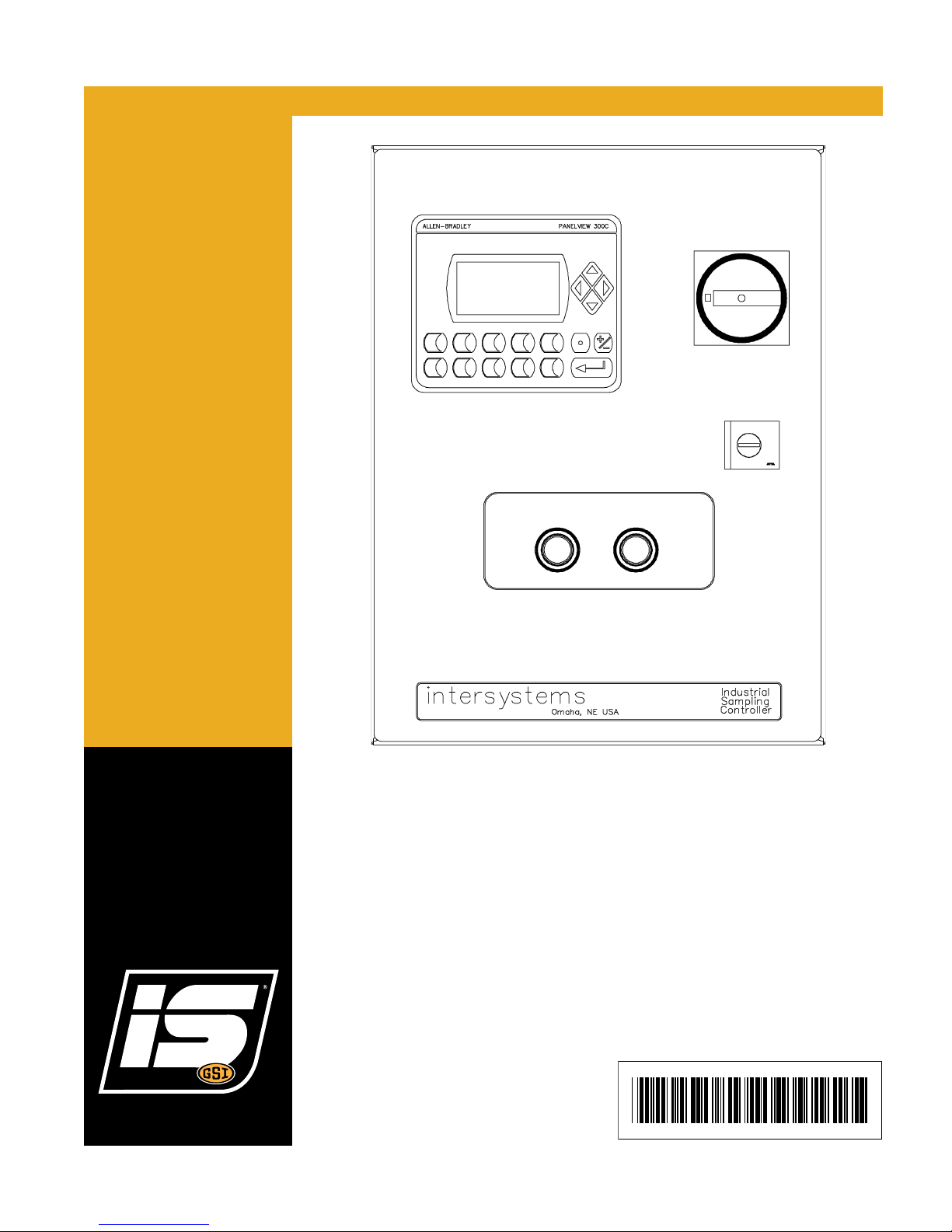
PLC Controller
PNEG-2170
Installation and Operation Manual
PNEG-2170
Version: 1.0
Date: 12-07-17
Page 2

All information, illustrations, photos, and specifications in this manual are based on the latest
information available at the time of publication. The right is reserved to make changes at any
time without notice.
2 PNEG-2170 PLC Controller
Page 3

Table of Contents
Contents
Chapter 1 Introduction ..........................................................................................................................................5
General Safety Statements ................................................................................................................... 5
Scope ..................................... ............................................................................................................... 6
Ordering Parts ....................................................................................................................................... 6
Replacement Parts ....................... .... ... ... ... ... .... .......................................... ... ... ... .... ... ... ........................ 6
Chapter 2 General Information .............................................................................................................................7
System Description .......................................................... ... ... .......................................... ..................... 7
Optional Features ................... ... ... .... .......................................... ... ... ... .................................................. 7
Chapter 3 Safety .....................................................................................................................................................8
Safety Guidelines .................................................................................................................................. 8
Cautionary Symbol Definitions ............................................... .... ... ... ... ... .... ... ... ..................................... 9
Safety Cautions ................................... ... ... .......................................... ... .... ... ...................................... 10
Safety Sign-Off Sheet ......................................................................................................................... 13
Chapter 4 Installation ..........................................................................................................................................14
Receiving Inspection . ... ... .................................................................................................................... 14
Pre-Installation Preparation .................................... .................... ................... ................... ................... 14
Controller Location .............................................................................................................................. 14
System Wiring ..................................................... ... ... .... ... ... ... ............................................................. 14
Chapter 5 Operations and Adjustments ............................................................................................................15
Control Components and their Functions ............................................................................................ 15
Chapter 6 Operations Mode and Description ............................. ...................................................... .................20
Operation Modes .................... ... ... .... ... .......................................... ... ... ... ............................................. 20
Chapter 7 PLC Settings for PS, PS-XP and HD-PP Sampler Operation ..........................................................24
Sampler Operation Description ........................................................................................................... 24
PS, PS-XP and HD-PP Sampler Operating Components ................................................................... 24
PS, PS-XP and HD-PP Sampler Program Mode ................................................................................ 24
PS, PS-XP and HD-PP Sampler Timer Settings ................................................................................. 25
Chapter 8 PLC Settings for PT, PTG, LF, GS, GP and PDP Sampler Operation ............................................26
Sampler Operation Description ........................................................................................................... 26
PT, PTG, LF, GS, GP and PDP Sampler Operating Components ...... ....................... ................... ...... 26
PT, PTG, LF, GS, GP and PDP Sampler Main Fuse (Refer to Certified Drawing) ............................. 26
PT, PTG, LF, GS, GP and PDP Sampler Program Mode ................................................................... 26
PT, PTG, LF, GS, GP and PDP Sampler Timer Settings ........... ................... ................... ................... 27
Chapter 9 PLC Settings for GSS and GSS-U Sampler Operation .......................... ............................. .............28
Sampler Operation Description ........................................................................................................... 28
GSS and GSS-U Sampler Operating Components ............................................................................. 28
GSS and GSS-U Sampler Main Fuse (Refer to Certified Drawing) .................................................... 28
GSS and GSS-U Sampler Program Mode .......................................................................................... 28
GSS and GSS-U Sampler Timer Settings ........................................................................................... 29
Chapter 10 PLC Settings for GT, GRES and RS Sampler Operation ....................... ... ... .... ... ... ... ... .... ... ..........30
Sampler Operation Description ......................................................................................................... 30
GT, GRES and RS Sampler Operating Components ........................................................................ 30
GT, GRES and RS Sampler Main Fuse (Refer to Certified Drawings) .............................................. 30
GT, GRES and RS Sampler Program Mode ..................................................................................... 30
PNEG-2170 PLC Controller 3
Page 4

Table of Contents
Chapter 11 PLC Settings for PRT and HD-PRT Sampler Operation ................................................................31
Sampler Operation Description ....................................... ... ... .... ... ... ... ... .... ... ... ... ............................... 31
PRT and HD-PRT Sampler Operating Components ......................................................................... 31
PRT and HD-PRT Sampler Main Fuse (Refer to Certified Drawing) ................................................. 31
PRT and HD-PRT Sampler Program Mode and Solenoid Timer ....................................................... 31
Chapter 12 PLC Settings for GRA and GCA Sampler Operation (550804) .....................................................33
Sampler Operation Description ....................................... ... ... .... ... ... ... ... .... ... ... ... ............................... 33
GRA and GCA Sampler Operating Components .............................................................................. 33
GRA and GCA Sampler Main Fuse (Refer to Certified Drawing) ...................................................... 33
GRA and GCA Sampler Program Mode ............. ... ... .... ... ... ... .... ... ... ... ... .... ... ... ... .... ... ........................ 33
Chapter 13 PLC Settings for GPE Sampler Operation (550804) ......................................................................34
Sampler Operation Description ....................................... ... ... .... ... ... ... ... .... ... ... ... ............................... 34
GPE Sampler Operating Components .............................................................................................. 34
GPE Sampler Program Mode ............................................................................................................ 34
Chapter 14 PLC Settings for Index Cabinet and Other Options ................................ ... ... .... ... ... ... ... .... ... ... ......35
Setting Controller to Operate Index Cabinet and Setting Up Index Cabinet ...................................... 35
Index Cabinet Delay Before Indexing ................................................................................................ 35
Sample Purge Option ........................................................................................................................ 36
Remote Enable .................................................................................................................................. 37
Chapter 15 Maintenance and Repair ..................................................................................................................38
General Maintenance ........................................................................................................................ 38
Periodic Inspection ............................................................................................................................ 38
Chapter 16 Troubleshooting ...............................................................................................................................39
PLC Control Troubleshooting ................ ... ... .... ... ... ... .... ... ... ... .... ......................................... .... ........... 39
Chapter 17 Warranty ............................................................................................................................................41
4 PNEG-2170 PLC Controller
Page 5
1. Introduction
This equipment is to be obtained only on the voltage designated on the certified
electrical drawings. Fire or explosion may result, which can cause death, serious
injury and extensive damage to equipment. Do not connect to voltages other than
designated.
Compressed air can cause severe injury. Shut off and lock out compressed air
source to the sampler and bleed off any and all present compressed air within the
sampler pneumatics before attempting any service on this sampler.
This manual covers the installation and operation for the PLC Con troller. This manual provides guidelines
for installing the product. You must retain a qualified contractor to provide on-site expertise.
INTERSYSTEMS IS NOT RESPONSIBLE FOR THE INSTALLATION OF THIS PRODUCT.
InterSystems reserves the right to improve its product whenever possible and practical to do so. We
reserve the right to change, improve and modify products at any time without obligation to ma ke changes,
improvements and modifications on equipment sold previously.
General Safety Statements
1. The PLC Controller is designed and manufactured with operator safety in mind. However, residual
hazards remain due to the nature of material handling, and specific material hazards. Use extreme
caution at all times.
2. Modifications to equipment may cause extremely dangerous situations that could result in damage
to the equipment as well as serious injury or death. Never modify the equipment.
3. Intersystems recommends that you contact the local power company to have a representative survey
the installation to ensure wiring is compatible with their system and adequate power is supplied to
the unit.
4. Consult Intersystems before making any changes to the sampler or its operating environment.
Careless changes could result in death or serious injury to people and reduce the performance and
service life of the equipment.
5. Never perform any service on this equipment or any powered equipment until all power has been
shut off and locked out so that it cannot be restored without the consent and knowledge of the person
who interrupted power. Power includes electrical, fluid, mechanical or pneumatic energy.
6. Never perform any service on this equipment without utilizing the required PPE (Personal Protective
Equipment). Refer to the MSDS (s) (Material Safety Data Sheet (s)), on all products to which this
equipment is in contact to determine what PPE is required.
PNEG-2170 PLC Controller 5
Page 6

1. Introduction
Scope
The certified drawings list the non-standard components that have been incorporated into the equipment.
InterSystems, Inc. normally stocks non-fabricated parts and non-custom OEM parts. Replacement parts
for any other components, including fabricated parts and custom OEM components can be supplied
upon request.
Ordering Parts
Direct parts orders or requests for technical assistance to your sales representative or to:
InterSystems, Inc.
9575 No 109
Omaha, NE 68142
Phone: (402) 330-1500
FAX: (402) 330-3350
Please have available the MODEL NUMBER, SERIAL NUMBER and CUSTOMER ORDER NUMBER of
the equipment in question as well as the location where the sampler is INSTALLED.
th
Ave
Replacement Parts
The InterSystems, Inc. sampler is a quality built piece of machinery. As with any machine, parts do wear
out and fail. It is InterSystem’s recommendation that a small supply of spare parts be kept on hand to cover
any minor breakdowns. A separate priced spare parts list will be sent identifying the suggested spare
parts. It is also necessary to check the certified drawings, which will list a ny special or custom components
utilized on this equipment.
6 PNEG-2170 PLC Controller
Page 7

2. General Information
System Description
The PLC control is an Allen Bradley Micologix 10 point processor interfaced with a PanelView 300
operator display designed to control one sampler at a time. The control can handle the addition of a
collection cabinet at installation or at a later date without replacing or upgrading the control. The controller
was design with the intent to be user friendly using a minimum number of key strokes.
Sampler start-up, setting and operator interaction are easily navigated through the menu screens on the
PanelView screen. Once the control is set-up and the desired timer values entered, the control can be set
to run in automatic or manual operation. When in automatic mode, the control will upon initial power up
wait 30 seconds before beginning the automatic sequence. This is designed to allow the operator time to
decide if they want automatic or manual operation. If the control has been ON and the remote enable
signal is use the 30 second delay is not used. When the control is in automatic, the delay between samples
timer will start to time down, upon reaching 0 the control will begin the desired sampling sequence. When
the control is set for manual operation, the delay between samples timer is ignored and upon press the
“F1” key, the sampler will begin the sampling sequence.
Optional Features
The certified drawings indicate which, if any, optional features are included with a sampler control. Some
of the more frequently specified optional features are briefly described in the following list.
1. Controller arranged to initiate a sampling cycle based on quantity or volume of material passing
through conveying line rather than upon elapsed time periods.
2. Explosion Proof Controller. There are several major differences in an explosion-proof control as
compared to a standard control. An explosion proof control will typically have the following features.
The explosion proof sampler control is available in two enclosure classifications.
a. The NEMA 9 control with the rating of:
Class 2, Groups E, F and G, Division 1 and 2
b. The NEMA 7 control with the rating of:
Class 1, Groups C and D, Division 1 and 2
Class 2, Groups E, F and G, Division 1 and 2
3. Enclosure components of special materials, such as 304 stainless steel.
PNEG-2170 PLC Controller 7
Page 8

3. Safety
ST-0001-3
Safety Guidelines
Safety guidelines are general-to-specific safety rules that must be followed at all times. This manual is
written to help you understand safe operating procedures and problems that can be encountered by the
operator and other personnel when using this equipment. Save these safety guidelines for future
reference.
As owner or operator, you are responsible for understanding the requirements, hazards, and precautions
that exist and to inform others as required. Unqualified persons must stay out of the work area at all times.
Alterations must not be made to the equipment. Alterations can produce dangerous situations resulting in
SERIOUS INJURY or DEATH.
This equipment must be installed in accordance with the current installation codes and applicable
regulations, which must be carefully followed in all cases. Authorities having jurisdiction must be consulted
before installations are made.
When necessary, you must consider the installation location relative to electrical, fuel and water utilities.
Personnel operating or working around equipment must read this manual. This manual must be delivered
with equipment to its owner. Failure to read this manual and its safety instructions is a misuse of the
equipment.
8 PNEG-2170 PLC Controller
Page 9
3. Safety
This symbol indicates an imminently hazardous situation
which, if not avoided, will result in serious injury or death.
This symbol indicates a potentially hazardous situation
which, if not avoided, can result in serious injury or death.
This symbol indicates a potentially hazardous situation which,
if not avoided, can result in minor or moderate injury.
This symbol is used to address practices not related to
personal injury.
This symbol indicates a general hazard.
This symbol indicates a prohibited activity.
This symbol indicates a mandatory action.
ST-0005-2
Cautionary Symbol Definitions
Cautionary symbols appear in this manual and on product decals. The symbols alert the user of potentia l
safety hazards, prohibited activities and mandatory actions. To help you recognize this information, we
use the symbols that are defined below.
DANGER
WARNING
CAUTION
NOTICE
PNEG-2170 PLC Controller 9
Page 10
3. Safety
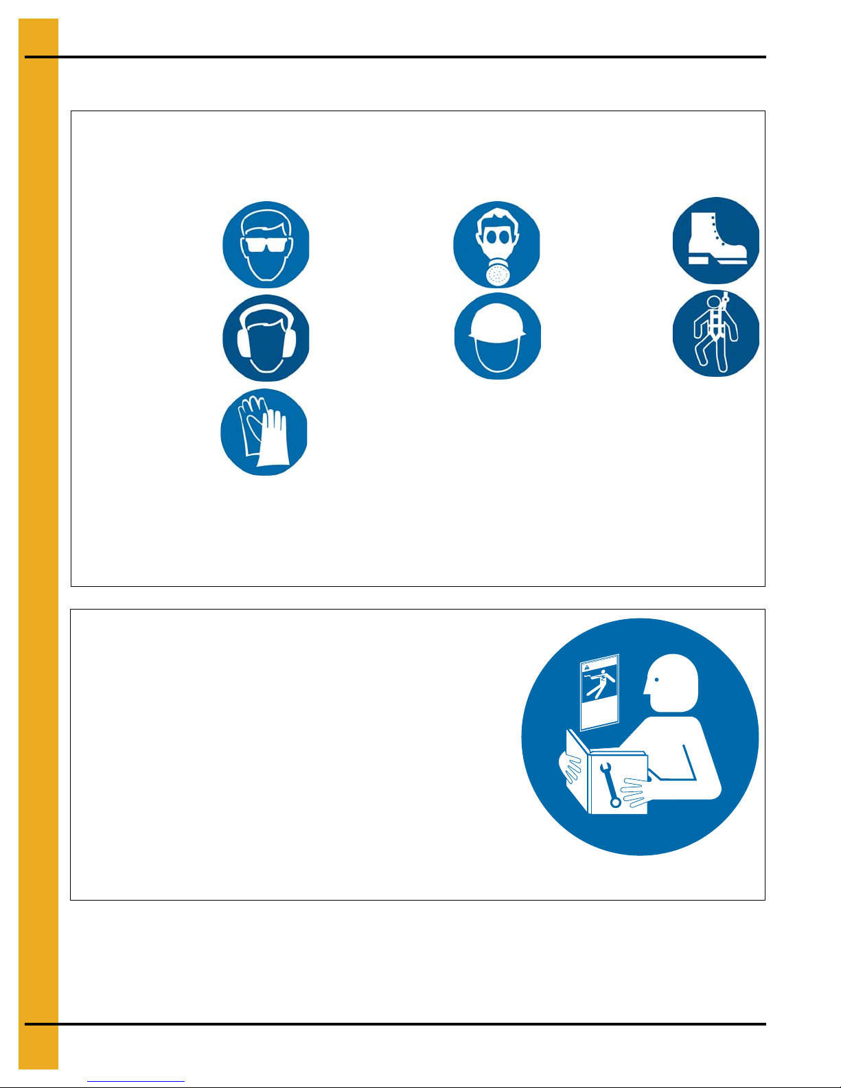
Use Personal Protective Equipment
Eye
Protection
Hearing
Protection
Hand
Protection
Head
Protection
Respiratory
Protection
Foot
Protection
Fall
Protection
• Use appropriate personal protective equipment:
• Wear clothing appropriate to the job.
• Remove all jewelry.
• Tie long hair up and back.
ST-0004-1
Follow Safety Instructions
• Carefully read all safety messages in this manual and
safety signs on your machine. Keep signs in good
condition. Replace missing or damaged safety signs.
Be sure new equipment components and repair parts
include the current safety signs. Replacement safety
signs are available from the manufacturer.
• Learn how to operate the machine and how to use
controls properly. Do not let anyone operate without
instruction.
• If you do not understand any part of this manual or
need assistance, contact your dealer.
ST-0002-1
Safety Cautions
10 PNEG-2170 PLC Controller
Page 11
3. Safety
Maintain Equipment and Work Area
• Understand service procedures before doing work. Keep area
clean and dry.
• Never service equipment while it is operating. Keep hands, feet,
and clothing away from moving parts
• Keep your equipment in proper working condition. Replace worn
or broken parts immediately.
ST-0003-1
Stay Clear of Hoisted Equipment
• Always use proper lifting or hoisting equipment when assembling
or disassembling equipment.
• Do not walk or stand under hoisted equipment.
• Always use sturdy and stable supports when needed for
installation. Not following these safety precautions creates the
risk of falling equipment, which could crush personnel and cause
serious injury or death.
ST-0047-1
Sharp Edge Hazard
• This product has sharp edges, which can cause serious injury.
• To avoid injury, handle sharp edges with caution and always use
proper protective clothing and equipment
ST-0036-2
Install and Operate Electrical Equipment Properly
• Electrical controls must be installed by a qualified electrician and
must meet the standards set by applicable local codes (National
Electrical Code for the US, Canadian Electric Code, or EN60204
along with applicable European Directives for Europe).
• Lock-out power source before making adjustments, cleaning, or
maintaining equipment.
• Make sure all equipment is properly grounded.
ST-0027-4
PNEG-2170 PLC Controller 11
Page 12
3. Safety
Stay Clear of Moving Parts
• Stay clear - machine can start without warning.
• Entanglement in gate will cause serious injury.
• Keep all shields and covers in place at all times.
• Lock-out power source before making adjustments, cleaning, or
maintaining equipment.
ST-0070-1
Stay Clear of Rotating Parts
• Do not service equipment while it is in operation.
• Entanglement in rotating parts or exposed belts will cause serious
injury or death.
• Keep all shields and covers in place at all times.
• Lock-out power source before making adjustments, cleaning,
or maintaining equipment.
ST-0072-1
12 PNEG-2170 PLC Controller
Page 13
3. Safety
Flying Material and High Pressure Air Hazard
• Flying material and/or high pressure air can cause
severe eye injury or blindness.
• Wear safety glasses around operating equipment.
ST-0071-1
Safety Sign-Off Sheet
Below is a sign-off sheet that can be used to verify that all person nel have read and understood the safety
instructions. This sign-off sheet is provided for your convenience and personal record keeping.
Date Employee Name Supervisor Name
PNEG-2170 PLC Controller 13
ST-0007
Page 14

4. Installation
Receiving Inspection
Carefully inspect the sampler control for damage as soon as it is received. Also, verify that the quantity of
parts or packages actually received corresponds to the quantity shown on the packing slip. Report any
damage or shortage to the delivering carrier as soon as possible. InterSystem’s responsibility for the
equipment ended with acceptance by the delivering carrier. Refer to the bill of lading.
Pre-Installation Preparation
NOTE: Before starting the sampling system installation, study this manual, the certified drawing(s)
furnished with the system and other applicable documents (including, but not limited to OSHA
regulations, the National Electrical Code and all other applicable federal, state and local codes
and regulations).
Controller Location
1. Use vibration isolation pads when mounting the control enclosure or mount the controller in a
vibration free location.
2. Unless ordered for severe duty, locate controller so it is protected from water and dust.
3. Unless an explosion-proof rated controller was specifically ordered, DO NOT locate the controlle r in
a hazardous area.
4. Most applications require that the sampler be in easy view of the controller.
System Wiring
Refer to the certified electrical drawing(s) for specific wiring requirements. The 19-position barrier
terminal strip located inside the bottom right corner of the control enclosure is the connection point for
ALL external circuitry.
The controller was completely assembled and tested with the sampler before it left the factory. The
electrical installation must comply with OSHA Regulations, the National Electrical Code and all other
applicable federal, state and local codes and regulations.
If wiring between the controller and the sampler unit is run through rigid conduit, use a short length of
flexible conduit to connect wiring to the sampler. This will isolate the rigid conduit from any vibration
originating in the product conveying line and sampler.
Controller Electrical Power Requirements
110/120 VAC 50/60 Hz, Single Phase, 20 Amp Maximum Service.
Optional - 220/240 VAC 50/60 Hz, Single Phase, 10 Amp Service.
Refer to the certified electrical drawing(s) for specific wiring requirements. InterSystems strongly
recommends that electrical service to the sampling system be an isolated line. Voltage fluctuations and
line noise can affect the controller, thus causing the sampler to malfunction.
14 PNEG-2170 PLC Controller
Page 15

Control Components and their Functions
5. Operations and Adjustments
Figure 5A Standard Nema 4 Control Panel Detail
Refer to the certified electrical drawing(s) for dimensions on control panels with optional features.
PNEG-2170 PLC Controller 15
Page 16

5. Operations and Adjustments
This machine starts without warning. Moving parts can cause severe
injury. Clear area prior to controller start-up.
Power OFF/ON Switch S-1
The Power OFF/ON switch controls all electrical power to the controller and the sampler unit.
Power Pilot Light
This light is illuminated as long as power is available to the controller and the POWER switch (S-1) is set
to ON.
Sampling Pilot Light
This light will illuminate when a sampling cycle has been initiated and will stay lit until CR-1 has been
turned OFF for controller series 550800. On control series 550803 the sampling lights are associated
with the traverse direction of the pelican. The light will stay illuminated until the solenoid has been
de-engerized.
PanelView 300 Operator Interface
The operator interface is the source of all input necessary to operate the control. The operator PanelView
is setup using linked menus to step through the operation of the control. The following flow chart depicts
the layout of the operator menus. (See chart on Page 17.)
16 PNEG-2170 PLC Controller
Page 17

5. Operations and Adjustments
PNEG-2170 PLC Controller 17
Figure 5B Operator PanelView Flow Chart
Page 18

5. Operations and Adjustments
F1 MANUAL SAMPLE
F2 MANUAL INDEX
F3 IN MANUAL
F4 SETTINGS
F1 VIEW SETTINGS
F2 SAMPLER TIMER
F3 SAMPLE SELECTION
F4 MAIN SCREEN
F1 PROGRAM MODE
F2 OPTION SETTINGS
F4 MAIN SCREEN
F1 OPERAT ION MODE
F2 INDEXER SETUP
F3 PURGE OFF
F4 PASSWORD SCREEN
Description of Operator Screens
Function keys F1, F2, F3 and F4
Up/Down arrow keys
Left/right arrow keys Used to change numeric number position.
F1 MANUAL SAMPLE
F2 MANUAL INDEX
F3 IN MANUAL
F4 SETTINGS Allows user to select other control options.
F1 VIEW SETTINGS
Used to select desired control function or
parameters.
Used to enter numeric numbers by incrementing
digits.
Enter key
Used to initial a manual sample cycle when in
manual mode.
Used to initial a manual index of sample cabinet in
manual mode when a cabinet is connected to the
control.
F3 toggles between manual mode and automatic
mode.
Used to view sample duration timer.
F1 TIME BETWEEN SAMPLES
F2 SAMPLES DONE
F3 CURRENT JAR
F4 INPUT STATUS and TURN OUTPUT ON
F2 SAMPLE TIMER
F3 SAMPLE SELECTION
F1 PROGRAM MODE
F2 OPTION SETTINGS
F1 OPERATION MODE
F2 INDEXER SETUP
F3 PURGE OFF Turns sample purge ON/OFF.
Password required for changing time between
samples.
Allows operator to select program mode and option
settings.
Changes between the different sampler programs
in the controller.
F1 toggles through sampler programs.
F2 sets timer values for that specific sampler.
Allows operator to change mode of operation, turn
ON and set-up index cabinet and turn on sample
purge.
Changes control operation from timer based to
counter and timer/counter.
Also contains the Timer Settings to allow for the
adjustment of the specific sampler timer values.
Used to turn the indexer ON or OFF, enter the total
number of jars per cabinet and enter the number of
samples per jar.
18 PNEG-2170 PLC Controller
Page 19

5. Operations and Adjustments
This control is to be operated only on the voltage designated on the certified
electrical drawing. Fire or explosion may result, which can cause death, serious
injury and extensive damage to equipment.
Terminal Strip
This 19-position barrier terminal strip is located inside along the bottom right corner of the control
enclosure. It serves as the controller’s interface and connection point for all external circuits and for the
components mounted in the enclosure. Refer to the certified electrical drawing(s).
Power Transformer
The control is equipped with a transformer which converts 120/240 volt incoming power to 24 VDC f or the
operation of the PLC, PanelView, display lights, input signals and operation of the control relays. Refer to
the certified electrical drawing(s). The transformer is internally protected against overloads.
Control Relays
The control is equipped with four control relays, which are driven by the PLC output signals. Each relay
has a mechanical flag indicator showing the relay is energized. The relay coil is operated using 24 VDC
while the relay contacts are wired for 120/240 volts. Refer to the certified electrical drawing(s).
Main Fuse F1
This fuse is located along the top edge of the control next to the base of the ON/OFF switch. The fuse
rating will change depending on the type of sampler being used. This fuse protects the controller and
sampler components against overloads and short circuits.
For 120/240 VAC, 1 PH operation use ONLY a Buss Type FNM, 250 Volt Slo-Blo fuse or equal.
Microview PLC
The PLC for the control is a 10 point Allen Bradley Microview controller. The PLC operates on 24 VDC and
is pre-wired to the proper terminal strip inputs and outputs. The processor program is protected to prevent
any alterations to the existing program. This control is design only to run InterSystems equipment.
PNEG-2170 PLC Controller 19
Page 20

6. Operations Mode and Description
Operation Modes
The PLC control can operate under three different operation modes: Timer, Counter, Counter/Counter,
Timer/Counter. Operation mode determines when the sampler starts a sample cycle when in the
automatic mode. The controls are factory set in the Timer operation mode.
Counter Mode
When in the COUNTER mode the sampler is looking for pulses from external equipment (i.e. bagging line).
When the sampler reaches the desired counts a sample cycle will be initiated. To set the control to operate
in COUNTER mode:
1. Turn power ON.
2. Press F4 key for Settings.
3. Press F3 for Sample Selection.
4. If prompted for the User enter 1 followed by enter key .
5. Enter Password screen will appear. Using the Up/Down arrow keys on the right side to adjust number
values and the Left/Right arrow keys on the left side to change position enter 1500 followed by the
enter key .
6. Caution Changing Sampler Parameters press F3 for OK.
7. Press F2 for Option Settings.
8. Press F1 for Operation Mode.
9. Press F1 to toggle through to counter.
10. Press F2 to change the number of counts between samples.
11. Enter desired value using the Up/Down arrow keys on the right side to adjust number values and the
Right/Left arrow keys on the left side to change position. Then press the Enter key .
12. Press F4 to return to Main Screen.
To initiate the input pulse the factory installed REMOTE ENABLE jumper needs to be removed. In its
place, install a normally open contact. The normally open contact should be a dry contact rated for
120 VAC 0.5 Amps. This contact needs to be driven by the customer’s process (i.e. bagging line). When
the contact closes the sampler PLC will register a count. They will count up until the desired count value
is reached. When the count value is reached the sampling cycle will begin.
Signal Start-Multiple Cycle Mode
When in the Signal Start-Multiple Cycle mode the sampler is lookin g for a pulse from exte rnal equ ipment
(i.e. bagging line). When the enable signal is initiated the sampler will cycle for a pre-determined nu mber
of cycles. To set the control to operate in Signal Start-Multiple Cycle mode:
1. Turn power ON.
2. Press F4 key for Settings.
3. Press F3 for Sample Selection.
4. If prompted for the User enter 1 followed by enter key .
20 PNEG-2170 PLC Controller
Page 21

6. Operations Mode and Description
5. Enter Password screen will appear. Using the Up/Down arrow keys on the right side to adjust number
values and the Left/Right arrow keys on the left side to change position enter 1500 followed by the
enter key .
6. Caution Changing Sampler Parameters press F3 for OK.
7. Press F2 for Option Settings.
8. Press F1 for Operation Mode.
9. Press F1 to toggle through to Enable/X samples.
10. Press F2 to change the number of sample counts required.
11. Enter desired value using the Up/Down arrow keys on the right side to adjust number values and the
Right/Left arrow keys on the left side to change position. Then press the Enter key .
12. Press F3 to change the time between samples (in seconds).
13. Enter desired value using the Up/Down arrow keys on the right side to adjust number values and the
Right/Left arrow keys on the left side to change position. Then press the Enter key .
14. Press F4 to return to Main.
To initiate the input pulse, remove the factory installed REMOTE ENABLE jumper. In its place, install a
normally open dry contact rated for 120 VAC 0.5 Amps that is driven by the customer’s process
(i.e: bagging line). When the contact closes the sampler PLC will start the sampling cycle. When the
sample cycles are complete, the control will require another input pulse to start the cycle over.
Timer Mode
When in the Timer mode the sampler will time down in hours, minutes or seconds. Wh en the timer reaches
0 the sampling cycle will begin. To set the control to operate in TIMER mode:
1. Turn power ON.
2. Press F4 key for Settings.
3. Press F3 for Sample Selection.
4. If prompted for the User enter 1 followed by enter key .
5. Enter Password screen will appear. Using the Up/Down arrow keys on the right side to adjust number
values and the Left/Right arrow keys on the left side to change position enter 1500 followed by the
enter key .
6. Caution Changing Sampler Parameters press F3 for OK.
7. Press F2 for Option Settings.
8. Press F1 for Operation Mode.
9. Press F1 to toggle through to Timer.
10. Press F4 to return to Main Screen.
When in automatic mode, the REMOTE ENABLE jumper needs to be installed. NOTE: When in manual
mode, the sampler will only take one sample per incident.
PNEG-2170 PLC Controller 21
Page 22

6. Operations Mode and Description
Changing the sampling frequency between sampler cycles is accomplished by following the instructions
below. This time value can be set for the maximum time of 9999 hours, 59 minutes and 59 seconds. To
change the program mode follow the instructions below:
1. Turn power ON.
2. Press F4 key for Settings.
3. Press F2 for Sample Timer.
4. Press F3 for Change Time.
5. Press F1 for Hours.
6. Press F2 for Minutes.
7. Press F3 for Seconds.
8. Using the Up/Down and Right/Left arrow keys to set the correct Time. Once the correct time value
has been entered, press the enter key .
9. Press F4 to return to Previous Screen.
10. Press F4 for Main Screen.
Timer/Counter Mode
When in the Timer/Counter mode the sampler will time down in hours, minutes or seconds. When the timer
reaches 0 the sampling cycle will take the number of samples entered into the counter. To set the control
to operate in TIMER/COUNTER mode:
1. Turn power ON.
2. Press F4 key for Settings.
3. Press F3 for Sample Selection.
4. If prompted for the User enter 1 followed by enter key .
5. Enter Password screen will appear. Using the Up/Down arrow keys on the right side to adjust number
values and the Left/Right arrow keys on the left side to change position enter 1500 followed by the
enter key .
6. Caution Changing Sampler Parameters press F3 for OK.
7. Press F2 for Option Settings.
8. Press F1 for Operation Mode.
9. Press F1 to toggle through to Time/X samples.
10. Press F2 to change the number of sample counts required.
11. Enter desired value using the Up/Down arrow keys on the right side to adjust number values and the
Right/Left arrow keys on the left side to change position. Then press the Enter key .
12. Press F3 to change the time between samples (in seconds).
13. Enter desired value using the Up/Down arrow keys on the right side to adjust number values and the
Right/Left arrow keys on the left side to change position. Then press the Enter key .
14. Press F4 to return to Main.
22 PNEG-2170 PLC Controller
Page 23

6. Operations Mode and Description
Changing the sampling frequency between sampler cycles is accomplished by following the instructions
below. This time value can be set for the maximum time of 999 hours, 59 minutes and 59 seconds.
To change the program mode follow the instructions below:
1. Turn power ON.
2. Press F4 key for Settings.
3. Press F2 for Sample Timer.
4. Press F3 for Change Time.
5. Press F1 for Hours.
6. Press F2 for Minutes.
7. Press F3 for Seconds.
8. Using the Up/Down and Right/Left arrow keys to set the correct Time. Once the correct time value
has been entered, press the enter key .
9. Press F4 to return to Previous Screen.
10. Press F4 for Main Screen.
When in automatic mode, the REMOTE ENABLE jumper needs to be installed. NOTE: When in manual
mode, the sampler will only take one sampler per incident.
PNEG-2170 PLC Controller 23
Page 24

7. PLC Settings for PS, PS-XP and HD-PP Sampler Operation
Sampler Operation Description
The PS style sampler when operated in the timing mode and Automatic operates as follows. When the
illuminated display reads all zeroes (000), the timer has “timed out” and initiates a sampling cycle. The
sample probe extends and delays to collect a sample until T1 times out, the probe then retracts and
actuates the limit switch LS-1. After the limit switch close and a delay of 1/2 second (to allow the bevel
gears to mesh) the auger motor is energized for the time setting of T2. After timer T2 times out, the motor
will stop and the timer display resets to the preset value and another timing interval is initiated. If the
controller is shut off or the mode switched from AUTO to MANUAL, the timing cycle is te rmin ated. When
power is restored or the AUTO mode is again selected, the display is reset to the preset value and another
cycle begins. NOTE: A new timing cycle can be initiated ONLY after the sampling cycle has completed.
PS, PS-XP and HD-PP Sampler Operating Components
The PS, PS-XP and HD-PP style samplers have three main operating components: solenoid valve to
extend the sample probe, limit switch to ensure proper gear mesh and the auger motor. Refer to the
certified drawing(s).
PS Sampler Main Fuse (Refer to Certified Drawing)
For 110/120 VAC, 1 PH operation use ONLY a Buss Type FNM 5 Amp, 250 volt Slo-Blo fuse or equal.
For 220/240 VAC, 1 PH operation use ONLY a Buss Type FNM 3 Amp, 250 volt Slo-Blo fuse or equal.
PS-XP Sampler Main Fuse (Refer to Certified Drawing)
For 110/120 VAC, 1 PH operation use ONLY a Buss Type FNM 15 Amp, 250 volt Slo-Blo fuse or equal.
For 220/240 VAC, 1 PH operation use ONLY a Buss Type FNM 8 Amp, 250 volt Slo-Blo fuse or equal.
HD-PP Sampler Main Fuse (Refer to Certified Drawing)
For 110/120 VAC, 1 PH operation use ONLY a Buss Type FNM 15 Amp, 250 volt Slo-Blo fuse or equal.
For 220/240 VAC, 1 PH operation use ONLY a Buss Type FNM 8 Amp, 250 volt Slo-Blo fuse or equal.
PS, PS-XP and HD-PP Sampler Program Mode
The PS, PS-XP and HD-PP style sampler must be set to run on Program Mode 0 only. To change the
program mode follow the instructions below:
1. Turn power ON.
2. Press F4 key for Settings.
3. Press F3 for Sample Selection.
4. If prompted for the User enter 1 followed by enter key .
5. Enter Password screen will appear. Using the Up/Down arrow keys on the right side to adjust number
values and the Left/Right arrow keys on the left side to change position enter 1500 followed by the
enter key .
6. Caution Changing Sampler Parameters press F3 for OK.
7. Press F1 for Program Mode.
24 PNEG-2170 PLC Controller
Page 25

7. PLC Settings for PS, PS-XP and HD-PP Sampler Operation
8. Press F1 for Mode (the current sampler mode sho uld be showing). To change samp ler mode, press
F1 until a 0 is showing on this line.
9. Press F2 to change the sampler timer settings. (Extend timer and auger run timer.) The current value
should be showing on the right side of this line. See PS and PS-XP and HD-PP chart for correct timer
settings.
10. Press F1 to change the Solenoid time in seconds.
11. Using the Up/Down and Right/Left arrow keys to set the correct solenoid time. See PS and PS-XP
and HD-PP chart for the correct timer setting. Once the correct time value has been entered, press
the enter key .
12. Press F2 to change the Auger run time in seconds. The current value should be showing on the right
side of this line. See PS and PS-XP and HD-PP chart for correct timer setting.
13. Using the Up/Down and Right/Left arrow keys to set the correct auge r time. See PS and PS-XP and
HD-PP chart for the correct timer setting. Once the correct time value has been entered, press the
enter key .
14. Press F4 to return to Password Screen.
15. Press F4 to return to Main Screen.
PS, PS-XP and HD-PP Sampler Timer Settings
The PS, PS-XP and HD-PP style sampler has two timer setting which must be set for proper operation.
The two timers are solenoid extend time (T1) and auger motor run timer (T2). See PS and PS-XP and
HD-PP chart for recommended settings.
PS and PS-XP
Sampler Size PS-4 PS-6 PS-8 PS-10 PS-12 PS-14 PS-16
Solenoid Time (Seconds) T1 2 3 3 3 4 4 4
Motor Time (Seconds) T2 8 8 10 12 14 14 16
HD-PP
Sampler Size HD-PP-6 HD-PP-8 HD-PP-10 HD-PP-12 HD-PP-14 HD-PP-16
Solenoid Time (Seconds) T1 3 3 4 4 5 5
Motor Time (Seconds) T2 8 10 12 14 14 16
NOTE: Solenoid valve time is to be adjusted so that the sample tube e xtends into the product stream only
long enough to allow a representative sample to be collected. Extending the sample tube into the
product stream for excessively
and can result in clogging of product flowing through the conveying line.
long periods of time can result in unnecessary sample tube wear
NOTE: Motor run time is to be adjusted to allow the auger to clean out the sa mple tube at the end of each
cycle. Minimum run time will depend on the characteristics of the ma terial being sampled and may
well require re-adjustment if the product being sampled changes.
PNEG-2170 PLC Controller 25
Page 26

8. PLC Settings for PT, PTG, LF, GS, GP and PDP Sampler Operation
Sampler Operation Description
The PT style sampler when operated in the timing mode and Automatic operates as follows. When the
AUTO mode is selected, the timer begins timing down. When the illuminated display reads all zeroes
(000), the timer has “timed out” and initiates a sampling cycle. The sample probe extends and delays to
collect a sample until T1 times out, the probe then retracts. The timer display resets to the preset value
and another timing interval is initiated. If the controller is shut off or the mode switched from AUTO to
MANUAL, the timing cycle is terminated. When power is restored or the AUTO mode is again selected,
the display is reset to the preset value and another cycle begins. NOTE: A new timing cycle can be initiated
ONLY after the sampling cycle has completed.
PT, PTG, LF, GS, GP and PDP Sampler Operating Components
The PT, PTG, LF, GS, GP style sampler has one main operating component, the solenoid valve to extend
the sample probe. Refer to the certified drawing(s).
PT, PTG, LF, GS, GP and PDP Sampler Main Fuse (Refer to
Certified Drawing)
For 110/120 VAC, 1 PH operation use ONLY a Buss Type FNM 2 Amp, 250 volt Slo-Blo fuse or equal.
For 220/240 VAC, 1 PH operation use ONLY a Buss Type FNM 1 Amp, 250 volt Slo-Blo fuse or equal.
PT, PTG, LF, GS, GP and PDP Sampler Program Mode
The PT, PTG, LF, GS, GP style sampler must be set to run on Program Mode 1 only. To change the
program mode follow the instructions below:
1. Turn power ON.
2. Press F4 key for Settings.
3. Press F3 for Sample Selection.
4. If prompted for the User enter 1 followed by enter key .
5. Enter Password screen will appear. Using the Up/Down arrow keys on the right side to adjust number
values and the Left/Right arrow keys on the left side to change position enter 1500 followed by the
enter key .
6. Caution Changing Sampler Parameters press F3 for OK.
7. Press F1 for Program Mode.
8. Press F1 for Mode (the current sampler mode should be showing). To change sampler mode, pre ss
F1 until a 1 is showing on this line.
9. Press F2 to change the sampler timer setting. (Extend timer.) The current value should be showing
on the right side of this line. See chart on Page 27 for correct timer settings.
10. Press F1 to change the Solenoid time in seconds.
11. Using the Up/Down and Right/Left arrow keys to set the correct solenoid time. See chart on Page 27
for the correct timer setting. Once the correct time value has been entered, press the enter key
.
26 PNEG-2170 PLC Controller
Page 27

8. PLC Settings for PT, PTG, LF, GS, GP and PDP Sampler Operation
12. Press F4 to return to Password Screen.
13. Press F4 to return to Main Screen.
PT, PTG, LF, GS, GP and PDP Sampler Timer Settings
The PT, PTG, LF, GS, GP style sampler has one timer setting which must be set f or proper operation. The
timer setting is for the solenoid extend time (T1). See Chart for recommended settings.
Sampler Size PDP PT PTG LF GP GS
Solenoid Time (Seconds) T1 3 3 3 3 3 3
NOTE: Solenoid valve time is to be adjusted so that the sample tube e xtends into the product stream only
long enough to allow a representative sample to be collected and the desired sample size.
Extending the sample tube into the product stream for excessively
long periods of time can result
in unnecessary sample tube wear and can result in clogging of product flowing through the
conveying line and excessive sample size.
PNEG-2170 PLC Controller 27
Page 28

9. PLC Settings for GSS and GSS-U Sampler Operation
Sampler Operation Description
The GSS style sampler when operated in the timing mode and Automatic operates as follows. When the
AUTO mode is selected, the timer begins timing down. When the illuminated display reads all zeroes
(000), the timer has “timed out” and initiates a sampling cycle. The sample cycle begins when an electric
motor operating through a right angle gear reducer rotates the drive housing input shaft. Timer T1 is set
for the total time the motor will run. The clutch solenoid energizes at the same time allowing the auger tube
in the product line to rotate through one revolution to collect a sample. Timer T-2 is set long enough to
complete on revolution of the auger tube. As the auger tube rotates the sample auger also is turning and
continues to auger material out of the auger tube for a period of time after the auger tube stops rotating
and T1 times out. The timer display resets to the preset value and another timing interval is initiated. If the
controller is shut off or the mode switched from AUTO to MANUAL, the timing cycle is te rmin ated. When
power is restored or the AUTO mode is again selected, the display is reset to the preset value and another
cycle begins. NOTE: A new timing cycle can be initiated ONLY after the sampling cycle has completed.
GSS and GSS-U Sampler Operating Components
The GSS and GSS-U style sampler has three main operating components: the clutch solenoid to rotate
the auger tube, the sampler motor to rotate the sample auger and auger tube and a limit switch to stop the
tube rotation. Refer to the certified drawing(s).
GSS and GSS-U Sampler Main Fuse (Refer to Certified Drawing)
For 110/120 VAC, 1 PH operation use ONLY a Buss Type FNM 10 Amp, 250 volt Slo-Blo fuse or equal.
For 220/240 VAC, 1 PH operation use ONLY a Buss Type FNM 5 Amp, 250 volt Slo-Blo fuse or equal.
GSS and GSS-U Sampler Program Mode
The GSS and GSS-U style sampler must be set to run on Program Mode 2 only. To change the program
mode follow the instructions below:
1. Turn power ON.
2. Press F4 key for Settings.
3. Press F3 for Sample Selection.
4. If prompted for the User enter 1 followed by enter key .
5. Enter Password screen will appear. Using the Up/Down arrow keys on the right side to adjust number
values and the Left/Right arrow keys on the left side to change position enter 1500 followed by the
enter key .
6. Caution Changing Sampler Parameters, press F3 for OK.
7. Press F1 for Program Mode.
8. Press F1 for Mode (the current sampler mode should be showing). To change sampler mode, pre ss
F1 until a 2 is showing on this line.
9. Press F2 to change the sampler timer setting. (Solenoid timer and Motor run timer.) The current value
should be showing on the right side of this line. See Chart on Page 29 for correct timer settings.
10. Press F1 to change the Solenoid time in seconds.
28 PNEG-2170 PLC Controller
Page 29

9. PLC Settings for GSS and GSS-U Sampler Operation
11. Using the Up/Down and Right/Left arrow keys to set the correct solenoid time. See Chart for the
correct timer setting. Once the correct time value has been entered, press the enter key .
12. Press F2 to change the Motor run time in seconds. The current value should be showing on the right
side of this line. See Chart for correct timer setting.
13. Using the Up/Down and Right/Left arrow keys to set the correct auger time. See Chart for the correct
timer setting. Once the correct time value has been entered, press the enter key .
14. Press F4 to return to Password Screen.
15. Press F4 to return to Main Screen.
GSS and GSS-U Sampler Timer Settings
The GSS and GSS-U style sampler has two timer setting which must be set for proper operation.
The timer setting is for the solenoid clutch time (T1) and the motor time (T2). See Chart for recommended
settings.
Sampler Size Clutch Solenoid (T1) Motor Time (T2)
GSS and GGS-U Settings 4 25
NOTE: Clutch solenoid time is to be adjusted so that the auger tube makes one revolution. When this
timer times out the solenoid will stay energized until the limit switch is activated. The activation of
the limit switch will de-engergize the clutch solenoid stopping the auger tube. If additional
revolutions are desired, add 6 seconds to the clutch solenoid and motor timer settings for each
additional revolution.
PNEG-2170 PLC Controller 29
Page 30

10. PLC Settings for GT, GRES and RS Sampler Operation
Sampler Operation Description
The RS style sampler when operated in the timing mode and Automatic operates as follows. When the
AUTO mode is selected, the timer begins timing down. When the illuminated display reads all zeroes
(000), the timer has “timed out” and initiates a sampling cycle. An internal none adjustable timer starts the
sample cycle until the sampler limit switch contacts are closed. The sample cutter will make one complete
revolution to collect a sample until the limit switch contacts open, stopping the cycle. The timer display
resets to the preset value and another timing interval is initiated. If the controller is shut off or the mode
switched from AUTO to MANUAL, the timing cycle is terminated. When power is restored or the AUTO
mode is again selected, the display is reset to the preset value and another cycle begins. NOTE: A new
timing cycle can be initiated ONLY after the sampling cycle has completed.
GT, GRES and RS Sampler Operating Components
The GT, GRES and RS consist of three components. A limit switch to stop the sampler, a motor for turning
the cutter and a brake for accurate positioning of the cutter. The GT, GRES and RS style sampler only
have one timer value which is not changeable in the PLC. This timer is to hold the starter contacts in until
the limit switch has come off of the cam. When this timer has timed out the control will then look for the
next limit switch opening. Refer to the certified drawing(s).
GT, GRES and RS Sampler Main Fuse (Refer to Certified Drawings)
For 110/120 VAC, 1 PH operation use ONLY a Buss Type FNM 3 Amp, 250 Volt Slo-Blo fuse or equal.
For 220/240 VAC, 1 PH operation use ONLY a Buss Type FNM 2 Amp, 250 Volt Slo-Blo fuse or equal.
GT, GRES and RS Sampler Program Mode
The GT, GRES, RS style sampler must be set to run on Program Mode 3 only. To change the program
mode follow the instructions below:
1. Turn power ON.
2. Press F4 key for Settings.
3. Press F3 for Sample Selection.
4. If prompted for the User enter 1 followed by enter key .
5. Enter Password screen will appear. Using the UP/Down arrow keys on the right side to adjust number
values and the Left/Right arrow keys on the left side to change position enter 1500 followed by the
enter key .
6. Caution Changing Sampler Parameters press F3 for OK.
7. Press F1 for Program Mode.
8. Press F1 for Mode (the current sampler mode should be showing). To change sampler mode press
F1 until a 3 is showing on this line.
9. Press F2 to change the sampler timer setting. (Extend timer.) The current value should be showing
on the right side of this line. See chart for correct timer settings.
10. Press F1 to change the the Off Limit Switch Timer in milliseconds.
11. Using the Up/Down and Right/Left arrow keys to set the correct solenoid time. See chart for the
correct timer setting. Once the correct time value has been entered, press the enter key .
12. Press F4 to return to Password Screen.
13. Press F4 to return to Main Screen.
30 PNEG-2170 PLC Controller
Page 31

11. PLC Settings for PRT and HD-PRT Sampler Operation
Sampler Operation Description
The PRT style sampler when operated in the timing mode and Automatic operates as follows. When the
AUTO mode is selected, the timer begins timing down. When the illuminated display reads all zeroes
(000), the timer has “timed out” and initiates a sampling cycle. The sample cycle begins by actuating a
double solenoid valve (V1A) to extend a pair of double a cting cylinders moving the probe into the product
stream. When fully extended LS-1 is closed. Next another set of double solenoid valves (V-2A) then rotate
a rotary actuator and probe clockwise (view from actuator end) through a 270° arc, exposing the sample
probe opening to the product stream. When fully rotated LS-4 closes, the first valve set (V-1B) energizes
to retract the double acting cylinders and probe from the product stream, isolating the sample and sample
probe cavity from the product stream. Once fully retracted LS-2 closes and the second valve set (V2B)
energizes to rotate the rotary actuator counterclockwise through the 270° arc to discharge the collected
sample. When fully rotated LS-3 closes. If the controller is shut off or the mode switched from AUTO to
MANUAL, the timing cycle is terminated. When power is restored or the AUTO mode is again selected,
the display is reset to the preset value and another cycle begins. NOTE: A new timing cycle can be initiated
ONLY after the sampling cycle has completed.
Sampler is programmed that if the probe does not make the retract cycle it will extend out and dump
material. Then rotate to collect more sample and try to retract. If the sampler does not successfully
complete the retract 3 times sampler will fault and will need to be manually reset.
PRT and HD-PRT Sampler Operating Components
The PRT and HD-PRT style sampler has six main operating components. Two Double soleno id valves to
extend, retract and rotate the sample probe. The other four components are the extend, retract, sample
and dump limit switches. Refer to the certified drawing(s).
PRT and HD-PRT Sampler Main Fuse (Refer to Certified Drawing)
For 110/120 VAC, 1 PH operation use ONLY a Buss Type FNM 4 Amp, 250 Volt Slo-Blo fuse or equal.
For 220/240 VAC, 1 PH operation use ONLY a Buss Type FNM 2 Amp, 250 Volt Slo-Blo fuse or equal.
PRT and HD-PRT Sampler Program Mode and Solenoid Timer
The PRT and HD-PRT style sampler must be set to run on Program Mode 5 only. To change the program
mode follow the instructions below:
1. Turn power ON.
2. Press F4 key for Settings.
3. Press F3 for Sample Selection.
4. If prompted for the User enter 1 followed by enter key .
5. Enter Password screen will appear. Using the Up/Down arrow keys on the right side to adjust number
values and the Left/Right arrow keys on the left side to change position enter 1500 followed by the
enter key .
6. Caution Changing Sampler Parameters press F3 for OK.
7. Press F1 for Program Mode.
8. Press F1 for Mode (the current sampler mode should be showing). To change sampler mode press
F1 until a 5 is showing on this line.
PNEG-2170 PLC Controller 31
Page 32

11. PLC Settings for PRT and HD-PRT Sampler Operation
9. Press F2 to change the sampler timer settings. (Solenoid timer and Motor run timer). The current
value should be showing on the right side of this line. See chart for correct timer settings.
10. Press F1 to change the Sample rotate timer in seconds.
11. Using the Up/Down and Right/Left arrow keys to set the correct solenoid time. See chart for the
correct timer setting. Once the correct time value has been entered, press the enter key .
12. Press F2 to change the Retract probe time in seconds. The curre nt value should be showing on the
right side of this line. See the following chart for correct timer setting.
13. Using the Up/Down and Right/Left arrow keys to set the correct auger time. See chart for the correct
timer setting. Once the correct time value has been entered, press the enter key .
14. Press F3 to change the Dump rotate timer in seconds.
15. Using the Up/Down and Right/Left arrow keys to set the correct solenoid time. See chart for the
correct timer setting. Once the correct time value has been entered, press the enter key .
16. Press F4 to return to Password Screen.
17. Press F4 to return to Main Screen.
32 PNEG-2170 PLC Controller
Page 33

12. PLC Settings for GRA and GCA Sampler Operation (550804)
Sampler Operation Description
The GRA style sampler when operated in the timing mode and Automatic operates as follows. When the
AUTO mode is selected, the timer begins timing down. When the illuminated display reads all zeroes
(000), the timer has “timed out” and initiates a sampling cycle. The sample pelican traverses from one side
to the other. The timer display resets to the preset value and another timing interval is initiated, note the
cycle will keep repeating. If the controller is shut off or the mode switched from AUTO to MANUAL, the
timing cycle is terminated. When power is restored or the AUTO mode is again selected, the display is
reset to the preset value and another cycle begins. NOTE: A new timing cycle can be initiated ONLY after
the sampling cycle has completed.
GRA and GCA Sampler Operating Components
The GRA and GCA style sampler has a distinctive operating sequence, which can not be adjusted. The
sampler is operated using a dual solenoid 4-way control valve. Refer to the certified drawing(s).
GRA and GCA Sampler Main Fuse (Refer to Certified Drawing)
For 110/120 VAC, 1 PH operation use ONLY a Buss Type FNM 4 Amp, 250 Volt Slo-Blo fuse or equal.
For 220/240 VAC, 1 PH operation use ONLY a Buss Type FNM 2 Amp, 250 Volt Slo-Blo fuse or equal.
GRA and GCA Sampler Program Mode
The GRA, GCA sampler must be set to run on mode 1 if sampler has limit switches or mode 2 if the
sampler does not have limit switches. To change program mode, please follow the instructions below.
1. Turn power ON.
2. Press F4 key for Settings.
3. Press F3 for Sample Selection.
4. If prompted for the User enter 1 followed by enter key .
5. Enter Password screen will appear. Using the Up/Down arrow keys on the right side to adjust number
values and the Left/Right arrow keys on the left side to change position enter 1500 followed by the
enter key .
6. Caution Changing Sampler Parameters press F3 for OK.
7. Press F1 for Program Mode.
8. Press F1 for Mode (the current sampler mode should be showing). To change sampler mode press
F1 until a 1 is showing on this line. Or a 2 if the sampler does not have limit switches.
9. Press F4 to return to Password Screen.
10. Press F4 to return to Main Screen.
The GRA/GCA sampler operational parameters can be changed as outlined below:
1. Check to see sampler is in mode 1 or 2. Refer to above instructions.
2. Press F2 key for Timer Settings
3. Press F1 for Off limit switch timer. This is the amount of time the sampler needs to complete a
single traverse.
4. Press F2 positive seal is the time allowed to raise the positive seal before the sampler cycles.
5. Press F3 to delay the index of the sample cabinet after a sample has been taken.
PNEG-2170 PLC Controller 33
Page 34

13. PLC Settings for GPE Sampler Operation (550804)
Sampler Operation Description
The GPE style sampler when operated in the timing mode and automatic operates as follows. When the
AUTO mode is selected, the timer begins timing down. When the illuminated display reads all zeroes
(000), the timer has “timed out” and initiates a sampling cycle. The sample probe extends into the product
stream, the probe will extend and stay extended until the extend timer has timed out. Once the extend
timer has timed out, the sample probe will retract to home position. The timer display resets to the preset
value and another timing interval is initiated, note the cycle will keep repeating. If the controller is shut off
or the mode switched from AUTO to MANUAL, the timing cycle is terminated. When power is restored or
the AUTO mode is again selected, the display is reset to the preset value and another cycle begins.
NOTE: A new timing cycle can be initiated ONLY after the sampling cycle has completed.
GPE Sampler Operating Components
The GPE sampler has a distinctive operating sequence, which can not be adjusted. The sampler is
operated using an electric actuator to extend/retract the sample probe. Refer to the certified drawing(s).
GPE Sampler Main Fuse (Refer to Certified Drawing)
For 110/120 VAC, 1 PH operation use ONLY a Buss Type FNM 5 Amp, 250 Volt Slo-Blo fuse or equal.
GPE Sampler Program Mode
The GPE sampler must be set to run on mode 4. To change program mode, please follow the instructions
below.
1. Turn power ON.
2. Press F4 key for Settings.
3. Press F3 for Sample Selection.
4. If prompted for the User enter 1 followed by enter key .
5. Enter Password screen will appear. Using the Up/Down arrow keys on the right side to adjust number
values and the Left/Right arrow keys on the left side to change position enter 1500 followed by the
enter key .
6. Caution Changing Sampler Parameters press F3 for OK.
7. Press F1 for Program Mode.
8. Press F1 for Mode (the current sampler mode should be showing). To change sampler mode press
F1 until a 4 is showing on this line.
9. Press F4 to return to Password Screen.
10. Press F4 to return to Main Screen.
The GPE sampler operational parameters can be changed as outlined below:
1. Check to see sampler is in mode 4. See above instructions.
2. Press F2 key for Timer Settings.
3. Press F1 for Extend timer.
4. Using the arrow keys adjust the Extend time require value in seconds. Then press the enter .
5. Repeat for the additional timer settings. The retract timer should be set longer than the extend timer.
F3 Purge is to allow purging of the sample probe after the probe retracts.
34 PNEG-2170 PLC Controller
Page 35

14. PLC Settings for Index Cabinet and Other Options
Setting Controller to Operate Index Cabinet and Setting Up
Index Cabinet
The PLC controller has the ability to operate a standard index cabinet with all samplers except the PRT
and HD-PRT. If an index cabinet is to be used with a PRT or HD-PRT sampler a special control with more
inputs and outputs are required. Due to the different sizes and styles of index cabinets, it is necessary to
enter in specific information of how many jars per cabinet and how many samples per jar are required.
Refer to the certified drawing(s). To add an index cabinet to the sampler control and enter these values:
1. Turn power ON.
2. Press F4 key for Settings.
3. Press F3 for Sample Selection.
4. If prompted for the User enter 1 followed by enter key .
5. Enter Password screen will appear. Using the Up/Down arrow keys on the right side to adjust number
values and the Left/Right arrow keys on the left side to change position enter 1500 followed by the
enter key .
6. Caution Changing Sampler Parameters press F3 for OK.
7. Press F2 for Option Settings.
8. Press F2 for Indexer Setup.
9. Press F1 to toggle indexer OFF or ON.
10. Press F2 to change the total number of jars in cabinet. The current value should be showing on the
right side of this line.
11. Using the Up/Down and Right/Left arrow keys to set the change the number of jars in the cabinet.
Once the correct number of jars has been entered, press the enter key .
12. Press F3 to change the Number of samples per jar. The current value should be showin g on the right
side of this line.
13. Using the Up/Down and Right/Left arrow keys to set the correct solenoid time. Once the correct
number of samples per jar has been entered, press the enter key .
14. Press F4 to return to Password Screen.
15. Press F4 to return to Main Screen.
Index Cabinet Delay Before Indexing
The controller can be adjusted to accommodated for different distances between the sampler and index
cabinet. Timer T7 is used to delay the index cabinet before it indexes, allowing the sample to travel from
the sampler to the index cabinet. This delay is set in seconds the range of delay is 2-9999 seconds. To
change this value:
1. Turn power ON.
2. Press F4 key for Settings.
3. Press F3 for Sample Selection.
4. If prompted for the User enter 1 followed by enter key .
PNEG-2170 PLC Controller 35
Page 36

14. PLC Settings for Index Cabinet and Other Options
5. Enter Password screen will appear. Using the Up/Down arrow keys on the right side to adjust number
values and the Left/Right arrow keys on the left side to change position enter 1500 followed by the
enter key .
6. Caution Changing Sampler Parameters press F3 for OK.
7. Press F1 for Program Mode.
8. Press F2 for Timer Settings.
9. Press F3 for Index Delay timer. The current value should be showing on the right side of this line.
10. Using the Up/Down and Right/Left arrow keys to set the change the number of jars in the cabinet.
Once the correct number of jars has been entered, press the enter key .
11. Press F4 to return to Password Screen.
12. Press F4 to return to Main Screen.
Sample Purge Option
For the PS, PS-XP, HD-PP, PT, PTG, LF, GS and GP style samplers a sample purge option is available.
1. Turn power ON.
2. Press F4 key for Settings.
3. Press F3 for Sample Selection.
4. If prompted for the User enter 1 followed by enter key .
5. Enter Password screen will appear. Using the Up/Down arrow keys on the right side to adjust number
values and the Left/Right arrow keys on the left side to change position enter 1500 followed by the
enter key .
6. Caution Changing Sampler Parameters press F3 for OK.
7. Press F2 for Option Settings.
8. Press F3 for Purge Off. Press F3 to toggle the purge ON and OFF.
9. Press F4 to return to Password Screen.
10. Press F4 to return to Main Screen.
The sample purge for a PS style sampler is ON for the length of the auger run time T2. On the PT style
samplers, the sample purge timer will turn ON when the T1 times out add will stay on for the time set in
T2. Timer T2 is set in seconds, use only enough time to purge the system as necessary. To change the
time length of the a purge cycle:
1. Turn power ON.
2. Press MENU key.
3. Press 2 for settings.
4. Press 2 for change settings.
5. Press 2 for system values.
6. Press 1 for start-up set.
7. Enter in the above time value for T2 then press the NEXT key or the enter key .
8. Press MENU key to return to the starting menu.
36 PNEG-2170 PLC Controller
Page 37

14. PLC Settings for Index Cabinet and Other Options
Remote Enable
Each control is shipped with a jumper wire installed in the remote enable terminal strip (TB 1 and 2). The
remote enable signal allows the end user when in automatic to start and stop the sampler in conjunction
with the process system (i.e. conveyor, gate, etc). This prevents the sampler from operating when it is not
required. If remote enable is not required, the jumper wire must be installed unless the system is set-up
for counting. If the controller is set-up for counting the remote enable contacts are used for the input pulse
from an outside source. See counter mode on Page 20 for further information.
PNEG-2170 PLC Controller 37
Page 38

15. Maintenance and Repair
Failure to observe all safety rules, written and implied and those suggested by
common sense, can result in death, serious injury and/or equipment damage.
Lock out power before performing any maintenance.
General Maintenance
A good maintenance program involves thorough general housekeeping and inspection and replace worn
or damaged components.
Periodic Inspection
At regularly scheduled intervals, while observing all safety precautions, observe the sampler and control
as it operates. Inspect for:
1. Loose or missing hardware
2. Noisy motor or motor/reducer bearings
3. Overheated motor or reducer
4. Adequate lubricant in lubricator
5. Structural damage
6. Rust or corrosion
7. Damaged wiring and conduit, exposed conductors and connections
8. Damaged airlines or pneumatic components
9. Make sure that all guards are in place and that all warning labels are in place and legible.
See Page 9, GENERAL SAFETY INFORMATION, explains the purpose and intended location
of the warning signs. Warning signs are an important part of any safety program, replace any missing
signs IMMEDIATELY.
38 PNEG-2170 PLC Controller
Page 39

PLC Control Troubleshooting
Symptom Possible Cause Corrective Action
16. Troubleshooting
Motor fuse blows continuously.
Main power light does not turn
ON.
No input or output lights turn
ON.
Output light turns ON no
sampler function.
Motor wired improperly.
Motor jammed. Inspect and replace.
Auger seized up in sampler.
Sampler wired incorrectly. Verify wiring. Refer to certified print.
Fuse 1 is bad. Check fuse. Replace if bad.
Light burned out. Check light. Replace if bad.
Fuse 2 is bad. Check fuse. Replace if bad.
Sampler wired wrong. Verify wiring. Refer to certified print.
Control not in correct mode. Verify mode and mode setting.
Sampler wire wrong. Verify wiring. Refer to certified print.
Control relay bad.
Correct. Refer to the certified
electrical schematic.
Inspect and replace. Refer to Sampler
Manual.
Check relay to see if indicator flag
shows up on relay when energized.
Replace relay if bad.
Control works in MANUAL but
not AUTOMATIC
When index cabinet in
activated, index cabinet motor
does not stop.
Main power light ON, but LED
screen does not light up.
LED display shows “WAITING
FOR ENABLE”.
Remote enable not ON.
Index cabinet turned ON but not
wired to control
Index cabinet limit switch wired
wrong.
Cable loose between keypad and
PLC.
The remote enable contact
terminals 1 and 2 is not closed.
Check Remote enable signal. Input
0 should be ON. If not check wiring.
Turn index cabinet option OFF. Then
cycle power to reset control.
Verify limit switch wiring. Refer to
certified print.
Check both ends of cable to ensure
they are properly seated.
Install remote enable jumper or
verify the customer supplied dry
contact is functioning properly.
PNEG-2170 PLC Controller 39
Page 40

NOTES
40 PNEG-2170 PLC Controller
Page 41

17. Warranty
InterSystems, Inc. reserves the right to make changes in design or in construction of equipment and components without
obligation to incorporate such changes in equipment and components previously ordered.
WARRANTY, LIMITATION OF LIABILITY, DISCLAIMER OF IMPLIED WARRANTIES: InterSystems, Inc. manufactured
equipment and components are guaranteed against defects in workmanship or materials for one year from date of
shipment. The obligation of InterSystems, Inc. with respect to any goods is limited to replacement or repair of defective
parts and equipment provided those parts are returned, shipping costs prepaid, to InterSystems' factory and provided the
product has not been subject to misuse, negligence, or accident, or repaired or altered outside of our factory, or other than
by an Authorized Service Representative. This warranty does not cover the replacement of parts inoperative because of
wear occasioned by use, the cost of replacing parts by a person other than an InterSystems employee or an Authorized
Service Representative, or the adjustment of a product where the product was improperly adjusted by the purchaser. In
addition, this warranty does not cover components manufactured by others such as motors, drives, clutches, cylinders,
valves, blowers, and the like. On those components the standard Manufacturers' warranty applies. In any event, liability is
limited to the purchase price paid, and InterSystems, Inc. will, under no circumstances, be responsible for special or
consequential damages, or for incidental damages.
INTERSYSTEMS, INC. NEITHER MAKES NOR AUTHORIZES ANY WARRANTY OTHER THAN AS HEREIN
CONTAINED. THIS WARRANTY IS IN LIEU OF ALL OTHER WARRANTIES, EXPRESS OR IMPLIED, INCLUDING
THOSE OF MERCHANTABILITY AND FITNESS FOR A PARTICULAR PURPOSE.
PNEG-2170 PLC Controller 41
Page 42

This equipment shall be installed in accordance with
the current installation codes and applicable
regulations, which should be carefully followed in all
cases. Authorities having jurisdiction should be
consulted before installations are made.
InterSystems
9575 N. 109th Ave.
Omaha, Nebraska 68142
Toll Free: (800) 228-1483
www.gsiag.com
InterSystems is a part of GSI, a worldwide brand of AGCO Corporation.
Copyright © 2017 by Intersystems, Inc.
Printed in the USA
CN-331627
 Loading...