

Page 1
GS-LCD101S
V-POD
CCTV ENHANCED VIDEO PROCESSOR
WITH COMPUTER INTERFACE
AND
T.V. TUNER
Page 2
INTRODUCTION
I. V-Pod Product Description
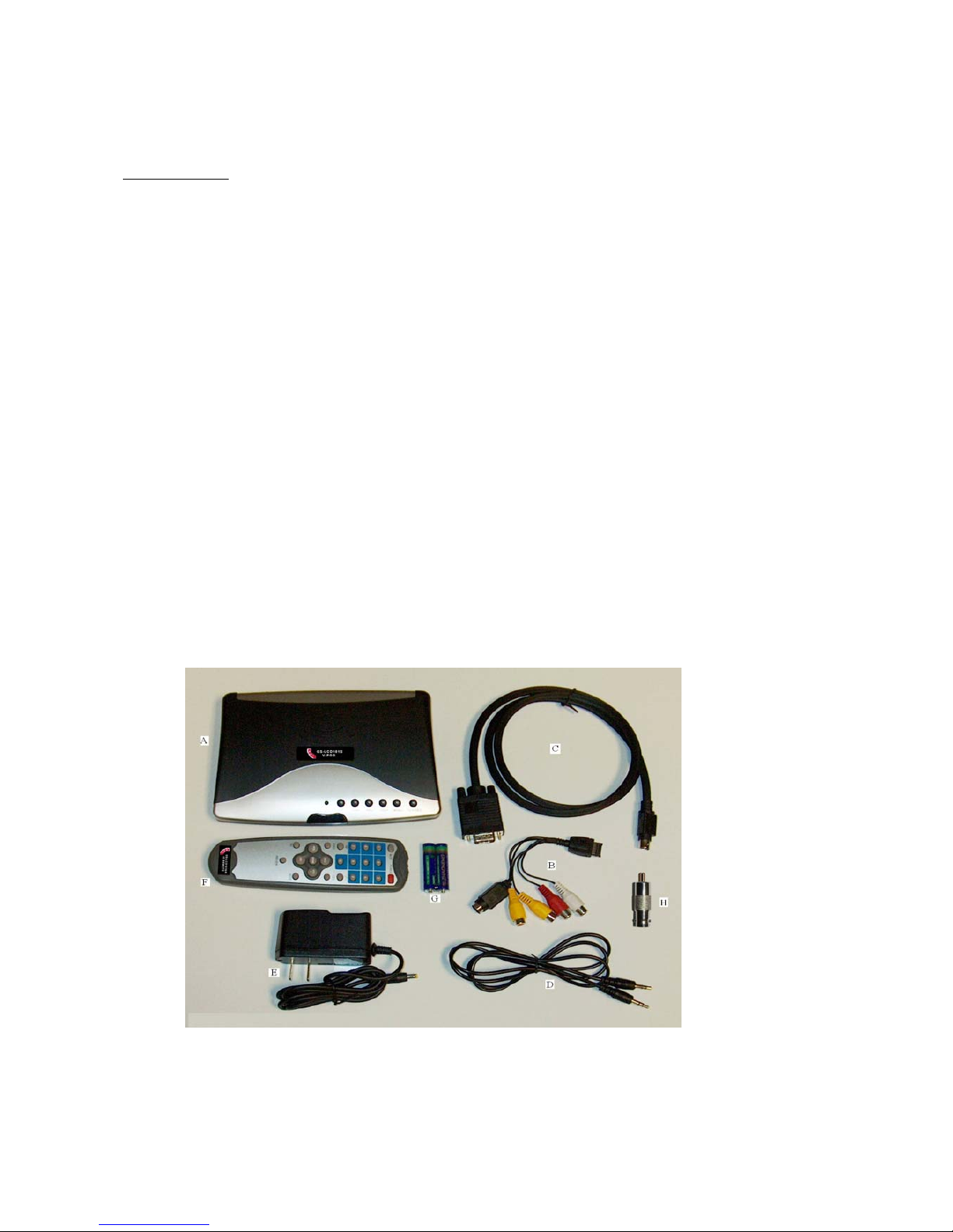
A. V-Pod: This is the main unit, and will need to be placed where the front controls
can be accessed and/or in visual range of the IR Remote Control.
B. MMI INPUT ADAPTOR CABLE: Used to connect various singal inputs to the V-Pod
1. Yellow RCA-F, (Camera) 75ohm Composite Video
2. Yellow RCA-F, (DVD) Line Level Composite Video
3. Black S-Video, S-Video connector
4. Red RCA-F, Audio - Right Channel
5. White RCA-F, Audio - Left Channel
C. VGA input cord: Used to connect a Computer VGA (Monitor) output to the V-POD VGA Input
D. Audio Patch Cable: Used to connect an external (Stereo) audio source to the V-Pod Audio
Input jack (or) V-Pod (Stereo) audio output jack to another audio device such as the speakers
on the GSI-Impressions LCD Monitor.
E. Power Supply: This is the 5VDC power supply that powers the V-Pod.
F. Remote Control: For remote operation of your V-Pod.
G. Batteries: 2 x AAA Alkaline Batteries (for your remote)
H. RCA male & BNC female connector.
Pg. 1 IM121906
The V-Pod is a CCTV composite video translator which with video resolution allows you to use your
LCD monitor with a composite video input. The V-Pod provides you with a low cost TFT alternative for
security video and the ability to select computer, TV and video.
Thank you for purchasing the GS-LCD101S, or also known as the “V-Pod” with video,
composite video, resolution and color enhancement.
Page 3
II
2. Line Level (Yellow)
3. S-Video (Black)
4. Audio - Right (Red)
5. Audio - Left (White)
1. Video (Yellow)
Pg. 2 IM121906
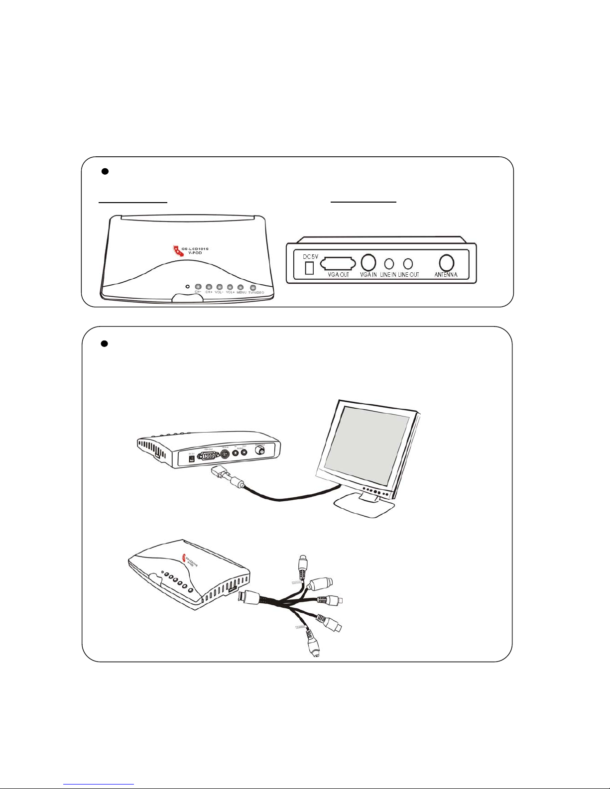
Getting familiar with GS-LCD101S
Front Panel Rear Panel
Connecting GS-LCD101S
S
tep 1
Connecting the GS-LCD101S and LCD with VGA
S
tep 2
Connecting the MMI cable with MMI interface.
Page 4

Pg. 3 IM121906
S
tep 4
Connectin
g
the power Supply (DC5V).
S
tep 5
Press the TV/VIDEO button for five seconde when the product
is powered on.
GS-LCD101S
MMI CABLE
CAMER
A
RCA & BNC PLUG
DVR/Multi
plex
Monito
r
Video
S
tep 3
Connecting the camera jack of RCA/S cable to DVR/
multiplexer with RCA male & BNC female plug.
Page 5

III. Setting up your V-Pod
1. Connect the “MMI Cable” (#B on the picture) to the side of the V-Pod, and
then insert the BNC-RCA adaptor onto the Yellow "Camera" Connector.
Red= Audio Right, White = Audio Left, Black = S-Video, Yellow = DVD Player, Yellow = Video Line Level
2. Connect the Audio Patch Cable (#D on the picture) to “Audio Out” on the back of the
V-Pod, and then connect the other end to the “Audio In” port on the back of the monitor.
3. Connect the Power Supply (#E on the picture) to “DC 5V” on the back of the V-Pod.
4. Connect the Monitor’s VGA cable to the “VGA-Out” Port on the back of the V-Pod.
5. Connect an antenna signal to the “Antenna” port on the back of the V-Pod. (Optional,
but needed for TV mode of the V-Pod)
6. Place both of the batteries (Item G) in the remote as indicated by the remote cover.
III.
Operation of the V-Pod
1. TV/VIDEO: This button allows you to switch which input mode you are going to be viewing
2. Menu: This will bring up the “On-Screen Menu” so you can make adjustments to the settings.
3. Vol +/- These buttons allow standard volume control over the volume level.
* NOTE: To turn the unit on or off, hold down the TV/Video button for five seconds.
If there is no video signal detected the unit will shut off on it's own after a few minutes.
Pg. 4 IM121906
Page 6

IV. Menu Options
BRIGHTNESS 50
CONTRAST 50
SATURATION 50
HUE 50
SHARPNESS 50
VOLUME 50
BALANCE 50
CHR ENH ON/OFF
LUMA STR OFF/ON
MOVIE OFF/ON
BLK EX ON/OFF
NOISE RE MID/HIGH/OFF/LOW
CHLNUM 001
CHL EDIT /CUR CHL/CHLSKIP/CHLSWH/EXCH ENTER
CHL MICR 74.05 MHZ
MUNUAL SRH
AUTO SRH
C.SYS AUTO/PAL/NTSC
ROUTE TV/ VIDEO/S-VIDEO
BACKGRD ON/OFF
MODE SVGA75/XGA60/XGA75/VGA60/VGA75/SVGA60
PIPS 4/9/16
POPP LEFT 1/RIGHT 1/CHNTER/LEFT 2/RIGHT 2
DEFAULT
LANGUAGE ENGLISH/ CHINESE
H POSITION 035
V POSITION 031
AUTO OFF CLOSE/OPEN
IMPACT CLOSE/FADE/BLEND
STYLE COOL/FASH/SIMP/CLAS
Pg. 5 IM121906
Picsndsmd Picenh Tune Confi
g
OSD
Picsnd Picenh Tune Confi
g
OSD
Picsnd Picenh Tune Confi
g
OSD
Picsnd Picenh Tune Confi
g
OSD
Picsnd Picenh Tune Confi
g
OSD
Page 7

V. Menu Descriptions
Brightness: Brightness is how you adjst the intensity of the picture you are viewing on your monitor.
High = Brighter, Low = Darker
Contrast: Contrast is also related to intensity of the picture you are viewing on your monitor.
High = Shiny, Low = Dull
Saturation: Saturation is the setting which adjusts how much of the color signal is shown.
High = Intense color, Low = Black & White
Hue: Hue is the adjustment for Red, Green & Blue. Blue is constant with a mix of red and green.
Low = More Green & Less Red, High = Less Green & More Red
Sharpness: Sharpness is the adjustment for how crisp or smooth things appear.
Low = Smooth edges, High = Hard lines of objects
Volume: A measurment of your current volume settings
Low = Low Volume, High = High Volume
Mute: This is an on or off setting.
Balance: This is an audio setting for what has dominance in audio.
Low = Higher Left Side, Lower Right Side, High = Low Left Side & High Right Side
Program: Lists the channel you are currently adjusting
Band: The channel range you are set to view: VHF (2-13), VHFL, UHF
Skip: By using Channel +/- you will skip over this channel
Fine Tuning: For adjusting the tuning of that channel
*Note: If you tune too high or too low you will move to the next channel in line
Quick: For an "automated" scan through all channel settings
Auto: Whether the channel will adjust itself or keep to your adjustment to settings
Color System: This is to select what incoming video signal your unit will be proccessing
Choices: Auto, Pal (European/Asian), NTSC (USA), P 60, SECAM
Sound System: This is showing the setting which cannot be changed: DK I BG M
Blue Screen: This is a background screen that will come on when no signal can be detected
On or Off
Output Res: Adjustment fort what resolution and speed (MGHz) the V-Pod will use for the monitor.
Choices: 640x480/ 800x600/ 1024x768/ 1280x1024, all offered in 60MGHz and 75MGHz
Input Channel: This a display for which input you are currently viewing.
State Set: This menu item will revert all video settings to the detected "optimal" settings.
Language: This is what language you will view the on screen display in: English or Chinese
H Position: This is the measurment for where the On Screen Display (OSD) will appear.
V Position: This is the other measurment for where the OSD will appear.
Back Color: This is where you can select which color you want the OSD Menu Box to be. 0 - 7
Blend Switch: Not used; leave in "off" position
Transparancy: This is how solid or see through your OSD is: 0 - 3
OSD Time: This is a timer for how many seconds of no activity it will close the OSD on it's own
OFF/ 5 sec/ 10 sec/ 20 sec
Pg. 6 IM121906
Page 8

TUNER SETUP
When in the tuner mode (selected by pushing the TV/VIDEO button) go into the menu and move to
the TUNER tab.
1. Select QUICK TUNING to begin. This will go through your available channels and try and tune
them in to the units best ability. (What you will see is each channel be selected and the tuner
be calibrated by itself to get the best picture possible for that channel. Similar to the auto-configure
mode you might see on a newer television.)
2. Exit Menu
3. Select a channel you want to adjust and then go back into the Menu/Tuner section.
4. Fine Tuning will allow you to adjust the frequency the V-Pod is set on. Note: If the channel you
are adjusting goes to high it will start moving up in stations. IE: If you are tuning channel 4 and keep
adjusting it higher and higher, you will soon start seeing channel 5 instead, then 6 etc. Or if you went
too far down you would be on channel 3, then 2 etc…
Pg. 7 IM121906
 Loading...