

Page 1
™
GSI CORTI
USER MANUAL
Setting The Clinical Standard www.grason-stadler.com
Grason-Stadler, 10395 West 70th Street, Eden Prairie, Minnesota 55344
800-700-2282 • 952-278-4402 • fax 952-278-4401 • e-mail info@grason-stadler.com
Part Number D-0103241 Rev D
Page 2
EC REP
Title: GSI Corti™ OAE Instrument
Grason-Stadler (GSI)
10395 West 70th Street, Eden Prairie, MN 55344, USA
Copyright © 2013 Grason-Stadler. All rights reserved. No part of this publication may be reproduced or
transmitted in any form or by any means without the prior written permission of GSI. The information in
this publication is proprietary to GSI.
Compliance
The CE 0344 mark identifies compliance with the Medical Device Directive 93/42/EEC. GrasonStadler is an ISO 13485 certified corporation.
0344
Page 3

Table of Contents
Standards Compliance ............................................................................................................................................ 1
Indications for Use .................................................................................................................................................. 2
Warranty .................................................................................................................................................................... 3
Warnings, Cautions, and Errors ........................................................................................................................... 4
Status/Error Messages ............................................................................................................................................... 6
Customer Responsibility ......................................................................................................................................... 8
Safety Precautions .................................................................................................................................................... 9
Cautions - General ..................................................................................................................................................... 9
Warning - Electric Shock Hazards .......................................................................................................................... 10
Warning - In Case of Emergency ............................................................................................................................ 10
Warning - Explosion ............................................................................................................................................... 10
Warning - Battery Safety ......................................................................................................................................... 10
Warning - General ................................................................................................................................................... 10
Recycling/Disposal .................................................................................................................................................. 11
Regulatory Symbols ............................................................................................................................................... 12
Introduction ............................................................................................................................................................. 13
How Does the Corti Device Work? ......................................................................................................................... 14
What are DPOAEs? ................................................................................................................................................. 14
What Are TEOAEs? ................................................................................................................................................ 15
What Do Otoacoustic Emission Results Tell Us? ................................................................................................... 15
What Frequency Range of Hearing is Estimated? ................................................................................................... 15
How are the Results Stored and Reported? ............................................................................................................. 15
Sensitivity and Specificity ....................................................................................................................................... 16
Setup .......................................................................................................................................................................... 17
Unpacking the System ............................................................................................................................................. 17
Optional Accessories ............................................................................................................................................... 17
Cradle (Optional) .................................................................................................................................................... 17
Battery Charging ..................................................................................................................................................... 17
Installing the Probe ................................................................................................................................................. 18
Attaching Probe Tube.............................................................................................................................................. 19
Attaching Eartips ..................................................................................................................................................... 19
Operating Instructions .......................................................................................................................................... 21
Preparing the Patient for Testing ............................................................................................................................. 21
i
Page 4

Turning On the Instrument ...................................................................................................................................... 21
Control Panel ........................................................................................................................................................... 21
Main Menu .............................................................................................................................................................. 22
Selecting the Test Protocol ...................................................................................................................................... 22
Starting a Test ......................................................................................................................................................... 22
AutoStart Probe Check ................................................................................................................................ ............ 23
Test Phase ............................................................................................................................................................... 23
SNR Bar Graph View .............................................................................................................................................. 24
Value Graph View ................................................................................................................................................... 24
Viewing Results ...................................................................................................................................................... 24
Test Technique ........................................................................................................................................................ 25
Noise Sources .......................................................................................................................................................... 26
Turning Off the Instrument ..................................................................................................................................... 26
Managing Results ................................................................................................................................................... 27
Saving Results ......................................................................................................................................................... 27
Deleting Results ...................................................................................................................................................... 28
Printing to a Thermal Printer ................................................................................................................................... 28
Connecting to the Corti Data Manager .................................................................................................................... 29
Understanding Printed Results ........................................................................................................................... 30
Understanding the DPOAE Printout ....................................................................................................................... 30
Understanding the TEOAE Printout ........................................................................................................................ 30
Rounding Results .................................................................................................................................................... 31
Clock Settings .......................................................................................................................................................... 32
Accessing the Clock Menu ...................................................................................................................................... 32
Changing the Date/Time ......................................................................................................................................... 32
Instrument Settings ................................................................................................................................................ 33
Wireless Device Pairing .......................................................................................................................................... 33
Clearing Test Results .............................................................................................................................................. 34
Auto Shutdown Time .............................................................................................................................................. 34
Save Mode/Storing Test Results ............................................................................................................................. 34
Minimum Amplitude ............................................................................................................................................... 35
Clock Mode ................................................................................................ ............................................................. 35
Graph Style.............................................................................................................................................................. 35
Language ................................................................................................................................................................. 36
Reset to Default ....................................................................................................................................................... 36
ii
Page 5

Advanced Options for the DPOAE Diagnostic Unit ...................................................................................... 37
Instructions for Customizing a Test Protocol .......................................................................................................... 37
Selecting the Level of Primary Tones ..................................................................................................................... 38
Setting the Averaging Time .................................................................................................................................... 38
Setting the PASS SNR Level .................................................................................................................................. 38
Setting the Number of Frequencies for PASS ......................................................................................................... 39
Reset Protocol ......................................................................................................................................................... 39
Save Protocol .......................................................................................................................................................... 39
Advanced Options for the TEOAE Diagnostic Unit ...................................................................................... 40
Instructions for Customizing a Test Protocol .......................................................................................................... 40
Selecting the Averaging Time ................................................................................................................................. 41
Setting the PASS SNR Level .................................................................................................................................. 41
Setting the Number of Frequencies for PASS ......................................................................................................... 41
Reset Protocol ......................................................................................................................................................... 42
Save Protocol .......................................................................................................................................................... 42
Cleaning and Maintenance ................................................................................................................................... 43
Cleaning and Disinfection ....................................................................................................................................... 43
Maintenance ............................................................................................................................................................ 44
Probe tube Replacement ................................ ................................ ................................................................ .......... 44
Troubleshooting ...................................................................................................................................................... 45
Appendix A: Specifications .................................................................................................................................. 47
Appendix B: Flowcharts ................................ ................................................................................................ ....... 48
Flowchart - Measurement ........................................................................................................................................ 48
Flowchart – Setup Menus ........................................................................................................................................ 49
Appendix C: Test Sequence ................................................................................................................................. 50
FOR DPOAE ........................................................................................................................................................... 50
FOR TEOAE ........................................................................................................................................................... 50
Comment about Variations in the SNR Estimate .................................................................................................... 51
Appendix D: Pass/Refer Criteria ........................................................................................................................ 52
Pass/Refer Criteria for DPOAE ............................................................................................................................... 52
Pass/Refer Criteria for TEOAE ............................................................................................................................... 53
Appendix E: Configurations and Test Protocols ............................................................................................ 54
Appendix F: EMC Compatibility ....................................................................................................................... 56
Electromagnetic Compatibility................................................................................................................................ 56
Electrical Safety, EMC and Associated Standards .................................................................................................. 56
Guidance and Manufacturer’s Declaration - Electromagnetic Emissions ............................................................... 57
iii
Page 6
Recommended Separation Distances between Portable and Mobile RF Communications Equipment and the GSI
Corti ........................................................................................................................................................................ 57
Guidance and Manufacturer’s Declaration - Electromagnetic Immunity ................................................................ 58
Guidance and Manufacturer’s Declaration - Electromagnetic Immunity ................................................................ 59
iv
Page 7
Standards Compliance
Standard
Issue
Date
Title
ANSI/ASA 3.6
2010
Specification for Audiometers
IEC 60601-1
2005
Medical Electrical Equipment – General Requirements for Basic
Safety and Essential Performance, Ed. 3
IEC 60645-1
2004
Electroacoustics - Audiological equipment -- Part 1: Pure-tone
audiometers
IEC 60645-3
2007
Electroacoustics - Audiometric equipment -- Part 3: Test signals of
short duration
IEC 60645-6
2010
Electroacoustics – Audiometric Equipment – Part 6: Instruments for
the measurement of otoacoustic emissions
ISO 14971
2007
Application of Risk Management to Medical Devices
ISO 10993
2009
Biological Evaluation of Medical Devices
EN 60601-1-2
2007
Medical electrical equipment -- Part 1-2: General requirements for
basic safety and essential performance - Collateral standard:
Electromagnetic compatibility - Requirements and Tests.
FCC Part 15
FCC 47CFR, Part 15.247 & 15.249 (Wireless)
IEC 60601-1
2005
Clause 8.9.1.8; Pollution Degree Classification: 2
Page 8
Indications For Use
Intended Use: The GSI Corti is a test instrument that measures otoacoustic
emissions in infants, children, and adults.
Indications for Use: The GSI Corti series is indicated for testing of
cochlear function in infants, children and adults by measuring otoacoustic
emissions (OAEs). The OAEs are generated by a series of clicks that are
directed into the ear canal.
Otoacoustic emissions are low level audio-frequency sounds that are
produced by the cochlea as part of the normal-hearing process. Available
evidence suggests that otoacoustic emissions are generated by the cochlea’s
outer hair cells and that the presence of OAEs is an indication that the outer
hair cells are viable. Clinical evidence indicates that these emissions
normally occur with normal hearing, or at most, mild hearing loss (usually
30-40 dB HL). The majority of hearing-impaired individuals will be
identified by a simple OAE test.
Page 9
Warranty
We, Grason-Stadler, warrant that this product is free from defects in material
and workmanship and, when properly installed and used, will perform in
accordance with applicable specifications. If within one year after original
shipment, it is found not to meet this standard; it will be repaired, or at our
option, replaced at no charge except for transportation costs, when returned
to an authorized Grason-Stadler facility. If field service is requested, there
will be no charge for labor or material; however, there will be a charge for
travel expense at the service center’s current rate.
NOTE: Changes in the product not approved in writing by Grason-Stadler
shall void this warranty. Grason-Stadler shall not be responsible for any
indirect, special or consequential damages, even if notice has been given in
advance of the possibility of such damages.
THIS WARRANTY IS IN LIEU OF ALL OTHER WARRANTIES,
EXPRESSED OR IMPLIED, INCLUDING BUT NOT LIMITED TO, ANY
IMPLIED WARRANTY OF MERCHANTABILITY OR FITNESS FOR A
PARTICULAR PURPOSE.
Page 10
Warnings, Cautions, and Errors
The WARNING label identifies conditions or practices
that may present danger to the patient and/or user.
The CAUTION label identifies conditions or practices
that could result in damage to the equipment
The Corti Otoacoustic Emission Test System should be
charged using only the provided power supply. Injury to
personnel or damage to equipment can result when a
three-prong to two-prong adaptor is connected between
the Corti power supply and an AC outlet.
No modifications of the equipment are allowed by anyone
other than a qualified GSI representative. Modification
of the equipment could be hazardous.
The Corti product has been verified by an independent
laboratory to conform to international standards for EMC
(electromagnetic emissions and immunity). The user is
advised to avoid installation and use of this instrument in
proximity with other devices or equipment that may emit
or be susceptible to electromagnetic interference,
including mobile phones. If the instrument is used
adjacent to other devices or equipment, the user is
instructed to verify that no disturbance is found in the
operation of this or other equipment in proximity.
This icon indicates that patient applied parts of the
instrument conform to IEC 60601-1:2005, Type B
requirements.
WARNING
CAUTION
WARNING
In this manual the following two labels identify potentially dangerous or
destructive conditions and procedures.
NOTE: Notes help you identify areas of possible confusion and avoid
potential problems during system operation.
Page 11
Instruments which bear the Underwriters Laboratories, Inc.
label should be interconnected with accessories that have the
proper electrical compatibility and are listed as meeting the
requirements of the UL Medical and Dental Equipment
Standard. Connection of accessories not meeting these
requirements may result in electrical leakage currents in
excess of those allowed by the standard and present a potential
electrical shock hazard to the person being tested.
Any program aimed at obtaining reliable measurements
of otoacoustic emissions should be staffed and supervised
by appropriately-trained individuals.
Page 12
Status/Error Messages
Attach Probe
No probe is detected at the start of a test.
Device not
Responding
The printer is not responding to queries from the instrument.
BT Device Not
Found
The paired wireless device cannot be detected. The device may be
turned off or too far away.
BT Error #xxx
There is an error condition with the wireless device. Check the
status.
BT Not
Configured
The Corti instrument is not paired with any wireless device.
Fit Error
Cannot Obtain P
For a DP test, the desired level (L1 or L2) cannot be obtained within
allowable limits. User should refit the probe and retry the test.
Fit Error
Too High
For a DP test, the level of the calibration tone is too high. User
should refit the probe and retry the test.
Fit Error
Too Low
For a DP test, the level of the calibration tone is too low. User
should refit the probe and retry the test.
Limit Error
Overflow error during the calculation of the DFTs for a DP test.
User should repeat the test.
Memory Almost
Full
Saved tests are within 5 tests of the maximum limit.
Memory Full!
The maximum saved test limit is reached. The user will need to clear
the memory before any additional tests can be performed.
Power Low!
The battery charge level is too low for operation. The user must
charge the battery before additional tests can be performed.
Printer Error
Indicates a problem with the printer. Check the printer status.
Printer Paper Out!
Indicates printer paper has run out.
Time/Date Error
The clock is checked during power on to ensure it has not lost time
and been reset. In the case of clock reset, this message is shown. The
user should set the correct date/time.
Due for Service
Daily reminder will appear when the calibration due date has passed.
NOISE / Orange
The indicator labeled ‘NOISE’ provides a visual indication (AMBER)
that the noise level measured during the test exceeds a nominal
threshold.
Also used to indicate some error conditions and when the outcome of
test is REFER, NOISY, or NO SEAL.
TEST / Yellow
The indicator labeled ‘TEST’ provides a visual indication (YELLOW)
that the selected test is being performed. This indicator will remain on
steady state during the test function.
READY / Green
The indicator labeled ‘READY’ lets the user know that the instrument
is not currently performing a test function and that it is available to
perform a test function.
CHARGE / Blue
The indicator labeled ‘CHARGE’ provides a visual indication
(BLUE) of the battery recharging function and battery status. The rate
Display Messages:
Indicator LEDs (lights):
Page 13
of illumination of the indicator provides a means of identifying the
status of the charging function.
Page 14
Customer Responsibility
This product and its components will perform reliably only when
operated and maintained in accordance with the instructions
contained in this manual, accompanying labels, and/or inserts. A
defective product should not be used. Make sure all connections to
external accessories are snug and secured properly. Parts which
may be broken or missing or are visibly worn, distorted, or
contaminated should be replaced immediately with clean, genuine
replacement parts manufactured by or available from GSI.
This product should not be used in the presence of fluid that can
come into contact with any of the electronic components or wiring.
Should the user suspect fluids have contacted the system
components or accessories, the unit should not be used until
deemed safe by a GSI certified service technician.
Do NOT use in the presence of flammable gaseous mixtures. Users
should consider the possibility of explosions or fire when using this
device in close proximity to flammable anesthetic gases.
Do NOT use the Corti in a highly oxygen-enriched environment,
such as a hyperbaric chamber, oxygen tent, etc.
Equipment is not user repairable. Repairs and battery replacement
must be performed by a qualified service representative only.
This device complies with part 15 of the FCC Rules. Operation is
subject to the condition that this device does not cause harmful
interference.
Use and store the instrument indoors only. It is recommended that
the instrument be operated within an ambient temperature range of
15°C / 59°F to 35°C / 95°F and in relative humidity between 30%
and 90% (non-condensing).
Transport and store the instrument in temperature between +5°C to
40°C.
Annual calibration recommended. Have an authorized service
technician perform electrical safety checks on the unit in order to
maintain continued compliance to IEC and UL 60601-1.
WARNING
Page 15
Safety Precautions
If the system is not functioning properly, do not operate it until all
necessary repairs are made and the unit is tested and calibrated for
proper functioning in accordance with GSI published specifications.
Use only the disposable eartips designed for use with this instrument.
Never insert the probe tube into the ear canal without affixing an
eartip.
The eartips are disposable and for single patient use only. Do not clean
or reuse eartips.
Do not drop or otherwise cause undue impact to this device. If the
instrument is dropped or otherwise damaged, return it to the
manufacturer for repair and/or calibration. Do not use the instrument
if any damage is suspected.
US federal law restricts this device to sale by or on the order of
a physician or licensed hearing care professional.
CAUTION
The following safety precautions must be observed at all times. General
safety precautions must be followed when operating electrical
equipment. Failure to observe these precautions could result in damage
to the equipment and injury to the operator or patient.
The employer should instruct each employee in the recognition and
avoidance of unsafe conditions and the regulations applicable to his or
her work environment to control or eliminate any hazards or other
exposure to illness or injury.
It is understood that safety rules within individual organizations vary.
If a conflict exists between the material contained in this manual and
the rules of the organization using this instrument, the more stringent
rules should take precedence.
The Corti is intended to be used by hearing healthcare professionals
(i.e. ENT doctors, audiologists) and/or technicians, neonatal nurses and
school nurses who have been trained by a hearing healthcare
professional.
Cautions - General
Page 16
Warning - Electric Shock Hazards
WARNING
WARNING
WARNING
Do not open the case of the Corti Instrument. Refer servicing to
qualified personnel.
Do not touch the contacts on the bottom of the instrument and the
patient at the same time.
Do not connect the instrument to the patient and
the PC at the same time.
Warning - In Case of Emergency
In case of emergency, disconnect the instrument
from the supply mains by removing the microUSB cable from the connector as shown in
Figure 2 on page 15.
Warning - Explosion
This system is not explosion proof. Do not use in the presence of
flammable anesthetics or other gases.
Warning - Battery Safety
Warning - General
This instrument contains a rechargeable lithiumion battery. The battery is not user replaceable
and must be returned to an authorized GSI
service location for repair.
Proper use of this device depends on careful
reading of all instructions.
Page 17
Recycling/Disposal
WARNING
Many local laws and regulations require special procedures to recycle or
dispose of electrical equipment-related waste including batteries, printed
circuit boards, electronic components, wiring and other elements of electronic
devices. Follow all your respective local laws and regulations for the proper
disposal of batteries and any other parts of this system.
Below is the contact address for proper return or disposal of electronic wastes
relating to GSI products in Europe and other localities.
Grason-Stadler (GSI)
10395 West 70th Street, Eden Prairie, MN 55344, USA
Batteries may explode or cause burns, if disassembled, crushed or exposed to
fire or high temperatures.
Page 18
Regulatory Symbols
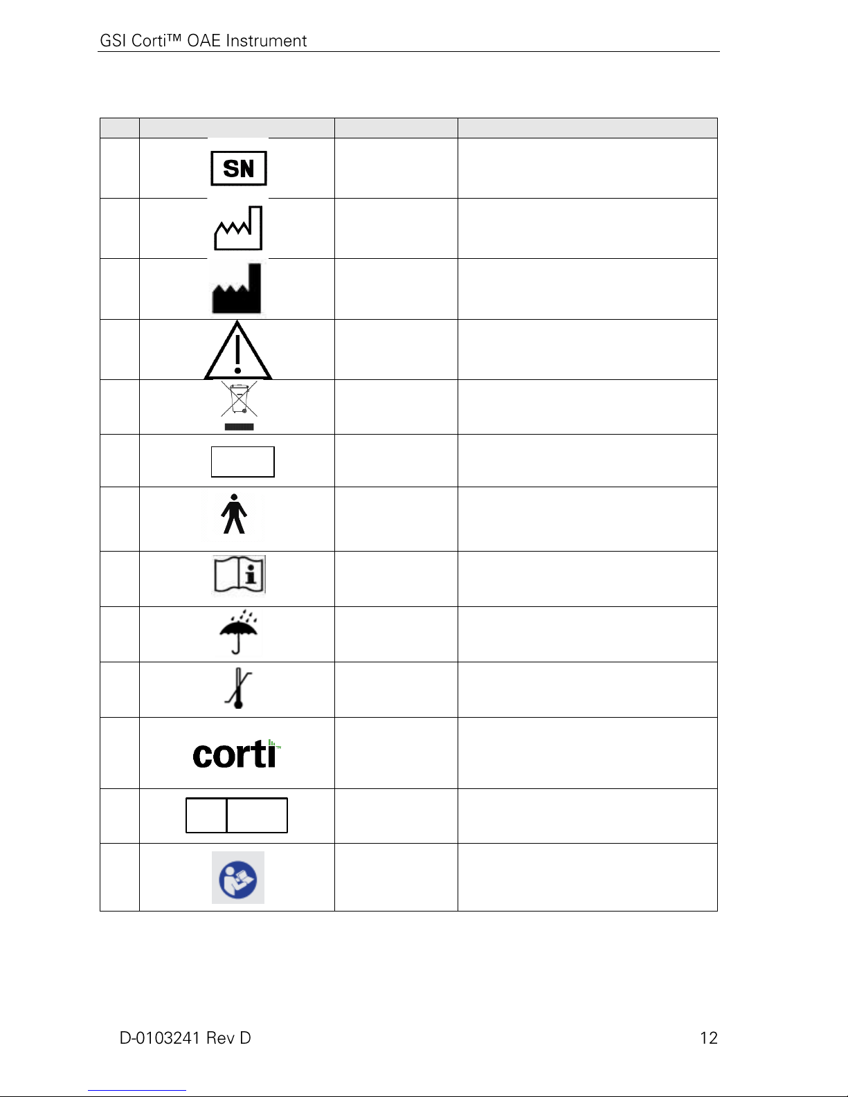
No.
Symbol
IEC Pub.
Description
980 & 60601-1
Serial Number
980 & 60601-1
Date of Manufacture
980 & 60601-1
Manufacturer
980 & 60601-1
Caution, Consult Accompanying
Documents
980 & 60601-1
Return to Authorized Representative,
Special Disposal Required
980 & 60601-1
Reference Number
60601-1
B Patient Applied Part According to
IEC60601-1
980 & 60601-1
Consult Operating Instructions
60601-1
Keep Dry
60601-1
Transport and Storage Temperature
range
Logo
EC REP
980 & 60601-1
EU Authorized Representative
ISO 7010-
M002&60601-
1
Where Appropriate
REF
Page 19
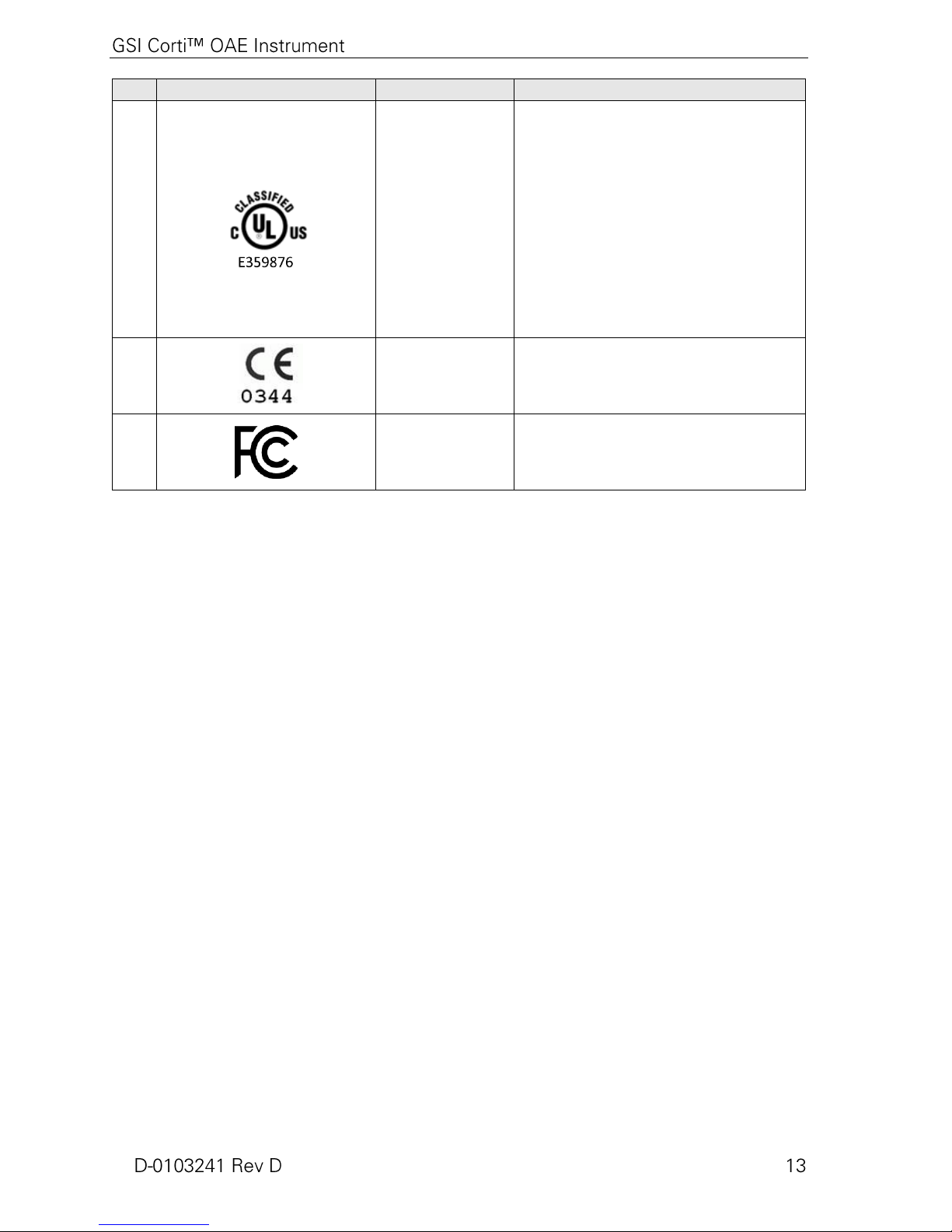
No.
Symbol
IEC Pub.
Description
CAN/CSA-
C22.2 No.
60601-1 (2008)
(Medical
Electrical
Equipment -
Part 1: General
Requirements
for Basic Safety
and Essential
Performance).
Only those products bearing the UL
Classification Mark for the U.S. and
Canada should be considered as being
covered by UL's Classification and
Follow-Up Service and meeting the
appropriate U.S. and Canadian
requirements.
980 & 60601-1
Conforms to European Medical
Device Directive 93/94/EEC
FCC part 15
FCC 47CFR, Part 15.247 & 15.249
(Wireless)
Page 20
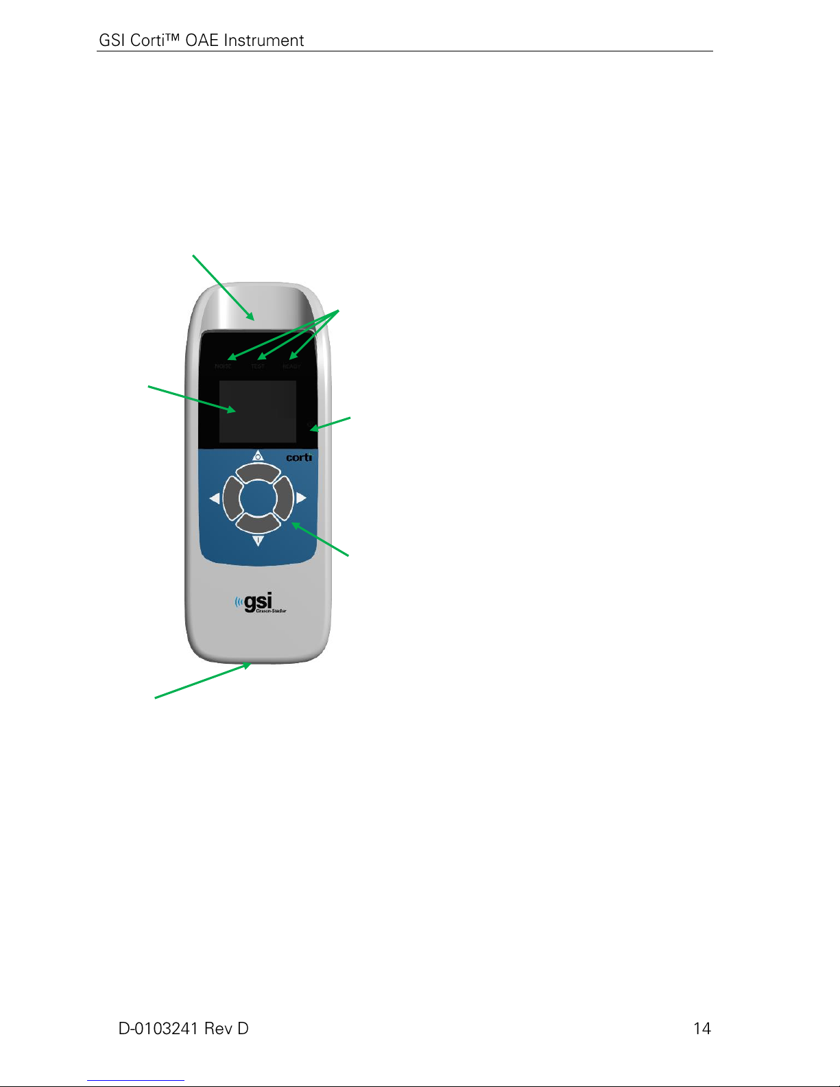
Introduction
User Interface
Buttons
Probe Connector
Micro-USB
Connector
Figure 1
Charge Status
Indicator
Display
Test Status
Indicators
The purpose of the Corti test system is to provide rapid measurement and
documentation of Distortion Product Otoacoustic Emissions (DPOAEs) or
Transient Evoked Otoacoustic Emissions (TEOAEs) at several frequencies.
How Does the Corti Device Work?
The system consists of the instrument,
probe, printer, single-use eartips
replaceable probe tubes and other
accessories. The Corti instrument
contains the hardware and software for
generating the test stimuli, measuring and
displaying the OAEs, and storing the
results until they are printed. The plastic
housing contains circuit boards that
provide the signal processing and display
the test results. The instrument also
contains a rechargeable lithium-ion
battery to power the device. The
instrument uses a liquid-crystal display
(LCD) and three light-emitting diodes
(LEDs) to provide a visual display of test
status to the operator. Four push buttons
located on the keypad of the device allow
the user to control testing and printing,
and to reset test protocols.
The Probe houses the speaker and
microphone which produce test stimuli
and measure the sound pressure level
(SPL) present in the sealed ear canal.
Interface of the instrument to the ear canal
is accomplished through disposable
eartips, which fit onto the probe tube. The
disposable eartips are color coded to
facilitate easy selection by size.
What are DPOAEs?
Distortion Product Otoacoustic Emissions (DPOAEs) are acoustic
signals that can be detected in the ear canal of a person with normal
outer hair cell function, subsequent to stimulation of the auditory
system with a pair of pure tones at frequencies f1 and f2. The resulting
emission of interest is the distortion product tone at the frequency
2f1-f2.
The Corti instrument generates a series of test tones, directs them into
the ear canal, and then measures the level of the DPOAE tone
generated by the cochlea. By using different test frequencies, the
Page 21

Corti device provides an estimate of outer hair cell function over a
wide range of frequencies.
What Are TEOAEs?
Transient Evoked Otoacoustic Emissions (TEOAEs) are acoustic
signals that can be detected in the ear canal of a person with normal
outer hair cell function, subsequent to stimulation of the auditory
system with a series of wideband clicks.
The Corti instrument generates a series of clicks, directs them into the
ear canal, and then analyzes the spectrum of the returning signal,
separating the noise and emission. By using band pass filters, the
Corti device provides an estimate of outer hair cell function over a
wide range of frequencies.
What Do Otoacoustic Emission Results Tell Us?
The presence of otoacoustic emissions suggests normal outer hair cell
function, which in turn correlates to normal hearing. However, a
passing result using this instrument is not an indication that the full
auditory system is normal. Thus, a PASS result should not be allowed
to override other indications that hearing is not normal. A full
audiologic evaluation should be administered if concerns about
hearing sensitivity persist. A REFER test result should not be
assumed to be an indicator of a lack of auditory function or the
presence of pathology; however, it should be followed with full
audiologic diagnostic testing and/or medical evaluation as
appropriate.
What Frequency Range of Hearing is Estimated?
DPOAEs: Approximately 1 kHz to 12 kHz (depending on the
frequency range selected). TEOAEs: Roughly 500 Hz to 4 kHz.
How are the Results Stored and Reported?
When the Corti is set in its default settings, the instrument will store
the results from one patient (left and right ear) in its non-volatile
memory for subsequent printing. However, the Corti instrument is
capable of storing up to 250 test results. The results are displayed via
the LCD on the front of the device and are stored in the device’s
internal memory. After testing is completed, results can be printed
using the printer and/or exported to a computer. Test results are stored
in the non-volatile memory so the operator can delay printing until a
later time if desired.
Page 22

Sensitivity and Specificity
Sensitivity and specificity of this type of device are based on the test
characteristics defined by the user, and may vary depending on
environmental and operating conditions. The presence of otoacoustic
emissions suggests normal outer hair cell function, which in turn
correlates to normal hearing. However, a passing result using this
instrument is not an indication that the full auditory system is normal.
Thus, a PASS result should not be allowed to override other
indications that hearing is not normal. A full audiologic evaluation
should be administered if concerns about hearing sensitivity persist.
A REFER test result should not be assumed to be an indicator of a
lack of auditory function; however, it should be followed with full
audiologic diagnostic testing.
Page 23

Setup
Figure 2
Unpacking the System
The following parts are shipped standard with each Corti system:
(1) Corti Unit (System Part Number 8103744)
(1) Corti Probe (Part Number 8103763)
(1) GSI Corti Software and Manuals CD (Part Number 8104215)
(1) GSI Corti Software and Manuals USB (Part Number 8104553)
(1) Single Use Eartip Kit (Part Number 8103765)
(1) Communications Cable, USB A/Micro-B (Part Number 8104249)
(1) Charging Cable, PSU 5V/Micro-B (Part Number 8029254)
(1) Corti Quick Guide (Part Number 8104290)
(1) Calibration Certificate (Part Number 8104432)
If any of these parts are missing, contact your special equipment
distributor or GSI. We recommend that you save the shipping box
and packing materials in case you need to store or ship the system.
Optional Accessories
The Corti optional accessories include a wireless thermal printer (Part
Number 8103161), cradle (Part Number 8103766) and carry case
(Part Number 8104052).
Cradle (Optional)
Battery Charging
The Corti unit can be placed in the optional cradle for charging the
Corti or connected to a PC via USB or wireless for communication to
the Corti Data Manager. Charging and connection to the PC can also
be conducted directly from the Corti unit. The remainder of this
manual assumes that charging and communication to the PC is direct
from the Corti unit, but note that either is possible.
The Corti instrument is powered by an integrated rechargeable
lithium-ion battery providing 15 hours of operation between full
charging. The battery status is indicated by the battery icon shown in
the upper right corner of the Main Menu (Display 1). Full battery
charge is represented by a full battery symbol on the display and
reduces to an empty battery in increments corresponding to the
discharge of the battery.
To charge the unit, connect the Micro-USB port on the bottom of the
instrument as shown in Figure 2, and connect the wall charger to the
mains outlet. To charge the Corti unit through the cradle, connect the
Micro-USB to the back of the cradle and the wall charger to the mains
outlet. Place the Corti unit firmly into the cradle.
NOTE: Misalignment of the plug and socket can cause damage. The
plug and socket should be visually inspected prior to each installation
of the charging cable. If damage is observed, contact GSI.
Page 24

The battery charge status indicator, located to the right of the display,
Figure 3
provides a visual indication (BLUE) of the battery recharging
function and battery status during operation.
During battery charging the indicator will be lit whenever the MicroUSB connector is engaged and powered. The rate of illumination of
the indicator provides a means of identifying the status of the
charging function, and is defined as follows:
Steady-state illumination indicates the battery is
fully charged. This identifies that the charging cycle
has been completed or was not implemented because
the battery was already fully charged.
Slow blink illumination indicates the charging
function is in process.
Fast blink illumination indicates a fault condition in
which the user would be directed by the user manual
to return the instrument for service.
During instrument operation, the user is warned of a low battery
condition by the following illumination of the battery status indicator:
Two fast blinks followed by a pause and then
repeated until the battery is charged.
Installing the Probe
Insert the Probe’s HDMI connector firmly into the socket on the top
of the Corti (Figure 3). The plug will fit in only one direction. The
GSI wave logo will align with the instrument control panel.
NOTE: Misalignment of the plug and socket can cause damage. The
plug and socket should be visually inspected prior to each installation
of the remote probe. If damage is observed, contact GSI.
Page 25

Figure 5
Figure 6
Figure 4
Figure 7
Attaching Probe Tube
Attaching Eartips
Probe Holder
A clear probe tube must be applied to the probe head before an eartip
is applied. Insert a new probe tube into the probe head until it is fully
seated (Figure 4). A properly inserted probe tube will snap securely
into place when it is fully seated in the probe head. It is not necessary
to replace the probe tube with each ear tip; the tube is reusable as long
as the probe tube is clear. To remove a probe tube, grasp the tube and
pull gently away from the probe head with a slight twist.
The Corti instrument comes with a box of disposable, single-use
eartips that fit a variety of ear canal sizes. The Corti probe must have
a probe tube applied (Figure 4) and an eartip attached (Figure 5)
before inserting it into an ear canal. The determination of the
appropriate eartip size should be made by persons with proper
training and experience. The eartip must seal the ear canal. The best
test results are obtained when the eartip is inserted deeply into the ear
canal instead of flush with the ear canal opening. Caution must be
taken, however, to ensure that the eartip does not extend too deeply
into the ear canal. Use only the eartips approved for use with the
instrument. The eartips are disposable and must be replaced after each
patient.
After selecting an eartip, push it onto the probe tube until it is flush
against the base of the probe tube (Figure 5). Twisting the eartip
slightly while pushing it onto the probe tube is recommended. Be sure
the eartip is fully seated on the probe. There should be no gaps
between the eartip and the collar of the probe head (Figure 6).
To remove the eartip, grasp the eartip gently at the base and twist it
while pulling it straight off the end of the probe tube.
NOTE: Grasping the base of the eartip will prevent the probe tube
from being inadvertently pulled out of the probe head along with the
eartip.
NOTE: If the probe tube becomes dirty or clogged, it must be
replaced. See the section Probe Tube Replacement on page 42 for
further information.
It is strongly recommended to place the probe into the probe holder
when the Corti is not in use. This should be done while the Corti is
placed on a counter top or table, or when the Corti unit is resting in
the Corti cradle. Placing the probe into the holder will help to protect
the probe head.
Make sure the probe holder is towards the end of the probe cable at
the GSI wave logo / HDMI connector end. Gently push the probe
Page 26

cable into the probe holder at the point of the probe head. Refer to
Figure 8
Figure 7 for an example of the probe in the probe holder when the
Corti is resting on a table. Refer to Figure 8 for example of the probe
in the probe holder when placed in a Corti cradle.
Page 27

Operating Instructions
Figure 9
Preparing the Patient for Testing
Otoscopic examination of the patient’s ear canals should be
performed prior to testing. Excessive cerumen or vernix in the ear
canals may interfere with the test and give invalid or incomplete
results. Patients with excessive cerumen, debris, or foreign bodies in
the ear canals should be referred to an audiologist or physician for
removal of the blockage prior to testing.
Place the patient in a position that will allow easy access to the ear
canal. The patient should remain still and quiet while the test is being
performed.
Turning On the Instrument
To turn on the Corti instrument, press the DOWN button located
below the instrument’s display screen (Figure 9). The yellow TEST
light will appear briefly just above the display. The green READY
light will remain on indicating the instrument is ready for use. A Flash
Screen will appear briefly, indicating the software version, serial
number, next calibration date, and type of instrument:
SCR Screener with TE or DP
SC+ Screener with TE and DP
STD Diagnostic TE or DP
CMB Diagnostic TE and DP
Control Panel
The Corti instrument uses 4 buttons to control all functions of the
instrument (Figure 9). These buttons are arranged in a directional
cursor format. The arrows on the keypad (LEFT, RIGHT, UP,
and DOWN) correspond to the arrows that are used on the screen.
The screen will indicate which button to push by showing the
appropriate arrow.
NOTE: The UP key will always bring the instrument back to either
the previous menu or the main menu. The UP key will also access the
print command from the Main Menu.
Page 28

Main Menu
Display 1
Battery Status
Date & Time
Selected Protocol
Start Right
Start Left
Ear Test
Change Protocol
and Settings
Number of Stored
Tests
Display 2
Display 3
Selecting the Test Protocol
The currently selected protocol is shown on the Main Menu (Display
1). To change the selected protocol press CHANGE at the Main
Menu. The Change Protocol display will appear (Display 2). Use the
CHANGE arrow buttons to change the selected protocol. Press
the up arrow to return to the Main Menu to begin testing. Press the
SETUP to enter the setup menus.
For Diagnostic DPOAE or TEOAE units, there is one default test
protocol and a number of user definable protocols. For Screener
DPOAE or TEOAE units there are 2 fixed protocols. Appendix E
contains complete information on protocol settings. Instructions for
customizing protocols on the Diagnostic units can be found in the
sections Advanced Options for DPOAE Diagnostic Unit on page 35
or Advanced Options for TEOAE Diagnostic Unit on page 38.
NOTE: The default protocols: DP 4s, DP 2s, TE 64s and TE 32s
cannot be customized.
Ear Test
Starting a Test
To obtain a seal and measure emissions, gently insert the eartip into
the patient’s ear canal. It should fit snugly and comfortably. The best
test results are obtained when an eartip is inserted deeply into the ear
canal instead of flush with the ear canal.
To begin a test, insert the probe into the ear and select either the
LEFT or RIGHT arrow key to indicate which ear will be tested.
Page 29

AutoStart Probe Check
Display 7
Display 4
Display 5
Display 6
After the test ear is selected, the AutoStart Probe Check will begin
automatically. The Probe Check display shows a cone, larger at the
left and tapering toward the right, representing the ear canal volume
from very large (blue area) to very small (orange area).
The vertical white bar indicates the measured ear canal volume and
probe fit stability:
Appropriate adjustments of the eartip position and size selection
should be made until the white indicator falls within the green area
and remains stable.
If the test will not progress past the Probe Check phase, change the
probe tube, check that the probe connector is fully seated in the
socket, and try again.
NOTE: To test children with PE tubes, the Probe Check needs to be
disabled. This is accomplished by first inserting the probe with
appropriate ear tip into the ear canal and obtaining a proper seal. To
disable AutoStart at the main menu select the ear to be tested by
holding down the RIGHT or LEFT arrow keys for 3 seconds until the
green “ready” light turns off. Once the key is released, the Corti will
calibrate and test as before. The appropriate in-the-ear stimulus
intensity levels are applied to ears with PE tubes.
Blue (Display 4) = The ear canal volume is too large for the
test to begin. The probe is not in the ear or there is a large
leak.
Gray (Display 5) = Ear seal indicator will remain gray until
a seal is obtained.
Green (Display 56) = The ear canal volume is in the target
range for testing. The test will begin automatically if the
probe fit is stable.
Orange (Display 7) = The ear canal volume is too small for
the test begin. The eartip may be pressed against the ear
canal wall or the probe tube may be completely clogged.
Test Phase
The Corti instrument will automatically perform a calibration at the
start of each test. During calibration a series of tones will be
presented to the ear canal to calibrate the levels of the frequencies to
be tested. Following calibration of the test tones, the test phase will
begin automatically.
The display on the Corti test instrument will indicate the results of the
test with a graphic display. The display will be generated and shown
during the test and can be reviewed after the test is complete.
The Corti allows the user to select from two options for viewing the
results. The SNR graph view shows the signal-to-ratio for each DP
Page 30

SNR Bar Graph View
Display 8
Display 11
Display 12
Display 9
Display 10
Value Graph View
test frequency or TE test band. The Value graph view shows the
absolute emission and noise levels for each DP test frequency or TE
test band.
Display 8 shows the SNR bar graph view. These are the signal-tonoise ratio (SNR) test results which are displayed as the emissions
and noise floor are measured. Each column represents one DP test
frequency or TE frequency band. The height of each column
represents the SNR measured.
When a protocol with a Pass criteria has been selected, the user will
see a horizontal green line at the decibel level corresponding to the
SNR required for a PASS. Green bars are a pass, yellow a non-Pass.
Display 9 shows the Value graph view for left ear test. Dark blue “x”
symbols represent the absolute emission levels at each DP test
frequency or TE frequency band. Light blue upside-down triangles
represent the noise floor at each DP test frequency or TE frequency
band.
Display 10 shows the Value graph view for a right ear test. Red circle
symbols represent the absolute emission levels at each DP test
frequency or TE frequency band. The shaded area is the Expanded
Boys Town Norms template. See page 23 for a description of the
template.
Refer to pages 33 and 34 for instructions to switch the default setting
of the graphs and for turning on the normative template.
NOTE: The up arrow key can be used to abort a test in progress.
No record of an aborted test will be saved in memory.
Viewing Results
When testing is complete, the green “READY” light is illuminated
and a display similar to Display 11 or Display 2 will appear. The
results of the test are automatically saved in memory as soon as the
test is complete. The results will be saved even if the instrument is
turned off or the battery is temporarily depleted. This screen indicates
the test ear and further gives the results of the test.
“PASS” on the screen indicates the patient passed screening
“REFER” indicates the patient did not pass screening
“NOISY” indicates excessive noise was present during the test
“NO SEAL” indicates a seal was not maintained throughout the
test
“FIT ERR” indicates inadequate probe placement in the ear canal
to produce target stimulus intensities
Page 31

When the test result is “NOISY,” “NO SEAL,” or “FIT ERR,” the
tester should reposition the probe, selecting a different size eartip if
necessary, and retest. To review the results, push the DOWN arrow
key to return to the bar graph (Display 8). After reviewing the results,
again push the DOWN arrow key to return to the Results display
(Display 11 or Display 12) or the up arrow to return to the Main Menu
(Display 1).
NOTE: Completed tests are automatically saved. By default (Save
L/R Mode), the Corti instrument will save only the last test for each
ear. Starting a new test for the same ear will overwrite the existing
test.
See the next section Managing Test Results for more information on
how the Corti saves results and how to print or transfer those results
to the Corti Data Manager.
See the section Instrument Settings - Save Mode on page 32 or more
information on the Corti save mode options.
Viewing DPOAE Results with Normative Data
The Corti will display the Expanded Boys Town Norms template
for eligible DPOAE test results. The norms template has no effect
on the overall test results and is for display purposes only. The
values used to create the template are shown in Table A1 from
Gorga, M.P., Neely, S.T., Ohlrich, B., Hoover, B., Redner, J. and
Peters, J. (1997). “From laboratory to clinic: a large scale study of
distortion product otoacoustic emissions in ears with normal hearing
and ears with hearing loss.” Ear & Hearing, 18, 440-455.
The template may be used as a guide when evaluating DPOAE test
results. The light shaded area at the top of the template represents
the 90th to 95th percentile of DP amplitudes from the hearing
impaired population. DP amplitudes within or above this range
indicate a high probability of normal hearing. The light shaded area
at the bottom of the template represents the 5th to 10th percentile of
DP amplitudes from the normal hearing population. DP amplitudes
within or below this range indicate a high probability of hearing
loss. The dark shaded area in between represents a range of
uncertainty where the normal hearing and hearing impaired
populations overlap.
Test Technique
As with other otoacoustic emission test instruments, there is a
technique to learn when using the Corti instrument, especially while
testing infants. Experience with existing OAE systems suggests that
it may take up to 3 months to become completely proficient at
screening infants.
When testing an infant with the Corti instrument, the infant has to be
relatively quiet and calm; it is usually preferred for the infant to be
Page 32

Noise Sources
asleep. A pacifier may be used to calm the infant; however, sucking
will add noise to the test and decrease the likelihood of a passing
result. Pull gently down and back on the pinna to straighten out the
ear canal. Gently place the probe tube into the infant’s ear canal.
When testing children and adults, pull gently up and back on the outer
ear during insertion to straighten the ear canal and ensure proper
placement.
When the noise level exceeds the noise rejection limit of the
instrument, the red NOISE light will appear. It is common for the
NOISE light to appear while testing. The light will appear
infrequently if the noise level in the ear canal is low, and it will appear
more often if the noise level in the ear canal is high. Otoacoustic
emissions are very low-level sounds. Any noise in the ear canal at the
time of testing can mask this emission. This noise can come from a
variety of sources.
For TEOAE protocols, the test will pause when noise levels exceed
the noise rejection limit. Pause is indicated when the Noise, Test and
Ready lights turn on simultaneously. Testing will automatically
resume when noise levels decrease. Total pause time will not exceed
30 seconds.
The largest source of noise can come from the patient. This is
biological noise, such as movement, coughing, sucking, talking, etc.
The patient must be calm and not move or talk. Ambient noise in the
testing environment can also be a large source of noise during the test.
A properly sealed eartip can block a large amount of this noise, but
performing the testing in a relatively quiet environment is
recommended.
Turning Off the Instrument
The Corti instrument has an automatic “shutdown” feature, designed
to prolong battery life. The unit will automatically shut down after 1
minute (default) of inactivity. To turn it back on, simply press the
DOWN key. This feature can be re-programmed for various periods
of inactivity before “shutdown.” (See the Changing Instrument
Settings – Auto Shutdown Time on page 32.)
NOTE: The up arrow can be used to manually power off the
instrument.
Page 33

Managing Results
Users have the option of printing to the optional thermal printer,
transferring results to the GSI Data Manager database or utilizing
Auto Print. Specific options will vary depending on the configuration
of the system purchased.
Saving Results
The Corti instrument automatically saves the results of completed
tests in the non-volatile memory (meaning tests are saved even if the
battery is temporarily discharged). However, the Corti is not intended
for long-term storage of test results.
NOTE: Users are strongly encouraged to print/transfer all test results
at the completion of testing to avoid potential loss of data.
When operating in the default "Save L/R" mode, the Corti instrument
will save the most recent test results for each ear and print/transfer
only these results. This allows the user to retest a patient after a
“REFER” result and to print/transfer only the most recent test result
for each ear. It is recommended that the results be printed after each
patient in the default mode.
When operating in the "Save 250" mode, the Corti will save up to 250
tests. There are two options in the Save 250 mode:
The 250 Mode allows the user to save all tests for each patient (tests
of the same ear are NOT overwritten) and to test multiple patients
before printing or transferring results. When patient names are used
(patient names are uploaded from the Corti Data Manager to the Corti
unit) the patient names are displayed on the Corti Unit in alphabetical
order. To move to a different name than the one displayed on the
Corti screen, use the left or right arrows to cycle through the names
until the desired name is on the display. A patient named “Unnamed”
is always included at the beginning of the Corti list for instances when
a patient is being tested but the patient name was not transferred to
the Corti.
See Instrument Settings - Save Mode on page 32 for more
information.
NOTE: When the Corti automatically numbers the tests, it is
important to manually keep a record of the test numbers for each
patient.
1. The Corti will automatically number each test from 1 to 250.
2. The Corti Data Manager is used to transfer patient names to
the Corti and the Corti will display the names.
Page 34

Deleting Results
Display 13
The Corti holds data in non-volatile memory. The data stays in
the memory even after data is printed or downloaded to the
Corti Data Manager. Data can be deleted through a few
methods, depending on the Save mode.
Save L/R Mode:
A single test for the Left ear and a single test for the Right
ear are held in memory. Data is deleted when a new test for
the left or right ear is acquired.
Data can be deleted using the Clear function in the System
Menu (page 32).
NOTE: Following printing or data transfer to the PC software,
all tests saved in memory are marked for deletion and will be
permanently deleted when a new test is started. It is not
necessary to manually clear the results.
Save 250 Mode:
Data is deleted when new Patient Names are uploaded from
the Data Manager to the Corti (a warning is provided that
data will be deleted).
Data can be deleted using the Clear function in the System
Menu (page 32).
Data can be deleted in the Corti from the Data Manager when
the device is connected to the Data Manager (cable from
OAE Screener to PC). When Names is selected, the window
allows data to be deleted via the Clear Instrument button.
Data printed using Auto Print will be deleted when a new test
is started.
Printing to a Thermal Printer
Printing to an optional thermal printer is by way of wireless
connection. First establish wireless pairing between the Corti
instrument and the printer by following the instructions in the section
Instrument Settings - Wireless Device Pairing on page 31.
NOTE: See the printer operating manual for instructions on using the
printer.
Following instructions provided with your printer, be sure the printer
is on and ready for communication/printing. From the Corti
instrument Main Menu (Display 1), press the UP button to enter the
device connection screen (Display 13). Press the CONNECT
button.
Page 35

The Corti will search for the paired printer showing Display 14 while
Display 14
searching. When the printer is found, all test results stored in memory
will print out automatically.
The Corti instrument will power off when printing is complete.
NOTE: All printed test results are marked for deletion, but will
continue to be stored in memory until a new test is started at which
time all tests in the memory will be erased. This allows the user to
reprint the tests if printing is unsuccessful (for example the paper runs
out before printing is complete).
Connecting to the Corti Data Manager
For the PC to Corti connection, plug the USB-A connector into an
available USB port on the computer and the Micro-USB of the cable
into the port found at the base of the Corti instrument (see
Figure 2).
For the PC to Corti Cradle connection, plug the USB-A of the cable
into a computer USB port and the USB-B connection to the back port
of the Cradle. Note the Cradle does not need to be charging the Corti
unit to transfer data.
For the PC to Corti wireless connection, make sure the Corti is paired
to the PC. From the main screen press the up arrow. Press the left or
right arrows at CONNECT for data transfer.
The Corti instrument will display “Waiting on PC”, detect the
connection to the PC and wait for an action or communication from
the Corti Data Manager. Refer to the Data Manager User manual for
detailed operation.
NOTE: See the Corti Data Manager Manual for instructions on using
the application.
NOTE: Corti must be in the main menu screen (Display 1) to
communicate with the PC
Page 36

Understanding Printed Results
Results from the Corti can be transferred to Corti Data Manager or
Auto Print for a full page printout or to a portable thermal printer. The
following information is included on printouts.
Understanding the DPOAE Printout
The following information is provided for each test:
1) The time and date of the test, based on the setting of the
internal clock; if the clock is set correctly, this time and date
will be correct.
2) The test number (if operating in “Save 250” mode)
3) The protocol selected (e.g.: DP 4s)
4) The averaging time used for the test (e.g.: 2 sec avg.)
5) Instrument and Probe serial number (SN)
6) The software version number (e.g.: V105.05)
7) The ear tested(Right or Left)
8) A PASS/REFER indication if there is a criterion set for the
selected protocol.
9) The f2 frequency in kHz (e.g.: 2.0, 3,0, 4.0, 5.0)
10) The measured intensity level of f1 and f2 (L1, L2)
11) The noise floor (NF) in dB SPL
12) The emission level (DP) in dB SPL)
13) The signal-to-noise ratio (SNR)- DP level minus the noise
floor – in dB
14) A “P” to the right of the SNR if pass criteria were met for that
frequency
15) The Value or SNR graph as selected on the Corti.
16) “MIN*” if the Minimum Amplitude setting was enabled.
Understanding the TEOAE Printout
The following information is provided for each test:
1) The time and date of the test, based on the setting of the
internal clock; if the clock is set correctly, this time and date
will be correct
2) The test number (if operating in “Save 250” mode)
3) The protocol selected (e.g.: TE 64s)
4) The averaging time for the test (e.g.: 12 sec avg.)
5) Instrument and Probe serial number (SN)
6) The software version number (e.g.: V105.05)
7) The ear tested (Right or Left)
8) A PASS/REFER indication if there is a criterion set for the
selected protocol
9) The frequency band center (F)
10) The noise floor (NF) in dB SPL
11) The emission level (TE) in dB SPL
12) The signal-to-noise ratio (SNR) - TE level minus the noise
floor – in dB
13) A “P” to the right of the SNR if pass criteria were met for that
frequency
14) The Value or SNR graph as selected on the Corti.
15) “MIN*” if the Minimum Amplitude setting was enabled.
Page 37

Rounding Results
The user needs to be aware that the SNR and single PASS criterion
on the Corti are calculated from the full internal precision of the
instrument, and not from the values shown in the printout for the
emission (DP/TE) and noise floor (NF) estimates.
This approach is used to preserve the full precision of the test results,
but can result in some apparent errors in the printout due to the effects
of rounding. Assume the actual values at a given frequency was DP
= 5.5 dB, NF = -0.4 dB, which results in SNR = 5.9 dB. The printout
values are rounded up to the nearest integer and are shown as DP =
6, NF = 0, and SNR = 6. This can result in what appears to be an error
with regard to the pass criterion. If the pass criterion is 6 dB while the
actual SNR is 5.9, the printed value will be 6 but the frequency will
not be judged as a PASS with a “P” printed.
Again, the pass/refer criterion is based on the full precision of the
results, and not the rounded values that are printed. The full precision
value for the SNR must be equal to or greater than the pass criterion
(6 dB in this example) for the “P” to be printed. To view precise
results, it is recommended that the test results be transferred to the
Data Manager where numeric test results are displayed with an
additional decimal place.
Page 38

Clock Settings
Display 15
Display 16
Display 17
When the Corti test instrument is first used, the correct date and time
may need to be set on its internal clock. The clock should be set prior
to testing, as changing it after tests are saved will not change the date
on the printout.
Seasonal time changes such as Daylight Saving Time will also require
resetting the clock. If the instrument is being powered on for the first
time or if the instrument’s battery is completely discharged and the
battery is not charged within approximately one hour, Error!
Reference source not found. may appear. If this message appears,
reset the time and date.
Accessing the Clock Menu
To change the time and date press CHANGE at the main menu
(Display 1) and then press SETUP at the protocol selection display
(Display 2). The current date and time presently set in the unit will be
shown (Display 15). If the time and date are correct, press the UP key
to escape back to the main menu.
Changing the Date/Time
If either the date or time is incorrect, press the CHANGE key to
access the menu to change the month (Display 16). Press the LEFT
or RIGHT keys to scroll forward or backward through the months.
The abbreviated name for each month will be displayed (Display 17).
When the desired month appears on the display, press the NEXT
key to enter the day selection screen. Pressing the LEFT or
RIGHT keys will scroll through the days of the month. After the
correct day is selected, press the NEXT key to enter the day
selection display. Again use the LEFT or RIGHT arrow keys to
set the correct day. Repeat this process for the year, hour, and minute
using the LEFT or RIGHT arrow keys to make the selection and
the NEXT key to advance to the next display.
When the correct minute is selected, pressing the DONE arrow key
(Display 17) will return to the Main Menu.
The time and date changes are automatically saved.
Page 39

Instrument Settings
Display 18
Display 19
Display 20
The Corti instrument allows the user to change many of the
instrument's settings or functions. These settings include wireless
Device Pairing, Clearing Test Results, Auto Shutdown Time,
Minimum Amplitude Value, Save Mode, DPOAE Norms On/Off,
Clock Mode, Language, and Reset to Default Settings.
To access the menus to change these functions, press CHANGE at
the main menu (Display 1) and then press SETUP at the Protocol
Change (Display 2) to enter the Clock menu (Display 15). At the
Clock menu, hold down the CHANGE key for 3 seconds until the
READY light (green LED) turns off and release the key.
NOTE: Releasing the key will access the menus to change the
instrument settings.
Wireless Device Pairing
The wireless pairing menu (Display 18) allows the user to pair the
Corti unit with a wireless device, such as a thermal printer or personal
computer, for printing test results and data transfer.
The Corti unit can be paired to only one device; for example either
the thermal printer or a PC. To establish wireless pairing, turn on the
device that will be paired with the Corti unit (e.g.: thermal printer).
Follow the above instructions to access the menu in Display 18 then
select DISCOVER to initiate discovery of available wireless
devices. The Corti will search for available wireless devices for
approximately 15 seconds. The Corti will display the message
"Please Wait" and the yellow LED will flash.
When discovery is complete, all discovered devices are shown
(Display 19). A compatible thermal printer will appear as "PRT-##-
##" (example: PRT-5c-25) and other devices will be shown by their
name. Use the CHANGE buttons to find the desired device and
then use the PAIR button to pair the Corti to the device.
For PC Pairing: On the PC, select Devices and Printers. Select Add
a Device. From the list of identified devices, select OAE Device.
Select and enter the pairing code 1234. Select Next. A device driver
may be loaded automatically. The first time the Corti Data Manager
software is launched, select Detect Com Port to finalize the Corti
and PC wireless connection.
Pairing will be confirmed (Display 20). The pairing process is
complete. Select Main Menu to exit the Wireless pairing menu.
NOTE: See the Troubleshooting section on page 43 if wireless
pairing is unsuccessful or if any error messages are displayed.
Page 40

Clearing Test Results
Display 21
Display 22
Display 23
Auto Shutdown Time
The Test Results Clear menu (Display 21) allows the user to clear the
test results stored in the unit without printing them. Select the
LEFT or RIGHT arrow key to clear the results and select Yes
or No to verify clearing or to cancel. To advance to the next menu
without clearing the results, press NEXT.
NOTE: Following printing or data transfer to the PC software, all
tests saved in memory are marked for deletion and will be
permanently deleted when a new test is started. It is not necessary to
manually clear the results using this menu.
The Power Off menu (Display 22) refers to the Auto Shutdown time
which controls how long the Corti instrument remains on before
shutting off after a period of inactivity. It is not necessary to manually
turn off the Corti unit. The Automatic Shutdown feature is designed
to prolong the battery life of the instrument when it is not in use. By
default, the instrument automatically shuts off after 1 minute of
inactivity has elapsed.
The Auto Shutdown time may be increased or decreased by pressing
the CHANGE keys. The times available are 30 seconds, 1, 2, or
4 minutes. Once you have made your selection, press NEXT.
Save Mode/Storing Test Results
The Corti unit automatically stores only the most recent test result for
each ear L/R (Display 23), but has the capacity to store 250 individual
tests. The number of stored tests will appear in the upper left hand
corner of the display. To change the mode to save up to 250 tests,
press the LEFT or RIGHT arrow keys to change the menu to
250. The Verify Clear Menu will appear. Selecting “Yes” will clear
the stored tests and change the Save Mode. Selecting “No’ will not
change the save Mode. Once you have made your selection, press
NEXT.
There are two options in the Save 250 mode:
1. The Corti will automatically number each test from 1 to 250
2. The Corti Data Manager is used to transfer patient names to
the Corti and the Corti will display the names.
When numbers are used (no patient names are uploaded from the
Data Manager to the Corti), each test is automatically incremented,
starting with test number 1.
When patient names are used (patient names are uploaded from the
Corti Data Manager to the Corti unit) the patient names are displayed
on the Corti Unit in alphabetical order. To move to a different name
than the one displayed on the Corti screen, use the left or right arrows
to cycle through the names until the desired name is on the display.
A patient named “Unnamed” is always included at the beginning of
Page 41

Minimum Amplitude
Display 24
Display 25
Display 26
the Corti list for instances when a patient is being tested but the
patient name was not transferred to the Corti.
NOTE: When using the 250 test mode for numbered tests, it is
important to keep a record of the test number for each patient. When
245 tests have been saved, the user will be warned that the memory
is almost full. When the Corti unit reaches 250 saved tests, it will not
allow any further testing. When this occurs, the results must be
printed, transferred to the PC software, or they must be cleared from
memory.
The Minimum Amplitude setting allows the user to set the unit to
include minimum amplitude values in the pass/refer criterion
(Display 24). If the MIN VALUE is set to “ON,” a result is not
considered a pass unless the amplitude at each frequency is equal to
or greater than the minimum value programmed into the unit. This is
in addition to meeting the other pass criteria including the minimum
SNR and the number of passing frequencies for overall test “Pass.”
The Corti is set with this feature turned OFF when it is shipped from
the factory.
To change the mode to Minimum Amplitude, press the LEFT or
RIGHT arrow keys to select ON or OFF. Once you have made your
selection, press NEXT. NOTE: When Value Graph is the selected
graph style, a horizontal green line will appear at the enabled
minimum amplitude level.
The minimum DP amplitude option is -5 dB SPL.
The minimum TE amplitude options are -5 dB and -10 dB SPL.
Clock Mode
Graph Style
The Clock Mode menu (Display 25) allows the user to change the
clock from a 24 hour mode to a 12 hour mode. To change the clock
mode, press the CHANGE keys. Press the NEXT to exit this
menu.
The Graph Style menu (Display 26) allows the user to select from two
options for viewing the results. The SNR graph view shows the
signal-to-ratio for each DP test frequency or TE test band in bar graph
form. The Value graph view shows the absolute emission and noise
levels for each DP test frequency or TE test band.
Page 42

Norms
Display 28
Display 29
Display 27
The Norms setting (Display 27) allows the user to display the
Expanded Boys Town Norms template on the Value Graph for
eligible DPOAE protocols. The norms template has no effect on the
overall test results and is for display purposes only.
______________________________________________________
NOTE: The template will display when target L1 and L2 levels are
65 and 55 dB SPL respectively.
______________________________________________________
Language
The Language setting (Display 28) allows the user to select among
several languages. To change the language, press the CHANGE
keys until the desired language is shown. Press theNEXT to exit
this menu.
Reset to Default
The Reset to Default menu (Display 29) will return all instrument
settings and protocol settings to their original factory defaults.
Select the LEFT or RIGHT arrow key to reset and select Yes
or No to verify reset. To exit the System menu without resetting
the instrument, press NEXT to return to the Main Menu.
NOTE: This will unpair the wireless device, clear the test results, and
reset ALL system and protocol settings.
Page 43

Advanced Options for the DPOAE Diagnostic Unit
The Advanced Options menus permit modification of the test
parameters and pass criterion for the customizable protocols on the
DP Diagnostic unit. Changes to the protocol should be made only by
qualified personnel, usually the administrator. If you are not familiar
with the use of these variables, do not attempt to change the protocols.
The Corti instrument comes with pre-programmed protocol settings.
See Appendix E for the manufacturer settings of these protocols. Test
protocol changes are saved in the non-volatile memory so the settings
will be retained even when the battery is discharged temporarily.
Instructions for Customizing a Test Protocol
To enter the DPOAE Menu:
1) Press CHANGE at the main menu (Display 1)
2) Using the CHANGE buttons, select the DPOAE
protocol you want to customize (the "DP 4s" protocol is not
customizable)
3) Press SETUP at the Protocol menu (Display 2)
4) At the Clock menu (Display 15) hold down the CHANGE
key for 3 seconds until the Ready light (green LED) turns off
5) At the New BT Device menu (Display 18) hold down the
CHANGE key for 3 seconds until the Ready light (green
LED) turns off
You will see the Level L1 screen (Display 30). You are in the
DPOAE menu and will be able to scroll the available protocol
parameters with the NEXT button and make changes by using the
LEFT or RIGHT arrow keys to CHANGE the selection.
NOTE: If you push the DOWN arrow key without holding it for 3
seconds, you will scroll through date and time, etc., rather than
accessing the displays that allow you to make changes to the custom
protocols.
Page 44

Selecting the Level of Primary Tones
Display 31
Display 32
Display 30
The intensity of the primary tones (L1, L2) may be changed to any
level between 40 dB SPL and 70 dB SPL. The level L1 (Display 30)
will change in 1 dB increments by pushing the LEFT or RIGHT
arrow keys and press NEXT to move to the L2 screen.
Press the NEXT key to set the level of L2 as with L1 above.
Setting the Averaging Time
The DP Averaging Time can be changed to one of four settings. The
Averaging Time will impact the time required to perform the test and
the signal-to-noise ratio (SNR). A 2 second average for 4 frequencies
would produce a test in 8 seconds. A 4 second average for 4
frequencies would produce a test in 16 seconds. The possible settings
for the Averaging Time are as follows:
0.5 sec., 1.0 sec., 2.0 sec., or 4.0 sec.
Press the CHANGE keys to select an option and the NEXT
key to exit (Display 31).
NOTE: Longer averaging times help to reduce the noise floor which
can improve the likelihood of obtaining a passing result, particularly
with a noisy patient (like a baby sucking a pacifier) or in a noisy
environment. However, shorter averaging times may be preferred for
young children and/or uncooperative patients.
Setting the PASS SNR Level
To provide a PASS/REFER determination for each test, the PASS
SNR must be set. This number refers to the number of decibels that
the DPOAE signal must be above the noise to be considered a PASS
at that frequency. The limits for the PASS SNR are 3 dB to 10 dB.
Pressing the LEFT or RIGHT arrow keys will increase or
decrease the requirement. This requirement is used in combination
with the number of frequencies (discussed below) to determine an
overall PASS/REFER for each test.
Press the CHANGE keys to select an option and the NEXT
key to exit (Display 32).
Page 45

Setting the Number of Frequencies for PASS
Display 33
Display 34
Display 35
The number of frequencies required for determining a PASS can be
set from 0 to 12 depending on the protocol selected. If the setting is
on 0, then no indication of PASS/REFER will be made. This
setting is used in conjunction with the PASS SNR (Display 32) to set
the criteria for the overall test PASS/REFER indication. For example,
if the PASS SNR is set to 5 dB and the number of frequencies for
PASS is set to 3, then the test must contain at least 3 frequencies
where the emission is at least 5 dB above the noise to indicate a PASS.
The number of frequencies for PASS should also be based on the
number of frequencies being tested. Setting the number of
frequencies for PASS to 5 when only 4 frequencies are being tested
would result in every test being labeled as a REFER.
NOTE: To disable the PASS/REFER indication set the number of
frequencies for pass to 0.
Press the CHANGE keys to select an option and the NEXT
key to exit (Display 3).
Reset Protocol
Selecting the RESET arrow key in the Reset Protocol menu
(Display 4) will return the selected protocol settings to their original
factory settings. Press the NEXT key to exit.
NOTE: This does not affect the instrument settings or the settings of
any other protocol.
Save Protocol
Once all of the settings have been selected for the protocol, these
settings can be saved by selecting the SAVE keys (Display 5).
Press the NEXT key to exit.
NOTE: If a protocol has been modified, a * will appear in the
protocol name. For example, if protocol DP 2.0-5.0 has been
modified, it will appear on the Corti as DP*2.0-5.0.
Page 46

Advanced Options for the TEOAE Diagnostic Unit
The Advanced Options menu permits modification of the test stimuli
and measurement values for the Custom Protocols of the TE
Diagnostic unit. Changes to the protocol should be made only by
qualified personnel, usually the administrator. If you are not familiar
with the use of these variables, do not attempt to change the protocols.
Changes to any of these characteristics may yield test results that
differ from those obtained in other test modes.
The Corti instrument comes with pre-programmed settings for the TE
and TE Custom protocols. See Appendix E for the manufacturer
settings of these protocols. Test protocol changes are saved in the
non-volatile memory.
Instructions for Customizing a Test Protocol
To enter the TEOAE Menu:
1) Press CHANGE at the main menu (Display 1)
2) Using the CHANGE buttons, select the TEOAE
protocol you want to customize (the "TE 64s" protocol is not
customizable)
3) Press SETUP at the Protocol menu (Display 2)
4) At the Clock menu (Display 15) hold down the CHANGE
key for 3 seconds until the Ready light (green LED) turns off
5) At the New BT Device menu (Display 18) hold down the
CHANGE key for 3 seconds until the Ready light (green
LED) turns off
The Averaging Time menu (Display 36) should appear on the display.
You are in the TEOAE menu and will be able to scroll the available
protocol parameters with the NEXT button and make changes by
using the LEFT or RIGHT arrow keys to CHANGE the
selection.
NOTE: If you push the DOWN arrow key without holding it for 3
seconds, you will scroll through date and time, etc., rather than
accessing the displays that allow you to make changes to the custom
protocols.
Page 47

Selecting the Averaging Time
Display 36
Display 6
Display 38
The Averaging Time can be changed to one of four settings. The
Averaging Time will have a significant impact on the time required
to perform the test and on the signal-to-noise ratio (SNR). An 8
second average would produce a test in about 8 seconds. A 64 second
average would produce a test in about 64 seconds. The possible
settings for the Averaging Time are as follows:
8, 16, 32, or 64 seconds.
The instrument will automatically stop the test when the pass criterion
is met prior to the averaging time. Press the CHANGE keys to
select an option and the NEXT key to exit (Display 36).
Setting the PASS SNR Level
To provide a PASS/REFER determination for each test, the PASS
SNR must be set. This number refers to the number of decibels that
the TEOAE signal must be above the noise to be considered a PASS
at that frequency. The limits for the PASS SNR are 3 dB to 10 dB.
Pressing the LEFT or RIGHT arrow keys will increase or
decrease the requirement. This requirement is used in combination
with the number of frequencies (discussed below) to determine an
overall PASS/REFER for each test.
Press the CHANGE keys to select an option and the NEXT
key to exit (Display 37).
Setting the Number of Frequencies for PASS
The number of frequencies for determining a PASS can be set from
0 to 6. If the setting is on 0, then no indication of PASS/REFER
will be made. This setting is used in conjunction with the PASS SNR
to set the criteria for the overall test PASS/REFER indication. For
example, if the PASS SNR is set to 4 dB and the number of
frequencies for PASS is set to 3 then the test must contain at least 3
frequencies where the emission is at least 4 dB above the noise to
indicate a PASS.
Press the CHANGE keys to select an option and the NEXT
key to exit (Display 38).
Page 48

Reset Protocol
Display 39
Display 40
Save Protocol
Selecting the RESET arrow key in the Reset Protocol menu
(Display 39) will return the selected protocol settings to their original
factory settings. Press the NEXT key to exit.
NOTE: This does not affect the instrument settings or the settings of
any other protocol.
Once all of the settings have been selected for the protocol, these
settings can be saved by selecting the SAVE keys (Display 0).
Press the NEXT key to exit.
NOTE: If a protocol has been modified, a * will appear in the
protocol name. For example, if protocol TE 1.5-4.0 has been
modified, it will appear on the Corti as TE*1.5-4.0.
Page 49

Cleaning and Maintenance
Cleaning and Disinfection
Use a new eartip for each patient. Eartips are for single patient use
only. The probe tube, which does not make direct contact with the
patient, should be replaced if there is any sign of contamination or if
the test will not progress past the AutoStart phase. Disinfection of the
probe tube between patients is not required.
External parts of the instrument/probe can be cleaned to remove
visible particulate contamination. Do not attempt to insert any object
into probe.
This instrument is not designated as a ‘sterile’ device. Wiping with a
clean cloth or towel and a mild non alcohol-based disinfecting
solution, provides a suitable form of cleaning and low-level
disinfection of the housing and probe exterior. Repeat this weekly, or
as often as conditions warrant, to prevent a build-up of grime from
normal handling and use.
We believe low-level disinfection is appropriate for this type of
instrument. This may not conform to the infection control guidelines
of the user’s facility. The disinfection materials and procedures
applied in the users’ facility may be more appropriate for their
circumstances than the methods outlined above (see cautions below).
The frequency of cleaning and disinfecting is dependent on the
facility’s risk assessment, usage, and test environment.
Important:
• Do not immerse the instrument or probe in fluids or
attempt to sterilize the instrument or any of its
accessories.
• Do not allow any fluid to enter the device.
• Do not use autoclave sterilization.
• Do not use alcohol-based disinfectants.
• Take care not to put excessive pressure on the clear
display window or allow any utensil to puncture the
display window or control panel.
NOTE: Long-term exposure to any disinfecting agents has the
potential to alter the material properties of the plastic housing and
labeling of the device.
Always follow the safety and disposal guidelines given by the
manufacturer of cleaning and disinfectant chemicals.
Page 50

Maintenance
Figure 4
Figure 5
CAUTION
This instrument requires no regular maintenance beyond routine
cleaning and annual calibration. The probe tube requires replacement
only when it becomes clogged.
A defective product should not be used. Make sure all connections to
external accessories are snug and secured properly. Parts which may
be broken or missing or are visibly worn, distorted or contaminated
should be replaced immediately with clean, genuine replacement
parts manufactured by or available from GSI.
Equipment is not user repairable. Repairs and battery replacement
must be performed by a qualified service representative only.
Annual calibration is recommended. A Due for Service screen will
appear once daily after 1 year has elapsed from the calibration date.
Have an authorized service technician perform electrical safety
checks on the unit in order to maintain continued compliance to IEC
and UL 60601-1.
Probe tube Replacement
Probe tubes are disposable and should be replaced when they become
clogged. Replacement probe tubes are included with this instrument.
Do not attempt to clean the probe tube.
To replace the probe tube, use the eartip to grasp the probe tube (the
clear plastic tube) and twist slightly while pulling the probe tube
straight out of the probe head (Figure 4). Dispose of the used probe
tube immediately to avoid confusing used tubes and new tubes. Take
a new probe tube from the package and insert the tube into the probe
head until it is fully seated (Figure 5). A properly inserted probe tube
will snap securely into place when it is fully seated in the probe head.
DO NOT ATTEMPT TO CLEAN PROBE TUBES.
THIS MAY CAUSE DAMAGE TO THE PROBE.
Page 51

Troubleshooting
Problem
Solutions
Instrument does not
turn on
The DOWN arrow must be pressed for a full second (the
Yellow test LED will illuminate).
Connect the charger as shown in Figure 2 on page 15. Confirm
that blue "Charging" LED is illuminating in a slow blink pattern.
Wait at least 10 minutes and then attempt to turn on the instrument
Contact GSI for service if the problem persists.
The test will not
start
Select a different sized eartip.
Reposition the probe.
Be sure the probe cable is secured with the shirt clip.
Change the probe tube.
Verify that the eartip is sealed in the ear canal via feedback from
the Probe check during AUTOSTART.
Check that the instrument will start in your own ear with the
proper eartip for testing yourself. If the test will not start or if the
AutoStart tones sound unusual, replace the probe tube.
Contact GSI for service if the problem persists across several
patients.
The results will not
print
Check the printer status. Turn the thermal printer on (wake from
sleep mode) by pressing the power button.
If the printer doesn't turn on, plug in the power supply to charge
the battery.
Be sure the printer has paper.
If paper comes out of the printer but there is no text on the paper
then the paper is in backwards.
Perform a self-test by pressing the power button and the paper
feed button simultaneously for 3 seconds when powered off.
Contact GSI for service if the problem persists.
Display is frozen
and instrument will
not respond to
button presses
Press and hold the DOWN arrow button for 10 seconds to force
the instrument to power off. Powering the instrument back on
again should reset/restore normal function.
Contact GSI for service is the problem persists.
TE screening test is
paused
Re-insert probe tip into ear canal
Reposition the probe tip
Wait for noise levels to decrease; test will resume
Message
Solutions
Attach
Probe
Probe not detected. Check that the probe connector is fully seated
in the socket.
Disconnect and reconnect the probe.
Cycle instrument power.
Contact GSI for service if problem persists.
Page 52

BT Device
Not Found
Paired to Printer:
o Check that the printer is turned on.
o Move closer to the printer.
o Try again.
Paired to PC Computer or wireless dongle:
o Check that the serial port is open. Establishing the serial
port is handled by the PC and/or the software, not by the
Corti instrument.
BT Error
#xxx
Check BT device (printer or PC) status.
Attempt to connect to BT device again.
Contact GSI if problem persists.
BT Not
Configured
Printing has been attempted, but no BT device is paired with the
Corti Instrument. Establish wireless pairing.
Device Not
Responding
The printer is not responding to queries from the instrument.
Check printer status.
Awaken printer from sleep mode.
Charge printer battery if necessary.
Fit Error
Cannot Obtain P
For a DP test, the desired level (L1 or L2) cannot be obtained
within allowable limits. User should refit the probe and retry the
test.
Replace the probe tube.
Contact GSI for service if problem persists across several patients.
Fit Error
Too High
For a DP test, the level of the calibration tone is too high. User
should refit the probe and retry the test.
Replace the probe tube.
Contact GSI for service if problem persists across several patients.
Fit Error
Too Low
For a DP test, the level of the calibration tone is too low. User
should refit the probe and retry the test.
Replace the probe tube.
Contact GSI for service if problem persists across several patients.
Limit
Error
Overflow error during the calculation of the DFTs for a DP test.
User should repeat the test.
Cycle instrument power.
Contact GSI for service if problem persists.
Memory almost full
Saved tests are within 5 tests of the maximum limit. Print or
transfer test result to avoid interruption in testing.
Memory Full!
The maximum saved test limit is reached. The user will need to
clear the memory before any additional tests can be performed.
Power Low!
The battery charge level is too low for operation. The user must
charge the battery before additional tests can be performed.
Printer Error
Indicates a problem with the printer. Check the printer status.
Reset the printer or cycle the printer power.
Printer Paper Out!
Replace the paper roll.
Time/Date Error
The clock is checked during power on to ensure it has not lost
time and been reset. In the case of clock reset, this message is
shown. The user should set the correct date/time.
Page 53

Appendix A: Specifications
PROBE SPECIFICATIONS
Measurement Type:
Distortion Product Otoacoustic Emissions (DPOAE)
Transient Evoked Otoacoustic Emissions (TEOAE)
Frequency Range:
DPOAE: 1.5 to 12 kHz
TEOAE: 0.7 to 4 kHz
Stimulus Intensity Range:
DPOAE: 40 to 70 dB SPL
TEOAE: 83 dB SPL peak equivalent (±3 dB)
Microphone System Noise:
-20 dB SPL @ 2 kHz (1 Hz bandwidth) / -13 dB SPL
@ 1 kHz (1 Hz bandwidth)
Dimensions and Weight:
Length: 40 in. (1.0 meter)
Weight: 1.00 oz. (28 gm)
Connector:
HDMI
INSTRUMENT SPECIFICATIONS
Power Supply:
Lithium-Ion rechargeable
Battery Life:
15 hours on-time
Dimensions and Weight:
7 in. x 2.75 in x 1.25 in (17.78 cm x 6.98 cm x 3.17
cm)
Instrument Weight: 6.4 oz. (180 gm)
User Interface:
OLED Display to provide user information and
progress of measurement.
4-button keypad to control instrument functions
Connectors / Communications:
Integrated USB communication capability for battery
charging and communication with PC-based database
programs or an optional PC printer
HDMI Connector for connection to the Probe
Integrated wireless Class 2 + EDR with SPP Protocol
for communication with optional printer
POWER SUPPLY SPECIFICATIONS (use only approved power supply)
Model No:
UE08WCP-050160SPA
Output:
5.0V DC, 1.6A
Input
100-240V AC, 50-60Hz, 400 mA
ENVIRONMENTAL REQUIREMENTS
Operating Temperature:
15°C to 35°C (59°F to 95°F)
Operating Relative Humidity:
30% to 90% (non-condensing)
Maximum Operating Altitude:
2000 meters (6000 feet)
Transport and Storage
Temperature:
5°C to 40°C (41°F to 104°F)
Page 54

Appendix B: Flowcharts
To Start:
for 1 second
Press UP
return to Main
Flowchart - Measurement
Press DOWN arrow
arrow to
Page 55

Flowchart – Setup Menus
Clock Menu
System Menu
DP Settings
TE Settings
Press and hold DOWN arrow for three seconds to enter next menu
Page 56

Appendix C: Test Sequence
A complete test sequence consists of an AutoStart, calibration, and test phase. The AutoStart phase
determines when the calibration phase should proceed, while the calibration phase calibrates the level
of the tones that will be applied during the actual test phase. Artifact rejection is employed during the
test phase to reduce the effect of transient noise bursts.
Immediately after the test button is pressed, the AutoStart phase of the test begins. AutoStart checks
both the quality and stability of the seal by measuring the response obtained from a sequence of test
tones. The stability of the seal is determined by comparing the responses obtained over time. When
the level of the response is within an acceptable range and is stable over time, the unit proceeds to the
calibration phase.
FOR DPOAE
The calibration phase automatically measures the response obtained from a sequence of calibration
tones and calculates the voltage needed to obtain the desired pressures. If the desired peak pressure
cannot be obtained, the unit will use the maximum voltage. A successful calibration leads to the actual
test phase.
The test phase consists of measuring the response obtained from the pairs of test frequencies (f1, f2)
applied to the receivers. Two receivers are used, with each receiver generating one frequency in order
to reduce intermodulation distortion. Frequency domain estimates of the actual L1, L2, distortion (DP)
and noise floor (NF) are obtained via the discrete Fourier Transform, with a bin resolution of
approximately 31 Hz. The NF estimate is obtained by averaging the power in the 4 closest (+/-2) bins
to the DP bin.
FOR TEOAE
The calibration phase automatically measures the peak pressure obtained from a sequence of clicks
and calculates the voltage required to obtain the target peak pressure. If the desired peak pressure
cannot be obtained, the unit will use the maximum voltage.
The test phase consists of measuring the response obtained from repeated sequences of clicks applied
to the receivers. The click sequence is 3-1-1-1 repeated twice. Signal and noise floor estimates are
obtained by adding/subtracting the two response sequences, respectively. The energy of the signal and
noise floor estimates in various frequency bands is obtained in real time and displayed once per second.
The average peak pressure of the stimulus is calculated after completion of the test.
Artifact rejection is employed during the test phase to reduce the effect of transient noise bursts by the
use of an adaptive rejection threshold. The unit attempts to accept the quieter sections of the test, while
rejecting the noisier portions of the test. When the noise level is approximately constant during the
test, the instrument will tend to accept most of the data in the test. However, as the level of the noise
becomes more variable over time, the instrument will attempt to accept the quieter portions of the
recording. Noise estimates are obtained approximately 32 times per second and a suitable threshold is
estimated from the data. Data segments with a noise floor above this threshold are rejected, which
tends to lower the noise floor of the test. In order to reduce the possibility of obtaining an artificially
low noise floor, the minimum threshold level is limited.
Page 57

Comment about Variations in the SNR Estimate
The user needs to be aware that the SNR estimate has an inherent statistical variation due to the effects
of random noise, especially when no emission is actually present. If a test is performed with the
instrument’s probe placed in a test cavity, it can be shown theoretically that the SNR will be greater
than 6 dB approximately 7 times out of 100. This is not a limitation of the instrument, but a
fundamental property of the method used to estimate the SNR in all emission testing. In order to reduce
the occurrence of this “false” emission, the instrument limits the minimum value of NF, which has the
effect of reducing the SNR for tests that have a low noise floor. As the noise level of the test increases,
the user will notice that more “false” emissions will appear, which is to be expected.
Page 58

Appendix D: Pass/Refer Criteria
Pass/Refer Criteria for DPOAE
The decision that a DPOAE exists is based on detecting a signal whose level is significantly above the
background noise level. This requires a statistical decision, since the random noise level in the DPOAE
filter channel can be expected to exceed the average of the random noise levels in the four adjacent
filter channels — used as the reference for comparison — roughly half the time.
Extended measurements of the noise distributions in both the DPOAE filter channel “DP level” and
the rms average of the 4 adjacent channels “N level” indicate that the signal-to-noise ratio (the
difference between DP and N) has a standard deviation of 5.5 dB. As shown in the figure below, this
implies a 10% probability of seeing a 7 dB SNR simply from the variability of the noise levels in the
2 filter sets.
Requiring an SNR of 6 dB in three out of four frequencies drops the probability of passing an ear with
significant hearing loss to 1% or less. Note: By the binomial distribution, two of three frequencies at
>8.4 dB or three of six frequencies at >7 dB should also ensure less than 1% probability of passing a
moderately-severe hearing-impaired infant.
Preliminary trials with infants indicate that the tester’s technique is the single most important variable
in the pass rate on normal-hearing infants. Some testers pick up the technique (see Operating
Instructions section, page 19) with only a couple of days’ practice, producing pass rates comparable
to those for other DPOAE equipment they have used for months; other testers take longer.
Occasional claims of extraordinarily low probabilities of missing an ear with hearing loss appear to be
based on poor statistics. As discussed by Gorga (Mayo Clinic Teleconference, 1998), since the
incidence of significant hearing loss is roughly 2 per 1,000, verifying a 99.7% accuracy would require
testing hundreds of thousands of babies with a given system. Thus to demonstrate that only 3 babies
out of 1,000 with hearing loss were missed would require follow-up testing on 500,000 babies. To our
knowledge, no one has performed such tests to date.
Page 59

Pass/Refer Criteria for TEOAE
The same basic principles that underlie DPOAE Pass/Fail criteria underlie TEOAE Pass/Fail criteria.
In the case of transients, requiring SNR of 4 dB at any three out of the six test frequencies drops the
probability of passing an ear with a significant hearing loss to less than 1%.
NOTE: The SNR limits for transients are lower than the corresponding limits for distortion products
primarily because the traditional noise calculation used in TEOAE measurements (and in the Corti
instrument) gives a 3 dB lower SNR than the calculation used for DPOAEs. Without that difference,
the numerical SNR value for a PASS with the two methods would be quite similar.
The Corti uses a patented noise-rejection algorithm that permits accurate DPOAE and TEOAE
measurements in background noise and babble as high as 55 to 65 dB SPL (A-weighted). Briefly
explained, use of available memory in the Corti processor permits a post-hoc statistical analysis that
identifies those samples whose retention would improve the overall accuracy. Those samples are
included in the final analysis; the noisier samples are rejected.
The improved operation in noise with the new algorithm was so substantial that a complete replica of
the original validation tests in "fully impaired ear" cavities was conducted and it was verified that no
increase in false negatives (false passes) was introduced. Under no test conditions was any such
degradation uncovered.
The artifact rejection can only reject the noisiest samples in a measurement period. If the ambient noise
level rises too high (and/or the eartip seal is poor), then all samples will be noisy and accurate
measurements will be impossible, in which case the test result will indicate “noisy.”
Page 60

Appendix E: Configurations and Test Protocols
Configuration
Protocols Included
DP Diagnostic:
DP 4s (default - not customizable)
DP 2.0-5.0
DP 1.5-6.0
DP 1.6-8.0
DP 1.5-12
TE Diagnostic:
TE 64s (default - not customizable)
TE 1.5-4.0
TE 0.7-4.0
DP and TE
Diagnostic Combo:
DP 4s (default - not customizable)
DP 2.0-5.0
DP 1.5-6.0
DP 1.6-8.0
DP 1.5-12
TE 64s (default - not customizable)
TE 1.5-4.0
TE 0.7-4.0
Protocol
Name
# of
Frequ
encies
F2 Frequency
L1/L2
Averaging
Time
Pass
SNR
# Passing
Freq. for
Test Pass
DP 4s 4 2.0, 3.0, 4.0, 5.0 kHz
65/55
4 sec
6 dB
3
DP 2.0-5.0
4
2.0, 3.0, 4.0, 5.0 kHz
65/55
4 sec
6 dB
3
DP 1.5-6.0
6
1.5, 2.0, 3.0, 4.0, 5.0, 6.0
kHz
65/55
4 sec. - 0
DP 1.6-8.0
12
1.6, 2.0, 2.5, 3.2, 3.6, 4.0,
4.5, 5.0, 5.6, 6.3, 7.1, 8.0
kHz
65/55
4 sec. - 0
DP 1.5-12
12
1.5,2,3,4,5,6,7,8,9,10,11,12
kHz
65/55
4 sec. - 0
Protocol
Name
# of
Frequency
Bands
Frequency
Center Bands
Averaging
Time (max)
Pass SNR
# Passing
Freq. for
Test Pass
TE 64s
6
1.5, 2, 2.5, 3, 3.5,
4 kHz
64 sec
4 dB
3
TE 1.5-4.0
6
1.5, 2, 2.5, 3, 3.5,
4 kHz
64 sec
4 dB
3
TE 0.7-4.0
6
0.7, 1.0, 1.4, 2.0,
2.8, 4.0 kHz
64 sec.
-
0
GSI Corti Diagnostic Configurations
DPOAE Diagnostic Default Protocols
TEOAE Diagnostic Default Protocols
Page 61

NOTE: Those protocols for Diagnostic Units with "0" for the Pass SNR and the number of passing
Configuration
Protocols Included (not customizable)
DP Screener:
DP 2s
DP 4s
TE Screener:
TE 32s
TE 64s
DP and TE
Screener Combo:
DP 2s
DP 4s
TE 32s
TE 64s
Protocol
Name
# of
Frequ
encies
F2 Frequency
L1/L2
Averaging
Time
Pass
SNR
# Passing
Freq. for
Test Pass
DP 2s 4 2.0, 3.0, 4.0, 5.0 kHz
65/55
2 sec
6 dB
3
DP 4s 4 2.0, 3.0, 4.0, 5.0 kHz
65/55
4 sec
6 dB
3
Protocol
Name
# of
Frequency
Bands
Frequency
Center Bands
Averaging
Time (max)
Pass SNR
# Passing
Freq. for
Test Pass
TE 32s
6
1.5, 2, 2.5, 3, 3.5,
4 kHz
32 sec
4 dB
3
TE 64s
6
1.5, 2, 2.5, 3, 3.5,
4 kHz
64 sec
4 dB
3
frequencies required for a test "PASS" do not have a factory provided pass criteria. Users may
establish a custom pass criterion based on normative data collected in their own clinics or information
available by literature review.
GSI Corti Screening Configurations
DPOAE Screening Default Protocols
TEOAE Screening Default Protocols
Page 62

Appendix F: EMC Compatibility
Portable and Mobile RF communications equipment can affect the GSI Corti. Install and operate the
GSI Corti according to the EMC information presented on this page and the next 4 pages.
The GSI Corti has been tested for EMC emissions and immunity as a standalone instrument. Do not
use the GSI Corti adjacent to or stacked with other electronic equipment. If adjacent or stacked use is
necessary, the user should verify normal operation in the configuration.
The use of accessories, transducers and cables other than those specified, with the exception of
servicing parts sold by GSI as replacement parts for internal components, may result in increased
EMISSIONS or decreased IMMUNITY of the device. Anyone connecting additional equipment is
responsible for making sure the system complies with the IEC 60601-1-2 standard.
Electromagnetic Compatibility
Although the instrument fulfils the relevant EMC requirements precautions should be taken to avoid
unnecessary exposure to electromagnetic fields, e.g. from mobile phones, etc. If the device is used
adjacent to other equipment it must be observed that no mutual disturbance appears.
Electrical Safety, EMC and Associated Standards
1. UL 60601-1: Medical Electrical Equipment, Part 1 General
Requirements for Safety
2. IEC/EN 60601-1: Medical Electrical Equipment, Part 1 General
Requirements for Safety
3. CAN/CSA-C22.2 No. 60601-1: Medical Electrical Equipment, Part
1 General Requirements for Safety Electrical Equipment for
Laboratory Use
4. IEC/EN 60601-1-1: Collateral Standard, Safety Requirements for
Medical Electrical Systems
5. IEC/EN 60601-1-2: Medical Electrical Equipment, Part 1 -
Electromagnetic Compatibility - Requirements and Tests
6. Essential Requirements of the current European Union Medical
Device Directive 93/42/EEC
7. RoHS (Restriction of the use of certain Hazardous Substance)
8. WEEE (Waste Electrical & Electronic Equipment) Legislation
Page 63

Guidance and Manufacturer’s Declaration - Electromagnetic Emissions
The GSI Corti is intended for use in the electromagnetic environment specified below. The customer or the
user of the GSI Corti should assure that it is used in such an environment.
Emissions Test
Compliance
Electromagnetic environment - Guidance
RF Emissions
CISPR 11
Group 1
The GSI Corti uses RF energy only for its
internal function. Therefore, its RF emissions are
very low and are not likely to cause any
interference in nearby electronic equipment.
RF Emissions
CISPR 11
Class B Limits
The GSI Corti is suitable for use in all
commercial, industrial, business, hospital, and
residential environments.
Harmonic Emissions
IEC 61000-3-2
Class A Category
Voltage Fluctuations /
Flicker Emissions
IEC 61000-3-3
Complies
Recommended Separation Distances between Portable and Mobile RF
Communications Equipment and the GSI Corti
The GSI Corti is intended for use in an electromagnetic environment in which radiated RF disturbances are
controlled. The customer or the user of the GSI Corti can help prevent electromagnetic interferences by
maintaining a minimum distance between portable and mobile RF communications equipment (transmitters)
and the Corti as recommended below, according to the maximum output power of the communications
equipment.
Rated Maximum
Output Power of
Transmitter
W
Separation distance according to frequency of transmitter
m
150 kHz to 80 MHz
d = 1.17√𝑃
80 MHz to 800 MHz
d = 1.17√𝑃
800 MHz to 2.5
GHz
d = 2.23√𝑃
0.01
0.12
0.12
0.23
0.1
0.37
0.37
0.74
1
1.17
1.17
2.33
10
3.70
3.70
7.37
100
11.70
11.70
23.30
For transmitters rated at a maximum output power not listed above, the recommended separation distance d
in meters (m) can be estimated using the equation applicable to the frequency of the transmitters, where P is
the maximum output power rating of the transmitter in watts (W) according to the transmitter manufacturer.
Note 1: At 80 MHz and 800 MHz, the higher frequency range applies.
Note 2: These guidelines may not apply to all situations. Electromagnetic propagation is affected by
absorption and reflection from structures, objects and people.
Page 64

Guidance and Manufacturer’s Declaration - Electromagnetic Immunity
The GSI Corti is intended for use in the electromagnetic environment specified below. The customer or the
user of the Corti should assure that it is used in such an environment.
Immunity Test
IEC 60601 Test Level
Compliance
Electromagnetic
Environment-Guidance
Electrostatic Discharge
(ESD)
IEC 61000-4-2
±6 kV contact
±8 kV air
±6 kV contact
±8 kV air
Floors should be wood,
concrete or ceramic tile.
If floors are covered with
synthetic material the
relative humidity should
be greater than 30%.
Electrical Fast
Transient/Burst
IEC 61000-4-4
±2 kV for power supply
lines
±1 kV for input/output
lines
±2 kV for power supply
lines
±1 kV for input/output
lines
Mains power quality
should be that of a typical
commercial, hospital, or
residential environment.
Surge
IEC 61000-4-5
±1 kV differential mode
±2 kV common mode
±1 kV differential mode
±2 kV common mode
Mains power quality
should be that of a typical
commercial, hospital, or
residential environment.
Voltage Dips, Short
Interruptions and
Voltage Variations on
Power Supply Lines
IEC 61000-4-11
<5% UT
(>95% dip in UT) for
0.5 cycle
40% UT
(60% dip in UT) for 5
cycles
70% UT
(30% dip in UT) for 25
cycles
5% UT
(>95% dip in UT) for 5
sec
<5% UT
(>95% dip in UT) for
0.5 cycle
40% UT
(60% dip in UT) for 5
cycles
70% UT
(30% dip in UT) for 25
cycles
5% UT
(>95% dip in UT) for 5
sec
Mains power quality
should be that of a typical
commercial, hospital, or
residential environment.
If the user of the GSI
Corti requires continued
operation during power
mains interruptions, it is
recommended that the
Corti be powered from an
uninterrupted power
supply.
Power Frequency
(50/60 Hz)
IEC 61000-4-8
3 A/m
3 A/m
Power frequency
magnetic fields should be
at levels characteristic of
a typical location in a
typical commercial or
hospital environment.
Note: UT is the a.c. mains voltage prior to application of the test level.
Page 65

Guidance and Manufacturer’s Declaration - Electromagnetic Immunity
The GSI Corti is intended for use in the electromagnetic environment specified below. The customer or the user of
the Corti should assure that it is used in such an environment.
Immunity Test
IEC 60601 Test
Level
Compliance
Electromagnetic Environment-Guidance
Conducted RF
IEC 61000-4-6
Radiated RF
IEC 61000-4-3
3 Vrms 150 kHz
to 80 MHz
3 V/m 80 MHz to
2.5 GHz
3 Vrms
3 V/m
Portable and mobile RF communications equipment
should be used no closer to any part of the Corti,
including cables than the recommended separation
distance calculated from the equation applicable to
the frequency of the transmitter.
Recommended separation distance
d = 1.17√𝑃
d = 1.17√𝑃 80 MHz to 800 MHz
d = 1.17√𝑃 800 MHz to 2.5 GHz
where P is the maximum output power rating of the
transmitter in watts (W) according to the transmitter
manufacturer and d is the recommended separation
distance in meters (m).
Field Strengthens from fixed RF transmitters, as
determined by an electromagnetic site survey (a*),
should be less than the compliance level in each
frequency range (b*).
Interference may occur in the vicinity of equipment
marked:
Note 1: At 80 MHz and 800 MHz, the higher frequency range applies.
Note 2: These guidelines may not apply to all situations. Electromagnetic propagation is affected by absorption and
reflection from structures, objects and people.
(a*) Field strengths from fixed transmitters, such as base stations for radio (cellular/cordless) telephones and
land mobile radios, amateur radio, AM and FM radio broadcast and TV broadcast cannot be predicted
theoretically with accuracy. To assess the electromagnetic environment due to fixed RF transmitters, an
electromagnetic site survey should be considered. If the measured field strength in the location in which the Corti
is used exceeds the applicable RF compliance level above, the Corti should be observed to verify normal
operation. If abnormal performance is observed, additional measures may be necessary, such as re-orienting or
relocating the Corti.
(b*) Over the frequency range 150 kHz to 80 MHz, field strengths should be less than 3 V/m.
 Loading...