

Page 1

Single-Module Portable Dryer
Models:
1100, 1200, 1200S
CFAB-1 FAN, CFAB- 2 FAN, C2100A
Installation Guide
PNEG-1891
Version 3.1
Date: 09-09-16
PNEG-1891
Page 2

All information, illustrations, photos, and specifications in this manual are based on the latest
information available at the time of publication. The right is reserved to make changes at any
time without notice.
2
PNEG-1891 Portable Dryers
Page 3

Contents
Chapter 1 Safety Precautions ....................................................................................................................5
Safety Guidelines for Portable Dryers ...........................................................................................5
Cautionary Symbol Definitions......................................................................................................6
Safety Decals for Portable Dryers .................................................................................................7
Chapter 2 Installation Guidelines............................................................................................................. 11
Guidelines for Transporting a Portable Dryer ............................................................................... 11
Guidelines for Placing a Portable Dryer.......................................................................................12
Recommendations for a Single-Module Dryer Foundation ............................................................12
Chapter 3 Dryer Supports........................................................................................................................ 15
Guidelines for Supporting the Dryer with Concrete Blocks ............................................................ 15
Guidelines for Supporting the Dryer with Leg Stands....................................................................16
Leg Stand Spacing....................................................................................................................16
Installing Front and Rear Anchor Plates ......................................................................................17
Installing a Leg Stand to the Dryer Basket Corner ........................................................................ 18
Installing a Leg Stand Along the Dryer Frame..............................................................................19
Installing the Leg Stands Behind the Hitch Frame ........................................................................ 21
Chapter 4 Hitch Ladder............................................................................................................................ 23
Hitch Ladder Packages..............................................................................................................23
Installing the Hitch Ladder Support Bracket to the Hitch Channel .................................................. 24
Installing the Ladder Standoff Bracket to the Hitch Ladder Support Bracket ...................................25
Installing the Ladder to the Ladder Standoff Brackets...................................................................26
Installing the End Cap to the Ladder ........................................................................................... 26
Chapter 5 Rear Access Ladder ................................................................................................................29
Installing the Rear Ladder Support Brackets................................................................................ 29
Installing the Ladder Standoff Brackets to the Rear Ladder Support Brackets ................................31
Chapter 6 Installing the Wet Bin .............................................................................................................. 33
Raising the Load Auger .............................................................................................................33
Securing the Dryer Wet Bin Sides............................................................................................... 35
Installing the Belt Guard and Load Motor..................................................................................... 36
Installing the Drive Sheaves and Belts ........................................................................................ 37
Installing the Belt Guard Cover ................................................................................................... 38
Installing the Grain Intake Hopper............................................................................................... 39
The Parts of the Dryer Wet Bin ...................................................................................................40
Chapter 7 Moisture Sampler .................................................................................................................... 43
Installing the Moisture Sampler .................................................................................................. 43
Blower Cover Assembly Parts (D04–1016).................................................................................. 48
Moisture Sampler Hose Parts (D04–1023) ..................................................................................49
220V Moisture Sampler Blower Wiring Diagram........................................................................... 50
400V Moisture Sampler Blower Wiring Diagram........................................................................... 51
480V Moisture Sampler Blower Wiring Diagram........................................................................... 52
600V Moisture Sampler Blower Wiring Diagram........................................................................... 53
Chapter 8 Power Supply ..........................................................................................................................55
Guidelines for Supplying Adequate Power................................................................................... 55
Installing the Machine-to-Earth Grounding Rod............................................................................55
Guidelines for Powering Auxiliary Conveyors...............................................................................57
Specifications for the Electrical Load on a Portable Dryer ............................................................. 57
Chapter 9 Fuel Supply .............................................................................................................................63
Guidelines for Connecting a Liquid Propane Supply Tank to a Dryer .............................................. 63
Specifications and Recommendations for Liquid Propane ............................................................64
Guidelines for Connecting Natural Gas to a Dryer ........................................................................ 65
Specifications and Recommendations for Natural Gas .................................................................66
PNEG-1891 Portable Dryers
3
Page 4

Appendix A Dryer Specifications ................................................................................................................67
Specifications for GSI Dryers .....................................................................................................67
Transport and Installation Dimensions for Single-Module GSI Dryers ............................................69
Specifications for FFI Dryers ......................................................................................................71
Transport and Installation Dimensions for Single-Module FFI Dryers.............................................73
Specifications for X-Stream Dryers .............................................................................................74
Transport and Installation Dimensions for Single-Module X-Stream Dryers....................................76
Index .......................................................................................................................................77
GSI Group, LLC Limited Warranty ........................................................................................... 79
4
PNEG-1891 Portable Dryers
Page 5

1 Safety Precautions
Topics Covered in this Chapter
▪ Safety Guidelines for Portable Dryers
▪ Cautionary Symbol Definitions
▪ Safety Decals for Portable Dryers
Safety Guidelines for Portable Dryers
Safety guidelines are general-to-specific rules that promote safe practices in the grain drying environment
and which must be respected at all times. Save these safety guidelines for future reference.
Make sure to read these safety guidelines carefully prior to installing, operating, or
CAUTION
Operation
• Read and fully understand this user guide before attempting to operate the grain dryer.
servicing your grain dryer.
• Never operate the grain dryer with its safety guards removed.
• Never operate the grain dryer by bypassing any safety device.
• Never exceed the maximum recommended drying temperature.
• Do not operate the grain dryer in an area where combustible material might be drawn into the fan.
• The operating and safety recommendations in this guide pertain to common cereal grains, as indicated. When drying other types of grain or products, contact the GSI Group, LLC for additional
recommendations.
Servicing
• The power supply must be disconnected when servicing electrical components. Always use
extreme caution when measuring voltage or performing procedures that require the dryer to be
turned on.
• Before attempting to remove and reinstall a fan’s propeller, make sure to read the recommended
procedure. If you are unsure about performing this procedure or cannot locate it, contact the GSI
Group, LLC before proceeding.
Cleanliness
• Keep the grain dryer clean at all times.
• Do not allow fine material to accumulate in the plenum chamber.
PNEG-1891 Portable Dryers
5
Page 6

Chapter 1: Safety Precautions
• An unclean plenum increases resistance to airflow, increases drying time, reduces drying efficiency,
and creates a fire hazard.
• Always keep the area around the fan’s air inlet clear of any obstacles and combustible material.
Augers/Auxiliary Conveyors
Always use extreme caution when working around augers and auxiliary conveyors
CAUTION
• Always keep auger drive belts adequately tensioned to prevent slippage.
• Make sure that the technical specifications and capacities of the auxiliary conveyors are matched to
those of the dryer augers.
because they can start automatically.
Burners/Gas Lines
• Regularly check for leaks at all gas line connections. If any leaks are detected, do not operate the
grain dryer. Shut off the main power and repair the leaks before operating. Gas lines must be
replaced regularly as required by the local gas regulations for your area.
• Routinely check for potential gas plumbing leaks. Check the liquid propane vaporizer for contact
with the burner vanes.
• Never use an open flame to locate gas leaks. Pour a solution of soap and water over the gas pipe
joints and connections, and check for the appearance of small bubbles.
• Set the pressure regulator to avoid applying excessive gas pressure to the burner during ignition or
when the burner is on.
• Do not use flammable or combustible materials in the dryer’s vicinity because explosive vapors can
be drawn into the fan and ignite.
• Always use extreme caution when working around high-speed fans and gas burners because they
can start automatically.
Cautionary Symbol Definitions
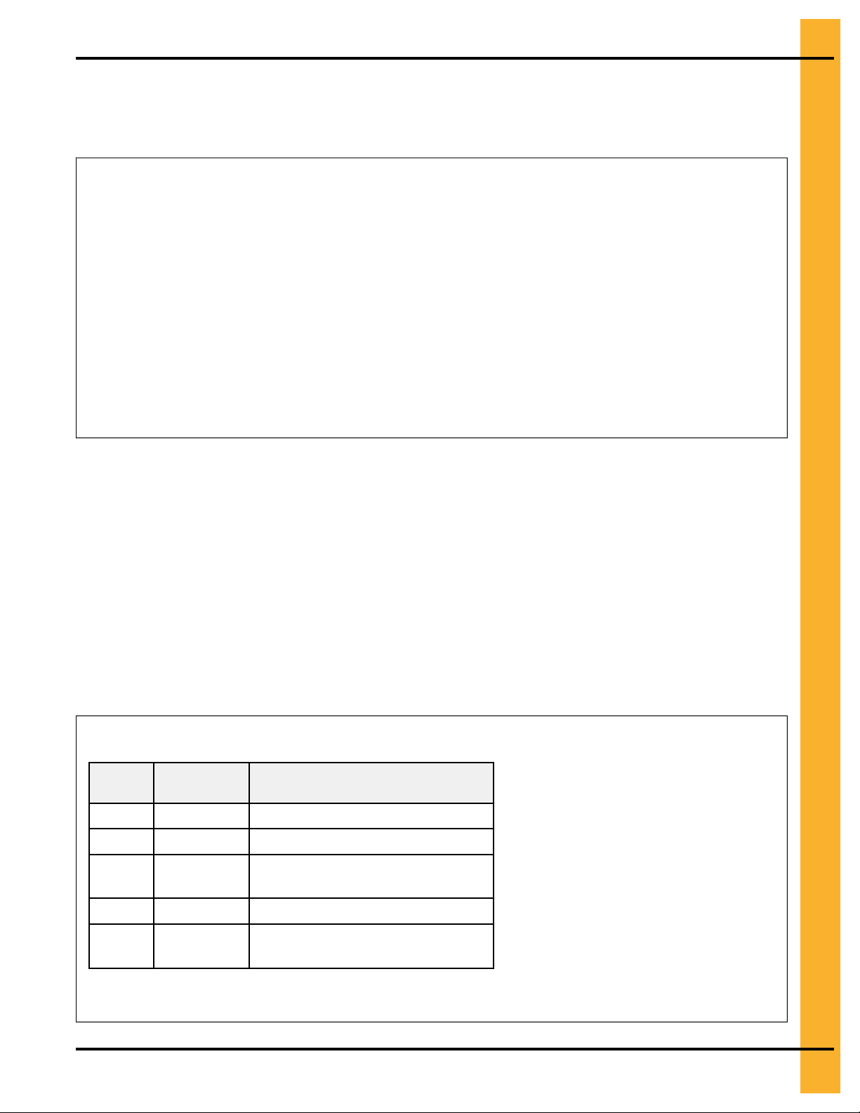
Cautionary symbols appear in this manual and on product decals. The symbols alert the user of potential
safety hazards, prohibited activities and mandatory actions. To help you recognize this information, we
use the symbols that are defined below.
Table 1-1 Description of the different cautionary symbols
Symbol Description
This symbol indicates an imminently hazardous situation which, if
not avoided, will result in serious injury or death.
This symbol indicates a potentially hazardous situation which, if not
avoided, can result in serious injury or death.
This symbol indicates a potentially hazardous situation which, if not
avoided, can result in minor or moderate injury.
6
PNEG-1891 Portable Dryers
Page 7

Table 1-1 Description of the different cautionary symbols (cont'd.)
Symbol Description
This symbol is used to address practices not related to personal
injury.
This symbol indicates a general hazard.
This symbol indicates a prohibited activity.
This symbol indicates a mandatory action.
Chapter 1: Safety Precautions
ST-0005–2
Safety Decals for Portable Dryers
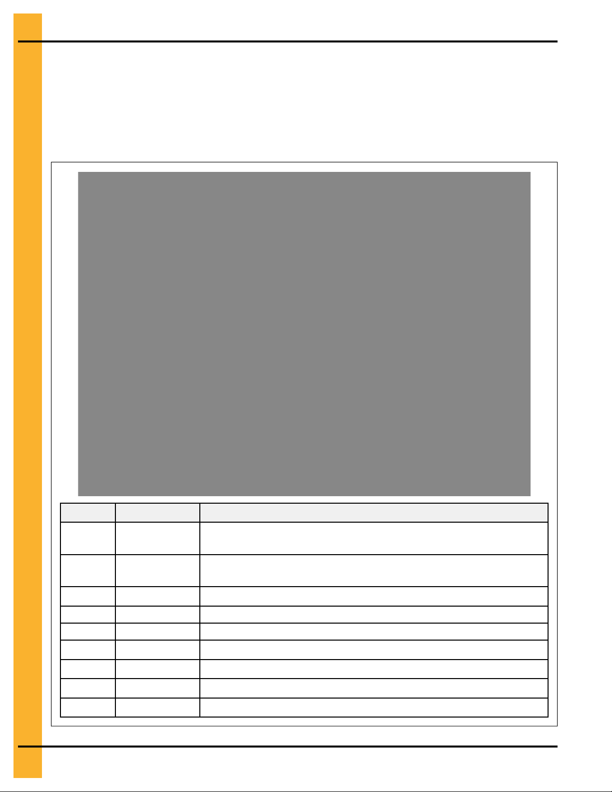
The safety decals on your grain dryer are safety indicators which must be carefully read and understood
by all personnel involved in the installation, operation, service, and maintenance of the grain dryer.
Table 1-2 Description of the grain dryer’s decals
Decal Decal No. Location
This decal appears:
• On the lid of the fan/heater control box
DC-1948
• On the front of the fan/heater control box
• Inside the dryer’s upper control box
This decal appears:
• On the bottom auger belt guard
• On the front bearing plate (visible when the bottom
auger belt guard is removed)
PNEG-1891 Portable Dryers
DC-1944
• At the rear of the dryer (for dryers equipped with the
front discharge option)
• On the top auger belt guard
• On the inside belt guard body (visible when the top
auger belt guard is removed)
7
Page 8

Chapter 1: Safety Precautions
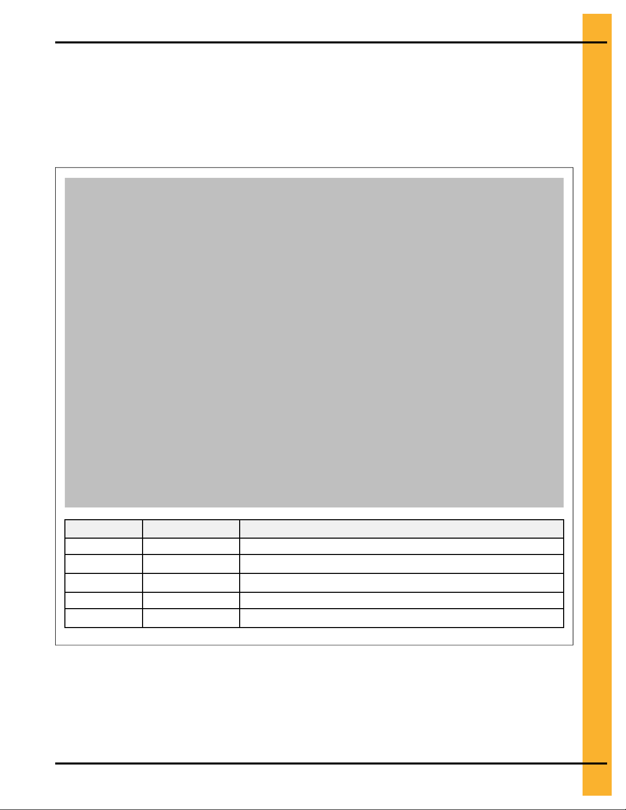
Table 1-2 Description of the grain dryer’s decals (cont'd.)
Decal Decal No. Location
This decal appears:
• On the bottom auger belt guard
DC-1945
DC-1946
DC-1947
• On the front bearing plate (visible when the bottom
auger belt guard is removed)
• At the rear of the dryer (for dryers equipped with the
front discharge option)
This decal appears:
• On the inside of the rear plenum access door
• On the outside of the rear plenum access door
This decal appears:
• Twice on the front end panel, below the fan/heater
• Twice on the rear end panel, below the rear access
door
• On the auger discharge box
DC-1943
• On the inside of the auger discharge box’s flapper lid
(next to the discharge mercury switch)
• Inside the rear access door, on the rear plenum closure door (inside the plenum)
This decal appears:
• Inside the fan/heater control box
• On the door of the dryer’s upper control box
8
PNEG-1891 Portable Dryers
Page 9

Table 1-2 Description of the grain dryer’s decals (cont'd.)
Decal Decal No. Location
DC-1949
DC-1959
Chapter 1: Safety Precautions
This decal appears on the fan/heater access door
This decal appears on the fan/heater access door
This decal appears on each of the metering roll access
doors
DC-1950
This decal appears on the hitch tongue
DC-1956
This decal appears on the hitch tongue
DC-1954
Replacing Decals
All decals located on your grain dryer must remain legible and clearly visible at all times. To replace a
damaged or missing decal, contact us to receive a free replacement.
GSI Decals
1004 E. Illinois St.
Assumption, IL. 62510
Tel: 1–217–226–4421
PNEG-1891 Portable Dryers
9
Page 10

NOTES
10
PNEG-1891 Portable Dryers
Page 11

2 Installation Guidelines
Topics Covered in this Chapter
▪ Guidelines for Transporting a Portable Dryer
▪ Guidelines for Placing a Portable Dryer
▪ Recommendations for a Single-Module Dryer Foundation
Guidelines for Transporting a Portable Dryer
To transport the dryer safely, follow the recommended guidelines and adhere to all state or provincial
towing regulations.
• Refer to Appendix A for the dryer transportation dimensions.
• Ensure that the hitch height is between 14 and 17 in. (35.6 and 43.2 cm), see Figure 2-1, page 11).
• The hitch bolt must be at least 0.75 in. (1.9 cm) in diameter and securely fastened with a locking nut,
(see Figure 2-2, page 12).
• Use washers to minimize the vertical hitch movement
• Always use a safety chain.
• Dryer must be towed empty and in accordance with applicable state or provincial regulations.
NOTE: NEVER tow dryer with grain or any other material inside of it. Never tow after top modules
have been stacked.
• Recommended tire pressure is 55-60 PSI (3.8 bar) cold.
• Ensure the wheel lug nuts are torqued at 115 to 120 ft-lb (160 Nm).
• Maximum towing speed is 45 mph (70 km/h) or the speed limit, whichever is lower.
• After the first 50 miles (80 km) and every 200 miles (300 km) thereafter, examine the dryer wheel
hub and the spindle temperature immediately after stopping
NOTE: Temperature must not exceed 150° F (65° C) or lubricant will melt.
Figure 2-1 14 and 17 in. (35.6 and 43.2 cm) towing hitch height and safety chain
PNEG-1891 Portable Dryers
11
Page 12
Chapter 2: Installation Guidelines
Figure 2-2 Hitch bolt with washer used for spacing
A Washers B Locking nut
C 0.75 in. (1.9 cm)
Guidelines for Placing a Portable Dryer
The location of existing equipment and local code requirements must be evaluated before installing the
dryer.
Things to consider when choosing a location:
• Refer to Appendix A for dryer installation dimensions.
• Consult all national and local electrical and gas codes to ensure dryer is located correctly.
• Consider the location of the wet grain supply and dry grain discharge in relationship to the dryer.
• Consider the location of the storage bins and other grain handling equipment in relationship to the
dryer.
• Consider the location of the fuel supply and electrical sources in relationship to the dryer.
• Maintain a minimum distance of at least three feet between the dryer and other structures, otherwise
air flow problems may occur.
12
Do not operate dryer in an area where combustible materials can be drawn into
WARNING
the fans or where load and unload augers can come into contact with power
lines.
Recommendations for a Single-Module Dryer Foundation
A reinforced concrete pad or similar permanent foundation is required to keep the dryer stable during
operation.
Minimum Bag Mix for Concrete Strength per Model Weight
Consider the location of the gas and electrical service locations and how the pipe and the wire need to be
positioned before pouring the concrete.
PNEG-1891 Portable Dryers
Page 13
Chapter 2: Installation Guidelines
To prevent the dryer from overturning or moving laterally, the dryer must be secured to the foundation
using anchor bolts or cables. Anchor bolts can be cast into the concrete slab and secured to the dryer
legs. The dryer can also be secured using cables and turnbuckles that are fastened to the anchors that
are installed at the edge of the concrete slab.
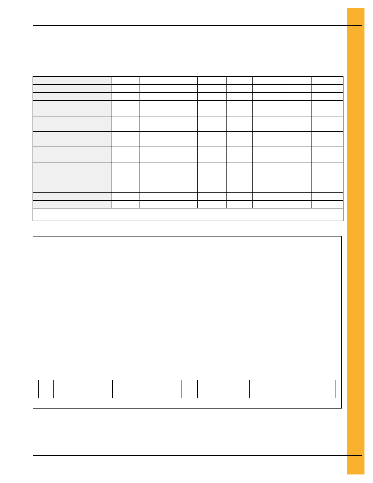
Table 2-1 General reference for concrete materials needed for each size dryer foundation.
Dryer basket length
Concrete pad size (ft x ft)
Concrete pad size (m x m)
Concrete yards (meters)
Quantity of reinforcing rods
20 in. (50.8 cm) each
Wire mesh sq—ft (sq m )
Steel legs (minimum
quantity)
Anchors
Blocks
Feet (Meters) of 2 x 6
boards
Quantity of turnbuckles
Estimated man-hours
Quantities are approximate and requirements might vary due to site elevations.
Setup times do not include site preparations and the pouring of the concrete pad.
8 12 14 16 18 20 22 26
12 x 18 12 x 22 12 x 24 12 x 26 12 x 28 12 x 30 12 x 32 12 x 36
3.7 x 5.5 3.7 x 6.7 3.7 x 7.3 3.7 x 7.9 3.7 x 8.5 3.7 x 9.1 3.7 x 9.8 3.7 x 11
5.9 (5.4) 7.1 (6.5) 7.7 (7.0) 8.3 (7.6) 8.9 (8.1) 9.2 (8.4) 10.1 (9.2)
6 7 7 8 8 8 9 10
20.0
(216)
8 10 12 12 14 14 16 18
4 6 6 6 8 8 8 10
14 18 18 18 22 22 26 30
14 (4.3) 18 (5.5) 18 (5.5) 18 (5.5) 22 (6.7) 22 (6.7) 26 (7.9) 30 (9.1)
4 6 6 6 8 8 8 10
10 14 18 18 20 22 24 28
24.5
(264)
26.7
(288)
29.0
(312)
31.2
(336)
33.4
(360)
35.7
(384)
11.3
(10.3)
40.1
(432)
Figure 2-3 Recommended locations for external equipment
A
Grain discharge
area
B Fill-hopper
C Gas pipe
location
D Electrical service
location
PNEG-1891 Portable Dryers
13
Page 14
Chapter 2: Installation Guidelines
Figure 2-4 Cross-section of the concrete for single-module dryers
A
6 in. x 6 in. (15.2 cm x 15.2
cm) reinforcing mesh wire
Figure 2-5 Side and rear view of the portable dryer
B
Grade level C 0.5 in. (1.3 cm) number 4 rein-
forcing bar
14
A Turnbuckle B
D
2 in. x 6 in. (5.8 cm x 15.2
cm) board
Front fill option C
E
8 in. X 8 in. X 16 in. (20.3 cm x 20.3 cm x 40.6 cm) concrete
blocks
Front discharge option
PNEG-1891 Portable Dryers
Page 15

3 Dryer Supports
Topics Covered in this Chapter
▪ Guidelines for Supporting the Dryer with Concrete Blocks
▪ Guidelines for Supporting the Dryer with Leg Stands
▪ Leg Stand Spacing
▪ Installing Front and Rear Anchor Plates
▪ Installing a Leg Stand to the Dryer Basket Corner
▪ Installing a Leg Stand Along the Dryer Frame
▪ Installing the Leg Stands Behind the Hitch Frame
Guidelines for Supporting the Dryer with Concrete Blocks
Before filling the dryer with grain, the dryer frame must be supported with either concrete blocks or leg
stands. If choosing concrete blocks, follow these guidelines for proper installation:
• Place a 2 x 6 or 2 x 8 board between the dryer frame and the concrete blocks to prevent the dryer
frame from fracturing the concrete blocks.
• To prevent the dryer from overturning, it must be secured to the foundation using cables and turnbuckles that are fastened to anchors in the concrete foundation.
• Do not use the wheels as supports. Wheels are for transporting the dryer when it is empty.
• Place concrete blocks six feet apart on each side of the dryer to support the dryer frame.
NOTE: A minimum of one support for every six feet of basket length is required on each side.
• The blocks must be able to support the weight of a dryer that is filled with grain.
• With the hitch tongue removed, place a concrete block under the hitch mount location.
• The hitch assembly and the fan support must remain in place during operation. The hitch assembly
and fan support are not part of the transport tie down assembly.
• Use shims to provide uniform, level support for all blocks.
• The dryer should be 16 in. (40.6 cm) off the concrete pad to accommodate for clean-out and the use
of auxiliary grain handling equipment.
PNEG-1891 Portable Dryers
15
Page 16
Chapter 3: Dryer Supports
Guidelines for Supporting the Dryer with Leg Stands
Before filling the dryer with grain, the dryer frame must be supported with either concrete blocks or leg
stands. Leg stands are optional and available in seven different sizes to accommodate various dryer
heights.
Leg Stand Height Options
Leg stands are optional and must be ordered separately from your dryer. If you do not have leg stands,
you must support the dryer with concrete blocks.
Table 3-1 Leg stand heights
Part number Leg stand height
D01–0408
D01–1046
D01–0398
D01–0399
D01–1047
D01–0582 42 in. (1066.8 mm)
D01–0761 48 in. (1219.2 mm)
16 in. (406.4 mm)
18 in. (457.2 mm)
24 in. (609.6 mm)
30 in. (762 mm)
36 in. (914.4 mm)
Leg Stand Spacing
Correct leg spacing is important to adequately support the dryer during operation. Incorrect spacing can
result in unstable operating conditions.
Leg Spacing for Standard Dryers
Starting at the back corner of the dryer (A), space legs 4 ft (1.22 m) apart and move towards the front (B).
Spacing between the front legs (C) can be 2 ft (0.61 m) or 4 ft (1.22 m), depending on the length of the
dryer.
Figure 3-1 Leg spacing on a standard dryer
16
Leg Spacing for X-Stream Dryers
PNEG-1891 Portable Dryers
Page 17
Chapter 3: Dryer Supports
Starting at both the front and back ends of the dryer (A and B), space legs 4 ft (1.22 m) apart working
towards the center of the dryer. Spacing between center legs (C) can be 2 ft (0.61 m) or 4 ft (1.22 m),
depending on the length of the dryer.
Figure 3-2 Leg spacing on an X-Stream dryer
NOTE: The number of dryer legs varies depending on the length of the dryer.
Installing Front and Rear Anchor Plates
To secure the dryer, you must install the front and rear anchor plates to the leg stand bottoms, thereby
enabling the legs to be anchored to the concrete foundation.
1. Use a flange bolt (C) and a flange nut (D) to attach the rear leg anchor plate (A) to the bottom of the
leg stand (E).
2. Position the front leg anchor plate (B) below the rear leg anchor plate (A), and use two flange bolts
(C) and flange nuts (D) to attach the anchor plate to the front of the leg stand (E).
3. Secure the leg stand (E) to the concrete foundation using concrete anchor bolts (not supplied).
Figure 3-3 Leg anchor plate assembly
Callout
A BLK-10057 Rear leg anchor plate
B BLK-10058 Front leg anchor plate
C S-6606 5/16 in. - 18 X 3/4 in. zinc grade 5
Part
number
Description
flange bolt
D
E D01–xxxx
PNEG-1891 Portable Dryers
S-3611 5/16 in. –18 grade 2 flange nut
For leg stand, refer to Leg Stand
Height Options
17
Page 18

Chapter 3: Dryer Supports
Installing a Leg Stand to the Dryer Basket Corner
If not using concrete blocks, you must install leg stands to the dryer frame at the dryer basket corners to
support the dryer.
What You Should Know
The additional width of the hitch bracket requires the use of an extra shim to install the legs located at the
dryer frame corners.
To install a leg stand to the dryer basket corner:
1. Remove the two existing bolts and nuts from the dryer frame corner (E and F).
2. Align the holes in leg stand (H) with the holes in the dryer frame corner, and fasten in place using the
bolts and nuts that were previously removed (E and F).
3. Align the top hole in the leg stand with the hole in the basket corner leg (G).
4. Fasten the legs together using bolt (B), washer (C), two shims (A), and nut (D).
18
PNEG-1891 Portable Dryers
Page 19
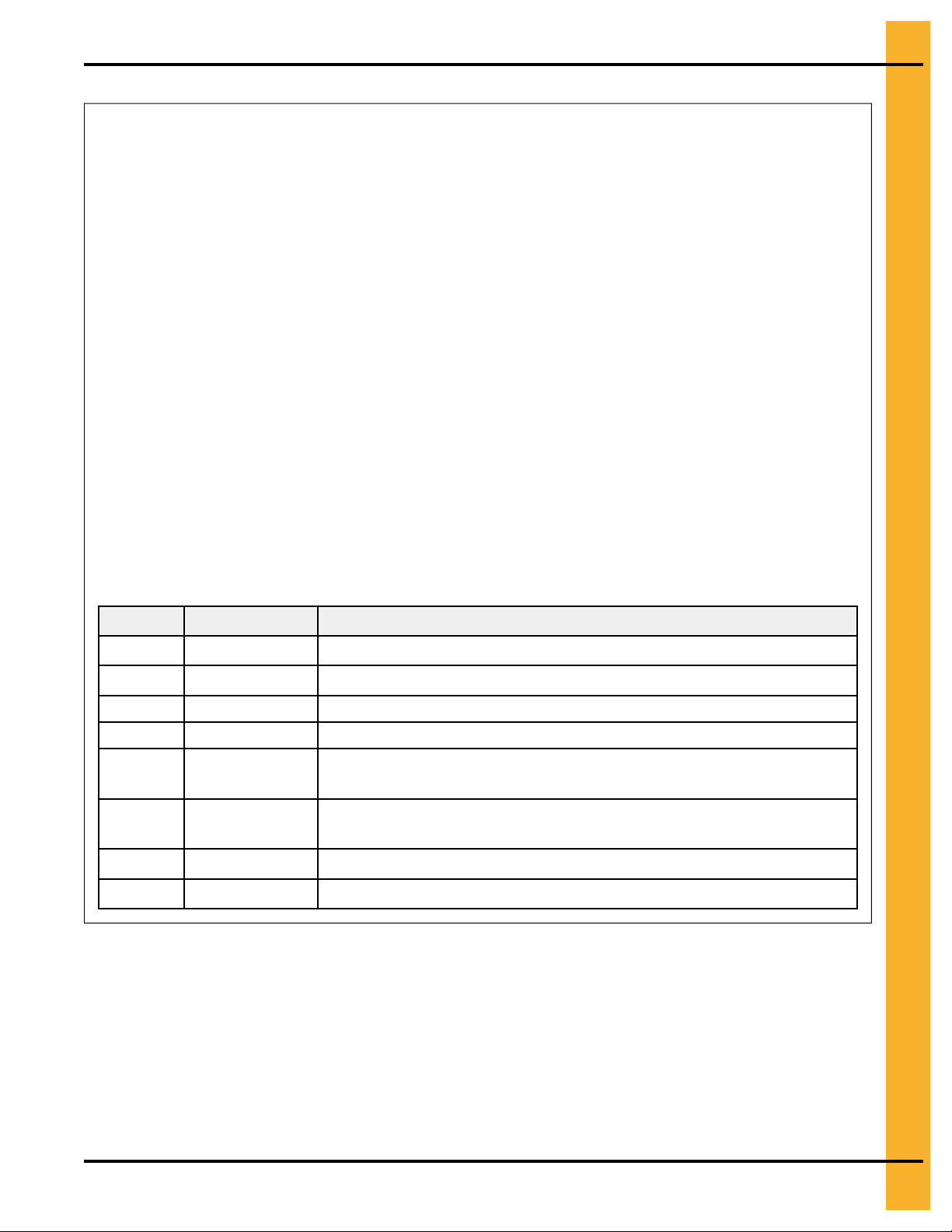
Figure 3-4 Installing a leg stand to the dryer basket corner
Chapter 3: Dryer Supports
Callout
A D01–1221 Shim dryer stand to dryer
B
C S-2121 1/2 in. X 1 3/8 in. flat washer
D
E S-3883 Original bolts installed on dryer (1/2 in. - 13 X 1 3/4 in. YDP grade 8
F
G D01–0007 Basket corner leg
H D01–xxxx For leg stand, refer to Leg Stand Height Options
Part number Description
S-3883 1/2 in. - 13 X 1 3/4 in. YDP grade 8 HHTB bolt
S-8315 1/2 in. - 13 zinc lock nut
HHTB bolt)
S-6493 Original nuts installed on dryer (1/2 in. - 13 zinc grade 2 deformed
lock nut)
Installing a Leg Stand Along the Dryer Frame
If not using concrete blocks, you must install leg stands to the dryer frame to support the dryer.
1. Remove the two bolts and nuts from the dryer frame at the location where the leg stand is to be
installed (A and B).
PNEG-1891 Portable Dryers
19
Page 20
Chapter 3: Dryer Supports
2. Align the holes in the leg stand (G) with the holes in the dryer frame, and fasten in place using the
bolts and nuts that were previously removed (A and B).
3. Align the top hole in the leg stand (G) with the hole in the basket leg (F).
4. Fasten the legs together using a bolt (E), shim (C), and nut (D).
5. For a secure fit, use the shim plates (H) to make any minor adjustments to the leg height.
Figure 3-5 Installing leg stands along dryer frame
20
Callout Part number Description
A
S-3883 Original bolts installed on dryer (1/2 in. - 13 X 1 3/4 in. YDP grade 8
HHTB bolt)
B S-6493 Original nuts installed on dryer (1/2 in. - 13 zinc grade 2 deformed
lock nut)
C D01–1221 Shim dryer stand to dryer
NS S-2121 1/2 in. X 1 3/8 in. flat washer
D S-8315 1/2 in. -13 zinc lock nut
E S-3728 1/2 in. - 13 X 1 1/2 in. YDP grade 8 or 8.2 HHTB bolt
F D01–0007 Basket corner leg
G D01–xxxx For leg stand, refer to Leg Stand Height Options
H
FC-42077 Shim plate
PNEG-1891 Portable Dryers
Page 21
Chapter 3: Dryer Supports
Installing the Leg Stands Behind the Hitch Frame
Use leg stands behind the hitch frame to appropriately support the dryer.
1. Position the leg stands (E) behind the hitch frame, and align them with the holes in the rear hitch
cross channel (D).
2. Fasten the legs to the channel using two bolts (B), four washers (C), and two nuts (A) per each leg.
Figure 3-6 Installing leg stands to the hitch assembly
Callout
A
B
C S-2121 1/2 in. X 1 3/8 in. type A plated flat washer
D D01–2481 Rear hitch cross channel
E D01–xxxx
PNEG-1891 Portable Dryers
Part number Description
S-8315 1/2 in. -13 zinc lock nut
S-3728 1/2 in. - 13 X 1 1/2 in. YDP grade 8 or 8.2 HHTB bolt
For leg stand, refer to Leg Stand Height Options
21
Page 22

NOTES
22
PNEG-1891 Portable Dryers
Page 23

4 Hitch Ladder
Topics Covered in this Chapter
▪ Hitch Ladder Packages
▪ Installing the Hitch Ladder Support Bracket to the Hitch Channel
▪ Installing the Ladder Standoff Bracket to the Hitch Ladder Support Bracket
▪ Installing the Ladder to the Ladder Standoff Brackets
▪ Installing the End Cap to the Ladder
Hitch Ladder Packages
Hitch ladders are available in three different sizes. You must use the ladder package that is specific to
your dryer size.
Table 4-1 Available hitch ladder packages
Part number Description
2FOOTRF 2 foot roll formed ladder assembly used for 16,18, and 24 inch dryer heights
3FOOTRF 3 foot roll formed ladder assembly used for 30 and 36 inch dryer heights
4FOOTRF 4 foot roll formed ladder assembly used for 42 and 48 inch dryer heights
PNEG-1891 Portable Dryers
23
Page 24
Chapter 4: Hitch Ladder
Installing the Hitch Ladder Support Bracket to the Hitch Channel
The hitch ladder is used to access the front of the dryer opposite of the control box side of the dryer.
1. Install the hitch ladder support bracket (A) to the center hole pattern on the hitch channel.
2. Fasten bracket (A) to the hitch channel, using flange bolts (B) and flange nuts (C).
Figure 4-1 Installing the hitch ladder support bracket to the hitch channel
24
Callout
A D01–2755 Hitch ladder support bracket
B
C S-8506 1/2 in. - 13 zinc flange nut
Part number Description
S-9062 1/2 in. - 13 X 1 1/4 in. zinc grade 5 flange bolt
PNEG-1891 Portable Dryers
Page 25

Chapter 4: Hitch Ladder
Installing the Ladder Standoff Bracket to the Hitch Ladder Support Bracket
The ladder standoff brackets secures the ladder to the ladder support bracket, thus ensuring safe access
to the front of the dryer.
1. Align the holes in the ladder standoff brackets (B) with the holes on the side of the hitch ladder support bracket (A).
2. Fasten the four standoff brackets (B) to the hitch ladder support bracket (A) using flange bolts (C)
and flange nuts (D.)
Figure 4-2 Installing the ladder standoff bracket to the hitch ladder support bracket
Callout
A D01–2755 Hitch ladder support bracket
B LDR-4341 Ladder standoff bracket
C S-6606 5/16 in. - 18 X 3/4 in. zinc grade 5 flange bolts
D
PNEG-1891 Portable Dryers
Part number Description
S-3611 5/16 in. - 18 grade 2 flange nut
25
Page 26

Chapter 4: Hitch Ladder
Installing the Ladder to the Ladder Standoff Brackets
Standoff brackets are used to support the ladder along it’s vertical length and secure the ladder to the
equipment.
1. Install the carriage bolt (C) through the standoff wedge (B).
2. Hook the standoff wedge assembly (B) under the ladder edge (E).
3. Place the standoff bracket (A) onto the carriage bolt (C) and fasten in place with flange nut (D).
Leave the flange nut (D) loose to allow the ladder to slide into position before fully tightening.
4. Install all standoff brackets (A) and adjust the ladder vertically into position.
5. Fully tighten the carriage bolts (C) and flange nuts (D).
Figure 4-3 Detail of the standoff bracket
Callout
A LDR-4314 Ladder standoff bracket
B LDR-4198 Ladder standoff wedge
C S-3550 5/16 in. x 1 in. carriage bolt
D S-3611 5/16 in. flange nut
Part
Number
Description
Installing the End Cap to the Ladder
The end cap helps to protects your hands from the sharp edges on the ends of the ladder.
26
1. Install the end caps (A) to both the right and left side of the ladder by snapping the end caps (A) into
the top of the ladder.
2. Secure the end cap (A) in place using a flange bolt (B) and flange nut (C).
PNEG-1891 Portable Dryers
Page 27

Figure 4-4 End cap assembly
Chapter 4: Hitch Ladder
Callout
A LDR-5011 Ladder end cap
B
C S-3611 5/16 in. - 18 grade 2 flange nut
Part number Description
S-7470 5/16 in. - 18 X 1 in. zinc grade 5
flange bolt
PNEG-1891 Portable Dryers
27
Page 28

NOTES
28
PNEG-1891 Portable Dryers
Page 29

5 Rear Access Ladder
Topics Covered in this Chapter
▪ Installing the Rear Ladder Support Brackets
▪ Installing the Ladder Standoff Brackets to the Rear Ladder Support Brackets
Installing the Rear Ladder Support Brackets
The rear ladder support brackets attach directly to the dryer and support the ladder standoff brackets.
1. Locate the two upper rear ladder bracket installation locations (A) and remove the existing hardware
(B and C).
2. Install one upper rear ladder bracket (A) by aligning it with the bottom bolt in the door frame (B), and
fasten with the previously removed hardware.
3. Install the second upper rear bracket (A) by aligning it with the middle bolt in the gusset plate (C),
and fasten with the previously removed hardware.
4. Align the holes in the lower rear bracket (D) with the holes in the dryer frame and fasten with three
flange bolts (E) and flange nuts (F).
PNEG-1891 Portable Dryers
29
Page 30

Chapter 5: Rear Access Ladder
Figure 5-1 Installing the rear ladder support brackets
30
Callout
A D01–2691 Upper rear ladder bracket
B NA
C
D D01–2692 Lower rear bracket
E
F
Part number Description
Existing hardware — bottom bolt in door frame
NA Existing hardware — lower rear bracket
S-9067 3/8 in. - 16 X 3/4 in. zinc grade 5 flange bolt
S-968 3/8 in. -16 zinc grade 5 flange nut
PNEG-1891 Portable Dryers
Page 31

Chapter 5: Rear Access Ladder
Installing the Ladder Standoff Brackets to the Rear Ladder Support Brackets
The ladder standoff brackets allow the ladder to be easily adjusted and secured to the dryer.
1. Install the ladder standoff brackets (A) to the lower rear ladder support bracket (D), using carriage
bolts (B) and flange nuts (C).
2. Install the ladder standoff brackets (A) to the upper rear ladder support brackets (E), using carriage
bolts (B) and flange nuts (C).
3. Install the ladder to standoff brackets, (see Installing the Ladder to the Ladder Standoff Brackets,
page 26).
4. Install the end caps to the ends of the ladder, (see Installing the End Cap to the Ladder, page 26).
Figure 5-2 Installing the ladder standoff bracket to rear ladder support bracket
Callout
A LDR-4341
B
C S-3611 5/16 in. - 18 grade 2 flange nut
D D01–2692 Lower rear ladder bracket
E D01–2691 Upper rear ladder bracket
PNEG-1891 Portable Dryers
Part number Description
S-3550 5/16 in. X 1 in. carriage bolt
Standoff bracket
31
Page 32

NOTES
32
PNEG-1891 Portable Dryers
Page 33

6 Installing the Wet Bin
Topics Covered in this Chapter
▪ Raising the Load Auger
▪ Securing the Dryer Wet Bin Sides
▪ Installing the Belt Guard and Load Motor
▪ Installing the Drive Sheaves and Belts
▪ Installing the Belt Guard Cover
▪ Installing the Grain Intake Hopper
▪ The Parts of the Dryer Wet Bin
Raising the Load Auger
You must raise the load auger before you can install the dryer wet bin.
1. To raise the load auger:
• For dryers eight ft (2.44 m) use the handrails (A)
Figure 6-1 Handrail location for dryers eight ft (2.44 m) in length.
A
• For dryers twelve ft (2.66 m) or longer, turn the turnbuckles on the lift kit (B)
PNEG-1891 Portable Dryers
Handrails for 8 ft (2.44 m) dryer
33
Page 34

Chapter 6: Installing the Wet Bin
Figure 6-2 Turnbuckle location for dryers twelve ft (2.66 m) and longer
B
Lift kit turnbuckles for twelve ft (2.66 m) and longer dryers
2. Bolt the top angle brackets (D) to the angle brackets already installed, positioning the brackets
back-to-back. Brackets are located on the front and rear of the dryer, (see Figure 6-3, page 34).
3. Bolt the load auger housing channel (C) to the front and rear of the ends of the dryer wet bin.
Figure 6-3 Angle brackets and housing channels
34
C
Top auger housing channel D Top angle bracket
4. Once the auger assembly is securely bolted, unbolt the lift kit legs and lower them back into their
shipping position.
PNEG-1891 Portable Dryers
Page 35

Chapter 6: Installing the Wet Bin
Securing the Dryer Wet Bin Sides
After having raised the load auger, you must install the side panels so that the dryer wet bin can receive
and hold the incoming grain.
1. At each end of the dryer, attach the end plate connectors to the corners of the dryer wet bin, (see
Figure 6-4, page 35).
2. Raise the dryer wet grain bin sides (B) and secure them to the end plate connectors (A), (see Figure
6-5, page 36).
NOTE: Do not connect the side of the dryer wet bin that is adjacent to the load auger motor. Leave
this side open to allow for easy access when attaching the belt guard body.
Figure 6-4 The end plate connectors of the dryer wet bin
A End plate connector
PNEG-1891 Portable Dryers
35
Page 36

Chapter 6: Installing the Wet Bin
Figure 6-5 Connections for the dryer wet bin sides
B Dryer wet bin side
Installing the Belt Guard and Load Motor
To protect you from the load motor belt, you must install the belt guard after installing the load motor.
1. Install the belt guard mounting bracket to the top of the dryer wet bin.
2. Lift the load motor and install 0.50 in. x 6 in. turnbuckles to the motor mount (D01–0173) and motor
mount anchor bracket (D01–0170) with two turnbuckle pins and two cotter pins.
3. Install the three bolts for the belt guard body.
4. Place the belt guard body onto the bolts, centering the cutout in the belt guard body over the drive
shaft of the load motor.
5. Loosely secure with nuts. These bolts will be tightened after the belt is adjusted for clearance.
36
PNEG-1891 Portable Dryers
Page 37

Figure 6-6 Bolt locations for Belt Guard Body
Chapter 6: Installing the Wet Bin
Installing the Drive Sheaves and Belts
To ensure that the load auger rotates, you must install the drive sheaves and belts. The motor turns the
drive sheaves and belts, and the drive sheaves and belts turn the load auger.
1. Insert the key into the keyway on the auger drive shaft.
2. Place 16 inch sheave (D52–0001) on the auger drive shaft.
PNEG-1891 Portable Dryers
37
Page 38

Chapter 6: Installing the Wet Bin
3. Insert the 1–1/2 inch split tapered Q1 bushing on the auger drive shaft and infix the bushing with a
wooden or non-metal mallet.
4. Install three bolts into the bushing. If necessary, smooth the load auger drive shaft with hardware
cloth.
5. Insert the key into keyway and slide the motor drive sheave onto the drive shaft of the load motor.
6. Secure the drive sheave with the setscrew.
7. Thread the two BX97 belts from the motor drive pulley to the 16 inch sheave.
8. Check the alignment of the belts and sheaves to ensure that they are aligned.
9. To tighten belts, turn the turnbuckle on the anchor bracket of the motor mount.
10.Adjust the clearance of the belt guard body so that there is no contact with moving parts and tighten
the adjustment hardware.
Figure 6-7 Load motor sheave and motor adjustment turnbuckle
38
A Load motor sheave B
Motor adjustment turnbuckle
Installing the Belt Guard Cover
To easily remove the cover when performing maintenance to the drive belts and sheaves, you must install
the belt guard cover using its latches.
1. Insert the tabs on the belt guard cover into the slots on the belt guard body.
2. Engage the latches, one on the top and two on the bottom, (see Figure 6-8, page 39).
3. Install the dryer wet bin side that was left open to allow for easy access to the belt guard body.
PNEG-1891 Portable Dryers
Page 39

Chapter 6: Installing the Wet Bin
Figure 6-8 Latches for the belt guard cover
Installing the Grain Intake Hopper
To ensure that the dryer receives the incoming wet grain, you must connect the grain intake hopper
between the dryer wet bin and the equipment that supplies the wet grain.
1. Locate the hopper assembly (D01–0193) over the grain intake opening at the top rear of the dryer.
2. Connect the hopper assembly to the dryer wet grain bin by using six 1/4 in. x 3/4 in. self-drilling
screws (S-6497), six 5/16 in. x 3/4 in. flange bolts (S-6606), and six 5/16 in. flange nuts (S-3611).
Figure 6-9 Hopper assembly and hopper installation location
A
Hopper assembly (D01–0193)
B
Hopper installation location on load auger
assembly
PNEG-1891 Portable Dryers
39
Page 40

Chapter 6: Installing the Wet Bin
The Parts of the Dryer Wet Bin
Shows the dryer wet bin parts for easy identification of parts.
Figure 6-10 The parts that make up the dryer wet bin
40
PNEG-1891 Portable Dryers
Page 41

Table 6-1 Part descriptions of the dryer wet bin
Chapter 6: Installing the Wet Bin
Part
Callout
1
2
3 & 4 D01-1182-Y
3
4 D01-0453
5
6 D01-0044
7 D01-0156
8 D01-1526
9 D01-0155
10 NA
11 D01-0464 Belts BX97 2
12 D32-0019
13 D52-0001
Number
D01-0465
D01-0452Y
Description
Dryer wet bin hardware package
Turnbuckle, 0.50 in. X 6 in.
Top auger belt guard assembly (includes #3, #4, and #5)
Top auger belt guard cover (not shown)
Top auger belt guard body
Belt guard assembly mounting hardware (see Table 6-2, page 41)
Top angle bracket, front and rear
Top auger housing channel
Wet bin end plate connector
Belt guard mounting bracket
Motor shaft sheave (determined by the dryer model)
Bushing Q1 - 1.50 in. split taper (for auger shaft sheave and includes
hardware)
Sheave, 16 in. grip-belt 2 groove
Qua-
ntity
1
1
1
1
1
2
2
4
1
1
1
1
14
Table 6-2 Hardware packages for the belt guard of the dryer wet bin
Part
number
S-6501 3/8 in. - 16 X 4 in. bolt 3
S-968
S-248 3/8 in. flat washer 4
S-6606
S-3611
S-3949 3/8 in. - 16 X 1 in. bolt 2
S-4663
D01-0193Y
Description
3/8 in. - 16 flange whiz nut
5/16 in. - 18 X 3/4 in. flange bolt
5/16 in. - 18 flange nut
3/8 in. - 16 locking nut
Hopper assembly
Quantity
9
3
3
2
1
PNEG-1891 Portable Dryers
41
Page 42

NOTES
42
PNEG-1891 Portable Dryers
Page 43

7 Moisture Sampler
Topics Covered in this Chapter
▪ Installing the Moisture Sampler
▪ Blower Cover Assembly Parts (D04–1016)
▪ Moisture Sampler Hose Parts (D04–1023)
▪ 220V Moisture Sampler Blower Wiring Diagram
▪ 400V Moisture Sampler Blower Wiring Diagram
▪ 480V Moisture Sampler Blower Wiring Diagram
▪ 600V Moisture Sampler Blower Wiring Diagram
Installing the Moisture Sampler
These instructions cover the moisture blower kits for 220V, 440V, 380V and 575V portable dryers.
1. Install the blower mount bracket (A) to the dryer using the middle set of holes in the center flange (B)
and secure them using bolts (C) and nuts (D).
Figure 7-1 Installing the blower mount bracket to the Dryer
A
Blower mount bracket (D01-2958) C 5/16 in. x 3/4 in. flange bolt (S-6606)
B
Center flange
D
5/16 in. flange nut (S-3611)
2. Install the top two bolts (C) to the blower assembly brackets (F) leaving space between the bolt
head and nut.
PNEG-1891 Portable Dryers
43
Page 44

Chapter 7: Moisture Sampler
3. Slide the bolt heads into the slots on the blower mount bracket (A).
4. Install the bottom two bolts (C) in the blower assembly brackets and tighten all the bolts.
Figure 7-2 Installing the blower to the bracket
A
Blower mount bracket (D01-2958)
B
Center flange
C 5/16 in. x 3/4 in. flange bolt (S-6606)
D
5/16 in. flange nut (S-3611)
E
Blower assembly (D04-1016)
F
Blower assembly bracket (D01-2952 and D01-2959)
5. Install the conduit hangers (G) into existing bolt holes on the dryer using screws (K).
44
PNEG-1891 Portable Dryers
Page 45

Figure 7-3 Conduit hangers installation
Chapter 7: Moisture Sampler
G Conduit hangers (S-6643)
K
Self-drilling screw (S-280)
L
5/16 in. x 1 in. bolt (S-1196)
M
5/16 in. hex nut (S-400)
6. Install the pipe conduit (H) between the blower (E) and the unload (I) using a hose clamps (J) to
fasten together each section. Guide the conduit through the conduit hangers (G).
PNEG-1891 Portable Dryers
45
Page 46

Chapter 7: Moisture Sampler
Figure 7-4 Hose installation
E
Blower assembly (D04-1016)
G Conduit hangers (S-6643)
H
Pipe conduit (D04-1023)
I Unload
J
Hose clamp (AP-0583)
7. Install the electrical conduit (N) from the blower to junction box (O). Secure conduit with 1/2" clamp
(HH-1096).
8. Install the electrical box to the gusset plate using four screws (S-995) and hex nuts (S-7931).
Make sure all power is locked out before beginning the work.
DANGER
9. Install wires through the electrical conduit (N) and connect the electrical wires according to the
appropriate wiring diagrams. For wiring diagrams, seeFigure 7-6 Wiring Diagrams, page 50
46
PNEG-1891 Portable Dryers
Page 47

Figure 7-5 Conduit layout
Chapter 7: Moisture Sampler
B
Blower assembly (D04-1016)
H
Pipe conduit (D04-1023) O
J
Hose clamp (AP-0583)
N Electrical conduit
Junction Box
P
Flexible hose (D01–2973)
NOTE: If the dryer has an auger extension, an additional piece of flexible hose (D03–1190) will be
required. The longer lengths can be created by twisting one end of hose into another and
ensuring the couplers are not necessary to extend the hose. Also, D03–1199 (12 - 15 in.
hose clamp) can be used to support the flex hose by securing it to the auger extension.
PNEG-1891 Portable Dryers
47
Page 48

Chapter 7: Moisture Sampler
Blower Cover Assembly Parts (D04–1016)
Table 7-1 Blower Cover Assembly Part List (D04–1016)
Ref # Part #
1
2
3 D01-2959 Blower Mount Short Bracket
4
5 D03-1181
6 D01-2954
7
8 S-6606
9 S-3611
10 S-280
11
12
13 S-7375
D04-1017-BK Blower Cover Weldment
D01-2952
D01-2953 Blower Mount Bracket
D04-1021-BK
D03-1189
D02-0028
Description
Moisture Sampler Blower Housing Bracket
Blower 120V VAC, 50/60 Hz
Seal Plate, Blower Housing
10" Vertical Cap Black
Flange Bolt 5/16"-18 x 3/4" ZN Grade 5
Flange Nut 5/16"-18 YDP Grade 2
Screw, SDS #10-16 x 5/8" HWH ZN
Filter, Reusable Rigid Polyester Air, 12" x 12" x 1"
Clevis Pin 5/16" x 1-3/4" Long Zinc
Cotter Pin, Hairpin 0.93" Wire Diameter
Qty.
1
1
1
1
1
1
1
15
15
4
1
1
1
48
PNEG-1891 Portable Dryers
Page 49

Moisture Sampler Hose Parts (D04–1023)
Chapter 7: Moisture Sampler
Table 7-2 Moisture Sampler Hose Parts (D04–1023)
Ref # Part #
1
2
3 D03-1203
4
5 D03-1192
6 D01-2973
7
D03-1205
D01-2972
D01-2971
AP-0583
Description
Fitting, Flexible Pipe Coupler, 1-1/2" x 3-7/16" Long
Pipe, Black ABS 1-1/2" x 6-1/4"
Fitting, Flexible Pipe Elbow, 1-1/2" 90°
Pipe, Black ABS 1-1/2" x 70"
Coupler, Outdoor Bend and Stay Duct Hose, for 2" I.D., 2-1/4" O.D.
Hose, Flexible, 2" x 12" (Extended Length)
Hose Clamp, SAE 36 - Stainless Steel 1-13/16" - 2-3/4"
Qty
1
2
2
1
2
1
2
PNEG-1891 Portable Dryers
49
Page 50

Chapter 7: Moisture Sampler
220V Moisture Sampler Blower Wiring Diagram
Figure 7-6 220V blower motor wiring diagram
50
PNEG-1891 Portable Dryers
Page 51

Chapter 7: Moisture Sampler
400V Moisture Sampler Blower Wiring Diagram
Figure 7-7 400V blower motor wiring diagram
PNEG-1891 Portable Dryers
51
Page 52

Chapter 7: Moisture Sampler
480V Moisture Sampler Blower Wiring Diagram
Figure 7-8 480V blower motor wiring diagram
52
PNEG-1891 Portable Dryers
Page 53

Chapter 7: Moisture Sampler
600V Moisture Sampler Blower Wiring Diagram
Figure 7-9 600V blower motor wiring diagram
PNEG-1891 Portable Dryers
53
Page 54

NOTES
54
PNEG-1891 Portable Dryers
Page 55

8 Power Supply
Topics Covered in this Chapter
▪ Guidelines for Supplying Adequate Power
▪ Installing the Machine-to-Earth Grounding Rod
▪ Guidelines for Powering Auxiliary Conveyors
▪ Specifications for the Electrical Load on a Portable Dryer
Guidelines for Supplying Adequate Power
An adequate power supply and proper wiring are important factors for ensuring maximum performance
and long life of the dryer.
• Ensure that electrical service is adequate to prevent low-voltage damage to motors and control circuits. Refer to Specifications for the Electrical Load on a Portable Dryer, page 57 for power supply
requirements.
All dryers are equipped with a main electrical disconnect switch on the main
WARNING
dryer.
control box. This switch turns off the main power to the dryer. Make sure to turn
off the main electrical disconnect switch before inspecting or servicing the
• Advise the service representative of the local power supplier that an additional load will be placed on
the line.
• Considering the total horsepower load, check the KVA rating of transformers.
• The voltage drop during a motor start must not exceed 14% of the normal voltage. The power
supply wiring, main switch equipment, and transformers must provide adequate motor startup and
operating voltage.
• Verify that the motor is within 8% of the normal voltage when it is operating at full speed.
• Check the electrical load information for HP ratings and the maximum amp loads.
Installing the Machine-to-Earth Grounding Rod
To help protect circuit boards, the variable frequency drive (VFD), and the ignition system if electrical
short circuits occur, you must install a machine-to-earth grounding rod.
What You Should Know
The machine-to-earth grounding rod that is located at the power pole does not provide adequate grounding for the dryer. The grounding rod that you install must be in accordance with local requirements.
PNEG-1891 Portable Dryers
55
Page 56

Chapter 8: Power Supply
Do not install the machine-to-earth grounding rod into dry soil. The soil must be wet
CAUTION
1. Place the machine-to-earth grounding rod within 8 feet (2.4 meters) of the dryer.
2. Dig a hole large enough to hold 2 gallons (7.6 liters) of water.
3. Fill the hole with water and insert the rod through the water and into the ground.
4. Move the rod up and down, working the water into the ground.
The rod is fully inserted into the ground and an appropriate contact with the surrounding soil is
assured.
5. Using an appropriate clamp, connect the bare, copper ground wire to the grounding rod.
6. Connect the ground wire to the control panel using the ground lug that is provided in the control box.
NOTE: Use a minimum grade of number six solid, bare, copper wire. The ground wire must not
Figure 8-1 Grounding rod installation
to ensure good contact with the surrounding soil, thereby making an appropriate
ground.
have any breaks or splices. Do not use insulated wire for grounding applications.
56
A Bare, copper ground
wire
B
Clamp C
Machine-to-earth grounding rod
PNEG-1891 Portable Dryers
Page 57

Chapter 8: Power Supply
Guidelines for Powering Auxiliary Conveyors
Before you can operate the auxiliary conveyors, you must ensure that adequate power is available.
• The auxiliary load and auxiliary unload augers or conveyors can be wired directly to the dryer.
• If an auxiliary motor is larger than recommended, it must be powered from a source outside the
dryer and must use a separate contactor and overload protection device for each motor. However,
you can operate the auxiliaries through the control panel.
• Refer to Specifications for the Electrical Load on a Portable Dryer, page 57 for the maximum horsepower and amps that can be wired to the dryer.
Specifications for the Electrical Load on a Portable Dryer
These charts provide information for you to ensure that the grain dryer and the auxiliary equipment are
supplied with adequate power.
It is recommended that you contact the local power company and have a representative verify the installation to make sure that the wiring is compatible with their system and adequate power is supplied to the
unit. The only equipment connected to the recommended service amps must be the grain dryer. You must
adhere to all national and local electrical regulations. (Refer to the National Electrical Code Standard
handbook created by the National Fire Protection Association). A qualified electrician must make all electrical wiring installations.
Table 8-1 Specifications for the electrical load on a portable dryer
Dryer
model
1108
D190
1112
D270
Voltage
1 PH 230V
3 PH 220V
3 PH 440V
1 PH 230V
3 PH 220V
3 PH 440V
Motor HP
Load auger
Unload auger
Fan 10 to 12 48 100
(2) Auxiliary (2) 7.5
Load auger
Unload auger
Fan 10 to 12 33 60
(2) Auxiliary (2) 7.5
Load auger
Unload auger
Fan 10 to 12 16.5 60
(2) Auxiliary (2) 7.5
Load auger
Unload auger
Fan 10 to 17 78 100
(2) Auxiliary (2) 7.5
Load auger
Unload auger
Fan 15 39 60
(2) Auxiliary (2) 7.5
Load auger
Unload auger
Fan 15 19.5 60
(2) Auxiliary (2) 7.5
Fuel Load
Amps
1.5 8
1 6.5 60
62 *
1.5 5
1 3.4 50
40 *
1.5 2.5
1 1.7 60
20 *
2 14
1.5 8 60
62 *
2 6.2
1.5 5 50
40 *
2 3.1
1.5 2.5 60
20 *
Maximum amps
with auxiliaries
153 62.5 200
104 41.4 150
57 20.7 150
196 100 300
114 50.2 175
62 25.1 150
Minimum
amps
Recommended
service in amps
Branch breaker
in amps
60
50
60
60
50
60
PNEG-1891 Portable Dryers
57
Page 58

Chapter 8: Power Supply
Table 8-1 Specifications for the electrical load on a portable dryer (cont'd.)
Dryer
model
1114
D320
1116
D370
1118
D400
1120
D460
Voltage
1 PH 230V
3 PH 220V
3 PH 440V
1 PH 230V
3 PH 220V
3 PH 440V
3 PH 220V
3 PH 440V
3 PH 220V
3 PH 440V
Motor HP
Load auger
Unload auger
Fan 10 to 17 78 100
(2) Auxiliary (2) 7.5
Load auger
Unload auger
Fan 15 39 60
(2) Auxiliary (2) 10
Load auger
Unload auger
Fan 15 19.5 60
(2) Auxiliary (2) 10
Load auger
Unload auger
Fan 10 to 17 78 100
(2) Auxiliary (2) 7.5
Load auger
Unload auger
Fan 15 39 60
(2) Auxiliary (2) 10
Load auger
Unload auger
Fan 15 19.5 60
(2) Auxiliary (2) 10
Load auger
Unload auger
Fan 20 50 90
(2) Auxiliary (2) 10
Load auger
Unload auger
Fan 20 25 60
(2) Auxiliary (2) 10
Load auger
Unload auger
Fan 25 64 90
(2) Auxiliary (2) 15
Load auger
Unload auger
Fan 25 32 60
(2) Auxiliary (2) 15
Fuel Load
Amps
5 26
5 26 100
62 *
5 13.2
5 13.2 60
52 *
5 6.6
5 6.6 60
26 *
5 26
5 26 100
62 *
5 13.2
5 13.2 60
52 *
5 6.6
5 6.6 60
26 *
5 13.2
5 13.2 60
52 *
5 6.6
5 6.6 60
26 *
7.5 20
7.5 20 90
78 *
7.5 10
7.5 10 60
39 *
Maximum amps
with auxiliaries
231 130 350
145 65.4 200
78 32.7 150
231 130 350
145 65.4 200
78 32.7 150
158 76.4 250
84 38.2 150
219 104 300
115 52 200
Minimum
amps
Recommended
service in amps
Branch breaker
in amps
100
60
60
100
60
60
60
60
90
60
58
PNEG-1891 Portable Dryers
Page 59

Table 8-1 Specifications for the electrical load on a portable dryer (cont'd.)
Dryer
model
1122
D511
1126
D601
1214
2120
1216
2122
Voltage
3 PH 220V
3 PH 440V
3 PH 220V
3 PH 440V
1 PH 230V
3 PH 220V
3 PH 440V
1 PH 230V
3 PH 220V
3 PH 440V
Motor HP
Load auger
Unload auger
Fan 30 74 90
(2) Auxiliary (2) 15
Load auger
Unload auger
Fan 30 37 60
(2) Auxiliary (2) 15
Load auger
Unload auger
Fan 40 102 125
(2) Auxiliary (2) 15
Load auger
Unload auger
Fan 40 51 90
(2) Auxiliary (2) 15
Load auger
Unload auger
Top Fan
Bottom Fan 10 to 12 48 100
(2) Auxiliary (2) 7.5
Load auger
Unload auger
Top Fan
Bottom Fan 10 to 12 33 60
(2) Auxiliary (2) 10
Load auger
Unload auger
Top Fan
Bottom Fan 10 to 12 16.5 60
(2) Auxiliary (2) 10
Load auger
Unload auger
Top Fan
Bottom Fan 10 to 12 48 100
(2) Auxiliary (2) 7.5
Load auger
Unload auger
Top Fan
Bottom Fan 10 to 12 33 60
(2) Auxiliary (2) 10
Load auger
Unload auger
Top Fan
Bottom Fan 10 to 12 16.5 60
(2) Auxiliary (2) 10
10 to 12 48 100
10 to 17 78 100
Fuel Load
Amps
7.5 20
7.5 20 90
78 *
7.5 10
7.5 10 60
39 *
10 26
10 26 90
78 *
10 13
10 13 60
39l *
5 26
5 26 100
62 *
5 13.2
5 13.2 60
10 28 60
52 *
5 6.6
5 6.6 60
10 14 60
26 *
5 26
5 26 100
62 *
5 13.2
5 13.2 60
15 39 60
52 *
5 6.6 60
5 6.6
15 19.5 60
26 *
Maximum amps
with auxiliaries
231 114 300
120 57 200
277 154 400
143 77 250
252 148 300
170 87.4 225
90 43.7 150
286 178 400
183 98.4 225
96 49.2 150
Minimum
amps
Chapter 8: Power Supply
Recommended
service in amps
Branch breaker
in amps
90
60
90
60
100
60
60
100
60
60
PNEG-1891 Portable Dryers
59
Page 60

Chapter 8: Power Supply
Table 8-1 Specifications for the electrical load on a portable dryer (cont'd.)
Dryer
model
1218
2125
1220
2130
1222
2132
Voltage
1 PH 230V
3 PH 220V
3 PH 440V
1 PH 230V
3 PH 220V
3 PH 440V
3 PH 220V
3 PH 440V
Motor HP
Load auger
Unload auger
Top Fan
Bottom Fan 10 to 12 48 100
(2) Auxiliary (2) 7.5
Load auger
Unload auger
Top Fan
Bottom Fan 10 to 12 33 60
(2) Auxiliary (2) 10
Load auger
Unload auger
Top Fan
Bottom Fan 10 to 12 16.5 60
(2) Auxiliary (2) 10
Load auger
Unload auger
Top Fan
Bottom Fan 10 to 12 48 100
(2) Auxiliary (2) 7.5
Load auger
Unload auger
Top Fan
Bottom Fan 10 to12 33 60
(2) Auxiliary (2) 15
Load auger
Unload auger
Top Fan
Bottom Fan 10 to 12 16.5 60
(2) Auxiliary (2) 15
Load auger
Unload auger
Top Fan
Bottom Fan 10 to 12 33 60
(2) Auxiliary (2) 15
Load auger
Unload auger
Top Fan
Bottom Fan 10 to 12 16.5 60
(2) Auxiliary (2) 15
10 to 17 78 100
10 to 17 78 100
Fuel Load
Amps
5 26
5 26 100
62 *
5 13.2
5 13.2 60
15 39 60
52 *
5 6.6
5 6.6 60
15 19.5 60
26 *
7.5 31
7.5 31 100
62 *
7.5 20
7.5 20 90
15 39 60
78 *
7.5 10
7.5 10 60
15 19.5 60
39 *
7.5 20
7.5 20 90
20 50 90
78 *
7.5 10
7.5 10 60
20 25 60
39 *
Maximum amps
with auxiliaries
286 178 400
183 98.4 225
96 49.2 150
298 188 400
229 112 300
123 59 200
241 123 350
129 64.5 200
Minimum
amps
Recommended
service in amps
Branch breaker
in amps
100
60
60
100
90
60
90
60
60
PNEG-1891 Portable Dryers
Page 61

Table 8-1 Specifications for the electrical load on a portable dryer (cont'd.)
Dryer
model
1226
2140
1214S
2141
1218S
2181
Voltage
3 PH 220V
3 PH 440V
1 PH 230V
3 PH 220V
3 PH 440V
1 PH 230V
3 PH 220V
3 PH 440V
Motor HP
Load auger
Unload auger
Top Fan
Bottom Fan 10 to 12 33 60
(2) Auxiliary (2) 15
Load auger
Unload auger
Top Fan
Bottom Fan 10 to 12 16.5 60
(2) Auxiliary (2) 15
Load auger
Unload auger
(2) Fans
(2) Auxiliary (2) 7.5
Load auger
Unload auger
(2) Fans
(2) Auxiliary (2) 10
Load auger
Unload auger
(2) Fans
(2) Auxiliary (2) 10
Load auger
Unload auger
(2) Fans
(2) Auxiliary (2) 7.5
Load auger
Unload auger
(2) Fans (2) 10
(2) Auxiliary (2) 10
Load auger
Unload auger
(2) Fans (2) 10
(2) Auxiliary (2) 10
(2) 10 to
(2) 10 to
(2) 10 to
(2) 10 to
Fuel Load
Amps
10 26
10 26 90
25 64 90
78 *
10 13
10 13 60
25 32 60
39 *
5 26
5 26 100
12
5 13.2
5 13.2 60
12
5 6.6
5 6.6 60
12
5 26
5 26 100
12
5 13.2
5 13.2 60
5 6.6
5 6.6 60
96 100
62 *
66 60
52 *
33 60
26 *
96 100
62 *
56 60
52 *
28 60
26 *
Maximum amps
with auxiliaries
271 149 350
144 77.5 200
252 148 350
176 92.4 225
93 46.2 150
252 148 350
165 82.4 225
87 41.2 150
Minimum
amps
Chapter 8: Power Supply
Recommended
service in amps
Branch breaker
in amps
90
60
100
60
60
100
60
60
PNEG-1891 Portable Dryers
61
Page 62

Chapter 8: Power Supply
Table 8-1 Specifications for the electrical load on a portable dryer (cont'd.)
Dryer
model
1220S
1220H
1220SX
1220HX
500H
500HX
490
490X
1222S
1222H
1222SX
1222HX
2221
2221X
510
510X
1226S
1226H
1226SX
1226HX
650M
650MX
600
600X
Voltage
1 PH 230V
3 PH 220V
3 PH 440V
1 PH 230V
3 PH 220V
3 PH 440V
3 PH 220V
3 PH 440V
Motor HP
Load auger
Unload auger
(2) Fans
(2) Auxiliary (2) 7.5
Load auger
Unload auger
(2) Fans (2) 15
(2) Auxiliary (2) 15
Load auger
Unload auger
(2) Fans (2) 15
(2) Auxiliary (2) 15
Load auger
Unload auger
(2) Fans
(2) Auxiliary (2) 7.5
Load auger
Unload auger
(2) Fans (2) 15
(2) Auxiliary (2) 15
Load auger
Unload auger
(2) Fans (2) 15
(2) Auxiliary (2) 15
Load auger
Unload auger
(2) Fans (2) 25
(2) Auxiliary (2) 15
Load auger
Unload auger
(2) Fans (2) 25
(2) Auxiliary (2) 15
7.5 31
7.5 31 100
(2) 10 to
17
7.5 20
7.5 20 90
7.5 10
7.5 10 60
7.5 31
7.5 31 100
(2) 10 to
17
7.5 20
7.5 20 90
7.5 10
7.5 10 60
10 26
10 26 90
10 13
10 13 60
Fuel Load
Amps
156 100
62 *
78 60
78 *
39 60
39 *
156 100
62 *
78 60
78 *
39 60
39 *
128 90
78 *
64 60
39 *
Maximum amps
with auxiliaries
332 218 400
235 118 300
123 59 200
332 218 400
235 118 300
123 59 200
307 180 400
158 90 200
Minimum
amps
Recommended
service in amps
Branch breaker
in amps
100
90
60
100
90
60
90
60
62
PNEG-1891 Portable Dryers
Page 63

9 Fuel Supply
Topics Covered in this Chapter
▪ Guidelines for Connecting a Liquid Propane Supply Tank to a Dryer
▪ Specifications and Recommendations for Liquid Propane
▪ Guidelines for Connecting Natural Gas to a Dryer
▪ Specifications and Recommendations for Natural Gas
Guidelines for Connecting a Liquid Propane Supply Tank to a Dryer
When initially installing the dryer, you must connect a fuel source before you can operate the dryer. Liquid
propane (LP) is one of the fuel sources you can use to fuel your dryer.
The dryers have internal vaporizers and are designed to operate on liquid draw from the supply tank.
Consult your liquid propane gas dealer for proper fittings, connection hose, and safety controls that are
required to meet local standards and conform with the National Fire Protection Association standards.
The piping train on the dryer includes the strainer, pressure relief valve, electronic safety shutoff valve (on
some models), and a pressure regulator between the vaporizer and the burner.
When long gas lines are installed between the liquid propane fuel tank and the dryer,
CAUTION
CAUTION
CAUTION
accumulation of oil or heavy hydrocarbon, resulting from extensive use on a vapor withdrawal
system.
Guidelines for connecting the liquid propane fuel tank to the dryer:
• Verify that the tank is 1000 gallons or larger and does not have a regulator mounted to it.
• Connect a flexible hose that is designed for liquid propane gas to supply tank. See Specifications
and Recommendations for Liquid Propane, page 64 to determine the correct size of fuel line and
heater orifice to use for your installation.
• Consult your liquid propane gas dealer for correct fittings, connection hoses, and safety controls that
are required to meet all local and national code standards.
the fuel can vaporize in the fuel lines causing the vaporizer to over heat.
Do not use tanks that have previously been used for ammonia or fertilizer solutions.
These substances are extremely corrosive and can damage fuel supply and burner
parts.
As a result of liquid draw from the supply tank, any water or oil present in the tank
can freeze in the pipe train or the controls and cause damage. To make sure that the
tank is free of moisture, it can be purged with methanol. Avoid tanks containing an
• Connect a liquid propane flexible hose to the manifold on the dryer.
• Open the liquid propane shutoff valves slowly to prevent accidental closing of the excess flow
valves.
PNEG-1891 Portable Dryers
63
Page 64

Chapter 9: Fuel Supply
Figure 9-1 Grain dryer connected to a liquid propane tank
A Liquid propane gas
supply tank
B
Liquid manifold connection C
Liquid propane gas
fuel line
Specifications and Recommendations for Liquid Propane
The liquid propane (LP) fuel line size and heater orifice size are determined by the dryer model heat
capacity and fuel flow rate. Use the specifications chart that follows to select the appropriate equipment
for your dryer.
Table 9-1 Specifications for liquid propane (LP)
Dryer Model #
GSI FFI
1108
1112
1114
1116
1118
1120
1122
1126
1214
1216
1218
1220
1222
1226
1214S
1218S
1220HX
1220SX
1222HX
1222SX
1226HX
1226SX
* Minimum line size for a 100 ft (30.5 m) distance.
190 3,000,000
270 4,500,000
320 5,750,000
370 5,750,000
400 6,750,000
460 7,500,000
511 8,750,000
601 10,250,000
2120 6,200,000
2122 7,200,000
2125 7,200,000
2130 8,500,000
2132 9,750,000
2140 10,500,000
2141 6,000,000
2181 7,000,000
490 8,500,000
500HX 8,500,000
510 9,750,000
2221 9,750,000
600 10,500,000
650MX 10,500,000
Maximum Heat
Capacity
BTU Per
Hour
Maximum Fuel Flow
Kilowatt
Hours
879 33 124.9 0.50 13
1319 49 185.5 0.50 13
1685 63 238.5 0.50 13
1685 63 238.5 0.50 13
1978 74 280.1 0.50 13
2198 82 310.4 0.50 13
2564 96 363.4 0.75 19
3004 112 424 0.75 19
1817 68 257.4 0.75 19
2110 79 299 0.75 19
2110 79 299 0.75 19
2491 93 352 0.75 19
2857 107 405 0.75 19
3077 115 435.3 0.75 19
1759 66 250 0.75 19
2052 77 291 0.75 19
2491 93 352 0.75 19
2491 93 352 0.75 19
2857 107 405 0.75 19
2857 107 405 0.75 19
3077 115 435.3 0.75 19
3077 115 435.3 0.75 19
Gallons Per
Hour (gph)
Liters Per
Hour (l/hour)
Fuel Line Size*
Inches Millimeters
64
PNEG-1891 Portable Dryers
Page 65

Chapter 9: Fuel Supply
Guidelines for Connecting Natural Gas to a Dryer
When initially installing the dryer, you must connect a fuel source before you can operate the dryer. Natural gas (NG) is one possible fuel choice.
• Operate the dryer on natural gas with a heat value of approximately 1000 BTU (880 kWper cubic
foot).
NOTE: The dryer is equipped with a natural gas supply pipe system connected to the heater sole-
noid valves.
• You must provide a regulated pressure of 15 PSI at the connection to the dryer with sufficient gas
available to maintain this operating pressure.
Figure 9-2 Grain dryer connected to a natural gas supply tank
A
Gas meter and regulator
B
Natural gas manifold C
Fuel supply pipe
PNEG-1891 Portable Dryers
65
Page 66

Chapter 9: Fuel Supply
Specifications and Recommendations for Natural Gas
The fuel line size and heater orifice size are determined by the dryer model heat capacity and fuel flow
rate. Use the specifications chart that follows to select the appropriate equipment for your dryer.
Table 9-2 Specifications for natural gas (NG)
Dryer Model # Maximum Heat Capacity
GSI FFI BTU Per Hour
1108 190
1112 270
1114 320
1116 370
1118 400
1120 460
1122 511
1126 601
1214 2120
1216 2122
1218 2125
1220 2130
1222 2132
1226 2140
1214S 2141
1218S 2181
1220HX 490
1220SX 500HX
1222HX 510
1222SX 2221
1226HX 600
1226SX 650MX
* Minimum line size for a 100 ft (30.5 m) distance.
3,000,000
4,500,000 1,319 4,500
5,750,000 1,685 5,750
5,750,000 1,685 5,750
6,750,000 1,978 6,750
7,500,000 2,198 7,500
8,750,000 2,564 8,750
10,250,000 3,004 10,250
6,200,000 1,817 6,200
7,200,000 2,110 7,200
7,200,000 2,110 7,200
8,500,000 2,491 8,500
9,750,000 2,857 9,750
10,500,000 3,077 10,500
6,000,000 1,758 6,000
7,000,000 2,051 7,000
8,500,000 2,491 8,500
8,500,000 2,491 8,500
9,750,000 2,857 9,750
9,750,000 2,857 9,750
10,500,000 3,077 10,500
10,500,000 3,077 10,500
Kilowatt
Hours
879
Maximum Fuel Flow
Cubic Feet Per
Hour (ft3/h)
3,000
Cubic Meters
Per Hour (m3/h)
85 1.5
127 1.5
163 1.5
163 1.5
191 2
212 2
248 2
290 2
176 1.5
204 2
204 2
241 2
276 2
297 2
170 1.5
198 1.5
241 2
241 2
276 2
276 2
297 2
297 2
Fuel Line Size*
Inches Millimeters
38
38
38
38
51
51
51
51
38
51
51
51
51
51
38
38
51
51
51
51
51
51
66
PNEG-1891 Portable Dryers
Page 67

A Dryer Specifications
Topics Covered in this Appendix
▪ Specifications for GSI Dryers
▪ Transport and Installation Dimensions for Single-Module GSI Dryers
▪ Specifications for FFI Dryers
▪ Transport and Installation Dimensions for Single-Module FFI Dryers
▪ Specifications for X-Stream Dryers
▪ Transport and Installation Dimensions for Single-Module X-Stream Dryers
Topics Covered in this Appendix
Topics Covered in this Appendix
▪ Specifications for GSI Dryers
▪ Transport and Installation Dimensions for Single-Module GSI Dryers
▪ Specifications for FFI Dryers
▪ Transport and Installation Dimensions for Single-Module FFI Dryers
▪ Specifications for X-Stream Dryers
▪ Transport and Installation Dimensions for Single-Module X-Stream Dryers
Specifications for GSI Dryers
The specifications that follow list the detail information for each dryer model. You can reference these
charts for items such as capacities, electrical loads, fan sizes, and auger dimensions.
Figure A-1 Profiles for GSI portable dryers
A
1100 series profile
B
1200SH series profile C 1200 series profile
PNEG-1891 Portable Dryers
67
Page 68

Appendix A: Dryer Specifications
Table A-1 Specifications for the 1100 series portable dryers
Model # 1108 1112 1114 1116 1118 1120 1122 1126
Total Holding
Capacity
(Bushels)
Grain
Column
Holding
Capacity
(Bushels)
Fans
Top Auger
8 in.
(20 cm)
diameter
Capacity
(BPH)
Bottom
Auger
8 in.
(20 cm)
diameter
Meter Roll
Drive
Capacity Maximum
1
(BPH)
Rate
1
Actual discharge rate is controlled by meter roll speed adjustment, at 5% to 85% of maximum rate.
190 327 381 436 490 544 599 708
160 282 329 376 423 470 517 611
28 in.
(71 cm)
10-13 HP
36 in.
(91 cm)
15 HP
40 in.
(102 cm)
15 HP
40 in.
(102 cm)
15 HP
42 in.
(107 cm)
20 HP
42 in.
(107 cm)
25 HP
42 in.
(107 cm)
30 HP
2 HP 2 HP 3 HP 5 HP 5 HP 7.5 HP 7.5 HP 10 HP
2900 2900 3800 3800 3800 3800 3800 3800
1.5 HP 1.5 HP 3 HP 5 HP 5 HP 7.5 HP 7.5 HP 10 HP
VFD, 1 HP VFD, 1 HP VFD, 1 HP VFD, 1 HP VFD, 1 HP VFD, 1 HP VFD, 1 HP VFD, 1 HP
1120 1680 1960 2240 2520 2800 3080 3080
42 in.
(107 cm)
40 HP
Table A-2 Specifications for the 1200 series portable dryers
Model # 1214 1216 1218 1220 1222 1226
Total Holding
Capacity (Bushels)
381 436 490 544 599 708
Grain Column
Holding Capacity
329 376 423 470 517 611
(Bushels)
Fans
28 in. (66 cm)
10–13 HP/
36 in. (91 cm)
10–13 HP
28 in. (66 cm)
10–13 HP/
36 in. (91 cm)
15 HP
28 in. (66 cm)
10–13 HP/
36 in. (91 cm)
15 HP
28 in. (71 cm)
10–13 HP/
40 in. (102
cm) 15 HP
28 in. (71 cm)
10–13 HP/
42 in. (107
cm) 20 HP
Top Auger
8 in.
5 HP 5 HP 5 HP 7.5 HP 7.5 HP 10 HP
(20 cm) diameter
Capacity (BPH)
3800 3800 3800 3800 3800 3800
Bottom Auger
8 in.
5 HP 5HP 5 HP 7.5 HP 7.5 HP 10 HP
(20 cm) diameter
Meter Roll Drive
Capacity - Maxi-
1
mum Rate
1
Actual discharge rate is controlled by meter roll speed adjustment, at 5% to 85% of maximum rate.
(BPH)
VFD, 1 HP VFD, 1 HP VFD, 1 HP VFD, 1 HP VFD, 1 HP VFD, 1 HP
1960 2240 2520 2800 3080 3080
28 in. (71 cm)
10–13 HP/
42 in. (107
cm) 25 HP
68
PNEG-1891 Portable Dryers
Page 69

Appendix A: Dryer Specifications
Table A-3 1Specifications for the 1200S series portable dryers
Model #
Total Holding
Capacity
(Bushels)
Grain Column
Holding Capacity
(Bushels)
Fans
Top Auger
8 in. (20 cm)
diameter
Capacity (BPH)
Bottom Auger
8 in. (20 cm)
diameter
Meter Roll Drive
Capacity - Maxi-
mum Rate
(BPH)
1
Actual discharge rate is controlled by meter roll speed adjustment, at 5% to 85% of maximum
rate.
1214(S or H) 1218(S or H) 1220(S or H) 1222(S or H) 1226(S or H)
381 490 544 599 708
329 423 470 517 611
28 in. (71 cm)
10–13 HP (2)
1
5 HP 5 HP 7.5 HP 7.5 HP 10 HP
3800 3800 3800 3800 3800
5 HP 5 HP 7.5 HP 7.5 HP 10 HP
VFD, 1 HP VFD, 1 HP VFD, 1 HP VFD, 1 HP VFD, 1 HP
1960 2520 2800 3080 3080
36 in. (91 cm)
10–13 HP (2)
36 in. (91 cm)
15 HP (2)
36 in. (91 cm)
15 HP (2)
40 in. (102 cm)
25 HP (2)
Transport and Installation Dimensions for Single-Module GSI Dryers
The dryer dimensions that follow help you determine the area that is needed for transporting and installing
the dryer.
Figure A-2 Diagram of dryer dimensions
PNEG-1891 Portable Dryers
69
Page 70

Appendix A: Dryer Specifications
Table A-4 GSI portable dryer transport and installation dimensions
A B C E F G H
Dryer
Basket
1108
1112
1114
1116
1118
1120
1122
1126
1214
1216
1218
1220
1222
1226
1214S
1218S
1220SH
1222SH
1226SH
Transport
Height
13 ft 5 in. 8 ft 14 ft 6 in. 6 ft 5 in. 8 ft 15 ft 2 in. 17 ft 2 in.
(409 cm) (244 cm) (442 cm) (196 cm) (244 cm) (462 cm) (523 cm)
13 ft 5 in. 8 ft 14 ft 6 in. 6 ft 5 in. 8 ft 19 ft 2 in. 21 ft 2 in.
(409 cm) (244 cm) (442 cm) (196 cm) (244 cm) (584 cm) (645 cm)
13 ft 5 in. 8 ft 14 ft 6 in. 6 ft 5 in. 8 ft 21 ft 2 in. 23 ft 2 in.
(409 cm) (244 cm) (442 cm) (196 cm) (244 cm) (645 cm) (706 cm)
13 ft 5 in. 8 ft 14 ft 6 in. 6 ft 5 in. 8 ft 23 ft 2 in. 25 ft 2 in.
(409 cm) (244 cm) (442 cm) (196 cm) (244 cm) (706 cm) (767 cm)
13 ft 5 in. 8 ft 14 ft 6 in. 6 ft 5 in. 8 ft 25 ft 2 in. 27 ft 2 in.
(409 cm) (244 cm) (442 cm) (196 cm) (244 cm) (767 cm) (828 cm)
13 ft 5 in. 8 ft 14 ft 6 in. 6 ft 5 in. 8 ft 27 ft 2 in. 29 ft 2 in.
(409 cm) (244 cm) (442 cm) (196 cm) (244 cm) (828 cm) (889 cm)
13 ft 5 in. 8 ft 14 ft 6 in. 6 ft 5 in. 8 ft 29 ft 2 in. 31 ft 2 in.
(409 cm) (244 cm) (442 cm) (196 cm) (244 cm) (889 cm) (950 cm)
13 ft 5 in. 8 ft 14 ft 6 in. 6 ft 5 in. 8 ft 33 ft 2 in. 35 ft 2 in.
(409 cm) (244 cm) (442 cm) (196 cm) (244 cm) (101 cm) (107 cm)
13 ft 5 in. 8 ft 14 ft 6 in. 6 ft 5 in. 8 ft 21 ft 2 in. 23 ft 2 in.
(409 cm) (244 cm) (442 cm) (196 cm) (244 cm) (645 cm) (706 cm)
13 ft 5 in. 8 ft 14 ft 6 in. 6 ft 5 in. 8 ft 25 ft 2 in. 27 ft 2 in.
(409 cm) (244 cm) (442 cm) (196 cm) (244 cm) (767 cm) (828 cm)
13 ft 5 in. 8 ft 14 ft 6 in. 6 ft 5 in. 8 ft 27 ft 2 in. 29 ft 2 in.
(409 cm) (244 cm) (442 cm) (196 cm) (244 cm) (828 cm) (889 cm)
13 ft 5 in. 8 ft 14 ft 6 in. 6 ft 5 in. 8 ft 29 ft 2 in. 31 ft 2 in.
(409 cm) (244 cm) (442 cm) (196 cm) (244 cm) (889 cm) (950 cm)
13 ft 5 in. 8 ft 14 ft 6 in. 6 ft 5 in. 8 ft 33 ft 2 in. 35 ft 2 in.
(409 cm) (244 cm) (442 cm) (196 cm) (244 cm) (101 cm) (107 cm)
Installed
Width
Installed
Height
Wet Bin
Frame
Width
Transport
Width
Installed
Length
Transport
Length
70
PNEG-1891 Portable Dryers
Page 71

Appendix A: Dryer Specifications
Specifications for FFI Dryers
The specifications that follow list the detail information for each dryer model. You can reference these
charts for items such as capacities, electrical loads, fan sizes, and auger dimensions.
Figure A-3 Profiles for FFI portable dryers
A
Single fan CFAB profile
Table A-5 Specifications for single fan CFAB, H, and M portable dryer models
CFAB 190
Model #
Total holding
capacity
(bushels)
Grain column
holding
capacity
(bushels)
Fans
Load auger
8 in. (20 cm)
dia.
Capacity
(BPH)
Unload auger
8 in. (20 cm)
dia.
Meter roll
drive
Capacity -
maximum
1
(BPH)
rate
1
Actual discharge rate is controlled by meter roll speed adjustment, at 5% to 85% of maximum rate.
8 ft
(3.05 m)
184 318 370 424 476 528 582 688
154 273 318 364 409 454 500 591
28 in.
(71 cm)
10-13 HP
2 HP 2 HP 3 HP 5 HP 5 HP 7.5 HP 7.5 HP 10 HP
2900 2900 3800 3800 3800 3800 3800 3800
2 HP 2 HP 3 HP 5 HP 5 HP 7.5 HP 7.5 HP 10 HP
VFD, 1
HP
1400 1680 1960 2240 2520 2800 3080 3080
CFAB 270
12 ft
(3.66 m)
36 in.
(91 cm)
15 HP
VFD, 1
HP
B
Two fan CFAB, H, and M profiles C C2100A profile
CFAB 320
14 ft
(4.28 m)
40 in.
(102 cm)
15 HP
VFD, 1 HP VFD, 1 HP VFD, 1 HP VFD, 1 HP
CFAB 370
16 ft
(4.88 m)
40 in.
(102 cm)
15 HP
CFAB 400
18 ft
(5.49 m)
42 in.
(107 cm)
20 HP
CFAB 460
20 ft
(6.10 m)
42 in.
(107 cm)
25 HP
CFAB 511
22 ft
(6.71 m)
42 in.
(107 cm)
30 HP
VFD, 1
HP
CFAB 601
26 ft
(7.92 m)
42 in.
(107 cm)
40 HP
VFD, 1 HP
PNEG-1891 Portable Dryers
71
Page 72

Appendix A: Dryer Specifications
Table A-6 Specifications for two Fan CFAB, H, and M portable dryer models
2141
Model #
14 ft
(4.28 m)
Total holding
capacity
381 490 528 582 688 528 582 688
(bushels)
Grain column
holding capacity
329 423 454 500 591 454 500 591
(bushels)
28 in.
Fans
(71 cm)
10–13 HP (2)
Load auger
8 in. (20 cm)
5 HP 5 HP 7.5 HP 7.5 HP 10 HP 7.5 HP 7.5 HP 10 HP
diameter
Capacity (BPH)
3800 3800 3800 3800 3800 3800 3800 3800
Unload auger
8 in. (20 cm)
5 HP 5 HP 7.5 HP 7.5 HP 10 HP 7.5 HP 7.5 HP 10 HP
diameter
Meter roll drive
VFD, 1 HP VFD, 1 HP
Capacity - maxi-
mum rate
1
1960 2520 2800 3080 3640 2800 3080 3080
(BPH)
1
Actual discharge rate is controlled by meter roll speed adjustment, at 5% to 85% of maximum rate.
2181
18 ft
(5.49 m)
36 in.
(91 cm)
10–13 HP (2)
490
20 ft
(6.10 m)
(2) 36 in.
(91 cm)
15 HP
VFD,
1 HP
510
22 ft
(6.71 m)
(2) 36 in.
(91 cm)
15 HP
VFD,
1 HP
600
26 ft
(7.92 m)
(2) 40 in.
(102 cm)
25 HP
VFD,
1 HP
500
20 ft
(6.10 m)
(2) 36 in.
(91 cm)
15 HP
VFD,
1 HP
2221
22 ft
(6.71 m)
(2) 40 in.
(102 cm)
20 HP
VFD,
1 HP
650
26 ft
(7.92 m)
(2) 40 in.
(102 cm)
25 HP
VFD,
1 HP
Table A-7 Specifications for C2100A portable dryer models
Model #
C2120A
14 ft (4.28 m)
C2122A
16 ft (4.88 m)
C2125A
18 ft (5.49 m)
C2130A
20 ft (6.10 m)
C2132A
22 ft (6.71 m)
Total holding
capacity
370 424 476 528 582 688
(bushels)
Grain column
holding capacity
318 314 409 545 500 591
(bushels)
28 in. (71 cm)
10–13 HP/
42 in. (102
cm) 20 HP
Fans
28 in. (71 cm)
10–13 HP/
36 in. (71 cm)
15 HP
28 in. (71 cm)
10–13 HP/
36 in. (91 cm)
15 HP
28 in. (71 cm)
10–13 HP/
36 in. (91 cm)
15 HP
28 in. (71 cm)
10–13 HP/
40 in. (102 cm)
15 HP
Load auger
8 in. (20 cm)
5 HP 5 HP 5 HP 7.5 HP 7.5 HP 10 HP
diameter
Capacity (BPH)
3800 3800 3800 3800 3800 3800
Top auger
8 in. (20 cm)
5 HP 5 HP 5 HP 7.5 HP 7.5 HP 10 HP
diameter
Meter roll drive
VFD, 1 HP VFD, 1 HP VFD, 1 HP VFD, 1 HP VFD, 1 HP VFD, 1 HP
Capacity - maxi-
mum rate
1
1960 2240 2520 2800 3080 3080
(BPH)
1
Actual discharge rate is controlled by meter roll speed adjustment, at 5% to 85% of maximum rate.
C2140A
26 ft (7.92 m)
28 in. (71 cm)
10–13 HP/
42 in. (102
cm) 25 HP
72
PNEG-1891 Portable Dryers
Page 73

Appendix A: Dryer Specifications
Transport and Installation Dimensions for Single-Module FFI Dryers
The dryer dimensions that follow help you determine the area that is needed for transporting and installing
the dryer.
Figure A-4 Diagram of Dryer Dimensions
Table A-8 FFI Transport and Installation Dimensions
A B C E F G H
Installed
Height
Wet Bin
1 Fan
CFAB
Series
Dryers
2 Fan
CFAB
Series
Dryers
Dryer
Basket
190 (8 ft)
(2.44 m)
270 (12 ft)
(3.66 m)
320 (14 ft)
(4.28 m)
370 (16 ft)
(4.88 m)
400 (18 ft)
(5.49 m)
460 (20 ft)
(6.10 m)
511 (22 ft)
(6.71 m)
601 (26 ft)
(7.92 m)
490 (20 ft)
(6.10 m)
500H (20
ft) (6.10 m)
510 (22 ft)
Transport
Height
11 ft 11 in. 8 ft 13 ft 6 ft 5 in. 8 ft 17 ft 2 in. 19 ft 2 in.
(363 cm) (244 cm) (396 cm) (196 cm) (244 cm) (523 cm) (584 cm)
13 ft 5 in. 8 ft 14 ft 6 in. 6 ft 5 in. 8 ft 19 ft 2 in. 21 ft 2 in.
(409 cm) (244 cm) (442 cm) (196 cm) (244 cm) (584 cm) (645 cm)
13 ft 5 in. 8 ft 14 ft 6 in. 6 ft 5 in. 8 ft 21 ft 2 in. 23 ft 2 in.
(409 cm) (244 cm) (442 cm) (196 cm) (244 cm) (645 cm) (706 cm)
13 ft 5 in. 8 ft 14 ft 6 in. 6 ft 5 in. 8 ft 23 ft 2 in. 25 ft 2 in.
(409 cm) (244 cm) (442 cm) (196 cm) (244 cm) (706 cm) (767 cm)
13 ft 5 in. 8 ft 14 ft 6 in. 6 ft 5 in. 8 ft 25 ft 2 in. 27 ft 2 in.
(409 cm) (244 cm) (442 cm) (196 cm) (244 cm) (767 cm) (828 cm)
13 ft 5 in. 8 ft 14 ft 6 in. 6 ft 5 in. 8 ft 27 ft 2 in. 29 ft 2 in.
(409 cm) (244 cm) (442 cm) (196 cm) (244 cm) (828 cm) (890 cm)
13 ft 5 in. 8 ft 14 ft 6 in. 6 ft 5 in. 8 ft 29 ft 2 in. 31 ft 2 in.
(409 cm) (244 cm) (442 cm) (196 cm) (244 cm) (889 cm) (950 cm)
13 ft 5 in. 8 ft 14 ft 6 in. 6 ft 5 in. 8 ft 33 ft 2 in. 35 ft 2 in.
(409 cm) (244 cm) (442 cm) (196 cm) (244 cm) (101 cm) (107 cm)
13 ft 5 in. 8 ft 8 in. 14 ft 6 in. 6 ft 5 in. 8 ft 21 ft 2 in. 23 ft 2 in.
(409 cm ) (264 cm) (442 cm) (195 cm) (244 cm) (645 cm) (706 cm)
13 ft 5 in. 8 ft 8 in. 14 ft 6 in. 6 ft 5 in.
(409 cm ) (264 cm) (442 cm) (195 cm) (244 cm) (645 cm) (706 cm)
13 ft 5 in. 8 ft 8 in. 14 ft 6 in. 6 ft 5 in. 8 ft 29 ft 2 in. 31 ft 2 in.
Installed
Width
Frame
Width
Transport
Width
(8 ft)
Installed
Length
21 ft 2 in. 23 ft 2 in.
Transport
Length
PNEG-1891 Portable Dryers
73
Page 74

Appendix A: Dryer Specifications
Table A-8 FFI Transport and Installation Dimensions (cont'd.)
A B C E F G H
Installed
Height
Wet Bin
C2100A
Series
Dryers
Dryer
Basket
(6.71 m) (409 cm ) (264 cm) (442 cm) (195 cm) (244 cm) (890 cm) (950 cm)
600 (26 ft)
(7.92 m)
650 (26 ft)
(7.92 m)
2120 (14 ft)
(4.28 m)
2122 (16 ft)
(4.88 m)
2125 (18 ft)
(5.49 m)
2130 (20 ft)
(6.10 m)
2132 (22 ft)
(6.71 m)
2140 (26 ft)
(7.92 m)
Transport
Height
13 ft 5 in. 8 ft 8 in. 14 ft 6 in. 6 ft 5 in. 8 ft 33 ft 2 in. 35 ft 2 in.
(409 cm ) (264 cm) (442 cm) (195 cm) (244 cm) (101 cm) (107 cm)
13 ft 5 in. 8 ft 8 in. 14 ft 6 in. 6 ft 5 in. 8 ft 33 ft 2 in. 35 ft 2 in.
(409 cm ) (264 cm) (442 cm) (195 cm) (244 cm) (101 cm) (107 cm)
13 ft 5 in. 8 ft 14 ft 6 in. 6 ft 5 in. 8 ft 21 ft 2 in. 23 ft 2 in.
(409 cm) (244 cm) (442 cm) (196 cm) (244 cm) (645 cm) (706 cm)
13 ft 5 in. 8 ft 14 ft 6 in. 6 ft 5 in. 8 ft 23 ft 2 in. 25 ft 2 in.
(409 cm) (244 cm) (442 cm) (196 cm) (244 cm) (706 cm) (767 cm)
13 ft 5 in. 8 ft 14 ft 6 in. 6 ft 5 in. 8 ft 25 ft 2 in. 27 ft 2 in.
(409 cm) (244 cm) (442 cm) (196 cm) (244 cm) (767 cm) (828 cm)
13 ft 5 in. 8 ft 14 ft 6 in. 6 ft 5 in. 8 ft 27 ft 2 in. 29 ft 2 in.
(409 cm) (244 cm) (442 cm) (196 cm) (244 cm) (828 cm) (889 cm)
13 ft 5 in. 8 ft 14 ft 6 in. 6 ft 5 in. 8 ft 29 ft 2 in. 31 ft 2 in.
(409 cm) (244 cm) (442 cm) (196 cm) (244 cm) (889 cm) (950 cm)
13 ft 5 in. 8 ft 14 ft 6 in. 6 ft 5 in. 8 ft 33 ft 2 in. 35 ft 2 in.
(409 cm) (244 cm) (442 cm) (196 cm) (244 cm) (101 cm) (107 cm)
Installed
Width
Frame
Width
Transport
Width
Installed
Length
Transport
Length
Specifications for X-Stream Dryers
The specifications that follow list the detail information for each dryer model. You can reference these
charts for items such as capacities, electrical loads, fan sizes, and auger dimensions.
Table A-9 Specifications for the 1200H Series X-Stream Dryers
Model # 1220HX
Total Holding Capacity
(Bushels)
Grain Column Holding
Capacity (Bushels)
Fan
Top Auger
8 in. (20 cm) diameter
Unload Capacity (BHP)
Bottom Auger
8 in. (20 cm) diameter
Meter Roll Drive
Capacity- MAX. Rate
1
Actual discharge rate is controlled by meter roll speed adjustment, at 5% to 85% of maximum rate.
2
Excludes auxiliary load and unload conveyor equipment.
Table A-10 Specifications for the 1200S Series X-Stream Dryers
1
36 in. (91 cm) 15 Hp
36 in. (91 cm) 15 Hp
544 599 708
470 517 611
7.5 Hp 7.5 Hp 10 Hp
3800 3800 3800
7.5 Hp 7.5 Hp 10 Hp
VHD, 1 Hp VHD, 1 Hp VHD, 1 Hp
2800 3080 3080
1222HX
36 in. (91 cm) 15 Hp
36 in. (91 cm) 15 Hp
1226HX
40 in (102 cm) 25 Hp
40 in (102 cm) 25 Hp
74
Model # 1220SX 1222SX 1226SX
Total Holding Capacity
(Bushels)
Grain Column Holding
Capacity (Bushels)
544 599 708
470 517 611
PNEG-1891 Portable Dryers
Page 75

Appendix A: Dryer Specifications
Table A-10 Specifications for the 1200S Series X-Stream Dryers (cont'd.)
Model # 1220SX 1222SX 1226SX
Fan
Top Auger
8 in. (20 cm) diameter
Unload Capacity (BHP)
Bottom Auger
8 in. (20 cm) diameter
Meter Roll Drive
Capacity- MAX. Rate
(BPH)
1
Actual discharge rate is controlled by meter roll speed adjustment, at 5% to 85%
of maximum rate.
2
Excludes auxiliary load and unload conveyor equipment.
36 in. (91 cm)
15 Hp (2)
7.5 Hp 5 Hp 10 Hp
3800 3800 3800
7.5 Hp 7.5 Hp 10 Hp
VHD, 1 Hp VHD, 1 Hp VHD, 1 Hp
1
2800 3080 3080
36 in. (91 cm)
15 Hp (2)
40 in (102 cm)
25 Hp (2)
PNEG-1891 Portable Dryers
75
Page 76

Appendix A: Dryer Specifications
Transport and Installation Dimensions for Single-Module X-Stream Dryers
The dryer dimensions that follow help you determine the area that is needed for transporting and installing
the dryer.
Figure A-5 X-Stream dryer dimensions
Table A-11 X-Stream dryer transport and installation dimensions
A B C E F G H
Dryer
basket
1220HX
1222HX
1226HX
1220SX
1222SX
1226SX
Transport
height
13 ft 5 in. 8 ft 14 ft 6 in. 6 ft 5 in. 8 ft 31 ft 11 in. 33 ft 11 in.
(409 cm) (244 cm) (442 cm) (195 cm) (244 cm) (973 cm) (103 cm)
13 ft 5 in. 8 ft 14 ft 6 in. 6 ft 5 in. 8 ft 33 ft 11 in. 35 ft 11 in.
(409 cm) (244 cm) (442 cm) (195 cm) (244 cm) (103 cm) (109 cm)
13 ft 5 in. 8 ft 14 ft 6 in. 6 ft 5 in. 8 ft 37 ft 11 in. 39 ft 11 in.
(409 cm) (244 cm) (442 cm) (195 cm) (244 cm) (116 cm) (116 cm)
13 ft 5 in. 8 ft 8 in. 14 ft 6 in. 6 ft 5 in. 8 ft 31 ft 11 in. 33 ft 11 in.
(409 cm) (264 cm) (442 cm) (195 cm) (244 cm) (973 cm) (103 cm)
13 ft 5 in. 8 ft 8 in. 14 ft 6 in. 6 ft 5 in. 8 ft 33 ft 11 in. 35 ft 11 in.
(409 cm) (264 cm) (442 cm) (195 cm) (244 cm) (103 cm) (109 cm)
13 ft 5 in. 8 ft 8 in. 14 ft 6 in. 6 ft 5 in. 8 ft 37 ft 11 in. 39 ft 11 in.
(409 cm) (264 cm) (442 cm) (195 cm) (244 cm) (116 cm) (116 cm)
Installed
width
Installed
height
Dryer wet
bin
Frame
width
Transport
width
Installed
length
Transport
length
76
PNEG-1891 Portable Dryers
Page 77

Index
Appendix A: Dryer Specifications
220V Moisture Sampler Blower Wiring............... 50
400V Moisture Sampler Blower Wiring............... 51
480V Moisture Sampler Blower Wiring............... 52
600V Moisture Sampler Blower Wiring............... 53
C
cautionary symbols ............................................... 6
D
dryer
placing ............................................................. 12
transporting ......................................................11
F
foundation
concrete........................................................... 12
G
grounding rod...................................................... 55
H
hitch ladder
packages......................................................... 23
standoff bracket............................................... 26
support bracket ......................................... 24–25
L
ladder
end cap............................................................ 26
leg stand
anchor plates................................................... 17
frame body ...................................................... 19
frame corner .................................................... 18
height............................................................... 16
hitch frame....................................................... 21
spacing ............................................................ 16
liquid propane ..................................................... 63
M
moisture sampler ................................................ 43
N
natural gas .......................................................... 65
P
power
auxiliary conveyor ........................................... 57
power supply....................................................... 55
R
rear ladder
standoff bracket............................................... 31
support brackets.............................................. 29
S
specifications
FFI dryers ........................................................ 71
GSI dryers ....................................................... 67
liquid propane............................................ 64, 66
X-Stream dryers .............................................. 74
supports
concrete blocks ............................................... 15
PNEG-1891 Portable Dryers
77
Page 78

NOTES
78
PNEG-1891 Portable Dryers
Page 79

Appendix A: Dryer Specifications
GSI Group, LLC Limited Warranty
The GSI Group, LLC (“GSI”) warrants products which it manufactures to be free of defects in materials and workmanship
under normal usage and conditions for a period of 12 months after sale to the original end-user or if a foreign sale, 14
months from arrival at port of discharge, whichever is earlier. The end-user’s sole remedy (and GSI’s only obligation) is to
repair or replace, at GSI’s option and expense, products that in GSI’s judgment, contain a material defect in materials or
workmanship. Expenses incurred by or on behalf of the end-user without prior written authorization from the GSI Warranty
Group shall be the sole responsibility of the end-user.
Warranty Extensions: The Limited Warranty period is extended for the following products:
Product Warranty Period
Performer Series Direct Drive Fan Motor 3 Years
AP Fans and Flooring
AP/Cumberland
Cumberland
Feeding/Watering
Systems
Grain Systems Grain Bin Structural Design
Grain Systems
Farm Fans
Zimmerman
All Fiberglass Housings
All Fiberglass Propellers
Flex-Flo/Pan Feeding System Motors
Feeder System Pan Assemblies
Feed Tubes (1-3/4" and 2.00")
Centerless Augers
Watering Nipples
Portable and Tower Dryers
Portable and Tower Dryer Frames and
Internal Infrastructure †
Lifetime
Lifetime
2 Years
5 Years **
10 Years *
10 Years *
10 Years *
5 Years
2 Years
5 Years
* Warranty prorated from list price:
0 to 3 years - no cost to end-user
3 to 5 years - end-user pays 25%
5 to 7 years - end-user pays 50%
7 to 10 years - end-user pays 75%
** Warranty prorated from list price:
0 to 3 years - no cost to end-user
3 to 5 years - end-user pays 50%
† Motors, burner components and
moving parts not included.
Portable dryer screens included.
Tower dryer screens not included.
GSI further warrants that the portable and tower dryer frame and basket, excluding all auger and auger drive components,
th
shall be free from defects in materials for a period of time beginning on the twelfth (12
and continuing until the sixtieth (60
th
) month from the date of purchase (extended warranty period). During the extended
) month from the date of purchase
warranty period, GSI will replace the frame or basket components that prove to be defective under normal conditions of
use without charge, excluding the labor, transportation, and/or shipping costs incurred in the performance of this extended
warranty.
Conditions and Limitations:
THERE ARE NO WARRANTIES THAT EXTEND BEYOND THE LIMITED WARRANTY DESCRIPTION SET FORTH
ABOVE. SPECIFICALLY, GSI MAKES NO FURTHER WARRANTY OF ANY KIND, EXPRESS OR IMPLIED, INCLUDING,
WITHOUT LIMITATION, WARRANTIES OF MERCHANTABILITY OR FITNESS FOR A PARTICULAR PURPOSE OR
USE IN CONNECTION WITH: (I) PRODUCT MANUFACTURED OR SOLD BY GSI OR (II) ANY ADVICE, INSTRUCTION,
RECOMMENDATION OR SUGGESTION PROVIDED BY AN AGENT, REPRESENTATIVE OR EMPLOYEE OF GSI
REGARDING OR RELATED TO THE CONFIGURATION, INSTALLATION, LAYOUT, SUITABILITY FOR A PARTICULAR
PURPOSE, OR DESIGN OF SUCH PRODUCTS.
GSI shall not be liable for any direct, indirect, incidental or consequential damages, including, without limitation, loss of
anticipated profits or benefits. The sole and exclusive remedy is set forth in the Limited Warranty, which shall not exceed
the amount paid for the product purchased. This warranty is not transferable and applies only to the original end-user. GSI
shall have no obligation or responsibility for any representations or warranties made by or on behalf of any dealer, agent
or distributor.
GSI assumes no responsibility for claims resulting from construction defects or unauthorized modifications to products
which it manufactured. Modifications to products not specifically delineated in the manual accompanying the equipment at
initial sale will void the Limited Warranty.
This Limited Warranty shall not extend to products or parts which have been damaged by negligent use, misuse, alteration, accident or which have been improperly/inadequately maintained. This Limited Warranty extends solely to products
manufactured by GSI.
Prior to installation, the end-user has the responsibility to comply with federal, state and local codes which apply to the
location and installation of products manufactured or sold by GSI.
9101239_1_CR_rev8.xml (revised January 2014)
PNEG-1891 Portable Dryers
79
Page 80

This equipment shall be installed in accordance with
the current installation codes and applicable
regulations which should be carefully followed in all
cases. Authorities having jurisdiction should be
consulted before installations are made.
GSI Group
1004 E. Illinois St.
Assumption, IL 62510-0020
Phone: 1-217-226-4421
Fax: 1-217-226-4420
www.gsiag.com
Copyright © 2016 by The GSI Group, LLC
Printed in the USA
GSI is a worldwide brand of AGCO Corporation.
CN #326149
 Loading...