

Page 1
GSI AUDIOSTAR PRO
USER MANUAL
™
Setting The Clinical Standard www.grason-stadler.com
Grason-Stadler, 7625 Golden Triangle Drive, Suite F, Eden Prairie MN 55344
800-700-2282 • 952-278-4402 • fax 952-278-4401 • e-mail info@grason-stadler.com
Part Number D-0100778 Rev. C
Page 2

Part Number 2012-0100 Rev. B
USER MANUAL
Title
: GSI AudioStar Pro™ Clinical Audiometer User Manual
Copyright © 2013-2014 Grason-Stadler. All rights reserved. No part of this publication may be
reproduced or transmitted in any form or by any means without the prior written permission of
Grason-Stadler. The information in this publication is proprietary to Grason-Stadler.
Compliance
The CE 0344 mark identifies compliance with the Medical Device Directive 93/42/EEC. GrasonStadler is an ISO 13485 certified corporation.
European Authority Representative
Grason-Stadler
Kongebakken 9
2765 Smørum
Denmark
0344
D-0100778 Rev C 1
Page 3

GSI AudioStar Pro™ Clinical Audiometer
Table of Contents
Intended Use ................................................................................................................................................. 7
Warranty .................................................................................................................................................... 7
Audiometric Standards .................................................................................................................................. 8
Warnings, Cautions, and Errors .................................................................................................................... 9
Status/Error Messages ............................................................................................................................. 10
Customer Responsibility ......................................................................................................................... 11
Elimination of Ambient Noise ................................................................................................................ 11
Safety Precautions ....................................................................................................................................... 14
Cautions - General ................................................................................................................................... 15
Warning - Connecting Additional Equipment ......................................................................................... 15
Warning - Electric Shock Hazards .......................................................................................................... 15
Warning - Electric Grounding ................................................................................................................. 15
Warning - Explosion ............................................................................................................................... 15
Warning - Line Voltage Brownout and Interruptions ............................................................................. 16
Warning - Connections ............................................................................................................................ 16
Warning - Battery Safety ......................................................................................................................... 16
Warning - General ................................................................................................................................... 16
Shutdown Procedure................................................................................................................................ 16
Recycling / Disposal ................................................................................................................................ 16
Regulatory Symbols .................................................................................................................................... 17
Audiometric Symbols ................................................................................................................................. 19
Chapter 1: Introduction ............................................................................................................................... 21
Chapter 2: Installation ................................................................................................................................. 22
External Inspection .................................................................................................................................. 22
Unpacking ............................................................................................................................................... 22
Accessories .............................................................................................................................................. 23
Country Kits ............................................................................................................................................ 24
Chapter 3: Connectors, Controls and Indicators ......................................................................................... 25
Rear Panel ............................................................................................................................................... 25
Right Side Panel ...................................................................................................................................... 27
Left Side Panel ........................................................................................................................................ 27
Bottom Panel Label ................................................................................................................................. 29
Chapter 4: Front Panel Controls.................................................................................................................. 30
Power ....................................................................................................................................................... 30
2 D-0100778 Rev C
Page 4

Stimulus Intensity Level(s) ..................................................................................................................... 30
Talk Forward ........................................................................................................................................... 31
Left & Right VRA ................................................................................................................................... 31
Interlock .................................................................................................................................................. 31
Tracking .................................................................................................................................................. 31
Status / Audiogram Button ...................................................................................................................... 32
Data Transfer ........................................................................................................................................... 32
Printing .................................................................................................................................................... 32
Stimulus Channel 1 and Channel 2 ......................................................................................................... 35
Transducer Output Selector ..................................................................................................................... 36
Routing Output Selector .......................................................................................................................... 37
Attenuators (HL Controls)....................................................................................................................... 37
Tone Bar / Interrupt ................................................................................................................................. 38
Frequency Up / Down ............................................................................................................................. 38
Data Store ................................................................................................................................................ 38
Navigation Controls ................................................................................................................................ 38
Scorer / Timer .......................................................................................................................................... 39
Aux Intercom ........................................................................................................................................... 39
Monitoring ............................................................................................................................................... 40
Test Type Buttons ................................................................................................................................... 40
Function Buttons ..................................................................................................................................... 41
Keyboard ................................................................................................................................................. 42
Chapter 5: Test Type Displays .................................................................................................................... 43
Monitor .................................................................................................................................................... 43
Test Type Screens ................................................................................................................................... 43
Tone Test Type - Audiogram .................................................................................................................. 45
High Frequency Test Type - Audiogram................................................................................................. 49
Full Frequency Test Type - Audiogram .................................................................................................. 50
Tone Test Type - Status........................................................................................................................... 51
High Frequency Test Type – Status ........................................................................................................ 52
Full Frequency Test Type - Status .......................................................................................................... 52
Speech Test Type - Status ....................................................................................................................... 53
Speech Test Type - Audiogram ............................................................................................................... 58
More Test Type ....................................................................................................................................... 60
ABLB ...................................................................................................................................................... 60
BKB-SIN ................................................................................................................................................. 61
D-0100778 Rev C 3
Page 5

GSI AudioStar Pro™ Clinical Audiometer
QuickSIN ................................................................................................................................................. 64
SISI .......................................................................................................................................................... 67
TEN ......................................................................................................................................................... 68
Tone Decay ............................................................................................................................................. 69
Chapter 6: Operation ................................................................................................................................... 70
Preliminary Checks ................................................................................................................................. 70
Typical Evaluations ................................................................................................................................. 71
Test Type Buttons ................................................................................................................................... 71
More Test Type button ............................................................................................................................ 73
Routine Test Procedures .......................................................................................................................... 73
Patient Instructions .................................................................................................................................. 73
Patient Familiarization ............................................................................................................................ 73
Threshold Determination (Pure Tone): Modified Hughson-Westlake .................................................... 74
Spondaic Speech Testing, Speech Reception Threshold (SRT) .............................................................. 75
Speech Discrimination (PB Words) ........................................................................................................ 75
Special Test Procedures - More Test Type button .................................................................................. 76
Alternate Binaural Loudness Balance (ABLB) or Fowler Test .............................................................. 76
BKB-SIN ................................................................................................................................................. 77
QuickSIN ................................................................................................................................................. 78
SISI (Short Increment Sensitivity Index) Test ........................................................................................ 80
TEN Test ................................................................................................................................................. 81
Tone Decay Test ...................................................................................................................................... 82
Chapter 7: Application Software & Integration .......................................................................................... 83
Config App .............................................................................................................................................. 83
GSI Instrument Services .......................................................................................................................... 85
GSI Suite ................................................................................................................................................. 86
OtoAccess™ ............................................................................................................................................ 86
Noah 4 ..................................................................................................................................................... 86
Noah 3 ..................................................................................................................................................... 86
AudBase .................................................................................................................................................. 86
Chapter 8: Routine Maintenance................................................................................................................. 87
Biological Calibration Check .................................................................................................................. 87
Periodic Checks ....................................................................................................................................... 87
Earphone and Bone Vibrator Cords ........................................................................................................ 87
Hum and Noise ........................................................................................................................................ 87
Distortion and Frequency Shift ............................................................................................................... 87
4 D-0100778 Rev C
Page 6

Speech Level Check ................................................................................................................................ 88
Internal Controls Check........................................................................................................................... 88
Bone Vibrator Check ............................................................................................................................... 88
Masking Level Check .............................................................................................................................. 88
Talk Forward Check ................................................................................................................................ 88
Cleaning the System ................................................................................................................................ 88
Cleaning and Disinfecting Agents ........................................................................................................... 89
Appendix 1: Specifications ......................................................................................................................... 90
Appendix 2: Calibration Reference & Maximum Levels ........................................................................... 93
Earphones - Pure Tone RETSPL ............................................................................................................. 94
Earphones - ANSI Speech RETSPL ....................................................................................................... 95
Earphones - IEC Speech RETSPL .......................................................................................................... 96
Earphones - Pure Tone max HL .............................................................................................................. 97
Earphones - NB noise effective masking level ........................................................................................ 98
Earphones - NB noise max HL ................................................................................................................ 99
Earphones - ANSI Speech max HL ....................................................................................................... 100
Earphones - IEC Speech max HL .......................................................................................................... 100
Insert Earphones - Pure Tone RETSPL ................................................................................................. 101
Insert Earphones - ANSI Speech RETSPL ........................................................................................... 102
Insert Earphones - IEC Speech RETSPL .............................................................................................. 102
Insert Earphones - Pure Tone max HL .................................................................................................. 103
Insert Earphones - NB noise effective masking level ........................................................................... 104
Insert Earphones - NB noise max HL ................................................................................................... 105
Insert Earphones - ANSI Speech max HL ............................................................................................. 106
Insert Earphones - IEC Speech max HL................................................................................................ 106
Bone Vibrators - Pure Tone RETFL ..................................................................................................... 107
Bone Vibrators - ANSI Speech RETSPL .............................................................................................. 108
Bone Vibrators - IEC Speech RETSPL ................................................................................................. 108
Bone Vibrators - Pure Tone max HL .................................................................................................... 109
Bone Vibrators - NB noise effective masking level .............................................................................. 110
Bone Vibrators - NB noise max HL ...................................................................................................... 111
Bone Vibrators - ANSI Speech max HL ............................................................................................... 112
Bone Vibrators - IEC Speech max HL .................................................................................................. 112
Free Field Speakers – ANSI RETSPL and Max HL ............................................................................. 113
Appendix 3: EMC Compatibility .............................................................................................................. 114
Electromagnetic Compatibility .............................................................................................................. 114
D-0100778 Rev C 5
Page 7

GSI AudioStar Pro™ Clinical Audiometer
Electrical Safety, EMC and Associated Standards ................................................................................ 114
Guidance and Manufacturer’s Declaration - Electromagnetic Emissions ............................................. 115
Recommended Separation Distances between Portable and Mobile RF Communications Equipment and
the GSI AudioStar Pro ........................................................................................................................... 115
Guidance and Manufacturer’s Declaration - Electromagnetic Immunity ............................................. 116
Guidance and Manufacturer’s Declaration - Electromagnetic Immunity ............................................. 117
Appendix 4: Reference Materials ............................................................................................................. 118
6 D-0100778 Rev C
Page 8

NOTE: Changes in the product not approved in writing by Grason-Stadler shall
void this warranty. Grason-Stadler shall not be responsible for any indirect,
special or consequential damages, even if notice has been given in advance of the
possibility of such damages.
Intended Use
The AudioStar Pro is intended to be used for the identification and etiology of
hearing loss in patients of any age. It is intended to be used by an audiologist,
ENT, hearing healthcare professional, or trained technician in a hospital, clinic,
healthcare facility or other suitable quiet environment as defined in ANSI S3.1 or
equivalent.
Description
This instrument is a two-channel clinical audiometer. This instrument has
advanced functionality that makes it ideal for testing in every clinical setting,
including Ear, Nose and Throat (ENT) physicians’ offices, hospitals, clinics and
audiology private practices. The tests are administered via headphones – supraaural, circum-aural, or insert phones – or through a bone vibrator or sound field
speakers. User defined test protocols allow for basic audiometric testing as well
as detailed evaluations to assist in diagnosis of audiologic pathologies. Careful
handling of instrument transducers and testing performed by a properly trained
instrument operator should be of high priority. The patient is to remain relaxed
and still while testing is being performed for optimal accuracy.
Warranty
We, Grason-Stadler, warrant that this product is free from defects in material and
workmanship and, when properly installed and used, will perform in accordance
with applicable specifications. If within one year after original shipment, it is
found not to meet this standard; it will be repaired, or at our option, replaced at
no charge except for transportation costs, when returned to an authorized GrasonStadler facility. If field service is requested, there will be no charge for labor or
material; however, there will be a charge for travel expense at the service center’s
current rate.
THIS WARRANTY IS IN LIEU OF ALL OTHER WARRANTIES,
EXPRESSED OR IMPLIED, INCLUDING BUT NOT LIMITED TO, ANY
IMPLIED WARRANTY OF MERCHANTABILITY OR FITNESS FOR A
PARTICULAR PURPOSE.
D-0100778 Rev C 7
Page 9

GSI AudioStar Pro™ Clinical Audiometer
Audiometric Standards
The AudioStar Pro is designed to meet or exceed the following standards:
Audiometer Standard Requirements - Type 1
1. ANSI S3.6 (2010) Specification for Audiometers (Type 1)
2. IEC 60645-1 Electroacoustics - Audiological Equipment - Pure-Tone
Audiometers Type 1
3. IEC 60645-2 Electroacoustics - Audiological Equipment - Equipment for
Speech Audiometry
4. ISO 389-1 Reference Equivalent Threshold SPLS for Pure Tones and
Supra-Aural Earphones
5. ISO 389-2 Reference Equivalent Threshold SPLS for Pure Tones and
Insert Earphones
6. ISO 389-3 Reference Equivalent Threshold Force Levels for Pure Tones
and Bone Vibrator
7. ISO 389-4 Reference Levels for Narrow-Band Masking Noise
8. ISO 389-5 Reference Equivalent Threshold SPLS for Pure Tones in the
Frequency Range 8 kHz to 16 kHz
9. ISO 389-7 Reference zero for the calibration of audiometric equipment
10. ISO 389-8 Reference zero for the calibration of audiometric equipment
8 D-0100778 Rev C
Page 10
Warnings, Cautions, and Errors
The GSI AudioStar Pro Clinical Audiometer is designed to be used with a hospital
grade outlet. Injury to personnel or damage to equipment can result when a
three-prong to two-prong adaptor is connected between the GSI AudioStar Pro
power plug and an AC outlet or extension cord.
Warning!
Warning!
To avoid the risk of electric shock, this equipment must only be connected to a
supply mains with protective earth.
Do not block access to the power switch.
Audiometers which bear the Underwriters Laboratories, Inc. label should be
interconnected with accessories that have the proper electrical compatibility and
are listed as meeting the requirements of the UL Medical and Dental Equipment
Standard. Connection of accessories not meeting these requirements may result
in electrical leakage currents in excess of those allowed by the standard and
present a potential electrical shock hazard to the person being tested.
When testing with the High Frequency earphones, do not allow the
presentation of the signal at the maximum dB HL to exceed 10 minutes. The
buildup of increased temperature can cause harm to the earphones. This caution
label refers the user to the accompanying literature and manuals.
This icon indicates that the GSI AudioStar Pro is in compliance with Class 1,
Type B requirements of IEC 60601-1.
The GSI AudioStar Pro is designed for compliance to IEC and UL 60601-1 when
used in the patient vicinity.
In the presence of high intensities, a yellow light will appear per channel as a
warning indictor (IEC 60645-1 and ANSI S3.6).
Any program aimed at obtaining reliable records of hearing thresholds should be
staffed and supervised by appropriately trained individuals.
Latex is not used anywhere in the manufacturing process. The base material for
the earphone cushions is made from natural and synthetic rubber.
No modifications of the equipment are allowed by anyone other than a qualified
GSI representative.
In this manual the following two labels identify potentially dangerous or
destructive conditions and procedures.
The WARNING label identifies conditions or practices that may present danger
to the patient and/or user.
D-0100778 Rev C 9
Page 11

GSI AudioStar Pro™ Clinical Audiometer
NOTE: Notes help identify areas of possible confusion and avoid potential
problems during system operation.
The CAUTION label identifies conditions or practices that could result in
damage to the equipment.
Status/Error Messages
Please try another selection: Indicates an incorrect selection. This could include
actions such as incompatible transducers, incompatible routing, or no calibration
data stored for the selected transducers.
No test data stored: Indicates that there is no test data available to be erased,
printed or transferred.
Printer communication error: If communications problems occur during the
course of printing, this error message will be displayed.
Error: If there are general system errors, a dialog box with “Error” in the title
will be shown with the given error.
Record test result in comments: Test results of the ABLB and Tone Decay are
not recorded directly on the report. This message indicates that the results should
be documented in the comments.
The startup configuration for this test type is not fully calibrated; a search
for a different configuration that is calibrated has found the currently
displayed configuration: This message indicates that the selected transducers
have not been calibrated.
The session comments have been updated with the results of the SDT test:
This message indicates that the stored speech detection threshold results will
appear in the comments section and will be printed directly or transferred
electronically.
Not supported in speech: The selected action is not supported in the speech test
type.
Speech data limit exceeded, speech tables limited to 6 test results per ear.
Latest test result will not be saved: Up to six speech tests may be stored in each
ear. This message indicates that the maximum number of tests has been stored
and the latest test has not been added.
10 D-0100778 Rev C
Page 12

Customer Responsibility
Warning!
This product and its components will perform reliably only when operated and
maintained in accordance with the instructions contained in this manual,
accompanying labels, and/or inserts. A defective product should not be used.
Make sure all connections to external accessories are snug and secured properly.
Parts which may be broken or missing or are visibly worn, distorted or
contaminated should be replaced immediately with clean, genuine replacement
parts manufactured by or available from GSI.
This product should not be used in the presence of fluid that can come into
contact with any of the electronic components or wiring. Should the user suspect
fluids have contacted the system components or accessories, the unit should not
be used until deemed safe by a GSI certified service technician.
Do NOT use in the presence of flammable gaseous mixtures. Users should
consider the possibility of explosions or fire when using this device in close
proximity to flammable anesthetic gases.
Do NOT use the AudioStar Pro in a highly oxygen-enriched environment, such
as a hyperbaric chamber, oxygen tent, etc.
Periodically, have a service technician perform electrical safety checks on the
unit in order to maintain continued compliance to IEC and UL 60601-1.
Equipment is not user repairable. Repairs and battery replacement must be
performed by a qualified service representative only. GSI will make available
any instructions and diagrams to repair devices that it deems appropriate to be
repaired in the field.
Elimination of Ambient Noise
The GSI AudioStar Pro may be installed in a single room environment or as part
of a two room suite.
Excessive noise in the test environment, such as that produced by conversation,
office equipment, or printers, reduces test validity because it tends to mask the
test signals. This is especially true at the lower frequencies where earphone
cushions provide less effective attenuation. A room that attenuates sound may be
required if ambient noise at the patient’s ears reaches levels sufficient to cause
apparent hearing loss at the lower frequencies.
The following table shows the maximum background levels that can be present
inside the room while a valid hearing test is being conducted. These values apply
for hearing threshold measurements to 0 dB HL.
D-0100778 Rev C 11
Page 13

GSI AudioStar Pro™ Clinical Audiometer
Test Tone Freq. (Hz)
125
250
500
750
1000
1500
2000
3000
4000
6000
8000
Test Room level Max
dB SPL,Ears covered
29.0
17.5
14.5
16.5
21.5
21.5
23.0
28.5
29.5
33.0
38.5
Max dB SPL,
Ears not covered
23.0
13.5
9.5
7.5
9.0
5.5
3.5
3.5
4.0
9.0
5.5
NOTE: A room providing sound isolation from ambient noise is highly
recommended so that hearing threshold values may be obtained. If a separate
examination (sound) room is used, it is considered sufficiently quiet for the
purposes of these tests if a group of otologically “normal” listeners with their
ears occluded is unable to detect any ambient noise during the test period. See
ANSI S3.1 (R2003) Criteria for Permissible Ambient Noise during Audiometric
Testing for maximum allowable outside octave band noise levels with three
prefabricated sound room types.
NOTE: Live voice testing requires a separate sound attenuated room for the
patient in order to avoid feedback and direct transmission of the test stimuli.
Maximum Ambient Noise
Notes: Maximum permissible 1/3 octave band level. If the Hearing Level to be measured is -10 dB
HL, then 10 dB should be subtracted from the levels listed in this table.
12 D-0100778 Rev C
Page 14

Sound Attenuation for Earphones per ISO 4869-1
Frequency
(Hz)
Attenuation
TDH50/DD45 with
MX41/AR or PH51
Cushion (dB)
EAR-Tone 3A
(dB)
HDA 200
(dB)
125
3
33.5
14.5
160
4
200
5
250
5
34.5
16
315
5
400
6
500
7
34.5
22.5
630
9
750
-
800
11
1000
15
35.0
28.5
1250
18
1500
-
1600
21
2000
26
33.0
32
2500
28
3000
-
3150
31
4000
32
39.5
45.5
5000
29
6000
-
6300
26
8000
24
43.5
44
Sound Attenuation
D-0100778 Rev C 13
Page 15

GSI AudioStar Pro™ Clinical Audiometer
Safety Precautions
The following safety precautions must be observed at all times. General Safety
precautions must be followed when operating electrical equipment. Failure to
observe these precautions could result in damage to the equipment and injury to
the operator or patient.
The employer should instruct each employee in the recognition and avoidance of
unsafe conditions and the regulations applicable to his or her work environment
to control or eliminate any hazards or other exposure to illness or injury.
It is understood that safety rules within individual organizations vary. If a
conflict exists between the material contained in this manual and the rules of the
organization using this instrument, the more stringent rules should take
precedence.
This device should only be used by hearing health care professional such as an
audiologist, otolaryngologist, researcher or a technician under the direct
supervision by the aforementioned specialist. Users should use their professional
skills when interpreting the results and this should be done in conjunction with
other testing as deemed appropriate given their professional skills. Incorrect use
could lead to wrong results.
The maximum sound levels (over 100 dB HL) that can be generated by the
system can cause serious injury to the ear. Before attaching the earphones to the
patient, ensure that:
a. The system is running.
b. The hearing levels in the test set to be used are appropriate.
c. A biologic check of the stimulus has been performed by the operator.
The customer is responsible for maintaining all system software in a safe, secure
location.
Do not use extension cords with this instrument or for the Isolation Box. If
extension cords are used they can cause ground integrity and impedance
problems.
In addition to electrical safety considerations, poorly earthed mains power outlets
could cause inaccurate test results due to the introduction of electrical
interference from the mains.
ANY EQUIPMENT CONNECTED TO THE GSI INSTRUMENT AND USED
IN THE PATIENT VICINITY MUST BE POWERED BY AN ISOLATED
POWER SOURCE TO MAINTAIN THE ELECTRICAL SAFETY OF THE
OVERALL SYSTEM. The isolated power source can be purchased directly from
GSI, or elsewhere when approved for use by GSI.
The operator should take care to not make contact with the computer or printer
and the patient at the same time.
14 D-0100778 Rev C
Page 16

NOTE: If the instrument is connected to a PC, power to the monitor and
computer must be controlled by the isolation transformer. Always leave the
monitor and computer power switches in the ON position and control power from
the isolation transformer. Always turn OFF system power before connecting or
disconnecting system components to help guard against personal injury.
Cautions - General
If the system is not functioning properly, do not operate it until all necessary
repairs are made and the unit is tested and calibrated for proper functioning in
accordance with Grason-Stadler published specifications.
Warning - Connecting Additional Equipment
Accessory equipment connected to the analog and digital interfaces must be
certified to the respective IEC standards (IEC 950 for data processing or IEC
60601-1 for medical equipment and/or appropriate European Directives).
Furthermore, all configurations shall comply with the system standard IEC
60601-1-1. Everyone who connects additional equipment to the signal input or
signal output port configures a medical system per the standard IEC 60601-1-1.
If in doubt, consult the technical service department or a local GSI representative.
Connect all nonmedical equipment to the GSI Isolated Power Supply.
The AC power outlets on the isolated transformer/power box are intended for use
with GSI approved components only. Use of any other equipment may result in
damage to the power unit. Follow all safety standards set by each place of
employment.
Warning - Electric Shock Hazards
Do not open the case of the GSI Instrument. Do not remove any GSI instrument
covers. Refer servicing to qualified personnel.
Warning - Electric Grounding
This device uses a three wire power cord with a hospital grade plug (for
international applications, IEC 60601-1 approved plug). The chassis is earth
grounded. For grounding reliability, connect the device to a hospital grade or
hospital only receptacle (for non US applications, IEC 60601-1 approved
receptacle). Inspect the power cord often for fraying or other damage. Do not
operate the apparatus with a damaged power cord or plug. Improper grounding is
a safety hazard. Periodically check the system ground integrity.
Warning - Explosion
This system is not explosion proof. Do not use in the presence of flammable
anesthetics or other gases.
D-0100778 Rev C 15
Page 17

GSI AudioStar Pro™ Clinical Audiometer
Warning - Line Voltage Brownout and Interruptions
There are four (4) UV detectors in the digital domain, two (2) over current
detectors in the analog domain, one for USB and four (4) OV/UV detectors on
the main supply lines. If just ONE fails, all output to the transducers will be
muted.
Warning - Connections
Do not switch on any system power until all cables have been properly connected
and verified. See this manual, which accompanies all deliveries of the system, for
setup instructions,. Switch off the system power before connecting or
disconnecting any system component(s) or accessories.
Warning - Battery Safety
This instrument contains a coin-type lithium battery for a real time clock. The life
expectancy of the battery is 10 years. The battery is not intended to be changed
by the user. Batteries may explode or cause burns, if disassembled, crushed or
exposed to fire or high temperatures. Do not short-circuit.
Warning - General
Proper use of this device depends on careful reading of all instructions and labels.
Follow all safety standards set by each place of employment.
Shutdown Procedure
To turn off the GSI AudioStar Pro, use the power switch on the right side of the
device.
Recycling / Disposal
Many local laws and regulations require special procedures to recycle or dispose
of electrical equipment and related waste including batteries, printed circuit
boards, electronic components, wiring and other elements of electronic devices.
Follow all local laws and regulations for the proper disposal of batteries and any
other parts of this system.
Below is the contact address for proper return or disposal of electronic wastes
relating to Grason-Stadler products in Europe and other localities.
The contact information for the WEEE in Europe:
Grason-Stadler
Kongebakken 9
2765 Smørum
Denmark
CRV. No. 21113379
16 D-0100778 Rev C
Page 18
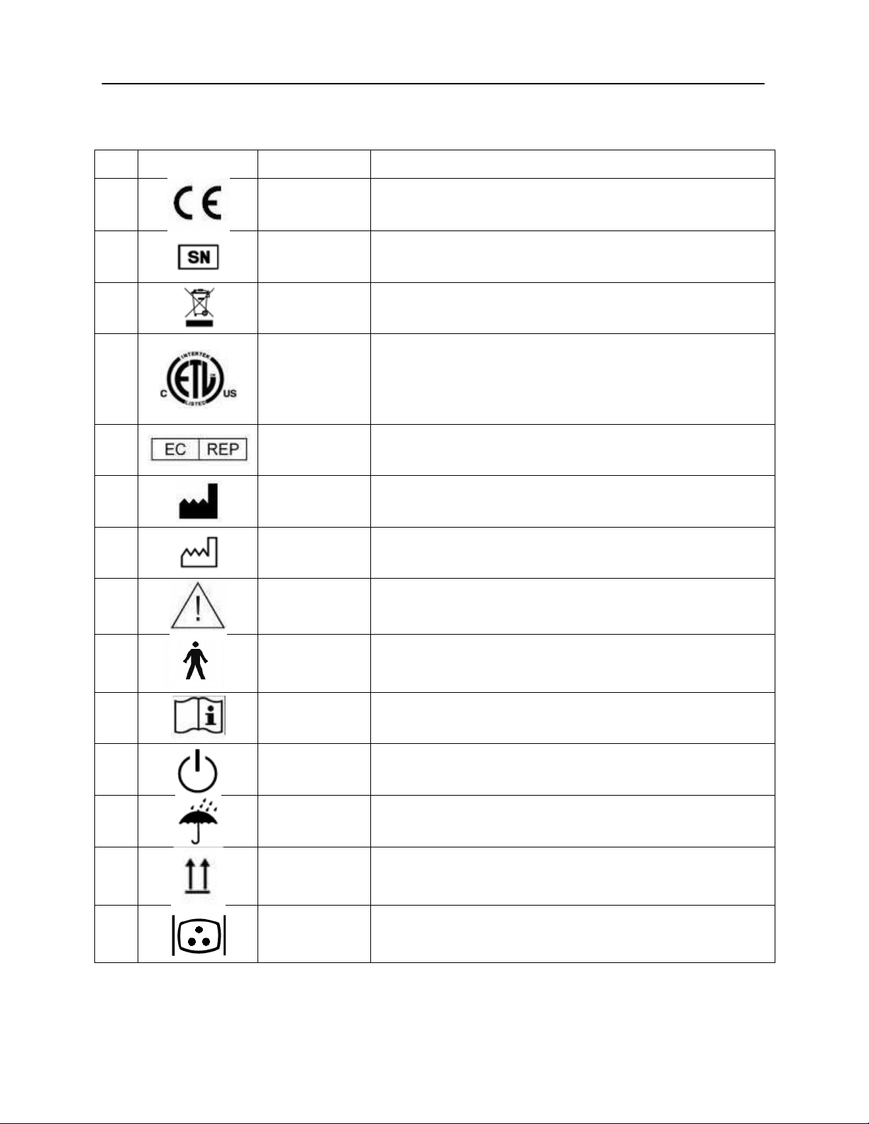
No.
Symbol
IEC Pub.
Description
1 980 & 60601-1
Conforms to European Medical Device Directive 93/94/EEC.
4 980 & 60601-1
Symbol for "SERIAL NUMBER."
6 980 & 60601-1
Return to Authorized Representative, Special disposal
required.
7 980 & 60601-1
Medical Equipment Classified by Intertek Testing Services
NA Inc. with respect to electric shock, fire, and mechanical
hazards only, in accordance with UL 60601-1. Classified
under the Medical Device Directive (93/42/EEC) as a Class
IIb device.
10 980 & 60601-1
Symbol for “European Representative.”
11 980 & 60601-1
Symbol for “Manufacturer.”
12 980 & 60601-1
Symbol for “Date of Manufacture.”
13 980 & 60601-1
Attention, consult accompanying documents.
14 60601-1
BF Patient Applied Part according to IEC 60601-1.
15 980 & 60601-1
Consult Operating Instructions.
16 60601-1
On/Off - Next to power mains.
17 60601-1
Keep Dry.
20 60601-1
This side up.
21 60601-1
Monitor.
Regulatory Symbols
D-0100778 Rev C 17
Page 19

GSI AudioStar Pro™ Clinical Audiometer
No.
Symbol
IEC Pub.
Description
22 60601-1
Patient response switch.
23 ISO 7010-M002
Follow Instructions for Use.
18 D-0100778 Rev C
Page 20

Audiometric Symbols
The AudioStar Pro can support different symbol sets to accommodate the
conventions in different countries. The country symbol sets that are supported
include:
Australia
China
Hong Kong
UK
USA
The AudioStar Pro Config App allows the selection of the desired symbol set.
The symbol sets are shown in the following table. For symbols that are not
specified in the reference documents for specific countries, the USA symbols are
used.
Abbreviations used in the following symbol set table
AC: Air Conduction
NR: No Response
BC: Bone Conduction
SF: Sound Field
MCL: Most Comfortable Level
UCL: Uncomfortable Level
D-0100778 Rev C 19
Page 21

GSI AudioStar Pro™ Clinical Audiometer
USA
Australia
China
Hong Kong
UK
R L L/R R L
L/R R L
L/R R L
L/R R L
L/R
AC
or
or
(NR)
or
or
AC
masked
(NR)
BC
(NR)
BC
masked
(NR)
BC
Forehead
(NR)
BC
Forehead
masked
(NR)
SF
(NR)
SF
masked
(NR)
SF Aided
(NR)
SF
Cochlear
(NR)
MCL
(NR)
UCL
(NR)
Tinnitus
(NR)
TEN
(NR)
AudioStar Pro Symbol Sets
20 D-0100778 Rev C
Page 22

Chapter 1: Introduction
The GSI AudioStar Pro™ continues the tradition of excellence in clinical
audiometry by maintaining the Grason-Stadler legacy of fast, efficient, and
familiar navigation. The one-button, one-function front panel of the AudioStar
Pro is recognized worldwide as the Gold Standard of user-friendly design,
allowing audiologists to test with confidence. From the extra large display that
reduces eye strain, to the ergonomic housing that maximizes hand and wrist
comfort, and the light pipes around selected test buttons allowing concentrated
focus on the patient, the AudioStar Pro has every desired feature.
Audiologists appreciate the flexibility of a stand-alone audiometer that offers
seamless data transfer to a computer. In the event of a network failure or
computer lock-up, the examiner will not lose patient data or the ability to test.
The stand alone configuration is optimized with direct connection to a wireless
keyboard and mouse making it fast and easy to enter patient demographics,
report comments, and expedite test administration. In addition, direct connection
to a printer and the integrated print button make it possible to print a complete
report for immediate review with the patient or physician. User login and
password controls provide security for patient data in compliance with HIPAA.
Complete audiometric results may be transferred to software such as GSI Suite
and Noah, or integrated with your facility’s EMR/EHR system.
The AudioStar Pro addresses the needs of a broad patient population. This
revolutionary audiometer introduces complete flexibility in signal routing by
enabling the user to select either Channel 1 or Channel 2 as the recorded stimulus
channel. The active microphone during tone presentation ensures there are no
delays in reinforcing or coaching. The built-in auxiliary intercom allows direct
communication between operator and assistant which eliminates the need for an
external intercom system. The built-in monitor speaker allows third parties to
participate in the patient evaluation. The built-in VRA controls facilitate fast and
simple activation of VRA systems eliminating the need for an external control
box. The pediatric centered signal options including pediatric noise provide
unique, frequency specific stimuli for pediatric testing. The built-in sound field
amplifier provides testing to 90 dB HL without the expense or space required for
an external amplifier. High performance speakers and a high performance
external amplifier are additional options for achieving 96 dB HL and 102 dB HL
outputs in the sound field environment. The built-in selection of Special Tests
including QuickSIN, BKB-SIN and TEN HL address special hearing evaluations.
The direct calibration for all the transducers allows seamless transition between
AC transducers without the need to plug and unplug saving time and eliminating
the need for correction factors.
The AudioStar Pro comes standard with integrated word lists for repeatable and
reliable recorded speech testing. Auto-advance, auto-play, auto-scoring and
mouse control allows the examiner to present, pause, repeat, skip, and score with
ultimate ease, removing the main objection for recorded speech testing. Other
speech-in-noise tests and word lists can be loaded directly from a flash drive.
Eight Test Type buttons allow access to protocols that are customized to facility
preferences. Tests are pre-programmed to optimize efficiency and workflow.
D-0100778 Rev C 21
Page 23

GSI AudioStar Pro™ Clinical Audiometer
NOTE: Refer to the supplied accessories list below to ensure that all accessories
and cables have been included in the shipment.
Chapter 2: Installation
External Inspection
Although this GSI AudioStar Pro Clinical Audiometer was carefully tested,
inspected, and packed for shipping, it is good practice after receiving the
instrument to immediately examine the outside of the container for any signs of
damage. Notify the carrier if any damage is observed.
Unpacking
Carefully remove the GSI AudioStar Pro from its shipping container. If the
instrument appears to have suffered any damage, notify the carrier immediately
so that a proper claim can be made. Be certain to save all packing material so that
the claim adjuster can inspect it as well. As soon as the carrier has completed the
inspection, notify a Grason-Stadler representative.
If the instrument must be returned to the factory, repack it carefully in the
original container, (if possible) and return it prepaid to the factory for the
necessary adjustments.
Check that all accessories are received in good condition. If any accessories are
missing, a Grason-Stadler representative should be notified immediately.
22 D-0100778 Rev C
Page 24
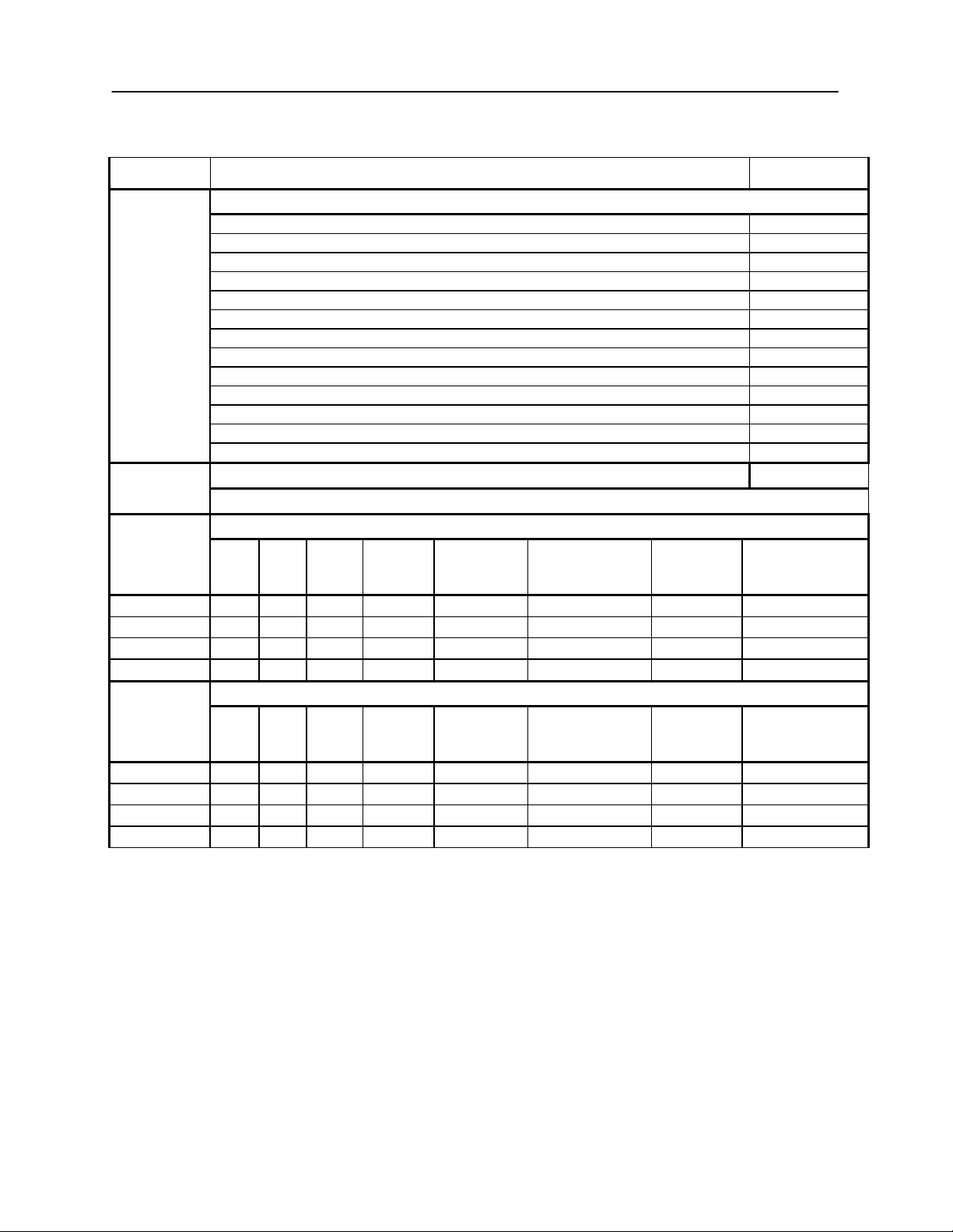
Product Descriptions
Part Number
AudioStar Pro™ Clinical Two-Channel Audiometer
Subject Response Hand switch
8004365
Headset, Operator/Monitor
8030462
Headphones, Assistant (Aux Intercom)
8030463
Extension cable - Assistant headphones, 3.5 meters
8121801
Talk Back Microphone with mounting bracket
8101853
Instruction Manual (AudioStar Pro™), English, paper
8030496
Quick Guide, English, paper
8100770
GSI Suite - Audiometric Data Management
8013063
Cable, USB A/B, 2 meters
8122259
CD, Applications (Config App)
8101169
CD, User manuals & Quick Guides
8101156
Calibration Certificate
8122375
Dust Cover
8013226
Country Kit, USA hospital grade power
8100120
Consists of: power cord and wireless mouse and keyboard
AudioStar Pro with Internal Display
Part
Number
TDH
50
B71
EAR
3A
HDA
200
Red
Patch
Cord
Blue Patch
Cord
Grey
Patch
Cord
Black Patch
Cord
8100230
√ √ 1 ea.
1 ea.
1 ea.
1 ea.
8100107
√ √ √ √ 3 ea.
3 ea.
1 ea.
1 ea.
8100671
√ √ √ 2 ea.
2 ea.
1 ea.
1 ea.
8101369
√ √ √ 2 ea.
2 ea.
1 ea.
1 ea.
AudioStar Pro without Internal Display
TDH
50
B71
EAR
3A
HDA
200
Red Patch
Cord
Blue Patch
Cord
Grey
Patch
Cord
Black Patch
Cord
8102055
√ √ 1 ea.
1 ea.
1 ea.
1 ea.
8121622
√ √ √ √ 3 ea.
3 ea.
1 ea.
1 ea.
8121624
√ √ √ 2 ea.
2 ea.
1 ea.
1 ea.
8121626
√ √ √ 2 ea.
2 ea.
1 ea.
1 ea.
Accessories
NOTE: Part numbers may change periodically. Please see the current GSI price/parts list for current part
numbers.
D-0100778 Rev C 23
Page 25

GSI AudioStar Pro™ Clinical Audiometer
Part Number
Country Description
8100120
United States Power Cord, English
8120249
United States Power Cord, Spanish
8120250
United States Power Cord, Portuguese
8120251
United States Power Cord, French
8100623
European Power Cord, French
8120252
European Power Cord, German
8100624
European Power Cord, Spanish
8120253
European Power Cord, Portuguese
8102218
European Power Cord, Russian
8100448
European Power Cord, English
8100672
United Kingdom Power Cord, English
8120254
Italian Power Cord, Italian
8120255
Italian Power Cord, Spanish
8120256
Swiss Power Cord, German
8120257
Swiss Power Cord, French
8120258
Swiss Power Cord, English
8120259
Danish Power Cord, English
8102037
Israel Power Cord, English
8100625
South African Power Cord, English
8100449
Australian Power Cord, English
8101076
Chinese Power Cord, Chinese
8102713
European Power Cord, Korean
8120260
United States Power Cord, Japanese
8120261
Brazilian Power Cord, Portuguese
Country Kits
GSI Country Kits include a power cord specific to a region of the world and a
user manual in the language for the specific country.
24 D-0100778 Rev C
Page 26
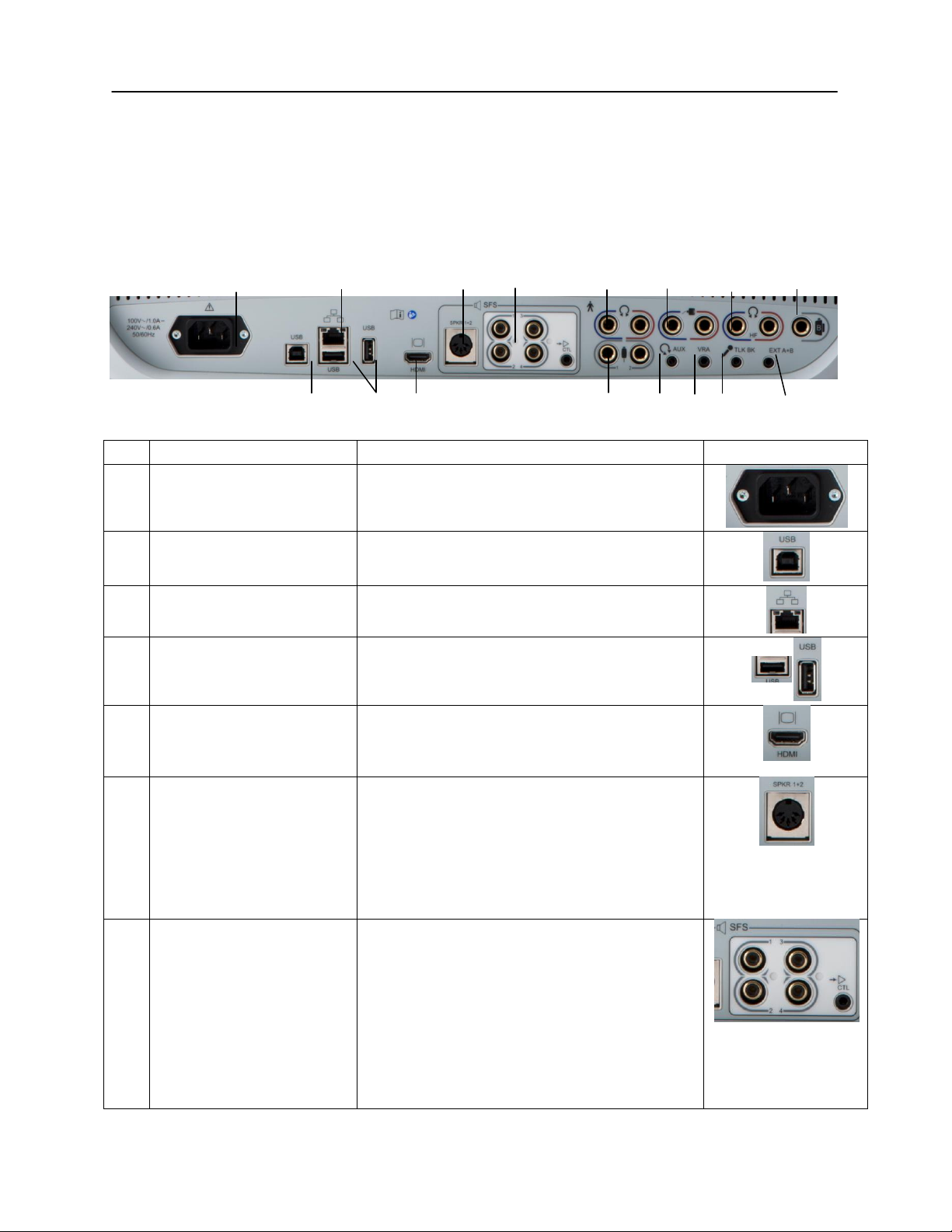
Connection
Description
Graphic
R1
Mains Power Input
IEC 14
R2
USB Computer
Connection
USB B style connector
R3
LAN Connections
Ethernet Connection RJ45
Currently not supported
R4
USB Connectors
USB A style plug
R5
External Monitor Output
HDMI
Video only signals, no audio, 600 x 800
resolution
R6
FF Speaker DIN
Connection Output
SFS - Sound Field Speaker
5 pin DIN connector
Provides connection between the internal
amplifier to left and right loudspeakers within a
sound room
NOTE:
Free Field Speaker Outputs 1 and 2 are
25 Watts per channel into 8 ohm.
R7
R7
FF Speaker RCA
Connections Output
FF Speaker RCA
4 RCA jacks
Optionally connect to 4 speakers through an
external amplifier using jacks 1 -4 (contact a
GSI Representative for more information)
NOTE:
Free Field Line Outputs 1 and 2 are 5
VRMS into a 2000 ohm load.
NOTE:
Cannot use internally amplified
Chapter 3: Connectors, Controls and Indicators
Rear Panel
The connectors on the rear panel of the GSI AudioStar Pro are shown in the
following diagram. The label and jacks are visible by turning the instrument
around on a flat, stable surface.
R1 R3 R6 R7 R8 R11 R13 R16
R2 R4 R5 R9 R10 R12 R14 R15
D-0100778 Rev C 25
Page 27
GSI AudioStar Pro™ Clinical Audiometer
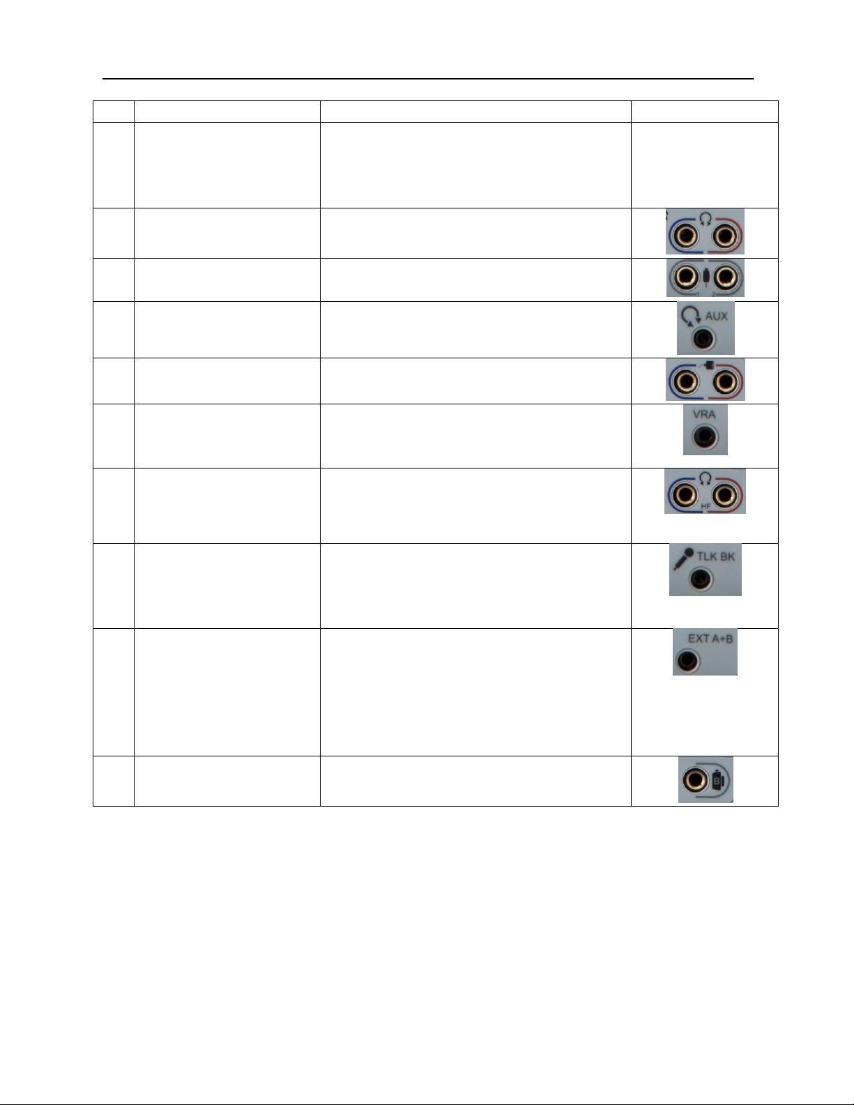
Connection
Description
Graphic
Connections Output,
cont.
speaker connection and externally amplified
speaker connections at the same time.
NOTE:
The CTL connection is for future use –
not currently supported.
R8
Left and Right
Headphone Outputs
6.35 mm stereo jack
Left (blue) and Right (red)
R9
Patient Response Inputs
6.35 mm mono jack
1 or 2 handswitches may be used
R10
AUX Intercom Output
3.5mm stereo jack
Assistant monitor headset connector
R11
Left and Right Insert
phone Outputs
6.35 mm stereo jack
Left (blue) and Right (red)
R12
VRA Connection Output
3.5 mm stereo jack to activate a left or right
VRA system (contact a GSI service
representative for details)
R13
Left and Right High
Frequency Headset
Output
6.35 mm stereo jack
Left (blue) and Right (red)
R14
Talkback Microphone
Input
3.5 mm stereo jack
NOTE:
Microphone inputs are between .25 mV
and 5 mV for a 0 dB reading on a VU indicator;
the input impedance is 3,200 ohm.
R15
Ext. A and B
3.5 mm stereo jack
Input jacks for optional digital music player or
CD player input
NOTE:
External A and B inputs are between
15 mV and 500 mV for a 0 dB reading on a VU
indicator; the input impedance is 50,000 ohm.
R16
Bone Vibrator
6.35 mm phone stereo jack
26 D-0100778 Rev C
Page 28
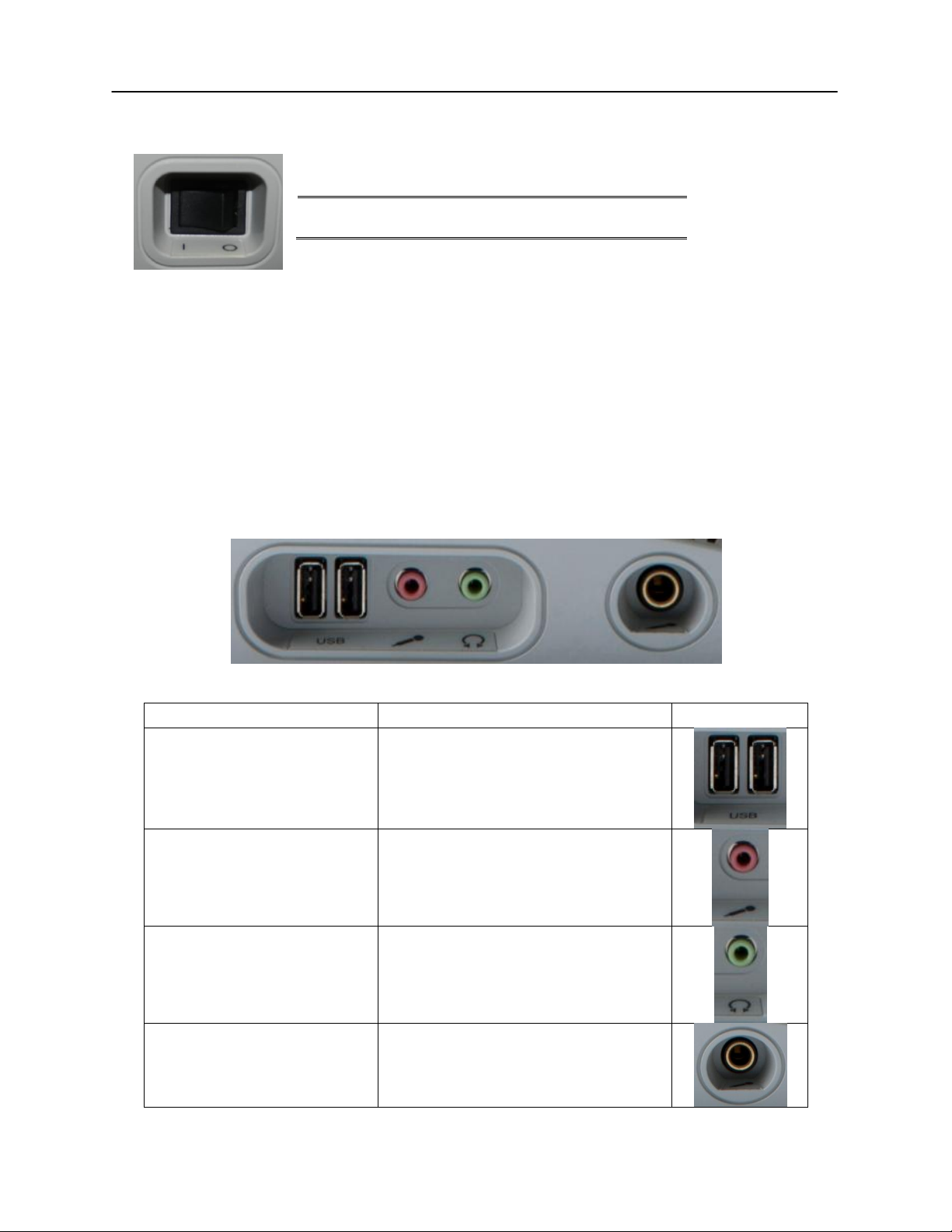
NOTE: Do not block access to the power switch.
Connection
Description
Graphic
USB Ports
2 USB ports (A style)
Monitor Headset
3.5 mm stereo jack
Monitor microphone
Headphones
3.5 mm stereo jack
Monitor speaker
Gooseneck Microphone
6.35 mm stereo jack (optional)
Right Side Panel
Monitor Speaker
Left Side Panel
The power switch is located on the right side panel.
The monitor speaker is located on the right side panel. If there is not anything
plugged into the headset jack of the mic/monitor headset, the monitor speaker
will be active. The intensity of the Channel 1 and Channel 2 stimuli may be
adjusted using the monitor knob on the front panel of the instrument.
The following connectors will be visible on the left side panel of the GSI
AudioStar Pro:
D-0100778 Rev C 27
Page 29

GSI AudioStar Pro™ Clinical Audiometer
NOTE: Scan files on a USB drive for viruses prior to installing the drive into the
instrument.
NOTE: It is recommended to always have the USB ports enabled on the PC.
Disable the “suspend USB” option on the PC.
USB Port The AudioStar Pro is equipped with four (4) USB ports. It is possible to connect
external devices such as mouse, keyboard, or external printer to be used with the
audiometer. Additionally, a memory stick may be inserted into a USB port for
updating software, adding additional sound files, or exporting diagnostic log
files.
A/B Cable Remote connection to an external computer is achieved through the use of a
standard A/B USB cable.
28 D-0100778 Rev C
Page 30
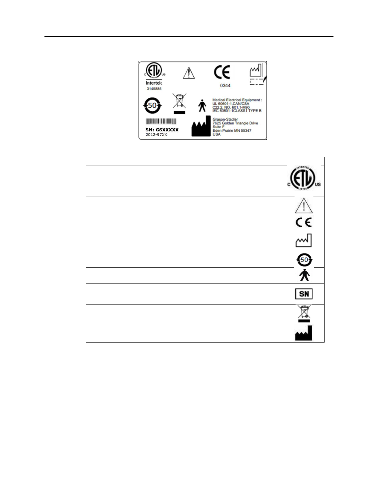
Description
Graphic
Medical Equipment Classified by Intertek Testing Services NA Inc.
with respect to electric shock, fire, and mechanical hazards only, in
accordance with UL 60601-1. Classified under the Medical Device
Directive (93/42/EEC) as a Class IIb device.
Caution, consult accompanying documents.
Conforms to European Medical Device Directive 93/94/EEC.
Manufacture Date (year will be inserted below).
China RoHS symbol for products with a 50 year life cycle.
B Patient Applied Part according to IEC 60601-1.
Serial Number and GSI Part Number.
Return to authorized representative, special disposal required.
Manufacturer.
Bottom Panel Label
D-0100778 Rev C 29
Page 31

GSI AudioStar Pro™ Clinical Audiometer
Chapter 4: Front Panel Controls
The controls on the front panel of the GSI AudioStar Pro are shown below.
Power
The green LED, located in the upper right portion of the front panel, is
illuminated when mains power is supplied to the GSI AudioStar Pro. This
indicates that the power switch is in the on position.
Stimulus Intensity Level(s)
Test Mic, Input A and Input B Level Controls — To calibrate the test signal
for the test microphone or the external devices, use the Select button to activate
the LED associated with the device. Then use the rotary knob to adjust the signal
intensity until an indication of 0 dB on average is obtained on the selected
channel VU meter.
30 D-0100778 Rev C
Page 32

Note: The talk forward mic may be calibrated using the mic level select
Talk Forward
This rotary control allows the operator to adjust the microphone intensity in a
continuous range of 45 to 90 dB HL when communicating through Talk Forward.
The Talk Forward Button allows the operator to speak directly to the patient
using the Mic/Monitor headset or optional gooseneck microphone. Pressing and
holding the Talk Forward button interrupts the stimulus that is being presented
and activates the microphone in all selected transducers on Channel 1 and
Channel 2. The GSI AudioStar Pro resumes the test status when the pushbutton is
released. The light pipe around the Talk Forward button will be illuminated when
enabled.
Left & Right VRA
When an external Visual Reinforcement Audiometry (VRA) remote box is
plugged into the VRA jack, and the Left or Right VRA button is pressed and
held, it will activate the VRA toy in the corresponding position. Pressing both
Right and Left VRA together will activate the Center position on compatible
VRA systems.
Interlock
The Interlock pushbutton locks the presentation function of the two channels
together so that stimulating one channel will also stimulate the other, according
to the status of the Interrupt button. When the Interlock is active, an icon is
displayed on the LCD and the light pipe around the button is illuminated.
Tracking
The Tracking pushbutton allows the Channel 2 hearing level to track the Channel
1 hearing level. When in Tracking, any dB change to the Channel 1 HL causes
the Channel 2 HL to change by the same amount, until the limit of the Channel 1
transducer is reached. If the dB HL limit is reached in Channel 2 before Channel
1, the Channel 2 dB HL display will temporarily flash and remain at this level.
Tracking remains on. When the Channel 1 dB returns to a level at which the
selected difference between the two channels can resume, Channel 2 again tracks
Channel 1. When tracking is selected, an icon will appear on the screen and the
light pipe will be illuminated. It is possible to manually change the intensity of
Channel 2 to alter the dB difference between the two channels without
deselecting Tracking.
D-0100778 Rev C 31
Page 33

GSI AudioStar Pro™ Clinical Audiometer
Status / Audiogram Button
The Status / Audiogram button is used to select the format for the screen display.
Pressing it will switch the screen between displaying the Status screen and the
Audiogram screen for the Tone, High Frequency, TEN and Speech Test Types.
On the Tone and High Frequency test types, this button allows access to the Fine
Frequency Resolution option for detailed frequency testing.
Data Transfer
When the Data Transfer button is pressed, a data record containing the stored test
data is transmitted to an external computer. Data is transferred as a complete
battery of all saved test results. The data transfer format is configurable – see
details regarding the data format options in the GSI Instrument Services manual.
Printing
If the appropriate printer is connected to the AudioStar Pro and the printer has
been configured properly using the Configuration Application Software, the
current stored test information is sent directly to the printer when the Print
pushbutton is pressed.
An HP color printer may be attached to the GSI AudioStar Pro to allow printing
of the audiometric test results directly from the AudioStar Pro. The HP Printer
must be PCL 5E, PCL 3, or PCL 3 GUI compatible.
Instrument Operation While Printing
The GSI AudioStar Pro remains operational while printing with the following
exceptions: pressing the Data Erase, Store or Data Transfer pushbuttons while
printing will result in the error message Please try another selection.
Print Messages
Printing A status bar will indicate the printing progress after the print button has
been pressed.
Check Printer Connection and Paper If there is an error detected during
printing, it is also recommended that the printer protocol in the configuration
application is verified.
32 D-0100778 Rev C
Page 34

Printer Output Formats
The printout formats are shown in the following figures.
D-0100778 Rev C 33
Page 35

GSI AudioStar Pro™ Clinical Audiometer
34 D-0100778 Rev C
Page 36

NOTE: The selection of Tone on Channel 1 and Mic on Channel 2 is a valid
combination. This setting allows the operator to have contact with the patient,
especially a young child, without the need to select Talk Forward.
NOTE: When using a digital music player, select the level using the
calibration track. First adjust the volume on the device until the VU meter
reads nearly 0 dB, then fine tune the intensity using the level selection.
Stimulus Channel 1 and Channel 2
Tone — The Tone pushbutton allows the selection of a pure tone stimulus for
air/bone conduction testing with the choice of five transducer types.
Mic — The Mic pushbutton provides input capability from the test microphone
for monitored live-voice testing with the choice of five transducer types.
Int./Ext. A, Int./Ext. B — Internal A and Internal B provide access to internal
.Wav files that may be used for recorded speech testing. External A and External
B accept recorded audiometric material from an optional digital music player or
compact disc player.
Narrow Band Noise — The NB Noise pushbutton selects a noise which is
geometrically centered at the selected test frequency and contains a 3 dB down
bandwidth of a 1/3 octave at a minimum and ½ octave at a maximum.
Speech Noise — The Speech Noise pushbutton selects speech noise that is
calibrated in effective masking level and contains a spectrum of equal energy per
frequency from 100 to 1,000 Hz with a 12 dB/octave roll-off from 1,000 to 6,000
Hz.
White Noise — The White pushbutton selects White Noise which is a broad
band signal containing acoustic energy at all frequencies between 125 Hz and
12,000 Hz. White noise is calibrated for pure tone effective masking if a tone
type signal is selected on the opposite channel and for speech effective masking
if a speech type signal is selected on the opposite channel.
D-0100778 Rev C 35
Page 37

GSI AudioStar Pro™ Clinical Audiometer
Channel 1 Stimulus
Tone
Mic
Ext. A
Ext. B
NB
Noise
S Noise
White
Noise
Channel 2
Stimulus
Tone
Valid
Valid
Valid
Valid
Valid
Invalid
Valid
Mic
Valid
Valid
Valid
Valid
Invalid
Valid
Valid
Ext. A
Valid
Valid
Valid
Valid
Invalid
Valid
Valid
Ext. B
Valid
Valid
Valid
Valid
Invalid
Valid
Valid
NBNoise
Valid
Invalid
Invalid
Invalid
Valid
Invalid
Invalid
S Noise
Invalid
Valid
Valid
Valid
Invalid
Valid
Invalid
W Noise*
Valid
Valid
Valid
Valid
Invalid
Invalid
Valid
NOTE: If White Noise is selected on both channels, then calibration is set to
speech effective masking levels. If White Noise is selected on one channel only,
calibration will be set to mask the stimulus type on the opposite channel.
Channel 1
Phone
Bone
Speaker
Insert
High
Freq.
Phones
Channel 2
Phone
Valid
Valid
Valid
Invalid
Invalid
Bone
Valid
Valid
Valid
Valid
Valid
Speaker
Valid
Valid
Valid
Valid
Valid
Insert
Invalid
Valid
Valid
Valid
Invalid
High Freq.
Phones
Invalid
Valid
Valid
Invalid
Valid
The selection of any stimulus will deselect a previously selected stimulus on the
opposite channel if the stimuli are not compatible. Refer to the following table
for the stimuli compatibilities listing:
Valid Stimuli Combinations
Transducer Output Selector
The Transducer pushbuttons allow the easy selection of the transducer for each
stimulus available for Channel 1 and Channel 2. A transducer selection may be
changed at anytime.
Valid Transducer Combinations
36 D-0100778 Rev C
Page 38

Note: When using four speakers a single channel can have a maximum of three
speakers. The total of all channels cannot exceed four
Routing Output
The Routing pushbuttons determine the routing for the stimulus to the output
transducer selected for Channel 1 and Channel 2. Left/Right delivers the stimuli
from the selected channel to both the left and right transducers with the combined
signal. Both the Channel 1 and Channel 2 maximum dB HL limits are
appropriately decreased from the non-mixed maximum dB HL limits.
The AudioStar Pro can support four speakers. Using a four speaker
configuration requires the instrument to be calibrated to accommodate all
speakers. Additionally, the speaker defaults and descriptions must be defined in
the Config App. When using four speakers a speaker routing dialog is displayed
when the Left/Right routing is selected and the transducer is speaker.
Attenuators (HL Controls)
Channel 1 and Channel 2
The GSI AudioStar Pro contains two independent HL rotary controls for test
signal and masking intensity level control with a range of -10 dB HL to 120 dB.
HL Maximum dB HL values apply to the mid-frequencies with earphones only.
Refer to the specific transducer for dB HL limits in the Table in Appendix 1.
D-0100778 Rev C 37
Page 39

GSI AudioStar Pro™ Clinical Audiometer
Present Bar / Interrupt
The function of the present bar in each channel is determined by the status of its
Interrupt button. When the interrupt button is in the off position, pressing the
present bar presents the stimulus to the selected transducer(s) for as long as the
present bar is depressed. The channel turns off immediately when the bar is
released. When the Interrupt button is in the on position, the corresponding
channel is deactivated by pressing the present bar and activated by releasing the
bar. Both the Interrupt buttons and present bars in each channel operate
independently of the other. Note that in the ABLB test mode, the Interrupt
pushbuttons do not operate independently of each other.
Frequency Up / Down
The Frequency pushbuttons allow the selection of twelve standard audiometric
frequencies and nine high frequencies with the High Frequency option. When at
the lower limit of the frequency selection, pressing the (<) pushbutton will cause
the display to roll over to the highest frequency limit, and vice versa. If a
transducer with a narrower range is selected, only the valid frequencies for that
transducer are available. The frequency order is configurable by using the
Configuration Application software.
Data Store
The Store pushbutton, when pressed, saves the current dB HL level representing
the current data point (threshold level, MCL, UCL, tinnitus,aided sound field,
cochlear implant and effective masking level if selected, as well as transducers
and routing. Pressing Store in the Speech testing mode will save the current test
type, word list, score and other applicable speech data. In the Display Audiogram
format, the appropriate symbol appears each time the Store button is pressed.
Navigation Controls
The four navigation buttons and the middle select button may be used to make
selections from the on-screen menus as well as navigate through the internal
.Wav files for speech testing.
38 D-0100778 Rev C
Page 40

NOTE: The timer may also be started by pressing the patient response button in
the Tone Decay test. The timer will be active as long as the patient response
button is depressed. When the patient response button is released, the timer will
be paused and may be resumed by pressing and holding the patient response
button again.
Icon
Description
Front
Panel
Configuratio
n
Examiner, Ch1 and Ch2 sounds can
be heard by the assistant
On
Checked
Ch1 and Ch2 sounds can be heard by
the assistant
Off
Checked
No sound goes the assistant monitor
headphones
On/Off
Unchecked
Scorer / Timer
The Correct, Clear and Incorrect pushbuttons are used for scoring results in
Speech, QuickSIN, BKB-SIN and SISI tests. The scorer is displayed in the test
status area of the Status screen. When Speech, QuickSIN, BKB-SIN or SISI is
selected, the scorer initializes to 0/0 = 0%. The operator presses the Correct or
Incorrect pushbutton after each presentation to score the evaluation. The display
clears with the pressing of the Clear pushbutton.
During Tone Decay tests, the Scorer/Timer pushbuttons may be used to start,
pause, stop and clear the timer. The timer is displayed in the test status area of the
Status screen. The timer may be set to stop at 1, 2, 3 or 4 minutes. The timer may
be paused and resumed at any point by pressing the Pause pushbutton. Pressing
Stop will stop the timer, but leave the current time displayed. Pressing Start will
reset the timer to 0:00 and restart the timer.
Aux Intercom
In Pure Tone testing, if the Incorrect/Stop button is pressed instead of the Store
button the No Response (NR) symbol is stored and displayed on the current
frequency and intensity on the audiogram.
When the AUX Intercom button is pressed, there may be direct communication
between the Operator and an Assistant. The assistant monitor headset allows the
assistant to monitor signals being delivered to the patient with the same settings
as the operator’s Microphone / Monitor headset. The Aux Intercom can be
configured as a toggle with the Configuration Application software. The button
may also be disabled from the Configure button on the device.
D-0100778 Rev C 39
Page 41

GSI AudioStar Pro™ Clinical Audiometer
Monitoring
Channel 1 (CH 1), Channel 2 (CH 2), AUX Intercom, Talkback Controls —
The Monitor Headset or Internal Speaker allows the operator to listen to the
stimuli as they are presented and to listen to the patient’s comments through the
talk-back system. The Assistant monitor headphones allow an assistant to listen
to the stimuli as they are presented and to listen to operator via the AUX
intercom. Adjust the Channel 1 (CH 1) and Channel 2 (CH 2) signals by using
the select button to choose the appropriate signal to be adjusted and then rotating
the knob to the desired intensity for the operator (and assistant). Select Talkback
to adjust the intensity of the patient’s voice for the operator. Select the AUX
Intercom to adjust the intensity of the operator’s voice for the Assistant
When Mic is selected, or when the Talk Forward is operated, that channel’s input
to the monitor speaker is disabled to reduce acoustic feedback.
Test Type Buttons
Test Type buttons allow the operator transition between audiometric evaluation
components with a single button press. Pressing a test type button loads all
stimuli, routing and transducer preferences from default settings or from
customized protocols determined in the Config App. Test types are preprogrammed to optimize efficiency and workflow.
40 D-0100778 Rev C
Page 42

Function Buttons
Examiner - This button displays a list of examiners that may be assigned to each
test session. Additional examiner names and security options are defined in the
configuration application.
Patient - This button displays a screen that allows the examiner to create a new
session, enter patient demographics, select a patient from the patient list, import a
patient list, transfer a session and delete a session.
Data Erase - This button erases user defined data from the internal memory. The
user may select to erase a single data point, the last curve or all session data.
Configure - From this screen, it is possible to view the instrument information
such as serial number, software version and the custom logo. This button displays
setup options to update the AudioStar Pro software, set the date and time,
configure bone conduction symbol settings, set the print format, enable/disable
the Aux Intercom and adjust the screen brightness.
Update - Place a USB drive with the appropriate update loaded into one
Date and Time - Select to change the date format and update the time
Bone - Select the symbol scheme for bone conduction testing. Choose
Print - Select to change the printing format for the current session. When
Aux Intercom - Select to turn off the Aux Intercom. When the box is
Brightness - Select to change the brightness of the screen.
of the four USB ports. Select Update and then select from device or
sound files to update the instrument. Software and Sound File updates
must be obtained from GSI or an authorized GSI representative.
displayed on the AudioStar Pro. It is necessary to use a keyboard to
update the date and time from the stand-alone instrument.
between Mastoid and Forehead. This selection will be active throughout
the current session. When a new session is started, the symbol scheme
will revert to the configured preference.
a new session is started, the print format will revert to the configured
preference.
checked the Aux Intercom is enabled. If the box is not checked the Aux
Intercom is disabled.
D-0100778 Rev C 41
Page 43

GSI AudioStar Pro™ Clinical Audiometer
Keyboard
Key
Instrument Function
B
Routing - Left/Right
F
Transducer - Speaker
H
Transducer – High Frequency Phone
I
Transducer - Insert
K
Interlock
L
Routing – Ch 1 Left Ch 2 Right
M
Masking
N
Tone No Response
P
Transducer - Phone
R
Routing – Ch 1 Right Ch 2 Left
S
Store
T
Tracking
V
Transducer - Bone
Space Bar
Ch 1 Present
Up Arrow
Ch 1 Increase Intensity
Down Arrow
Ch 1 Decrease Intensity
Right Arrow
Ch 1 Increase Frequency
Left Arrow
Ch 1 Decrease Frequency
Page Up
Ch 2 Increase Intensity
Page Down
Ch 2 Decrease Intensity
+ or =
Correct/Start
-
Incorrect/Stop
NOTE: channel 1 is always the stimulus and channel 2 is always masking when
using remote functionality
Keyboard
The AudioStar Pro works with a keyboard and many of the operations of the
front panel keys on the instrument may be performed using the keyboard. The
following table shows the mapping of the keyboard keys to the instrument.
42 D-0100778 Rev C
Page 44

NOTE: Recommended specifications for external monitor are as follows: HDMI
high definition monitor, 21.5 inch screen that supports 800 x 600 resolution in
order to maintain the aspect ratio of the audiogram.
NOTE: The time does not change automatically for daylight savings time. The
operator must manually change the time using the configure button on the front
panel of the instrument or the configuration application.
Chapter 5: Test Type Displays
Monitor
The AudioStar Pro comes standard with an LCD display. The LCD is hinged to
the GSI AudioStar Pro and is used to display all of the testing information from
the instrument. When the LCD is in the lowered position, easy access to the rear
connector panel is provided. It is possible to order the AudioStar Pro without the
LCD display and connect it to an external HDMI compatible monitor.
Test Type Screens
The information displayed on the AudioStar Pro LCD varies depending on the
Test Type. There are common elements found on all screens such as the Channel
1 and 2 intensity settings, the Navigation menu and the Title Bar.
Title Bar
The title bar is located at the top of the display. The title bar displays the test type
in the middle. The patient name will appear on the left side of the title bar if a
patient name has been entered (or selected from an imported patient list). The
right side of the title bar displays the examiner name if examiners have been
entered. The examiners can be entered from the Configuration application.
Test Type Information
Under the title bar test specific information will be displayed. On the left and
right side, the current output in dB HL for Channel 1 and Channel 2 will be
displayed. The other information displayed will depend on the test type and is
described as part of the individual test type displays.
Navigation Menu
This menu is located at the bottom of the display. It utilizes the on-board
navigation buttons or an external mouse to access the menu options. The menu is
specific to the test type selected.
Time and Date
The date and time are displayed in the bottom right corner of the screen. Using
the Configuration Application, the Time can be configured in a 12 or 24 hour
format and the Date can be configured in any order (dd/mm/yyyy, etc.). It is also
possible to set the format on the configuration screen of the instrument. It is
necessary to use an external keyboard to change the date and time from the
configure screen of the instrument.
D-0100778 Rev C 43
Page 45

GSI AudioStar Pro™ Clinical Audiometer
BVRA
Common Icons
These icons are found in the test information area and common to the different
test types
Talk Forward – When pressed, a head with a headset icon will appear. This icon
will remain active as long as the talk forward button is depressed.
Store – When either of the store buttons is pressed, a floppy disc icon flashes and
the result is then displayed.
Interlock – When interlock is active, a padlock icon will appear.
Tracking – When tracking is selected, a railroad track icon will appear.
Aux Intercom – When pressed, the Aux intercom icon indicates direct
communication between the operator and the Aux headset.
Data Transfer – When there is an active connection between the AudioStar Pro
and an external computer, communication will be indicated by the blue arrows.
Left and Right VRA – A two-toy VRA system may be connected to the
AudioStar Pro. The LVRA and RVRA icons will appear on the display when the
front panel buttons have been pressed to activate the VRA system. Pressing both
buttons will send the signal to the center toy in GSI compatible VRA systems.
Pressing both buttons will display a BVRA icon.
Pencil Icon
This icon opens a comments window (must use external keyboard to utilize
comment section). Comments may be entered from any test screen and it is
possible to review and edit comments from any test screen.
44 D-0100778 Rev C
Page 46

Tone Test Type - Audiogram
Tone Test - Audiogram Display
Title Bar
On the left side of the title bar, the patient name, if entered, will be displayed. In
the center of the title bar, the test type (Pure Tone) will be displayed. On the right
side of the title bar, the examiner name will be displayed. An underline on any
item on the display indicates that a choice may be made using the mouse. In the
title bar it is possible to select a patient, test type or examiner using the mouse to
display a drop down menu of the selection choices.
Channel 1 and Channel 2 Windows
The Channel 1 and 2 windows display the current output for each channel. The
sound wave symbol indicates that a stimulus is being presented. This sound wave
will be present as long as the present bar is depressed, will flash to indicate a
pulsed stimulus, and will be steady if “interrupt” is in the on position. The
intensity of the stimulus will be displayed in the color of the ear that has been
D-0100778 Rev C 45
Page 47

GSI AudioStar Pro™ Clinical Audiometer
selected for each channel. If Left/Right routing is selected, the Channel color will
be black. At extreme intensity levels, the intensity value will be highlighted in
yellow. When the attenuator has reached its upper limit (per transducer and
frequency), an NR label will be displayed (and highlighted in yellow if the
intensity is 100 dB or more), indicating No Response. The signal type (pulsed,
FM, pulsed/FM, steady), ear selected and transducer selected are displayed at the
bottom of the channel windows. The signal type, ear and transducer may be
selected with the mouse to display a drop down list of options for selection.
Frequency Window
This window will display the test frequency. When a patient response switch is
used, a bar will flash below the frequency when the patient depresses the button.
This bar will be gray if only one response switch is used. If two response
switches are used, then the bar will be blue for a left response and red for a right
response.
On Screen Data Logging
The Pure Tone Average (PTA) for air and bone conduction is automatically
calculated as the threshold data is collected. The frequencies used for the PTA
may be defined in the Configuration application.
The Speech Intelligibility Index (SII) is automatically calculated as the threshold
data is collected. The perception of speech information that is audible and usable
for each patient based on pure tone thresholds can be quickly calculated. There is
a high correlation between SII and word recognition scores.
Reliability may be reported as good, fair, or poor at any time throughout the
evaluation to indicate the validity of the results of the tests. None indicates that
the reliability was not labeled. Additional labels may be defined in the
configuration application. The reliability may be assigned by using the
navigation buttons in the comments window of the instrument. By clicking on the
reliability underline with the mouse a menu of reliability items defined by the
Configuration application will be displayed.
Audiogram View
Selecting the Audiogram viewing mode displays the audiometric data in graphic
format. The user may determine the layout of the audiogram graphs (Right/Left,
Left/Right, or combined into a single graph). Press and hold the Test Type Tone
button for two seconds to change the graph view.
Black crosshairs on the graph indicate position of the attenuator and oscillator.
The appropriate symbols will be displayed on the audiogram after either of the
Store buttons has been pressed. The effective masking levels for air conduction
and bone conduction will be displayed below the audiogram graphs.
46 D-0100778 Rev C
Page 48

NOTE: When HA or CI is selected the transducer will automatically change to
speakers as the selected transducer and FM as the signal type.
Navigation Menu
Signal Menu
Decibel (dB) Step
Threshold Test Type
Aided
The navigation menu contains the options for the Tone test type. The options
may be selected by using the navigation keys on the instrument or by using a
mouse. The right side of the menu displays the current date and time.
The signal menu displays a sub menu with the choices of signal type.
Steady – Indicates a steady pure tone or noise signal.
FM – Applies a frequency modulation (warble) to a pure tone stimulus.
Pulsed – Any signal or masking signal may be pulsed including narrow
band noise for a pediatric-focused stimulus.
FM/Pulsed – Applies both a warble and a pulse to the test signal
Ped Noise – Pediatric noise – a steeply filtered noise providing a
frequency specific signal and presented in HL
PN/Pulsed – Pulsed pediatric noise
Lock Menu – Locks the signal dialog box - the dialog box will remain on
the screen for efficient changing of signal types.
The dB Step button toggles the choices for the decibel steps. Each time this
option is selected with the navigation button or a mouse, the step size moves to
the next option. The options for dB step size are
1 dB
2 dB
5 dB
The Test Type button display a sub menu with the choices for the test type level.
HTL – Hearing Threshold Level. The appropriate threshold symbols will
be stored on the audiogram when HTL is selected.
MCL – Most Comfortable Level. An “M” symbol will be displayed.
UCL – Uncomfortable Level. A “U” symbol will be displayed.
Tinn – Tinnitus level. A “t” symbol will be displayed.
The Aided menu has 3 options that toggle each time the button is selected.
Blank
Aided (HA)
Cochlear Implant (CI)
When the box is HA or CI, the aided or cochlear implant symbol will appear on
the audiogram.
D-0100778 Rev C 47
Page 49

GSI AudioStar Pro™ Clinical Audiometer
NOTE: Only the frequencies appropriate for the test type are presented. If a
high frequency is included in the frequency list and the test type is standard, only
the standard frequencies are presented.
Auto Hz
The Auto Hz button controls whether or not the frequency automatically
advances to the next frequency to be tested when the store button is pressed. The
frequency presentation order is defined in the Configuration application. When
the Auto Hz option is checked, each time a threshold is stored (pressing Store)
the frequency will advance to the next test frequency automatically. If the option
is not checked, the frequency must be changed using the frequency buttons on the
front panel of the instrument.
Comments
This pencil icon opens a comments window (must use external keyboard to
utilize comment section). Comments may be entered from any test screen and it
is possible to review and edit comments from any test screen.
Stenger Test Results
In addition to entering comments, the dialog has the options for recording
Stenger test results (both pure tone and speech). The Stenger buttons on the
comments dialog may be toggled to indicate a positive or negative test result.
Off indicates that the test was not performed.
Reliability
The comments dialog also contains the option to record the patient test reliability.
Selecting the Reliability button from the comments dialog displays the options
for reliability. The options for the reliability label are defined in the
Configuration application.
48 D-0100778 Rev C
Page 50

High Frequency Test Type - Audiogram
The display for the High Frequency and the Tone tests are similar except for the
“range” option on the navigation menu. The High Frequency Range display does
not have the data calculations for the PTA or SII and only displays frequencies
from 8 kHz to 20 kHz.
The high frequency headphones (Sennheiser HDA 200/300) may be calibrated
from 125 Hz to 20 kHz. The display view may be configured as high frequencies
only from 8 kHz to 20 kHz or full frequency range from 125 Hz to 20 kHz. Use
the Range Selection button on the Navigation Menu to select the high frequency
range or the full frequency range.
High Frequency - Audiogram Display
D-0100778 Rev C 49
Page 51

GSI AudioStar Pro™ Clinical Audiometer
Full Frequency Test Type - Audiogram
The display for the Full Frequency and the Tone tests are identical except for the
“range” option on the navigation menu and the additional high frequencies
displayed in the audiogram.
The high frequency headphones (Sennheiser HDA 200/300) may be calibrated
from 125 Hz to 20 kHz. The display view may be configured as high frequencies
only from 8 kHz to 20 kHz or full frequency range from 125 Hz to 20 kHz. Use
the Range Selection button on the Navigation Menu to select the high frequency
range or the full frequency range.
Full Frequency Audiogram Display
50 D-0100778 Rev C
Page 52

Tone Test Type - Status
Tone Test Status Display
The Status display for the Tone Test Type presents the data in a tabular format.
The columns indicate the frequency, dB HL level and the effective masking level
(dB EM). The display contains the same elements as the audiogram display.
You may navigate the list of frequencies using the mouse or the frequency keys.
The Navigation Menu is similar to the audiogram Navigation Menu but has one
additional button – Fine Hz.
Fine Frequency Resolution
The Fine Hz button allows the user to select from a sub menu of different octave
band frequency resolutions and single hertz resolution. When an octave band or
single hertz resolution is selected the table is updated with the available
frequencies. Navigation keys on the right and left of the table provide ‘page’
movement in the list. If the resolution is 1 Hz then there are additional
movement icons that move the table in 1000 Hz increments.
D-0100778 Rev C 51
Page 53

GSI AudioStar Pro™ Clinical Audiometer
Tone Test Status Display – Single Hz Resolution
The right and left outlined areas show the list navigation icons. The top (darker
icon) moves +/- 1000 Hz and the other arrow moves to the next/previous page.
High Frequency Test Type – Status
Full Frequency Test Type - Status
The display for the High Frequency and Full Frequency Status and the Tone Test
Status are identical except for the “range” option on the Navigation Menu. Use
the Range Selection button on the Navigation Menu to select the high frequency
range or the full frequency range.
52 D-0100778 Rev C
Page 54

Speech Test Type - Status
Speech Test Status Display
Title Bar
On the left side of the title bar, the patient name, if entered, will be displayed. In
the center of the title bar, the test type (Speech) will be displayed. On the right
side of the title bar, the examiner name will be displayed. An underline on any
item on the display indicates that a choice may be made using the mouse. In the
title bar, it is possible to select a patient, test type or examiner using the mouse to
display a drop down menu of the selection choices.
D-0100778 Rev C 53
Page 55

GSI AudioStar Pro™ Clinical Audiometer
NOTE: When using internal .Wav files, the Correct, Incorrect and Clear
buttons are inactive while the stimulus is being presented.
Channel 1 and Channel 2 Windows
The sound wave icon and the VU meter indicate when a stimulus is being
presented. The sound wave icon and VU meter will remain active through the
duration of the stimulus.
The intensity of the stimulus will be displayed in the color of the ear that has
been selected for each channel (red for right, blue for left and black for binaural).
At extreme intensity levels, the intensity value will be highlighted in yellow.
When the attenuator has reached its upper limit (per transducer) the level will
flash and the NR symbol will appear.
The stimulus source (Microphone, INT/EXT A or INT/EXT B), ear selected, and
transducer selected are displayed at the bottom of the channel windows. The
signal type, ear and transducer may be selected with the mouse to display a drop
down list of choices for selection.
Scoring Window
This scoring window displays the speech scores in a percentage value. The scores
are populated using the Correct/Incorrect buttons on the front panel of the
instrument. The left side indicates the number of correct responses over the total
presented. The right side converts this into a percentage. The lower part
indicates the current word being presented.
On Screen Data Logging
Pure Tone Average (PTA) for air and bone conduction is automatically
populated from the tone test screen if the data is available. The audiologist may
quickly compare the results of the PTA with the results of the Speech Reception
Threshold (SRT) or Speech Detection Threshold (SDT) to rule out the possibility
of pseudohypoacousis.
Speech Intelligibility Index (SII) is automatically populated from the tone test
screen if the data is available. The audiologist may quickly quantify the speech
information that is audible to the patient and compare to the word recognition
score (WRS). There is a high correlation between SII and WRS.
Speech Test Results
The Speech Test Results Table displays the speech information for the tests that
have been stored. To store a speech test result the Store button is pressed on the
instrument. The results table stores the ear, test type speech source, the word list
presented, if an aid (hearing aid or cochlear implant) was used by the patient, the
percentage correct, the HL level and the masking level. There are two tables and
each table can hold up to 6 tests.
54 D-0100778 Rev C
Page 56

Words/Sentences for Presentation
Navigation Menu
Test Type
Word Lists
Word Nav
The lower part of the Speech display shows the words from the selected word
list. The words on the list may be presented by selecting the word with the
mouse or by using the navigation buttons on the device (and the Word Nav
option from the Navigation Menu) to highlight the word and pressing the present
button. When a word is being presented, the background of the selected word
will be highlighted in yellow. As the words are scored by pressing the correct or
incorrect button, the correct word cells are colored green and the incorrect word
cells are colored red. If more words are on the list than can be displayed,
additional pages are used. This is indicated in the top right area of the word list
title bar. There are up/down arrows that allow movement between pages using
the mouse. When the last word on the list is presented the next page will be
displayed. Using the navigation buttons on the instrument you can move to the
next page by pressing the down or right navigation key on the last word in the
list.
Select SRT (Speech Reception Threshold), SDT (Speech Detection Threshold),
WRS (Word Recognition Score), SRS (Speech/Sentence Recognition Score),
MCL (Most Comfortable Level) or UCL (Uncomfortable Level); this will
determine how the record is scored and labeled.
Using the on-board navigation keys or an external mouse, selecting this button
will pull up a menu of available word list options. The operator may select the
source (internal or external), the CD name (protocol of assorted word lists such
as Adult Basic Evaluation or Child Basic Evaluation) and the word list. When the
word list has been selected by pressing Save, the dialog box will disappear and
the words will appear in the bottom half of the display screen. There is a favorite
list at the top of the word list dialog. This favorite list is specific to the test type
and is set up in the Configuration application. The favorite list is automatically
populated when the test type is selected.
When selected, this option presents a sub menu of options. The Manual option
moves the cursor control to the word lists and allows the operator to use the
navigation buttons to scroll to specific words in the internal word lists. To return
D-0100778 Rev C 55
Page 57

GSI AudioStar Pro™ Clinical Audiometer
NOTE: In Manual mode, highlight the desired word and press the presentation
bar to present the word. When the word is presented, it will be highlighted
yellow. When the yellow highlight disappears, score the word and move to the
next test word using the navigation keys. If a score is indicated before the
highlight disappears it might not be accepted as a score.
NOTE: When scoring phonemes (CVC, etc), it is necessary to deselect the Auto
Advance option to ensure that three “scores” may be entered per word
NOTE: When HA or CI is selected the transducer will automatically change to
speakers as the selected transducer.
to the Navigation Menu, deselect Word Nav (by pressing the select key of the
navigation controls). The Auto Advance check box determines the word
movement behavior that is set up in the Configuration application. The Auto
Advance moves to the next word in the list after a score key (Correct/Incorrect) is
pressed. The Auto Play option has a box indicating the time (in seconds) and
up/down arrows to adjust the time. The Auto Play option will automatically
present the word and the time is how long between the word presentations. Auto
Play is activated by pressing the interrupt button. The Configuration application
defines the behavior of the Auto Play option. The auto play option may be
defined to do one of the following; wait for a score, score as correct, incorrect or
no score when the time expires.
Aided
Select this box to indicate if the word list was presented in an aided condition.
The Aided menu has 3 options that toggle each time the button is selected.
Decibel (dB) Step
The dB Step button toggles the choices for the decibel steps. Each time this
option is selected with the navigation button or a mouse, the step size moves to
the next option. The options for dB step size are
Display PT Audiogram
The audiogram checkbox displays the pure tone air conduction audiogram in
place of half of the Speech test Results table. This button acts as a toggle to
display the audiogram or speech results table. The audiogram that is displayed is
for the ear being tested.
Blank
Aided (HA)
Cochlear Implant (CI)
1 dB
2 dB
5 dB
56 D-0100778 Rev C
Page 58

Speech Test Status Display – Pure Tone AC Audiogram
Comments
This pencil icon opens a comments window (must use external keyboard to
utilize comment section). Comments may be entered from any test screen and it
is possible to review and edit comments from any test screen.
Stenger Test Results
In addition to entering comments, the dialog has the options for recording
Stenger test results (both pure tone and speech). The Stenger buttons on the
comments dialog may be toggled to indicate a positive or negative test result.
Off indicates that the test was not performed.
Reliability
The comments dialog also contains the option to record the patient test reliability.
Selecting the Reliability button from the comments dialog displays the options
for reliability. The options for the reliability label are defined in the
Configuration application.
D-0100778 Rev C 57
Page 59

GSI AudioStar Pro™ Clinical Audiometer
Speech Test Type - Audiogram
Speech Test Audiogram Display
This Speech Test Audiogram displays speech results in a graphic format and has
the Rollover Index Table. The display for the Speech Test Audiogram is identical
to the Speech Test Status display except for middle section of the display. The
Speech Test Results tables are replaced with the Speech Audiogram and Speech
Rollover Results Table. One new menu option, New Curve, is added to the
Navigation Menu.
The SRT score will be plotted on the Speech Audiogram at 50% on the
corresponding intensity. Word recognition scores will be plotted on the Speech
Audiogram based on the intensity at which the test was performed and the score
that was achieved. As additional WRS are plotted, the AudioStar Pro will
determine PIPB (Performance Intensity Function for Phonetically Balanced
Words) function. PIPB function is tested by comparing two (2) or more WRS
results performed at different intensities. It will automatically calculate and
display in the table the Rollover index when enough data is available.
58 D-0100778 Rev C
Page 60

NOTE: Only curves with PIPB Rollover will be displayed in the rollover results
table.
Navigation Menu
The Navigation menu has the same functionality and selections as the Speech
Status display and the addition of the New Curve menu item.
New Curve
The new curve button on the Navigation Menu starts a new curve on the speech
audiogram. The current data is maintained and you can start a new test collecting
SRT and WRS data that will be plotted on the graph and resulted displayed in the
Speech Rollover Results table.
D-0100778 Rev C 59
Page 61

GSI AudioStar Pro™ Clinical Audiometer
More Test Type
ABLB
In ABLB (Alternate Binaural Loudness Balance) test the tone is presented
alternately between the two ears. The level of the tone stays the same in one ear
(i.e. fixed ear) and is varied up / down in the other ear (i.e. variable ear).
The top section ABLB test display has common elements found on the
previously described screens. The Navigation Menu has a single option for the
dB Step in addition to the comment icon. The results should be stored as a
comment.
60 D-0100778 Rev C
Page 62

Note: In order to obtain a SNR loss the age range must be indicated in the Age
box of the Navigation Menu.
BKB-SIN
The BKB-SIN is a speech-in-noise test that uses BKB (Bamford-Kowal-Bench)
sentences, recorded in four-talker babble. The BKB-SIN can be used to estimate
SNR loss in children and adults for whom the QuickSIN test is too difficult.
The BKB-SIN display has the Title bar and the Channel 1 and 2 Output sections
that are similar to what has been described for the speech displays.
Scoring Window
There are two scoring windows in the middle of the top section of the display.
The scoring windows show the calculated average of the individual list test
scores. The scores are separated for the ear and group and reported as the SNR
loss. There can be two groups for comparison.
D-0100778 Rev C 61
Page 63

GSI AudioStar Pro™ Clinical Audiometer
BKB-SIN Test Results
The BKB-SIN Test Results Table displays the information for the tests that have
been stored. The data is separated by ear and group. The results include the
SNR 50 and the SNR Loss. For details on the scoring see the BKB-SIN manual.
The SNR Loss can only be calculated if the age range is indicated in the Age
button on the Navigation menu.
BKB-SIN Sentences and Score
The lower section of the display contains the BKB-SIN sentences. The
capitalized words indicate the target words to be scored. Next to the sentence is
the score box for the sentence with an indication of the Signal to Noise (S/N)
ratio for the sentence.
The sentence on the list may be chosen for presentation by selecting with the
mouse or by using the navigation buttons on the device (and the Word Nav
option from the Navigation Menu) to highlight the sentence and pressing the
present button. When a sentence is being presented the background will be
highlighted yellow. The sentences are scored by pressing the correct or incorrect
button, the appropriate number of times. If more sentences are on the list than
can be displayed, additional pages are used. This is indicated in the top right area
of the sentence list title bar. There are up/down arrows that allow movement
between pages using the mouse. When the last sentence on the list is presented
the next page will be displayed. Using the navigation buttons on the instrument,
move to the next page by pressing the down or right navigation key on the last
sentence in the list.
Navigation Menu
The Navigation Menu contains options that are the same as those previously
described for the speech displays. The Word List, Word Nav, Aided, dB Step
and the comment icon items function the same as in the Speech display. The
Navigation Menu also contains items unique to the BKB-SIN test.
Age
The age menu item is a toggle that provides a choice of age ranges for the
patient. This information is necessary to score the results and provide an SNR
loss calculation. The age range is automatically set if the patient date of birth has
62 D-0100778 Rev C
Page 64

Note: When using Split Track I both Channel 1 and 2 outputs should be set to the
same HL level. If the output HL is different for the channels then the S/N ratio
will not be correctly maintained.
Group
Research
been entered in the demographic information. If the date of birth has not been
entered, toggle the age button to choose the appropriate age range. The
selections correspond to the BKB-SIN test norms.
The Group menu item acts as a toggle to indicate the ‘group’ for the testing. In
the BKB-SIN test, up to 2 groups may be used to compare different conditions.
Such comparisons might be used to demonstrate the benefits of amplification
(unaided vs. aided) or assess directional microphone performance (no directional
mic vs. directional mic). The BKB-SIN Test is a flexible tool that may be
applied clinically in a variety of ways by adjusting the presentation level or the
presentation mode.
The Research menu item is a check box to indicate that the system is in Research
mode. Research mode is designed for research and special applications. In the
Research mode the Output for Channel 1 and 2 may be controlled independently.
In the ‘Standard’ mode the Output for Channel 2 cannot be adjusted. The Split
Track lists should be used for Research mode. The standard BKB-SIN sentences
have the target talker and background babble recorded on the same channel and
the S/N ratio integrated into the recording. The Split Track lists provide the
ability to control the signal and noise in ways not available in the standard
sentences.
Split Track I
In these recordings the target talker and background babble are recorded on
separate channels (Channel 1 = target talker, Channel 2 = background babble) so
the speech and babble may be presented through separate loudspeakers in the
sound field. When the audiometer attenuators are set correctly (both attenuators
set to identical presentation levels) these tracks maintain the same signal-to-noise
ratios as on the standard recording; that is, the signal-to-noise ratio automatically
changes by 3 dB for each sentence.
Split Track II
Both channels of these tracks (Channel 1 = target talker, Channel 2 = background
babble) were recorded at a constant overall level. The signal-to-noise ratios do
not change automatically after each sentence; the tester must manually adjust the
level of the target talker and/or the background babble to change the signal-tonoise ratio.
D-0100778 Rev C 63
Page 65

GSI AudioStar Pro™ Clinical Audiometer
QuickSIN
The QuickSIN is a speech-in-noise test that quickly and easily measures the
ability to understand speech in noise. The QuickSIN is comprised of sentences
recorded in four-talker babble.
The QuickSIN display has the Title bar and the Channel 1 and 2 Output sections
that are similar to what has been described for the speech displays.
Scoring Window
There are two scoring windows in the middle of the top section of the display.
The scoring windows display the calculated average of the individual list test
scores. The scores are separated for the ear, group, QuickSIN sentence type and
are reported as the SNR loss. There can be two groups so that comparisons may
be made.
64 D-0100778 Rev C
Page 66

QuickSIN Test Results
QuickSIN Sentences and Score
The QuickSIN Test Results Table displays the information for
the tests that have been stored. The data is separated by ear
and group. The results include the SNR 50 and the SNR Loss.
For details on the scoring see the QuickSIN manual.
Navigation Menu
The lower section of the display contains the QuickSIN sentences. The
capitalized words indicate the target words to be scored. Next to the sentence is
the score box for the sentence with an indication of the Signal to Noise (S/N)
ratio for the sentence.
The sentence on the list may be chosen for presentation by selecting with the
mouse or by using the navigation buttons on the device (and the Word Nav
option from the Navigation Menu) to highlight the sentence and pressing the
present button. When a sentence is being presented the background will be
highlighted yellow. The sentences are scored by pressing the correct or incorrect
button, the appropriate number of times. If more sentences are on the list than
can be displayed, additional pages are used. This is indicated in the top right area
of the sentence list title bar. There are up/down arrows that allow movement
between pages using the mouse. When the last sentence on the list is presented
the next page will be displayed. Using the navigation buttons on the instrument,
move to the next page by pressing the down or right navigation key on the last
sentence in the list.
The Navigation Menu contains options that are the same as those previously
described for the speech displays. The Word List, Word Nav, Aided, dB Step
and the comment icon items function the same as in the Speech display. The
Navigation Menu also contains items unique to the QuickSIN test.
D-0100778 Rev C 65
Page 67

GSI AudioStar Pro™ Clinical Audiometer
Group
The Group menu item acts as a toggle to indicate the ‘group’ for the testing. In
the QuickSIN test, up to 2 groups may be used to compare different conditions.
Such comparisons might be used to demonstrate the benefits of amplification
(unaided vs. aided) or assess directional microphone performance (no directional
mic vs. directional mic). The QuickSIN Test is a flexible tool that may be
applied clinically in a variety of ways by adjusting the presentation level or the
presentation mode.
Research
The Research menu item is a check box to indicate that the system is in Research
mode. Research mode is designed for research and special applications. In the
Research mode the Output for Channel 1 and 2 may be controlled independently.
In the ‘Standard’ mode the Output for Channel 2 cannot be adjusted. The
Separated Track lists should be used for Research mode. The standard QuickSIN
sentences have the target talker and background babble recorded on the same
channel and the S/N ratio integrated into the recording. The Separated Track lists
provide the ability to control the signal and noise in ways not available in the
standard sentences.
Separated Tracks
Both channels of these tracks (Channel 1 = target talker, Channel 2 = background
babble) were recorded at a constant overall level. The signal-to-noise ratios do
not change automatically after each sentence; the tester must manually adjust the
level of the target talker and/or the background babble to change the signal-tonoise ratio.
66 D-0100778 Rev C
Page 68

SISI
The SISI (Short Increment Sensitivity Index) test requires the generation of a
continuous tone that increases in intensity a selected amount at a selected point in
time. The SISI has intensity increments of 5 dB, 2 dB and 1 dB. An intensity
increment is added to a tone in the selected channel for 200 msec, every 5
seconds.
The top section of the display has the common elements found on all the
previously described screens. The center section displays the results of the
testing. Using the Correct/Incorrect score buttons, obtain a percentage correct of
the patient responses. The results are added to the table when the test is Stored.
The Navigation Menu has an option for the dB Step (continuous HL level) and an
option for the SISI step (intensity increment). The results are not transferred to
GSI Suite via the data transfer and therefore should be entered as a comment.
D-0100778 Rev C 67
Page 69

GSI AudioStar Pro™ Clinical Audiometer
TEN
The TEN test involves measuring the threshold for detecting a sinusoidal tone
presented in a special background noise called “threshold-equalising noise”
(TEN). The methods used to conduct the test are similar to those used for
masking in conventional pure-tone audiometry, except that the signal threshold is
measured in the presence of a continuous background noise and a 2-dB final step
size is used to measure thresholds. The test was designed for detecting the
presence of cochlear dead regions and defining their limits. The TEN Test
defaults to a pulsed tone and 2 dB Step size.
The TEN test display is similar to the tone test type audiogram display. The
Navigation Menu has a single option for the dB Step in addition to the comment
icon. The data is stored by pressing the Store button and when stored a TEN
symbol is displayed on the audiogram.
68 D-0100778 Rev C
Page 70

Tone Decay
The Tone Decay test evaluates auditory fatigue. The general procedure is to
measure the ability to perceive and maintain a pure tone presented continuously
(usually for 1 minute).
The top section of the display has the common elements found on the previously
described screens. The center section displays the timer. The timer is started
when the patient presses the response button or may be started manually from the
Correct/Start button on front panel. When the patient response button is released
it pauses the timer and when pressed again resumes. The Navigation Menu has
an option for the dB Step and an option to set the time in minutes (1-4). The time
setting in the Navigation Menu will stop the timer after the defined number of
minutes is reached on the timer. The results are not transferred to GSI Suite via
the data transfer and therefore should be entered as a comment.
D-0100778 Rev C 69
Page 71

GSI AudioStar Pro™ Clinical Audiometer
Chapter 6: Operation
Preliminary Checks
Before starting any procedures using the GSI AudioStar Pro Clinical
Audiometer, ensure that the power cord is plugged into a properly grounded
receptacle.
WARNING! Check also that all cords from the transducers, patient response
hand switch (if used), and printer fit securely in their connectors on the rear and
side panels.
Inspect all cords for fraying and damage. If there is any damage to any cord, do
not use the AudioStar Pro. If speech testing with recorded voice from an external
source is to be performed, check that the CD or digital music player device is
connected and operating properly.
1. Turn on the instrument and allow it to come to operating temperature
(approximately 10 minutes).
2. Check that the transducers and other system components are operating
properly.
3. Seat the patient comfortably in the test area.
4. Place the selected transducers on the patient.
CAUTION! Handle earphones, bone vibrator, and insert earphones with care.
Do not drop them nor allow them to be banged together. Severe mechanical
shock can alter their operating characteristics or change the output levels, which
may require that the transducers be replaced.
CAUTION! It is recommended that all parts that come into direct contact with
the patient (e.g. earphone cushions) are subjected to standard disinfecting
procedures between patients. This includes physically cleaning and using a
recognized disinfectant. Individual manufacturer’s instructions should be
followed for use of any disinfecting agent to provide an appropriate level of
sterilization.
Placement of the Earphones
Prior to positioning the earphones on the patient’s head, inspect the ear canals for
any blockage due to cerumen or foreign objects. Recognize that soft-walled ear
canals may collapse under the earphones and this may lead to incorrect threshold
levels. Insert phones might be used in these cases. Eliminate all obstructions,
such as glasses, hair, or hearing aid, between the earphone and the patient.
Center the earphone over both ears and adjust the headband so that it rests solidly
on the crown of the head and exerts pressure on both ears. Place the earphone
with the red connector over the patient’s right ear and the earphone with the blue
connector over the left ear.
Placement of the Insert Phone
WARNING! Push the correctly sized eartip onto the earphone and then place the
insert phone securely into the patient’s ear. Be sure there is an eartip attached to
70 D-0100778 Rev C
Page 72

NOTE: Press “Store” after each threshold is obtained
the insert phone before inserting into the patient’s ear. Inserting the insert phone
without an eartip could cause harm to the patient. When using the paired insert
phones, follow the manufacturer’s recommended procedure for eartip
preparation, placement, and insertion.
WARNING! Insert eartips are single use only. Using disposable eartips ensures
sanitary conditions for each patient.
Placement of the Bone Vibrator
The bone vibrator may be placed on the promontory of the mastoid process or on
the forehead, whichever has been selected in the configuration application or
modified in the Configure screen.
Placement of the High Frequency Transducer
Remove eyeglasses and earrings if possible and position the transducer directly
on the head of the patient. Place the rubber cushions so that the earphone
diaphragm is aimed directly at the opening into the ear canal. Adjust the
headband for a tight fit. If the cushions are not tight to the ears, the test result will
be false, especially at lower frequencies.
WARNING! Do not connect or disconnect Earphones, Insert Phones, Bone
Vibrator, High Frequency Transducers or any other accessories while in contact
with the patient.
Typical Evaluations
Test Type Buttons
Test Type buttons allow the operator to access protocols that are customized to
facility preference with a single button press. Tests are pre-programmed to
optimize efficiency and workflow. The options for the defaults for each test type
are set up in the Configuration application.
Tone Test Type Button
Pressing the Tone Test Type button prepares the AudioStar Pro for pure tone air
and bone conduction testing from 125 to 12,000 Hz. Each selection on the blue
Navigation Menu is specific to Pure Tone Testing. It is possible to utilize
headphones (TDH 50, DD45) insert earphones (ER3A, IP30) bone vibrators
(B71, B81) and Sound Field speakers from this test type. Pressing this button will
set the defaults from the configuration application to start the test.
Press the Tone Test Type Button.
Verify that the transducers and signals are correct.
Perform air conduction threshold testing.
When the pure tone evaluation is complete, move to the next test type in
the typical testing sequence.
D-0100778 Rev C 71
Page 73

GSI AudioStar Pro™ Clinical Audiometer
NOTE: Press “Store” after each threshold is obtained.
High Hz Test Type Button
Pressing the High Hz test type button prepares the AudioStar Pro for high
frequency air and bone conduction testing from the high range (8,000 to 20,000
Hz) or the full range (125 to 20,000 Hz). Select full or high range from the blue
navigation menu. It is possible to utilize the high frequency headphones (HDA
200/300), bone vibrator (B71, B81) and sound field speakers from this test type.
Pressing this button will set the defaults from the configuration application to
start the test.
Press the High Hz Test Type Button.
Ensure that the Range is set to user preferences (High or Full).
Verify that the transducers and signals are correct.
Perform High Frequency Testing.
When the high frequency evaluation is complete, move to the next test
type in the typical testing sequence.
Speech Test Type Button
Pressing the Speech Test type button prepares the AudioStar Pro for Speech
testing. The internal .Wav files may be presented by either using the auto play
options, the present button or by a single click of a wireless mouse. The
correct/incorrect/clear buttons may be used to score. It is critical that the test type
be carefully selected as the reporting/storing is dependent upon test type. To
perform a PIPB rollover evaluation, select the speech audiogram view.
Integrated Word Files
When Speech Test Type is selected, the AudioStar defaults to internal .Wav files.
These may be presented for consistent recorded speech testing. For manual
presentation:
Utilize the navigation menu or external mouse to select the test type and
the word list.
Select Word Nav and use the navigation buttons to highlight word
stimulus. Press the present bar to present the word.
- OR -
Utilize an external mouse to present the words (single click to present).
When the speech stimulus is being presented, the word will be
highlighted yellow.
When the patient responds (and the yellow highlight disappears), the
stimulus word/sentence may be scored correct or incorrect.
The stimulus word/sentence will turn green for correct or amber for
incorrect. The center area of the display will indicate the %
correct/#words presented.
After the completion of each speech test type, press store to save the
results in the speech results table.
When the speech evaluation is complete, move to the next test type in the
typical test sequence.
72 D-0100778 Rev C
Page 74

NOTE: A total of six (6) individual speech test results may be stored for each
ear. Right ear results will be stored in the left column, left ear results will be
stored in the right column and binaural results will typically be stored in the
left column.
NOTE: Discomfort of the patient could lead to inaccurate results. The operator is
to evaluate the environment and physical conditions to determine whether these
factors may affect the examination and give discomfort to the patient.
Using the Configuration application and the Auto Advance and Auto Play
options, it is possible to configure the AudioStar to automatically move and
present the internal word lists.
More Test Type button
Pressing the “More” test type button calls up a menu of the following special
tests: ABLB, BKB-SIN, QuickSIN, SISI, TEN and Tone Decay. Use the onboard navigation buttons or an external mouse to select the special test.
Routine Test Procedures
The following procedures are in compliance with the current ANSI and ISO
recommendations for Manual Pure Tone Threshold Audiometry.
Patient Instructions
Preparing the subject for test:
1. Put the subject at ease.
2. Make sure the subject understands the task.
3. Use the following instructions:
“I am going to place these earphones over your ears. You will hear tones or
beeping sounds which may be loud or soft. Whenever you hear, or think you
hear, one of these tones, raise your hand. Lower your hand when you no longer
hear the sound. Remember, raise your hand when you hear the tone and lower
your hand when you do not.”
Patient Familiarization
Familiarize the subject with the test and determine the start point.
Start with the “better” or RIGHT ear.
Demonstrate a tone for the subject using 1,000 Hz at 50 dB HL.
If the subject responds, repeat at 40 dB.
If the subject responds again, this is the “start” point.
D-0100778 Rev C 73
Page 75

GSI AudioStar Pro™ Clinical Audiometer
NOTE: Threshold = minimum dial setting at which a response has occurred 2
times out of 3 on an ascending scale.
Threshold Determination (Pure Tone): Modified Hughson-Westlake
Present the tone at 50 dB.
Present the tone for 1 or 2 seconds. The time between the tones should
vary, but should not be shorter than the test tone.
With each response, decrease the tone 10 dB until the first “No
Response” occurs.
When the subject does not respond to a tone, increase the intensity by 5
dB until a response occurs.
Continue with DOWN 10 dB, UP 5 dB until the threshold is reached.
The threshold is considered to be the minimum intensity setting at which
a response has occurred two out of three times at lowest db HL. Record
this setting by pressing Store.
Repeat the sections on Patient Familiarization and Threshold
Determination for each tone setting in the following order: 1,000 Hz,
2,000 Hz, 4,000 Hz, 8,000 Hz. Retest 1,000 Hz followed by 500 Hz and
250 Hz. If there is a difference of 20 dB or greater between octaves, test
the inter-octave frequencies, i.e. 750 Hz, 1,500 Hz, 3,000 Hz, and 6,000
Hz. Record these settings by pressing the Store pushbutton with each
threshold level.
Repeat this procedure with the other ear.
Determine if masking should be used. If necessary, repeat the testing
with masking and again record the testing process.
74 D-0100778 Rev C
Page 76

NOTE: It is appropriate to familiarize the patient with the entire spondee word
list.
Spondaic Speech Testing, Speech Reception Threshold (SRT)
Speech Reception Thresholds (SRT) refer to the intensity level at which a
patient can repeat 50% of the presented words correctly. Use the following
instructions to prepare the patient:
“You will now hear some two syllable words such as hotdog, ice-cream,
baseball, mushroom or toothbrush. Some of the words will be loud enough to
hear easily but others will be softer and more difficult to understand. Repeat the
words until you can no longer hearing them. It is okay to guess.”
Using live voice or recorded speech (internal .Wav files or external file
played through a digital device), present the standardized spondee word
lists, testing the better ear first. Start 20 dB above the 1,000 Hz pure tone
threshold level. Present one word on the list and, if the response is
correct, lower the level by 10 dB. Continue to decrease the intensity until
the patient can no longer repeat the word. Increase the intensity 5 dB and
present another word. Continue in the down 10 dB, up 5 dB method until
the patient responds correctly to 50 % of the words presented.
Speech Discrimination (PB Words)
Instruct the patient that he or she is to repeat the words presented.
Using live voice or recorded speech (internal .Wav files or external file
played through a digital device), present the selected standardized PB
word list. Present the words at a level comfortable to the patient; at least
30 dB and generally 35 to 50 dB above the 1,000 Hz pure tone threshold.
Using the scorer buttons on the front panel, press the “Correct” button
each time the right response is given and the “Incorrect” button each time
a wrong response is given.
The Discrimination Score is the percentage of words repeated correctly:
Discrimination % at HL = 100 x Number of Correct Responses/Number of
Trials.
D-0100778 Rev C 75
Page 77

GSI AudioStar Pro™ Clinical Audiometer
Special Test Procedures - More Test Type button
The AudioStar Pro may be configured to perform many audiologic evaluations
for further diagnosis, to rule out the presence of malingering and for research
purposes. This section describes special test procedures that have been optimized
for use with the GSI AudioStar Pro audiometer.
Pressing the “More” test type button calls up a menu of special tests. Use the onboard navigation buttons or an external mouse to select the desired special test.
Alternate Binaural Loudness Balance (ABLB) or Fowler Test
The perceived growth of loudness of a supra-threshold tone in an impaired ear
may differ from the compared growth of loudness of a tone of identical
frequency in the normal ear. Recruitment, if present, may be found.
Determine the threshold level for each ear at all frequencies being tested.
Select the ear to serve as the reference ear, typically the ear with the
better hearing sensitivity. This ear will receive the tone at a fixed
intensity.
Select ABLB from the More Test Menu.
Set the intensity of the tone for each channel to 20 dB above the
threshold of each corresponding ear.
The tone will automatically alternate from Channel 1 when the interrupt
function in channel 1 is in the on position or manually, by pressing and
holding the presentation bar in channel 1.
The tone alternates at the rate of 400 msec on, 400 msec off followed by
Channel 2 at 400 msec on, 400 msec off.
Keeping the intensity fixed in the reference ear, vary the intensity level
of the tone presented to the test ear. Record the level at which the patient
judges both of the signals to be of equal loudness.
Repeat the above procedure increasing the intensity of the reference ear
by 20 dB each time until an intensity of 80 or 90 dB is reached. Identify
the dB HL of the tone necessary to “balance” in loudness the tone in the
reference ear at each level. This procedure is followed for the each
frequency to be balance tested.
To increase the test reliability, the patient should be given several trials
to judge whether a variable tone is “softer,” “equal to,” or “louder” than
the tone in the reference ear.
76 D-0100778 Rev C
Page 78

BKB-SIN
For a detailed description of the BKB-SIN test the user is referred to the BKBSIN manual provided on the AudioStar Pro CD. The BKB-SIN Test uses the
Bamford-Kowal-Bench sentences (Bench and Bamford, 1979; Bench, Kowal and
Bamford, 1979) spoken by a male talker in four-talker babble (Auditec of St.
Louis, 1971). The QuickSIN™ Test (Etymotic Research, 2001; Killion et al.,
2004) was designed to provide a quick estimate of SNR Loss and is appropriate
for use with most adults. The sentences used in the QuickSIN are at
approximately a high school language level, making the test too difficult for use
with young children. The BKB-SIN test was developed as speech-in-noise test
that could be used as part of the test protocol for a binaural cochlear implant
study on adults and children. The BKB-SIN Test is a flexible tool that can be
applied clinically in a variety of ways.
BKB-SIN Methodology
The BKB-SIN contains 18 List Pairs. Each List Pair consists of two lists of eight
to ten sentences each. The first sentence in each list has four key words, and the
remaining sentences each have three. A verbal “ready” cue precedes each
sentence. The key words in each sentence are scored as correct or incorrect. The
sentences are presented at prerecorded signal-to-noise ratios that decrease in 3dB steps.
Presentation Level
The choice of presentation level depends on the purpose of testing. For standard
SNR Loss testing the BKB-SIN Test should be presented at a relatively high
level (loud, but below discomfort). Normative data on normal-hearing adults and
normal-hearing children were collected using binaural presentation via insert
earphones, at a presentation level of 70 dB HL (83 dB SPL). Normative data on
adult cochlear implant users were collected using a 65 dB SPL presentation level
in sound field (equivalent to 50 dB HL at 0 degrees azimuth).
Test Instructions
Child
“You will hear a man talking to you through the earphones (or loudspeaker). He
is going to say “Ready” and then he'll say a sentence. Repeat the sentence the
man says. You will hear other talkers in the background. Don't pay any attention
to them; just repeat what the man says. The background talkers will get louder,
and then it will be hard for you to hear the man's voice. When that happens, it is
OK to guess; repeat anything you think you heard the man say.”
Adult
“Imagine that you are at a party. There will be a woman talking and several
other talkers in the background. The woman’s voice is easy to hear at first,
because her voice is louder than the others. Repeat each sentence the woman
says. The background talkers will gradually become louder, making it difficult to
understand the woman’s voice, but please guess and repeat as much of each
sentence as possible.”
Test Procedure
Select BKB-SIN from the More Tests Menu.
D-0100778 Rev C 77
Page 79

GSI AudioStar Pro™ Clinical Audiometer
NOTE: Scoring preference options may be setup as defaults from the Config
App.
Select the proper transducer and intensity levels for each channel.
Select the appropriate age from the Navigation Menu
Using the Word Nav and front panel navigation buttons or an external
mouse, select the first sentence.
Press the present bar or click the first sentence.
Score the four/three key words highlighted in each sentence by pressing
the CORRECT or INCORRECT button for each word repeated by the
patient.
The SNR Loss score will appear in the SCORE/WORD window.
Select additional list pairs for testing if necessary
Interpreting test results for children should be done on a case-by-case
basis. For adults the table presented in the QuickSIN section that follows
can be used.
QuickSIN
The primary complaint of hearing-impaired persons is difficulty in background
noise. The measurement of SNR loss (signal-to-noise ratio loss) is important
because speech understanding in noise cannot be reliably predicted from the pure
tone audiogram (Killion & Niquette, 2000). For detailed information on the
QuickSIN, please see the QuickSIN manual.
QuickSIN Methodology
A list of six (6) sentences with five (5) key words per sentence is presented in
four-talker babble noise. The sentences are presented at pre-recorded signal-tonoise ratios which decrease in 5 dB steps from 25 (very easy) to 0 (extremely
difficult). The SNR’s used are 25, 20, 15, 10, 5, and 0, encompassing normal to
severely impaired performance in noise.
Presentation Level
For pure-tone average (PTA) less than or equal to 45 dB HL, set the attenuators
in Channel 1 and Channel 2 to 70 dB HL. For PTA of 50 dB HL or greater, set
the attenuators to a level that is judged to be “loud, but okay.” The sound should
be perceived as loud, but not uncomfortably loud.
Test Instructions
“Imagine that you are at a party. There will be a woman talking and several
other talkers in the background. The woman’s voice is easy to hear at first,
because her voice is louder than the others. Repeat each sentence the woman
says. The background talkers will gradually become louder, making it difficult to
understand the woman’s voice, but please guess and repeat as much of each
sentence as possible.”
78 D-0100778 Rev C
Page 80

NOTE: Scoring preference options may be setup as defaults from the Config
App.
SNR
LOSS
DEGREE OF SNR
LOSS
EXPECTED IMPROVEMENT WITH DIRECTIONAL
MIC
0-3 dB
Normal / near normal
May hear better than normals hear in noise
3-7 dB
Mild SNR loss
May hear almost as well as normals hear in noise
7-15 dB
Moderate SNR loss
Directional microphones help; consider array mic
>15 dB
Severe SNR loss
Maximum SNR improvement is needed; consider FM system
Test Procedure
Select QuickSIN from the More Tests Menu.
Select the proper transducer and intensity levels for each channel.
Using the Word Nav and front panel navigation buttons or an external
mouse, select the first sentence.
Press the present bar or click the first sentence.
Score the five key words highlighted in each sentence by pressing the
CORRECT or INCORRECT button for each word repeated by the
patient.
The SNR Loss score will appear in the SCORE/WORD window.
Select additional lists for testing if necessary
To interpret the SNR loss score see table below.
D-0100778 Rev C 79
Page 81

GSI AudioStar Pro™ Clinical Audiometer
SISI (Short Increment Sensitivity Index) Test
The SISI test is used to detect small intensity changes in a steady-state signal in
patients with disorders of the cochlea. The SISI tests a patient’s ability to detect 1
dB change of intensity in a pure tone stimulus at 20 dB SL. A SISI consists of 20
target intensity increments (200 msec at 1, 2, or 5 dB) presented every 5 seconds
and can be completed for a number of frequencies. The SISI test is scored in
terms of the percentage of correctly identified 1 dB increments out of a possible
20. Scores of higher than 70% indicate cochlear involvement equals Positive
SISI. Scores of less than 70% indicate auditory disorders not in the cochlea or
normal hearing equals Negative SISI.
Presentation Level
Increase the attenuator to 20 dB SL.
Test Instructions
“You will hear a steady tone in your left or right ear. There may be an increase
in loudness. Each time you hear the increase in loudness, press the patient
response button.”
Test Procedure
Familiarize patient by presenting an easily heard (5 dB) SISI step. To do
this, press the presentation bar one time per presentation of the SISI
increment.
Select dB Step (1 dB) for the test.
To begin, press the “Interrupt” button to automatically present the
intensity increment change every 5 seconds.
Observe the patient responses – Record them using the
“correct/incorrect” counter.
Press Store to record the SISI score for each frequency. Results are
displayed on the results table.
80 D-0100778 Rev C
Page 82

NOTE: The test should not be conducted for frequencies below 500 or above
4,000 Hz.
NOTE: The TEN threshold symbol will be the word “TEN.”
TEN Test
Presentation Level
Test Instructions
Test Procedure
Purpose of the TEN Test is to identify cochlear dead regions. This is useful for
several purposes including the following:
Counseling about the benefit of hearing aids.
Assisting in hearing aid selection or cochlear implant candidacy.
Fitting hearing aids appropriately.
The accepted rule is that a dead region is present when the TEN-masked
threshold is at least 10 dB above the absolute threshold.
Channel 1 and Channel 2 will be routed to the same ear (default is the
Right ear).
Channel 1 stimulus will be tone.
Channel 2 stimulus will be TEN Noise.
The step size will default to 2 dB.
To perform the test, use the following guide.
If the hearing loss is 60 dB or less, start the TEN noise level at 70 dB.
If the hearing loss is 70 dB or greater, start the TEN level 10 dB higher
than the threshold.
If the TEN is reported to be too loud, start the TEN level at the same
level as the threshold.
When the starting level has been determined, instruct the patient in the same
manner as when measuring pure tone thresholds with masking.
The procedure for determining thresholds in the TEN is identical to the manual
pure tone audiometry except that a 2 dB final step size should be used for
maximum accuracy. The TEN will take approximately 4 minutes per ear (to
complete all test frequencies).
Press the Store button to store the TEN threshold and advance to the next
frequency or ear.
D-0100778 Rev C 81
Page 83

GSI AudioStar Pro™ Clinical Audiometer
Tone Decay Test
Carhart Tone Decay Test (1957)
Patients with retrocochlear pathology of the eighth nerve exhibit a rapid
“abnormal auditory adaption” or “temporary threshold drift” in response to a
continuous pure tone presentation.
Presentation Level
Establish the patient’s hearing threshold for the test ear using earphones
or insert phones using a pulsed tone.
Set the intensity for the selected channel to 0 dB SL (or 20 dB SL to
present an easier listening task). The Interrupt pushbutton may be
selected or the Tone bar may be manually depressed for the duration of
the test.
Test Instructions
Instruct the patient to depress the hand switch as soon as a tone is heard,
and to release the hand switch only when the tone becomes inaudible.
Test Procedure
Select Tone Decay from the More Tests Menu.
Present the continuous tone at the selected intensity.
When the patient responds by pressing the patient response button, the
timer will start. The timer may be manually started by pressing the Start
pushbutton of the scorer/timer.
When the patient releases the patient response button, the timer will
pause. If the patient pushes the response button again, the timer will
resume.
Record the number of seconds the tone sustains audibility.
If the tone becomes inaudible before the minute criteria is met, without
interrupting the tone presentation, raise the intensity in 5 dB steps until
the tone is heard for a full minute.
Reset the time at each increase in intensity level. Continue this procedure
until the tone is heard for a full minute, or until an intensity of 40 dB SL
is reached.
82 D-0100778 Rev C
Page 84

NOTE: Administrator or Power User Rights on the computer are required to load
the software.
NOTE: Close all other applications before attempting to up/download from the
AudioStar Pro Config. App.
NOTE: The AudioStar Pro must be powered down and restarted after
downloading Config. App. changes in order for them to take effect.
Chapter 7: Application Software & Integration
The AudioStar Pro uses configuration application software to define the
instrument and test settings defaults. These settings are downloaded from the
application software on the PC to the AudioStar Pro. It is recommended that a
copy of the custom configuration is saved as a back-up. This will allow the
custom configuration to be loaded quickly onto multiple AudioStar Pros. A
separate manual describes in detail the AudioStar Pro Config App program.
Config App
Installing the Configuration Software
Insert the CD into the computer and ensure the computer is connected to the
AudioStar Pro via USB cable. The AudioStar Pro should be powered on. Follow
the on-screen installation prompts to load the configuration application to the
computer.
The AudioStar Pro Config App will be listed in the Windows start menu.
Customizing the Configuration
The configuration application is separated into two sections. The first section,
Instrument, determines global settings of the instrument. The second section,
Audiometry, dictates default settings for audiometric evaluations. Each section
will be described briefly in the following section. For a more detailed explanation
of the configuration application, review the AudioStar Pro Config App User
Manual.
Menu
Download: Download default settings from the Configuration application to the
AudioStar Pro (always restart the AudioStar Pro after download).
Upload: Upload current settings from an AudioStar Pro audiometer to the
Configuration application on a connected computer.
Default: Loads all factory default settings into the configuration application.
Changes will not be reflected on the AudioStar Pro until they are downloaded to
the unit.
D-0100778 Rev C 83
Page 85

GSI AudioStar Pro™ Clinical Audiometer
Load: Allows the operator to select a specific protocol from a list of saved
configurations. This may include back-up configurations or site-specific
configurations.
Save: Saves selections and settings from the configuration application to a
specific location. This saved configuration may be downloaded at a different time
or to multiple AudioStar Pro audiometers.
Instrument
Security Tab A list of examiner names and examiner passwords may be entered under the
Instrument/Security tabs of the Config App software. Examiner Passwords are
user defined and may contain any combination of lower or upper case letters and
numbers.
Facility Tab
Facility name, address and logo may be configured from this tab. Date format
and calibration reminders may also be customized. The device regional settings
and the information for 4 speakers, if used, may also be defined in this section.
Please see the AudioStar Pro Config App manual for further information.
Printout Tab
Report preferences are determined by the selections made in this tab. The high
frequency print format, graph orientation, printer protocol, speech printing and
facility logo are customizable items on the printout.
Word Lists Tab
When uploaded from the AudioStar Pro, this window displays the existing word
lists. External CD names may also be added. Word lists may be deleted from the
instrument and Favorites for the word lists are defined in this tab.
Log Tab
In the event of a repeatable error, the log window allows the examiner to upload
or email a file from the AudioStar Pro to the computer. This file “retraces your
steps” (button pushes) for the purposes of troubleshooting.
Audiometry
General Tab
Select the frequencies used for PTA calculations, indicate the start-up test mode,
and graph orientation from the general tab. Additionally, the patient response
switch and bone conduction protocol strategies may be determined from this tab.
The routing behavior, reliability label text, auto Hz advance frequency order and
the aux intercom button behavior may also be customized.
Pure tone Tab
Pure Tone Channel 1 and Channel 2 defaults for the start-up stimulus, transducer,
starting intensity and routing defaults are defined in this tab. It is also possible to
assign signal format and dB step size from this tab.
84 D-0100778 Rev C
Page 86

High Hz Tab
Channel 1 and Channel 2 defaults may be set for the start-up stimulus,
transducer, and starting intensity. It is also possible to assign the signal format
and dB step size from this tab. It is also possible to select the desired frequency
as a start-up setting for both high range and full range.
Speech Tab
Default Speech settings for Channel 1 and Channel 2 may be defined for the
start-up stimulus, transducer and starting intensity. It is also possible to assign
signal format and dB step size and filter settings for the free-field speakers from
this tab. Select the desired speech testing display and stimulus source for speech
testing. Additionally, define the Auto advance and Auto play settings and scoring
methods for the BKB-SIN and QuickSIN tests.
Norm Values Tab
The GSI factory does not include sample norm values to be used on the Speech
Audiogram screen. Each facility should enter its own values, if desired.
If Display on the AudioStar Pro box is checked, the normative curves will appear
on the Speech Audiogram screen based on the transducer being used.
GSI Instrument Services
Description
The GSI Instrument Services allows electronic transmission of test parameter
information from the AudioStar Pro to an external computer with a single push of
the Data Transfer button. See the GSI Instrument Services user manual for detail
on how to utilize its functionality.
Operation
Data capture occurs when the Store pushbutton is pressed. When there are test
results, comments or patient demographics saved in the AudioStar Pro, data may
be electronically transferred to a software solution on an external computer using
the Data Transfer button.
Public Interface (Direct)
The Public Interface option, provided through the GSI Instrument Service,
transfers the audiometric data from the AudioStar Pro in an XML format which
may be directly incorporated into an Electronic Medical Record. The GSI Suite
utilizes this format. Alternatively, independent software programming engineers
may implement the XML schema provided by GSI into their proprietary software
in order to manage patient data directly. The direct transfer of data gives the
physician immediate access to the audiometric data in the electronic record. More
information can be found on the Instrument Services CD that was included in the
original shipment of the AudioStar Pro or contact your GSI representative.
Data Port (Direct)
The Data Port provides backwards compatibility with the GSI 61 (serial) data
stream. This will require the selection of an available COM port. Using the Data
D-0100778 Rev C 85
Page 87

GSI AudioStar Pro™ Clinical Audiometer
NOTE: It may be necessary to also install GSI Instrument Services.
Port interface makes it possible to transfer audiometric data from the AudioStar
Pro directly into existing Electronic Medical Record solutions. Independent
software programming engineers may implement the data stream protocol
provided by GSI into their proprietary software in order to manage patient data
directly. The direct transfer of data gives the physician immediate access to the
audiometric data in the electronic record. More information can be found on the
Instrument Services CD that was included in the original shipment of the
AudioStar Pro or contact your GSI representative.
GSI Suite
GSI Suite Audiometric Data Management software (Rev. 2.0 and higher) is
compatible with the GSI AudioStar Pro as well as legacy products. GSI Suite
imports, saves, and stores audiometric data from the AudioStar Pro and allows
the addition of comments into a report. The report data is saved in a PDF or
other format that may be saved to the local PC, a remote location or attached
with electronic medical data records (EMR). GSI Suite may be used as a standalone software solution or in combination with Noah 4 or OtoAccess.
OtoAccess™
OtoAccess is a SQL database that is used to network multiple audiometric
systems, creating one master database. The robust database provides security and
detailed patient search function for intuitive patient review. When combined, GSI
Suite and OtoAccess increase the efficiency of the contemporary audiology
practice.
Noah 4
GSI Suite may be installed in Noah 4 as a measurement module providing
seamless integration between the audiometric evaluation and the hearing
instrument fitting. Noah 4 may be installed as standalone software or on a
network. Data transfer and storage utilizes the Noah database for data
management.
Noah 3
The GSI Instrument Service and the GSI Audio Tymp module provide
compatibility with Noah 3. This solution provides a seamless integration between
the audiometric evaluation and the hearing instrument fitting.
AudBase
AudBase software saves audiometric data from the AudioStar Pro and other
legacy GSI products into multiple report formats (single page, tabular and
graphic, as well as sequential test results and custom options). Multiple data
formats – PDF, TIF, GIF, JPEG, etc. – are available for compatibility with
EMR/EHR systems. Patient data is maintained via a 4D database.
86 D-0100778 Rev C
Page 88

Chapter 8: Routine Maintenance
Biological Calibration Check
The design of the GSI AudioStar Pro audiometer should provide trouble-free
service for a long time period. It is recommended to routinely make and file the
audiogram of one person for the purpose of biologic calibration. This person (or
group of persons) should have a known stable audiometric curve that does not
exceed 25 dB HL at any frequency. This procedure should start when the GSI
AudioStar Pro is first installed and then be continued. Remember that individual
thresholds can shift by as much as 5 dB from day to day; however variations that
exceed this range may point to difficulties which require attention.
Periodic Checks
The routine maintenance checks described below may point to the source of
some instrument problems. If they do not, the instrument should receive technical
service before further use. The checks should be made at periodic intervals, even
if biologic checks reveal no problems.
Earphone and Bone Vibrator Cords
With extended use, all transducer cords tend to fray internally at the connectors.
To evaluate the cord status, turn on the GSI AudioStar Pro. Set the HL to a
comfortably audible level. Place the transducer on your head. Activate both
Interrupt buttons. Bend the cord next to the plug at both ends of each earphone.
Listen for an intermittent signal, abrupt changes in the signal level, or a scratchy
sound that coincides with the flexing of the cord. The presence of any of these
conditions signifies that the cord should be replaced. Repeat this check for all
transducers.
Hum and Noise
Set the GSI AudioStar Pro to Tone test type with the standard earphones selected
and the Channel 1 Interrupt button in the ON mode. Turn the Channel 1 Hearing
Level control from 0 to 60 dB HL. Listen for low frequency hum (60 or 120 Hz)
and any other noise (hiss or low rushing sound) at all attenuator levels through
the earphone. Some audible noise at levels above 70 dB is permissible. If these
noises are detected below 70 dB, the audiometer should be scheduled for
maintenance. Repeat for Channel 2.
Distortion and Frequency Shift
Check for distortion and frequency shift by listening to the GSI AudioStar Pro’s
output through the earphones at each frequency (in the 125 Hz to 12,000 Hz
range) at a loud, but not uncomfortable level (70 to 80 dB HL for normal ears).
Listen also to ensure that the signal frequencies change appropriately when the
Frequency up arrow (>) and down arrow (<) pushbuttons are operated. If
distortion is heard in one earphone but not the other, the chances are high that the
D-0100778 Rev C 87
Page 89

GSI AudioStar Pro™ Clinical Audiometer
earphones are at fault and should be replaced. In any case, the audiometer should
be scheduled for immediate maintenance.
Speech Level Check
To check the speech level with recorded speech, select the Speech test type
button. Place the earphones on a person with normal hearing and present a word
list at 40 dB. If intelligible speech is not heard, with the Channel 1 Hearing Level
control set at 40 dB or less, the audiometer should be scheduled for technical
service.
Internal Controls Check
Should the front panel controls lock into one state and it is not possible to change
any of the parameters, turn off the power. Wait one minute and then power on.
Bone Vibrator Check
This check must be performed in a quiet environment or in a sound room. With
the frequency set to 2,000 Hz, the Channel 1 intensity set at 40 dB HL and the
bone vibrator positioned properly, the tone should be clearly audible to a person
with normal hearing – less than 25 dB. When a bone vibrator fails this test, the
calibration should be verified.
Masking Level Check
Select the Tone test type. Ensure the stimulus is narrow band noise on Channel 2.
Activate the Channel 2 Interrupt button and listen for a smooth, even hiss.
Talk Forward Check
Speech should be clearly audible (in the earphones) when spoken in a normal
tone with the Talk Forward dB HL control set at 45 dB HL.
Cleaning the System
Turn OFF the system and disconnect power before cleaning the instrument. Use
a soft cloth lightly dampened with cleaning solution to clean all exposed
surfaces. Take care to not allow liquid to come in contact with the metal parts
inside the transducers (e.g., earphones / headphone). Do not permit solutions or
Disinfecting agents to seep into the electronic portions of the system. Take
special care around controls, connectors and panel edges. Remove any dust from
the exterior of the system with a soft brush or cloth. Use a brush to dislodge any
dirt on or around the connectors and panel edges. Remove stubborn dirt with a
soft cloth slightly dampened with mild detergent and water. Wipe surfaces dry
afterward. Do not use instrument or transducers until they are completely dry.
88 D-0100778 Rev C
Page 90

Cleaning and Disinfecting Agents
According to the recommendations from the CDC, audiometric equipment is
considered to be non-critical medical equipment and typically requires cleansing
followed by low to intermediate level disinfecting, depending on the nature of the
contamination. Cleaning should be done with a mild soapy detergent (such as
dishwashing liquid) and a damp cloth or an Endozime Sponge followed by an
application of EPA-registered hospital disinfectant. Do not use any abrasive
cleaners.
Use of a non-alcohol based disinfectant is recommended for larger areas and
headphones. Non-alcohol based products contain the active ingredient referred to
as quaternary ammonia compound or hydrogen peroxide based cleaner such as
Oxivir Disinfectant Wipes to clean the ear cushions, headset, and to wipe down
the machine. The quaternary ammonia compound and hydrogen peroxide are
specifically designed to disinfect rubber, plastic, silicone and acrylic products
which are commonly used in hearing evaluation instruments.
D-0100778 Rev C 89
Page 91

GSI AudioStar Pro™ Clinical Audiometer
Appendix 1: Specifications
Dimensions and W x D x H: 20.1 inches x 14.6 inches x 13.2 inches (LCD raised)
Weight 51.0 cm x 37.0 cm x 33.5 cm
Height with LCD lowered: 5.5 inches 14.0 cm
Weight: 17 pounds 7.7 kg
Shipping Weight: 27 pounds 12.25 kg
Power Specifications Power Consumption: 90 Watts
Voltage & Amperage: 100 Vac 1.0 A and 240 Vac 0.6 A
Frequency: 50 Hz and 60 Hz
Channels Two independent Channels
Pure Tone - Channel
1 and Channel 2 Frequency Range
Air Conduction: 125 Hz to 12,000*** Hz
High Frequency:* 8,000 Hz to 20,000 Hz (8 kHz, 9 kHz, 10 kHz, 11.2 kHz, 12.5
kHz, 14 kHz, 16 kHz, 18 kHz*** and 20 kHz***)
Full Frequency Range:* 125 Hz to 20,000 Hz
Bone Conduction: 250 Hz to 8,000 Hz
Sound Field:* 125 Hz to 8,000 Hz
Paired Inserts:* 125 Hz to 8,000 Hz
Frequency Accuracy: ± 1 %
Total Harmonic Distortion: < 2% (earphones and paired insert phones*)
< 5% (bone vibrator)
Intensity Range **
Air Conduction (TDH): -10 dB HL to 120 dB HL
High Frequency:* -20 dB HL to 100 dB HL (with Sennheiser HDA 200
Phones)
Bone Conduction: -10 dB HL to 75 dB HL (mastoid)
-10 dB HL to 65 dB HL (forehead)
Sound Field:* -10 dB HL to 90 dB HL (basic speakers)
-10 dB HL to 96 dB HL (high performance speakers)
-10 dB HL to 102 dB HL (high performance speakers and
external booster amplifier)
Paired Inserts:* -10 dB HL to 120 dB HL
Masking Intensity Range (Calibrated in effective masking)
Narrow Band Noise: Maximum dB HL is 15 dB below tone
Signal Format
Steady: Tone continuously present.
Pulsed: Tone pulsed 200 msec ON, 200 msec OFF.
FM: Modulation Rate: 5 Hz
Modulation depth +/- 5%
Pediatric Noise Continuously presented or pulsed
Speech - Channel 1
and Channel 2 Microphone: For live voice testing and communications
INT/EXT A & INT/EXT B: Can be utilized for internal wave files or recorded speech
material from an external digital device
Intensity Range:
Air Conduction: -10 dB HL to 100 dB HL for TDH 50 (Linear Type A)
Speech - Channel 1 Bone Conduction: -10 dB HL to 55 dB HL (mastoid)
and Channel 2 -10 dB HL to 35 dB HL (forehead)
Sound Field:* -10 dB HL to 90 dB HL (basic speakers)
90 D-0100778 Rev C
Page 92

Paired Inserts:* -10 dB HL to 95 dB HL
Masking Intensity Range
Speech Noise:
Air Conduction -10 dB HL to 95 dB HL (TDH 50P)
Bone Conduction -10 dB HL to 50 dB HL (mastoid)
-10 dB HL to 35 dB HL (forehead)
Sound Field: -10 dB HL to 80 dB HL
White Noise:
Air Conduction -10 dB HL to 95 dB HL (TDH50)
Bone Conduction -10 dB HL to 50 dB HL (mastoid)
-10 dB HL to 35 dB HL (forehead)
Sound Field -10 dB HL to 80 dB HL
Special Tests ALT (ABLB): Tone alternating between Channel 1 and Channel 2: Channel 1 is 400
msec ON, 400 msec OFF followed by Channel 2, 400 msec ON, 400
msec OFF.
SISI: An intensity increment is added to a tone in the selected channel for
200 msec, every 5 seconds. The HL increments are in 1, 2 or 5 dB.
High Frequency:* Pure tone testing in the frequency range of 8,000 Hz to 20,000 Hz
using circum-aural headphones
TEN: TEN masking noise will be presented to the test ear. Pure tone stimuli
between 500 and 4000 Hz may be used at 1, 2, or 5 dB increments to
obtain TEN thresholds.
QuickSIN: Six (6) sentences with five (5) key words per sentence are presented
in four-talker babble noise. The sentences are presented at prerecorded signal-to-noise ratios. The SNR’s used are 25, 20, 15, 10, 5,
and 0.
BKB-SIN: 18 List Pairs. The sentences are presented at prerecorded signal-to-
noise ratios that decrease in 3-dB steps. Each list in the pair is
individually scored, and the results of the two lists are averages to
obtain the List Pair score. Results are compared to normative data to
obtain the SNR Loss.
Special Tests MLB
(User Defined) Lombard test
Pure Tone Stenger
Speech Stenger
SAL
Communications and Talk Forward: Permits the tester to speak through the test microphone into the
Monitoring selected transducer at approximately the intensity level set by the
front panel controls.
Talk Back: Allows the tester to listen to comments from the patient in the testing
booth.
Monitor: The monitor headset or monitor speaker built into the instrument
housing can be used by the tester to listen to Channel 1, Channel 2,
Aux intercom, and/or Talk Back signals.
Aux Intercom: The built-in Auxiliary Intercom and Assistant headset allows the
tester to speak directly to an Assistant without the patient hearing the
conversation and allows the assistant to hear what is being presented
to the patient.
Environmental Temperature: +15ºC to 40ºC (59 to 104ºF)
Requirements Relative Humidity: 10% to 95% (non-condensing)
Ambient Pressure Range: 98 kPa to 104 kPa
Background Sound Level: <35 dB(A)
Storage Temperature: 0ºC to + 50ºC (32ºF to 122ºF)
Transport Temperature: -20ºC to + 50ºC (-4ºF to 122ºF)
D-0100778 Rev C 91
Page 93

GSI AudioStar Pro™ Clinical Audiometer
Notes: * Optional configuration
** The maximum HL values are applicable to the middle frequencies only
***RETSPL values interpolated
Quality System Manufactured, designed, developed and marketed under ISO 13485 certified quality systems
Compliance/Regulatory Designed, tested and manufactured to meet the following domestic (USA), Canadian, European and
Standards International Standards:
ANSI S3.6, IEC 60645-1, IEC 60645-2, ISO 389
UL 60601-1 American Standards for Medical Electrical Equipment
IEC/EN 60601-1 International Standards for Medical Electrical Equipment
CSA C22.2 # 601-1-M90
Medical Device Directive (MDD) to comply with EC Directive 93/42/EEC
92 D-0100778 Rev C
Page 94

Appendix 2: Calibration Reference & Maximum Levels
The AudioStar Pro is supplied from the factory calibrated for the transducers that
were purchased with it. The exception is the speakers, as those must be calibrated
in the environment where they will be used. The calibration data supplied from
the factory is only valid for GSI supplied transducers and cannot be applied to
non-GSI supplied transducers.
It is recommended that calibration of the instrument and transducers be
performed annually by authorized GSI Representatives using appropriate
calibration instrumentation. If periodic checks are also desired, the tables in this
section provide the SPL values per frequency for each transducer. If the
measured values are not within ± 5 dB at 125, 6,000, 8,000 and 12,000 Hz in the
earphones, the GSI AudioStar Pro should be scheduled for immediate
maintenance.
It is not possible to select a dB HL value outside the limits for a particular
transducer/ frequency combination. An attempt to change or select a hearing
level control that is outside of the limit will cause the dB HL display to flash
momentarily and then the test channel value will be replaced with NR (No
Response). If an audiogram is displayed and the limits for a frequency/transducer
are reached, the symbol for no response is displayed in the audiogram.
It is not possible to select a test frequency that is invalid for a particular
transducer.
The hearing levels listed in the Max HL tables are maximum levels. These levels
are achievable only if ANSI, ISO or GSI reference threshold levels, and not
customized calibration values, are used. At no time will the hearing level limit
exceed 120 dB HL
D-0100778 Rev C 93
Page 95

GSI AudioStar Pro™ Clinical Audiometer
Transducer
DD45
DD45
TDH50
TDH50
HDA200
HDA300
Impedance
10 Ω
10 Ω
60 Ω
60 Ω
23 Ω
23 Ω
Coupler
318-3
318-1
318-3
318-1
318-1
318-1
RETSPL
RETSPL
RETSPL
RETSPL
RETSPL
RETSPL
125 Hz
47.5
45
47.5
45
30.5
27
160 Hz
40.5
38.5
40
38.5
26
24.5
200 Hz
33.5
32.5
33.5
32.5
22
22.5
250 Hz
27
27
26.5
27
18
20
315 Hz
22.5
22
22
22
15.5
16
400 Hz
17.5
17
17.5
17
13.5
12
500 Hz
13
13.5
13.5
13.5
11
8
630 Hz
9
10.5
10.5
10.5 8 6
750 Hz
6.5 9 8.5 9 6
4.5
800 Hz
6.5
8.5
8.5
8.5 6 4
1000 Hz
6
7.5
7.5
7.5
5.5
2
1250 Hz
7
7.5
7.5
7.5 6 2.5
1500 Hz
8
7.5
7.5
7.5
5.5
3
1600 Hz
8 8 8.5 8 5.5
2.5
2000 Hz
8 9 11 9 4.5
0
2500 Hz
8
10.5
10
10.5 3 -2
3000 Hz
8
11.5
9.5
11.5
2.5
-3
3150 Hz
8
11.5
9.5
11.5 4 -2.5
4000 Hz
9
12
10.5
12
9.5
-0.5
5000 Hz
13
11
12
11
14
10.5
6000 Hz
20.5
16
13.5
16
17
21
6300 Hz
19
21
13.5
21
17.5
21.5
8000 Hz
12
15.5
13
15.5
17.5
23
9000 Hz
19
27.5
10000 Hz
22
18
11200 Hz
23
22
12000 Hz
17.5
11 0
12500 Hz
27.5
27
14000 Hz
35
33.5
16000 Hz
56
45.5
18000 Hz
83
83
20000 Hz
105
105
Earphones - Pure Tone RETSPL
DD45 6ccm uses IEC60318-3 or NBS 9A coupler and RETSPL comes from PTB – DTU report 2009-2010.
Force 4.5N ±0.5N
DD45 Artificial ear uses IEC60318-1 coupler and RETSPL comes from ANSI S3.6 2010 and ISO 389-1 1998.
Force 4.5N ±0.5N
TDH50 6ccm uses IEC60318-3 or NBS 9A coupler and RETSPL comes from ANSI S3.6 2010. Force 4.5N
±0.5N
TDH50 Artificial ear uses IEC60318-1 coupler and RETSPL comes from ANSI S3.6 2010 and ISO 389-1 1998
Force 4.5N ±0.5N
HDA200 Artificial ear uses IEC60318-1 coupler with type 1 adaptor and RETSPL comes from ANSI S3.6 2010
and ISO 389-8 2004. Force 9N ±0.5N
HDA300 Artificial ear uses IEC60318-1 coupler with type 1 adaptor and RETSPL comes from PTB report
2012. Force 8.8N ±0.5N
94 D-0100778 Rev C
Page 96

Transducer
DD45
DD45
TDH50
TDH50
HDA200
HDA300
Impedance
10 Ω
10 Ω
60 Ω
60 Ω
23 Ω
23 Ω
Coupler
318-3
318-1
318-3
318-1
318-1
318-1
RETSPL
RETSPL
RETSPL
RETSPL
RETSPL
RETSPL
Speech
18.5
20
20
20
19
14.5
Speech
Equ.FF.
18.5
19.5
17
18
18.5
16
Speech Nonlinear
6
7.5
7.5
7.5
5.5
2
Speech noise
18.5
20
20
20
19
14.5
Speech noise
Equ.FF.
18.5
19.5
17
18
18.5
16
Speech noise
Non-linear
6
7.5
7.5
7.5
5.5
2
White noise in
speech
21
22.5
22.5
22.5
21.5
17
Earphones - ANSI Speech RETSPL
DD45 (GF-GC) PTB-DTU report 2009-2010.
TDH50 (GF-GC) ANSI S3.6 2010.
HDA200 (GF-GC) ANSI S3.6 2010 and ISO 389-8 2004.
HDA300 (GF-GC) PTB report 2013.
ANSI Speech level 12.5 dB + 1 kHz RETSPL ANSI S3.6 2010 (acoustical linear weighting)
ANSI Speech Equivalent free field level 12.5 dB + 1 kHz RETSPL – (GF-GC) from ANSI S3.6
2010(acoustical equivalent sensitivity weighting)
ANSI Speech Not linear level 1 kHz RETSPL ANSI S3.6 2010 (DD45-TDH50-HDA200-HDA300)
and EAR 3A –IP30- B71-B81 12.5 dB + 1 kHz RETSPL ANSI S3.6 2010 (no weighting)
D-0100778 Rev C 95
Page 97

GSI AudioStar Pro™ Clinical Audiometer
Transducer
DD45
DD45
TDH50
TDH50
HDA200
HDA300
Impedance
10 Ω
10 Ω
60 Ω
60 Ω
23 Ω
23 Ω
Coupler
318-3
318-1
318-3
318-1
318-1
318-1
RETSPL
RETSPL
RETSPL
RETSPL
RETSPL
RETSPL
Speech
20
20
20
20
20
20
Speech
Equ.FF.
3.5
4.5 2 3
3.5
1
Speech Nonlinear
6
7.5
7.5
7.5
5.5
2
Speech noise
20
20
20
20
20
20
Speech noise
Equ.FF.
3.5
4.5 2 3
3.5
1
Speech noise
Non-linear
6
7.5
7.5
7.5
5.5
2
White noise in
speech
22.5
22.5
22.5
22.5
22.5
22.5
Earphones - IEC Speech RETSPL
DD45 (GF-GC) PTB-DTU report 2009-2010.
TDH50 (GF-GC) ANSI S3.6 2010.
HDA200 (GF-GC) ANSI S3.6 2010 and ISO 389-8 2004.
HDA300 (GF-GC) PTB report 2013.
IEC Speech level IEC60645-2 1997 (acoustical linear weighting)
IEC Speech Equivalent free field level (GF-GC) from IEC60645-2 1997 (acoustical equivalent
sensitivity weighting)
IEC Speech Not linear level 1 kHz RETSPL (DD45-TDH50-HDA200-HDA300) and EAR 3A – IP30
- B71- B81 IEC60645-2 1997 (no weighting)
96 D-0100778 Rev C
Page 98

Transducer
DD45
DD45
TDH50
TDH50
HDA200
HDA300
Impedance
10 Ω
10 Ω
60 Ω
60 Ω
23 Ω
23 Ω
Coupler
318-3
318-1
318-3
318-1
318-1
318-1
Signal
Max HL
Max HL
Max HL
Max HL
Max HL
Max HL
Tone 125 Hz
90
90
85
85
100
115.0
Tone 160 Hz
95
95
90
90
105
120
Tone 200 Hz
100
100
95
95
105
120
Tone 250 Hz
110
110
105
105
110
120
Tone 315 Hz
115
115
110
110
115
120
Tone 400 Hz
120
120
115
115
115
120
Tone 500 Hz
120
120
120
120
115
120
Tone 630 Hz
120
120
120
120
120
120
Tone 750 Hz
120
120
120
120
120
120
Tone 800 Hz
120
120
120
120
120
120
Tone 1000 Hz
120
120
120
120
120
120
Tone 1250 Hz
120
120
120
120
110
120
Tone 1500 Hz
120
120
120
120
115
120
Tone 1600 Hz
120
120
120
120
115
120
Tone 2000 Hz
120
120
120
120
115
120
Tone 2500 Hz
120
120
120
120
115
120
Tone 3000 Hz
120
120
120
120
115
120
Tone 3150 Hz
120
120
120
120
115
120
Tone 4000 Hz
120
120
120
120
115
120
Tone 5000 Hz
120
120
115
115
105
120
Tone 6000 Hz
115
115
115
110
105
110
Tone 6300 Hz
115
110
110
105
105
110
Tone 8000 Hz
110
110
100
100
105
110
Tone 9000 Hz
100
100
Tone 10000 Hz
100
105
Tone 11200 Hz
95
105
Tone 12000 Hz
90
90
Tone 12500 Hz
90
100
Tone 14000 Hz
80
90
Tone 16000 Hz
60
75
Tone 18000 Hz
30
35
Tone 20000 Hz
15
10
Earphones - Pure Tone max HL
D-0100778 Rev C 97
Page 99

GSI AudioStar Pro™ Clinical Audiometer
Transducer
DD45
DD45
TDH50
TDH50
HDA200
HDA300
Impedance
10 Ω
10 Ω
60 Ω
60 Ω
23 Ω
23 Ω
Coupler
318-3
318-1
318-3
318-1
318-1
318-1
EM
EM
EM
EM
EM
EM
NB 125 Hz
51.5
49
51.5
49
34.5
31.0
NB 160 Hz
44.5
42.5
44
42.5
30
28.5
NB 200 Hz
37.5
36.5
37.5
36.5
26
26.5
NB 250 Hz
31
31
30.5
31
22
24
NB 315 Hz
26.5
26
26
26
19.5
20
NB 400 Hz
21.5
21
21.5
21
17.5
16
NB 500 Hz
17
17.5
17.5
17.5
15
12
NB 630 Hz
14
15.5
15.5
15.5
13
11
NB 750 Hz
11.5
14
13.5
14
11
9.5
NB 800 Hz
11.5
13.5
13.5
13.5
11
9
NB 1000 Hz
12
13.5
13.5
13.5
11.5
8
NB 1250 Hz
13
13.5
13.5
13.5
12
8.5
NB 1500 Hz
14
13.5
13.5
13.5
11.5
9
NB 1600 Hz
14
14
14.5
14
11.5
8.5
NB 2000 Hz
14
15
17
15
10.5
6
NB 2500 Hz
14
16.5
16
16.5 9 4
NB 3000 Hz
14
17.5
15.5
17.5
8.5
3
NB 3150 Hz
14
17.5
15.5
17.5
10
3.5
NB 4000 Hz
14
17
15.5
17
14.5
4.5
NB 5000 Hz
18
16
17
16
19
15.5
NB 6000 Hz
25.5
21
18.5
21
22
26
NB 6300 Hz
24
26
18.5
26
22.5
26.5
NB 8000 Hz
17
20.5
18
20.5
22.5
28
NB 9000 Hz
24
32.5
NB 10000 Hz
27
23
NB 11200 Hz
28
27
NB 12000 Hz
22.5
16
NB 12500 Hz
32.5
32
NB 14000 Hz
40
38.5
NB 16000 Hz
61
50.5
NB 18000 Hz
88
88
NB 20000 Hz
110
110
White noise
0 0 0 0 0
0
TEN noise
25
25
24.5
24.5
Earphones - NB noise effective masking level
98 D-0100778 Rev C
Page 100

Transducer
DD45
DD45
TDH50
TDH50
HDA200
HDA300
Impedance
10 Ω
10 Ω
60 Ω
60 Ω
23 Ω
23 Ω
Coupler
318-3
318-1
318-3
318-1
318-1
318-1
Max HL
Max HL
Max HL
Max HL
Max HL
Max HL
NB 125 Hz
75
75
65
65
75
80.0
NB 160 Hz
80
80
70
70
80
85
NB 200 Hz
90
90
80
80
80
85
NB 250 Hz
95
95
85
85
85
90
NB 315 Hz
100
100
90
90
90
90
NB 400 Hz
105
105
95
95
95
95
NB 500 Hz
110
110
100
100
95
100
NB 630 Hz
110
110
100
100
95
100
NB 750 Hz
110
110
105
105
100
100
NB 800 Hz
110
110
105
105
100
105
NB 1000 Hz
110
110
105
105
100
105
NB 1250 Hz
110
110
105
105
95
105
NB 1500 Hz
110
110
105
105
100
105
NB 1600 Hz
110
110
105
105
100
105
NB 2000 Hz
110
110
100
100
100
105
NB 2500 Hz
110
110
100
100
100
110
NB 3000 Hz
110
110
100
100
100
110
NB 3150 Hz
110
110
100
100
100
110
NB 4000 Hz
110
110
100
100
100
110
NB 5000 Hz
110
110
100
100
95
100
NB 6000 Hz
105
105
95
95
90
95
NB 6300 Hz
105
100
95
90
90
95
NB 8000 Hz
100
100
90
85
90
95
NB 9000 Hz
85
90
NB 10000 Hz
85
95
NB 11200 Hz
80
90
NB 12000 Hz
75
75
NB 12500 Hz
75
85
NB 14000 Hz
70
75
NB 16000 Hz
50
60
NB 18000 Hz
20
20
NB 20000 Hz
0
0
White noise
120
120
120
120
115
115
TEN noise
110
110
100
100
Earphones - NB noise max HL
D-0100778 Rev C 99
 Loading...