

Page 1
™
GSI 61
USER MANUAL
Setting The Clinical Standard www.grason-stadler.com
Grason-Stadler, 7625 Golden Triangle Drive, Suite F, Eden Prairie MN 55344
800-700-2282 • 952-278-4402 • fax 952-278-4401 • e-mail info@grason-stadler.com
Part Number 1761-0100 Rev B
Page 2
Title:
GSI 61 User Manual
Copyright © 2011 Grason-Stadler Inc
reproduced or transmitted in any form or by any means without the prior written permission of
Grason-Stadler Inc. The information in this publication is proprietary to Grason-Stadler.
Compliance
The CE 0344
Stadler is an ISO 13485 certified corporation.
European Authority Representative
Grason-Stadler
Kongebakken 9
2765 Smørum
Denmark
0344
mark identifies compliance with the Medical Device Directive 93/42/EEC. Grason-
.
All rights reserved. No part of this publication may
be
1761-0100 Rev. B i
Page 3
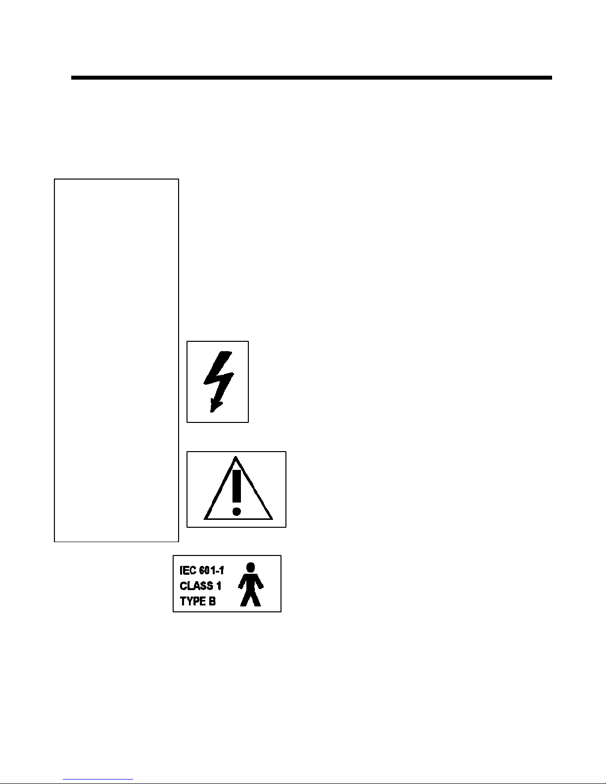
Warnings, Cautions and Errors
Warning!
Accessory equipment
connected to the analog
and digital interfaces
must be
certified to the
respective IEC
standards (IEC950 for
data processing or IEC
60601-1 for medical
equipment)
Furthermore, all
configurations s hall
comply
with the system
standard IEC 60601-1-1
Everyone who connects
additional
equipment to the signal
input or signal output
port configures a
medical system,
and is therefore
responsible that the
system complies with
Cautions
the requirements of
the system standard
IEC60601-1-1
doubt, consult the
technical service
department or a local
representative.
.
.
If in
The GSI 61 Clinical Audiometer is designed to be used with a hospital grade outlet. Injury to
personnel or damage to equipment can result w hen a three-prong or two-prong adaptor is
connected between the GSI 61 power plug and an AC outlet or extension cord.
Audiometers which bear the Underwriters Laboratories, Inc
with accessories that have the proper electrical compatibility and are listed as meeting the
requirements of the UL Medical and Dental Equipment Standard. Connecti on of accessories
not meeting these requirements may result in electrical leakage currents in excess of those
allowed by the standard and present a potential electrical shock hazard to the person being
tested.
This warning icon found on the back of the LCD panel indicates dangerous voltage within the
panel. Access to the LCD pa nel is lim ited to authorized Grason-Sta dler
service representatives.
.
When testing with the High Frequency earphones, do not allow the
presentation of the signal at the maximum dB HL to exceed 10 m inutes.
The buildup of increased temperature can cause harm to the earphones.
This caution label refers the user to the accompanying literature and
manuals.
This icon indicates that the GSI 61 is in compliance with Class 1,
T ype B requirements of IEC 601-1.
.
label should be interconnected
Cautions
ii
The following is the list of status messages which will occur
with operation of the GSI 61 Audiomet er. These messages will
be displayed in one of the bottom three message areas.
1761-0100 Rev. B
Page 4

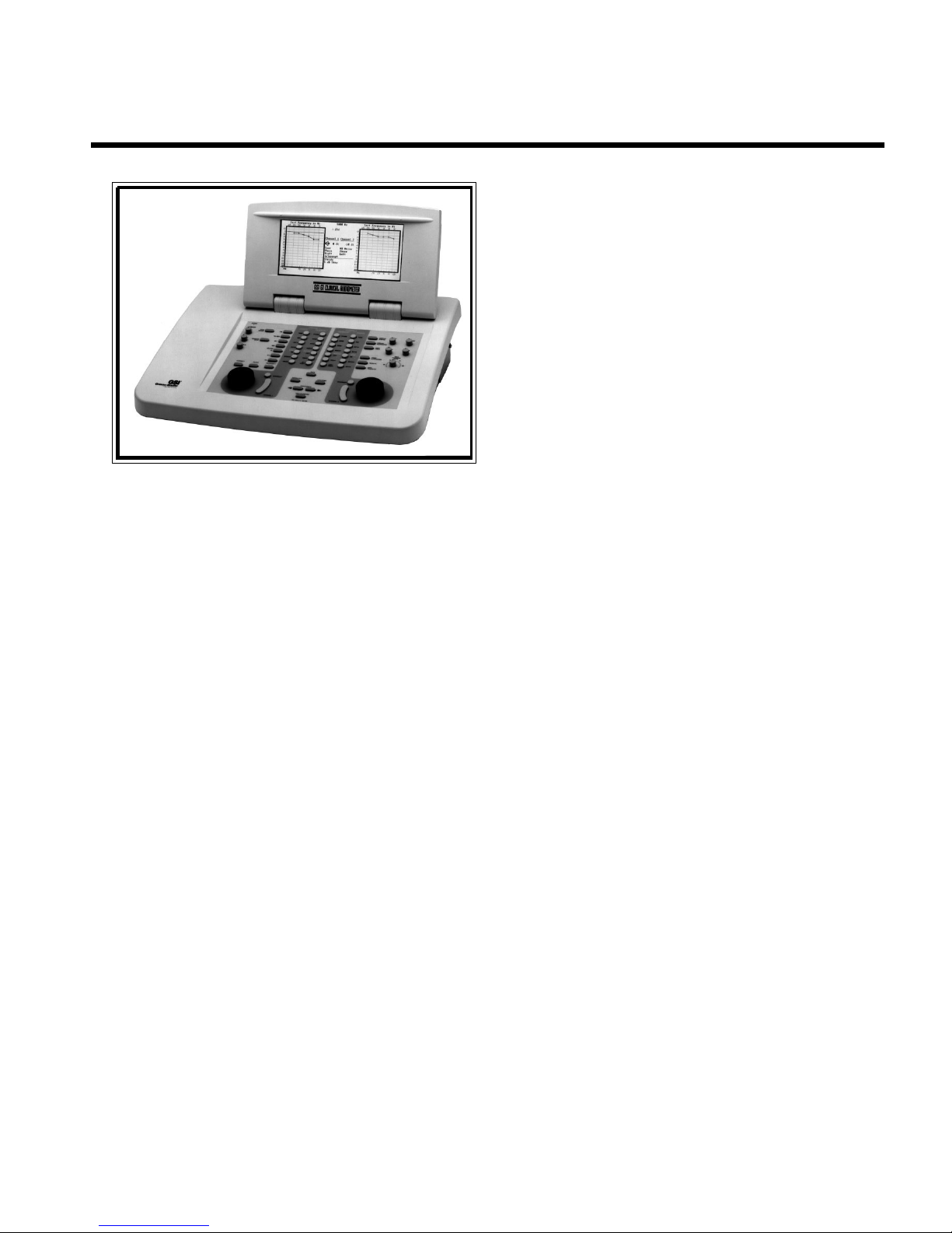
Grason-Stadler GSI® 61 CLINICAL AUDIOMETER
Status Messages
Using Default Data Indicates that the selected transducer and stimulus are not
Erasing Data Indicates that the GSI 61 is clearing stored test information.
Saving Data Indicates that the test information is being saved into memory.
No T est Data Stored Indicates that there is no test data available to be erased or
Check Hi-Freq Cables Indicates that the High Frequency function is enabled but the
Invalid Selection Indicates that an incorrect selection, such as incompatible
Not Available Indicates an uninstalled option has been selected.
No T est Data Stored Indicates that there is no data available for printing, although
Data T ransfer Indicates that data has been processed either by the printer or
Check Printer A check is done to see if the printer is connected and ready to
Printing This is an informational message which is displayed while
No Printer Response If communications problems occur during the course of printing,
calibrated to standard specified (ANSI/ISO) levels.
printed.
cables plugged into the L&R phone jacks are not the GSIspecified type.
transducers, has been made.
the Print Audiogram button has been pressed.
by a remote computer .
receive data by checking the hardware flow control line. If
printer is not ready this message will be flashed.
outputting data to the printer. It appears on th e lower right
section of the LCD.
this error message will be flashed.
Communications Error Messages
The following communication errors may occur during data transmission through the RS 232
communications:
Comm error: par ity Check GSI 61 and PC parity settings.
Comm error: framing Check GSI 61 and PC selections for number of stop
Comm error: overrun See ‘framing’.
Comm error: multiple Check parity, baud rate, number of stop bit s and
Comm er ror: spurious Soft error. Should not be repeata ble; if so, problem
Comm error: break See ‘spurious’.
If the word “Help” followed by an error code is displaye d, note the Help Code number . See the
GSI 61 Service Manual (1761-0110) for detailed descriptions of these. Turn off the power to
the GSI61 and wait 30 seconds. Restart the instrument. Often the error will be cleared by this
action. If the error persists, contact an authorized Grason-Stadler service representative.
bits and number of bits per comm and.
byte size on GSI 61.
could be anywhere in GSI 61 digital circuits or PC’ s
communication circuits.
1761-0100 Rev. B
iii
Page 5

Warranty
We, Grason-Stadler, warrant that this product is free from defects in material and
workmanship and, when properly installed and used, will perform in accordance with
applicable specifications. If within one year after original shipment, it is found not to
meet this standard, it will be repaired, or at our option, replaced at no charge except
for transportation costs, when returned to an authorized Grason-Stadler facility. If
field service is requested, there will be no charge for labor or material; however,
there will be a charge for travel expense at the service center’s current rate.
Note: Changes in the product not approved in writing by Grason-Stadler shall void
this warranty. Grason-Stadler shall not be responsible for any indirect, special or
consequential damages, even if notice has been given in advance of the possibility of
such damages.
THIS WARRANTY IS IN LIEU OF ALL OTHER WARRANTIES, EXPRESSED OR
IMPLIED, INCLUDING BUT NOT LIMITED TO, ANY IMPLIED WARRANTY OF
MERCHANTABILITY OR FITNESS FOR A PARTICULAR PURPOSE.
1761-0100 Rev. B
iv
Page 6
Specifications
Standards
Pure Tone - Channel
1 and Channel 2
The GSI®61 Clinical Audiometer meets or exceeds the following st andards: ANSI S3.6-198 9;
ANSI S3.43-1992; IEC 645-1 (1992); IEC 645-2 (1993); ISO 389; UL 2601-1 Medical Electrical
Equipment; IEC 601-1 Medical Electrical Equipment and CSA C22.2, No. 601.1-M90
Electromedical Equipment.
The CE mark on this product indicates it conforms with the provisions noted in the 93/42/EEC
Medical Devices Directive.
CE Mark per Medical Device Directive (93/42/EEC)
0344
European Authority Representative
Grason-Stadler A/S
Kongebakken 9
2765 Smørum
Denmark
Frequency Range
Air Conduction 125 Hz to 12000 Hz
High Frequency (optional) 8 k Hz to 20 k Hz
Bone Conduction 250 H z to 800 0 Hz
Sound Field (optional) 125 Hz to 12,000 Hz (125 Hz to 16,000 Hz
only with High Frequency option, 1761-9630, enabled)
Paired Insert (optional) 125 Hz to 8000 Hz
Single Insert (optional) 250 Hz to 6 000 Hz
Accuracy ± 1 %
T otal Harmonic Distortion £2% (earphones and paired insert phones*)
£5% (bone vibrator)
Intensity Range **
Air Conduction: -10 dB HL to 120 dB HL
High Frequency:* -20 dB HL to 100 dB HL (with Sennheiser HDA 200
Phones)
Bone Conduction:
Mastoid -10 dB HL to 80 dB HL
Forehead -10 dB HL to 70 dB HL
Sound Field:* -10 dB H L to 96 dB H L
Paired Inserts:* -10 dB HL to 110 dB HL
Single Insert:* -10 dB HL to 110 dB HL
Masking Intensity Range (Calibrated in effective masking)
Narrow Band N oise: Maximum dB HL is 15 dB below tone
White Noise: Maximum dB HL is 30 dB below tone
* Optional accessories
** The maximum HL values are applicable to the middle frequencies only.
GSI® 61 is a registered trademark o f Grason-Stadler. All rights reserved.
1761-0100 Rev. B
v
Page 7

Grason-
S
tadler GSI® 61 CLINICAL
Speech Channel 1 and
Channel 2
Microphone: For live voice testing and comm unications
External A and External B: Accepts recorded speech material from external
stereo tape cassette or CD player
Intensity Range:
Air Conduction: -10 dB HL to 105 dB HL
Bone Conduction:
Mastoid -10 dB HL to 65 dB HL
Forehead -10 dB HL to 55 dB HL
Sound Field:*** -10 d B HL to 90 d B HL
Paired Inserts:*** -10 dB HL t o 95 dB HL
Single Insert:*** -10 dB H L to 95 dB H L
Masking Intensity Range
Speech Noise:
Air Conduction (TDH 50P and Ins ert Phones *) and Bone
Conduction
Maximum dB HL are the same as the speech type signals.
Sound Field: -10 dB HL to 80 dB HL
White Noise: Equal to Speech Noise
*** Optional Accessories
Steady: Tone continuously present.
Pulsed: T one pulsed 200 mSec ON, 200 msec OF F .
FM : Tone modulated ± 5% of cente r frequency at a rate of 5 Hz.
Signal Format
Special Test
Capabilities
Communications and
Monitoring
Dimensions and
Weight
ALT : T one alternating between Channel 1 an d Channel 2: Cha nnel
1 is 400 mSec ON, 400 mSec OFF followed by Channel 2, 400 mSec
ON, 400 mSec OFF .
SISI: An intensity increment is added to a tone in the selected channel for
200 mSec, every 5 seconds. The HL increments are available in 1, 2
or 5 dB steps.
High Frequency: T one testing in the freque ncy range of 8 kHz to 20 kHz
using High Frequency phones or Sound Field.
The frequencies available for testing are: 8 kHz, 9 kHz,
10 kHz, 11.2 kHz, 12.5 kHz, 14 kHz, 16 kHz, 18 kHz
and 20 kHz (Optional).
Talk Forward: Permits the tester to speak through the test microphone into the
selected transducer at the intensity level set by the front panel
controls.
Talk Back: Allows the tester to listen to comments from the subject in the
testing booth.
Monitor: Th e monitor h ead set or monito r speak er can be u sed b y the tester
to listen to Channel 1, Channel 2 and/or T a lk Back signals.
W x D x H : 20 inche s x 15 inches x 12.6 inches (LCD raised)
50 cm x 39 cm x 32 cm
Height with LCD lowered - 6 inches (15 cm)
Weight: 19 pounds 8.7 kg
Shipping Weight: 30 pounds 13 .6 kg
vi
1761-0100 Rev. B
Page 8

Instrument Specifications
Power Consumption
Accessories Supplied
Optional Accessories
90 Watts
Test Headset (Matched set TDH-50P) -------------------------------------------------- 8000-0063
Bone Vibrator (B71) ----------------------------------------------------------------------- 8000-0130
Subject Response Handswitch ----------------------------------------------------------- 7874-0156
Test Microphone/Monitor Headset with coiled cord ---------------------------------- 1761-9623
Talk Back Microphone -------------------------------------------------------------------- 8000-003 9
Patch Cords, 6 ft. Grey (4/each) ------------ ---------------------------------------------- 4204-0505
Power Cord --------------------------------------------------------- (Country and voltage specific)
Instruction Manual - English -------------- -- -- -------------------------- -- --------------- 1761-0100
Instruction Manual - Spanish ------------ -- -- -------------------------- -- ----------------- 1761-0104
GSI Suite Audiometic Data Management Software ---------------------- ------------- 1010-9600
CD Player ----------------------------------------------------------------------------------- 1761-9621
Stereo Tape Cassette -------------------------------- -------------------------------------- 1761-9622
Speakers, Basic (90 dB) with cables (125 - 16 kHz) ------------------------------------- 1761-9630
Speakers, High Performance (96 dB) with cables (125 - 8 kHz) ----------------------- 1761-9635
Booster Amplifier (220-240V) with cables,
for use with the High Performance Speakers only----------------------------------- 1761-9636
Booster Amplifier (100-120V) with cables,
for use with the High Performance Speakers only----------------------------------- 1761-9637
Sound Field System, High Performance (102 dB, 220-240V , 125 - 8 kHz)
includes High Performance Speakers and Booster Amp ---------------------------- 1761-9638
Sound Field System, High Performance (102 dB, 100-120V , 125 - 8 kHz)
includes High Performance Speakers and Booster Amp ---------------------------- 1761-9639
Paired Insert Phones (E•A•R TONE
E•A•R TONE
E•A•R TONE
TM
Replaceme nt Foam Eartips , Std----------------------------------------- 1700-9604
TM
Replac ement Foa m Eartips , Small -------------------------------------- 1700-9605
TM
3A) ----------------------------------------------- 1700-9606
Single Insert Phone (470) -------------------------------- ---------------- ---------------- - 1700-9609
High Frequency Headphones w/booth cables ----------------------------------------- 1761-9602
High Frequency Cables (to sound booth) --------------------------- ------------------- 1761-9603
(If using High Freq Headphones, these cables are required to connect to the GSI 61)
High Frequency Headphones w/cables to GSI 61 ---- ---- ---- ---- ---- ---- ---- ---- ---- - 1761-96 04
High Frequency Cables (to GSI 61) ---------------------- -------------------- ------------ 1761-9605
(If using High Freq Headphones, these cables are required to connect to the GSI 61)
Remote RS 232/Pr inter Inter face -------------------------- -------------------------- ------ 1761-9680
Printer, Color (North Am erica only) ------------------------------------------------------ 1761-9610
Service Manual ----------------------------------------------------------------------------- 1761-0110
Audiocups ---------------------------------------------------------------------------------- 8000-0155
OtoAccess (Network Software for GSI Suite) --------------------------------------- 1015-9600
1761-0100 Rev. B
vii
Page 9

E
F
G
Grason-Stadler GSI® 61 CLINICAL
Catalog Listings
GSI 61 Clinical AudiometerwithoutRemote
English ---------------------------------------------------------------------------------- 1761-9700-XX
French ------- -------------------------- -------------------------------------------------- 1761-9700-XX
German --------------------------------------------- ------------------------ ------------- 1761-9700-XX
Italian -----------------------------------------------------------------------------------1761-9700-XXI
Spanish --------------------------------------------------------------------------------- 1761-9700-XXS
GSI 61 Clinical Audiometer with USB Remote
English ---------------------- ------------------------------------------------ -- -- -- ---- 1761-9780-XXE
French --------------------------------------------------------------------------------- 1761-9780-XXF
German ----------------------------------------- --------------------------------------- 1761-9780-XXG
Italian -----------------------------------------------------------------------------------1761-9780-XXI
Spanish--------------------------------------------------------------------------------- 1761-9780-XXS
Notes -XX refers to the voltage and plug requirements for the country of operation.
viii
1761-0100 Rev. B
Page 10
Electromagnetic Compatibility (EMC)
1761-0100 Rev. B
ix
Page 11

Table of Contents
Preface
Chapter 1
Introduction
Chapter 2
Installation
Title---------------------------------------------------------------------------------------------------------i
Warnings, Cautions and Errors- -----------------------------------------------------------------------ii
Warranty -------------------- -- -------------------------- ------------------------------------------------iv
Specifications ------------------------------------------------ -- -------------------------- -- -- -----------v
Standards -------------------------------------------------------------------------------------------v
Pure Tone - Channel 1 and Channel 2 --- ------------------------------------------------------v
Speech Channel 1 and Channel 2 --------- -----------------------------------------------------vi
Signal Format ---------------------- -- -------------------------- -- -------------------------- -------vi
Special Test Capabilities ------------------------------------------------------------------------vi
Communications and Monitoring --- --------------------------------------------------- --------vi
Dimensions and Weight------------------------------ ------------------------ --------------------vi
Power Consumption ---------- -------------------------------------------------------------------vii
Accessories Supplied----------------------------------------------------------------------------vii
Optional Accessories ----------------------------------------------------------------------------vii
Catalog Listings ---------------------------------------------------------------------------------viii
Electromagnetic Compatibility (EMC)-------------------------------------------------------------ix
Introduction ------------------ -- -- -------------------------------------------------- ------------------- 1-1
External Inspection --------------------------------------------------------------------------------- 2-1
Unpacking ------------------------------------------------------------------------------------------- 2-1
Accessories Supplied ------------------------------------------------------------------------------ 2-1
Connectors, Controls and Indicators ------------------------------------------------------------- 2-2
Rear Panel -------------------------------------------------------------------------------------------- 2-2
Left Side Panel--------------------------------------------------------------------------------------- 2-4
Right Side Panel ------------------------------------------------------------------------------------- 2- 4
Front Panel Controls -------------------------------------------------------------------------------- 2-5
V ali d Stimuli Combi nations --------------------------------------------------------------------2-8
V alid T ransducer Combinations --------------------------------------------------------------2-8
Displays ----------------------------------------------------------------------------------------2-14
Test Microphone/Monitor Headset ----- ------------------- ------------------ ------------------ - 2-17
Optional Accessories ------------------------------------------------------------------------------2-18
Hearing Level And Freque ncy Limits------ ---------------- -------------- -------------- ----------2 - 2 4
Initial Installation ----------------------------------------------------------------------------------2-26
Single Room Environment ------------------------------------------------------- ------------2-27
Two Room Installation ------------------------ ------------------------------ ------------------2-27
Loudspeaker Installation ---------------------------- -----------------------------------------2-29
1761-0100 Rev. B
Contents-1
Page 12

Grason-Stadler GSI® 61 CLINICAL AUDIOMETER
Grason-Stadler GSI® 61 CLINICAL AUDIOMETERGrason-Stadler GSI® 61 CLINICAL AUDIOMETER
Chapter 3
Operation
Preliminary Checks--------------------------------------------------------------------------------- 3-1
Patient Instructions ----------------------- ---------- -------- -------- ---------- -------- ---------- ---- 3-2
Placement of the Earphones ---------- --------------------------------------------------------3-2
Placement of the Insert Phone ---------------- ------ ------ ------ ------ ------ ------ ------ ------ 3-2
Placement of the Bone Vibrator ---------------------------------------------------------------3-2
Routine Test Procedures ------------- ------------------------ ------------------------------------- 3-3
Threshold Determination (Pure Tone): Modified Hughson-Westlake ------ -- -- -- -- ----3-3
Spondaic Speech Testing, Speech Reception Threshold (SRT) --------------------------3-4
Speech Discrimination (PB Words) -----------------------------------------------------------3-4
Chapter 4
Special Test
Procedures
Alternate Binaural Loudness B alance (ABLB) or Fowler T est -------------------------- ------ 4-2
Monaural Loudness Balance (MLB) Test -------------------------------------------------------- 4-3
Short-Increment Sensitivity Index (SISI) --------------------------------------------------------- 4-4
Modifications to the SISI test ---------------------------------------------------------------- 4-4
High Frequency Testing (Optional)------------------------------------------------------------- -- 4-5
High Frequency Testing: Setup Diagrams ---------------------------------------------------4-5
Sensorineural Acuity Level (SAL) T est ---------------------------------------------------------- 4-6
Hearing Aid Evaluation -------------- -------------------------- -- -------------------------- -- ------ 4-6
Tone Decay Test ------------------------------------------------------------------------------------ 4-8
Lombard or Voice-Refl ex T est ---------------------------------------------------------------------- 4-8
Delayed Auditory Feedback (DAF)--------------------------------------------------------------- 4-9
Staggered Spondaic Word Test (SSW)---------------- ------------------------------------------4-10
Doerfler-Stewart T est ------------------------------------ ---------------------- --------------------4-1 1
Modified Doerfler-Stewart Test--------------------------------------------------------------4-11
Pure Tone Stenger Test ---------------------------------------------------------------------------4-12
Chapter 5
Routine
Maintenance
Biological Calibration Che ck ----------------------------------------------------------------------- 5-1
Periodic Checks ------------------------------ ------------ ------------ ------------ ------------ ------- 5-1
Calibration Reference Levels ---------------------------------------------------------------------- 5-3
Line Voltage Brownout and Interruptions ---------- ---------------- ---------------- -------------- 5-6
The Message “CAL” -------------------------------------------------------------------------------- 5-6
The Message “Help” -------------------------------------------------------------------------------- 5-6
Contents-2
1761-0100 Rev. B
Page 13

T able of Content s
y
Chapter 6
Remote Options
RS 232 Configuration --------------------------------------------------------------------------------6-1
USB Overview ---------------------------------------------------------------------------------------- 6-3
Driver Installation and System Setup -------------------------------- ------------------------------6-4
GSI Suite -------------------------------------------------------------- ------------------------ ---------6-4
Data Flow Control Operation ------------------ ---------------- ------------------ ---------------- --- 6-5
Hardwa re Flow Contro l -------------------------------------- -------------------------- -------- 6-5
Softwa re Flow Co ntrol -------------------------------------- ------------------------ ----------- 6-5
Cable Connections---------------------------- ------------------------------------------------- 6-5
Data Transfer ----------------------------------------------------------------------------------------- 6-6
Record and Field Formatting ------------------------------------------------------------------ 6-6
Checksums -------------------------------------------------------------------------------------- 6-6
Remote Input Operation----------------------------------------------------------------------------- 6-7
Input Record Type -------------------------------------------- ---------------------------------- 6-7
Input Record Type 1 to 4 ---------------------------------------------------------------------- 6-7
Input Record Type 5 - Pushbutton Code Record ------------------------------------------- 6-7
T ype 6- Set Test Frequency Record --------------------------------------------------------- 6-11
T ype 7 - Set HL Record ------------ ------------------------ ---------------------- ------------- 6-12
Remote Output Operation---------------------------------------------------------------------------6-13
T ype 1- GSI 16 Compatible Short Data Record--------------------------------------------- - 6-13
T ype 4 - Error Record -------------------------------------------------------------------------- 6-16
Type 5 - GSI 61 Short Data Record ----------------------------------------------------------6-16
T ype 6 - Test Battery Data Record ------------------------------ ---------- ---------- ---------6 -18
Rec ord Pre fix ------------------------ ------------------------------------------ -----------------6-18
Left Ear T est Data - Pure T one ---------------------------------------------------------------6-18
Speech Test --------------------- ------------ -------------- -------------- ------------ -----------6-20
SISI Test ------------------------ -------------- ------------ -------------- -------------- ----------6-2 0
Alter nate (AB LB) ----------------------- ---------------------------------- ---------------------6-22
Right Ear T est Data ----------------------------------------------------------------------------6-23
Record Term inator ----------------------------------------------------------------------------6-23
T ype 7 - Instru ment Type --------- ------ ------ ------ ------ ------ ------ ---- ------ ------ ------ --6-2 3
Remote Output Operation continued ----------- --------------------------------------------------6-24
T ype 8 - Unit Configuration Record ---------------------------------------------------------6-24
Appendix
Bibliography
Regulatory
S
mbols
Test Words ---------------------------------------------------------------------------------------- A1-1
Part One -------------------------------------------------------------------------------------------- A1-1
Part Two -------------------------------------------------------------------------------------------- A1 -1
Bibliography ------------ ---------------------- ---------------------- ------------------------ ---------- B-1
Bibliography for Test Procedures ------------ -------------- -------------- ---------------- --------- B-2
Regulatory Symbols------------------------------------------------------------------------------------C-1
1761-0100 Rev. B
Contents-3
Page 14

Grason-Stadler GSI® 61 CLINICAL AUDIOMETER
Blank page.
Contents-4
1761-0100 Rev. B
Page 15
n
Chapter 1
Introduction
for the test sequence. The Tracking pushbutton allows the operator to synchronize intensity
changes on Channel 2 with those m ade on Channel 1.
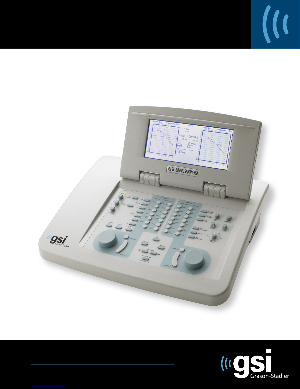
All data, including the instrument selected parameters, are displayed on an articulating Liqui d
Crystal Display (LCD). Pure tone test results are presented in either a “status” or an audiogram
format. The status format clearly shows all test conditions and permits the calibration check
of input from the microphone or from recorded test materials. The audiogra m format for pure
tone testing displays the stored threshold values for the patient un der test. The display can
be tilted to improve the viewing angle for an individual user and to allow easy access to the
rear jack panel.
Introduction
The GSI 61 Clinical Audiometer is a microprocessor controlled,
two channel audiometer for use in the clinical/diagnostic
environment. It has two separate sets of controls, one for eac h
of the channels. Each channel can be operat ed indepe ndentl y
by its tone bar, or the two channels can be activated
simultaneously through use of the interlock button.
The GSI 61 permits the output routing of the test signal through
earphones (matched TDH-50P), a bone vibrator (B71), optional
loudspeakers, optional paired I nsert Phones (EAR) or sing le
Insert Phone, and optional High Fre quency ( Sennheiser HDA
200) Earphones.
The diagnostic tests are easily selected through use of the
ergonomically designed front key panel. Flexible routing
selections permit the user to select that which is appropriate
The GSI 61 provides testing capabilities for a standard battery of diagnostic audiometric tests
including ABLB, SISI, Tone Decay, Stenger, Doerfler-Stewart, Lombard, and Staggered
Spondaic Word test (using a three head tape recorder). The High Frequency option extends
the frequency range (from 8 kHz to 20 kHz) for ototoxic dru g monitoring.
The GSI 61 has the optional capability of printing the stored audiogram data or of sending the
data to a remote computer through an RS 232 or USB interface. The RS 232 and USB interface
a re bidirect ional to allow the operator to transmit test results to a computer and to control the
audiometer from a remote computer system. The transmittable data record can be configured to
be either a single value (threshold and frequency) or battery transfer (all stored parameters for
a patient).
1761-0100 Rev. B
1-1
Page 16

Grason-Stadler GSI® 61 CLINICAL AUDIOMETER
Blank page.
1-2
1761-0100 Rev. B
Page 17
k
t
t
n
Chapter 2
Installation
External Inspection
Although this GSI 61 Clinical Audiometer was carefully tested, inspected and packed
for shipping, it is good practice after receiving the instrument to immediately examine
the outside of the container for any signs of damage. Notify the carrier if any damage
is observed.
Unpacking
Carefully remove th e GSI 61 from its shipping container. If the instrument appears
to have suffered mechanical damage, notify the carrier immediately so that a proper
claim can be made. Be certain to save all packing material so that the claim adjuster
can inspect it as well. As soon as the carrier has completed the inspection, notify
a Grason-Stadler representative.
If the instrument must be returned to the factory, repack it carefully (in the original
container, if possible) and return it prepaid to the factory for the necessary adjustments.
Check that all accessories itemized below are received in good condition. If any
accessories are missing, a Grason-Stadler representative should be notified
immediately.
Installation
2
See the Specifications Section of this manual for the catalog numbers of accessories
and also for a listing of the optional accessories.
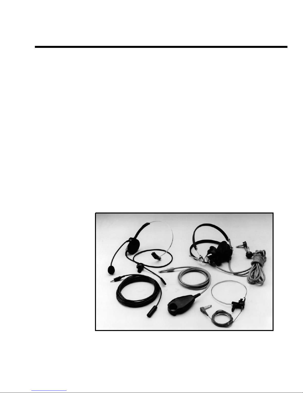
Accessories Supplied
Test Microphone /
Monitor Headset
Patient Talkbac
Microphone
Patien
Handswitch
Response
Test Headset
Assembly
Bone
Vibrator
Assembly
Not Shown: For Sound Booth use:
her
O
1761-0100 Rev. B
Handswitch Patch Cord (1)
Bone Vibrator Patch Cord (1)
Earphone Patch Cord (2)
:
Instruction Manual.....Power Cord and
GSI Suite CD
2-1
Page 18
Grason-Stadler GSI® 61 CLINICAL AUDIOMETER
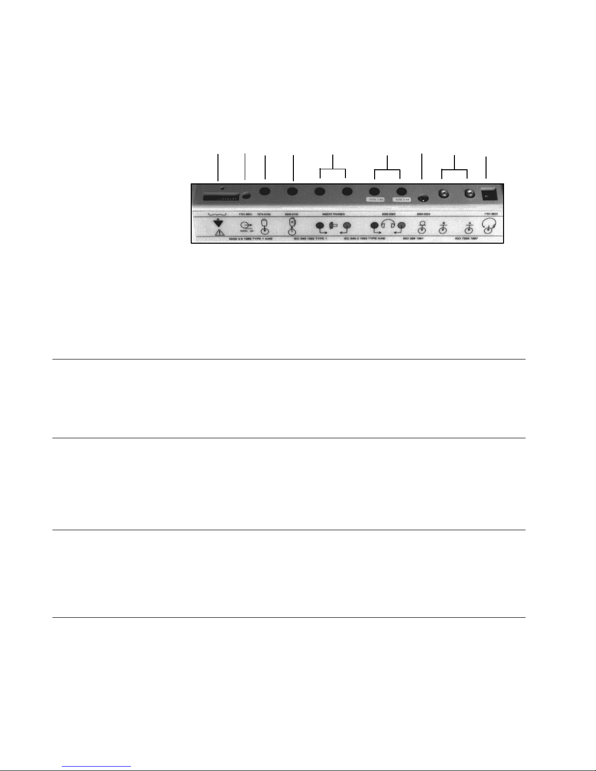
Connectors, Controls and Indicators
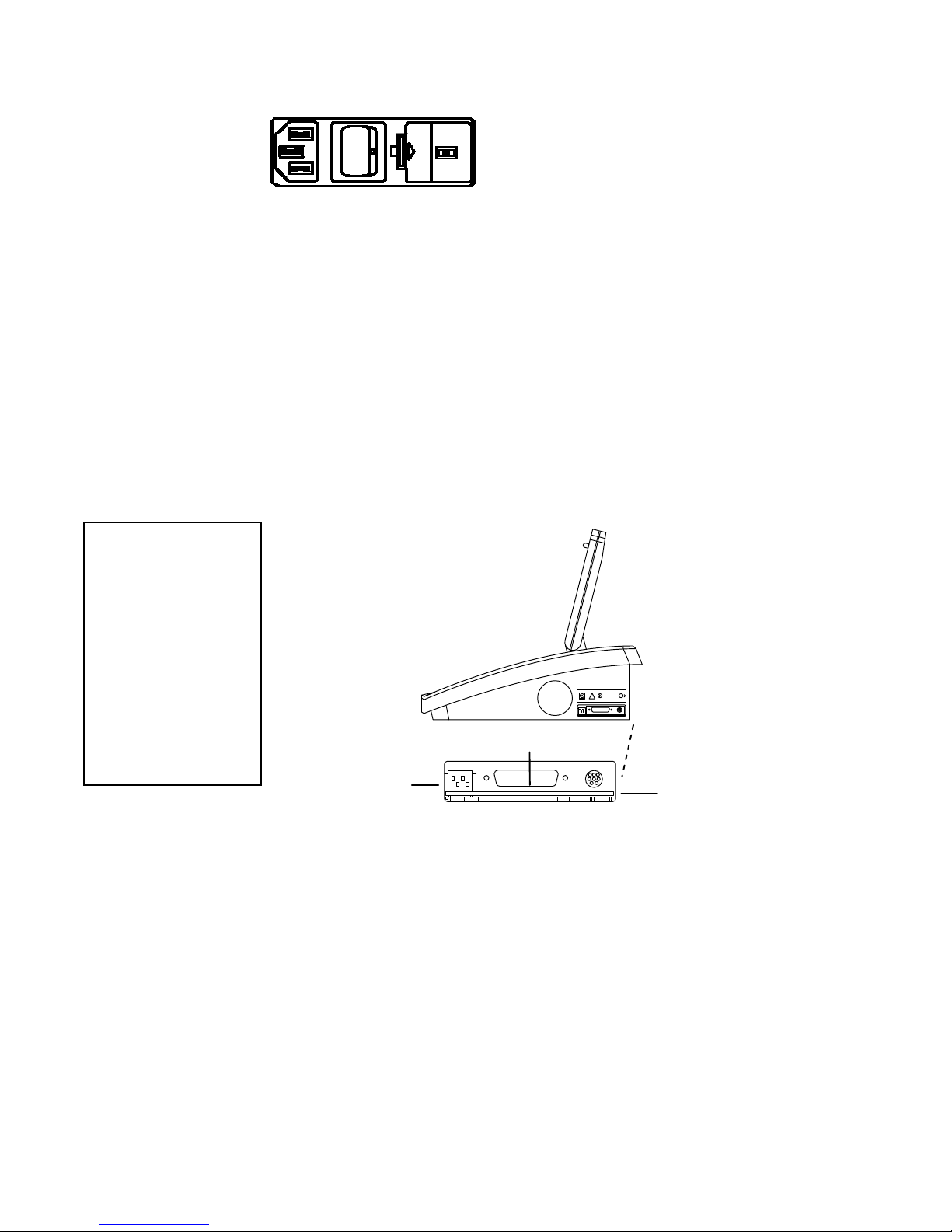
Rear Panel
R1 - Monitor
Headset
R2 - Ext A and Ext
B
The connectors on the rear panel of the GSI 61 are shown in the following diagram.
The label and jacks are visible looking down onto the instrument, behind the LCD.
R9 R8 R7 R6 R5 R4 R3 R2 R1
(Modular Phone Jack)
Pin Function
1
Mic High and +6 VDC 0.2 to 6.0 mV RMS 1.8 K ohm (output)
2
Phone Low GND 0 ohm
3
Phone High 3.0 mV to 1.0 V 300 ohm
4
Mic Shi eld GND 0 ohm
(RCA plug)
Output Voltage
Impedance
R3 - Talkback
Microphone
R4 - Left and Right
Ear
Phone Outputs
R5 - Left and Right
Input jacks for optional stereo tape cassette or CD player.
Voltage range required: 0.2 to 1.0 V to obtain 0 VU
Input Impedance: 15 K ohm
(3.5 mm stereo jack)
Position Function
1 Tip Mic High 0.2 to 2.0 mV RMS and +6V AC 10 K ohm
2 Ring Mic Low - - - - - - - - - -
3 Shield Chassis Ground - - - - - - - - - -
(1/4 inch stereo jack)
Stereo phone jacks for left (blue) and right (red) earphones, patch cords, or High
Frequency earphone connector cords.
Voltage: 1µV to 7.0 V RMS (4.45 V RMS for High Fre qu en cy )
Output impedance: 5 ohms or less
(1/4 inch monaural jack)
Output Voltage
Impedance
2-2
1761-0100 Rev. B
Page 19
Chapter 2 - Installation
Insert Phone Outputs Monaural phone jacks for left and right insert phones or patch cords.
Voltage: 1µV to 4.0 V
Output impedance: 5 ohms or less
Note: When the Single Insert Phone option is used, it must be plugged into the left
insert phone output.
R6 - Bone Vibrator (1/4 inch phone jack)
Jack for bone vibrator or gray patch cord.
Voltage: 200 µV to 5.00 V RMS
Output impedance: 5 ohms or less
R7 - Subject (1/4 inch phone jack)
Response
Handswitch Accepts plug from the cable attached to the patient’s response handswitch or
handswitch patch cord.
Pin Function Voltage Impedance
1 Shield GND 0 ohm
2 Digital GND GN D 0 ohm
3
Response input +5V/GND 1K ohm/0 ohm
R8 - CD Player Power (2 pin power jack)
Jack
Provides 5 V DC for CD Player.
R9 - Dip Switch/Cal An eighth position bank of switches accessible by an authorized service representative.
Switch
R10 – Speakers (5 pin Din connector) Located on rear of instrument.
Connects to left and right loudspeakers.
Pin Function Impedance
1
Left speaker (high) 1.0 ohm
2
Left GND 0 ohm
3
Right speaker (high) 1.0 ohm
4
Left speaker (low) 1.0 ohm
5
Right speaker (low) 1.0 ohm
SHLD Right GND 0 ohm
1761-0100 Rev. B
2-3
Page 20
r
Grason-Stadler GSI® 61 CLINICAL AUDIOMETER
Left Side
Panel
Right Side
Panel
Please Note:
The connectors on the left side panel are shown below.
The power entry module is composed of the power
switch, fuse drawer and voltage selection switch,
and power cord with hospital grade plug appropriate
for the country of destination.
When turned ON, the GSI 61 automatically initializes and displays a screen which
states the type of audiometer (IEC and ANSI specified for speech audiometry)
followed by a status screen. With the status display, the GSI 61 is brought to the
initialization state.
The frequency is set at 1000 Hz and:
Channel 1 Channel 2
Steady tone NB Noise
Phone-Right Phone-Left
0 dB HL -10 dB HL
Serial Port
This instrument has Remote and Printing capability, or t h e f o l l o wi n g connectors will be
visible on the right side panel of the GSI61:
Depending on the
date product
configuration
purchased, the GSI 61
is either equipped
with a Serial Port, a
USB Port, or no
Remote port at all.
RS 232 Remote Port
USB Remote Port
Printe
USB Printer Port
DIP Switches
2-4
Port
!
RS232
Printer Port
Dip Switches
Remote Port
Remote/Printer Option
A mini-DIN connector uses a standard Apple “Hayes Modem” cable (supplied) to
provide serial connection to th e equi pment.
A Standard A/B USB cable provides connection to a PC.
A 25-pin PC-Printer Interface Connector. Connects to t h e printer via a standard PCparallel printer cable.
A Standard USB cable provides connection to a printer. See Chapter 6 for more
For more detail on these DIP switch settings, and attaching and using a printer , refer to
the Optional Accessories section beginn ing on page 2-18.
1761-0100 Rev. B
Page 21
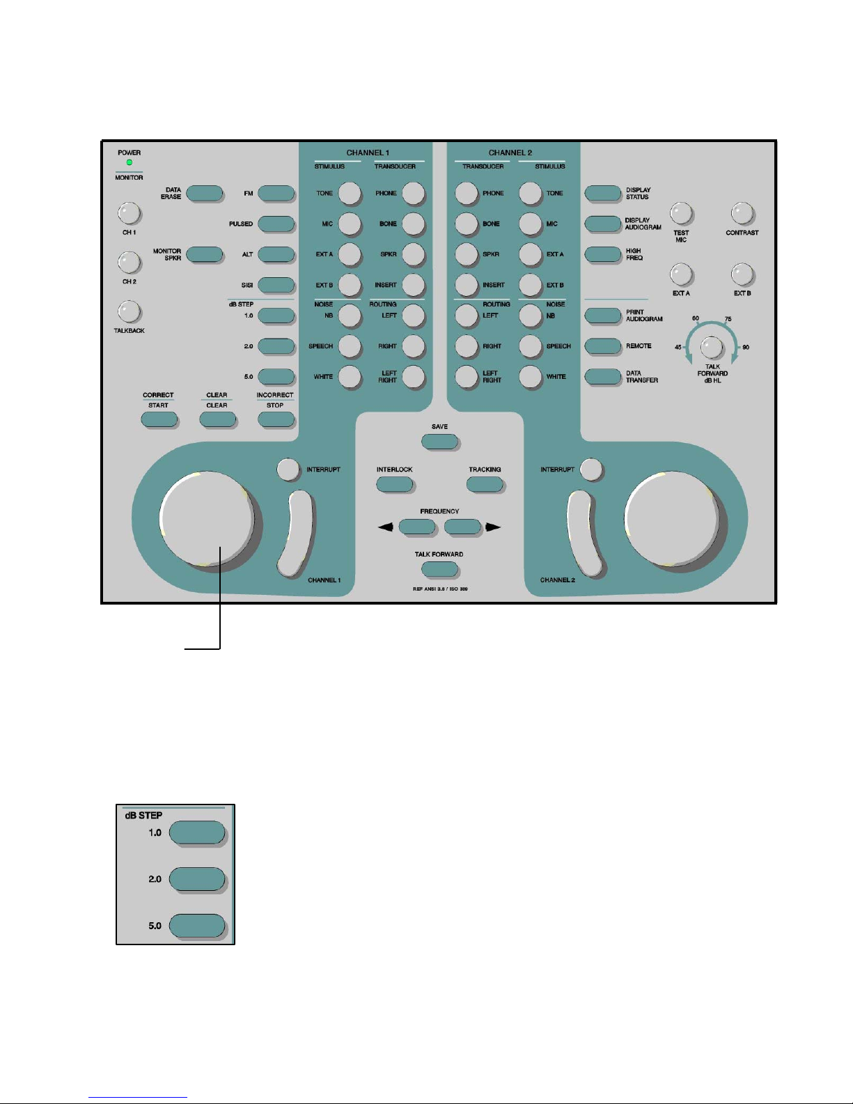
Front Panel Controls
p
The controls on the front panel of the GSI 61 are shown below.
Chapter 2 - Installation
Attenuators
(HL Controls)
Channel 1
and Channel 2
dB Ste
Size
The GSI 61 contains two independent HL rotary controls for test signal and masking
intensity l evel control with a ra nge of -10 dB HL to 120 dB HL (If the High Frequency
option using Sennheiser earphones is installed and active, the High Frequency intensity
level control ranges from -20 dB HL to 1 10 dB HL). Maximum dB HL values appl y
to the mid-frequencies with earphones only. Refer to the specific transducer for dB
HL limits in the Table on page 2-24.
These pushbuttons allow the operator to change the intensity step size to 1.0, 2.0 or
5.0 dB. When the GSI 61 is powered up, the dB step size is automatically set to the
.
default of 5 dB increments
These pushbuttons are also used to select the intensity
increase when testing in the SISI mode.
1761-0100 Rev. B
2-5
Page 22
Grason-Stadler GSI® 61 CLINICAL AUDIOMETER
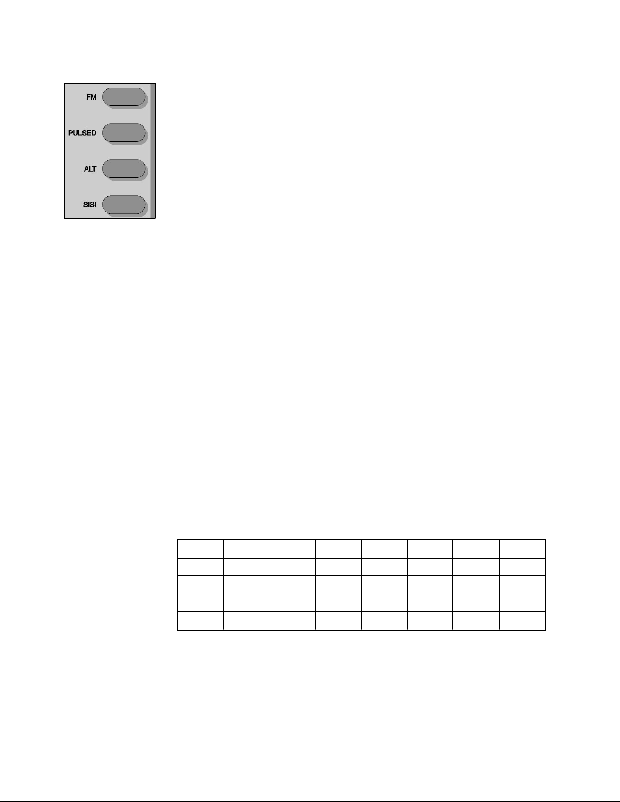
Signal Format (Frequency Modulation or Warble Tone)
Selectors FM - This pushbutton enables pure tones to be warbled at a rate of 5 Hz with a ± 5%
allowable deviation around the selected center frequency. FM is available in all pure
tone test modes, including SISI, Pulsed, ALT and High Frequenc y (optional).
Pulsed - This pushbutton causes the tone to be pulsed at the rate of 200 msec ON,
200 msec OFF. Note that the Pulsed tone is not available in SISI or ALTernate test
conditions. When a speech test mode is activated, Pulsed is no longer activated.
Alternate - This pushbutton locks both channels together and alternates the tone
presentation between the two channels: 400 msec ON Channel 1, 400 msec OFF
Channel 1, 400 msec ON Channel 2, 400 msec OFF Channel 2. Both channels
receive TONE as the input stimulus. The frequency is automatically set to 1000 Hz
and the dB step size, HL settings and the routing reflect the conditions prior to the
selection of ALTernate test type. The tones can be manually presented by depressing
either PRESENT bar or automatically presented by pressing either INTERRUPT
button. The intensity of the tones can be adjusted independently by use of the Channel
1 and Channel 2 attenuators.
SISI - This pushbutton provides an intensity increment every 5 seconds to a steady
or FM tone in the selected channel for 200 milliseconds. The SISI test may be run at
step sizes of 1.0, 2.0 or 5.0 dB. When SISI is selected, the GSI 61 automatically
initializes Channel 1 to receive tone and Channel 2 to receive NB noise. The step
size is initialized to 5.0 dB but may be changed to either 1.0 or 2.0 dB at any time
during the test. Channel 1 and Channel 2 are set to 0 dB HL; the frequency is set to
1000 Hz. Output transducer and routing reflects the state of the GSI 61 prior to the
selection of SISI. Depress the Interrupt pushbutton to allow the SISI increments to
be presented every 5 seconds. Press the Interrupt button a second time to terminate
the SISI presentation. (Operating the Channel 2 tone bar with Interlock selected in
SISI also terminates the SISI increment presentation).
In order to deselect the preselected signal format, change to any non-compatible test
stimulus or push the same signal format again. The following table illustrates the
compatibilities of test stimulus and signal formats.
VALID SIGNAL FORMATS / STIMULUS COMBINATIONS
TONE
MIC
FM
PULSED
ALT
SISI
V
V
V
V
X
X
X
X
EXT A
X
X
X
X
EXT B
NBN
SPEECH
WHITE
X
X
X
X
X
V
V
X
X
X
X
X
X
V*
V*
X
V =Valid combination of signal format and stimulus.
X = Invalid combination of signal format and stimulus.
* = When White/White is selected stimulus, calibration for White noise will
be for speech.
2-6
1761-0100 Rev. B
Page 23
Chapter 2 - Installation
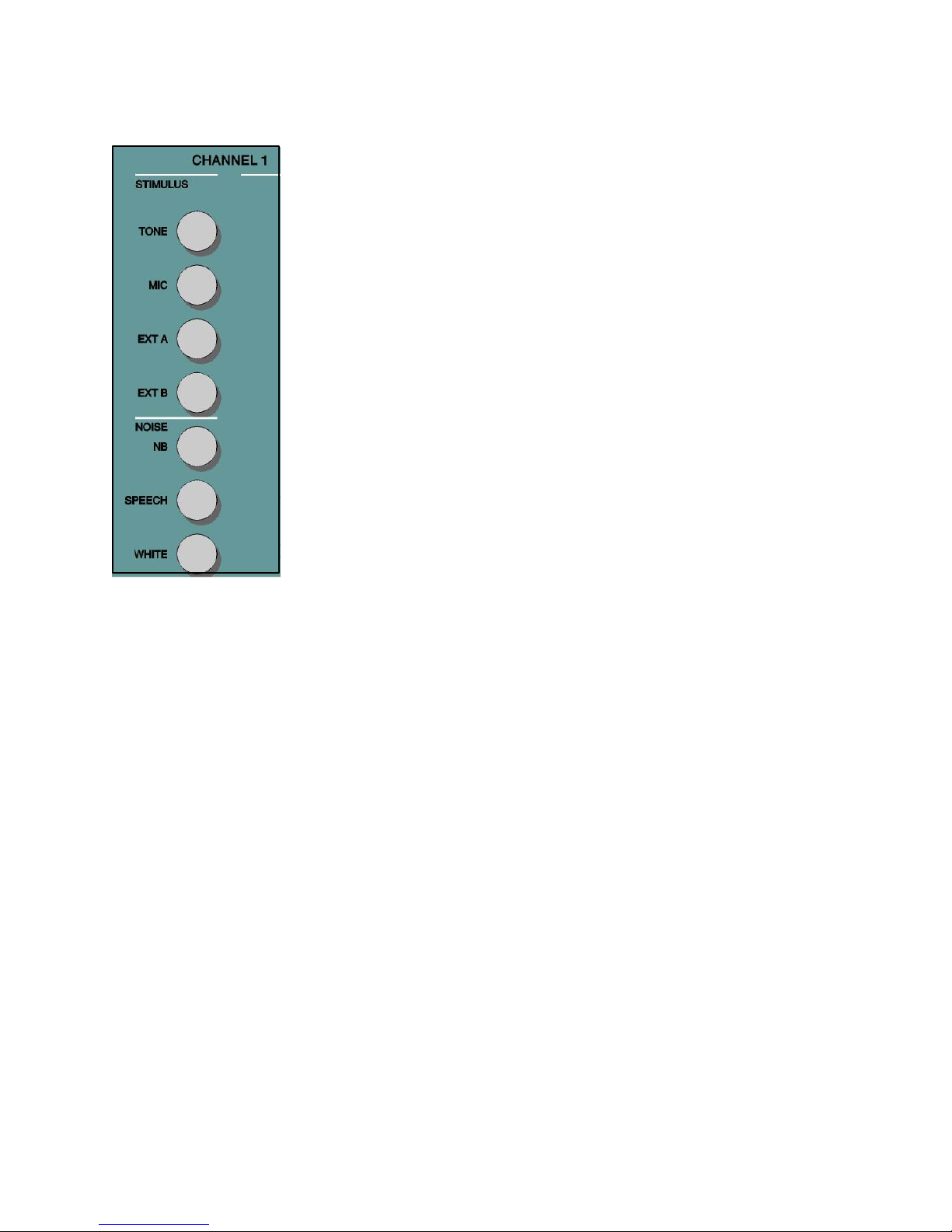
Stimulus Channel 1 Tone — The Tone pushbutton allows the selection of a pure tone presentation for
and Channel 2 air/bone conduction testing with the choice of four transducer types; Phone (both the
standard TDH 50P and the optional High Frequency earphones), Bone, Speaker, or
Insert. When Tone is selected, Narrow Band Noise automatically routes to the
opposite channel if the stimulus type on the opposite channel is not compatible with
Tone. Note that the selection of Tone on one channel and Mic on the opposite
channel is a valid combination. This setting allows the operator to have contact with
the patient, especially a young child, without the need to select Talk Forward.
Mic — The Mic pushbutton provides input capability from the test microphone for
live-voice testing with the choice of four transducer types: Phone, Bone, Speaker, or
Insert. When Mic is selected, Speech Noise automatically routes to the opposite
channel if the stimulus type on the opposite channel is not compatible with MIC.
Note that the selection of Mic on one channel and Tone on the opposite channel is a
valid combination. This setting allows the operator to have contact with the patient,
especially a young child, without the need to select Talk Forward.
Ext A, Ext B — External A and External B accept recorded speech material from
an optional compact disc player, a two channel tape cassette or a reel-to-reel tape
recorder . When Ext A or Ext B is selected on one channel, Speech Noise automatically
routes to the opposite channel if the stimulus type on the opposite channel is not
compatible with Ext A or Ext B. Note that the selection of Ext A, or Ext B, on one
channel and Tone on the opposite channel is a valid combination.
Narrow Band Noise — The NB Noise pushbutton selects narrow band noise.
This is a noise centered at each test frequency and available for all frequencies with
a 3 dB down bandwidth of greater than octave but less than ½ octave. The maximum
dB HL is 15 dB below the maximum pure tone level and is calibrated in effective
masking.
Speech Noise — The Speech Noise pushbutton selects speech noise. This is a
white noise filtered to a low and middle frequency band, simulating the average
.
spectrum of conversational speech
Speech noise is calibrated in effective masking
level and consists of equal energy per frequency from 250 to 100 Hz with a 12 dB/
octave roll-off from 1000 to 6000 Hz. The maximum dB HL for speech noise is
equal to the maximum HL for the speech type signals in each transducer.
White Noise — This pushbutton selects White Noise. White noise is a broad band
signal containing acoustic energy at all frequencies between 125 Hz and 12000 Hz.
White noise is calibrated for pure tone effective masking if a tone type signal is
selected on the opposite channel, and for speech effective masking if a speech type
signal is selected on the opposite channel. The maximum HL for white noise selected
with a tone signal is 35 dB below the maximum pure tone level. The maximum HL
for white noise selected with a speech signal is equal to the maximum HL for the
speech signal.
Refer to the following table for the stimuli compatibilities listing.
1761-0100 Rev. B
2-7
Page 24

Grason-Stadler GSI® 61 CLINICAL AUDIOMETER
Valid Stimuli Combinations
Channel 1 Stimulus
Mic
Ext A
Tone
Ext B NBNoise S Noise White Noise*
* If White Noise is selected
on both channels, then
calibration is made to speech.
If White Noise is selected on
one channel only, calibration
will be made to the stimulus
type on the opposite channel.
Transducer Output
Selector
Channel 2
Stimulus
Tone
Mic
Ext A
Ext B
NBNoise
S Noise
W Noise*
Valid
Valid
Valid
Valid
Valid
Invalid
Valid
Valid
Valid
Valid
Valid
Invalid
Valid
Valid
Valid
Valid
Valid
Invalid
Valid
Valid
Valid
Invalid
Valid
Valid
Valid
Valid
Invalid
Valid
Valid
Valid
Valid
Invalid
Valid
Valid
Invalid
Invalid
Valid
Invalid
Invalid
Valid
Valid
Invalid
Valid
Invalid
Valid
Valid
Invalid
Invalid
Valid*
These pushbuttons allow the easy selection of the transducer for each stimulus
available for Channel 1 and Channel 2. A transducer selection may be changed at
any time.
Valid Transducer Combin ation s
Channel 1
Bone
Speaker Insert
Valid
Valid
Valid
Valid
Valid
Valid
Channel 2
Phone
Bone
Speaker
Phone
Valid
Valid
Valid
Valid
Valid
Valid
Routing Output
Selector
Tone Bar / Interrupt
Insert
Valid
Valid
Valid
Valid
These pushbuttons allow the easy selection of the routing from the stimulus to the
output transducer available for Channel 1 and Channel 2. When first powered on,
the routing for Channel 1 will be right and the routing for Channel 2 is left. Left/
Right mixes the stimuli from both channels to each transducer and drives both the
left and right transducers with the combined signal. Both the Channel 1 and Channel
2 maximum dB HL limits in mixing are appropriately decreased from the non-mixed
maximum dB HL limits. Left/Right -Left/Right routing is restricted to Phone/Phone,
Speaker/Speaker and Insert/Insert (paired insert option). Left/Right routing is invalid
for bone and the single insert phone.
Each tone bar operates independently to present the selected stimulus for as long as the
bar is depressed. The channel turns off immediately when the bar is released. When
ALTernate is selected and the tone bar is released, the complete presentation of
both channel signals is completed. These pushbuttons determine the status of the
respective tone bars and operate independently of each other. When the Interrupt
is in the off position, the corresponding channel is activated by depressing the Tone bar
bar and deactivated by releasing the Tone bar. To turn on the Interrupt, press the
pushbutton. When Interrupt is in the on position, the corresponding channel is deactivated
by pressing the Tone bar and activated by releasing the bar. When Interrupt active,
an icon is displayed on the LCD. Note that in the ALTernate test mode, the Interrupt
pushbuttons do not operate independently of each other.
2-8
1761-0100 Rev. B
Page 25
Chapter 2 - Installation
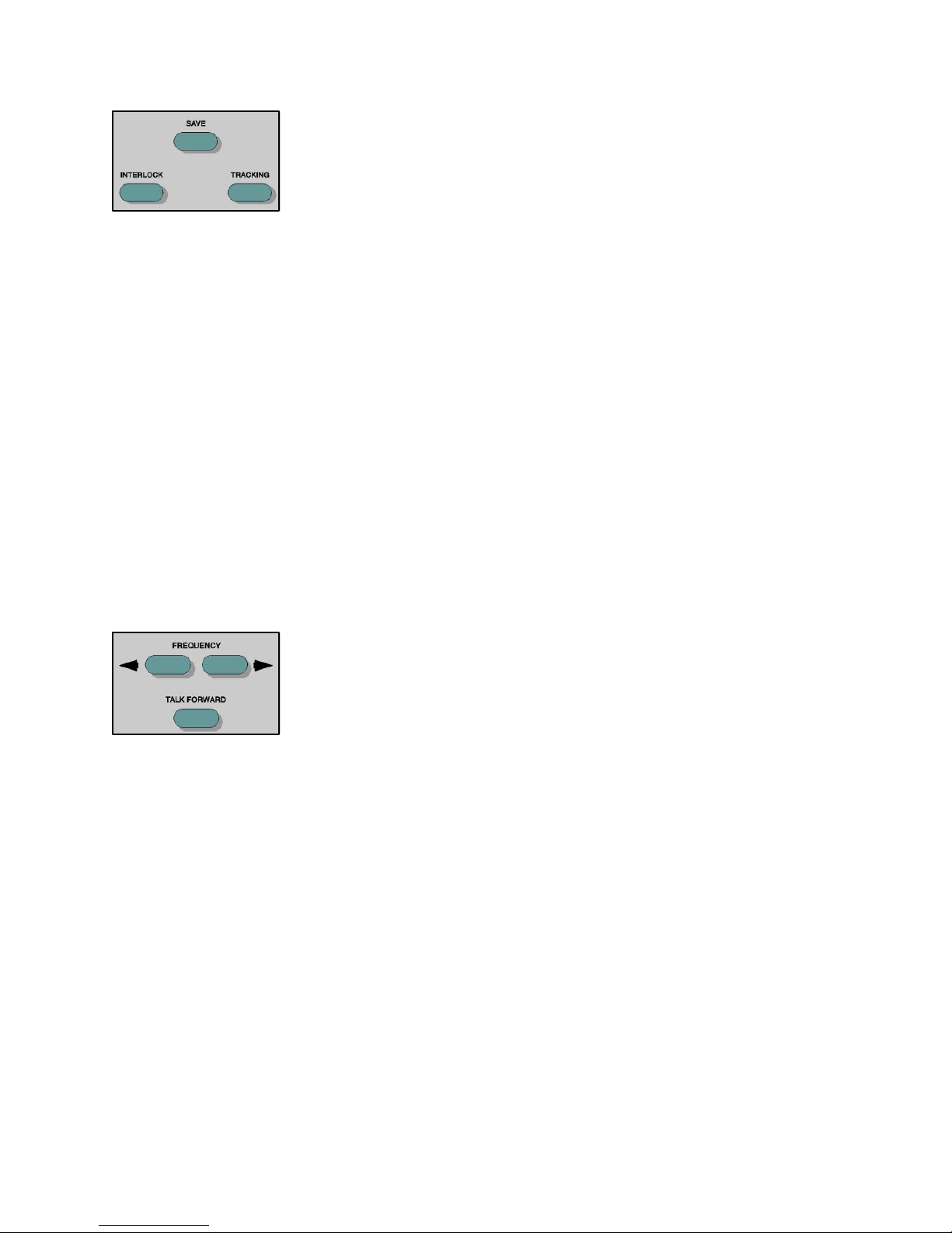
Interlock This pushbutton locks both tone bars together so that operating one channel will also
operate the other, according to the status of the Interrupt buttons. To unlock the
Tone bars, press the Interlock button again. When the Interlock is active, a message
is displayed on the LCD.
Save This pushbutton, when pressed, saves the current dB HL level representing the
threshold level, and effective masking level if selected, transducers and routing. In
the Display Audiogram format, the appropriate symbol appears for each Save press.
Tracking
This pushbutton allows the Channel 2 hearing level to track the Channel 1 hearing
level by a selected dB difference. When in Tracking, any dB change to the Channel
1 HL causes the Channel 2 HL to change by the same amount, until the limit of the
Channel 1 transducer is reached. If the dB HL limit is reached in Channel 2 before
Channel 1, the Channel 2 dB HL display will temporarily flash and remain at this
level. Tracking remains on. When the Channel 1 dB returns to a level at which the
selected difference between the two channels can resume, Channel 2 again tracks
Channel 1. Tracking is in the off state upon initialization of any test type. When
tracking is selected, it is possible to manually change the intensity of Channel 2 to
alter the dB difference between the two channels without deselecting Tracking. To
exit T racking, press the button again. When T racking is active, a message is displayed
on the LCD.
Frequency Up/Down These pushbuttons allow the choice of twelve standard audiometric frequencies: 125
Hz, 250 Hz, 500 Hz, 750 Hz, 1000 Hz, 1500 Hz, 2000 Hz, 3000 Hz, 4000 Hz, 6000
Hz, 8000 Hz and 12000 Hz. If the high frequency option is activated, these pushbuttons
allow a choice of nine high frequencies: 8 kHz, 9 kHz, 10 kHz, 1 1.2 kHz, 12.5 kHz,
14 kHz, 16 kHz, 18 kHz, and 20 kHz. Each press of the right (R) pushbutton selects
the next higher frequency. Each press of the left (L) pushbutton selects the next
lower frequency. The new frequency is selected when the pushbutton is released.
When at the lower limit of the frequency selection, pressing the (L)pushbutton will
cause the display to roll over to the highest frequency limit, and vice versa. If a
transducer with a narrower range is selected, only valid frequencies for that transducer
are available.
See the Table entitled “dB HL Limits per Frequency and T ransducer” in the Hearing
Limits and Frequency Levels Section (pages 2-24 and 2-25) for the allowable
frequency ranges of the specific transducers.
Talk Forward Pressing this pushbutton allows the operator to speak directly to the patient through
the microphone at the level set by the Talk Forward control by interrupting the stimulus
presentation. Talk Forward can be used with any available transducer , including the
optional High Frequency earphones. While Talk Forward is on, the only control
which can be activated is the Print, if available. The GSI 61 resumes the test status
held prior to pressing the Talk Forward pushbutton when the pushbutton is released.
1761-0100 Rev. B
2-9
Page 26
Grason-Stadler GSI® 61 CLINICAL AUDIOMETER
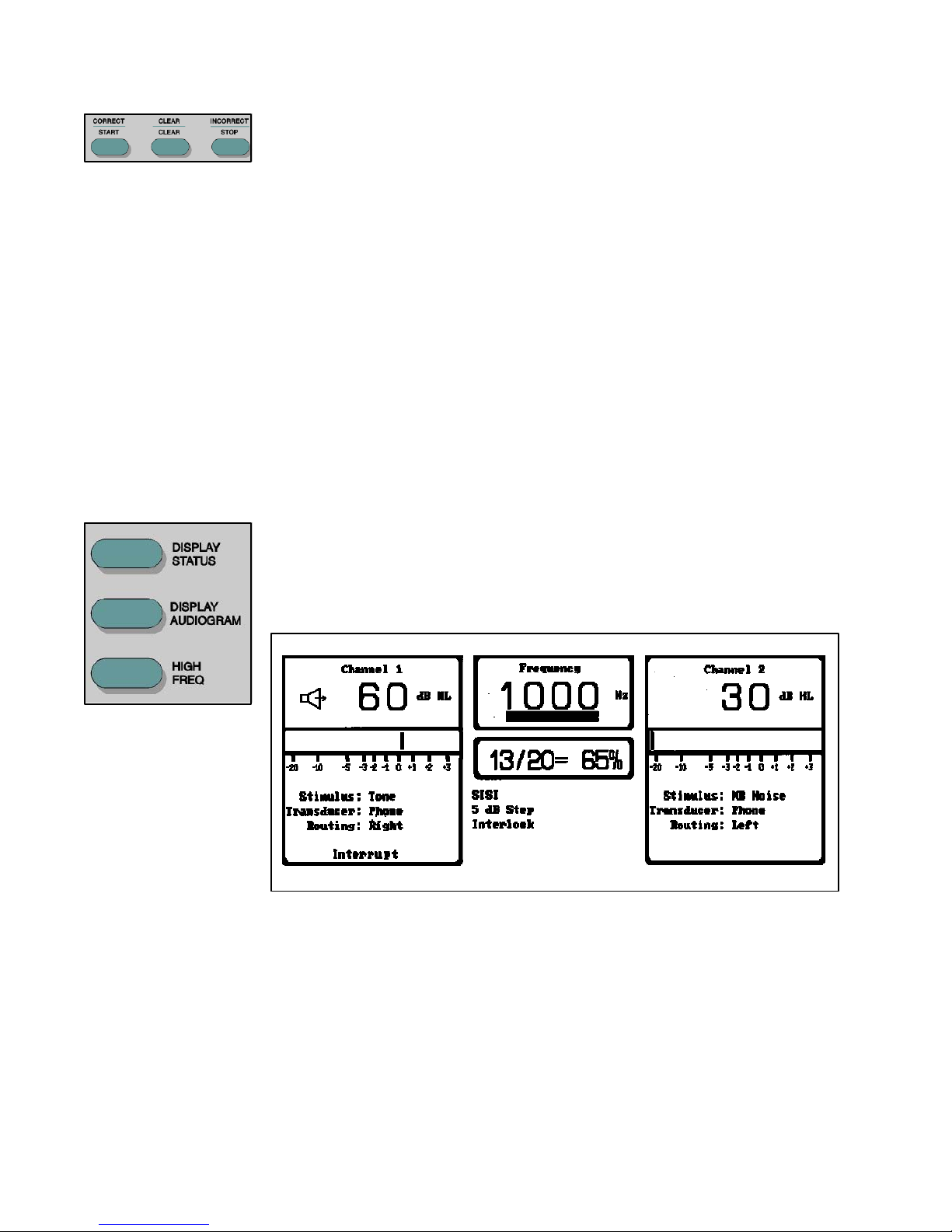
Scorer/Timer The Correct, Clear and Incorrect pushbuttons are used for scoring results in Speech,
ALTernate or SISI tests. The scorer is displayed in the test status area of the Status
screen. When Speech, SISI or ALT is selected, the scorer initializes to 0/0 = 0%.
The operator presses the Correct or Incorrect pushbutton after each presentation,
depending on the response. The display indicates the number of correct responses
and the total number of presentations along with the percentage of those correctly
identified. The display clears with the pressing of the Clear pushbutton.
During tone tests (excluding ALTernate and SISI), the Scorer/Timer pushbuttons
may be used to start, clear and stop the timer. The timer is displayed in the test
status area of the Status screen. When the timer is first selected, it initializes to 0:00
(0 minutes: 00 seconds). The timer starts when the Start pushbutton is pressed.
Times up to 199 minutes and 59 seconds may be displayed before the timer resets to
0:00. The timer may be halted at any point by pressing the Stop pushbutton. The
stopped time is displayed.
Upon pressing the Start pushbutton after the Stop
pushbutton, timing is resumed from the currently displayed value. Pressing Clear
while the timer is running is invalid. Pressing Clear after Stop resets the timer to
0:00.
Displays These pushbuttons are used to select the format for the screen display format on the
LCD.
Display Status — When the Display Status pushbutton is pressed, the display is
formatted as shown in the following Figure: Front Panel Display - Status. This
display indicates the current instrument state and VU meters.
Display Status
Display Audiogram — When the Display Audiogram pushbutton is pressed, the
display is formatted as shown in the following Figure: Front Panel Display -Audiogram.
Two audiograms with the standard range of frequencies (125 Hz to 12,000 Hz), or
the High Frequency ranges (8 kHz to 20 kHz), and the instrument status are displayed.
Hold the Display Status key for 2.5 seconds to view the left audiogram on the left
side, and right on the right side. Hold the Display Status key again to reverse back
to the original setting..
2-10
1761-0100 Rev. B
Page 27
Chapter 2 - Installation
Display Audiogram
High Frequency — When the High Frequency pushbutton is pressed with the High
Frequency option installed, the system allows tone testing in the extended range
from 8 kHz to 20 kHz. The display remains in the Display Status or Display Audiogram
format as previously selected. If the High Frequency option has not been installed
and the pushbutton is pressed, the error message “Not Available” appears in the
error message area of the display.
1761-0100 Rev. B
Display High Frequency
2-11
Page 28
Grason-Stadler GSI® 61 CLINICAL AUDIOMETER
Print Audiogram If the printer option is available and the Print Audiogram pushbutton is pressed, the
current saved test information in audiogram format is sent to the printer. If there is
no data stored in the GSI 61 memory and the Print Audiogram pushbutton is pressed,
the message “No Test Data Stored” appears in the error message area. If the
printer option is not active and the pushbutton is pressed, the message “Not Available”
appears.
Remote
When the Remote (RS232 or USB) option is installed, pressing the Remote pushbutton
allows the GSI 61, when connected to an external computer, to transmit and receive
data from this device. If the option is not installed and the pushbutton is pressed,
the message “Not Available” appears.
Data Transfer
When Remote is enabled and the Data Transfer button is pressed, a data record
containing the stored test data in a previously selected format is transmitted to a
remote device. Data may be transferred point-by-point or as a complete battery of
all saved test results. The data transfer format is set by an authorized GSI Service
Engineer. If the pushbutton is pressed when the Remote option is not active, the
message “Not Available” is displayed.
Data Erase When the Data Erase pushbutton is pressed for at least 0.5 second, all of the stored
test data in the GSI 61 is erased and the message “Erasing Data” is displayed on the
LCD. If no data is stored in the GSI 61 memory, the message “No Test Data
Stored” is displayed.
Contrast
This rotary control is used to set the brightness of the LCD.
Mic, Ext A and Ext B Level Controls
These rotary controls are used to adjust the signal intensity from the test microphone
or the external devices, so that the level reflects accurately on the VU meters on the
Status display. These inputs are adjusted by turning the appropriate control until an
indication of 0 dB on the average is obtained on the selected channel VU meter.
Note: it has been suggested that for live voice speech testing, the operator should
calibrate the GSI 61 to a 1000 Hz pure tone introduced into the microphone. When
using an external source, calibrate to the 1000 Hz pretest tone.
Talk Forward Level Control
This rotary control allows the operator to adjust the intensity in a continuous range of
45 to 90 dB HL when givin g the subject instructions through use of the Talk Forward
function. The level select ed by this control is calibrated to the transducer currently
being used with the subject.
2-12
1761-0100 Rev. B
Page 29
Chapter 2 - Installation
Monitor Controls The Monitor Headphone or Speaker allows the operator to listen to the stimuli as
they are presented or to listen to the patient’s comments through the talk-back system.
The Channel 1 and Channel 2 rotary controls adjust the intensity of the sound
presented through the monitor headphone or speaker. The Talkback rotary control
adjusts the intensity of the patient’s voice. The Monitor Spkr pushbutton is used to
turn on the Monitor Speaker. When Mic is selected, or when the Talk Forward is
operated, that channel’s input to the monitor speaker is disabled to reduce acoustic
feedback.
Power This Power Monitor green light emitting diode (LED), located in the upper left portion
of the keypanel, is illuminated when power is supplied to the GSI 61.
1761-0100 Rev. B
2-13
Page 30
Grason-Stadler GSI® 61 CLINICAL AUDIOMETER
Displays
A Liquid Crystal Display (LCD) is hinged to the GSI 61 and is used to display all of
the testing information from the instrument. When the LCD is in the lowered position,
easy access to the rear connector panel is provided.
The data from the GSI 61 is provided in two formats, Instrument Status and Audiogram.
The following figure shows the Instrument Status screen.
e
f
a
{
d
{
h
a.
b.
c.
d.
e.
f.
g.
h.
c
b
{
g
}
h
The output, in dB HL, for Channel 1 and Channel 2.
A graphical representation of the VU meters for each channel.
The tone ON icon which is displayed when the presentation is made.
The stimulus, transducer and routing currently selected for each channel.
If the Interrupt is on, this is also displayed in this area.
Frequency, in Hz, selected for Channel 1 or Channel 2.
The indicator bar for the subject response displays when the handswitch is depressed.
When a speech type condition is selected, this area is blank.
Timer/Scorer.
General system state, including tone presentation format, dB step size, special tests, monitor
speaker, High Frequency (optional), Remote (optional) with data transfer, and print
(optional).
Error messages/status messages. Refer to Chapter 7 for a description of the error and status
}
a
h
2-14
1761-0100 Rev. B
Page 31

Chapter 2 - Installation
St
The following figure is a representation of the standard audiogram.
c
b
a
d
f / g
12345678901234
12345678901234
{
e
}
h
andard Audiogram
a. Frequency, in Hz, selected for Channel 1 or Channel 2.
b. The indicator bar for the subject response displays when the handswitch is pressed.
c. The saved dB HL (and effective masking level) for the intersected frequency and
Hearing Level.
d. Current output in dB HL for Channel 1 and Channel 2; also the stimulus, transducer
and routing currently selected for each channel. If the Interrupt is on, this is also
displayed in this area. The tone ON icon is displayed when the presentation is made.
h
h
e. The general system state, including signal format, dB step size, special tests, monitor
speaker, High Frequency (optional), Remote (optional) with data transfer, and print
(optional).
f. The graphic represent ation of the audiogram. The display is designed so that the
patient’s right ear audiogram will be on the operator’ s left portion of the display . The
left ear is on the right side of the display. In the above figure, the x axis is labeled
Left Ear or Right Ear Frequency (Hz) and is marked at the octave intervals of: 125
Hz, 250 Hz, 500 Hz, 1 kHz, 2 kHz, 4 kHz and 8 kHz. The dashed grid lines are
displayed at the one-half octave intervals of: 750 Hz, 1.5 kHz, 3 kHz, 6 kHz, and 12
kHz. The y axis is Hearing Level in dB HL. This ordinate is incremented every 10
dB, starting at -10 dB and ending at 120 dB.
g. When a result is saved, the appropriate audiometric symbol is located on the audiogram.
No Response symbols are placed on the audiogram at the maximum output limit for
the transducer and frequency combination.
h. Error message/status message. Refer to Chapter 6 for a description of the error and
status messages. These boxes appear o nly when a message is displayed.
1761-0100 Rev. B
2-15
Page 32

Grason-Stadler GSI® 61 CLINICAL AUDIOMETER
In the next figure, High Frequency Audiogram, the x axis is labeled Right Ear or
Left Ear Frequency (kHz) and is marked at the frequency levels of 8 kHz, 10 kHz
12.5 kHz, 16 kHz, and 20 kHz. The dashed grid lines are displayed at the intermediate
frequencies of 9 kHz, 11.2 kHz, 14 kHz and 18 kHz. The y axis ordinate is incremented
every 10 dB, starting at -20 dB HL and e nding at 110 dB HL. A crosshair, spanning
the length and width of the audiogram, shows the current frequency and dB level for
the ear under test.
High Frequency Audiogram
Audiometric Symbols
Left Ear
Right Ear
Response No Response Description
Response
No Response Description
Air conduction, unmasked, phone or insert
Air conduction, masked, phone or insert
Bone conduction, m astoid, unmasked
Bone conduction, m astoid, masked
Bone conduction, forehead, masked
Air conduction, unmasked, phone or insert
Air conduction, masked, phone or insert
Bone conduction, m astoid, unmasked
Bone conduction, m astoid, masked
Non-ear
Specific
2-16
Response
Bone conduction, forehead, masked
No Response Description
Bone conduction, forehead, unmasked
Sound field, aided or unaided
1761-0100 Rev. B
Page 33

The selection of any stimulus will deselect a previously selected stimulus on the
opposite channel if the stimuli are not compatible.
T est Microphone/Monitor Headset
The lightweight test microphone/monitor headset supplied with the GSI 61 provides
the operator complete comfort and utility.
A standard microphone is positioned at the end of the adjustable boom. The
microphone boom rotates 225 degrees so that the microphone may be worn on either
the right or left side of the head.
Chapter 2 - Installation
Place the headset on the head by spreading the headband slightly. Then locate the
receiver directly on the ear and slide the headband to adjust the fit. The microphone
must be positioned close to the tester ’s mouth so that the filter is almost in contact
with the lower lip. The white dot on the base of the microphone must face the
tester’s mouth.
The GSI 61 permits the operator to speak through the test microphone into the test
transducer at continuously variable intensities from 45 dB HL to 90 dB HL in the
Talk Forward mode. The tester’s lips maintain a constant distance from the
microphone enabling the VU meter to uniformly average at 0 dB for live voice testing.
A lapel clip and a 10 foot coiled cord with a quick disconnect are included. The
telephone jack connector attaches the test microphone/monitor headset to the rear
panel.
1761-0100 Rev. B
2-17
Page 34

Grason-Stadler GSI® 61 CLINICAL AUDIOMETER
Optional Accessories
E•A•RTONETM Insert
Earphone Set
Single Insert
Phone
There are two insert earphones options
available for use with the GSI 1. The
first option is the paired E•A•R TONE
TM
Insert Earphone Set which allows for
the use of these insert phones in
addition to the TDH 50P earphones.
The phones are connected to the panel
on the rear of the GSI 61 in the position
labeled Insert Left and Insert Right
The use of these insert earphones is
recommended in order to minimize
collapsing of the ear canals while reducing the occlusion effect seen in bone conduction
testing when the ear is covered. Insert phones are ideal for hearing aid evaluations
where they can used to accurately simulate situations for speech testing of hearing
aided patients. Noise exclusion is improved at low frequencies where background
noise may be a problem. These insert phones may be used with tone (125 Hz to
8000 Hz), speech and noise signals.
The second insert phone option is a single phone. This
insert may be used with tone (250 Hz to 6000 Hz), speech
and noise signals.
Printer
Note: When the single insert option is used, the insert
phone is connected to the rear of the GSI 61 at the Insert
Left position.
An optional color or black-and-white printer may be attached to the GSI61 to allow
printing of the audiometric test results. This option may b e factor y installed on the
GSI 61. In addition to a choice of color or black-and-white, a choice of separate
left and right or overlaid left and right audiograms is provided.
The GSI 61 supports most HP (Hewlett Packard) DeskJet Series Printers that use
PCL-3. Contact GSI Service for specific models
.
The Remote/Printer board option includes a set of external DIP switches which
enable the operator to reconfigure the printer color and the audiogram format. The
board is located on the right side, near the rear of the instrument. Refer to the figure
on page 2-4. The switch definitions are as follows:
2-18
1761-0100 Rev. B
Page 35

Chapter 2 - Installation
DIP Switches Audiogram Format
Dip switch 1 Selection
OFF Separate Left and Right Audiograms
ON Overlaid Left and Right Audiograms
Printer Color
Dip switch 2 Selection
OFF Color Printing
ON Black and white Printing
Dip switch 3 Not Used.
Print Bar Code
Dip switch 4 Selection
OFF Print bar code
O N Do not print bar code
Parallel Port The Remote/Printer board has a standard “PC-type” parallel printer port. The printer
is connected to this port with a standard “PC-type” parallel printer cable.
User Interface
Printing Pressing the PRINT AUDIOGRAM pushbutton on the front panel of the GSI 61
will send the stored threshold data to the printer. If turned ON, a bar code will be
printed with the audiogram. The bar code can be used to quickly input data with
AudioScan systems.
Cancel the Print Printing may be cancelled by pressing the PRINT AUDIOGRAM pushbutton a
second time while the “Printing” message is displayed. A “Printing Cancelled”
message will then flash on the display.
Multiple Copies Additional copies of the audiometric test results are printed each time the PRINT
AUDIOGRAM pushbutton is pressed, after the “Printing” message disappears from
the display .
Instrument
while Printing
Operation The GSI 61 remains operational while printing with the following exceptions: pressing
the Data Erase, Save, Data Transfer and Remote pushbuttons will result in the
error message “Invalid Selection.”
Remote Operation/
The Remote port operation is inactive while audiometric test results are being printed.
RS 232 or USB Interface
1761-0100 Rev. B
2-19
Page 36

Grason-Stadler GSI® 61 CLINICAL AUDIOMETER
Error Messages The GSI 61 displays error messages when the PRINT AUDIOGRAM pushbutton
is pressed when the following conditions exist:
If there is currently no saved data, this error message will be flashed:
No T est Data Stored
If test data exists, the presence of the Remote/Printer Option board
is verified; if it is not present, this error message will be flashed:
Not Available
If the Remote/Printer Option board is present, a check will be done
to see if a print job is already in progress. If so, it will be cancelled.
If the Remote is currently in use, this error message will be flashed:
Invalid Selection
If all of the above is satisfied, a check is done to see if the printer is
connected and ready to receive data. If not, this error message will
be flashed:
Check Printer
When all of the above is satisfied, an informational message is
displayed while outputting data to the printer:
Printing
If, during the course of printing, communications problems occur,
this error message will be flashed:
No Printer Response
2-20
1761-0100 Rev. B
Page 37

Chapter 2 - Installation
Printer Output Formats The printout formats are shown in the following four figures.
Low Frequency Dual Audiogram Format
1761-0100 Rev. B
Low Frequency Combined Audiogram Format
2-21
Page 38

Grason-Stadler GSI® 61 CLINICAL AUDIOMETER
High Frequency Dual Audiogram Format
2-22
High Frequency Combined Audiogram Format
1761-0100 Rev. B
Page 39

Chapter 2 - Installation
High Frequency
It is an option to include high frequency audiometry
on the GSI 61. The High Frequency earphones are
connected to stereo cable extensions which, in turn, are
connected into the Right and Left phone jacks on the
rear panel. When the High Frequency option is installed,
connect the standard TDH 50P earphone cords into the
stereo cable extensions labeled Std. The following two
figures show the installation of the High Frequency and
THD 50P earphones. When the Sennheiser High
Frequency phones are used and the High Frequency
option is enabled, the frequencies available for testing
are 8 kHz, 9 kHz, 10 kHz, 11.2 kHz, 12.5 kHz, 14 kHz,
16 kHz, 18 kHz and 20 kHz. The intensity range is
from -20 dB to 110 dB HL. High Frequency audiometry can also be performed in
Sound Field using the Basic Speakers configuration. In High Frequency Sound Field,
the frequencies of 8 kHz, 9 kHz, 10 kHz, 11.2 kHz, 12.5 kHz, 14 kHz, 16 kHz are
available.
TDH-50 Low
Frequency
Phones
Sennheiser
High Freq.
Phones
High Frequency Option Setup: No Sound Booth
TDH-50 Low
Frequency
Phones
Sennheiser
High Freq.
Phones
1761-0100 Rev. B
High Frequency Option Setup: With Sound Booth
2-23
Page 40

Grason-Stadler GSI® 61 CLINICAL AUDIOMETER
r
Hearing Level and Frequency Limits
Hearing Level (dB HL)
It is not possible to select a dB HL value outside the limits for a particular transducer/
frequency combination. An attempt to change or select a hearing level control that
is outside of the limit will result in the following:
1. The dB HL will stop at the limit value, or
2. The dB HL will go to the nearest allowable level.
In either case, the dB HL display will flash momentarily and then the test channel
value will be replaced with NR (No Response). If an audiogram is displayed and the
limits for a frequency/transducer are reached, the symbol for no response is displayed
in the audiogram. When Speaker is selected on both channels and the optional
booster amplifier is not installed, it is possible to increase Channel 2 to a higher
hearing level if Channel 1 is lowered. For example, select SPKR/SPKR, 1000 Hz,
Tone/Narrow Band, and Left for Channel 1 and Right for Channel 2. Set both
Channel 1 and Channel 2 at the maximum dB HL levels. If Channel 1 is lowered by
5 dB, it is possible to then increase Channel 2 by 5 dB.
Frequency Limits
It is not possible to select a test frequency that is invalid for a particular transducer.
The Test Frequency buttons will roll over to the lowest frequency after the last valid
frequency or the frequency will automatically go to the nearest valid value when a
different transducer is selected.
dB HL Limits per Frequency and Transducer
45
70
75
100
105
105
105
105
105
105
95
80
60
1761-9639
Sound
Field
45
Azimuth
75
90
110
110
110
110
115
115
115
105
85
75
High
Frequency
Ea
1
Phone
100
Test
Ear
Signal, Phone Vibrator- Vibrator- Tone
Pure
Tone
125
85
250
105
500
120
750
120
1000 120
1500 120
2000 120
3000 120
4000 120
6000 110
8000 100
12000
75
Bone Bone E A R
Mastoid Forehead 3A Insert
N/A
N/A
45
33
65
51
70
57
75
66
80
69
80
68
80
68
75
67
50
39
45
35
N/A
N/A
Phone
90
100
110
115
115
115
115
115
115
105
90
N/A
Single 1761-9630 1761-9635
Insert
90
Sound Sound
Field Field
45
70
65
95
100
100
100
100
105
105
95
80
80
Azimuth
Azimuth
Phone
N/A
100
110
110
110
110
110
110
105
N/A
N/A
Speech 1052
2-24
65
95
90
56
110
96
102
1761-0100 Rev. B
Page 41

Chapter 2 - Installation
r
dB HL Limits per Frequency and Transducer continued
Test
Ear
2
Bone
Mastoid
65
Signal,
Pure
Tone
Speach
Noise
9000
10000
11200
12500
14000
16000
18000
20000
Phone Vibrator-
105
Notes:
1. The High Frequency Phones specified are the Sennheiser HDA 200 Phones.
2. The maximum hearing level for speech with the speech filter in place is 100 dB.
Bone
Vibrator-
Forehead 3A Insert
55
E A R Single 1761-9630 1761-9635 1761-9639
Tone Insert Sound Sound Sound
Phone
105
Phone Field Field Field
95
45
Azimuth
80
80
80
80
80
75
50
N/A
N/A
45
Azimuth Azimuth
96
N/A
N/A
N/A
N/A
N/A
N/A
N/A
N/A
45
92
N/A
N/A
N/A
N/A
N/A
N/A
N/A
N/A
High
Frequency
Ea
Phone
N/A
100
95
95
84
75
55
33
14
1
Note: The hearing levels listed in this table are guaranteed maximum levels. These
levels are guaranteed only if ANSI, ISO or GSI reference threshold levels, and not
customized calibration values, are used. The GSI 61 provides hearing level limits to
at least the values listed. However, at no time will the hearing level lim it exceed 120
dB HL.
1761-0100 Rev. B
2-25
Page 42

Grason-Stadler GSI® 61 CLINICAL AUDIOMETER
Initial Installation
Elimination of Ambient Noise
The GSI 61 can be installed in a single room environment or as part of a two room
.
suite
Excessive noise in the test environment, such as that produced by conversation,
typewriters, printers, or other machines reduces test validity because it tends to
mask the test signals, particularly at the lower frequencies where earphone cushions
provide less effective attenuation. A room that attenuates sound may be required if
ambient noise at the patient’s ears reaches levels sufficient to cause apparent hearing
loss at the lower frequencies.
Maximum permissible test environment sound-pressure levels are specified by
American National Standard Criteria for Permissible Background Noise during
Audiometric T esting, Section 3.1. The following table shows the maximum background
levels that can be present inside the room while a valid hearing test is being conducted.
These values apply for hearing threshold measurements to 0 dB HL.
Maximum Ambient Noise
Test
Tone
Freq.
(Hz) 125 250 500 750 1000 1500 2000 3000 4000 6000 8000
Test
Room
level
max
dB SPL,
ears
covered 29.0 17.5 14.5 16.5 21.5 21.5 23.0 28.5 29.5 33.0 38.5
Max
level dB
SPL,
ears not
covered 23.0 13.5 9.5 7.5 9.0 5.5 3.5 3.5 4.0 9.0 15.5
Notes:
Maximum permissible 1/3 octave band level
If the Hearing Level to be measured is -10 dB HL, then 10 dB should be subtracted from the levels
listed in this table.
Note: A room providing sound isolation from am bient noise is highly recommended
so that hearing threshold values may be obtained. If a separate examination (sound)
room is used, it is considered sufficiently quiet for the purposes of these tests if a
group of otologically “normal” listeners with their ears occluded is unable to detect
any ambient noise during the test period. See ANSI S3.1 Criteria for Permissible
Ambient Noise during Audiometric Testing for maximum allowable outside octave
band noise levels with three prefabricated sound room types.
Note: Live voice testing requires a separate sound attenuated room for the patient in
order to avoid feedback and direct transmission of the test stimuli.
2-26
1761-0100 Rev. B
Page 43

Chapter 2 - Installation
Single Room Environment
Place the GSI 61 on the desk or table where it will be used. The location should
be near a grounded electrical outlet which is needed to accommodate the GSI 61 power
cord. Allow a minimum of 2 inches of clearance around the GSI 61 for heat
dissipation.
a. Refer to Rear Panel Figure, page 2-2. With the LCD panel in the down
position to allow access to the rear connector panel, connect the following.
• Test microphone/ monitor headset
• External A and External B (if used)
• Power cord for the CD player (if used)
• Patient talk back microphone
• Test headset - red right ear phone, blue left ear phone or the cables
for the optional High Frequency phones
• Insert ear phones (optional)
• Bone vibrator
• Patient response handswitch
• Speakers
• Printer
b. To connect the optional high frequency earphones, see the figures on
page 2-23.
c. Plug the power cord into a grounded outlet.
d. Turn the unit on and observe that the GSI 61 is receiving power.
(The small Monitor Power LED on the front panel is illuminated).
The unit is initialized to T one, Phone, Right, 0 dB HL, 1000 Hz Channel 1;
and Narrow Band Noise, Phone, Left, -10 dB HL, Channel 2.
e. Test all of the input and output transducers that will be used during testing
to verify that the signals and communication functions are operating properly.
Two Room Installation
Place the GSI 61 on a desk or table where it will be used. The location should
be near a grounded electrical outlet which is needed to accommodate the GSI 61
power cord. Allow a minimum of 2 inches of clearance around the GSI 61 for
heat dissipation.
a. Connect the patient response handswitch, the headset, bone vibrator , and optional
insert phone(s) to the connector panel on the inside of the sound room.
b. Mount the T alkback m icrophone in the sound room using the hardware provided.
The microphone is usually mounted just above the window frame.
Pass the microphone plug through the grommet hole in the jack panel and connect
directly to the talk back microphone jack on the GSI 61 rear panel (R3).
1761-0100 Rev. B
2-27
Page 44

Grason-Stadler GSI® 61 CLINICAL AUDIOMETER
Do not use a patch cord with the Talkback microphone as interference can
occur.
c. Use the supplied patch cords to connect the GSI 61 output jacks for all transducers
to the corresponding points in the connector panel on the outside of the examination
(sound) room. Refer to the Figures on page 2-23 for the optional High Frequency
installation. Plug the monitor headset into the rear panel jack.
Be certain that the transducers connect to the corresponding patch cords
through the connector panel.
d. Connect the optional speaker cable to the connector marked Speaker on the rear
of the GSI 61. Pass the other ends of the cable through the grommet holes in the
control panel of the sound room. Connect the cable marked “left” to the left
speaker, and the one marked “right” to the right speaker.
CAUTION: The wire ends must not touch each other or any other
conductive surface! Do not use patch cords with or instead of
the supplied speaker cables. Damage to amplifiers inside the
GSI 61 will occur.
e. Mount the speakers in the corners of the sound room. Position the speakers
three feet (one meter) from the patient. The cone of the speaker should be at
the same height as the ear of the average patient seated in the normal listening
position.
Note: All transducers are pre-calibrated except for the speakers.
Contact a local GSI representative to install and calibrate the sound field
system.
f. Plug the power cord into a grounded outlet.
g. Turn the unit on and observe that the GSI 61 is receiving power. (The small
power LED on the front panel is illuminated). The unit is initialized to Tone, Phone,
Right, 0 dB HL, 1000 Hz Channel 1; and Narrow Band Noise, Phone, Left
-10 dB HL, Channel 2.
h. Test all of the input and output transducers to verify that the signals and
communication functions are operating properly .
2-28 1761-0100 Rev. B
Page 45

Chapter 2 - Installation
Loudspeaker Installation
The installation of the Basic Speakers, 1761-9630, with the GSI 61 provides a
guaranteed maximum level in speech of 90 dB HL (with a 6 ft x 6 ft room, and the
patient seated one meter from the speakers).
Note that the High Frequency with Sound Field can only be selected with
the Basic Speakers.
Basic Speaker
Cable 90 dB HL
GSI61
Basic Speaker
90 dB HL
Sound Field System 90 dB HL - Basic Speakers and Cable
Frequency Range: 125 to 16,000 Hz
To obtain a maximum level in speech of 96 dB HL, the High Performance Speakers,
1761-9635, may be used.
High-Performance
Cable
Speaker 96 dB HL
GSI61
High-Performance
Speaker 96 dB HL
Sound Field System 96 dB HL - High Performance Speakers and Cable
Frequency Range: 125 to 8,000 Hz
For additional output capability (to 102 dB HL guaranteed maximum level in speech)
use the High Performance Sound Field System with Booster Amplifier, 1761-9639,
as shown below.
Note: The Booster amplifier can only
be used with the High Performance speakers.
Use of the Booster Amplifier with the basic speakers will/can damage the speakers.
Cables High Performance
Cable Booster Speaker
GSI61 Amplifier
145 Watts High Performance
Speaker
Sound Field System 102 dB HL with Booster Amplifier
Frequency Range: 125 to 8,000 Hz
1761-0100 Rev. B
2-29
Page 46

Grason-Stadler GSI® 61 CLINICAL AUDIOMETER
Blank page.
2-30
1761-0100 Rev. B
Page 47

p
n
Operation
Preliminary Checks
Before starting any procedures using the GSI 61 Clinical Audiometer, ensure that
the power cord is plugged in a properly grounded receptacle. Check also that all cords
from the tr ansduc ers, handswitch (if used), and printer fit securely in their receptacles
on the rear and side panels. If speech testing with recorded voice is to be
erformed, check that the CD or tape unit is connected and operating properly .
Turn on the GSI 61 and allow it to warm up for 10 minutes.
CAUTION!
Chapter 3
3
Operation
Handle earphones, bone vibrator, and insert earphones with care.
Do not drop them nor allow them to be banged together. Severe
mechanical shock can alter their operating characteristics which may
require that the transducers be replaced.
1761-0100 Rev. B
3-1
Page 48

Grason-Stadler GSI® 61 CLINICAL AUDIOMETER
g
Patient Instructions
Noise Recovery Period
Exposure to high levels of s ound - unm uffled lawn m owers, m any power tools , motorcy cles,
rock music, gunfire - tends to create a tem porary threshold shift (TTS) whi ch diminishes with
time after exposure. Any patient tested soon after such exposure will manifest a hearing loss
that does not accurately reflect the normal hearing threshold. It is important that the testing
procedure prescribe some time interval, usually 16 hours, between the high level sound
exposure and the actual hearin
Instructing the Patient
Try to put the patient at ease before beginning the proced ure. Explain to the patient:
How the test will be administered.
a
.
What he or she should be listening for; explain that the sounds may be different; some may be
b
.
.
soft, some loud.
The purpose of the test is to find the softest tone which can be heard and it is important to
c
listen carefully. Explain that he or she should respond by raising a finger or hand, or by
pressing the handswitch, as soon as the tone is heard. As soon as the tone is no
longer heard, the finger/hand shou ld be lowere d or the handswitch should be released.
test.
d
Inform the patient that each ear will be tested separately, unless otherwise instructed.
.
Placement of the Earphones
Prior to positioning the earphones on the patient’ s head, inspect the ear canals for any bloc kage
due to cerumen or foreign objects. Recognize that soft-walled ear ca nals may collapse under
the earphones and this may lead to incorrect threshold levels. Insert phones might be used in
these cases. Eliminate all obstructions, such as glasses, hair, or hearing aid, between the
earphone and the patient.
Center the earphone over both ears and adjust the headband so that it rests solidly on the
crown of the head and exerts pressure on both ears. Place the earphone with the red connector
over the patient’s right ear and the earphone with the blue connector over the left ear.
Placement of the Insert Phone
If insert phones are used, push the co rrectly sized eartip onto the earphone and then place the
insert phone securely into the patient’s ear. When using the paired E•A•R insert phones,
follow the manufacturer’ s recommended procedure for eartip placement and insertion.
Placement of the Bone Vibrator
The bone vibrator m ay be placed on the promont ory of the mastoid process or on the forehead,
whichever has been selected for calibrati on.
1761-0100 Rev. B 3-2
Page 49

Routine Test Procedures
The following procedures are in compliance with the current ANSI and ISO recommendations
for Manual Pure Tone Threshold Au diomet ry.
Preliminary
a
.
Turn on the instrument and allow it to come to operating temperature.
b.
Check that the transducers and other system components are operating properly.
c
.
Seat the patient comfortably in the test area.
d
.
Explain the test procedure.
e
.
Assist the patient with the earphones or bone vibrator placement.
Patient Familiarization
Select the proper output transducer routing to the desired ear.
a
.
Chapter 3 - Operation
Demonstrate the 1000 Hz tone at 40 dB HL (or at a level estimated to evoke a prompt and clear
b.
response) to the patient. The tone duration should be between one and two seconds.
Set the Channel 1 attenuator to -1 0 dB.
c
.
Practice: beginning with the tone continuously on, gradually increase the intensity by rotating
d
.
the Channel 1 attenuator until a response occurs. Switch the tone off for at least 2 seconds,
then present the tone again at the same level. If there is a second response, proceed with a
threshold measurement. If the second response does not occur, repeat this step.
Threshold Determination (Pure Tone): Modified Hughson-Westlake
a
.
The level of the first presentation should be 10 dB below the level at which the patient
responded during the familiarization session. Present the tone for a period of one to two
seconds. The time between presentations can be varied, but should not be shorter than the
test tone itself. After each failure t o respond to the signal, the level is increa sed by 5 dB until
the first response is given. After the response, the intensity is decreased 10 dB and another
ascending process is begun.
The threshold is considered to be the minimum intensity setting at which a response has
b.
occurred two out of three times at a single level. Record this setting by pressing the Save
pushbutton or by maki ng a notati on on an a udiog ram form.
1761-0100 Rev. B
3-3
Page 50

Grason-Stadler GSI® 61 CLINICAL AUDIOMETER
Test Procedure
a
.
Test the better ear first.
b.
Repeat the sections on Patient Familiarization and Threshold Determination for each tone
setting in the following order: 1000 Hz, 2000 Hz, 4000 Hz, 8000 Hz. Retest 1000 Hz followed by
500 Hz and 250 Hz. If there is a difference of 20 dB or greater between octaves, test the interoctave frequencies, i.e. 750 Hz, 1500 Hz, 3000 Hz, and 6000 Hz. Record these settings by
pressing the Save pushbutton with each threshold level.
.
c
Repeat this procedure with the other ear.
d
.
Determine if masking should be used. The use of masking in the contralateral ear (non-test ear)
is indicated if there is a difference in threshold between the two ears of approximately 35 dB or
more. If necessary, repeat the testing with masking and again record the testing process.
Spondaic Speech Testing, Speech Reception Threshold (SRT)
a
.
Instruct the patient that he or she will be hearing words that have two parts, such as “mushroom”
or “baseball.” The patient should repeat the words and if not sure, he or she should not be
afraid to guess.
b.
Using either live voice or recorded speech, present the standardized word lists W-1 and W-2
(Appendix 1 in the guide), testing the better ear first. Start 20 dB above the 1000 Hz pure tone
threshold level. Present one word on the list and, if the response is correct, lower the level by
2 dB. Continue until the patient has difficulty with the words. When this occurs, present more
words for each 2 dB step.
c
.
The Speech Reception Threshold (SRT) is recorded at 2 dB above the level at which the
patient cannot repeat any words correctly.
Speech Discrimination (PB Words)
a
.
Instruct the patient that he or she is to repeat the words presented.
b.
Using either live voice or recorded speech, present the standardized PB word list W-22
(Appendix 1 in this guide). Present the words at a level comfortable to the patient; at least 30
dB and generally 35 to 50 dB above the 1000 Hz pure tone threshold. Using the scorer buttons
on the front panel, press the “Correct” button each time the right response is given and the
“Incorrect” button each time a wrong response is given.
c
.
The Discrimination Score is the percentage of words repeated correctly: Discrimination % at
HL = 100 x Number of Correct Responses/Number of Trials.
3-4
1761-0100 Rev. B
Page 51

s
SpecialTest Procedures
Special Test Procedures
This section describes some special test procedures that can be used with the GSI 61
Clinical Audiometer.
The flexibility of the GSI 61 allows for preference choices in test setup and operations.
operator makes the channel, routing, transducer and presentation mode selections which
are appropriate to the test requirements. The Interrupt pushbutton may be selected for
continuous and automatic stimulus presentations, or the tone bar may be pressed for
manual presentation. Channel 1 and C hannel 2 may be interlocke d for simultaneous
presentations or operated independentl y. Each channel can be routed Right, Left or Left/
Right.
Chapter 4
4
The
1761-0100 Rev. B
4-1
Page 52

Grason-Stadler GSI® 61 CLINICAL AUDIOMETER
Alternate Binaural Loudness Balance (ABLB) or Fowler T est
The perceived growth of loudness of a s uprat hreshold tone i n an im paired e ar m ay diffe r
from the compared growth of loudness of a tone of i dentical fre quency in t he normal ear.
Recruitment, if present, may be found.
1. Assist the patient with the placement of the earphones.
2. Determine the threshold level for each ear at all frequencies being tested.
3. Select the ear to serve as the reference ear, typically the ear with the better hearing
sensitivity . This ear will receive the tone at a fixed intensity.
4. Select the ALTernate tone format. Channel 1 and Channel 2 will automatically interlock in
this selected format. The In terrup t button sho uld b e selected fo r au tomatic presen tation of
the tone. The tone will alternate from Channel 1 at the rate of 400 msec on, 400 msec off
followed by Channel 2 at 400 m sec on, 400 msec off.
5. The tone may be manually alternated between Channel 1 - Right and C hannel 2 - Left by
pressing the tone bar (with the Interrupt in the off position) for the duration of the time the
signals are to be presented.
6. To increase the test reliability, the patient should be given several trials to judge whether a
variable tone is “softer,” “equal to,” or “louder” than the tone in the reference ear.
7. Set the intensity of the tone for each channel to 20 dB above the threshold of each
corresponding ear.
8. Alternate the tone presentation between the ears.
9. Keeping the intensity fixed in the reference ear, vary the intensity level of the tone
presented to the test ear. Record the level at which the patient judges both of the signals to
be of equal loudness.
10. Repeat the above procedure increasing the intensity of the tone for the channel routed to
the reference ear by 20 dB each time until an intensity of 80 to 90 dB is reached. Identify
the dB HL of the tone necessary to “balance” in loudness the tone in the reference ear at
each level. This procedure is followed for each frequency to be balance tested.
4-2
1761-0100 Rev. B
Page 53

Monaural Loudness Balance (MLB) Test
A comparison of perceived loudness growth is made betwee n two di fferent freque ncies o n
the same ear .
1
. The frequency where the best hearing is detected is used as the “reference” frequency for
the comparison of perceived loudness with tones at the impaired frequency. There should
be a difference of at least 25 dB between thresholds at each frequency tested.
2
. The output (tone) is routed to a single earphone (Right or Le ft).
3
. The procedure is essentially the same as the ABLB test. The signal is manually alternated
from frequency to frequency. The reference frequency is increased in intensity in 20 dB
steps above threshold.
4
. Instruct the patient to indicate when the two frequencies appear to be equal in loudness.
5
. The level at which the loudness of the test frequency balances the loudness of the
reference frequency is recorded.
Chapter 4 - Special Test Procedures
1761-0100 Rev. B
4-3
Page 54

Grason-Stadler GSI® 61 CLINICAL AUDIOMETER
Short-Increment Sensitivity Index (SISI)
Patients exhibiting coc hlear pathol ogy a re be tte r able to detect small increments in intensity
at low sensation levels than normally hearing subjects or subjects with patholog ies located
elsewhere in the auditory system. A continuous tone is presented to the test ear at 20 dB
SL
. Every five seconds, a selected increment in intensity is introduced to the continuously
presented tone for a duration of 200 msec.
Using earphones, establish the threshold of the test ear for the selected frequency.
1.
Carefully instruct the patient prior to testing that a faint but steady sound will be heard and
2.
a small jump in loudness may occasionally occur. The patient is instructed to respond each
time he is certain that the jump is heard.
Press the SISI button and the desired dB Step size.
3.
Select T o ne or FM and route t he stim ulus t o t he test ear t hrough Channel 1 (R ight o r Left ).
4.
Set the intensity for Channel 1 to 20 dB above threshold. Masking noise may be routed to
the contralateral ear through Channel 2.
Press the Interrupt button for Channel 1 (and Channel 2 if m asking is being use d).
5.
Familiarize the patient with responding to noticeable increments in intensity by providing
6.
practice trials selecting each available dB step (5 dB , 2 dB or 1 dB).
Present twenty 1 dB increments with the patient responding each time an increment is
7.
detected. After the fifth, tenth, and fifteenth presentations, the increment can be omitted or
raised to 5 dB as a check for validity of the response and to ensure against “rhythmic
condition.”
Score each correct response by pressing the Correct button and each wrong response by
8.
pressing the Incorrect button. The SISI percent score is displayed on the status screen.
Modifications to the SISI test
Select step sizes larger than 1 dB at 20 dB SL.
1.
Present 1 dB increments at increasingly higher sensation l evels .
2.
V ary step sizes from 1 dB t o 5 dB at 20 dB SL in both ears.
3.
Present 1 dB increments at increasingly higher sensation levels to both ears.
4.
4-4
1761-0100 Rev. B
Page 55

High Frequency Testing (Optional)
The administration of some aminogly cosi de ant ibioti cs and/ or c hem othera pi es can ca use a
sensory-neural hearing loss, typically observed in the high frequency ranges (above 12
kHz).
1. Installation of the High Frequency option is necessary for this test capability. Contact a
GSI representative for additional information.
2. Install the High Frequency earphones as shown in the following figures: High Frequency to
Booth, or High Frequency - No Booth.
3. Select the High Frequency audiogram display format by pressing the High Freq pushbutton
on the front panel.
4. Assist the patient with the placement of the High Frequency earphones.
5. Proceed as with pure tone threshold testing, recording the thresholds onto the audiogram.
High Frequency Testing: Setup Diagrams
Chapter 4 - Special Test Procedures
TDH-50 Low
Frequency
Phones
Sennheiser
High Frequency Phones
High Frequency - No Booth
TDH-50 Low
Frequency
Phones
Sennheiser
High Frequency
Phones
1761-0100 Rev. B
High Frequency to Booth
4-5
Page 56

r
Grason-Stadler GSI® 61 CLINICAL AUDIOMETER
p
Sensorineural Acuity Level (SAL) Test
A modification of the Rainville Method.
A procedure for the measurement of sensorineural sensitivity comparing threshold shifts
roduced by bone conducted maskingnoise in normal hearingsubjects and in patients.
This narrow band masking allows for a noise intensity signal necessary to achieve the
desirable greater threshold shifts at l ower f requencies.
1.
Assist the patient with earphone (or insert phone) placement and with positioning the bone
vibrator on the forehead.
2.
Using Channel 1 with Phone and Tone selected, establish the patient’s air conduction
thresholds in each ear for each frequency to be tested. Frequencies between 250 and 4000
Hz are suggested as the most useful for the purposes of this test.
3.
Using Channel 2, select Bone and Narrow Band Noi se.
4.
Determine air conduction thresholds again for each ear in the presence of bone conducted
noise.
5.
Determine the patient’s threshold shift caused by noise.
6.
The “sensorineural loss” at each frequency is the difference between the patient’s
threshold produced with the noise and the amount of shi ft no rm al hearing adul ts e xpe rie nce
unde
the same conditions.
Hearing Aid Evaluation
Unaided Test
Based on the Carhart Method (1946).
1
.
Seat the patient in a sound field room (6 feet by 6 feet) at a distance equal t o one meter from the
speakers. The patient’s ears should be at the same level with the face of the speaker.
2
.
The Insert phone may be selected as an alternate transducer for hearing aid evaluation.
3
.
Adjust Ext A and/or M ic to peak at an average of 0 on the VU meter.
4
.
Score each correct response by pressing the Correct button and each wrong response by
pressing the Incorrect button to obtain an unaided Speech Reception Threshold (SRT).
Live speech or recorded spondees will be presented in the test ear.
5
.
Continue with unaided word discrim ination testi ng to obtain a word discriminat ion score.
6
.
Obtain an unaided estimate of tolerance limits (Uncomfortable Loudness Level or UCL).
The patient should be told that the clinician’s voice will be uncomfortably loud, but he
should report whether he actually feels a pressure, a tickle or pain. Beginning at the speech
reception threshold level, the patient is requested to answer simple questions while the
attenuator for the selected channel is increased in 5 dB steps. Continue this procedure
until a reading of 80 to 90 dB HL is reached or until the patient indicates that the sound is
painful.
4-6
1761-0100 Rev. B
Page 57

Chapter 4 - Special Test Procedures
Aided Test
The following aided tests are then performed for com parison.
1
. Obtain an aided Speech Reception Threshold in the sound field room with the patient
wearing the hearing aid to be evaluat ed.
2
. The attenuator for the channel routed t o the ai ded ear shoul d be set t o 40 dB HL (c om fort
setting).
3
. Instruct the patient to turn up the volume of the hearing aid until the tester’s voice is
comfortably loud. Hearing aid volume should remain at this setting throughout the test.
4
. Present spondees, beginning at the 40 dB setting and attenuating the intensity until the
aided threshold is reached.
5
. The aided discrimination score can then be obtained by initially setting the intensity to 30
to 40 dB above the aided t hreshol d. The hea ring aid’s volum e should be set fo r a 40 dB HL
speech input.
6
. Obtain aided measurement of discomfort or tolerance limits with the same gain control
setting.
7
. The measurement of efficiency in noise can be determined .
a. Set the hearing aid gain for a 50 dB HL speech input level.
b
. Present word discrimination material at 50 dB HL through Channel 1 t o the
aided test ear.
c. Route speech or white noise to the aided test ear through Channel 2.
d
. Increase the noise gradually until the words can no longer be repeated.
8
. Continue comparative tests with each hearing aid in evaluation.
1761-0100 Rev. B
4-7
Page 58

Grason-Stadler GSI® 61 CLINICAL AUDIOMETER
N
g
Tone Decay
Test
Patients with retrocochlear patholo gy of the eighth nerve exhibit a rapi d “abnorm al auditory
adaption” or a “temporary threshold drift” in response to a continuous pure tone
presentation.
Carhart Tone Decay Test (1957)
Establish the patient’s hearing threshold for the test ear using earphones or insert phones
1.
and selecting a pulsed tone.
Instruct the patient to depress the handswitch as soon as a tone is heard, and to release the
2.
handswitch only when the tone becomes inaudible.
Begin the test with a continuous tone. Set the intensity for the selected channel to 0 dB SL
3.
(or 20 dB SL to present an easier lis teni ng ta sk). The Interrupt push butt on m ay be select ed
or the Tone bar may be manually depressed for the duration of the test.
As soon as the patient responds, begin ti ming by pressing the Start pushbutton of the
4.
scorer/timer. Record the number of seconds the tone sustains audibility with the Timer on
the front panel of the GSI 61 (F17).
If the tone becomes inaudible before the minute criteria is met, without interrupting the tone
5.
presentation, raise the intensity in 5 dB steps until the tone is heard for a full minute.
Reset the timer at each increase in intensity level. Continue this procedure until the tone is
6.
heard for a full minute, or until an intensity of 40 dB SL is reached.
Lombard or V oice-Reflex Test
The Lombard Testisbased on theprinciple thatindividuals monitor their vocal intensityby
means of auditory feedback. It is normal for individuals to speak more loudly when
exposed to a background of m asking noise (a pproxim ately 16 t o 20 dB above t he threshol d
for the noise).
1.
The patient is given a clearly typed paragraph to read aloud into the talk back microphone.
2.
Put on the monitor headphones (monitor speaker may also be selected). Adjust Channel
and T alk back monitor knobs to appropriate levels.
3.
Select Speech Noise as the input signal on Channel 1. Routing should be Left/Right. The
output is presented through the earphones or sound field speakers. Channel 2 is not active
during this test.
4.
Signal to the patient to begin reading. With the Channel 1 attenuator set to an intensity of
0 dB HL, gradually increase the intensity of the noise level.
5.
ote the level of masking at which t he patient’s voice becomes m ore inte nse and c ompare
this level with the de
4-8
ree of supposedpatienthearingloss.
1761-0100 Rev. B
Page 59

Delayed Auditory Feedback (D AF)
If a person’ s voice is recorde d and played back with a delay of 0.1 to 0.2 seconds, t he
auditory feedback causes the speaker to slow down or alter his speech in a stuttering
manner.
1. The patient is given a clearly typed text to read which can be completed in 30 to 60
seconds.
2. Using patient earphones, or sound field speakers, the test may be performed by routing the
stimulus (Ext A) to both ears (Left/Right), and with or without Speech Noise to the non-test
ear .
3. The Examiner uses the same monitoring procedure desc ribed in Step 2 of t he Lombard test.
4. The patient is placed before the talk back microphone and asked to read the text. His
reading is tape recorded and timed with the timer.
5. The patient is asked to repeat the reading while the recording of the speaker’s voice is
routed to the selected transducer with a delay of 0.1 to 0.2 s econ ds .
Chapter 4 - Special Test Procedures
Note: A three head tape recorder with the appropriate delay capabilities is required.
6. The intensity of the signal (controlled by the attenuators) is first set to 0 dB HL and raised
10 dB after each reading is complete until a positive result is seen.
7. Each reading is timed with the timer. A change in the reading rate (3 to 5 seconds), an
increase in the vocal intensity, or a stuttering effect indicate that the auditory feedback was
heard.
1761-0100 Rev. B
4-9
Page 60

Grason-Stadler GSI® 61 CLINICAL AUDIOMETER
Staggered Spondaic Word Test (SSW)
1
. Using earphones or speakers in a sound field, and an external source of speech, establish
the patient’s speech threshold relative to the three frequency, pure tone average for each
ear .
2
. Set the intensity level of the signal for the Channel 1 and Channel 2 attenuators to 50 dB
SL
. This level may be adjusted for severe hearing loss or tolerance problems. A
presentation level of 30 dB SL is suggested when air-bo ne gaps exceed 20 dB (J. Katz and
E
. White, unpublished).
3
. Forty spondaic words recorded on an external source are presented to the patient in
partially overlapping pairs. The patient is asked to repeat both spondees:
a. W ith C hannel 1 rout ed right and C hannel 2 r outed left, the first syllable of the first
spondee is presented to the right ear alone through Channel 1.
b
. Select the Interlock button and simultaneo usly present the second syllable of the first
spondee through Channel 1 to the right ear, and the first syllable of the second
spondee to the left ear through Channel 2.
c. The second syllable of the second spondee is then presented to the left ear alone.
d
. The presentations of the spondees are alternated from ear to ear. (The right ear may
receive the first monosyllable and the left ear receives the first monosyllable of the
next pair of spondees). Thus, twenty presentations are right ear first and twenty
presentations are left ear first.
e. Practice word pairs should be presented to the patient before scoring begins.
Time -------------------------------->
123
Right ear up stairs
Left ear down town
4-10
1761-0100 Rev. B
Page 61

Doerfler-Stewart T est
It is difficult to maintain consistent supra-threshold responses to audito ry signals in the
presence of several levels of noise in the same ear. Masking noise can cause confusion
and interferes with the ability to judge the loudness of signals.
Using earphones or speakers in a sound field, establish a recorded binaural spondee
1.
threshold (SR T
each ear (Left/Right) through Channel 1.
Chapter 4 - Special Test Procedures
). Live voice (Mic) or record ed (Ext A or Ext B) spondees ma y be routed to
1
Raise the speech signal to SRT
2.
+ 5 with the Channel 1 attenuator without interruption.
1
Speech noise is introduced to both ears (Left/Right) through Channel 2 along with the
words.
Speech noise is introduced at a low level (0 dB HL is suggested) and is increased in 5 dB
3.
increments with the Channel 2 attenuator for each spoken spondee until the intensity level
is 20 dB below the SR T
Obtain the “noise detection threshold” (NDT).
4.
Obtain the “noise interference level” (NIL) by increasing noise in 2 dB steps (Cha nnel 2)
5.
+ 5.
1
until the patient stops repeating the spondees.
Maintain speech signal intensity (Channel 1) at the same level while increasing the
6.
intensity of the noise (Channel 2) in 5 dB steps to a level 20 dB above NIL. Present one
word at each increment level.
Maintain the noise at this level (Channel 2) and reduce the intensity of spondees in 5 dB
7.
steps (Channel 1) to a level 15 dB below SRT
Decrease the level of noise in 5 dB steps (Channel 2) for each spoken spondee until NIL is
8.
. Present one word at each decrement.
1
reached. Continue to decrease noise level and note the level at which the patient begins to
again repeat spondees.
Reestablish a speech threshold (SRT
9.
) as in Step 1.
2
Modified Doerfler-Stewart Test
This test is performed in one ear, using pure t ones a nd w hite noise as a m asker.
selection for Channel 1 (Tone) and Channel 2 (White Noise) should be the same for the ear
being tested (left or right).
1761-0100 Rev. B
Routing
4-11
Page 62

Grason-Stadler GSI® 61 CLINICAL AUDIOMETER
Pure Tone Stenger Test
If two tones identical in all ways except loudness are introduced simultaneously into both
ears, only the louder tone will be perceived.
Screening Procedure
Assist the patient with the placement of earphones.
1.
Use standard audiometric techniques to obtain a record of the patient’s “thresholds” at
2.
each test frequency in both the good and the poor ear.
Interlock the tone bars of Cha nnel 1 an d C hannel 2. Route the tone to bot h ear
3.
simultaneously (Channel 1 - Right; Channel 2 - Left).
Select the desired frequency. Set the attenuator for the channel routed to the better ear at a
4.
level 10 dB above the threshold for that ear. Set the attenuator for the channel routed to the
poorer ear at a level 10 dB bel ow t he th reshol d for that ear. Present the simultaneous tones.
Obtaining Minimum Contralateral Interference Levels
Present a tone at 10 dB SL to the better ear while simultaneously (C hannel 1 and Channel 2
1.
interlocked) presenting a tone at 0 dB HL to the poorer ea r .
Maintain the same intensity level in the good ear but raise the intensity for the poorer ear
2.
by 5 dB and present the two tones.
With each response, continue to present the tones to each ear simultaneously. Raise the
3.
tone routed to the poorer ear by 5 dB each ti me the patient fails to respond.
Modified or Speech Stenger Test
Used, as is the Pure Tone Stenger test, in unilateral hearing losses to determine the level of
contralateral interference when a speech signal is delivered to the ear with the greater loss.
(The difference in SR T betwee n the ears should be at least 20 to 25 dB).
Follow the procedure described above (Pure Tone Stenger) using Speech stimuli.
1.
Spondees are presented simultaneously by live voice or recorded speech at a level 10 dB
2.
above the better ear threshold and 10 dB bel o w t he threshold for the poorer ear.
The minimum contralateral interference is determined in the same manner previously
3.
described using spondees.
The minimum contralateral interference is the lowest intensity level in the poorer ear at
4.
which the patient stops repeating 2 or more spondees correctly.
4-12
1761-0100 Rev. B
Page 63

Routine Maintenance
Routine Maintenance
Biological Calibration Check
The microprocessor based circuit design of the GSI 61 Clinical Audiometer should provide
trouble-free service for a long time period. It is recommended to routinely make and file the
audiogram of one person for t he purpose of biologic calibration. This person (or group of
persons) should have a known stabl e audi omet ric curve that does not exceed 25 dB HL at
any frequency. This procedure should start when the GSI 61 is first installed and then be
continued. Remember that individual threshol d can shift by as much as 5 dB from day to day;
however variations that exceed this range may point to difficulties which require attention.
Periodic Checks
The routine maintenance checks described below may point to the source of some instrument
problems. If they do not, the instrument should receive technical service before further use.
The checks should be made at periodi c int ervals, e ven if biol ogic checks reveal no problems.
e
Chapter 5
5
Earphone and Bone Vibrator Cords
With extended use, earphone a nd bone vibrator cords tend to fray internally at the connectors.
This fraying can decrease or increase the signal level or an intermittent signal as the cord is
flexed.
T o check for either condition, turn on the GSI 61. Set the HL to a comfortably audible level.
Activate both Interrupt buttons to ON. Bend the cord next to the plug at both ends of each
earphone. Listen for an intermittent signal, abrupt changes in the signal level, or a scratchy
sound that coincides with the flexing of the cord. The presence of any of these conditions
signifies that the cord should be replaced.
Repeat the test for the other earphone, the bone vibrator and the insert phones.
Hum and Noise
With the GSI 61 initialized to Tone test type and the Channel 1 Interrupt button in the ON
mode, turn the Channel 1 Hearing Level control from 0 to 60 dB HL. Listen for low
frequency hum (60 or 120 Hz) and any other noise (hiss or low rushi n g so un d) at al l at tenuat or
levels through the earphone. Some audible noise at levels above 70 dB is permissible. If
these noises are detected below 70 dB, the audiometer should be schedule for maintenance.
Repeat this procedure with the Channel 2 Hearing Level cont rol .
1761-0100 Rev. B
5-1
Page 64

Grason-Stadler GSI® 61 CLINICAL AUDIOMETER
Distortion and Frequency Shift
This check can be made by listening to the GSI 61’s output through the earphones and
pressing all frequencies (in the 125 Hz to 12000 Hz range) at a loud, but not uncomfortable level
(70 to 80 dB HL for normal ears). Listen also to ensure that the signal fr equencies cha nge
appropriately when the FrequencyL and R pushbuttons are operated. If distortion is heard
in one earphone but not the oth er, the chances are high that the earphones are at fault and
should be replaced. In any case, the audiometer should be scheduled for immediate
maintenance.
Speech Level Check
To c heck t he speech le vel with recorded speech, select Ext. A, Channel 1, and ensure an external
CD player is plugged into the GSI 61. Place the earphones on a person with normal hearing –
Less than 25 dB. Present a word list from the CD player at 40 dB. If intelligible speech is not
he a r d with the Ch annel 1Hearing Level control set at 40 dB or less, the audiometer or the
external device should be scheduled for technical service. To double check a possible problem
with the audiometer, check the speech level with live voice through the Mic.
Internal Controls Check
Should the front panel controls lock into one state and it is not possible t o change any of the
parameters, turn off the power . Wait one minute and then power on.
Bone Vibrator Check
This check must be performed in a quiet en vironment or in a sound room . W ith the frequency Hz
set to 2000 Hz, the Channel 1 HL set at 40 dB HL and the bone vibrator positioned properly, the
tone should be clearly audible to a person with normal hearing – less than 25 dB. When a
bone vibrator fails this test , the cali bration sh ould be verified. If the bone vibrat or cannot be
calibrated to specifications, it should be replaced.
Masking Level Check
Select the Tone test type. Activate the Channel 2 Interrupt button so that it is on. Listen for
a smooth, even hiss with the C hannel 2 Hearing Level control set at 50 dB HL.
Talk Forward Check
Speech should be clearly audible (in the earphones) when spoken in a normal tone with the
T alk Forward dB HL control set at 45 dB HL.
5-2
1761-0100 Rev. B
Page 65

Calibration Reference Levels
Chapter 5 - Routine Maintenance
It is recommended that each GSI 61 receive a thorough calibration certification once a year. If
periodic checks are also desired, the t ables in this section provide the S PL values per frequency
for each transducer . If the measured values are not within ± 5 dB at 125, 600 0, 8000 and 12,000
Hz in the earphones, the GSI 61 should be scheduled for immediate maintenance.]
Sound Pressure Levels for Pure Tones with TDH 50PEarphones
SPL values with TSH 50P earphones for 70 dB HL setting
Frequency 125 250 500 750 1000 1500 2000 3000 4000 6000 8000 12000 Speech
IEC 303
117.5 96.5 83.5 78.5 77.5 77.5 81.0 79.5 80.5 83.5 83.0 87.5* 90.0
IEC 318
115.0 97.0 83.5 79.0 77.5 77.5 79.0 81.5 82.0 86.0 85.5 82.5* 90.0
*Interpolated
Note: The 125 Hz through 8000 Hz values are based on ANSI S3.6-1989 and ISO 389-1991
Standards.
Reference Levels for Pure Tones with E•A•R Tone Earphones
SPL values with the E•A•R T one Earphones for 70 dB HL setting
Frequency 125 250 500 750 1000 1500 2000 3000 4000 6000 8000 Speech
IEC 126
96.0 84.0 75.5 72.0 70.0 72.0 73.0 73.5 75.5 72.0 70.0 82.5
98.0 87.5 79.5 76.0 75.5 79.5 81.5 83.0 85.0 86.0 85.5 88.0
IEC 711
Note: The 125 Hz through 8000 Hz values are based on ISO 389, Amendment 1.
Effective Masking Values for Pure T ones - ISO 8797
Narrow band noise SPL value for 70 dB HL setting
Frequency 125 250 500 750 1000 1500 2000 3000 4000 6000 8000 12000 Speech Noise
IEC 303
121.5 100.5 87.5 83.5 83.5 83.5 87.0 85.5 85.5 88.5 88.0 92.5* 90.0
IEC 318
119.0 99.0 87.5 84.0 83.5 83.5 85.0 87.5 87.0 91.0 90.5 87.5*
*Interpolated
Note: For narrow band noise, the level control is calibrated in dB of effective masking. The
SPL in each one-third octave band centered at each frequency is calibrated to a level 3 dB
above the standard reference level for this frequency.
1761-0100 Rev. B
5-3
Page 66

Grason-Stadler GSI® 61 CLINICAL AUDIOMETER
N
b
(Pass Band Upper and Lower Frequency Limits at 3 dB Points)
Bandwidths for Narrow Band Masking Sounds
Center Frequency , Hz
Lower Limits, Hz Upper Limits Hz
,
125 105 -111 140 - 149
250 210 -223 281 - 297
500 420 -445 561 - 595
750 641 -668 842 - 892
1000 841-891 1120-1190
1500 1260-1340 1680-1780
2000 1680-1780 2240-2380
3000 2520-2670 3370-3570
4000 3360-3560 4490-4760
6000* 5050-5350 6730-7140
8000* 6730-7130 8980-9510
12000* 10092-10570 13500-14275
* Due to the limitations of the existing couplers and artificial ears, acoustic measurements are
not required.
Bandwidth for Narrow Band Masking Sounds (High Frequency)
(Pass Band Upper and Lower Frequency Limits at 3 dB Points)
Center Frequency Hz
Lower Limits Hz Upper Limits Hz
,
,,
8000 6730-7130 8980-9510
9000 7570-8020 10100-10700
10000 8410-8910 11220-11890
11200 9420-9980 12570-13320
12500 10510-11140 14030-14870
14000 11770-12470 15710-16650
16000 13450-14250 17960-19030
18000 15138-16042 20196-21413
20000 16820-17815 22440-23792
5-4
Bone Vib rator (B71) Calibration V alues for Non-occluded T est Ear
Mastoid Placement (ANSI 3.43 and ISO 7566)
Frequency 250 500 750 1000 1500 2000 3000 4000 6000 8000 Speech*
Radioear B71 with
non-occluded ear
*
Tentative
67.0 58.0 48.5 42.5 36.5 31.0 30.0 35.5 40.0 40.0 55.0 dB re: 1 N
Notes: These values were obtained with 30 to 35 dB effective masking by air conduction to the
non-test ear.
1.
The above values apply for the mast oid position using the Bruel and Kjaer ty pe 4930 artificial
mastoid, having manufactu rer’s serial numbers of 526226 or highe r, and type B71 bone vibrators
used with a P-3333 headband.
2.
These values are from ANSI 3.43 and ISO 7566.
3.
o standard reference equivalent threshold level for speech has been established for bone
vibrators.
4.
The reference level used for the calibration of speech is 12.5 dB above the 1000 Hz level or at
a force level of 51.2 dB re: 1 N.
5.
The values in the table are
ased on 0 dB HL settings.
1761-0100 Rev. B
Page 67

Chapter 5 - Routine Maintenance
Bone V ibrator (B71) Calibration Values for Non-occluded T est Ear
Forehead Placement (ANSI 3.43 and ISO 7566)
Frequency 250 500 750 1000 1500 2000 3000 4000 6000 8000 Speech*
Radioear B71 with
non-occluded ear
* Tentative
79.0 72.0 61.5 51.0 47.5 42.5 42.0 43.5 51.0 50.0 63.5* dB re: 1 N
Speaker Reference Threshold Levels Re: 20 mPa
Frequency 125 250 500 750 1000 1500 2000 3000 4000 6000 8000 12000 Speech
45° Azimuth
0° Azimuth
23.5 12.0 3.0 0.5 0.0 -1.0 -2.5 -9.0 -8.5 -3.0 8.0 11.5 12.5
24.0 13.0 6.0 4.0 4.0 2.5 0.5 -4.0 -4.5 4.5 13.5 13.5 16.5
Frequency (Hz)
45° Azimuth
0° Azimuth
8.0 10.5 11.0 10.0 11.5 16.0 43.5
13.5 15.5 15.5 14.0 13.0 18.0 44.5
Notes:
1 . Forty-five degree Azi muth reference threshold val ues are based on ISO 8253-2.
2 . Zero degree Azimuth reference t hreshold values are based on ISO 226 -1.
Frequency (Hz) 8 K 9 K 10 K 11.2 K 12.5 K 14 K 16 K 18 K 20 K
Sennheiser
HDA 200
Reference threshold values based on ISO/TC 43/WG 1 N 190 and Tom Frank, PhD; “High Freq. Hearing
Thresholds in Young Adults Using a Commercially Available Audiometer,” Ear and Hearing, Vol. 11 No.
6, 1990.
8000 9000 10000 11200 12500 14000 16000
Reference Levels for Pur e Tones with Sennheiser HDA 200
SPL V alues with the Sennheiser HDA 200 Earphones for 0 dB HL Setting
16.0 17.0 21.5 21.0 27.5 37.5 58.0 8 3 105
1761-0100 Rev. B
5-5
Page 68

Grason-Stadler GSI® 61 CLINICAL AUDIOMETER
The Message “CAL”
The calibration for the GSI 61 is stored in the system’s memory, and this data is continually
monitored. If an erro r should be found in the calibration memory, the message “CAL” is
displayed in the appropriate channel’s intensity area. “CAL” is displayed as long as the
faulted transducer and stimulus combination is selected. The channel is forced into an off
condition and cannot be turned on until a new stimulus and transducer combination is selected.
When the message “CAL” appears in either Channel 1 or Channel 2, note the specific
combination selected. Try the same combination on the alternate channel. Or p o w e r
down and power up to attempt to clear the fault. Should “CAL” continue to be
displayed, contact a service representative and report the specific combinations and
conditions used.
The Message “Help”
Should the message “Help” appear in the message area of the display, the GSI 61 will enter a
lock out mode which will disable all front pan el operations. In addition to the me ssage “Help,”
code numbers will appear. These numbers are important as they indicate the possible source
of the problem.
Note: It is extremely important to record these numbers.
Reset the GSI 61 by turning off the power, waiting 30 seconds, then turning it on. Should
“Help” continue to be displayed, contact a service representative and report the specific
conditions used.
Line Voltage Brownout and Interruptions
The GSI 61 is designed to protect against abnormal AC power conditions by returning to the
power-up initialization settings; thereby protecting the un it against unwanted conditions at
the transducers. This will automatically occur when interference is not too severe. However,
under extreme conditions the GSI 61 will enter a lockout mode which will not permit front panel
operations
and then restarting operation.
. This can be rectified by simply powering down for approximately thirty seconds
5-6
1761-0100 Rev. B
Page 69

n
Remote (RS 232) Option
Remote Options
Description
The interface option for the GSI 61 Clinical Audiom eter allows electronic transm ission of
test parameter information from the GSI 61 to a remote external computer; the user may
also remotely control the operations of the GSI 61 by an external computer. The RS 232
option can only be used with those instruments which have the Remote board installed.
Two communicat ion protocol s are available with the GSI 61. One is identical to the
protocol used on the GSI 1 6 Audiom eter allowi ng the G SI 61 t o be use d in the sam e
environment as that instrument. The other interface protocol adds the features provided
by the GSI 61 such as the ability to transmit complete audiogram information with a single
push of the Data Transmit button, and High Frequency audiometry.
Operation
The GSI 61 Data Transfer option functions in all operative test modes of the audiometer.
software link is enabled by pressing the Remote button on the instrument’s front panel; a
message to this effect can be observed on the LCD display. The link is disabled by
depressing the Remote button again. Note that the word “Remote” will be erased. The
Remote indicator must be displayed in order for the tra nsfer of i nform ation t o occur.
Actual data captur e and tr ansfer oc curs when th e Data Tr ansfer bu tton on the fr ont panel
is pressed. Wh en the Data Transfer button is pressed; all pertinent unit switch settings
and display information is internally buffered by the GSI 61 for transmission through the
serial interface to an external computer. During the period of data capture and to
the end of transmission of the data record, “Da ta Transfer” is displayed on the LCD panel
(activation will be 0.5 seconds, minimum).
Chapter 6
6
A
RS 232
Configuration
The GSI 61 is configured as a DCE (D ata Communications Eq uipment) device a nd would
normally connect to a remote device configured as a DTE (Data Terminal Equipment)
device. Hardware hands haking (R TS/ CTS) and soft ware handsha king (x on/xoff) a re
provided to control data flow.
The RS 232 configuration of the GSI61 Remote interface must be set to match the interface
configuration of the comput er. This configuration is set by the Grason-Stadler service
representative during installation. A dip switch (S1) is provided on t he serial interface
board to configure the interface for baud rate, parity and number of data bits, number of
stop bits and data flow control; this switch is inside the GSI 61 and is not accessible by
the user. These settings are read on power up and the hardware is initialized appropriately.
1761-0100 Rev. B
6-1
Page 70

Grason-Stadler GSI® 61 CLINICAL AUDIOMETER
The configuration is selected as follows:
OFF = Logical 1 ON = Logical 0
Baud rate: Position # 3 2 1 Selection
OF F OFF OF F 9600 Baud (GSI 16 compatible)
OFF OFF ON 4800 (GSI 16 compatible)
OFF ON OFF 2400 (GSI 16 compatible)
OFF ON ON 1200 (GSI 16 compatible)
ON OFF OFF 600 (GSI 16 compatible)
ON OFF ON 19.2K
ON ON OFF Invalid Selection
ON ON ON Invalid Selection
Parity/Data Bits: Position # 5 4 Selection
OFF OFF No Parity /8 Data Bits
OFF O N Odd Parity /7 Data Bits
O N OF F Even Parity /7 Data Bits
ON ON Space Parity /7 Data Bits
(GSI 16 compatible)
Data Flow Control: Position #6 OFF = Hardware flow control used.
(GSI 16 compatible)
ON = Software Flow control used.
Stop Bits: Position #7 OFF = 1 Stop bit
ON = 2 Stop bits (GSI 16 com patible)
Position #8 This position is not used.
The default settings are 9600 baud, no parity , 8 data bit s , 1 st op bit, a n d hardware flow
control.
6-2
1761-0100 Rev. B
Page 71

USB Overview
Print Capability
Remote Computer
Capability
Compatibility
Printer Interface Language Compatibility
Data/Control Interface Hardware Compatibility
The GSI 61 remote option allows for interfacing the audiometer to an external USB
printer (either color or monochrome) for the purpose of printing au diogram records.
Additionally, the GSI 61 can be connected to a remote computer for managing
patient records. Connection to the remote computer is v ia a US B co nn ection.
Refer to the Optional Accessories section of Chapter 2 in the GSI 61 User Manual
(PN: 1761-0100) for print functionality/capabilities.
The details of the Remote data stream are described in greater detail within
this chapter.
In general, for a printer to be compatible, it must support th e pr int lang uag e PCL3. If
a printer does not support PCL3, it is known to be incompatible. Support of PCL3
print language may not guarantee that a printer is fully compatible. Even for a
compatible printer, advanced print features may not be available.
Compatible Print Languages
PCL3 is the native print language of the GSI 61. A number of PCL print languages
are considered to be supersets of PCL3 and should be compatible if implemented
strictly to the specification. Rarely, a printer manufacturer may deviate slightly from
the PCL specification and incompatibility can occur. Any time a new printer is to be
specified, verify compatibility carefully. Superset languages include: PCL3+, PCL4,
PCL5, PCL5e, PCL5c, and PCL6 Standard.
Incompatible Print Languages
PCL3 GUI, PCL6 Enhanced, PCL XL, all PostScript, PictBridge, and GDI languages.
The remote board is USB 2.0 Slow/Ful l speed com patible. Since USB 2.0 is a superset
of USB 1.x, it is also com patible with those computers using USB 1.x.
Operating System Compatibility
The remote option is possible with the following operating systems:
Chapter 6 - Remote Options
Windows XP Pro
Windows Vista Business
Windows 7 (32 or 64 bit)
1761-0100 Rev. B
6-3
Page 72

Grason-Stadler GSI® 61 CLINICAL AUDIOMETER
Driver Installation
and System
Setup
Switch Position ON/UP OFF/DOWN
1 - Single/Dual Audiogram R&L Audiograms print on a common axis R&L Audiograms print on separate axes
2 - Color/B&W Prints are in col o r Prints are in B&W
3 - Unused Do Not Use Default
4 - Bar Code No bar code is printed Bar code is printed
Driver Installation is platform and operating system dependent. Refer to the installation
instructions on the driver media (CD-ROM P/N: 1761-0650) that corresponds to this system
and its operating system. For most Windows operating systems, the necessary drivers will
install automa t i c a ll y . Ins ert the CD-ROM into th e P C pr io r to co nnecting the GSI 61 . On c e
the drivers are installed, the CD-ROM can be removed and stored for future use or
reference.
Print
Set configuration switch S# according to the desired print color and audiogram arrangement.
Remote Computer When the GSI 61 is connected to the computer, it will show up on the PC as a virtual COM
port. The application will need to select that COM port. Generally, the serial port
parameters (baud rate, stop bits, parity, handshaking, etc.) are then arbitrary and the virtual
COM port driver handles all of those considerations. Simply select the desired COM port
and accept the default parameters for baud rate, parity, etc. The virtual COM port normally
appears as COM5. The COM designation can be changed through the Windows “Hardwar e
Device Manager,” if necessary.
GSI Suite
GSI Suite Audiometric Data Management software is compatible with the GSI 61 as well as
the TympStar. GSI Suite captures, saves, and stores audiometric data from the GSI 61 and
allows the addition of comments into a report. It can also provide the data in a PDF format
that is compatible with electronic medical data records.
Data transferred from the GSI 61 include the following: air conduction (masked and
unmasked) thresholds, bone conduction (masked and unmasked) thresholds, and sound field
thresholds. Speech information and Pure Tone Averages are entered manually in the
appropriate fields with GSI Suite. All Masking levels are saved and printed on the report
created by GSI Suite. The audiogram is saved to a directory for future retrieval and/or
converted to PDF format for easy transfer to an EMR program. If configured, the report can
also be e-mailed.
Every GSI 61 that has a remote board (RS 232 or USB) is compatible with GSI Suite.
1761-0100 Rev. B
Page 73

Data Flow Control Operation
Hardware Flow Control
When hardware control is selected, RTS/CTS handshaking is used. The remote device may
use the RTS signal to allow or inhibit data transmission f or the GSI 6 1 to t he rem ote device.
When the RTS signal is set true by the remote device, the GSI 61 is enabled to transmit data.
When the RTS signal is set false by the remote device, the GSI 61 is inhibited from transmitting
data. The remote device should insure that RTS is set true prior to requesting data from the GSI
61. If the RTS signal is false at the start of a transmission, or goes false during a transmission,
the GSI 61 will wait for 6 seconds for the signal to return true. If this do es not occur, the
transmission is aborted and the error message “Not Available” will temporarily flash.
The GSI 61 uses the CTS signal to allow or inhibit data transmission from the remote
device to the GSI 61. When the CTS signal is set true by the GSI 61, the remote device
may transmit to the GSI 61. When the CTS signal is set false by the GSI 61, the remote
device must not transmit to the GSI 61. Failure to comply with this condition may result in
the loss of data transmitted to the GSI 61.
The GSI 61 will set the CTS line false to prevent data transmission by a remote com puter.
This occurs while processing a completed input command, while printing, while the GSI 61
is transmitting a record and whenever the remote device is not enabled through the
Remote button.
Chapter 6 - Remote Options
Software Flow Control
When software flow control is selected, XON/XOFF handshaking is used. Software XON/
XOFF flow control is available to allow software commands from the external computer to
start and stop the flow of data from t he GSI 61. The XOFF character used is the ASCII
control character [DC3]. The XON character used is the ASCII control character [DC1].
Sending XOFF to the GSI 61 pauses its transmi ssion; sendi ng XO N to the GSI 61 resum es
the transmission. Once XOFF is received by the instrument, XON must be received within
6 seconds. If it is not received within this time constraint, the error message “Not
Available” is fl ashed on t he fr ont LC D panel.
Cable Connections
The GSI 61 remote interface provides a serial interface consisting of RxD (Received Data),
TxD (Transmitted Data), R TS (Request to Send), CTS (Clear t o Send) and ground signals
at the end of the supplied DB-25 male connector. This cable, which is supplied with the
Remote Option, can also be purchased as an Apple “Hayes Modem” cable, available from
Apple dealers.
IMPORTANT: Make sure this cable incorporates all the signals in the figure below!
1761-0100 Rev. B
6-5
Page 74

Grason-Stadler GSI® 61 CLINICAL AUDIOMETER
Data T ransfer
Record and Field Formatting
Communication with the remote device is performed by sending and receiving i nformation
in “records.” Each type of information has its own record format. Each record is divided
into “fields” which contain specific information. All records are formatted with a
predefined, fixed length format. The ge neric format for all records is:
Record Prefix Record Type Data Fields Checksum Record Terminator
The record prefix consists of a “:” character and d eno te s the star t of a record. Input
records do not contain a checksum. The record terminator consists of a “CR,” “LF”
sequence. Each r ecord co nsists o f f ixed length d ata fields with any unused or Zero data
fields filled with a “0.” All records consist of a sequence of printable ASCII characters
from the set of “0” to “9,” “A” to “G,” “-,” “:,” .”,” “_,” “CR” and “LF.” All multiple
character ASCII fields will be right justified with unused character positions filled with “_”
characters. Positive numeric values will not contain a “+” sign; this will be implied.
Negative values con ta in a “ -” s ign in any ch ar a ct er pos itio n to the lef t of the mos t
significant digit if the num ber. Unless specified, the decimal point for non-integer numbers
will not be included in the character sequence.
Checksums
Checksums will be calculated so as to maintain compatibility with the GSI 16 as the mod
256 sum of all preceding characters on the record, including the “:” prefix, and stored as
two HEX ASCI I characters.
6-6
1761-0100 Rev. B
Page 75

Remote Input Operation
Validation
Each character is validated for parity, frami ng, overrun, and break interrupt errors. If an
error is detected, an error message is displayed to indicate the type of error. For overrun
errors, an error record is transmitted back to the remote. For parity and frami ng erro rs, no
error record is transmitted since any transmission most likely will result in a similar error at
the remote and the record would be unintelligible. If a spurious character is received, an
error message is flashed on the LCD. When a complete input record is received, the
record is validated and processed. If the record is invalid, an error record is transmitted
back to the remote device. All input records are validated in the following manner:
• must begin with a “:,” and end with a carriage return, line feed sequence,
• must contain all valid ASCII characters,
• must conta in a valid r eco rd typ e ,
• must contain a valid function code, and
• must contain a valid function subcode when required.
Acknowledgment
The GSI 61 will acknowledge the correct reception and processing of all input records by
transmitting an ASCII ACK character after the record has been processed. This record
acknowledgment will not be sent if the GSI16 compatible record format has been selected.
Chapter 6 - Remote Options
Input Record Type
These records are sent by the remote device to control its functions.
Input Record Type 1 to 4
Reserved for the GSI10.
Input Record Type 5 - Pushbutton Code Record
This record type provides the ability to remotely simulate the operat ion of all user
controls. The record specifies the control operation using a function code which defines
the group of controls and a sub-function code which defines the specific parameter to
select of the function to perform. Control operations are processed in the same manner as
if they had been manually entered. All parameter or functional defaults and restrictions
will still apply.
1761-0100 Rev. B
6-7
Page 76

Grason-Stadler GSI® 61 CLINICAL AUDIOMETER
Function Function Group Function Sub Code Pushbutton/
Code Subgroup Function
01 Reserved for GSI 10
02 Channel 1 Stimulus “0” Tone
03 Reserved for GSI
10
“1” NB Noise
“2” White Noise
“3” Speech Noise
“4” Mic
“5” Ext A
“6” Ext B
04 Reserved for GSI
10
05 Channel 2 Stimulus “0” Tone
“1” NB Noise
“2” White Noise
“3” Speech Noise
“4” Mic
“5” Ext A
“6” Ext B
06 Transducer
Combinations Channel 1
“0” Bone Bone
“1” Spk Spk
“2” Spk Phone
“3” Bone Phone
“4” Phone Phone
“5” Phone Bone
“6” Phone Spk
“7” Phone Insert
“8” Bone Spk
“9” Bon
“A” Spk Bone
“B” Spk Insert
“C” Insert Phone
“D” Insert Bone
“E” Insert Spk
“F” Insert Insert
Channel 2
e
Insert
07 Output Routing Channel 1
08 Subject Trigger “0” No
09 F M “0” Off
10 Interlock “0” Off
11 Tracking “0” Off
6-8
Channel 2
Combinations “0” Left Right
“1” Right Left
“2” Left Left
“3” Right Right
“4” Left/Right Left/Right
“1” Yes
“1” On
“1” On
“1” On
1761-0100 Rev. B
Page 77

Chapter 6 - Remote Options
Function Function Group Function Sub Code Pushbutton/
Code Subgroup Function
12
Reserved for GSI 10
13
Reserved for GSI 10
14
Reserved for GSI 10
15
Reserved for GSI 10
16
Test Frequency “0” Decrement Frequency
“1” Increment Frequency
17
Reserved for GSI 10
18
Channel 1 Tone Bar “0” Release
“1” Press
19
Channel 2 Tone Bar “0” Release
“1” Press
20
Channel 1 Intensity “0” Decrease 1 step
Control “1” Increase 1 step
21
Channel 2 Intensity “0” Decrease 1 step
Control “1” Increase 1 step
22
Channel 1 Interrupt “0” Off
“1” On
23
Channel 2 Interrupt “0” Off
“1” On
24
Reserved for GSI 10
25
Remote Output “0” Normal mode: Initiates
Request a data record transfer of the
current type selected on
the remote dip switches.
“1” HL Calibration Mode:
Stores the calibration
data into EEPROM.
All modes: Initiates a
data record transfer of
the current test type
selected on the remote
dip switches.
1761-0100 Rev. B
26
Pulsed “0” Off
“1” On
27
ALTernate “0” Off
“1” On
28
SISI “0” Off
“1” On
29
Transducer Type “0” Ch 1 Phone
“1” Ch 1 Bone
6-9
Page 78

Grason-Stadler GSI® 61 CLINICAL AUDIOMETER
Function Function Group Function Sub Code Pushbutton/
Code Subgroup Function
29 conti nued Transduc e r Type “2” Ch 1 Spk
30
Routing “0” Ch 1 Left
31
SISI/ HL Control
32
Monitor Speaker “0” Off
“3” Ch 1 Insert
“4” Ch 2 Phone
“5” Ch 2 Bone
“6” Ch 2 Spk
“7” Ch 2 Insert
“1” Ch 1 Right
“2” Ch 1 Left/Right
“3” Ch 2 Left
“4” Ch 2 Right
“5” Ch 2 Left/Right
Step Size “0” dB
“1” dB
“2” dB
“1” On
33
Calibration Mode “0” Exit to Normal Mode
“1” Enter HL Calibration Mode
34
Scorer/Timer “0” Correct/Start
“1” Clear/Clear
“2” Incorrect/Stop
35
Print “0”
36
Data Erase “0”
37 Talk Forward “0” Off
“1” On
38
Talk Forward Level “0” 45 dB
“1” 60 dB
“2” 75 dB
“3” 90 dB
39
Oscillator Control “0” Turn Oscillator off
“1” Turn Oscillator on
40
Screen Display “0” Status display
“1” Audiogram display
“2” High Freq. Audiogram
Display
41
42
43
6-10
Save “0”
Frequency range “0” High Freq.
(8000 - 20000 Hz)
“1” Normal Freq.
(125 - 12000 Hz)
Transmit Unit ID “0”
record
1761-0100 Rev. B
Page 79

Chapter 6 - Remote Options
Function Function Group Function Sub Code Pushbutton/
Code Subgroup Function
44
Transmit Unit “0”
configuration record
45
Load Default Data “0” Load HL configuration
default data
“1” Load Self Calibration
default data
“2” Load all default data
46
Perform Self-Cal “0”
47
Data Transfer Transmit a data output
record in the following
format:
“0” (Spare format, currently
defaults to “3”)
“1” GSI 16 Compatible
Short Data Record
“2” GSI 61 Short Data
Record
“3” Test Battery Data
Record
Input Record
Type 6- Set
Test
Frequency
Record
48
Enter Diagnostic “0” Exit to Normal Mode
Mode “1” Enter Push Button diagnostic
“2” Enter Display diagnostic
“3” Enter Hardware diagnostic
“4” Enter Loopback diagnostic
This record is used to set the frequency of the oscillator to the standard audiometric low
and high frequencies in the Normal, HL Calibration and SISI Calibration modes. This
record type is invalid in the Push Button diagnostic, Display diagnostic and Loopback
diagnostic modes. Nonstandard frequencies, fre quencies ou tside th e current r ange or
frequencies invalid for the current transducer are invalid and will result in an error record
being transmitted. Frequencies greater tha n 12 kHz are invalid if the GSI 16 compatible
record format is selected and will also result in an error record being transmitted.
Character Number of Field Name Field Description
Offset Characters
0
1
2
4
1
Record Prefix “:”
1
Record Type “6”
2
Function Code “01”
5
Test Frequency Format: Frequency value in Hz
( i.e. 750 Hz = “_750”)
Range: Low Freq. - 125 Hz to 12 kHz
High Freq. - 8 K to 20 kHz
Resolution: Standard Audio frequencies
1761-0100 Rev. B
9
2
Record “CR,” “LF”
Terminator
6-11
Page 80

Grason-Stadler GSI® 61 CLINICAL AUDIOMETER
Input Record
Type 7 - Set HL
Record
The record which is set by this record varies based on the operating mode ind i c ate d
below. This record type is invalid in the Push Button Diagnostic, Display Diagnostic and
Loopback Diagnostic modes and will result in an error record being transmitted.
Character Number of Field Name Field Description
Offset Characters
0
1
2
4
8
1
Record Prefix “:”
1
Record Type “7”
2
Function Code “01” = Ch 1
4
HL value Format HL value with 1
2
Record Terminator “CR,” “LF”
“02” = Ch 2
implied decimal position
(i.e. 20 dB HL = “_200”)
Range:
Low Frequency: -10 to
120 dB HL
High Frequency: -20 to
100 dB HL
Resolution: 1 dB
6-12
1761-0100 Rev. B
Page 81

Remote Output Operation
Chapter 6 - Remote Options
Output Record
Type 1- GSI 16
Compatible Short
Data
These records are sent by the GSI 61 to the remote computer to transfer parameter or
status information. During the time that an output record is being sent and transmitted,
the Data Transfer indicator is displayed on the LCD panel. The indication displays for a
minimum of 0.5 seconds.
Character Number of Field Name Field Description
Offset Characters
0
1
2
3
4
1
Record Prefix “:”
1
Record Type “1”
1
Test Type “0” = Tone test
1
Ch 1 Stimulus “1” =Tone
1
Zero Field “0”
“1” =Speech test
“3” =SISI test
“4” =Alternate test
“2” =NB Noise
“3” =White Noise
“4” =Speech Noise
“5” =Mic
“6” =Ext A
“7” =Ext B
5
1
SISI “0” =None/Off
“1” =Reserved for GSI 10
“2” =On with 1 dB step size
“3” =On with 2 dB step size
1761-0100 Rev. B
6-13
Page 82

Grason-Stadler GSI® 61 CLINICAL AUDIOMETER
Character Number of Field Name Field Description
Offset Characters
5 continued
6
7
9
10
1
SISI “4 ” = Re se rv ed fo r GSI 10
“5” =On with 5 dB step size
1
Timing “0” =None/Steady
“1” =Reserved for the GSI 10
“2” =Pulsed 200/200 msec on/off
2
Zero Field “00”
1
Ch 2 Stimulus “1” =Tone
“2” =NB Noise
“3” =White Noise
“4” =Speech Noise
“5” =Mic
“6” =Ext A
“7” =Ext B
1
Transducer Type Ch 1 Ch 2
“1” =Bone Bone
“2” =Spk Spk
“3” =Spk Phone
“4” =Bone Phone
“5” =Phone Phone
“6” =Bone Spk
“7” =Bone Insert
“8” =Spk Bone
“9” =Spk Insert
“A” =Phone Bone
“B” =Phone Spk
“C” =Phone Insert
“D” =Insert Bone
“E” =Insert Spk
“F” =Insert Phone
“G” =Insert Insert
6-14
11
12
13
14
1
Output Routing Ch1 Ch2
“0” =None None
“1” =Left Right
“2” =Right Left
“3” =Left Left
“4” =Right Right
“5” =LR LR
“6” =Left LR
“7” =Right LR
“8” =LR Left
“9” =LR Right
“A” =None Left
“B” =None Right
“C” =Left None
“D” =Right None
1
Subject Response “0” =Released
“1” =Pressed
1
F M “0” = Off
“1” = On
1
Interlock “0” = Off
“1” = On
1761-0100 Rev. B
Page 83

Chapter 6 - Remote Options
r
Character
Offset
15
16
18
19
23
24
28
29
Number of Field Name
Characters
1
2
1
4
1
4
1
5
Tracking
Zero Field
HL Step Size
Ch 1 Numeric
HL Display Data
Ch 1 Interrupt “0” = Off
Ch 2 Numeric HL “-100” to “1200”
Display Data Range: - 10.0 to 120.0 dB
Ch 2 Interrupt “0” = Off
Frequency Display “__125” to “12000”
Data Range: 125 to 12000 Hz in
Field Description
“0” = Off
“1” = On
“00”
“1” = 1 dB
“2” = Reserved for GSI 10
“3” = 5 dB
“4” = 2 dB
“-100” to “1200”
Range: -10.0 to 120.0 dB
“1” = On
“1” = On
standard audiometric frequencies
Output Record
Type 4 - Error
Record
4
40
42
6
2
2
Zero Field “000000”
Checksum See page 6-4; Checksums
Record Terminato
“CR,” “LF”
Contains information on the type of error which has occurred. The types of errors which
would result in an Error Record are:
•
System errors
•
Input record which has an incorrect format or is invalid for the current operating
mode
•
Pushbutton operation commands which are invalid
Character Offset Number of Field Name Field Description
Characters
0
1
2
4
1
Record Prefix “:”
1
Record Type “4”
2
Error Code See next table;
2
Checksum See page 6-4; Checksums
Error Codes
1761-0100 Rev. B
6
2
Record Terminator “CR,” “LF”
6-15
Page 84

Grason-Stadler GSI® 61 CLINICAL AUDIOMETER
Error Record
Codes
Output Record
Type 5 - GSI 61
Short Data
Record
6-16
Error Code Error Description
01 Invalid ASCII character in an input record
02 Invalid number of characters in an input record
03 Invalid input record type
04 Invalid input record function code
05 Invalid input record funct ion sub code
06 Reserved
07 Invalid Set Frequency record Frequency value
08 Invalid Set HL record HL value
09 Invalid machine conditions for GSI 61 compatible data
10 Generic NACK in response to an invalid input record
11 Invalid Start-of Record: when receiving unexpected characters
12 Overrun of GSI 61 UART
13 Invalid combination of Basic Speakers and Booster Amp
14 Invalid HL; requested HL cannot be provided due to attenuator limits.
HL set to closest possible value.
15 Printin g was aborted by keypad.
16 Printing was unsuccessful due to communications or printer problem.
Contains the current state of all instrument parameters, including the expanded frequency
and HL ranges of the GSI61. This record is not GSI 16 c om patible.
Character Number of Field Name Field Description
Offset Characters
0
1
2
3
4
5
6
7
1
Record Prefix “:”
1
Record Type “5”
1
Test Type “0” = Tone test
1
Ch 1 Stimulus “1” = Tone
1
Zero Field “0”
1
SISI “0” = None/Off
1
Timing “0” = None/Steady
2
Zero Field “00”
“1” = Speech test
“2” = SISI test
“3” = Alternate test
“2” = NB Noise
“3” = White Noise
“4” = Speech Noise
“5” = Mic
“6” = Ext A
“7” = Ext B
“1” = Reserved for GSI 10
“2” =On with 1 dB step size
“3” =On with 2 dB step size
“4” = Reserved for GSI 10
“5” =On with 5 dB step size
“1” = Reserved for the GSI 10
“2” =Pulsed 200/200 msec on/off
1761-0100 Rev. B
Page 85

Chapter 6 - Remote Options
Character Number of Field Name Field Description
Offset Characters
9
10
1
Ch 2 Stimulus “1” = Tone
“2” = NB Noise
“3” = White Noise
“4” = Speech Noise
“5” = Mic
“6” = Ext A
“7” = Ext B
1
Transducer Type Ch 1 Ch 2
“1” = Bone Bone
“2” = Spk Spk
“3” = Spk Phone
“4” = Bone Phone
“5” = Phone Phone
“6” = Bone Spk
“7” = Bone Insert
“8” = Spk Bone
“9” = Spk Insert
“A” = Phone Bone
“B” = Phone Spk
“C” = Phone Insert
“D” = Insert Bone
“E” = Insert Spk
“F” = Insert Phone
“G” = Insert Insert
11
12
13
14
15
1
Output Routing Ch1 Ch2
“0” =None None
“1” =Left Right
“2” =Right Left
“3” =Left Left
“4” =Right Right
“5” =LR LR
“6” =Left LR
“7” =Right LR
“8” =LR Left
“9” =LR Right
“A” =None Left
“B” =None Right
“C” =Left None
“D” =Right None
1
Subject Response “0” = Released
“1” = Pressed
1
F M “0” = Off
“1” = On
1
Interlock “0” = Off
“1” = On
1
Tracking “0” = Off
“1” = On
1761-0100 Rev. B
16
18
2
Zero Field “00”
1
HL Step Size “1” = 1 dB
“2” = Reserved for GSI 10
“3” = 5 dB
“4” = 2 dB
6-17
Page 86

Grason-Stadler GSI® 61 CLINICAL AUDIOMETER
r
N
N
r
Character Number of Field Name Field Description
Offset Characters
19
23
24
28
29
34
4
Ch 1 Numeric “-200” to “1000”
HL Display Data Range: -20.0 to 100.0 dB
1
Ch 1 Interrupt “0” = Off
“1” = On
4
Ch 2 Numeric “-200” to “1000”
HL Display Data Range: - 20. 0 to 100.0 dB
1
Ch 2 Interrupt “0” = Off
“1” = On
5
Frequency Display “__125” to “20000”
Data Range: 125 to 20000 Hz in
standard audiometric frequencies
5
Timer Value Elapsed time in seconds.
Range: “____0” to “12000”
seconds
Output Record
Type 6 - Test
Battery
Data Record
Record Prefix
Left Ear Test Data –
Pure Tone
39
42
45
47
3
Scorer # Correct Number of correct Speech Test
Value Zero responses.
Range: “__0” to “100”
3
Scorer Total Value Total number of Speech Test
presentations.
Range: “__0” to “100”
2
Checksum See page 6-4; Checksums
2
Record Terminator “CR,” “LF”
Contains all left and right ear test data currently stored in the test data memory. This
record is not GSI 16 compatible.
Character Number of Data Type Field Name
Offset Characters
0
1
2
6
1 ASCII
1
ASCII
4
slnt
4
slnt
RecordPrefix
Record Type
Pure Tone Test 125 Hz Air
Conduction
Threshold- Test Ea
Pure Tone Test - -20 to 120 dB x 2
125 Hz Air NR = 260 to 540
Conduction NT = 32768 (0x8000)
ThresholdMasking Ea
Field Description
“:”
“6”
-20 to 120 dB x 2
R = 260 to 540
T =32768 (0x8000)
6-18
1761-0100 Rev. B
Page 87

Chapter 6 - Remote Options
Character Number of Data Type Field Name Field Description
Offset Characters
10
14
18
22
42
62
82
4
sln t Pure Tone Test - -20 to 120
125 Hz Bone NR = 260 to 540
Conduction NT = 32768 (0x8000)
Threshold- Test Ear
4
s l n t Pure Tone Test - -20 to 12 0 dB x 2
125 Hz Bone NR = 260 to 540
Conduction NT = 32768 (0x8000)
ThresholdMasking Ear
4
s l n t Pure Tone Test - -20 to 12 0 dB x 2
125 Hz Sound Field NR = 260 to 540
NT = 32768 (0x8000)
20
Pure Tone Test - See Pure Tone Test -
250 Hz 125 Hz fields
20
Pure Tone Test - See Pure Tone Test -
500 Hz 125 Hz fields
20
Pure Tone Test - See Pure Tone Test -
750 Hz 125 Hz fields
20
Pure Tone Test - See Pure Tone Test -
1 kHz 125 Hz fields
102
122
142
162
182
202
222
242
262
20
Pure Tone Test - See Pure Tone Test -
1.5 kHz 125 Hz fields
20
Pure Tone Test - See Pure Tone Test -
2 kHz 125 Hz fields
20
Pure Tone Test - See Pure Tone Test -
3 kHz 125 Hz fields
20
Pure Tone Test - See Pure Tone Test -
4 kHz 125 Hz fields
20
Pure Tone Test - See Pure Tone Test -
6 kHz 125 Hz fields
20
Pure Tone Test - See Pure Tone Test -
8 kHz Low Freq 125 Hz fields
20
Pure Tone Test - See Pure Tone Test -
12 kHz 125 Hz fields
20
Pure Tone Test - See Pure Tone Test -
8 kHz High Freq 125 Hz fields
20
Pure Tone Test - See Pure Tone Test -
9 kHz 125 Hz fields
1761-0100 Rev. B
282
302
20
Pure Tone Test - See Pure Tone Test -
10 kHz 125 Hz fields
20
Pure Tone Test - See Pure Tone Test -
11.2 kHz 125 Hz fields
6-19
Page 88

Grason-Stadler GSI® 61 CLINICAL AUDIOMETER
Character Number of Data Type Field Name Field Description
Offset Characters
322
342
362
382
402
422
Speech Test
424
428
20
Pure Tone Test - See Pure Tone Test -
12.5 kHz 125 Hz fields
20
Pure Tone Test - See Pure Tone Test -
14 kHz 125 Hz fields
20
Pure Tone Test - See Pure Tone Test -
16 kHz 125 Hz fields
20
Pure Tone Test - See Pure Tone Test -
18 kHz 125 Hz fields
20
Pure Tone Test - See Pure Tone Test -
20 kHz 125 Hz fields
2
uChar Bone Vibrator “_0” = Forehead
Calibration “_1” = Mastoid
4
sl nt Speech Test - -20 to 120 dB x 2
Test Ear Threshold NR = 260 to 540
NT= 32768 (0x8000)
4
sl nt Speech Test - -20 to 120 dB x 2
Masking Ear NR = 260 to 540
Threshold NT = 32768 (0x8000)
SISI Test
432
434
436
438
442
444
446
2
uChar Speech Test - “_0” = None
Masking Type “_1” = White Noise
“_2” = Speech Noise
“_3” = Ext A
“_4” = Ext B
2
uChar Speech Test - _0 to 100
Number Presented
2
uChar Speech Test - _0 to 100
Number Correct
4
slnt SISI Test - 125 Hz _-20 to 120 dB HL
Test Ear Threshold x 2
NR = 260 to 540
NT = 32768 (0x8000)
2
uChar SISI Test - 125 Hz “_0” = 5 dB
Pulse Height “_1” = 2 dB
“_2” = 1 dB
2
uChar SISI Test - 125 Hz _0 to 100
Number Presented
2
uChar SISI Test - 125 Hz _0 to 100
Number Correct
448
6-20
10
SISI Test - 250 Hz See SISI Test - 125 Hz
Fields
1761-0100 Rev. B
Page 89

Chapter 6 - Remote Options
Character Number of Data Type Field Name Field Description
Offset Characters
458 10 SISI Test - 500 Hz See SISI Test - 125 Hz
Fields
468 10 SISI Test - 750 Hz See SISI Test - 125 Hz
Fields
478 10 SISI Test - 1 kHz See SISI Test - 125 Hz
Fields
488
498 10 SISI Test - 2 kHz See SISI Test - 125 Hz
508 10 SISI Test - 3 kHz See SISI Test - 125 Hz
518 10 SISI Test - 4 kHz See SISI Test - 125 Hz
528 10 SISI Test - 6 kHz See SISI Test - 125 Hz
538 10 SISI Test - 8 kHz See SISI Test - 125 Hz
548 10 SISI Test - 12 kHz See SISI Test - 125 Hz
558 10 SISI Test - 8 kHz See SISI Test - 125 Hz
568 10 SISI Test - 9 kHz See SISI Test - 125 Hz
10
SISI Test - 1.5 kHz See SISI Test - 125 Hz
Fields
Fields
Fields
Fields
Fields
Low Frequency Fields
Fields
High Frequency Fields
Fields
1761-0100 Rev. B
578 10 SISI Test - 10 kHz See SISI Test - 125 Hz
Fields
10
588
598 10 SISI Test - 12.5 kH z See SISI Test - 125 Hz
608 10 SISI Test - 14 kHz See SISI Test - 125 Hz
618 10 SISI Test - 16 kHz See SISI Test - 125 Hz
628 10 SISI Test - 18 kHz See SISI Test - 125 Hz
638 10 SISI Test - 20 kHz See SISI Test - 125 Hz
SISI Test - 11.2 kHz See SISI Test - 125 Hz
Fields
Fields
Fields
Fields
Fields
Fields
6-21
Page 90

Grason-Stadler GSI
®
61 CLINICAL AUDIOMETER
Alternate (ABLB)
Character Number of Data Type
Offset Characters
648
652
656
664
672
680
688
696
4
slnt
4
slnt
8
8
8
8
8
8
Field Name Field Description
Alternate Te st - -20 to 120 dB x 2
125 Hz Test Ear NR = 260 to 540
Threshold NT = 32768 (0x8000)
Alternate Te st - -20 to 120 dB x 2
125 Hz Masking NR = 260 to 540
Ear Threshold NT = 32768 (0x8000)
Alternate Test - See Alternate Test 250 Hz 125 Hz fields
Alternate Test - See Alternate Test 500 Hz 125 Hz fields
Alternate Test - See Alternate Test 750 Hz 125 Hz fields
Alternate Test - See Alternate Test 1 kHz 125 Hz fields
Alternate Test - See Alternate Test -
1.5 kHz 125 Hz fields
Alternate Test - See Alternate Test 2 kHz 125 Hz fields
704
712
720
728
736
744
752
760
768
8
Alternate Test - See Alternate Test 3 kHz 125 Hz fields
8
Alternate Test - See Alternate Test 4 kHz 125 Hz fields
8
Alternate Test - See Alternate Test 6 kHz 125 Hz fields
8
Alternate Test - See Alternate Test 8 kHz 125 Hz fields
Low Frequency
8
Alternate Test - See Alternate Test 12 kHz 125 Hz fields
8
Alternate Test - See Alternate Test 8 kHz 125 Hz fields
High Frequency
8
Alternate Test - See Alternate Test 9 kHz 125 Hz fields
8
Alternate Test - See Alternate Test 10 kHz 125 Hz fields
8
Alternate Test - See Alternate Test -
11.2 kHz 125 Hz fields
776
6-22
8
Alternate Test - See Alternate Test -
12.5 kHz 125 Hz fields
1761-0100 Rev. B
Page 91

Chapter 6 - Remote Options
Character Number of Data Type Field Name Field Description
Offset Characters
Right Ear Test
Data
Record
Terminator
Output Record
Type 7 -
Instrument
Type
784
792
800
808
816
1630
1632
Note: HL threshold values are transmitted as hexadecimal values scaled by 2.
8
Alternate Test - See Alternate Test -
14 kHz 125 Hz fields
8
Alternate Test - See Alternate Test -
16 kHz 125 Hz fields
8
Alternate Test - See Alternate Test -
18 kHz 125 Hz fields
8
Alternate Test - See Alternate Test -
20 kHz 125 Hz fields
814
See Left Ear fields
2
uChar Checksum See page 6-4;
Checksums
2
ASCII Record Terminator “CR,” “LF”
Contains the instrument type and software version information. This record is not GSI 16
compatible.
Character Offset Number of Field Name Field Description
Characters
11
0
1
2
4
9
1
Record Prefix “:”
1
Record Type “7”
2
Instrument Type “04”
5
Software Revision “xx.xx”
2
Checksum See page 6-4; Checksums
2
Record Terminator “CR,” “LF”
1761-0100 Rev. B
6-23
Page 92

Grason-Stadler GSI
®
61 CLINICAL AUDIOMETER
Output Record
Type 8 - Unit
Configuration
Record
Contains the information on Dip Swi t c h configuration selections. This record is n ot GSI
16 compatible.
Character Number of Field Name Field Description
Offset Characters
0
1
2
3
4
5
6
1
Record Prefix “:”
1
Record Type “8”
1
NBN Offset “0” = Custom Narrow Band Noise
1
WN Offset s “0” = Custom White Noise
1
Insert Phone Typ e “0” = Paired EARTone
1
Speaker Type “0” = Basic
1
Booster Amp “0” = Not in use
offsets in use
“1” = Standard Narrow Band Noise
offsets in use
offsets in use
“1” = Standard White Noise
offsets in use
“1” = single insert phone in use
“1” = High Performance
“1” = Booster Amp in use
10
11
12
13
14
7
8
9
1
Bone Vibrator “0” = Forehead
Calibration
1
Speech Filter “0” = Not in use
1
Language “0” = English
1
High Frequency “0” = Other
Phone Typ e “1” = Sennheiser
1
Phone Coupler “0” = NBS 9A
Type “1” = IEC 318
1
Insert Phone “0” = IEC 126 (HA1/HA2)
Coupler Type “1” = IEC 711
1
Speaker Az imuth “0” = 0 degrees
Calibration
1
High Frequency “0” = installed
Opti on “1” = Not installed
“1” = Mastoid
“1” = Speech filter on use
“1” = French
“2” = German
“3” = Italian
“4” = Spanish
“1” = 45 degrees
6-24
15
16
18
1
Speech “0” = Custom
Calibration
2
Checksum See page 6-4; Checksums
2
Record Terminator “CR,” “LF”
“1” = Sta nda rd
1761-0100 Rev. B
Page 93

Appendix 1 -T est Words
This appendix consists of two parts.
Part One contains an Alphabetical List of the Spondaic Words Used in Auditory Tests W-1
and W - 2 (SRT). W-1 is a constant level rec ording; W-2 is a descending level recording.
Part T wo contains the words (PB Word Lists) used in Auditory Test W-22 (Discrim ination).
Alphabetical list of the Spondaic Words used in Auditory Tests W-1 and W-2
ds
A1
Appendix 1
Part One
Part Two
1. Airplane 10. Eardrum 19. Iceberg 28. Railroad
2. Armchair 11. Farewell 20. Inkwell 29. Schoolboy
3. Baseball 12. Grandson 21. Mousetrap 30. Sidewalk
4. Birthday 13. Greyhound 22. Mushrooms 31. Stairway
5. Cowboy 14. Hardware 23. Northwest 32. Sunset
6. Daybreak 15. Headlight 24. Oatmeal 33. Toothbrush
7. Doormat 16. Horseshoe 25. Padlock 34. Whitewash
8. Drawbridge 17. Hotdog 26. Pancake 35. Woodwork
9. Duckpond 18. Hothouse 27. Playground 36. Workshop
1. An 14. Low 27. As 40. Jam
2. Yard 15. Owl 28. Wet 41. Poor
3. Carve 16. It 29. Chew 42. Him
4. Us 17. She 30. See (Sea) 43. Skin
5. Day 18. High 31. Deaf 44. East
6. Toe 19. There (Their) 32. Them 45. Thing
7. Felt 20. Earn (Urn) 33. Give 46. Dad
8. Stove 21. Twins 34. True 47. Up
9. Hunt 22. Could 35. Isle (Aisle) 48. Bells
10. Ran 23. What 36. Or (Oar) 49. Wire
11. Knees 24. Bathe 37. Law 50. Ache
12. Not (Knot) 25. Ace 38. Me
13. Mew 26. You (Ewe) 39. None (Nun)
CID Auditory T est W-22 (PB Word Lists)
List 1A
1761-0100 Rev. B
Appendix 1 - 1
Page 94

Grason-Stadler GSI® 61 CLINICAL AUDIOMETER
1. Yore (Your) 14. Now 27. Young 40. Off
2. Bin 15. Jaw 28. Cars 41. Ill
3. Way (Weigh) 16. One (Won) 29. Tree 42. Rooms
4. Chest 17. Hit 30. Dum b 43. Ham
5. Then 18. Send 31. That 44. Star
6. Ease 19. Else 32. Die (Dye) 45. Eat
7. Smart 20. Tare (Tear) 33. Show 46. Thin
8. Gave 21. Does 34. Hurt 47. Flat
9. Pew 22. To (Two, Too) 35. Own 48. Well
10. Ice 23. Cap 36. Key 49. By (Buy)
11. Odd 24. With 37. Oak 50. Ail (Al e)
12. Knee 25. Air (Heir) 38. New (Knew)
13. Move 26. And 39. Live (verb)
1. Bill 14. Oil 27. When 40. On
2. Add (Ad) 15. King 28. Book 41. If
3. West 16. Pie 29. Tie 42. Raw
4. Cute 17. He 30. So 43. Glove
5. Start 18. Smooth 31. Hand 44. Ten
6. Ears 19. Farm 32. End 45. Bull
7. Tan 20. This 33. Shove 46. Through
8. Nest 21. Done (Dunn) 34. Have 47. Chair
9. Say 22. Use (Ye ws) 35. Owes 48. We
10. Is 23. Camp 36. Jar 49. Ate (Eight)
11. Out 24. Wool 37. No (Know) 50. Year
12. Lie (Lye) 25. Are 38. May
13. Three 26. Aim 39. Knit
List 2A
List 3A
List 4A
1. All (Awl) 14. Leave 27. Art 40. Jump
2. Wood (Would) 15. Of 28. Will 41. Pale (Pail)
3. At 16. Hang 29. Dust 42. Go
4. Where 17. Save 30. Toy 43. Stiff
5. Chin 18. Ear 31. Aid 44. Can
6. They 19. Tea (Tee) 32. Than 45. Through (Thru)
7. Dolls 20. Cook 33. 46. Clothes
8. So (Sew) 21. Tin 34. Shoe 47. Who
9. Nuts 22. Bread (Bred) 35. His 48. Bee (Be)
10. Ought (Aught) 23. Why 36. Our (Hour) 49. Yew (You)
11. In (Inn) 24. Arm 37. Men 50. Am
12. Net 25. Yet 38. Near
13. My 26. Darn 39. Few
Appendix 1-2
1761-0100 Rev. B
Page 95

Appendix 1 - T est W ords
Children’s Spondee List
1. Sidewalk 15. Mousetrap 29. Toothbrush 43. Necktie
2. Birthday 16. Cowboy 30. Dishpan 44. Ash Tray
3. Cupcake 17. Wigwam 31. Bathtub 45. Bedroom
4. Airplane 18. Coughdrop 32. Jackknife 46. Toy Shop
5. Headlight 19. Churchbell 33. Ice Cream 47. Playpen
6. Blackbird 20. Sunset 34. Schoolroom 48. Dollhouse
7. Shotgun 21. Daylight 35. Backyard 49. Highchair
8. Eyebrow 22. Footstool 36. Doorbell 50. Downtown
9. Railroad 23. Pancake 37. Drugstore 51. Meatball
10. Baseball 24. Hotdog 38. Streetcar 52. Sunshine
11. Stairway 25. Outside 39. Hopscotch 53. Barnyard
12. Armchair 26. Scarecrow 40. Jump Rope 54. Bus Stop
13. Playground 27. Playmate 41. Shoelace 55. Football
14. Doorstep 28. Rainbow 42. Hairbrush 56. Bluejay
57. Birdnest
1761-0100 Rev. B
Appendix 1 - 3
Page 96

Bibliography
American National S tandards Specifications for Audiometers (ANSI Standard S3.6-1989).
American National Standards Specifications for Calibration of Pure Tone Bone Conduction
Audiometers (ANSI Standard S3.43-1992).
Acoustics - Standar d Reference Zero for Calibration of Pure T one Audiometers (ISO S tandard
389-1975).
Audiometers - International Electrochemical Commission (IEC 645 - 1992, 1993).
Criteria for Permissible Ambient Noise During Audiometric Testing (ANSI Standard S3.1 -
1977).
Dempsey, James J., 6000 Hz as an Early Indicator of Noise-Induced Hearing Loss, “Ear and
Hearing,” V ol. 6, No. 3, 1985, pp. 159-160.
Dirks, Donald D., et al, Bone Conduction Calibration: C urrent Status, “Journal of Speech and
Hearing Disorders,” XLIV , May 1979, pp. 143-155.
Dreschler, W.A. et al, Role of High-Frequency Audiometry in Ea rly Detection of Ototoxi city ,
“Audiology” (1989) 28 (4): 211-20.
Frank, T ., High Frequency Hearing Thresholds in Y oung Adults Using a Commercially Available
Audiometer, “Ear and Hearing,” V ol. 11, No. 6, 1990, pp. 450-454.
Grimes, Charles T ., Audiologic Evaluation in Infa ncy and Childhood, “Pediatric Annals,” 14:3
March 1985, pp. 211-219.
Guidelines for Pure-Tone T hreshold Audiometry (ASHA19 - 1989).
Katz, Jack, Hand book for Clinical Audiomet ry (3rd Edition), Baltimore: Williams and Wilkins
(1985).
Laurell, G. and Jungnelius, U., High-Dose Cisplatin Treatment: Hearing Loss and Plasma
Concentrations, “Laryngoscope,” 1990 July, 100 (7), pp. 725-34.
McRorie, T .I. et al, Aminoglycoside Ototoxicityin Cystic Fibrosis, “Am I Dis Child,” 1989 Nov,
143(11):1328-32.
Margolis, Robert H., et al, Masking with Narrow-Band FM Noise, “J. Ac oust. Soc. Am.,” Vol.
56, No. 2,August 1974, pp. 692-694.
Martin, Frederic N., et al, The Present Status of Audiometric Practice: A Follow-Up Study,
“ASHA,” July 1978, pp. 531-541.
Methods for Manual Pure - Tone Threshold Audiom etry (ANSI S3.21 - 1978).
Meyerhoff, W .L., et al,Audiologic Threshold Monitoring of Patients Receiving Ototoxic Drugs,
“Ann. Otol. Rhinol. Laryngol.,” 1989 Dec 98: 950-54.
Michael, Paul L., et al, A Comparison of Acoustic Performance Between a New One-piece
Earphone Cushion and the Conventional Two-piece MX- 41/AR Cushion, “J. Acoust. Soc.
Am.,” 67(2), Feb. 1980.
1761-0100 Rev. B
1
Page 97

Grason-Stadler GSI® 61 CLINICAL AUDIOMETER
Morgan, Donald E., et al, Suggested Threshold Sound Pressure Levels for FrequencyModulated (W arble) T o nes in the Sound Field, “J. Speech and Hearing Disorders” XLIV, Feb.
1979, pp. 37-54.
Reference Equivalent Threshold Force Levels for Audiometric Bone V ibr ators (ANSI Standard
S3.26 - 1981).
Royster , Julia D., Audiometric Evaluations for Indust rial Hearing, “Sound and Vibr ation,” May
1985, pp. 24-29.
Studebaker , Gerald A., Clinical Masking of Air - and Bone-Conducted Stimuli, “J. Speech and
Hearing Disorders,” Vol. 29, No. 1, Feb. 1964, pp. 23-35.
Swanson, D.J., et al, Erythromycin Ototoxicity: Prospective Assessment With Serum
Concentration and Audiograms in a S tudy of Patients with Pneum onia, Am. J. Med., Jan 19 92
(1):61-8.
Weatherly, R.A., et al, Cis-Platinum Ototoxicity in Children, “Laryngoscope” 101 (9), 1991
Sept: 917-24.
Underwriter’ s Laboratory Safety S tandard (544 - For Medical and De ntal Equipment).
Bibliography for T est Pr ocedures
Beagley , H.A. and Barnard, S., Manual for Audiometric T echniques, Oxford University Press,
1982.
Buus, S., Florentine, M., Redden R., The SISI T e st, “Audiology ,” 21, pp. 273 - 293, 365-385,
1982.
Harbert F . And Young, I. M., Threshold Auditory Adaption, “J. Aud. Res.” 2, pp. 273-293, 365385,1982.
Hattler, K. W. and Shuman, G . I., Efficiency of the Stenger , Doefler -Stewart and Lengthened
OFF-Time B ekesy T ests. “Acta Oto laryngol., 72, pp. 262-2 67, 1971.
Hood, J. D., Loudness Balance Procedure for the Measurement of Recruitment, “Audiology ,”
16, pp. 215-228, 1977.
Jerger , J. and Jerger, S., A Simplified Tone Decay Test, “Arch. Otolaryngol., 101, pp. 403-407,
1975.
Jerger , J. and Tillman, T .,ANew Method for the Clinical Determination of Sensorineural Acuity
Level (SAL), “Arch. Otolaryngol.” Vol. 71, June 1960, pp. 948 -955.
Katz, J., Handbook of Clinical Audiology, W illiam and W iltkins, 3rd Edition, 1985.
Katz, J., The SSW Test: An Interim Report, “J. Speech and Hearing Disorders,” 33, pp. 132-146,
1968.
Newby , H.A., Audiology, Forth Edition, Prentice-Hall, 1979.
Olsen, W. O. and Noffsinger, D., Comparison of One New and Three Old Tests of Au ditory
Adaption, Arch. Otolaryngol. 99, 1974, pp. 94-99.
Owens, E., Tone Decay in Eighth Nerve and Cochlear Lesions, J. Speech Hear. Disord., 29,
1964, pp. 14-22.
2
1761-0100 Rev. B
Page 98

Regulatory Symbols
No. Symbol IEC Pub. Description
1
980
Symbol for "DO NOT REUSE"
2
980
Symbol for "USE BY"
3
LOT
980
Symbol for "BATCH CODE"
4 SN 980
Symbol for "SERIAL NUMBER"
5
STERILE
980
Symbol for "STERILE"
6
7
8
STERILE EO
STERILE R
STERILE
980
980
980
Symbol for "STERILIZE", including the "METHOD FOR
STERLIZATION
Symbol for method of sterilization using irradiation
Symbol for method of sterilization using steam or dry heat
9
10
11
12
1761-0100 Rev. B
REF
980
980
980
Symbol for "CATALOG NUMBER"
Symbol for “European Representative”
Symbol for “Manufacturer”
980
Symbol for “Date of Manufacture”
C-1
 Loading...