

Page 1
PNEG-1773-EU
42'-135' “X” Series Ladder,
Cage and Platform European Standard
Assembly Instructions
PNEG-1773-EU
Version: 2.2
Date: 12-19-17
Page 2

All information, illustrations, photos and specifications in this manual are based on the latest
information available at the time of publication. The right is reserved to make changes at any
time without notice.
2 PNEG-1773-EU 42'-135' “X” Series Ladder, Cage and Platform - European Standard
Page 3

Table of Contents
Contents
Chapter 1 Introduction ..........................................................................................................................................4
Chapter 2 Safety .....................................................................................................................................................5
Safety Guidelines .................................................................................................................................. 5
Cautionary Symbols Definitions ............................................................................................................ 6
Safety Cautions ..................................................................................................................................... 7
Safety Sign-Off Sheet ........................................................................................................................... 9
Proper Storage of Grain Bin/Silo Materials Prior to Construction ....................................................... 10
Chapter 3 Decals ..................................................................................................................................................11
Chapter 4 Assembly Instructions ......................... .................................................... ..........................................14
72'-135' Ladder Eave Platform Assembly ........................................................................................... 14
Ladder Eave Platform Package .......................................................................................................14
Platform and Safety Cage Bar .........................................................................................................15
Platform and Wall Brace ..................................................................................................................16
Platform and Handrail Package .......................................................................................................18
Platform and Swing Gate Package ..................................................................................................19
Platform Ladder Bracket Package - Left Hand Side Assembly .......................................................21
Platform Ladder Bracket Package - Right Hand Side Assembly .....................................................23
Platform and Safety Cage Package ................................................................................................25
Platform and Safety Cage Splice Bracket .......................................................................................26
Platform Inside Post Bracket ...........................................................................................................27
72'-135' Ladder Only Eave Platform Package with Manway Guard .................................................... 30
42'-60' Ladder Eave Platform Assembly ............................................................................................. 34
Ladder Eave Platform Package .......................................................................................................34
Platform and Safety Cage Bar .........................................................................................................36
Platform and Handrail Package .......................................................................................................37
Platform and Swing Gate Package ..................................................................................................39
Platform Ladder Bracket Package ...................................................................................................40
Platform and Safety Cage Package ................................................................................................42
42'-60' Ladder Only Eave Platform Assembly ..................................................................................... 44
Ladder and Safety Cage Assembly ..................................................................................................... 48
Ladder and Safety Cage Layout ......................................................................................................48
2.66" Commercial Ladder Offset and Platform Layout ....................................................................50
Left Hand Side Ladder Assembly ....................................................................................................55
Right Hand Side Ladder Assembly ..................................................................................................56
“X” Series Ladder Intermediate Platform Package .............................................................................. 64
Platform Package ............................................................................................................................64
Platform and Safety Cage Bar Package ..........................................................................................67
Platform and Ladder Cage Package ...............................................................................................68
Platform and Cage Package ............................................................................................................69
“X” Series Sidedraw Ladder Platform Package ................................................................................... 72
Platform Package ............................................................................................................................72
Platform and Safety Cage Bar Package ..........................................................................................73
Platform and Handrail Package .......................................................................................................74
Platform and Swing Gate Package ...............................................................................................
orm and Safety Cage Package ................................................................................................76
Platf
Platform Ladder Bracket Package ...................................................................................................77
...75
Chapter 5 Parts List .............................................................................................................................................81
72'-135' Ladder Eave Platform Assembly ........................................................................................... 82
42'-60' Ladder Eave Platform Assembly ............................................................................................. 85
“X” Series Ladder Intermediate Platform Package .............................................................................. 88
“X” Series Sidedraw Ladder Platform Package ................................................................................... 91
Chapter 6 Warranty ..............................................................................................................................................95
PNEG-1773-EU 42'-135' “X” Series Ladder, Cage and Platform - European Standard 3
Page 4

1. Introduction
READ THIS MANUAL carefully to learn how to properly use and install equipment. Failure to do so could
result in personal injury or equipment damage.
INSPECT the shipment immediately upon arrival. The customer is responsible for ensuring that all
quantities are correct. The customer should report and note any damage or shortage on the bill of
lading to justify their claim to the transport company.
THIS MANUAL SHOULD BE CONSIDERED a permanent part of your equipment and should be easily
accessible when needed.
This warranty provides you the assurance that the company will back its products when defects appear
within the warranty period. In some circumstances, the company also provides field improvements, often
without charge to the customer, even if the product is out of warranty. Should the equipment be abused,
or modified to change its performance beyond the factory specifications, the warranty will become void
and field improvements may be denied.
4 PNEG-1773-EU 42'-135' “X” Series Ladder, Cage and Platform - European Standard
Page 5

2. Safety
ST-0001-3
Safety Guidelines
Safety guidelines are general-to-specific safety rules that must be followed at all times. This manual is
written to help you understand safe operating procedures and problems that can be encountered by the
operator and other personnel when using this equipment. Save these safety guidelines for future
reference.
As owner or operator, you are responsible for understanding the requirements, hazards, and precautions
that exist and to inform others as required. Unqualified persons must stay out of the work area at all times.
Alterations must not be made to the equipment. Alterations can produce dangerous situations resulting in
SERIOUS INJURY or DEATH.
This equipment must be installed in accordance with the current installation codes and applicable
regulations, which must be carefully followed in all cases. Authorities having jurisdiction must be consulted
before installations are made.
When necessary, you must consider the installation location relative to electrical, fuel and water utilities.
Personnel operating or working around equipment must read this manual. This manual must be delivered
with equipment to its owner. Failure to read this manual and its safety instructions is a misuse of the
equipment.
PNEG-1773-EU 42'-135' “X” Series Ladder, Cage and Platform - European Standard 5
Page 6
2. Safety
DANGER
WARNING
CAUTION
NOTICE
This symbol indicates an imminently hazardous situation
which, if not avoided, will result in serious injury or death.
This symbol indicates a potentially hazardous situation
which, if not avoided, can result in serious injury or death.
This symbol indicates a potentially hazardous situation which,
if not avoided, can result in minor or moderate injury.
This symbol is used to address practices not related to
personal injury.
This symbol indicates a general hazard.
This symbol indicates a prohibited activity.
This symbol indicates a mandatory action.
ST-0005-2
Cautionary Symbols Definitions
Cautionary symbols appear in this manual and on product decals. The symbols alert the user of potential
safety hazards, prohibited activities and mandatory actions. To help you recognize this information, we
use the symbols that are defined below.
6 PNEG-1773-EU 42'-135' “X” Series Ladder, Cage and Platform - European Standard
Page 7
Safety Cautions
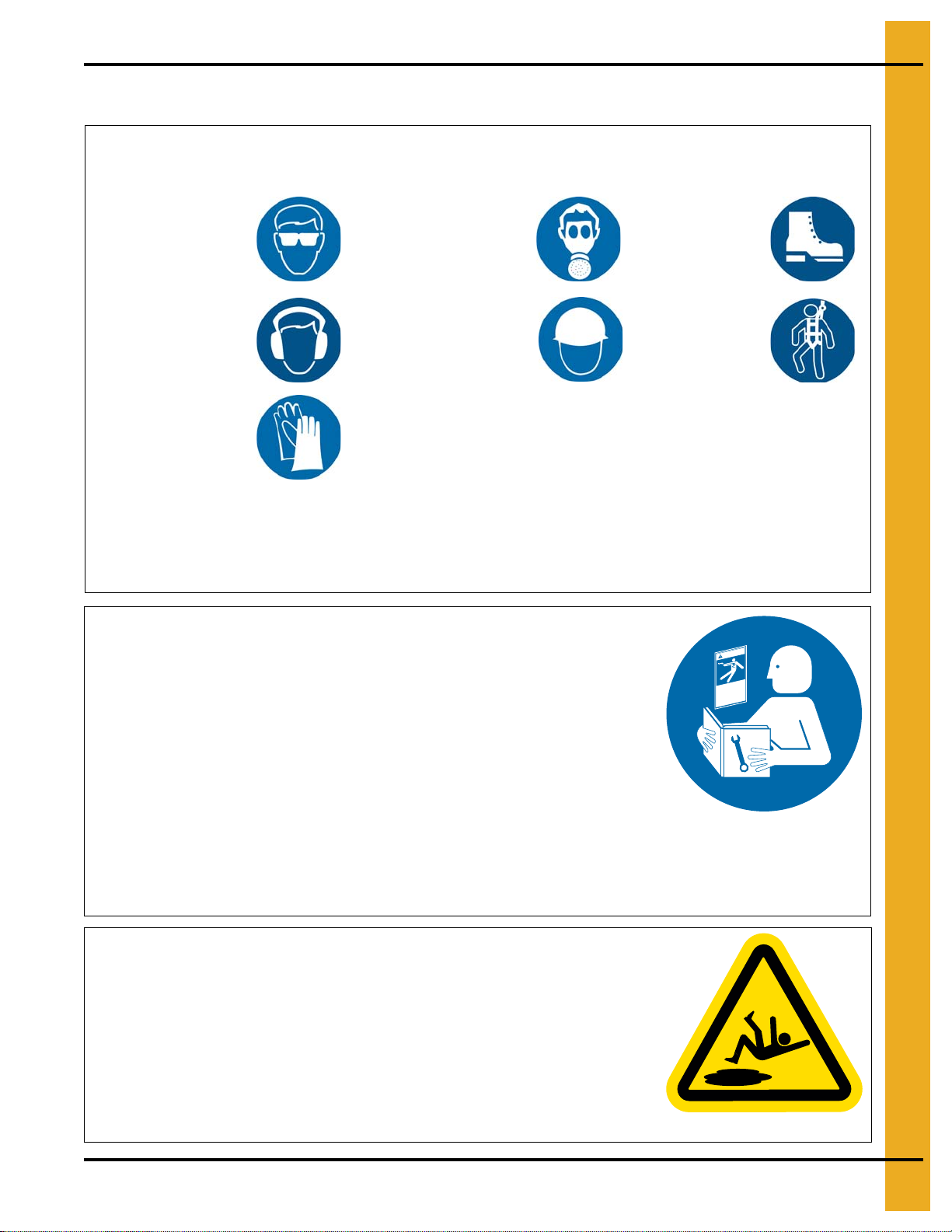
Use Personal Protective Equipment
Eye
Protection
Hearing
Protection
Hand
Protection
Head
Protection
Respiratory
Protection
Foot
Protection
Fall
Protection
• Use appropriate personal protective equipment:
• Wear clothing appropriate to the job.
• Remove all jewelry.
• Tie long hair up and back.
ST-0004-1
Follow Safety Instructions
• Carefully read all safety messages in this manual and
safety signs on your machine. Keep signs in good
condition. Replace missing or damaged safety signs.
Be sure new equipment components and repair parts
include the current safety signs. Replacement safety
signs are available from the manufacturer.
• Learn how to operate the machine and how to use
controls properly. Do not let anyone operate without
instruction.
• If you do not understand any part of this manual or
need assistance, contact your dealer.
ST-0002-1
Maintain Equipment and Work Area
• Understand service procedures before doing work. Keep area
clean and dry.
• Never service equipment while it is operating. Keep hands, feet,
and clothing away from moving parts.
• Keep your equipment in proper working condition. Replace worn
or broken parts immediately.
ST-0003-1
2. Safety
PNEG-1773-EU 42'-135' “X” Series Ladder, Cage and Platform - European Standard 7
Page 8
2. Safety
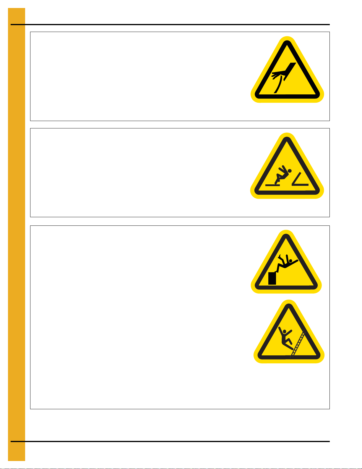
Sharp Edge Hazard
• This product has sharp edges, which can cause serious injury.
• To avoid injury, handle sharp edges with caution and always use
proper protective clothing and equipment.
ST-0036-2
Fall Hazard
• Keep access door closed while on a platform to avoid falls.
• Always use proper personal protective equipment and proper
clothing when using equipment. Failure to follow safety
precautions can result in severe injury or death.
ST-0042-2
Fall Hazard
• Ladders, stairways and platforms are for use by competent and trained
personnel only. Do not allow children or other unauthorized persons to
have access to the equipment.
• Access to the equipment must be restricted by the use of security
fencing and lockable gates.
• Lower sections of ladders must be fitted with a lockable safety gate to
prevent unauthorized access.
• Make sure that hot surfaces have had adequate time to cool before
working on or in the equipment.
• Lock out and tag out power supplies and fuel supplies to all equipment.
• Do not attach lifting equipment to ladders or platforms.
• Do not go outside of the safety rails provided on elevated platforms.
• Do not work at heights during high winds, rain, snow, or ice storms.
ST-0056-1
8 PNEG-1773-EU 42'-135' “X” Series Ladder, Cage and Platform - European Standard
Page 9
2. Safety
Stay Clear of Hoisted Equipment
• Always use proper lifting or hoisting equipment when
assembling or disassembling equipment.
• Do not walk or stand under hoisted equipment.
• Always use sturdy and stable supports when needed for
installation. Not following these safety precautions creates
the risk of falling equipment, which can crush personnel and
cause serious injury or death.
ST-0047-1
Safety Sign-Off Sheet
Below is a sign-off sheet that can be used to verify that all personnel have read and understood the safety
instructions. This sign-off sheet is provided for your convenience and personal record keeping.
Date Employee Name Supervisor Name
PNEG-1773-EU 42'-135' “X” Series Ladder, Cage and Platform - European Standard 9
ST-0007
Page 10

2. Safety
Proper Storage of Grain Bin/Silo Materials Prior to Construction
Wet storage stain (rust) will develop when closely packed bundles of galvanized material, such as sidewall
and roof sheets, have moisture present. Inspect roof and sidewall bundles on arrival for any moisture. If
moisture is present, it must not be allowed to remain between the sheets. Separate the sheets or panels
immediately and wipe them down. Spray with a light oil or diesel fuel.
If possible, sidewall bundles, roof sheets and other closely packed galvanized materials should be stored
in a dry, climate controlled building. If outdoor storage is unavoidable, the materials should be stored so
that they are raised above the ground and vegetation. Any stacking and spacing materials should not be
corrosive or wet. Be sure to protect materials from the weather, but permit air movement around the
bundles if possible.
Storing roof bundles and sidewall sheets at a slight incline can also help minimize the presence of
moisture. Storing the bundles with the center of the dome up (like an arch) is one option for minimizing
moisture during storage. Sidewall bundles can also be stored on edge but must be secured so that they
do not fall over and cause injury.
If “white rust” or “wet storage stain” occurs, contact the manufacturer immediately about ways to minimize
the adverse effect upon the galvanized coating.
10 PNEG-1773-EU 42'-135' “X” Series Ladder, Cage and Platform - European Standard
Page 11
3. Decals
The safety decals on your equipment are safety indicators which must be carefully read and understood
by all personnel involved in the installation, operation, service and maintenance of the equipment.
To replace a damaged of missing decal, contact us to receive a free replacement.
GSI Decals
1004 E. Illinois St.
Assumption, IL. 62510
Phone: 1-217-226-4421
Location Decal # Decals Description
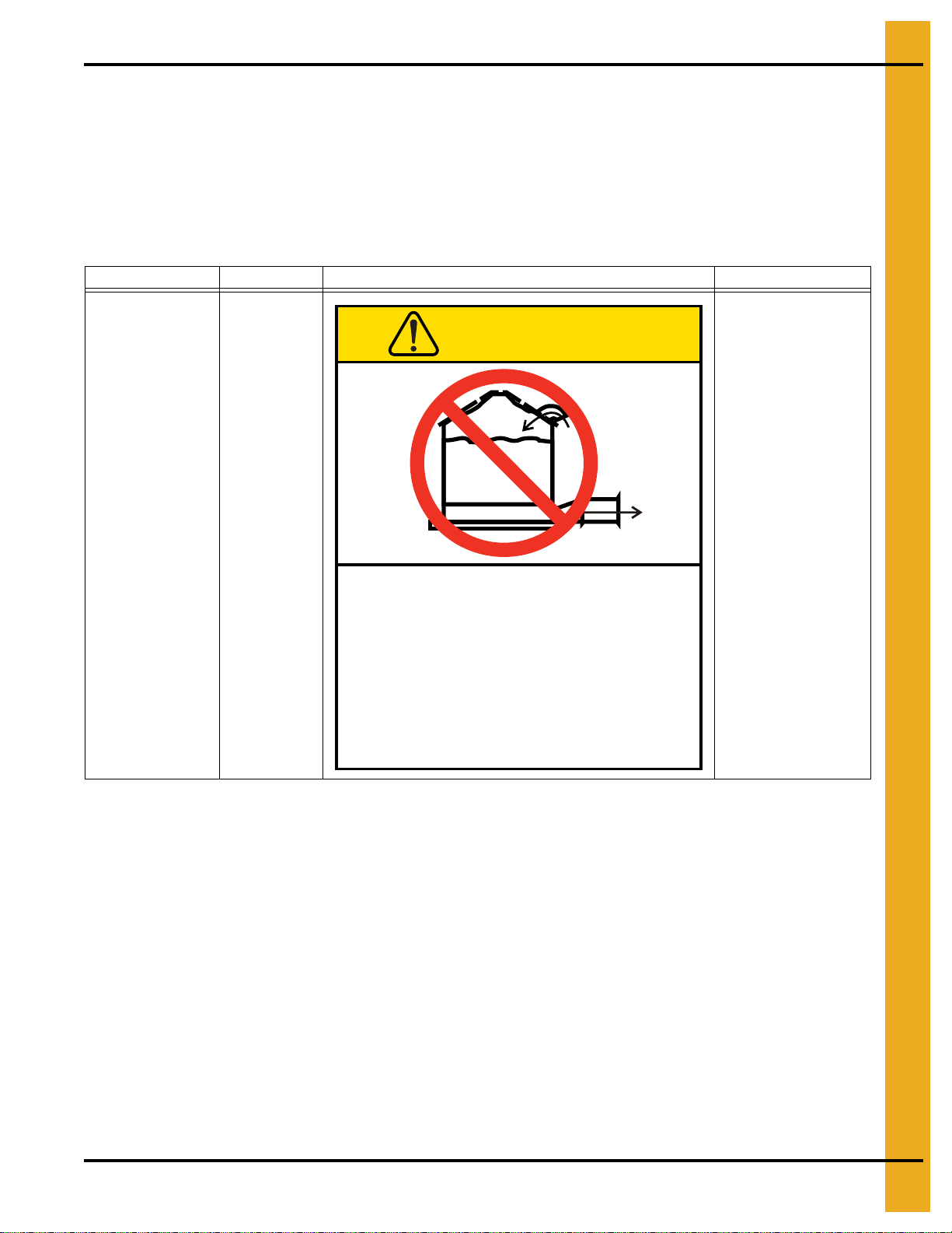
CAUTION
Located next to
aeration system.
DC-969
Excessive vacuum (or pressure) may
damage roof. Use positive aeration
system. Make sure all roof vents are
open and unobstructed. Start roof
fans when supply fans are started.
Do not operate when conditions exist
that may cause roof vent icing.
GSI Group, Inc. 217-226-4421
DC-969
Caution Vacuum
Pressure
PNEG-1773-EU 42'-135' “X” Series Ladder, Cage and Platform - European Standard 11
Page 12
3. Decals
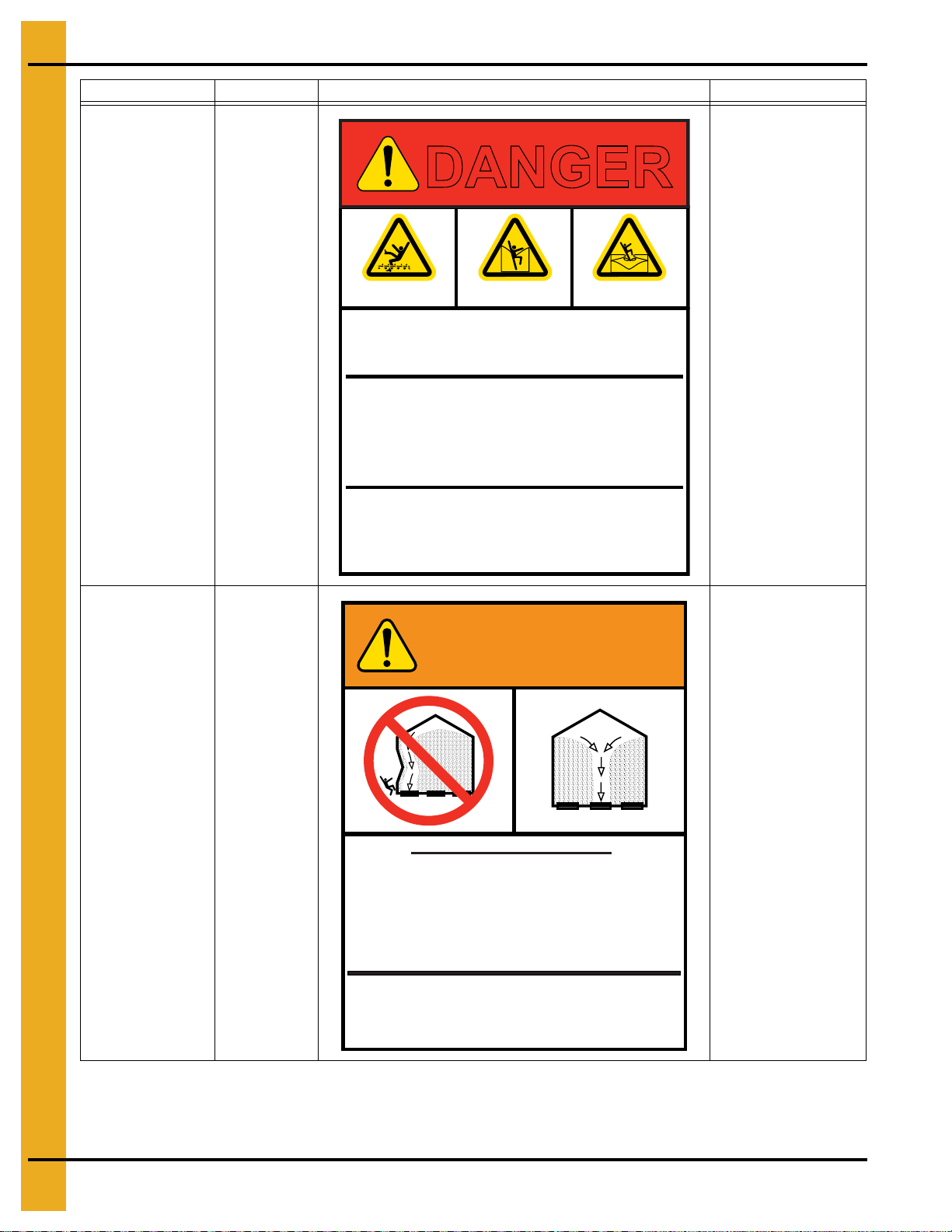
Rotating flighting will
kill or dismember.
Flowing material will
trap and suffocate.
Crusted material will
collapse and suffocate.
DANGER
Keep clear of all augers.
DO NOT ENTER this bin!
If you must enter the bin:
1. Shut off and lock out all power.
2. Use a safety harness and safety line.
3. Station another person outside the bin.
4. Avoid the center of the bin.
5. Wear proper breathing equipment or respirator.
Failure to heed these
warnings will result in
serious injury or death.
DC-GBC-1A
GSI GROUP, INC. 217-226-4421
Location Decal # Decals Description
On bin door
covers
DC-GBC-1A
Danger Keep Clear
of Augers
WARNING
On bin door
covers
DC-GBC-2A
UNLOADING INSTRUCTIONS:
1. Use CENTER FLOOR OUTLET ONLY until NO grain
remains above this outlet.
2. Side floor outlets to be used ONLY when above
condition is satisfied.
3. Lock all side floor outlets to avoid accidental
premature use.
4. See manufacturers instructions for proper use of
factory supplied sidedraw (wall) discharge systems.
Failure to heed these warnings
could result in serious injury, death,
structural damage or collapse of tank.
GSI GROUP, INC. 217-226-4421
DC-GBC-2A
Warning Unload
Instructions
12 PNEG-1773-EU 42'-135' “X” Series Ladder, Cage and Platform - European Standard
Page 13

72'-135' Ladder Eave Platform
Assembly Instructions
PNEG-1773-EU 42'-135' “X” Series Ladder, Cage and Platform - European Standard 13
Page 14
4. Assembly Instructions
72'-135' Ladder Eave Platform Assembly
Ladder Eave Platform Package
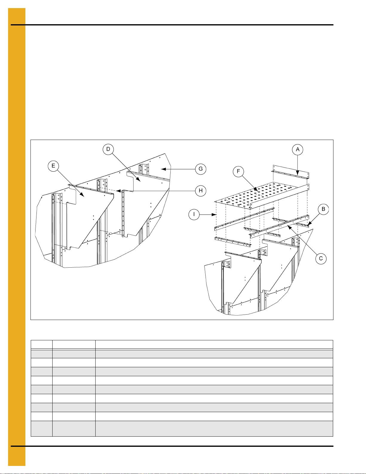
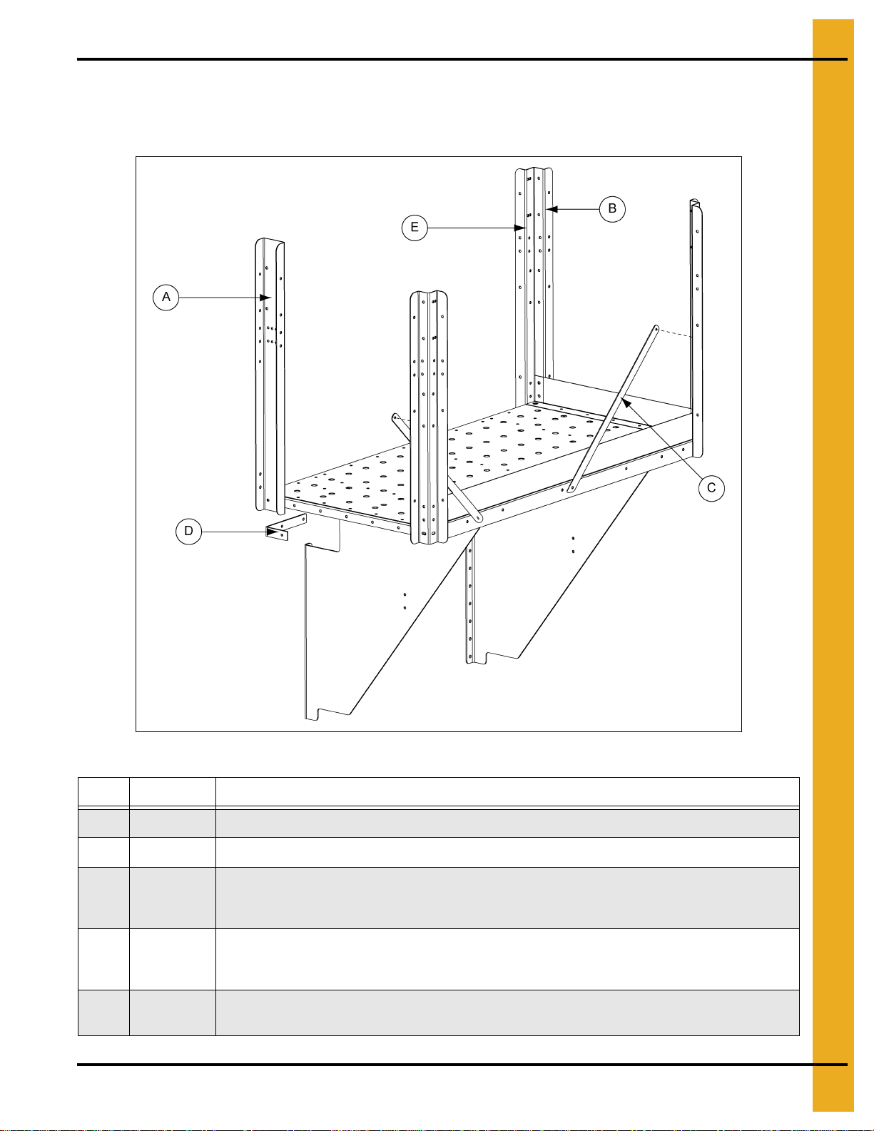
1. Figure 4A shows the assembly of the platform supports. Use 5/16" hardware at all the connection
points. (Platform floor will have to be attached at the same time as support angles.)
NOTE: When installing the top wind ring, do NOT use the top set of holes in the stiffener.
2. Figure 4A shows the assembly of the platform floor system. This must all be assembled at the same
time using 5/16" hardware.
NOTE: Leave all hardware loose until completely assembled.
3. Left platform bracket must line up with stiffener, roof rib and rafter or beam if present in roof.
Figure 4A
Ref # Part # Description
A STX-0014 Platform Toe Plate
B STX-0011 Platform Short Angle (3)
C STX-0081 “X” Series Platform Long Angle (2)
D STX-0082 “X” Series Platform Bracket - Right
E STX-0009 “X” Series Platform Bracket - Left
F STX-0080 Single Piece Platform Floor
G Place brackets in top sidewall ring
H Attach at stiffener to sidewall connection. See note above about wind rings.
I
14 PNEG-1773-EU 42'-135' “X” Series Ladder, Cage and Platform - European Standard
Use 5/16"-18 x 3/4" truss bolt (S-10267) and 5/16"-18 flange nut (S-10268) to attach platform
floor and all substructure.
Page 15
4. Assembly Instructions
Platform and Safety Cage Bar
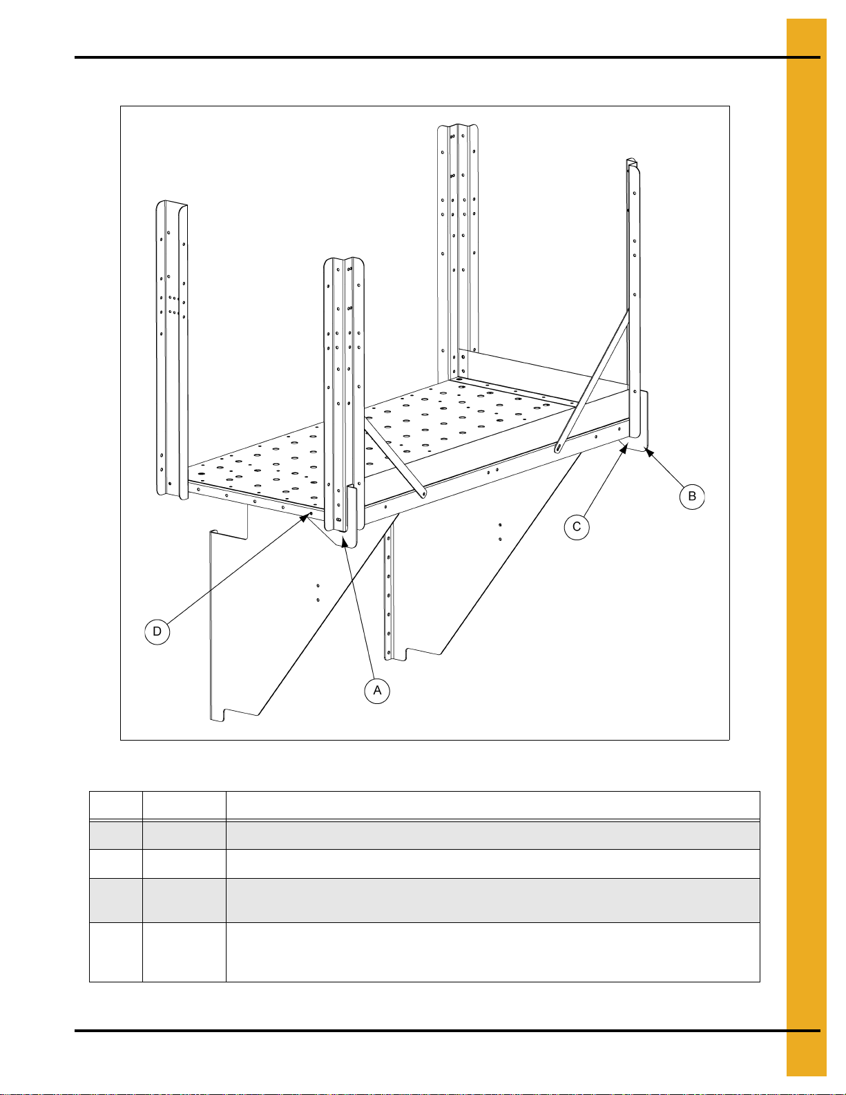
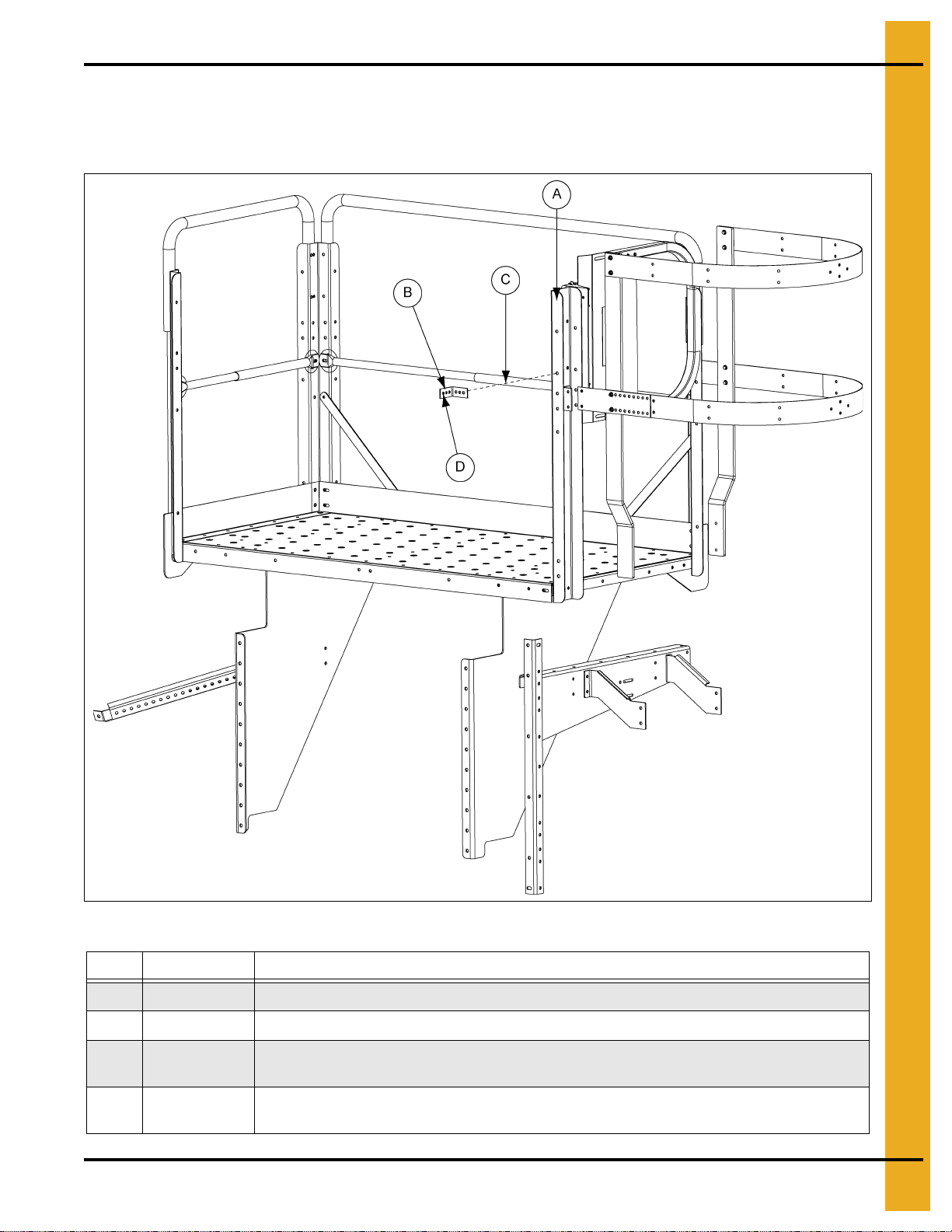
4. Figure 4B shows the assembly of the platform post and post supports. This must all be assembled
at the same time using 5/16" hardware.
Figure 4B
Ref # Part # Description
A STX-0076 Eave Platform Corner Post
B STX-0015 Platform Corner Post. Three (3) per 72'-135' eave platform.
24" Safety Cage Bar. Two (2) per 72'-135' eave platform. Attach using 5/16"-18 x 1" flange bolt
C LDR-5171
D LDR-5205
E
(S-10260) and 5/16"-18 flange nut (S-10268). The end that mounts to the platform angle will be
outside of the toe kick. The end that mounts to the post will be inside of the toe kick plate.
Eave Platform Post Support. One piece assembled under the platform to reinforce the
platform corner. This piece mounts to both the platform short angle and the platform long
angle. Attach using 5/16"-18 x 1" flange bolt (S-10260) and 5/16"-18 flange nut (S-10268).
Attach all handrail posts to platform using 5/16"-18 x 1" flange bolt (S-10260) and 5/16"-18
flange nut (S-10268).
PNEG-1773-EU 42'-135' “X” Series Ladder, Cage and Platform - European Standard 15
Page 16

4. Assembly Instructions
Platform and Wall Brace
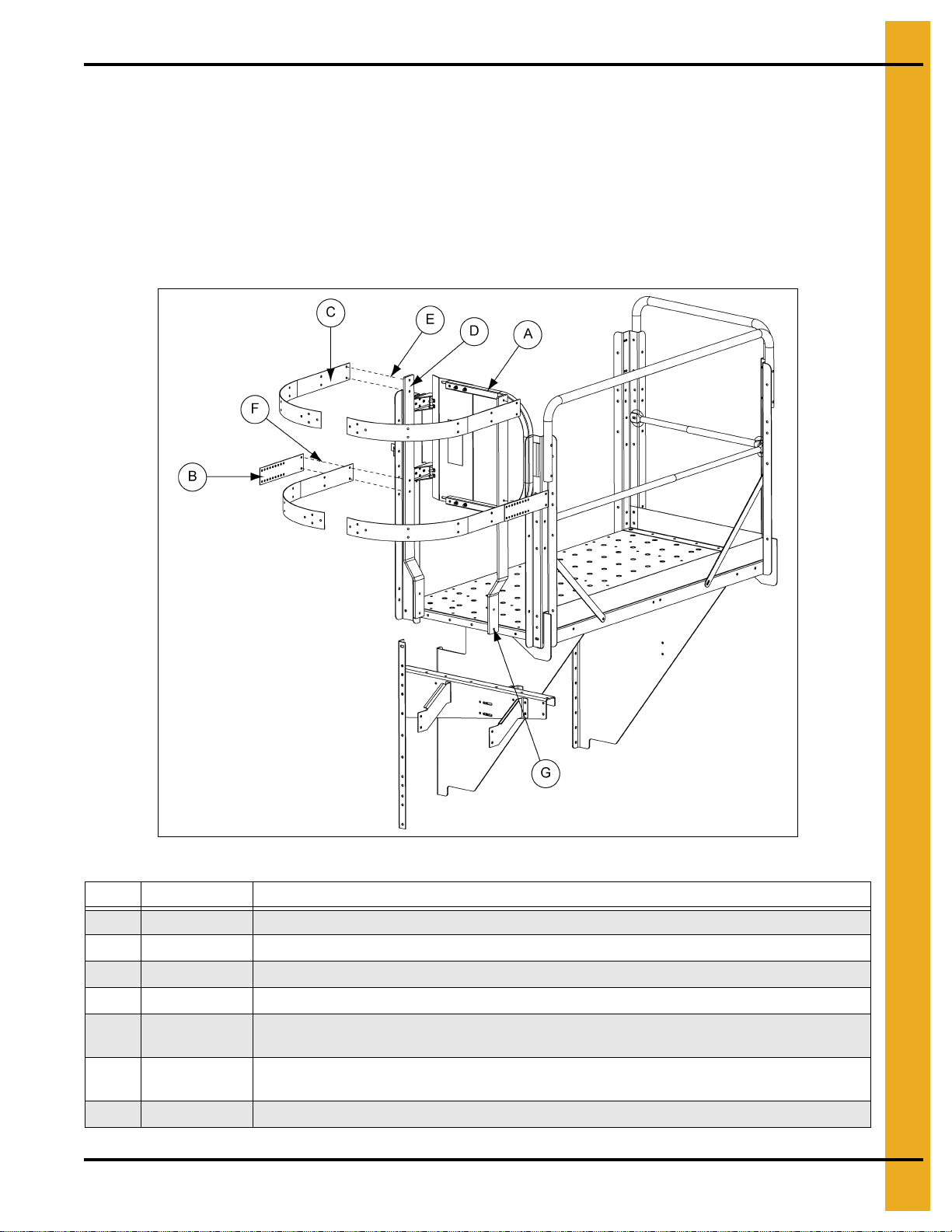
5. Assemble the eave platform wall braces to the platform support and sidewall using 5/16" hardware.
(See Figure 4C below and Figure 4D on Page 17.)
Figure 4C
Ref # Description
Attach eave platform wall bracket to “X” series platform bracket using 5/16"-18 x 1" flange bolt
A
(S-10260) and 5/16"-18 flange nut (S-10268). Attach at sidewall using 5/16"-18 x 1" flange bolt
(S-10260) and 5/16"-18 flange nut (S-10268). Wall brace should be as flat to sidewall as possible.
Eave Platform Wall Brace (LDR-5206). Two (2) pieces bo lted back to back. Length of bolted brace
B
adjusted based on diameter to tank.
16 PNEG-1773-EU 42'-135' “X” Series Ladder, Cage and Platform - European Standard
Page 17
Platform and Wall Brace (Continued)
4. Assembly Instructions
Figure 4D
Ref # Part # Description
A STX-0323 “X” Series Eave Platform Left Outer and Inner Right Post Brace (N/S)
B STX-0324 “X” Series Eave Platform Right Outer Post Brace
C
D
Attach platform post brace using 5/16"-18 x 1" flange bolt (S-10260) and 5/16"-18
flange nut (S-10268).
Post braces attach to both the platform short angle and the platform corner post.
The post brace sits inside of the platform short angle and on the outer side of the
platform corner post.
PNEG-1773-EU 42'-135' “X” Series Ladder, Cage and Platform - European Standard 17
Page 18
4. Assembly Instructions
Platform and Handrail Package
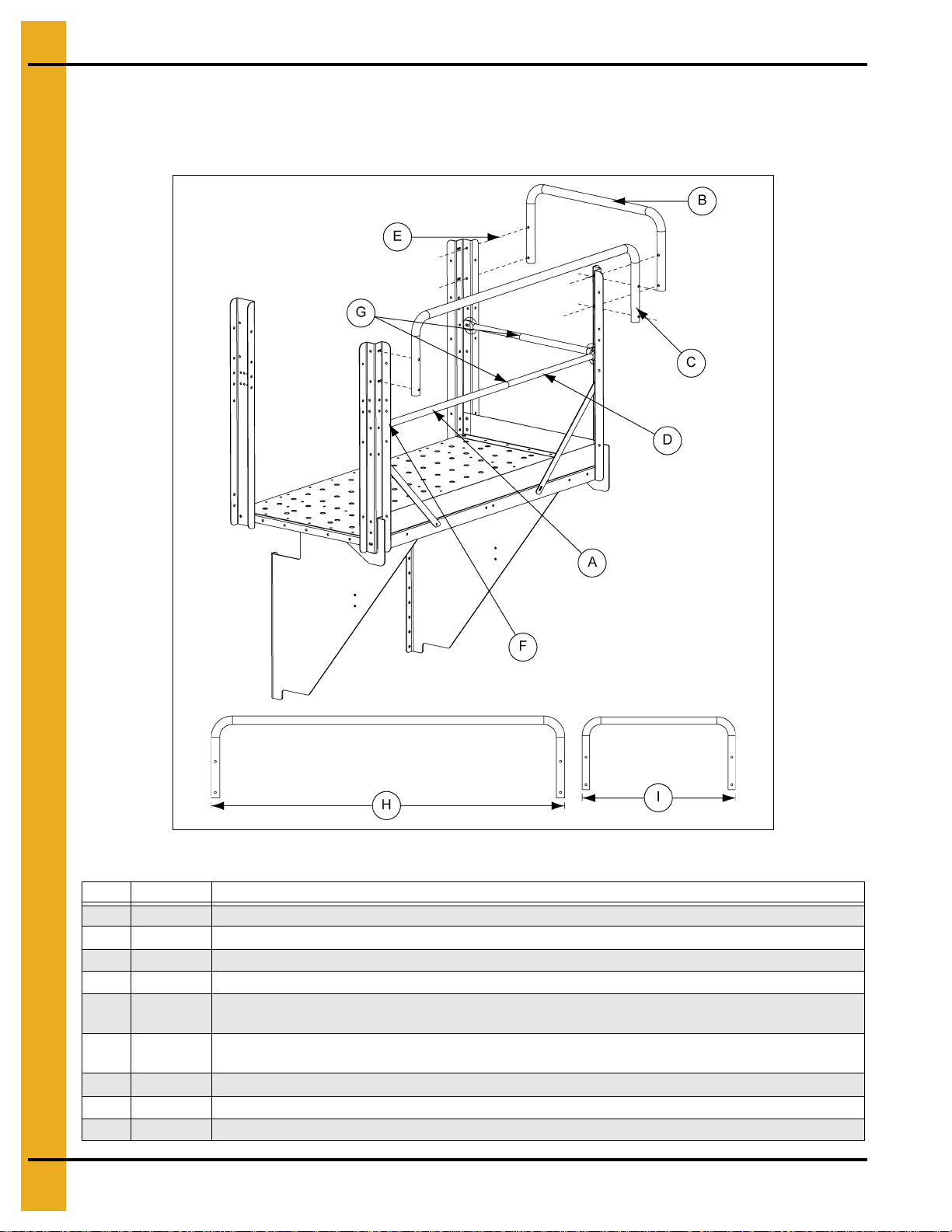
6. Figure 4E shows the assembly of the platform handrails. These must also be attached using
5/16" hardware.
Figure 4E
Ref # Part # Description
A LDR-4087 Large Intermediate Handrail (2). Field cut to fit.
B STX-0038 Platform Handrail Short
C STX-0075 Eave Platform Top Rail - Long
D LDR-4088 Small Intermediate Handrail (2). Field cut to fit.
E
F
G Place self-drilling screw on bottom at overlap.
H STX-0075 62-3/4" - Eave Platform Top Rail - Long
I STX-0038 30-3/4" - Platform Handrail - Short
Attach upper handrails to platform posts using 5/16" x 2" bolt (S-7877) and 5/16"-18
flange nut (S-10268).
Attach intermediate handrails to platform posts using 5/16"-18 x 1" flange bolt (S-10260) and
5/16"-18 flange nut (S-10268).
18 PNEG-1773-EU 42'-135' “X” Series Ladder, Cage and Platform - European Standard
Page 19
4. Assembly Instructions
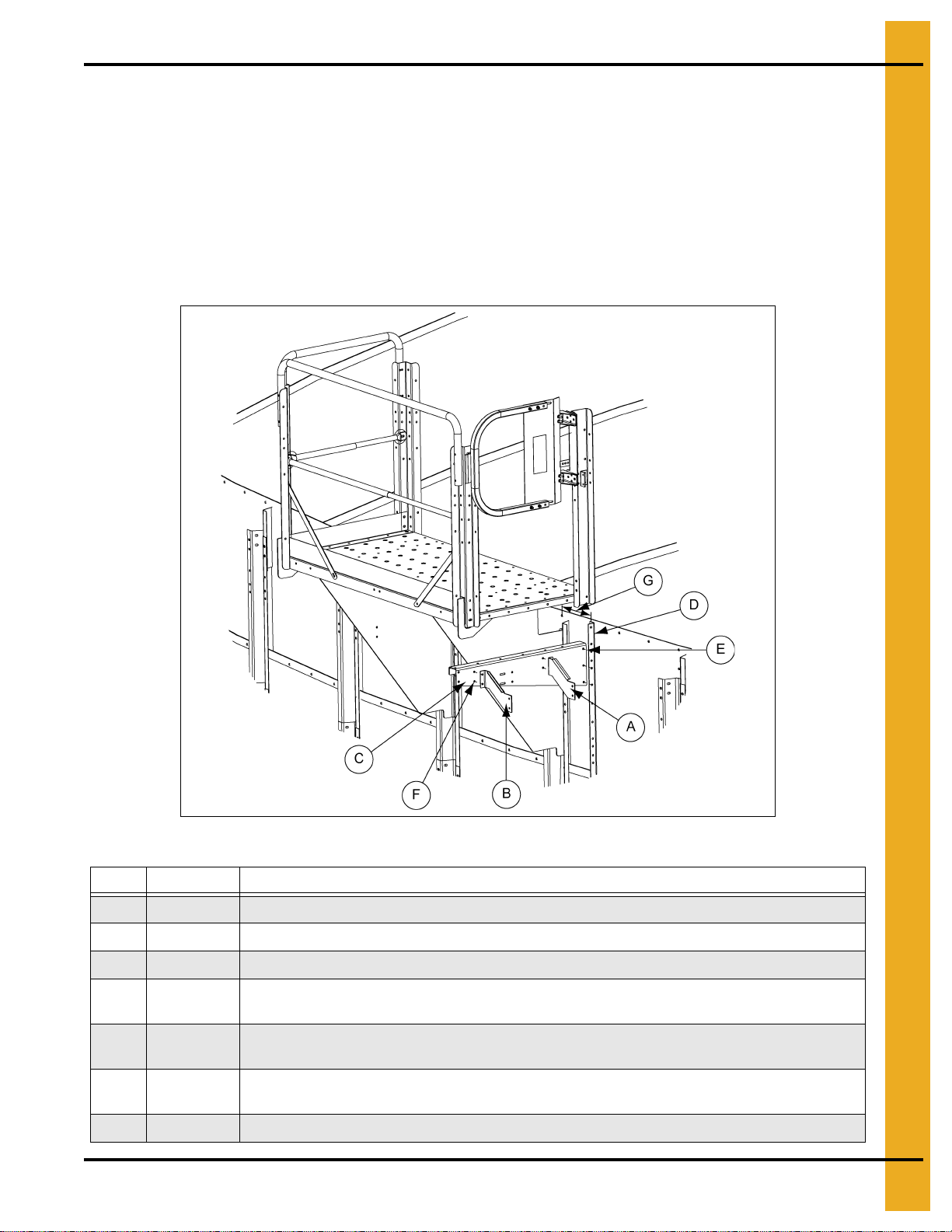
Platform and Swing Gate Package
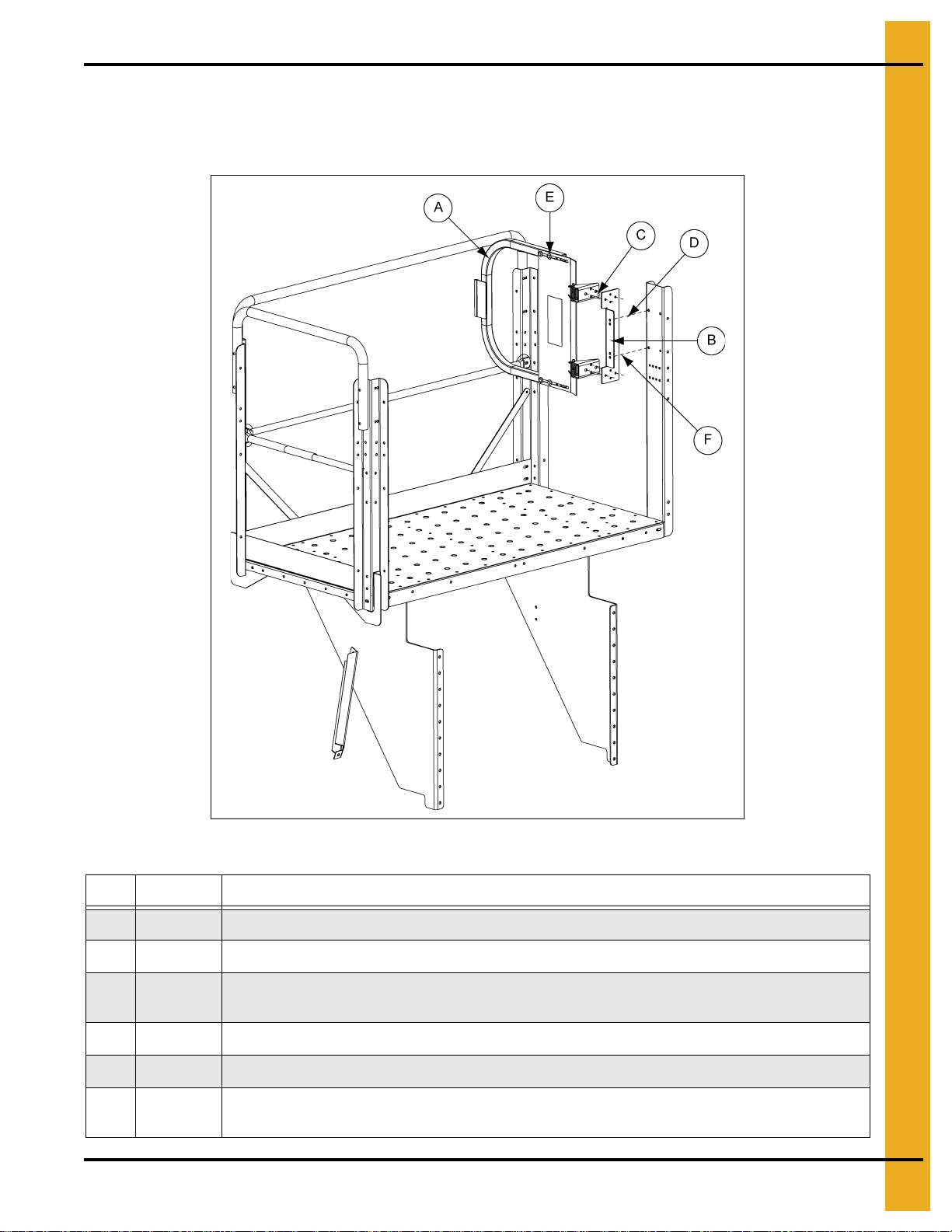
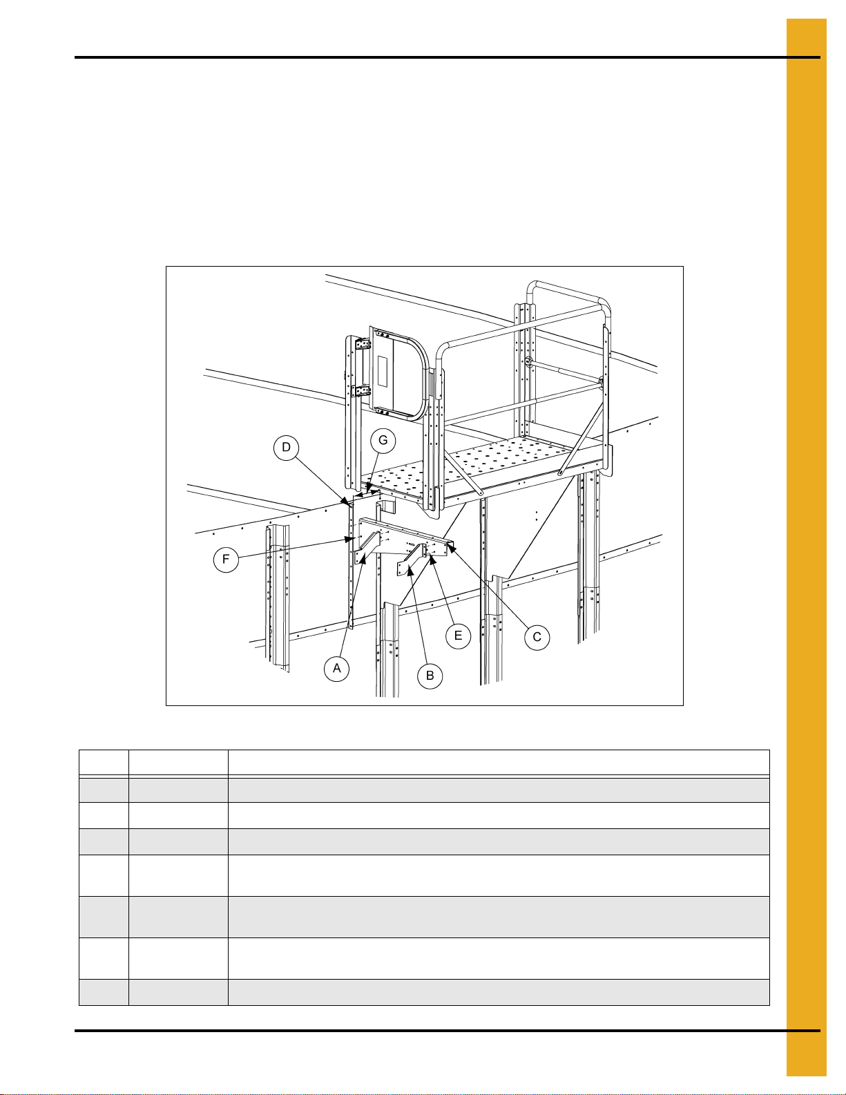
7. Attach the platform gate bracket to the gate before attaching it to the inside platform post using
5/16" hardware. (See Figure 4F below and Figure 4G on Page 20.)
Figure 4F
Ref # Part # Description
A LDR-5218 Ladder Safety Gate
B LDR-5185 Intermediate Platform Gate Bracket
C
D When mounting the intermediate platform gate bracket, use the top and bottom holes.
E Swing gate should swing inward to the platform.
F
Attach safety gate assembly to intermediate platform gate bracket using 5/16"-18 x 1" flange bolt
(S-10260) and 5/16"-18 flange nut (S-10268).
Attach intermediate platform gate bracket to platform corner post using 5/16"-18 x 1" flange bolt
(S-10260) and 5/16"-18 flange nut (S-10268).
PNEG-1773-EU 42'-135' “X” Series Ladder, Cage and Platform - European Standard 19
Page 20
4. Assembly Instructions
Platform and Swing Gate Package (Continued)
Figure 4G
Ref # Description
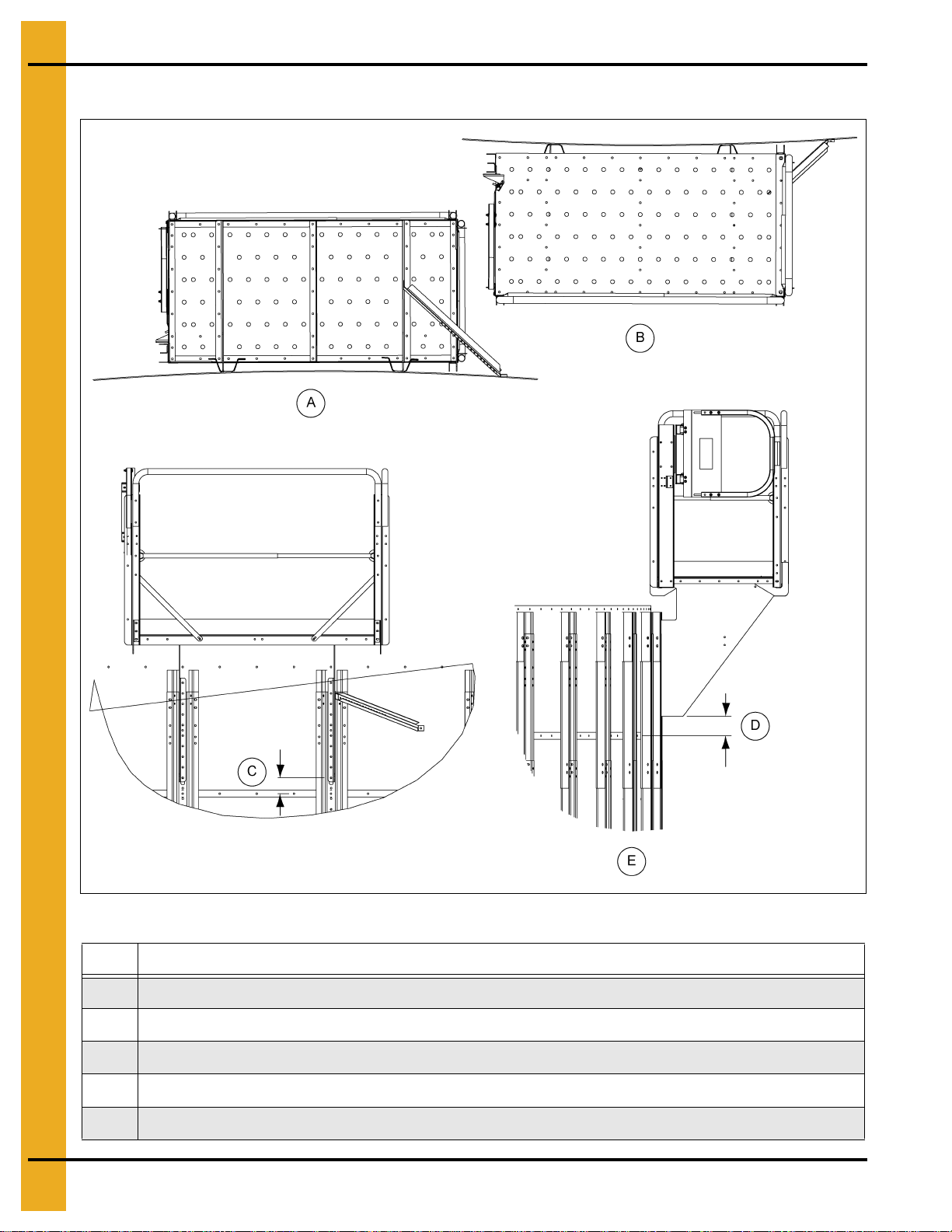
A Bottom view of assembled eave platform for 72'-135' and its relation to the stiffeners and sidewall.
B Top view of assembled eave platform for 72'-135' and its relation to the stiffeners and sidewall.
C Distance between the bottom of the platform wall bracket and the horizontal seam is approximately 4".
D Distance between the platform wall bracket notch and the horizontal seam is approximately 4.920".
E Left hand side view of assembled eave platform for 72'-135' and its relation to the stiffeners and sidewall.
20 PNEG-1773-EU 42'-135' “X” Series Ladder, Cage and Platform - European Standard
Page 21
4. Assembly Instructions
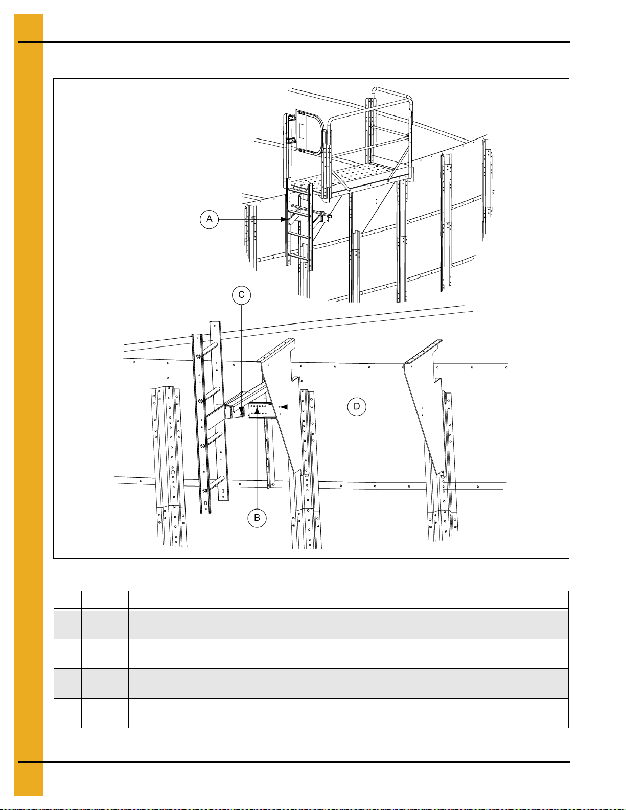
Platform Ladder Bracket Package - Left Hand Side Assembly
8. Attach the wall angle to the sidewall sheet using the hole 9-3/8" from the stiffener hole pattern with
3/8" hardware. Assemble the wall bracket to the wall angle with 3/8" hardware and tighten.
(See Figure 4H below and Figure 4I on Page 22.)
Attach left and right intermediate platform ladder bracket to the wall bracket and platform support with
5/16" hardware.
NOTE: Do not force the wall bracket in or out.
Assemble the ladder and ladder brackets to the wall bracket using 5/16" hardware. The top ladder
rung must be level with the platform floor.
Figure 4H
Ref # Part # Description
A LDR-5178 Intermediate Platform Ladder Bracket - Left
B LDR-5177 Intermediate Platform Ladder Bracket - Right
C LDR-5174 Intermediate Platform Bracket - Left
D
E
F
G 9-3/8"
PNEG-1773-EU 42'-135' “X” Series Ladder, Cage and Platform - European Standard 21
Attach ladder sidewall angle (LDR-5168) to bin wall here 9-3/8" from platform wall bracket.
Use 5/16"-18 x 1" flange bolt (S-10260) and 5/16"-18 flange nut (S-10268).
Attach intermediate platform ladder to platform wall bracket using 5/16"-18 x 1" flange bolt
(S-10260) and 5/16"-18 flange nut (S-10268).
Attach ladder sidewall angle (LDR-5168) to platform wall bracket using 3/8-16" x 1"
flange bolt (S-7485) and 3/8"-16 flange nut (S-9426).
Page 22
4. Assembly Instructions
Platform Ladder Bracket Package - Left Hand Side Assembly (Continued)
Figure 4I
Ref # Part # Description
A 4FOOTRF
B LDR-5159
C
D
The Figure 4I shown with platform pan, post, handrails and safety gate hidden.
4' Roll Formed Ladder. Attach 4' roll formed ladder to intermediate platform ladder bracket
using 5/16"-18 x 1" flange bolt (S-10260) and 5/16"-18 flange nut (S-10268).
Eave Platform Ladder Bracket. Two (2) parts bolted back to back. Length of bolted parts
dependent on bin diameter.
Attach ladder stand off to wall bracket using 5/16"-18 x 1" flange bolt (S-10260) and 5/16"-18
flange nut (S-10268).
Attach ladder stand off to platform bracket using 5/16"-18 x 1" flange bolt (S-10260) and 5/16"-18
flange nut (S-10268).
22 PNEG-1773-EU 42'-135' “X” Series Ladder, Cage and Platform - European Standard
Page 23
4. Assembly Instructions
Platform Ladder Bracket Package - Right Hand Side Assembly
9. Attach the wall angle to the sidewall sheet using the hole 9-3/8" from the stiffener hole pattern with
3/8" hardware. Assemble the wall bracket to the wall angle with 3/8" hardware and tighten.
(See Figure 4J below and Figure 4K on Page 24.)
Attach left and right intermediate platform ladder bracket to the wall bracket and platform support with
5/16" hardware.
NOTE: Do not force the wall bracket in or out.
Assemble the ladder and ladder brackets to the wall bracket using 5/16" hardware. The top ladder
rung must be level with the platform floor.
Figure 4J
Ref # Part # Description
A LDR-5178 Intermediate Platform Ladder Bracket - Left
B LDR-5177 Intermediate Platform Ladder Bracket - Right
C LDR-5173 Intermediate Platform Bracket - Right
D
E
F
G 9-3/8"
PNEG-1773-EU 42'-135' “X” Series Ladder, Cage and Platform - European Standard 23
Attach ladder sidewall angle (LDR-5168) to bin wall here 9-3/8" from platform wall bracket.
Use 5/16"-18 x 1" flange bolt (S-10260) and 5/16"-18 flange nut (S-10268).
Attach ladder sidewall angle (LDR-5168) to platform wall bracket using 3/8-16" x 1" flange bolt
(S-7485) and 3/8"-16 flange nut (S-9426).
Attach intermediate platform ladder to platform wall bracket using 5/16"-18 x 1" flange bolt
(S-10260) and 5/16"-18 flange nut (S-10268).
Page 24
4. Assembly Instructions
Platform Ladder Bracket Package - Right Hand Side Assembly (Continued)
Figure 4K
Ref # Part # Description
A 4FOOTRF
B LDR-5159
C
D
The Figure 4K shown without platform pan, post, handrail and safety gate.
4' Roll Formed Ladder. Attach 4' roll formed ladder to intermediate platform ladder bracket
using 5/16"-18 x 1" flange bolt (S-10260) and 5/16"-18 flange nut (S-10268).
Eave Platform Ladder Bracket. Two (2) parts bolted back to back. Length of bolted parts
dependent on bin diameter.
Attach ladder stand off to platform bracket using 5/16"-18 x 1" flange bolt (S-10260) and 5/16"-18
flange nut (S-10268).
Attach ladder stand off to wall bracket using 5/16"-18 x 1" flange bolt (S-10260) and 5/16"-18
flange nut (S-10268).
24 PNEG-1773-EU 42'-135' “X” Series Ladder, Cage and Platform - European Standard
Page 25
4. Assembly Instructions
Platform and Safety Cage Package
10. Attach the ladder flare to the ladder using 5/16" hardware. You must drill the bottom hole through the
ladder and use 5/16" hardware. (See Figure 4L.)
11. Attach the cage hoops and cage splice brackets to the ladder flares and platform posts. This must
all be assembled at the same time using 5/16" hardware.
NOTE: Be sure the ladder flares are vertical and parallel to the platform posts by adjusting the
splice brackets. The ladder will NOT be square to the p latform due to the radius of the
bin. The side closest to the bin wall will be closer to the platform.
Figure 4L
Ref # Part # Description
A LDR-5218 Ladder Safety Gate
B LDR-5167 Safety Cage Hoop Splice (2)
C LDR-5164 Safety Cage Hoop - Standard (4)
D LDR-5493 Formed Ladder Flare (2)
E
F
G This hole must be drilled through ladder on right and left sides.
PNEG-1773-EU 42'-135' “X” Series Ladder, Cage and Platform - European Standard 25
Attach safety cage hoop to formed ladder flare using 5/16"-18 x 1" flange bolt (S-10260)
and 5/16"-18 flange nut (S-10268).
Attach safety cage hoop splice to safety cage hoop using 5/16"-18 x 1" flange bolt
(S-10260) and 5/16"-18 flange nut (S-10268).
Page 26

4. Assembly Instructions
Platform and Safety Cage Splice Bracket
12. Attach the cage splice bracket to the post and cage splice using 5/16" hardware. (See Figure 4M.)
Figure 4M
Ref # Part # Description
A LDR-5204 Safety Cage Splice Bracket
B LDR-5167 Safety Cage Hoop Splice
C
D
Attach safety cage splice bracket to handrail post using 5/16"-18 x 1" flange bolt
(S-10260) and 5/16"-18 flange nut (S-10268).
Attach safety cage hoop splice to platform post or safety cage splice bracket.
Mounting location is dependent on diameter of tank.
26 PNEG-1773-EU 42'-135' “X” Series Ladder, Cage and Platform - European Standard
Page 27
Platform Inside Post Bracket
4. Assembly Instructions
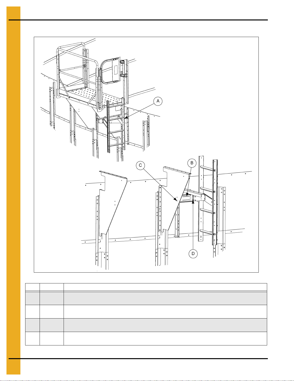
13. Attach the post bracket to the inside post and bottom stair post using 5/16" hardware.
NOTE: Continue to Page 48 to see remaining ladder and cage layout.
(See Figure 4N.)
Figure 4N
Ref # Part # Description
A STX-0076 Eave Platform Corner Post
B LDR-5207 Eave Platform Inside Post Bracket
C
D
PNEG-1773-EU 42'-135' “X” Series Ladder, Cage and Platform - European Standard 27
Attach eave platform inside post bracket to platform corner post using 5/16"-18 x 1"
flange bolt (S-10260) and 5/16"-18 flange nut (S-10268).
Field drill holes in roof stair post. Attach using 5/16"-18 x 1" flange bolt (S-10260) and
5/16"-18 flange nut (S-10268).
Page 28

NOTES
28 PNEG-1773-EU 42'-135' “X” Series Ladder, Cage and Platform - European Standard
Page 29

72'-135' Ladder Only Eave
Platform Assembly Instructions
PNEG-1773-EU 42'-135' “X” Series Ladder, Cage and Platform - European Standard 29
Page 30

4. Assembly Instructions
Special Order Package Only
72'-135' Ladder Only Eave Platform Package with Manway Guard
NOTE: Used when there are no roof stairs.
1. Attach ladder/eave platform handrail bracket (LDR-5304) and ladder/eave platform kick plate splice
plate (LDR-5305) to eave handrail post (STX-0076) using 5/16" hardware. LDR-5207 will not be used
in this package. (See Figure 4O below and Figure 4P on Page 31.)
Figure 4O
Ref # Part # Description
A LDR-5304 Ladder/Eave Platform Handrail Bracket (2)
B LDR-5305 Ladder/Eave Platform Kick Plate Splice Plate
Attach ladder/eave platform handrail bracket (LDR-5304) and ladder/eave platform kick plate
C
30 PNEG-1773-EU 42'-135' “X” Series Ladder, Cage and Platform - European Standard
splice plate (LDR-5305) to handrail post using 5/16"-18 x 1" flange bolt (S-10260) and 5/16"-18
flange nut (S-10268).
Page 31

4. Assembly Instructions
NOTE: The parts pointed out on this page are listed on Page 32.
72'-135' Ladder Only Eave Platform Package with Manway
Guard (Continued)
PNEG-1773-EU 42'-135' “X” Series Ladder, Cage and Platform - European Standard 31
Figure 4P
Page 32

4. Assembly Instructions
72'-135' Ladder Only Eave Platform Package with Manway
Guard (Continued)
Ref # Part # Description
A STX-0038 Platform Handrail Short
B STX-0212 Middle Handrail Support Post
C STX-0045 Stair to Roof Panel Angle Attach (2)
D LDR-5302 Sidedraw Platform Handrail Short
E STX-0043 Manway Incline Rail (2)
F STX-0044 Manway Corner Post (2)
G LDR-4088 Small Intermediate Handrail (4). Field cut to fit.
H STX-0057 Manway Handrail Grab Bar (2). Attach using bin bolt and flange nut.
I STX-0215 Roof Stair Toe Plate
J LDR-4087 Large Intermediate Handrail (4). Field cut to fit.
K Manway
L
M Place self-drilling screw at overlap.
N Attach all upper handrails using 5/16" x 2" bolt (S-7877) and 5/16"-18 flange nut (S-10268).
O
P STX-0038 30-3/4" - Platform Handrail Short
Q LDR-5302 23-7/8" - Sidedraw Platform Handrail Short
R STX-0043 40-3/4" - Manway Incline Rail
Attach intermediate handrails using 5/16"-18 x 1" flange bolt (S-10260) and 5/16"-18
flange nut (S-10268).
Attach post and bracket using 5/16"-18 x 1" flange bolt (S-10260) and 5/16"-18 flange nut
(S-10268).
32 PNEG-1773-EU 42'-135' “X” Series Ladder, Cage and Platform - European Standard
Page 33

42'-60' Ladder Eave Platform
Assembly Instructions
PNEG-1773-EU 42'-135' “X” Series Ladder, Cage and Platform - European Standard 33
Page 34

4. Assembly Instructions
42'-60' Ladder Eave Platform Assembly
Ladder Eave Platform Package
1. Figure 4Q below and Figure 4R on Page 35 shows the assembly of the platform supports. Use
5/16" hardware at all the connection points. (Platform floor will have to be attached at the same time
as support angles.)
NOTE: When installing the top wind ring, do NOT use the top set of holes in the stiffener.
NOTE: Leave all hardware loose until completely assembled.
2. Left platform bracket must be line up with stiffener roof rib and rafter of beam if present
in roof.
Figure 4Q
Ref # Part # Description
A STX-0009 “X” Series Platform Bracket - Left
B STX-0082 “X” Series Platform Bracket - Right
C STX-0135 “X” Series Long Eave Platform Bracket
D Platform brackets mount inside of the stiffeners.
E 48' Shell
34 PNEG-1773-EU 42'-135' “X” Series Ladder, Cage and Platform - European Standard
Page 35

Ladder Eave Platform Package (Continued)
4. Assembly Instructions
Figure 4R
Ref # Part # Description
A STX-0134 Single Piece Long Eave Platform Floor
B STX-0140 “X” Series Eave Platform Floor - Right
C STX-0142 “X” Series Eave Platform Toe Board
D STX-0143 “X” Series Long Eave Platform Splice Angle
E STX-0138 “X” Series Eave Platform Middle Angle (2)
F STX-0136 “X” Series Eave Platform Long Angle (2)
G STX-0011 Platform Short Angle (2)
H STX-0137 “X” Series Long Eave Platform Short Angle (2)
I
Use 5/16"-18 x 3/4" truss bolt (S-10267) and 5/16"-18 flange nut (S-10268) to attach
platform floor and all substruc tu re.
PNEG-1773-EU 42'-135' “X” Series Ladder, Cage and Platform - European Standard 35
Page 36

4. Assembly Instructions
Platform and Safety Cage Bar
3. Figure 4S shows the assembly of the platform post. This must all be assembled at the same time
using 5/16" hardware. NOTE: 24" Safety cage bars are mounted to the inside of the post and the
outside of the platform long angle.
Figure 4S
Ref # Part # Description
A STX-0139 “X” Series Eave Platform Outside Corner Post (2)
B STX-0144 “X” Series Eave Platform Inside Corner Post (2)
C STX-0146 “X” Series Eave Platform Inside Center Post
D STX-0141 “X” Series Eave Platform Outside Center Post
E LDR-5171 24" Safety Cage Bar (4)
F
36 PNEG-1773-EU 42'-135' “X” Series Ladder, Cage and Platform - European Standard
Attach all handrail posts to platform using 5/16"-18 x 1" flange bolt (S-10260) and 5/16"-18
flange nut (S-10268).
Page 37

4. Assembly Instructions
NOTE: The parts pointed out on this page are listed on Page 38.
Platform and Handrail Package
4. Figure 4T shows the assembly of the platform handrails. These must also be attached using
5/16" hardware.
PNEG-1773-EU 42'-135' “X” Series Ladder, Cage and Platform - European Standard 37
Figure 4T
Page 38

4. Assembly Instructions
Platform and Handrail Package (Continued)
Ref # Part # Description
A LDR-4088 Small Intermediate Handrail (2). Field cut to fit.
B LDR-4087 Large Intermediate Handrail (2). Field cut to fit.
C STX-0147 “X” Series Eave Platform Inside Top Rail (2)
D STX-0251 “X” Series Eave Platform Left Front Post Brace
E STX-0038 Platform Handrail Short
F STX-0145 “X” Series Eave Platform Top Rail - Long (2)
G STX-0252 “X” Series Eave Platform Front Right Post Brace
H STX-0253 “X” Series Eave Platform Back Right Post Brace (N/S)
I STX-0151 “X” Series Eave Platform Center Post Brace
J
K
L STX-0147 12-3/4" - “X” Series Eave Platform Inside Top Rail
M STX-0145 57.813" - “X” Series Eave Platform Top Rail - Long
N STX-0038 30-3/4" - Platform Handrail Short
Attach upper handrails to platform posts using 5/16" x 2" bolt (S-7877) and 5/16"-18
flange nut (S-10268).
Attach intermediate handrails to platform posts using 5/16"-18 x 1" flange bolt
(S-10260) and 5/16"-18 flange nut (S-10268).
38 PNEG-1773-EU 42'-135' “X” Series Ladder, Cage and Platform - European Standard
Page 39

4. Assembly Instructions
Platform and Swing Gate Package
5. Attach the platform gate bracket to the gate before attaching it to the inside platform post using
5/16" hardware. (See Figure 4U.)
Figure 4U
Ref # Part # Description
A LDR-5218 Ladder Safety Gate
B STX-0139 “X” Series Eave Platform Outside Corner Post
C LDR-5185 Intermediate Platform Gate Bracket
D
PNEG-1773-EU 42'-135' “X” Series Ladder, Cage and Platform - European Standard 39
Attach safety gate to platform post using 5/16"-18 x 1" flange bolt (S-10260) and 5/16"-18
flange nut (S-10268).
Page 40

4. Assembly Instructions
Platform Ladder Bracket Package
6. Attach the wall angle to the sidewall sheet using the hole 9-3/8" from the stiffener hole pattern with
3/8" hardware. Assemble the wall bracket to the wall angle with 3/8" hardware and tighten.
(See Figure 4V below and Figure 4W on Page 41.)
Attach left and right intermediate platform ladder bracket to the wall bracket and platform support with
5/16" hardware.
NOTE: Do not force the wall bracket in or out.
Assemble the ladder and ladder brackets to the wall bracket using 5/16" hardware. The top ladder
rung must be level with the platform floor.
Figure 4V
Ref # Part # Description
A LDR-5178 Intermediate Platform Ladder Bracket - Left
B LDR-5177 Intermediate Platform Ladder Bracket - Right
C LDR-5174 Intermediate Platform Bracket - Left
D
E
F
G 9-3/8"
40 PNEG-1773-EU 42'-135' “X” Series Ladder, Cage and Platform - European Standard
Attach ladder sidewall angle (LDR-5168) to bin wall here 9-3/8" from platform wall
bracket. Use 5/16"-18 x 1" flange bolt (S-10260) and 5/16"-18 flange nut (S-1 0268).
Attach intermediate platform ladder to platform wall bracket using 5/16"-18 x 1"
flange bolt (S-10260) and 5/16"-18 flange nut (S-10268).
Attach ladder sidewall angle (LDR-5168) to platform wall bracket using 3/8-16" x 1"
flange bolt (S-7485) and 3/8"-16 flange nut (S-9426).
Page 41

Platform Ladder Bracket Package (Continued)
4. Assembly Instructions
Figure 4W
Ref # Part # Description
A 4FOOTRF
B LDR-5159
C
D
4' Roll Formed Ladder. Attach 4' roll formed ladder to intermediate platform ladder bracket using
5/16"-18 x 1" flange bolt (S-10260) and 5/16"-18 flange nut (S-10268).
Eave Platform Ladder Bracket. Two (2) parts bolted back to back. Length of bolted parts
dependent on bin diameter.
Attach ladder stand off to wall bracket using 5/16"-18 x 1" flange bolt (S-10260) and 5/16"-18
flange nut (S-10268).
Attach ladder stand off to platform bracket using 5/16"-18 x 1" flange bolt (S-10260) and 5/16"-18
flange nut (S-10268).
PNEG-1773-EU 42'-135' “X” Series Ladder, Cage and Platform - European Standard 41
Page 42

4. Assembly Instructions
Platform and Safety Cage Package
7. Attach the ladder flare to the ladder using 5/16" hardware. You must drill the bottom hole through the
ladder and use 5/16" hardware. (See Figure 4X.)
8. Attach the cage hoops and cage splice brackets to the ladder flares and platform posts. This must all
be assembled at the same time using 5/16" hardware.
NOTE: Be sure the ladder flares are vertical and parallel to the platform posts by adjusting the
splice brackets. The ladder will NOT be square to the platform due to the radius of the
bin. The side closest to the bin wall will be closer to the platform.
Figure 4X
Ref # Part # Description
A LDR-5218 Ladder Safety Gate
B LDR-5167 Safety Cage Hoop Splice (2)
C LDR-5164 Safety Cage Hoop - Standard (4)
D LDR-5493 Formed Ladder Flare (2)
E
F
G This hole must be drilled through ladder on right and left sides.
42 PNEG-1773-EU 42'-135' “X” Series Ladder, Cage and Platform - European Standard
Attach safety cage hoop to formed flare using 5/16"-18 x 1" flange bolt (S-10260) and
5/16"-18 flange nut (S-10268 ).
Attach safety cage hoop splice to safety cage hoop using 5/16"-18 x 1" flange bolt
(S-10260) and 5/16"-18 flange nut (S-10268).
Page 43

42'-60' Ladder Only Eave
Platform Assembly Instructions
PNEG-1773-EU 42'-135' “X” Series Ladder, Cage and Platform - European Standard 43
Page 44

4. Assembly Instructions
NOTE: The parts pointed out on this page are listed on Page 45.
42'-60' Ladder Only Eave Platform Assembly
Figure 4Y
44 PNEG-1773-EU 42'-135' “X” Series Ladder, Cage and Platform - European Standard
Page 45

4. Assembly Instructions
42'-60' Ladder Only Eave Platform Assembly (Continued)
Ref # Part # Description
A LDR-5318 Ladder Only 42'-60' Platform Top Handrail
B LDR-5316 Ladder Only Eave Platform Middle Post
C STX-0150 Manway Top Rail
D STX-0043 Manway Incline Rail (2)
E STX-0057 Manway Handrail Grab Bar (2). Attach using bin bolt and flange nut.
F STX-0044 Manway Corner Post (2)
G LDR-5317
H STX-0045 Stair to Roof Panel Angle Attach (2)
I LDR-4087 Large Intermediate Handrail (2). Field cut to fit.
J LDR-4088 Small Intermediate Handrail (2). Field cut to fit.
K Attach upper handrails using 5/16" x 2" bolt (S-7877) and 5/16"-18 flange nut (S-10268).
L
M
N Place self-drilling screw at overlap four (4) places.
O STX-0150 34-3/4" - Manway Top Rail
P LDR-5318 37.051" - Ladder Only 42'-60' Platform Top Handrail
Q STX-0043 41-1/2" - Manway Incline Rail
Kick Plate Ladder Only Platform. Attach toes kick to ladder only handrail post
and to platform inside center post.
Attach intermediate handrails using 5/16"-18 x 1" flange bolt (S-10260) and 5/16"-18
flange nut (S-10268).
Attach post and bracket using 5/16"-18 x 1" flange bolt (S-10260) and 5/16"-18 flange nut
(S-10268).
PNEG-1773-EU 42'-135' “X” Series Ladder, Cage and Platform - European Standard 45
Page 46

NOTES
46 PNEG-1773-EU 42'-135' “X” Series Ladder, Cage and Platform - European Standard
Page 47

Ladder and Safety Cage Layout
PNEG-1773-EU 42'-135' “X” Series Ladder, Cage and Platform - European Standard 47
Page 48

4. Assembly Instructions
Ladder and Safety Cage Assembly
Ladder and Safety Cage Layout
Item
11 Rings
10 Rings
Platform
Located
A
above Ring:
4' Ladder
Section
Safety Cage
4' Section
Safety Cage
3' Section
Bell Safety
Cage - 2'
Bell Safety
Cage - 3'
Bell Safety
Cage - 4'
Eave Platform
Package
Dimension A 167" 167" 167" 231" 231" 167" 167" 167" 167" 167" 199" 231" 167" 167" 199" 199" 199" 199" 231" 167" 199" 199" 199" 199" 199" 231" 199" 199"
Platform Located
B
below Ring:
4' Ladder
Section
Safety Cage
4' Section
Safety Cage
3' Section
Bell Safety Cage - 2'10000100000010000000 0 0 0 0 0 0 0 0
Bell Safety Cage - 3' 0 0 1 0 1 0 0 1 1 1 1 1 0 0 0 0 0 1 1 0 0 0 0 0 1 1 0 0
Bell Safety Cage - 4'01010010000001111001 1 1 1 1 0 0 1 1
Intermediate
Platform Package
Dimension B 160" 192" 224" 192" 224" 160" 192" 224" 224" 224" 224" 224" 160" 192" 192" 192" 192" 224" 224" 192" 192" 192" 192" 192" 224" 224" 192" 192"
Platform Located below Ring:
C
4' Ladder Section 4 4 4 4 5 5 5 4 4 4 4 5 5 5 4 4 4 4 5 5 5 4 4
Safety Cage 4' Section 1 1 1 1 2 2 2 1 1 1 1 2 2 2 1 1 1 1 2 2 2 1 1
Safety Cage 3' Section 0 0 0 0 0 0 0 0 0 0 0 0 0 0 0 0 0 0 0 0 0 0 0
Bell Safety Cage - 2' 1 1 1 0 0 0 0 0 0 0 0 0 0 0 0 0 0 0 0 0 0 0 0
Bell Safety Cage - 3' 0 0 0 0 1 1 1 0 0 0 0 1 1 1 0 0 0 0 1 1 1 0 0
Bell Safety Cage - 4' 0 0 0 1 0 0 0 1 1 1 1 0 0 0 1 1 1 1 0 0 0 1 1
Intermediate Platform Package 11111111111111111 11 1 1 1 1
Dimension C 160" 160" 160" 192" 224" 224" 224" 192" 192" 192" 192" 224" 224" 224" 192" 192" 192" 192" 224" 224" 224" 192" 192"
1 1 1 1 1 1 1 1 1 1 1 1 1 1 1 1 1 1 1 1 1 1 1 1 1 1 1 1
4445544444554455555 4 55555 5 5 5
1 1 2 3 3 1 1 1 1 1 1 2 1 1 1 1 1 1 2 1 1 1 1 1 1 2 1 1
0000000000100011110 0 11111 0 1 1
1 1 1 0 0 1 1 1 1 1 1 0 1 1 1 1 1 1 0 1 1 1 1 1 1 0 1 1
0000000000010000001 0 00000 1 0 0
0 0 0 1 1 0 0 0 0 0 0 0 0 0 0 0 0 0 0 0 0 0 0 0 0 0 0 0
1111111111111111111 1 11111 1 1 1
5557755555675566667 5 66666 7 6 6
4 4 5 5 5 4 4 5 5 5 5 5 4 4 4 4 4 5 5 4 4 4 4 4 5 5 4 4
1132311222221111122 1 11112 2 1 1
0 0 0 0 0 0 0 0 0 0 0 0 0 0 0 0 0 0 0 0 0 0 0 0 0 0 0 0
1 1 1 1 1 1 1 1 1 1 1 1 1 1 1 1 1 1 1 1 1 1 1 1 1 1 1 1
12 Rings
13 Rings
14 Rings
15 Rings
16 Rings
17 Rings
18 Rings
19 Rings
20 Rings
21 Rings
22 Rings
23 Rings
24 Rings
25 Rings
26 Rings
27 Rings
28 Rings
29 Rings
30 Rings
31 Rings
32 Rings
33 Rings
34 Rings
10 10 10 12 12 13 14 10 11 12 12 12 13 14 11 12 12 12 12 13 14 12 12
Platform Located below Ring:
D
4' Ladder Section 4 4 4 5 5 5 5 4 4 4 5 5 5 5 4 4
Safety Cage 4' Section 1112222111222211
Safety Cage 3' Section 0 0 0 0 0 0 0 0 0 0 0 0 0 0 0 0
Bell Safety Cage - 2' 0 0 0 0 0 0 0 0 0 0 0 0 0 0 0 0
Bell Safety Cage - 3' 0 0 0 1 1 1 1 0 0 0 1 1 1 1 0 0
Bell Safety Cage - 4' 1 1 1 0 0 0 0 1 1 1 0 0 0 0 1 1
Intermediate Platform Package 1 1 1 1 1 1 1 1 1 1 1 1 1 1 1 1
Dimension D 192" 192" 192" 224" 224" 224" 224" 192" 192" 192" 224" 224" 224" 224" 192" 192"
16 17 18 19 19 20 21 17 18 18 18 19 20 21 18 18
35 Rings
36 Rings
37 Rings
48 PNEG-1773-EU 42'-135' “X” Series Ladder, Cage and Platform - European Standard
Page 49

Ladder and Safety Cage Layout (Continued)
Item
11 Rings
10 Rings
12 Rings
13 Rings
14 Rings
15 Rings
16 Rings
17 Rings
18 Rings
19 Rings
20 Rings
21 Rings
22 Rings
23 Rings
Platform Located below Ring:
E
4' Ladder Section 4 4 5 5 5 5 5 4 4
Safety Cage 4' Section 1 1 2 2 2 2 2 1 1
Safety Cage 3' Section 0 0 0 0 0 0 0 0 0
Bell Safety Cage - 2' 0 0 0 0 0 0 0 0 0
Bell Safety Cage - 3' 0 0 1 1 1 1 1 0 0
Bell Safety Cage - 4' 1 1 0 0 0 0 0 1 1
Intermediate Platform Package 1 1 1 1 1 1 1 1 1
Dimension E 192" 192" 224" 224" 224" 224" 224" 192" 192"
24 Rings
25 Rings
4. Assembly Instructions
26 Rings
27 Rings
28 Rings
29 Rings
30 Rings
31 Rings
32 Rings
33 Rings
23 24 24 25 26 27 28 24 24
34 Rings
35 Rings
36 Rings
37 Rings
NOTE: See Pages 50-52 for A, B, C, D, E and F layouts.
Platform Located below Ring:
F
4' Ladder Section 4 5
Safety Cage 4' Section 1 2
Safety Cage 3' Section 0 0
Bell Safety Cage - 2' 0 0
Bell Safety Cage - 3' 0 1
Bell Safety Cage - 4' 1 0
Intermediate Platform Package 1 1
Dimension F 192" 224"
30 30
PNEG-1773-EU 42'-135' “X” Series Ladder, Cage and Platform - European Standard 49
Page 50

4. Assembly Instructions
10-14 Rings
AAA
15-21 Rings
ACBBB
CBA
2.66" Commercial Ladder Offset and Platform Layout
Figure 4Z
50 PNEG-1773-EU 42'-135' “X” Series Ladder, Cage and Platform - European Standard
Page 51

4. Assembly Instructions
22-28 Rings
29-35 Rings
DDBABCACBACDEABCD
E
2.66" Commercial Ladder Offset and Platform Layout (Continued)
Figure 4AA
PNEG-1773-EU 42'-135' “X” Series Ladder, Cage and Platform - European Standard 51
Page 52

4. Assembly Instructions
36-37 Rings
AABCDEFBCDE
F
2.66" Commercial Ladder Offset and Platform Layout (Continued)
Figure 4AB
52 PNEG-1773-EU 42'-135' “X” Series Ladder, Cage and Platform - European Standard
Page 53

Ladder and Safety Cage
Assembly Instructions
PNEG-1773-EU 42'-135' “X” Series Ladder, Cage and Platform - European Standard 53
Page 54

4. Assembly Instructions
NOTE: See table on Pages 48 and 49 for correct ladder and safety cage layout.
1. Assemble the wall bracket to the wall angle using 3/8" hardware. (See Figure 4AD on Page 55.)
NOTE: The wall angle must be assembled on top of the previous wall angle to provide a flat surface
to mount the wall bracket.
2. Assemble the wall braces to the wall bracket and the horizontal sidewall seam using 5/16" hardware.
IMPORTANT: Use a hole in the horizontal seam and two (2) holes in the wall braces that allows the
wall bracket to be aligned with the above wall bracket. If they are NOT aligned, the
ladder will not be straight.
3. Attach the next ladder section to the upper section using the splice plates and 5/16" hardware.
(See Figure 4AC.)
Assemble the ladder standoff brackets to the ladder and wall bracket using the ladder standoff
wedges and 5/16" hardware. (See Figure 4AD on Page 55.)
Figure 4AC
Ref # Part # Description
A S-10260 Flange Bolt 5/16"-18 x 1" JS500 Grade 8 or Grade 8.2 Full Thread with Sealing Washer
B S-10268 Flange Nut 5/16"-18 JS500 Grade 5
C LDR-4317 Ladder Section Splice Plate
D 4FOOTRF 4' Roll Formed Ladder
54 PNEG-1773-EU 42'-135' “X” Series Ladder, Cage and Platform - European Standard
Page 55

Left Hand Side Ladder Assembly
4. Assembly Instructions
Figure 4AD
Ref # Part # Description
A LDR-5168 Ladder Sidewall Angles
B 4FOOTRF 4' Roll Formed Ladder
C LDR-5169 Ladder Sidewall Bracket
D LDR-5197 Ladder Bracket Wall Brace (Two (2) bolted together.)
E LDR-4198 Ladder Standoff Wedge (Two (2) per wall bracket.)
F LDR-4314 Ladder Standoff (Two (2) per wall bracket.)
G LDR-4317 Ladder Section Splice Plate
H Attach using 5/16"-18 x 1" flange bolt (S-10260) and 5/16"-18 flange nut (S-10268).
I
Attach ladder standoff to wedge using 5/16" x 1" carriage bolt (S-3550) and 5/16"-18 flange
nut (S-10268).
PNEG-1773-EU 42'-135' “X” Series Ladder, Cage and Platform - European Standard 55
Page 56

4. Assembly Instructions
Right Hand Side Ladder Assembly
Figure 4AE
Ref # Part # Description
A 4FOOTRF 4' Roll Formed Ladder
B LDR-5197 Ladder Bracket Wall Brace (Two (2) bolted together.)
C LDR-5169 Ladder Sidewall Bracket
D LDR-4314 Ladder Standoff (Two (2) per wall bracket.)
E LDR-4198 Ladder Standoff Wedge (Two (2) per wall bracket.)
F LDR-4317 Ladder Section Splice Plate
G LDR-5168 Ladder Sidewall Angles
56 PNEG-1773-EU 42'-135' “X” Series Ladder, Cage and Platform - European Standard
Page 57

4. Assembly Instructions
4. Assemble the safety cage rail spacer, standard safety cage hoops and cage bars to the ladder using
5/16" hardware. (See Figure 4AF.)
5. Assemble the safety cage rail spacer, bell safety cage hoops and cage bars to the ladder using
5/16" hardware. (See Figure 4AF.)
Figure 4AF
Ref # Part # Description
A 4FOOTRF 4' Roll Formed Ladder
B LDR-5469 Safety Cage Hoop Bell
C LDR-5164 Safety Cage Hoop Standard
D Bell Cage Bar
E Safety Cage Bar (Seven (7) around per section.)
NOTE: See table on Pages 48 and 49 for correct size of cage bars.
PNEG-1773-EU 42'-135' “X” Series Ladder, Cage and Platform - European Standard 57
Page 58

4. Assembly Instructions
Figure 4AG 3' Ladder Safety Cage Section
Ref # Part # Description
A LDR-5162 Safety Cage Hoop Bracket
B LDR-5164 Safety Cage Hoop Standard
C LDR-5199 3' Safety Cage Bar
D
E
Attach safety cage bar (LDR-5166) to safety cage hoop using 5/16"-18 x 1" flange bolt
(S-10260) and 5/16"-18 flange nut (S-10268).
Attach LDR-5162 to LDR-5164 using 5/16"-18 x 1" flange bolt (S-10260) and 5/16"-18
flange nut (S-10268).
58 PNEG-1773-EU 42'-135' “X” Series Ladder, Cage and Platform - European Standard
Page 59

4. Assembly Instructions
Figure 4AH 4' Ladder Safety Cage Section
Ref # Part # Description
A LDR-5162 Safety Cage Hoop Bracket
B LDR-5164 Safety Cage Hoop Standard
C LDR-5166 4' Safety Cage Bar
D
E
Attach safety cage bar (LDR-5166) to safety cage hoop using 5/16"-18 x 1" flange bolt
(S-10260) and 5/16"-18 flange nut (S-10268).
Attach LDR-5162 to LDR-5164 using 5/16"-18 x 1" flange bolt (S-10260) and 5/16"-18
flange nut (S-10268).
PNEG-1773-EU 42'-135' “X” Series Ladder, Cage and Platform - European Standard 59
Page 60

4. Assembly Instructions
Figure 4AI 2' Ladder Safety Bell Cage
Ref # Part # Description
A LDR-5469 Safety Hoop Cage Hoop Bell
B LDR-5162 Safety Cage Hoop Bracket
C LDR-5171 2' Safety Cage Bar (4)
D LDR-5470 2' Safety Cage Bar for Full 31" Bell (3)
E
F
Attach safety cage hoop bracket to safety cage hoop using 5/16"-18 x 1" flange bolt (S-10260)
and 5/16"-18 flange nut (S-10268).
Attach safety cage bar to safety cage hoop using 5/16"-18 x 1" flange bolt (S-10260) and
5/16"-18 flange nut (S-10268).
Figure 4AJ 3' Ladder Safety Bell Cage
Ref # Part # Description
A LDR-5469 Safety Cage Hoop Bell
B LDR-5162 Safety Cage Hoop Bracket
C LDR-5199 3' Safety Cage Bar (4)
D LDR-5471 3' Safety Cage Bar for Full 31" Bell (3)
E
F
Attach safety cage hoop bracket to safety cage hoop using 5/16"-18 x 1" flange bolt (S-10260) and
5/16"-18 flange nut (S-10268).
Attach safety cage bar to safety cage hoop using 5/16"-18 x 1" flange bolt (S-10260) and 5/16"-18
flange nut (S-10268).
60 PNEG-1773-EU 42'-135' “X” Series Ladder, Cage and Platform - European Standard
Page 61

4. Assembly Instructions
Figure 4AK 4' Ladder Safety Bell Cage
Ref # Part # Description
A LDR-5469 Safety Cage Hoop Bell
B LDR-5162 Safety Cage Hoop Bracket
C LDR-5166 4' Safety Cage Bar (4)
D LDR-5548 4' Safety Cage Bar for Full 31" Bell (3)
E
F
Attach safety cage hoop bracket to safety cage hoop using 5/16"-18 x 1" flange bolt
(S-10260) and 5/16"-18 flange nut (S-10268).
Attach safety cage bar to safety cage hoop using 5/16"-18 x 1" flange bolt (S-10260)
and 5/16"-18 flange nut (S-10268).
PNEG-1773-EU 42'-135' “X” Series Ladder, Cage and Platform - European Standard 61
Page 62
4. Assembly Instructions
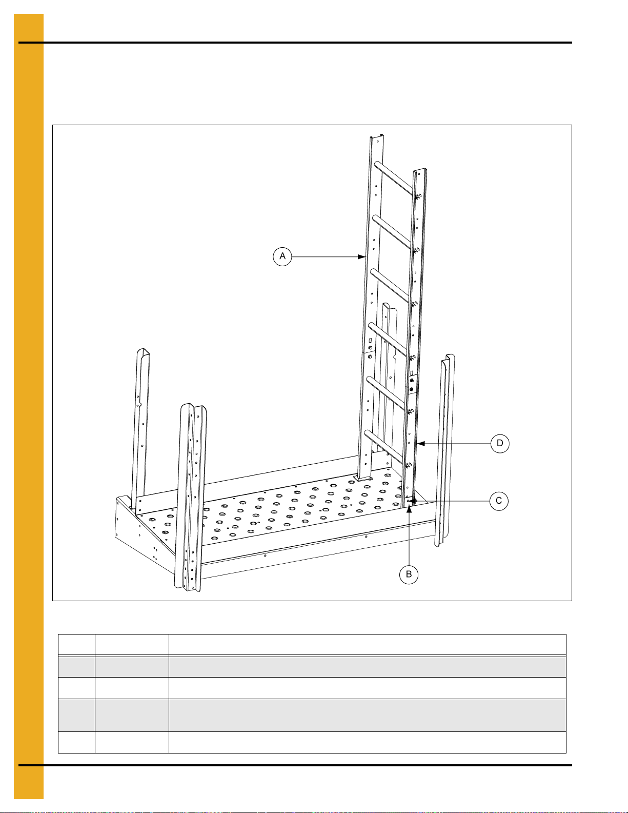
6. The last ladder section at each intermediate platform and at the bottom may need to be cut off for
proper fit. (See Figure 4AL.)
7. Anchor the last ladder section to the intermediate platform using the ladder base and 5/16" hardware.
You must drill the platform floor to attach the ladder base to the platform. (See Figure 4AL.)
Figure 4AL
Ref # Part # Description
A 4FOOTRF 4' Roll Formed Ladder
B LDR-5181 Intermediate Platform Ladder Base
C
D Cut the ladder to fit the intermediate platform.
62 PNEG-1773-EU 42'-135' “X” Series Ladder, Cage and Platform - European Standard
Attach ladder to ladder base using 5/16"-18 x 1" flange bolt (S-10260) and 5/16"-18
flange nut (S-10268).
Page 63

Ladder Intermediate
Platform Package
PNEG-1773-EU 42'-135' “X” Series Ladder, Cage and Platform - European Standard 63
Page 64

4. Assembly Instructions
“X” Series Ladder Intermediate Platform Package
Platform Package
1. Attach the wall angle to the sidewall sheet with 3/8" hardware. Assemble the left and right
intermediate platform brackets to the wall angles with 3/8" hardware. (See Figure 4AM.)
NOTE: Leave all hardware loose until completely assembled.
Assemble the platform to the front and back angles and platform brackets using the 5/16" truss bolts.
Using 5/16" hardware, assemble the posts.
Figure 4AM
Ref # Part # Description
A LDR-5168 Ladder Sidewall Angle
B LDR-5183 Intermediate Platform Back Post - Left
C LDR-5172 Ladder Intermediate Platform
D LDR-5184 Intermediate Platform Back Post - Right
E LDR-5179 Intermediate Platform Front Post (2)
F LDR-5180 Intermediate Platform Toe Board
G STX-0138 “X” Series Eave Platform Middle Angle (2)
H LDR-5175 Intermediate Platform Front Angle
I LDR-5173 Intermediate Platform Bracket - Right
J LDR-5174 Intermediate Platform Bracket - Left
K
L
M
Use 5/16"-18 x 3/4" truss bolt (S-10267) and 5/16"-18 flange nut (S-10268) to attach platform
floor and all substructure.
Attach all handrail posts to platform using 5/16"-18 x 1" flange bolt (S-10260) and 5/16"-18
flange nut (S-10268).
Attach ladder sidewall angle to intermediate platform bracket using 3/8-16" x 1" flange bolt
(S-7485) and 3/8"-16 flange nut (S-9426).
64 PNEG-1773-EU 42'-135' “X” Series Ladder, Cage and Platform - European Standard
Page 65

4. Assembly Instructions
NOTE: The parts pointed out on this page are listed on Page 66.
Platform Package (Continued)
2. Assemble the platform wall brace to the intermediate platform front posts and wall angles with
5/16" hardware. (See Figure 4AN.)
Attach the platform gate bracket to the gate before attaching it to the platform back post using
5/16" hardware.
Assemble the top and intermediate handrails to the post using 5/16" hardware.
PNEG-1773-EU 42'-135' “X” Series Ladder, Cage and Platform - European Standard 65
Figure 4AN
Page 66

4. Assembly Instructions
Platform Package (Continued)
Ref # Part # Description
A LDR-4088 Small Intermediate Handrail (2). Field cut to fit.
B LDR-4087 Large Intermediate Handrail (2). Field cut to fit.
C LDR-5185 Intermediate Platform Gate Bracket
D LDR-5182 Intermediate Platform Top Handrail (2)
E LDR-5168 Ladder Sidewall Angle
F LDR-5218 Ladder Safety Gate
G LDR-5206 Eave Platform Wall Brace
H
I
J
K
L
M LDR-5182 56.140" - Intermediate Platform Top Handrail
Attach intermediate platform door bracket to platform corner post using 5/16"-18 x 1"
flange bolt (S-10260) and 5/16"-18 flange nut (S-10268).
Attach intermediate handrail to handrail post using 5/16"-18 x 1" flange bolt (S-10260) and
5/16"-18 flange nut (S-10268).
Attach upper handrails to platform post using 5/16" x 2" bolt (S-7877) and 5/16"-18
flange nut (S-10268).
Attach safety gate assembly to intermediate platform door bracket using 5/16"-18 x 1"
flange bolt (S-10260) and 5/16"-18 flange nut (S-10268).
Attach eave platform wall brace to ladder sidewall angle using 5/16"-18 x 1" flange bolt
(S-10260) and 5/16"-18 flange nut (S-10268).
66 PNEG-1773-EU 42'-135' “X” Series Ladder, Cage and Platform - European Standard
Page 67

4. Assembly Instructions
Platform and Safety Cage Bar Package
3. Assemble the safety cage bars (knee brace) to the posts and front and back angles using
5/16" hardware. (See Figure 4AO.)
NOTE: Be sure the intermediate platform is level before tightening hardware.
Figure 4AO
Ref # Part # Description
A LDR-5171 24" Safety Cage Bar (4)
PNEG-1773-EU 42'-135' “X” Series Ladder, Cage and Platform - European Standard 67
Page 68

4. Assembly Instructions
Platform and Ladder Cage Package
4. Assemble the ladder and ladder brackets to the intermediate platform bracket using 5/16" hardware.
The top ladder rung must be level with the platform floor. (See Figure 4AP.)
Figure 4AP
Ref # Part # Description
A 4FOOTRF 4' Roll Formed Ladder
B LDR-5178 Intermediate Platform Ladder Bracket - Left
C LDR-5177 Intermediate Platform Ladder Bracket - Right
D
68 PNEG-1773-EU 42'-135' “X” Series Ladder, Cage and Platform - European Standard
Attach intermediate platform ladder bracket to platform wall bracket using 5/16"-18 x 1"
flange bolt (S-10260) and 5/16"-18 flange nut (S-10268).
Page 69

4. Assembly Instructions
Platform and Cage Package
5. Attach the ladder flare to the ladder using 5/16" hardware. You must drill the bottom hole through the
ladder and use 5/16" hardware. (See Figure 4AQ below and Figure 4AR on Page 70.)
Attach the cage hoops and cage splice brackets to the ladder flares and platform posts. This must
all be assembled at the same time using 5/16" hardware.
NOTE: Be sure the ladder flares are vertical and parallel to the platform posts by adjusting the
splice brackets. The ladder should be square to the platform.
Figure 4AQ
Ref # Part # Description
A LDR-5164 Safety Cage Hoop - Standard (4)
B LDR-5167 Safety Cage Hoop Splice (2)
C 4FOOTRF 4' Roll Formed Ladder
D LDR-5493 Formed Ladder Flare (2)
E
F
PNEG-1773-EU 42'-135' “X” Series Ladder, Cage and Platform - European Standard 69
Attach safety cage hoop to formed ladder flare using 5/16"-18 x 1" flange bolt (S-10260)
and 5/16"-18 flange nut (S-10268).
Attach safety cage hoop splice to handrail post using 5/16"-18 x 1" flange bolt (S-10260)
and 5/16"-18 flange nut (S-10268).
Page 70

4. Assembly Instructions
Platform and Cage Package (Continued)
Figure 4AR
NOTE: See Pages 54-60 for ladder and cage assembly.
70 PNEG-1773-EU 42'-135' “X” Series Ladder, Cage and Platform - European Standard
Page 71

Sidedraw Ladder
Platform Package
PNEG-1773-EU 42'-135' “X” Series Ladder, Cage and Platform - European Standard 71
Page 72

4. Assembly Instructions
“X” Series Sidedraw Ladder Platform Package
Platform Package
1. Attach the wall angle to the sidewall sheet with 3/8" hardware. Assemble the left and right
intermediate platform brackets to the wall angles with 3/8" hardware. (See Figure 4AS.)
NOTE: Leave all hardware loose until completely assembled.
Assemble the platform to the front and back angles and platform brackets using the 5/16" truss bolts.
Using 5/16" hardware, assemble ladder sidewall angle to intermediate platform bracket.
Figure 4AS
Ref # Part # Description
A LDR-5172 Ladder Intermediate Platform Floor Pan
B STX-0138 “X” Series Eave Platform Middle Angle (2)
C LDR-5180 Intermediate Platform Toe Board
D LDR-5175 Intermediate Platform Front Angle
E LDR-5174 Intermediate Platform Bracket - Left
F LDR-5168 Ladder Sidewall Angle (2)
G
H
72 PNEG-1773-EU 42'-135' “X” Series Ladder, Cage and Platform - European Standard
Use 3/8-16" x 1" flange bolt (S-7485) and 3/8"-16 flange nut (S-9426) to attach ladder
sidewall bracket to platform wall bracket left.
Use 5/16"-18 x 3/4" truss bolt (S-10267) and 5/16"-18 flange nut (S-10268) to attach platform
floor and all substructure.
Page 73

4. Assembly Instructions
Platform and Safety Cage Bar Package
2. Assemble platform post and 24" safety cage bar to platform with 5/16" hardware. Attach eave
platform wall brace to platform handrail post with 5/16" hardware. (See Figure 4AT.)
Figure 4AT
Ref # Part # Description
A LDR-5183 Intermediate Platform Back Post - Left
B LDR-5171 24" Safety Cage Bar (5)
C STX-0254 Sidedraw Platform Corner Post
D LDR-5179 Intermediate Platform Front Post (2)
E LDR-5206 Eave Platform Wall Brace
F
PNEG-1773-EU 42'-135' “X” Series Ladder, Cage and Platform - European Standard 73
Attach all handrail posts, eave platform wall brace, safety cage bars to platform
using 5/16"-18 x 1" flange bolt (S-10260) and 5/16"-18 flange nut (S-10268).
Page 74

4. Assembly Instructions
Platform and Handrail Package
3. Assemble top and intermediate handrails to the post using 5/16" hardware. (See Figure 4AU.)
Figure 4AU
Ref # Part # Description
A LDR-4087 Large Intermediate Handrail (3). Field cut to fit.
B LDR-5182 Intermediate Platform Top Handrail
C LDR-5302 Sidedraw Platform Handrail Short
D LDR-4088 Small Intermediate Handrail (3). Field cut to fit.
E
F
G LDR-5182 56.140" - Intermediate Platform Top Handrail
H LDR-5302 23-7/8" - Sidedraw Platform Handrail Short
Attach upper handrails to platform posts using 5/16" x 2" bolt (S-7877) and 5/16"-18
flange nut (S-10268).
Attach intermediate handrails to platform posts using 5/16"-18 x 1" flange bolt (S-10260)
and 5/16"-18 flange nut (S-10268).
74 PNEG-1773-EU 42'-135' “X” Series Ladder, Cage and Platform - European Standard
Page 75

4. Assembly Instructions
Platform and Swing Gate Package
4. Assemble the platform gate bracket to the gate before attaching it to the platform back post using
5/16" hardware. (See Figure 4AV.)
Figure 4AV
Ref # Part # Description
A LDR-5218 Ladder Safety Gate
B LDR-5185 Intermediate Platform Gate Bracket
C
PNEG-1773-EU 42'-135' “X” Series Ladder, Cage and Platform - European Standard 75
Attach intermediate platform door bracket and safety gate using 5/16"-18 x 1"
flange bolt (S-10260) and 5/16"-18 flange nut (S-10268).
Page 76

4. Assembly Instructions
Platform and Safety Cage Package
5. Attach the ladder flare to the ladder using 5/16" hardware. You must drill the bottom hole through the
ladder and use 5/16" hardware. (See Figure 4AW.)
Attach the cage hoops and cage splice brackets to the ladder flares and platform posts. This must
all be assembled at the same time using 5/16" hardware.
NOTE: Be sure the ladder flares are vertical and parallel to the platform posts by adjusting the
splice brackets. The ladder should be square to the platform.
Figure 4AW
Ref # Part # Description
A LDR-5164 Safety Cage Hoop Standard (4)
B LDR-5493 Formed Ladder Flare (2)
C LDR-5178 Intermediate Platform Ladder Bracket - Left
D LDR-5167 Safety Cage Hoop Splice (2)
E LDR-5177 Intermediate Platform Ladder Bracket - Right
F
G
H
Attach safety cage hoop splice to intermediate platform post and to safety hoop
standard using 5/16"-18 x 1" flange bolt (S-10260) and 5/16"-18 flange nut (S-10268).
Attach intermediate platform ladder bracket to platform wall bracket using 5/16"-18 x 1"
flange bolt (S-10260) and 5/16"-18 flange nut (S-10268).
Attach safety cage hoop standard to ladder flare using 5/16"-18 x 1" flange bolt (S-10260)
and 5/16"-18 flange nut (S-10268).
76 PNEG-1773-EU 42'-135' “X” Series Ladder, Cage and Platform - European Standard
Page 77

4. Assembly Instructions
Platform Ladder Bracket Package
6. Assemble the ladder to ladder brackets using 5/16" hardware. The top ladder rung must be level with
the platform floor. (See Figure 4AX below and Figure 4AY on Page 78.)
Figure 4AX
Ref # Part # Description
A 4FOOTRF 4' Roll Formed Ladder
B This hole must be drilled through ladder on right and left sides.
C
Attach intermediate platform ladder bracket to 4' roll formed ladder using
5/16"-18 x 1" flange bolt (S-10260) and 5/16"-18 flange nut (S-10268).
NOTE: See Pages 54-60 for ladder assembly instructions.
PNEG-1773-EU 42'-135' “X” Series Ladder, Cage and Platform - European Standard 77
Page 78

4. Assembly Instructions
Platform Ladder Bracket Package (Continued)
Figure 4AY
78 PNEG-1773-EU 42'-135' “X” Series Ladder, Cage and Platform - European Standard
Page 79

Platform Ladder Bracket Package (Continued)
4. Assembly Instructions
7. Platform placed at the bottom of the ring in which sidedraw placed. Figure 4AZ shows placement of
7 ring ladder package platform with sidedraw in 7
NOTE: Shown for placement purposes only. Ladder mounting parts not shown.
See Pages 54-60 for ladder assembly instructions.
th
ring. (See Figure 4AZ.)
Figure 4AZ
PNEG-1773-EU 42'-135' “X” Series Ladder, Cage and Platform - European Standard 79
Page 80

Platform Completed Assembly
Drawings and Parts List
80 PNEG-1773-EU 42'-135' “X” Series Ladder, Cage and Platform - European Standard
Page 81

1. 72'-135' Ladder Eave Platform Assembly - (See Pages 82-84.)
2. 42'-60' Ladder Eave Platform Assembly - (See Pages 85-87.)
3. “X” Series Ladder Intermediate Platform Package - (See Pages 88-90.)
4. “X” Series Sidedraw Ladder Platform Package - (See Pages 91-93.)
5. Parts List
PNEG-1773-EU 42'-135' “X” Series Ladder, Cage and Platform - European Standard 81
Page 82

5. Parts List
72'-135' Ladder Eave Platform Assembly
82 PNEG-1773-EU 42'-135' “X” Series Ladder, Cage and Platform - European Standard
Page 83

72'-135' Ladder Eave Platform Assembly Parts List
Ref # Part # Description Qty
1 STX-0080 Single Piece Platform Floor 1
2 STX-0014 Platform Toe Plate 1
3 STX-0081 “X” Series Platform Long Angle 2
4 STX-0011 Platform Short Angle 3
5 STX-0082 “X” Series Platform Bracket - Right 1
6 STX-0009 “X” Series Platform Bracket - Left 1
7 STX-0015 Platform Corner Post 3
8 STX-0076 Eave Platform Corner Post 1
9 LDR-5171 24" Safety Cage Bar 2
10 STX-0038 Platform Handrail Short 1
11 STX-0075 Eave Platform Top Rail - Long 1
5. Parts List
12 LDR-4087 Large Intermediate Handrail 2
13 LDR-4088 Small Intermediate Handrail 2
14 LDR-5185 Intermediate Platform Gate Bracket 1
15 LDR-5218 Ladder Safety Gate 1
16 LDR-5159 Eave Platform Ladder Bracket 2
17 LDR-5174 Intermediate Platform Bracket - Left 1
18 LDR-5168 Ladder Sidewall Angle 1
19 LDR-5177 Intermediate Platform Ladder Bracket - Right 1
20 LDR-5178 Intermediate Platform Ladder Bracket - Left 1
21 LDR-5493 Formed Ladder Flare 2
22 LDR-5207 Eave Platform Inside Post Bracket 1
23 LDR-5164 Safety Cage Hoop - Standard 4
24 LDR-5167 Safety Cage Hoop Splice 2
25 LDR-5204 Safety Cage Splice Bracket 1
26 LDR-5206 Eave Platform Wall Brace 2
N/S LDR-5173 Intermediate Platform Bracket - Right 1
N/S LDR-5205 Eave Platform Post Support 1
PNEG-1773-EU 42'-135' “X” Series Ladder, Cage and Platform - European Standard 83
Page 84

5. Parts List
72'-135' Ladder Eave Platform Assembly (Continued)
84 PNEG-1773-EU 42'-135' “X” Series Ladder, Cage and Platform - European Standard
Page 85

42'-60' Ladder Eave Platform Assembly
5. Parts List
PNEG-1773-EU 42'-135' “X” Series Ladder, Cage and Platform - European Standard 85
Page 86

5. Parts List
42'-60' Ladder Eave Platform Assembly (Continued)
86 PNEG-1773-EU 42'-135' “X” Series Ladder, Cage and Platform - European Standard
Page 87

42'-60' Ladder Eave Platform Assembly Parts List
Ref # Part # Description Qty
1 STX-0134 Single Piece Long Eave Platform Floor 1
2 STX-0136 “X” Series Eave Platform Long Angle 2
3 STX-0009 “X” Series Platform Bracket - Left 1
4 STX-0011 Platform Short Angle 2
5 STX-0137 “X” Series Long Eave Platform Short Angle 2
6 STX-0138 “X” Series Eave Platform Middle Angle 2
7 STX-0139 “X” Series Eave Platform Outside Corner Post 2
8 STX-0140 “X” Series Eave Platform Floor - Right 1
9 STX-0082 “X” Series Platform Bracket - Right 1
10 STX-0141 “X” Series Eave Platform Outside Center Post 1
11 LDR-4088 Small Intermediate Handrail 2
12 LDR-4087 Large Intermediate Handrail 2
5. Parts List
13 LDR-5171 24" Safety Cage Bar 4
14 STX-0142 “X” Series Eave Platform Toe Board 1
15 STX-0143 “X” Series Long Eave Platform Splice Angle 1
16 LDR-5159 Eave Platform Ladder Bracket 2
17 LDR-5174 Intermediate Platform Bracket - Left 1
18 LDR-5168 Ladder Sidewall Angle 1
19 LDR-5177 Intermediate Platform Ladder Bracket - Right 1
20 LDR-5178 Intermediate Platform Ladder Bracket - Left 1
21 LDR-5493 Formed Ladder Flare 2
22 STX-0148 “X” Series Eave Platform Inside Intermediate Rail 2
23 LDR-5164 Safety Cage Hoop - Standard 4
24 LDR-5167 Safety Cage Hoop Splice 2
25 STX-0144 “X” Series Eave Platform Inside Corner Post 2
26 LDR-5185 Intermediate Platform Gate Bracket 1
27 STX-0038 Platform Handrail Short 1
28 STX-0145 “X” Series Eave Platform Top Rail - Long 2
29 LDR-5218 Ladder Safety Gate 1
30 STX-0135 “X” Series Long Eave Platform Bracket 1
31 STX-0146 “X” Series Eave Platform Inside Center Post 2
32 STX-0147 “X” Series Eave Platform Inside Top Rail 2
PNEG-1773-EU 42'-135' “X” Series Ladder, Cage and Platform - European Standard 87
Page 88

5. Parts List
“X” Series Ladder Intermediate Platform Package
88 PNEG-1773-EU 42'-135' “X” Series Ladder, Cage and Platform - European Standard
Page 89

“X” Series Ladder Intermediate Platform Package Parts List
Ref # Part # Description Qty
1 LDR-5172 Ladder Intermediate Platform Floor Pan 1
2 LDR-5175 Intermediate Platform Front Angle 1
3 STX-0138 “X” Series Eave Platform Middle Angle 2
4 LDR-5173 Intermediate Platform Bracket - Right 1
5 LDR-5174 Intermediate Platform Bracket - Left 1
6 LDR-5179 Intermediate Platform Front Post 2
7 LDR-5183 Intermediate Platform Back Post - Left 1
8 LDR-5184 Intermediate Platform Back Post - Right 1
9 LDR-5167 Safety Cage Hoop Splice 2
10 LDR-5164 Safety Cage Hoop - Standard 4
11 LDR-5200 Intermediate Platform Wall Brace 2
5. Parts List
12 LDR-5180 Intermediate Platform Toe Board 1
13 LDR-5177 Intermediate Platform Ladder Bracket - Right 1
14 LDR-5178 Intermediate Platform Ladder Bracket - Left 1
15 LDR-5493 Formed Ladder Flare 2
16 LDR-5182 Intermediate Platform Top Handrail 2
17 LDR-4087 Large Intermediate Handrail 2
18 LDR-4088 Small Intermediate Handrail 2
19 LDR-5185 Intermediate Platform Gate Bracket 1
20 LDR-5218 Ladder Safety Gate 1
21 LDR-5171 24" Safety Cage Bar 4
22 LDR-5168 Ladder Sidewall Angle 2
23 LDR-5181 Intermediate Platform Ladder Base 2
PNEG-1773-EU 42'-135' “X” Series Ladder, Cage and Platform - European Standard 89
Page 90

5. Parts List
“X” Series Ladder Intermediate Platform Package (Continued)
90 PNEG-1773-EU 42'-135' “X” Series Ladder, Cage and Platform - European Standard
Page 91

“X” Series Sidedraw Ladder Platform Package
5. Parts List
PNEG-1773-EU 42'-135' “X” Series Ladder, Cage and Platform - European Standard 91
Page 92

5. Parts List
“X” Series Sidedraw Ladder Platform Package (Continued)
92 PNEG-1773-EU 42'-135' “X” Series Ladder, Cage and Platform - European Standard
Page 93

“X” Series Sidedraw Ladder Platform Package Parts List
Ref # Part # Description Qty
1 LDR-5172 Ladder Intermediate Platform Floor Pan 1
2 LDR-5175 Intermediate Platform Front Angle 1
3 LDR-5176 Intermediate Platform Back Angle 2
4 LDR-5173 Intermediate Platform Bracket - Right 1
5 LDR-5174 Intermediate Platform Bracket - Left 1
6 LDR-5179 Intermediate Platform Front Post 2
7 LDR-5183 Intermediate Platform Back Post - Left 1
8 STX-0254 Platform Corner Post 1
9 LDR-5167 Safety Cage Hoop Splice 2
10 LDR-5164 Safety Cage Hoop - Standard 4
11 LDR-5302 Sidedraw Platform Handrail Short 1
5. Parts List
12 LDR-5180 Intermediate Platform Toe Board 1
13 LDR-5177 Intermediate Platform Ladder Bracket - Right 1
14 LDR-5178 Intermediate Platform Ladder Bracket - Left 1
15 LDR-5493 Formed Ladder Flare 2
16 LDR-5182 Intermediate Platform Top Handrail 2
17 LDR-4087 Large Intermediate Handrail 3
18 LDR-4088 Small Intermediate Handrail 3
19 LDR-5218 Ladder Safety Gate 1
20 LDR-5185 Intermediate Platform Gate Bracket 1
21 LDR-5171 24" Safety Cage Bar 5
22 LDR-5168 Ladder Sidewall Angle 2
23 LDR-5200 Intermediate Platform Wall Brace 2
PNEG-1773-EU 42'-135' “X” Series Ladder, Cage and Platform - European Standard 93
Page 94

NOTES
94 PNEG-1773-EU 42'-135' “X” Series Ladder, Cage and Platform - European Standard
Page 95

6. Warranty
9101239_1_CR_rev8.DOC (revised January 2014)
GSI Group, LLC Limited Warranty
The GSI Group, LLC (“GSI”) warrants products which it manufactures to be free of defects in materials and workmanship
under normal usage and conditions for a period of 12 months after sale to the original end-user or if a foreign sale,
14 months from arrival at port of discharge, whichever is earlier. The end-user’s sole remedy (and GSI’s only obligation)
is to repair or replace, at GSI’s option and expense, products that in GSI’s judgment, contain a material defect in materials
or workmanship. Expenses incurred by or on behalf of the end-user without prior written authorization from the GSI
Warranty Group shall be the sole responsibility of the end-user.
Warranty Extensions:
The Limited Warranty period is extended for the following products:
Product Warranty Period
Performer Series Direct Drive Fan Motor 3 Years * Warranty prorated from list price:
AP Fans and Flooring
AP and Cumberland Flex-Flo/Pan Feeding System Motors 2 Years
Cumberland
Feeding/Watering
Systems
Grain Systems
Grain Systems
Farm Fans
Zimmerman
All Fiberglass Housings Lifetime
All Fiberglass Propellers Lifetime
Feeder System Pan Assemblies 5 Years **
Feed Tubes (1-3/4" and 2.00") 10 Years *
Centerless Augers 10 Years *
Watering Nipples 10 Years *
Grain Bin Structural Design 5 Years
Portable and Tower Dryers 2 Years
Portable and Tower Dryer Frames and
Internal Infrastructure †
5 Years
0 to 3 years - no cost to end-user
3 to 5 years - end-user pays 25%
5 to 7 years - end-user pays 50%
7 to 10 years - end-user pays 75%
** Warranty prorated from list price:
0 to 3 years - no cost to end-user
3 to 5 years - end-user pays 50%
† Motors, burner components
and moving parts not included.
Portable dryer screens included.
Tower dryer screens not included.
GSI further warrants that the portable and tower dryer frame and basket, excluding all auger and auger drive components,
shall be free from defects in materials for a period of time beginning on the twelfth (12
and continuing until the sixtieth (60
th
) month from the date of purchase (extended warranty period). During the extended
th
) month from the date of purchase
warranty period, GSI will replace the frame or basket components that prove to be defective under normal conditions
of use without charge, excluding the labor, transportation, and/or shipping costs incurred in the performance of this
extended warranty.
Conditions and Limitations:
THERE ARE NO WARRANTIES THAT EXTEND BEYOND THE LIMITED WARRANTY DESCRIPTION SET FORTH
ABOVE. SPECIFICALLY, GSI MAKES NO FURTHER WARRANTY OF ANY KIND, EXPRESS OR IMPLIED,
INCLUDING, WITHOUT LIMITATION, WARRANTIES OF MERCHANTABILITY OR FITNESS FOR A PARTICULAR
PURPOSE OR USE IN CONNECTION WITH: (I) PRODUCT MANUFACTURED OR SOLD BY GSI OR (II) ANY ADVICE,
INSTRUCTION, RECOMMENDATION OR SUGGESTION PROVIDED BY AN AGENT, REPRESENTATIVE OR
EMPLOYEE OF GSI REGARDING OR RELATED TO THE CONFIGURATION, INSTALLATION, LAYOUT, SUITABILITY
FOR A PARTICULAR PURPOSE, OR DESIGN OF SUCH PRODUCTS.
GSI shall not be liable for any direct, indirect, incidental or consequential damages, including, without limitation, loss of
anticipated profits or benefits. The sole and exclusive remedy is set forth in the Limited Warranty, which shall not exceed
the amount paid for the product purchased. This warranty is not transferable and applies only to the original end-user. GSI
shall have no obligation or responsibility for any representations or warranties made by or on behalf of any dealer, agent
or distributor.
GSI assumes no responsibility for claims resulting from construction defects or unauthorized modifications to products
which it manufactured. Modifications to products not specifically delineated in the manual accompanying the equipment at
initial sale will void the Limited Warranty.
This Limited Warranty shall not extend to products or parts which have been damaged by negligent use, misuse, alteration,
accident or which have been improperly/inadequately maintained. This Limited Warranty extends solely to products
manufactured by GSI.
Prior to installation, the end-user has the responsibility to comply with federal, state and local codes which apply to the
location and installation of products manufactured or sold by GSI.
PNEG-1773-EU 42'-135' “X” Series Ladder, Cage and Platform - European Standard 95
Page 96

This equipment shall be installed in accordance with
the current installation codes and applicable
regulations, which should be carefully followed in all
cases. Authorities having jurisdiction should be
consulted before installations are made.
1004 E. Illinois St.
Assumption, IL 62510-0020
Phone: 1-217-226-4421
Fax: 1-217-226-4420
www.gsiag.com
GSI is a worldwide brand of AGCO Corporation.
Copyright © 2017 by The GSI Group, LLC
Printed in the USA
CN-332667
 Loading...