

Page 1
™
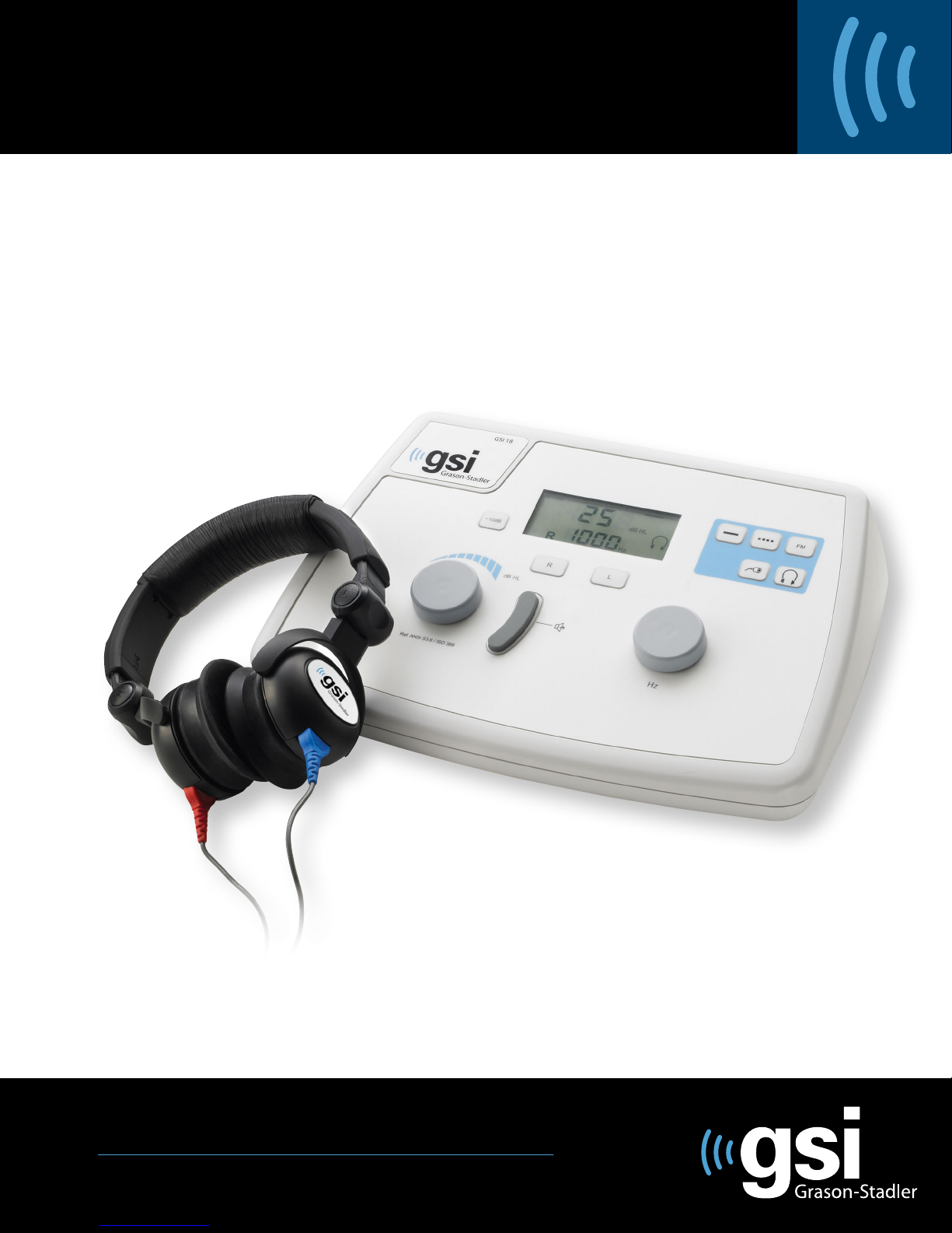
GSI 18
USER MANUAL
Setting The Clinical Standard www.grason-stadler.com
Grason-Stadler, 7625 Golden Triangle Drive, Suite F, Eden Prairie MN 55344
800-700-2282 • 952-278-4402 • fax 952-278-4401 • e-mail info@grason-stadler.com
Part Number 1718-0100 Rev E
Page 2
GSI 18
Title:
GSI 18 User Manual
.
Copyright © 2 011 Grason-Stadler Inc
may be reproduced or transmitted in any form or by any means without the prior written
permission of Grason-Stadler Inc
Grason-Stadler.
Compliance
The CE0344 mark identifies compliance with the Medical Device Directive 93/42/EEC.
Grason-Stadler is an ISO 13485-certifed corporation.
European Authority Repr esentative
Grason-Stadler
Kongebakken 9
2765 Smørum
Denmark
.
All rights reserved. No part of this publication
The information in this publication is proprietary to
0344
1718-0100 Rev. E i
Page 3
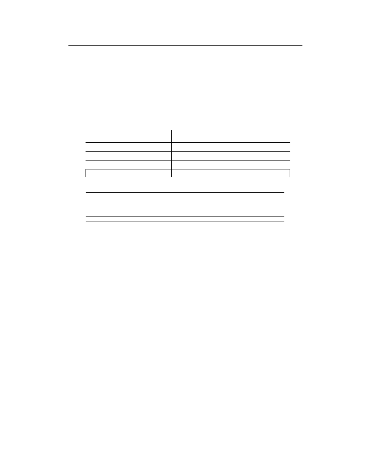
Supplied Accessories
WARNING
GSI 18
!
Check that all accessories itemized in Accessories supplied below are received in good
condition. If any accessories are missing, contact GSI immediately. See the Specifications
section for the catalog numbers of accessories and also for a listing of optional accessories.
Part Numbers
Test headset (DD45) (with Headband) 8000-0181
Audiogram Forms (1 pad of 50) 1718-9600
Instruction Manual 1718-0100
Bag, Carrying 143-414700
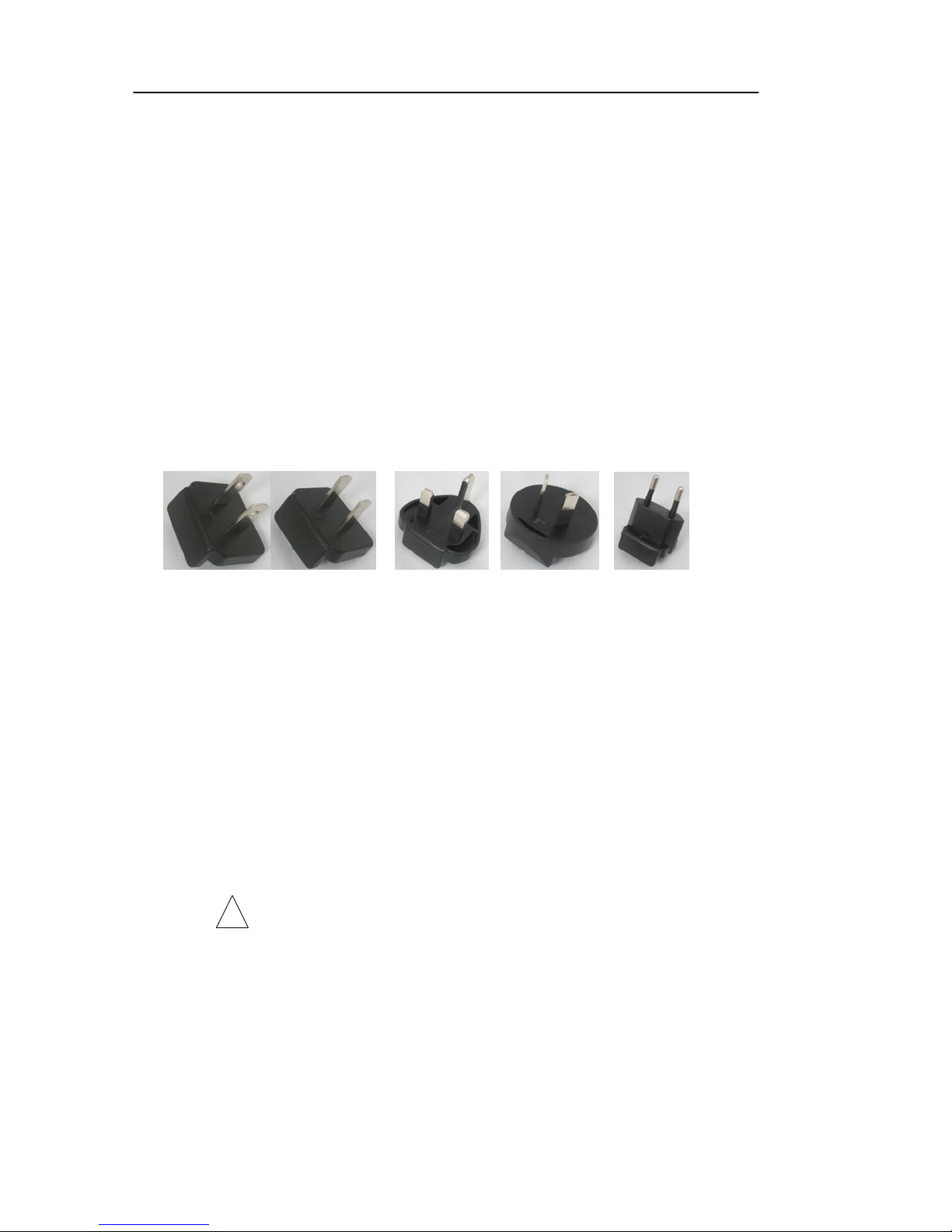
AC Power Module (1718-9700 or 1718-9701 only) UE100503HKKK3-P
Europe, Italy, India,
North America/Japan UK-Ireland Australia, China Israel, S. Africa, Korea,
5 each, AA Alkaline Batteries (1718-9705 or 1718-9706 only)
Quick Reference Guide - Threshold Audiometry 1718-0140
Russia
Optional Accessories
Response Handswitch 7874-0156
Patch Cord, 2 Conductor 4204-0505
Audiocups 8000-0155
Insert Phone Assembly 3A (10 ohm impedance) 1700-9710
Insert Phone Assem
Use only Grason-Stadler su pplied compo nen ts and acc essories.
bly 5A (50 ohm impedance) 1700-0882
ii 1718-0100 Rev. E
Page 4
Safety Summary
WARNING
the patient and/or user.
!
Safety Notes
WARNING
!
!
iii
GSI 18
In this manual the following two labels identify potentially dangero us or
destructive conditions and procedures:
The
label identifies conditions or practices that may present danger to
CAUTION
The CAUTION label identifies conditions or practices that could result in damage to
the equipment.
NOTE: Notes help you identify areas of possible confusion and avoid potential
problems during system operation.
WARNING
The GSI 18 is designed for compliance to IEC and UL 60601-1 when used in the
patient vicinity. The GSI 18 is equipped with a specific power transformer (pn:
UE100503HKKK3-P), which should not be interchanged with any other
transformer or supply.
Any program aimed at obtaining reliable records of hearing thresholds should be
staffed and supervised by appropriately-trained individuals.
Latex is not used anywhere in the manufacturing process.
The base material for the earphone cushions is made from natural and synthetic
rubber.
1718-0100 Rev. E
Page 5

WARNING
!
GSI 18
This symbol indicates the location of a service adjustment part and is
intended for service personnel only. The GSI 18 is a specifically calibrated
audiometer and the periodic service and adjustments for the instrument that
may be required should be done only by an authorized GSI service technician.
Please read the entire manual prior to using the GSI 18 to become fa miliar with
the test functions and proper accessory connections.
Accessory equipment connected to the analog and digital interfaces must be
certified to the respective IEC standards (IEC950 for data processing or IEC
60601-1 for medical equipment). Furthermore, all configurations shall comply
with the system standard IEC 60601-1-1. Anyone who connects additional
equipment to the signal i n put or si gnal output port configures a medical system,
and is therefore responsible that the system complies with the requirements of
the system standard IEC60601-1-1. If in doubt, consult the technical service
department or local GSI representative.
iv 1718-0100 Rev. E
Page 6

GSI 18
Customer Responsibility
WARNING
!
This product and its components will perform reliably only when operated and
maintained in accordance with the instructions contained in this manual,
accompanying labels, and/or inserts. A defective product should not be used.
Parts which may be broken or missing or are visibly worn, distorted or
contaminated should be replaced immediately with clean, genuine replacement
parts manufactured by or available from GSI.
The responsibility of GSI for a malfunction product is limited by the warranty set
forth in this manual. Should repair or replacement of this product become
necessary after the warranty period, the customer should seek advice from GSI
Technical Support prior to such repair or replacement. If this product is in need of
repair, it should not be used until all repairs have been made and the unit is
functioning properly and ready for use. The owner of this product has sole
responsibility for any malfunction resulting from improper use or maintenance, or
repair by anyone other than GSI, and from any malfunction caused by parts that
are damaged or modified by anyone other than GSI.
This product should not be used in the presence of fluid that can come into
contact with any of the electronic components or wiring. Should the user suspect
fluids have contacted the system components or accessories, the unit should not
be used until deemed safe by a GSI certified service technician.
Do NOT use in the presence of flammable gaseous mixtures. Users should
consider the possibility of explosions or fire when using this device in close
proximity to flammable anesthetic gases.
Periodically, have a service technician perform electrical safety checks on the u nit
in order to maintain continued compliance to IEC and UL 60601-1.
v 1718-0100 Rev. E
Page 7

GSI 18
Warranty
We, Grason-Stadler, warrant that this product is free from defects in material and workmanship,
and when properly installed and used, will perform in accordance with applicable specifications.
Within one year after original shipment, if it is found not to meet this standard, it will be
repaired, or at our option replaced, at no charge except for transportation costs when returned to
an authorized GSI product service facility. If field service is requested, there will be no charge
for labor or material; however, there will be a charge for travel expense at the service center’s
current rate.
NOTE: Changes in the product not approved in writing by Grason-Stadler shall void this
warranty. Grason-Stadler shall not be liable for any indirect, special or consequential damages,
even if notice has been given in advance of the possibility of such damages.
THIS WARRANTY IS IN LIEU OF ALL OTHER WARRANTIES, EXPRESSED OR
IMPLIED, INCLUDING BUT NOT LIMITED TO, ANY IMPLIED WARRANTY OF
MERCHANTABILITY OF FITNESS FOR A PARTICULAR PURPOSE.
1718-0100 Rev. E vi
Page 8

GSI 18
Specifications
The GSI 18 meets the following standards:
ANSI S3.6 (2004) Specification for Audiometers (Type 4)
IEC 60645-1 (2002) Electroacoustics - Audiological Equipment -
Pure Tone Audiometers (Type 4)
It is Class 1, internally powered with Type B
applied parts.
IEC 60601-1 (2003) Medical Electrical Equipment Part 1 - General
Requirements for Safety
UL 60601 Medical Electrical Equipment, Part 1 -General
Requirements for Safety
CAN/CSA-C22.2 No. 601.1-M90 (2003) Medical Electrical Equipment - Part 1: General
Requirements for Safety
IEC/EN 60601-1-2 (2001) Medical Electrical Equipment Part 1 -
Electromagnetic compatibility requirements
vii
1718-0100 Rev. E
Page 9
Frequency Range
GSI 18
Discrete Frequencies: 125, 250, 500, 750, 1000, 1500, 2000, 3000, 4000,
6000, 8000 Hz
Accuracy: ±2%
Total Harmonic Distortion: <2.5% measured acoustically at the maximum Hz for
frequencies below 5000 Hz and measured electrically
above 5000 Hz.
Intensity
Ranges In increments of 5 dB steps
125 Hz -10 to 50 dB HL
500 to 4000 Hz -10 to 90 dB HL
6000 Hz -10 to 85 dB HL
250 and 8000 Hz -10 to 70 dB HL
The above intensity ranges apply to the DD45 earphones.
NOTE: The maximum output values in dB HL are reduced by 10 dB when insert
phones (EAR 3A/5A) are used, except for 6 kHz where the maximum dB HL is
reduced by 20 dB.
NOTE: A “+10” dB button extends the maximum at all frequencies by 10 dB.
Accuracy: 125 to 4000 Hz, ±3 dB
6000 to 8000 Hz, ±5 dB
Signal to Noise Ratio: >70 dB
Tone Type
Rise/Fall Time: 20-50 msec
Continuous: Steady when present bar depressed
Pulsed: 2.5
FM: ±5%, 5 Hz, Triangular modulation
pulse/sec
Head set
DD45 Earphones with Type 51 Cushions (10 ohm impedance).
Headband: Exerts a force between 4 and 5 N when the
earphones are separated by 145mm.
1718-0100 Rev. E
viii
Page 10
Power
GSI 18
Line Voltage: The AC-DC adapter is a universal auto-ranging with
an input voltage range of 100 - 240VAC at 50 - 60 Hz.
Consumption: 1.5 Watts
Battery
Types: 5 each Alkaline AA 1.5V
5 each Rechargeable Nicad or NiMH AA 1.2V
NOTE: The instrument does not provide a recharging circuit for these batteries.
Capacity: Minimum of 10 hours of power for either battery type.
A Low Battery icon will display when there is
approximately 1 hour left of power.
Environmental
Temperature
Operating: 59° F to 104° F (15° C to 40° C)
NOTE: Warm-up time is required if storage temperature is different from room temperature.
Ambient Pressure: 98 kPa to 104 kPa
Warm-up Time: 10 minutes for instruments stored at room temperature
Storage/Shipping: -30° F to 149° F (-34° C to 65° C)
Battery Storage: -4° F to 105° F (-20° C to 40° C)
Humidity: 15% to 95%
Mechanical
Dimensions: 12.59” W x 8.76” D x 3.18” H
(32 cm W x 22.3 cm D
Weight: 2.55 lbs (1.16 Kg) with 5 AA batteries
x 8.1 cm H)
ix
1718-0100 Rev. E
Page 11
1718-0100 Rev. E
x
Electromagnetic Compatibility
GSI 18
Page 12

Preface
Table of Contents
Chapter 1
Introduction
Chapter 2
Operation
Title…………………………………..………..……..………....…..i
Supplied accessories…….…………….……...……........................ii
Safety summary...............................................................................iii
Safety notes…………….……………..………..……….…............iii
Customer responsibility…….…….…....……...................................v
Warranty ..........................................................................................vi
Specifications .................................................................................vii
Electromagnetic compatibility………..…….....………...................x
Unpacking and inspection..............................................................1-1
Recycling / disposal.......................................................................1-2
Installation ....................................................................................1-3
Rear panel connectors....................................................................1-3
Bottom panel .................................................................................1-3
Bottom panel .................................................................................1-5
Controls and indicators..................................................................1-6
LCD display...................................................................................1-8
AC power.....................................................................................1-10
Connecting the AC power………….….………...…..…….........1-10
Disconnecting the AC power……….…….……....……........….1-10
Battery operation ..........................................................
Sleep mode ..................................................................................1-11
Low battery indicator ..................................................................1-11
Replacing the batteries ................................................................1-12
Removing batteries………………….…….…...……..….......…1-13
Placing new batteries……………….…….…...…………....…..1-14
Preliminary check..........................................................................2-1
Pretest noise recovery period.........................................................2-2
Test environment ...........................................................................2-3
Providing patient instructions........................................................2-4
Placing the earphones....................................................................2-4
Response handswitch………..….……………...….………….....2-5
GSI Audiogram form………………....…………….….……...…2-5
Routine test administration............................................................2-6
Transducer selection……………….………….....….…......…….2-6
HL knob………..…………………..……………........…...……..2-6
Range Extension pushbutton………..………….…..........……....2-7
Tone Type selector…………………..……………..........…….....2-7
Typical testing session ..................................................................2-8
Pretest review………………………..….……...….…….....……2-8
Familiarization……………………..………...……..….....……...2-8
Determining the threshold (Pure Tone)….……….....….…....…..2-9
Testing procedure……………………….…..…….…….…....…..2-9
...............1-11
1718-0100 Rev. E
Page 13

Chapter 3
GSI 18
Routine
Maintenance
Appendix A
GSI Country Kit
Appendix B
Reference
Threshold Values
Bibliography
Index
ii
Preventive maintenance...............................................................3-1
Cleaning the GSI 18 …………………….….…........….…...…..3-1
Cleaning and disinfecting agents …..….….....…..…..…..…......3-2
Cleaning patient contact reusable devices….…...…....…...........3-2
Routine calibration check .......................................................... 3-3
Earphone cords .......................................................................... 3-4
Hum and random noise............................................................... 3-4
Distortion and frequency shift ................................................... 3-4
Special messages ....................................................................... 3-5
l...........
Ca
Exx............................................................................................. 3-5
................................................................................... 3-5
1718-0100 Rev. E
Page 14

Chapter 1
Introduction
The GSI 18 Audiometer is a single-channel, pure tone, air conduction, portable
instrument designed to provide basic audiometric screening capability for physicians’
offices, schools and industry. The lightweight design allows easy transport to a variety
of testing locations. The clearly labeled front panel controls and full frequency range
make accurate, reliable testing a simple matter for any user.
The GSI 18 is a precisely designed and calibrated instrument. With proper care, it will
deliver accurate sound-pressure levels to subjects’ ears for hearing screening programs.
NOTE: The GSI 18 should be calibrated yearly (or sooner if a problem develops) by a
GSI certified technician. See Chapter 3.
Unpacking and inspection
Although this GSI 18 was carefully tested, inspected and packed for shipping, it is good
practice after receiving the instrument to immediately examine the exterior of the
container for any signs of damage. Notify the carrier if any damage is noted.
Carefully remove the GSI 18 from its shipping container. If the instrument appears to
have suffered mechanical damage, notify the carrier immediately so that a proper claim
can be made. Be certain to save all packing materials so that the claim adjuster can
inspect it as well. As soon as the carrier has completed the inspection, notify a GSI
representative.
If the instrument must be returned to the factory, repack it carefully (in the original
contai
ner if possible) and return it prepaid to the factory for necessary adjustments.
1718-0100 Rev. E
1-1
Page 15
GSI 18
Recycling / disposal
CAUTION
Grason-Stadler A/S
!
Many local laws and regulations require special procedures to recycle or
dispose of electric equipment-related waste including batteries, printed
circuit boards, electronic components, wiring and other elements of
electronic devices. Follow all of your respective local laws and regulations for
the proper disposal of batteries and any other parts of this system.D-9
Check the Grason-Stadler website for recommended instructions and addresses for proper
return or disposal of electronic wastes relating to Grason-Stadler products in Europe and
other localities.
The contact information for the WEEE - In Europe:
Kongebakken 9
2765 Smørum
Denmark
CRV no. 21113379
1-2 1718-0100 Rev. E
Page 16

Introduction
No.
Symbol
Description
Introduction
Installation
1. Plug the power cord into the appropriate jack (R5) on the rear panel.
2. Plug the power cord from the Power Module into a line power (mains) outlet.
3. Plug the earphones into the earphone jacks on the rear panel. R3 is for the right and R4 is
for the left earphone/insert phone.
4. Turn the power switch to ON (R6).
Rear panel connectors
R1 R2 R3 R4 R5 R6
Figure 1: Rear panel connectors.
R1 -Covered by a sticker and intended for service personnel only.
R2 -Patient Hand Switch input jack (standard phone jack).
R3 -Right ear phone output jacks (standard phone plug). Insert either DD45
Headphone or Insert Earphone jacks.
R4 - Left earphone output jacks (standard phone jack). Insert either DD45
Headphones or Insert Earphone plugs.
R5 -Power Input jack (2.1 mm pin).
R6 - Power switch.
Table of symbols on the GSI 18
1
2
3
0344
4
3145885
5
1-3 1718-0100 Rev. E
Attention, consult accompanying documents.
Date of manufacture.
CE Marked in accordance with the European
Council Directive 93/42/EEC concerning medical
devices.
Medical device listing mark for U.S. and Canada
by Intertek Testing Service.
Special Recycling Required. Do not dispose in
landfill.
Page 17

GSI 18
1-4
No. Symbol Description
6
7
8
9
10
11
12
13
14
15
16
17
18
19
Type B equipment.
Reference Symbol.
Stand-by.
Right Ear.
Left Ear.
Patient Response Button.
AC Power.
Manufacturer.
European Representative.
Keep Dry.
Lot Number.
Serial Number.
Transport and storage temperature range.
This Side Up.
1718-0100 Rev. E
Page 18

Introduction
WARNING
!
Do not turn on/off system power while a patient is wearing the headsets or insert
earphones.
Use only the GSI provided power supply. The GSI 18 provided power supply
should only be connected to a power source meeting the following range: 100240VAC, 50-60Hz. In North America, the power source should be a maximum of
120VAC.
Bottom panel
B1 B2
Figure 2
B1 - Label location includes serial number of system.
B2 -Battery compartment
See Replacing the Batteries for detailed instructions.
1718-0100 Rev. E 1-5
Page 19

GSI 18
Controls and indicators
F1 F2 F3 F4 F5
+10dB
FM
R
dB HL
Ref / ANS I S3.6 / ISO 389
L
Hz
F12 F11 F10 F9 F8 F7 F6
Figure 3: Front panel controls and indicators.
F1
-Range extension pushbutton allows you to increase the stimulus intensity 10 dB
above the standard maximum HL at any frequency
.
When in use, a “+” appears
on the LCD.
F2
-Liquid Crystal Display (LCD).
F3
-Selects steady stimulus tone type. The symbol is shown in the upper right hand
corner of the display when selected.
F4
-Selects pulsed stimulus tone type. The symbol is shown in the upper right hand
corner of the display when selected.
F5
-Selects frequency modulated stimulus tone type
. FM is shown in the upper right
hand corner of the display when selected.
1-6 1718-0100 Rev. E
Page 20

F6
– Selects the DD45 calibration file for transducers. When the
pressed, the display will flash
.
Press the button again to engage the
Introduction
button is
TDH 39
Transducer.
F7
- Selects insert earphone calibration file for transducers. When the
is pressed, the display will flash
transducers
F8
- Control for setting the stimulus frequency. Frequency is indicated in the bottom
center of the display.
- Select to present the stimulus to the Left ear. An “L” will appear in the lower
F9
right side of the display to indicate the stimulus is being routed to the left ear.
F10
-Present bar for stimulus presentation. The symbol appears on the left side of
the display when the stimulus is being presented.
F11
-Select to present the stimulus to the Right ear. An “R” will appear in the lower
left side of the displa
F12
-Hearing Level knob for setting the stimulus intensity level. Level is indicated on
the center top of the display.
NOTE:
Type B applied part.
The above symbol is located on the rear panel of the GSI 18 and denotes a
The symbol is shown on the right side of the display when selected.
. P
.
The symbol
ress the
y to indicate the stimulus is being routed to the right ear.
is shown on the right side of the display when selected.
button again to engage the insert
button
1718-0100 Rev. E 1-7
Page 21

GSI 18
LCD display
5 6
7 8
Legend
1-8
1
15 14 13 12
2
11
3
4
Figure 4 - LCD Display
Icons/LEDs Description
1
2
3
4
5
6
Indicates power is on.
Indicates the current software version.
When displayed, the stimulus is being presented.
When displayed, an additional 10dB is available at the test
frequency.
When displayed, indicates the Patient Response button is being
pressed.
Stimulus is being presented to the right ear.
10
9
7
8
9
10
11
12
13
Stimulus frequency indicator.
Stimulus is being presented to the left ear.
Indicates the battery is low.
The headphone calibration file is applied to the stimulus and
Headphones should be used. Press this button twice to activate
the calibration file.
The insert phone calibration file is applied to the stimulus and
Insert phones should be used as the transducer
this button twice to activate the calibration file.
The stimulus is a Frequency Modulated (FM) tone.
The stimulus is a continuous tone.
.
Press
1718-0100 Rev. E
Page 22

Legend Icons/LEDs
14
15
Introduction
Description
The stimulus is a pulsed tone.
Stimulus presentation level.
or
Not enough power from the batteries to operate the system.
1718-0100 Rev. E
1-9
Page 23

GSI 18
AC power
An AC power supply can be purchased to use with the GSI 18.
!
WARNING
Use only the GSI provided power supply. The GSI 18 provided power supply
should only be connected to a power source meeting the following range:
100-240VAC 50-60Hz. In North America, the power source should be a
maximum 120VAC.
Connecting the AC power
1. Ensure the system is turned off while connecting the AC Power.
2. Plug the AC power supply into the power supply receptacle located next to the
power switch on the rear panel.
3. Connect the power cord to the Power Supply brick.
4. Plug the Power cord into the wall socket.
5. Turn the power ON.
When the power supply is plugged into the unit, the power from the batteries will be
switched off automatically to preserve battery life.
Disconnecting the AC power
1. Turn the system OFF.
2. Disconnect the power supply from the wall outlet.
3. Remove the
power supply from the rear panel.
1-10 1718-0100 Rev. E
Page 24

Introduction
Battery operation
charger for
to ensure a
of batteries will be available. The system was designed to operate for
WARNING
!
GSI 18 r equires 5 x 1.5V AA alkaline batteries. It can also use 5 x 1.2V AA NiMH or
NiCad batteries if rechargeable batteries are desired. The GSI 18 does not have a built-in
charger, rechargeable batteries should be purchased with the recommended
those batteries. GSI recommends the purchase of extra rechargeable batteries
fully charged supply
10 hours on rechargeable batteries. Alkaline batteries may last longer than 10 hours.
Remove the batteries from the GSI 18 if it is not going to be used for an extended time.
Sleep mode
When using battery power, the GSI 18 will enter a power saving mode (this is called sleep
mode and is indicated by dashes on the LCD display) if the buttons on the Front Panel
have not been pressed for 5 minutes. To exit the sleep mode, press the Presentation
button.
Low battery indicator
When there is approximately 1 hour of battery time left, the icon will be displayed on the
screen.
When the battery can no longer provide enough power to operate the GSI 18, the word
OFF will be displayed on the LCD and the system will no longer function. At that point,
replace the batteries (with new or fully charged batteries) or use the AC Power Module to
continue testing.
1718-0100 Rev. E 1-11
Page 25

GSI 18
Replacing the batteries
WARNING
!
Do not touch the patient and the battery terminals at the same time. The battery
cover is to be closed at all times except when replacing the batteries.
Batteries are to be replaced only by qualified personnel. Always turn off the
system before replacing the batteries.
Always inspect batteries for leakage and do not use if the batteries show any
signs of damage. The batteries should be the same type. When replacing
batteries, replace all of the batteries at the same time for optimal battery life.
The GSI 18 requires 5 x 1.5V AA alkaline batteries. It can also use 5 x 1.2V AA
NiMH or NiCad batteries if rechargeable batteries are desired.
1-12 1718-0100 Rev. E
Page 26

Introduction
Removing batteries
The battery compartment on the GSI 18 is located on the bottom of the base unit.
To open the battery compartment,
1.
Gently squeeze the tab toward the door and away from the concave half circle
and lift the door upward.
Figure 5 - Opening the battery compartment.
2.
Reach into the compartment through the empty battery slot and gently force the
battery up until it is free from the silver battery contacts.
.
Repeat for all 5 batteries. Do not simultaneously touch both sides of the battery
3
contacts at any time.
1718-0100 Rev. E 1-13
Page 27

GSI 18
Placing new batteries
Before placing new batteries in the battery compartment, always inspect batteries for
leakage and do not use batteries that show any signs of damage.
1.
Place the batteries starting with the battery slot farthest from the slot that is not
.
Be sure to match the + side of the battery with the marked + side for each
used
battery slot.
Figure 6 - Placing new batteries.
2.
Place the + side of the battery in at an angle and then push down on the – side of
the battery until the battery fits securely.
3.
Replace the battery compartment cover by inserting the square pegs into the slots
and gently pushing down until the tab snaps into place and the compartment door
is flush with the bottom of the GSI 18.
1-14 1718-0100 Rev. E
Page 28

1.
Prior to testing, ensure that the power cord or the batteries are in place and
purposes.
after each
alcohol or mild
into the earphone
earphone cords between
1718-0100 Rev. E 2-1
Chapter 2
Operation
Preliminary check
Throughout this chapter are references to front panel (F) and rear panel (R) connectors,
controls and indicators. Please refer to Figure 1 - Rear Panel connectors, Figure 3 Front panel controls and indicators and Figure 4 - LCD Display in Chapter 1 of this
manual for specific descriptions and locations.
earphone cords are plugged in securely.
Turn the audiometer on.
2.
3.
Select the desired tone type (steady, pulsed or FM).
4.
Make whatever notations the procedure requires on the audiogram form.
!
CAUTION
Always handle earphones with care. Neither drop them nor permit them to
be squeezed together. Severe mechanical shock may change their
operating characteristics and require their replacement.
IMPORTANT: Always clean and maintain earphone cushions for hygiene
Check periodically for cracking or signs of wear. Cleanse cushions daily or
use (depending upon population being tested). Use a solution of diluted
soap and water, taking care not to get any of the cleaning solution
speaker. Use earphones only when completely dry. Insert the
the earphone cushions during storage to prevent damage from mechanical shock.
Page 29

GSI 18
WARNING
!
trained individuals. Training
audiometric technicians in
Pretest noise recovery period
NOTE: The GSI 18 is a versatile audiometer designed for use in physician offices,
schools, industrial settings, the military, etc. The generic term “subject” used in this
manual is used to identify the person whose hearing is being evaluated.
Two prerequisites are of particular importance to the procurement of reliable
audiograms:
• Prior to testing, allow enough time for the subject to recover from the effects of noise
exposure
music, gunfire, etc.) tends to create a temporary threshold shift (TTS) which diminishes
with time after exposure. If a subject tested too soon after noise exposure, a hearing test
may indicate a h earing loss that does not reflect the subject’s true hearing. It is
recommended that the testing procedure prescribe some time interval - usually at least
16 hours – between the last exposure to high-level sound and the administration of any
hearing test.
• Tests should be performed in a quiet area.
. Exposure to high levels of sound (unmuffled lawn mowers, power tools, loud
Any program aimed a t obtaining re liable re cords of hearing thre sholds sh ould
be staffed and supervised by appropriatelycourses leading to certification are available for
most urban areas.
2-2 1718-0100 Rev. E
Page 30

Operation
*
Test Room -Maximum dB SPL
*
2-3
Test environment
Excessive noise in the test environment can reduce test validity by masking test tones. The
test site should be away from conversation, printers, hallway traffic, outside auto traffic,
and other noise producing environments. An acoustically tested room may be required if
room noise at the subject’s ears reaches objectionable levels. Audiocups are available from
GSI as an optional accessory for use with the DD45 Earphones. Insert earphones are
another option in noisy test environments. They provide greater than 30 dB reduction of
external noises. If the test subject is in the same room as the audiometer, it is recommended
that the subject be seated about 1 meter (approximately 3 feet) away from the instrument.
Maximum permissible test environment sound-pressure levels are specified by
American National Standard Criteria for Permissible Background Noise during
Audiometric Testing, S3.1-1977 (revised)
levels that can be present inside the room while a valid hearing test is being conducted
For more comprehensive information about hearing testing and hearing conservation,
refer to the
Bibliography
.
.
Table 1 shows the maximum background
.
Test Tone Frequency (Hz)
Ears covered with earphone mounted in Ty pe 51c ushion.
125 250 500 750 1000 1500 2000 3000 4000 6000 8000
34.5 23.0 21.5 22.5 29.5 29.0 34.5 39.0 42.0 41.0 45.0
Table 1
1718-0100 Rev. E
Page 31

GSI 18
Providing patient instructi ons
Put the subject as much at ease as possible before the test begins. In addition, help the subject
understand how the test is to be conducted and what the subject will hear. Uniform and
unvarying instructions should be given to each subject in order to achieve consistent and
reliable test results. The following is an example of standard instructions:
“I am going to place these earphones over your ears. You will hear tones or
beeping sounds which may be loud or soft. Whenever you hear, or think you hear
one of these tones, raise your hand. Lower your hand when you no longer hear the
sound. Remember, raise your hand when you hear the tone and lower your hand
when you do not.”
Modify the instructions accordingly if the optional response handswitch is to be used.
Placing the earphones
Proper placement of the earphones on the ears is essential to achieve reliable test results.
a. Eliminate all obstruction between earphone and subject (hair, eyeglasses, earrings,
hearing aids, etc.).
b. Adjust the headband so the earphone cushions are centered over the ears and head.
The earphone cushions will put firm pressure on both ears.
2-4 1718-0100 Rev. E
Page 32

Left - Blue
Age Sex
2-5
Ear - Phone
Date Time
Audiometer Model No.
Symbols
AUDIOGRAM
Name No.
GSI 18
Response handswitch
If the optional response handswitch is used, ensure that the plugs and jacks are properly connected.
GSI Audiogram Form
The GSI 18 Audiogram form (see Figure 1) consists of three distinct parts:
• Space for entering personal information about the subject to be tested.
• A convenient chart for manually plotting test data.
• Space for entering comments about the subject or the test.
Serial No.
Job Location
-10
0
10
20
30
40
50
60
70
80
90
100
110
120
125
Chart No. 1717-9600 Rev B
500 750 1000 1500 2000 3000 4000 6000 8000
250
Frequency - Hz
Examiner
Signature
Right - Red
Comments
Response
No
Response
Earphone
Insert phone
Printed in USA
Figure 1: Audiogram Form
1718-0100 Rev. E
Page 33

Operation
Routine test administration
Transducer selection
The GSI 18 provides options for either headphone or insert earphone transducers.
Selecting the
will apply the calibration values for the insert earphones
will apply the calibration values for the headphones. Selecting the
.
To make the selection
for headphones, press the
LCD. To confirm the selection, push the
selection for insert earphones, press the
will flash on the LCD. To confirm the selection, push the
See Appendix B for applied reference threshold values (RETSPL) for both the DD45
Earphone and the ER3A Insert phones.
button and the Headphone icon will flash on the
button again. To make the
button and the insert earphone icon
button again.
HL knob
The HL knob increases or decreases the signal intensity in 5 dB increments. Rotating
the Control knob clockwise increases the intensity; counterclockwise decreases
intensity. When the maximum or minimum available intensity is reached for any
frequency, the display will flash.
1718-0100 Rev. E 2-6
Page 34

GSI 18
Range Extension pushbutton
This control allows the operator to present tones of up to 10 dB above the standard
maximum HL at any frequency. It will only function when the intensity is set within 10 dB
below the maximum standard intensity at any frequency. This feature requires an extra step
to access the highest available intensities. It prevents accidental presentation of the highest
intensities to normal subjects.
To enable the range extension feature, press the button labeled +10 dB while the intensity
is at the maximum for that frequency. Note that a “+” sign appears on the LCD. To disable
the feature, either press the button a second time, reduce the intensity (with the HL control
knob) to 20 dB below the standard maximum HL, or change any other parameter
(Frequency or Routing).
Tone Type selector
This control allows you to choose the type of tone presented to the test subject. It can be
set on steady, pulsed (2.5 pulses per second) or FM (warble tone).
Pulsed tones and warble tones are often used with difficult to test subjects, such as children
and hard of hearing individuals, because they hold the subject’s attention better than the
steady tone.
2-7 1718-0100 Rev. E
Page 35

Typical testing session
Pretest review
1. Turn the instrument on.
2. Check that the earphones are operating properly.
3. Seat the subject comfortably in the test area.
4. Explain the test procedure.
5. Place the earphones on the subject.
6. Select the desired tone type.
Familiarization
1. Select the transducers.
Operation
2. Select the L or R pushbutton to route the test tone to the selected ear.
3. Demonstrate the 1000 Hz tone at a 50 dB level. The tone duration should be
between 1 and 2 seconds.
4. Repeat at 40 dB HL.
1718-0100 Rev. E 2-8
Page 36

GSI 18
Determining the threshold (Pure Tone)
1. Present the first tone at 50 dB in the subjects better ear, or if no preference, the right ear.
Decrease the intensity in 10dB steps until the subject no longer responds. Increase the
intensity in 5dB steps until the patient responds.
NOTE: Down 10 dB, Up 5 dB.
2. The threshold is considered to be the lowest intensity at which a response has occurred
two out of three times. Record this setting on the audiogram form using the appropriate
symbol for L (X) or R (O).
Testing procedure
1. A suggested order in which to present frequencies is as follows:
1000 Hz, 500, 250 repeat 1000, 2000, 3000, 4000, 8000 Hz.
An alternative order is as follows:
250 Hz, 500, 1000, 1000 again, 2000, 3000, 4000, 8000 Hz.
2. The 1000 Hz retest is to verify the results of the test and to ensure the subject
understands the task.
If there is a difference of 20 dB or more between two successive octaves, test the inter-
octave responses (i.e., 750, 1500, 3000 Hz). Record this information on the audiogram
form.
3. Repeat for the other ear.
2-9 1718-0100 Rev. E
Page 37

Chapter 3
Routine Maintenance
Preventive mainte n ance
To maximize the service life of the audiometer and headset, the following is
recommended:
1. Turn the instrument off when not in use.
2. Dust the instrument occasionally with a soft, dry cloth.
3. Wipe the headset cords and ear cushions occasionally with a warm damp cloth.
4. Leave the earphones connected to the audiometer permanently to minimize
straining the connections. Should it be necessary to remove the headset, always
grasp the barrel of the connecting plugs and pull straight out – never pull on
the cords.
5. Avoid dropping the earphones or snapping them together as this could affect
the calibration accuracy.
Cleaning the GSI 18
Preventive maintenance includes periodically cleaning and inspecting the exterior
of the instrument. It is recommended that you develop a s chedule for these
purposes. Unless otherwise noted, the frequency of instrument cleaning can be
determined by the user, depending on the conditions and frequency of use. It is
recommended that the instrument is cleaned at least annually.
Turn OFF the system and disconnect the power before cleaning the instrument. Use
a soft cloth lightly dampened with cleaning solution to clean all exposed surfaces.
Take care to not allow liquid to come in contact with the metal parts inside the
transducers (e.g., earphones / headphones). Do not permit solutions or disinfecting
agents to seep into the electronic portions of the system. Take special care around
controls, connectors and panel edges. Remove any dust from the exterior of the
system with a soft brush or cloth. Use a brush to dislodge any dirt on or around the
connectors and panel edges. Remove stubborn dirt with a soft cloth slightly
dampened with mild detergent and water. Wipe surfaces dry afterward. Do not use
the instrument or transducers until they are completely dry.
1718-0100 Rev. E
3-1
Page 38

WARNING
!
GSI 18
It is recommended that all repairs be performed by a qualified GSI service
representative. Any malfunctions resulting from improper maintenance or
repair by anyone other than an authorized GSI representative will void all
warranties.
Cleaning and Disinfecting Agents
According to the recommendations from the CDC, audiometric equipment is considered
to be non-critical medical equipment and typically requires cleansing followed by low-to
intermediate-level disinfecting, depending on the nature of the contamination. Cleaning
should be done with a mild soapy detergent (such as dishwashing liquid) and a damp
cloth or an Endozime Sponge followed by an application of EPA-registered hospital
disinfectant. Do not use any abrasive cleaners.
Use of a non-alcohol based disinfectant is recommended for larger areas and headphones.
Non-alcohol based products contain the active ingredient referred to as quaternary
ammonia compound or hydrogen peroxide based cleaner such as Oxivir Disinfecting
Wipes to clean the ear cushions, headset, and to wipe down the machine. The quaternary
ammonia compound and hydrogen peroxide are specifically designed to disinfect rubber,
plastic, silicone and acrylic products which are commonly used in hearing evaluation
instruments.
! CAUTION
Many common disinfectant wipes present in hospitals contain alcohol as a main
disinfection ingredient. However, alcohol chemically denatures certain materials, such as
material used in the ear cushion. With repeated exposure to alcohol-based disinfectants,
the earphone material will harden, crack and breakdown over time. The higher alcohol
content of the disinfectant, the faster the earphone will be affected. If alcohol disinfectant
wipes are used to disinfect the earphone cushion is will need to be replace more
frequently than if a non-alcohol based disinfectant is used.
Cleaning patient contact reusable devices
To help ensure patient safety, prevent cross infection and provide effective service,
Grason-Stadler devices must be properly maintained. Maintenance should include
cleaning patient contact parts prior to each use. The earphone cushions and patient hand
switch can be wiped with a slightly damp cloth containing soap and water, ammonia
based cleaners or bleach based cleaners. Gently wipe the earphone cushions with the
slightly damp cloth taking care not to get moisture in the speaker portion of the
earphones.
3-2 1718-0100 Rev. E
Page 39

Routine Maintenance
Routine calibration check
The length of time that an audiometer should be operated before re-calibration varies
depending upon the use and treatment of the instrument and its headset. It is
recommended that the instrument be fully calibrated by a certified GSI technician
annually.
It is recommended that a bio
in
strument is received.
Make several careful tests of the operator’s hearing and record the results
1.
properly on the audiogram cards provided with the instrument.
Conduct similar tests with several young adults on whom subsequent retests may
2.
be made. Record the results on the audiogram cards.
File these audiogram cards where they will be readily available for comparison
3.
with future results.
If the GSI 18 is to be used to monitor employee thresholds as part of an industrial
Hearing Conservation Program, this “biological listening check” must be done at the
beginning of each day the audiometer is to be used (per CFR 1910.95 Occupational
Noise Exposure, March 8, 1983).
Since individual thresholds can shift up or down as much as 5 dB from one day to the
next, variation within this range may be considered acceptable
this range, however, are likely to reveal problems that require attention
maintenance checks described in this chapter may suggest the source and solution to
.
the problem
certified technician before further use.
If they do not, the instrument should receive technical service by a
logic calibration check is established as soon as the
.
Variations that exceed
.
The routine
1718-0100 Rev. E 3-3
Page 40

GSI 18
Earphone cords
With extended use, earphone cords tend to fray internally at the junctions of both earphone
and audiometer connectors. This fraying will ultimately decrease the signal level in the
associated earphone or cause signals to be intermittent as the cord is flexed.
To check for either condition:
1. Set the Audiometer frequency control to 1000 or 2000 Hz.
2. Set the HL knob at a comfortable audible level and use a Steady Tone type.
3. Press the Present bar and flex earphone cord next to plug at both ends, listening for
intermittent signal, abrupt changes in signal level, or a scratchy sound superimposed over
the signal that coincides with the flexing of the cord. The presence of any of these three
conditions signifies that the cord should be replaced.
Hum and random noise
With the instrument set on 1000 Hz, move the HL knob from 0 to 60 dB and listen for lowfrequency hum and random noise (hiss or low rushing sound) at all attenuator levels. Some
audible random noise at levels above 60 dB is permissible. Below 60 dB, however, only the
signal should be audible. Any of these noises can be confused with the signal by naive
subjects and affect the accuracy of the audiogram. Schedule the audiometer for immediate
service if any audible hum or noise is detected.
Distortion and frequency shi ft
This check can be best made by listening to the output of the GSI 18 t hrough the earphones
while presenting all 11 frequencies at a loud, but not uncomfortable, level (70 to 80 dB HL for
normal ears).
Listen for rattling, rasping or distortion in the tones presented. Listen also to verify that signal
frequencies change appropriately when the frequency selector is moved to a new position. If
distortion is heard in one earphone but not in the other, the chances are high that the earphones
are at fault and should be replaced. In any case, the audiometer should be scheduled for
immediate maintenance.
3-4 1718-0100 Rev. E
Page 41

Routine Maintenance
Special messages
The GSI 18 performs a self-check each time the instrument is turned on (the self-check
does not occur when instrument operation resumes from the “sleep mode”). Certain
messages will be displayed on the front panel LCD if any error in the instrument operation
is detected
.
These messages are described below.
Cal
When a transducer or frequency is selected that has a calibration error (e.g., right ear
.
selected at 2000 Hz), the word “CAL” will be displayed
at this frequency with this ear selected, to prevent invalid results. The word “CAL” will be
displayed as long as the erroneous ear and frequency settings are selected
error is an isolated situation, changing either the frequency or the ear will restore normal
instrument function.
As in the case with any instrument malfunction, a certified service technician should be
.
contacted immediately
frequency that cause the “CAL” message.
Remember to make note of the combination of selected ear and
The audiometer will not function
.
If the calibration
Exx
When an error code consisting of an “E” and a two digit number (xx = number) appears on
.
the audiometer’s display, a system error has been detected
“lockout” mode which will not permit the instrument to operate
will remain on the display for several seconds, then the instrument will shut itself down
.
completely
Should an Exx appear on the LCD, take the following steps:
1.
Power down, power up again. This could be only a temporary failure and
.
may never appear again
proceed to the following:
Write down the numbers displayed on the display.
a.
b.
Contact a certified GSI service representative and give them the numbers
of the error code.
1718-0100 Rev. E
3-5
However, should the Exx message appear again,
The GSI 18 will enter a
.
The specific error code
Page 42

Appendix - A
GSI Country Kits
Included in a GSI Country Kit are the following:
•
Power Cord specific to a region of the world or batteries.
•
Manual in the language specific for the country.
Country Kits
1718-9400 Ctry Kit, N. America, English
1718-9401 Ctry Kit, N. America, Spanish
1718-9402 Ctry Kit, N. America, Portuguese
1718-9403 Ctry Kit, N. America, French
1718-9404 Ctry Kit, Europe, French
1718-9405 Ctry Kit, Europe, German
1718-9406 Ctry Kit, Europe, Spanish
1718-9407 Ctry Kit, Europe, Portuguese
1718-9408 Ctry Kit, Europe, Russian
1718-9409 Ctry Kit, Europe, English
1718-9410 Ctry Kit, UK-Ireland, English
1718-9411 Ctry Kit, Italy, Italian
1718-9412 Ctry Kit, Italy, Spanish
1718-9413 Ctry Kit, Swiss, German
1718-9414 Ctry Kit, Swiss, French
1718-9415 Ctry Kit, Swiss, English
1718-9416 Ctry Kit, Denmark, English
1718-9417 Ctry Kit, Israel, English
1718-9418 Ctry Kit, S
1718-9419 Ctry
1718-9420 Ctry Kit, Australia, Chinese
1718-9421 Ctry Kit, N
1718-9422 Ctry Kit, N
Description
Kit, Australia, English
.
Africa-India, English
.
American, Korean
.
American, Japanese
1718-0100 Rev. E
A-1
Page 43

GSI 18
GSI Country Kits Description
1718-9450 Ctry Kit, Battery, English
1718-9451 Ctry Kit, Battery, Spanish
1718-9452 Ctry Kit, Battery, Portuguese
1718-9453 Ctry Kit, Battery, German
1718-9454 Ctry Kit, Battery, French
1718-9455 Ctry Kit, Battery, Italian
1718-9456 Ctry Kit, Battery, Chinese
1718-9457 Ctry Kit, Battery, Japanese
1718-9458 Ctry Kit, Battery, Korean
1718-9459 Ctry Kit, Battery, Russian
A-2
1718-0100 Rev. E
Page 44

Appendix - B
Reference Threshold Values
125
Frequency
(Hz)
R/L
(dB)
250 500
47.5
27 13 6.5 6.0 8.0 8.0 8.0 9.0 20.5 12.0
Table 1: DD45 RETSPL Values for IEC 318-3 (NBS 9A) Coupler
750
1000 1500 2000 3000 4000 6000 8000
Frequency 125 250
(Hz)
R/L 26 14.0 5.5 2.0
(dB)
Table 2: ANSI S3.6 and ISO 389.2 Reference Thresholds
500
for ER3A Insert Earphones
HA-2 with Rigid Tube
750 1000 1500 2000 3000 4000 6000 8000
0
2
3
3.5 5.5 2.0
0
1718-0100 Rev. E
B-1
Page 45

Bibliography
ANSI S3.6 (2004) Specification for Audiometers (Type 4)
Criteria for Permissible Ambient Noise During Audiometric Testing (ANSI S3.1 -
1977)
Methods for Manual Pure-Tone Threshold Audiometry (ANSI S3.21 - 1978)
Michael, P.L., and Bienvenue, G.R., “Noise Attenuation Characteristics of Supra-
Aural Audiometric Headsets Using the Models MX41/AR and 51 Earphone
Cushions,” J
.
Accoust. Soc. Am., 70(5), Nov. 1981, 1235-1238
Newby, H.A., Audiology (4th ed.), New Jersey: Prentice-Hall Inc
Department of Labor, Occupational Noise Exposure, CFR 1910.95, March 8, 1983
American Speech and Hearing Association
.
audiometry
IEC 60645-1 (2002) Electroacoustics - Audiological Equipment - Pure-Tone
Audiometers (Type 4)
Rockville, MD
.
(1975). Guidelines for identification
.
(1979) U.S.
1718-0100 Rev. E
Page 46

A
AC power 1-10
Accessories supplied ii
B
Battery operation 1-11
Bibliography B-1
Bottom panel 1-5
C
Cal 3-5
Calibration check 3-4
Cautions vi
Cleaning patient contact reusable devices 3-2
Cleaning and disinfecting agents 3-2
Cleaning the GSI 18 3-1
Connecting the AC power 1-10
Controls and indicators 1-6
Country Kit A-1
Customer responsibility v
D
Determining the threshold (Pure Tone) 2-9
Disconnecting the AC power 1-10
Disposal 1-2
Distortion and frequency shift 3-4
Index
E
Earphone cords 3-4
EMC x
Error code 3-5
European authority representative i
F
Familiarization 2-8
Frequency shift 3-4
G
General Information 1-1, 2-1, 3-1
GSI Audiogram Form 2-6
GSI Country Kit A-1
H
HL knob 2-6
Hum and random noise 3-4
I
Inspection 1-1
Installation 1-3
1718-0100 Rev. E
Page 47

GSI 18
1718-0100 Rev. E
L
LCD display 1-8
Left earphone output plugs 1-3
Liquid Crystal Display (LCD) 1-6
Low battery indicator 1-11
M
Maintenance 3-1
N
New batteries 1-14
O
Operation 2-1
P
Patient Hand Switch input jack 1-3, 1-5
Placing new batteries 1-14
Placing the earphones 2-4
Power Input jack 1-3
Power switch 1-3
Pretest review 2-8
Providing patient instructions 2-4
R
Range Extension pushbutton 2-7
Rear panel connectors 1-3
Recommended cleaning solutions 3-1
Recycling / disposal 1-2
Removing batteries 1-13
Replacing the batteries 1-12
Response handswitch 2-5
Right ear phone output plugs 1-3
Routine calibration check 3-3
Routine Maintenance 3-1
Routine test administration 2-6
S
Safety notes iii
Safety summary iii
Sleep mode 1-11
Special messages 3-5
Specifications vii
Symbols 1-3
T
Test environment 2-3
Testing procedure 2-9
Tone Type selector 2-7
Transducer selection 2-6
Typical testing session 2-8
U
Unpacking and inspection 1-1
W
Warnings iv
Warranty vi
 Loading...