


Immersion
heater timer
IHT/T (GPT/T)
IHT/W (GPT/W)
Grässlin UK
Vale Rise
GB-Tonbridge/Kent TN9 1TB
Tel (0
17 32) 35 98 88
Fax (0
17 32) 35 44 45
www.tfc-group.co.uk
Installation - General Notes
1. Installation should be carried out in accordance
with the current edition of the I.E.E. Wiring
Regulations. It is recommended that installation is
undertaken only by a qualified electrician.
2. The timer should not be mounted on an unearthed
metal or metallised surface.
3. If the timer is to be connected to an appliance that is
required to be earthed the supply earthing conductor
and the appliance earthing conductor should be
terminated together in the earth terminal provided
within the timer.
4. It must be ensured that the brass inter-connecting
link is correctly positioned and retained in the
terminals during connection of the supply conductors
(applicable to types IHT/T and IHT/W).
5. When cutting out the required apertures in the cover
to accommodate the input and output cables/cords it
should be ensured that no sharp edges remain.
6. All terminals are suitable for fixed cables, and for
flexible cables or cords.
7. For stranded wires use ferrules supplied.
Installation Procedure
1. Switch the supply off at the mains. Means of dis connection from the supply having at least 3mm
contact separation in all poles must be incorporated
in the fixed wiring mains supply.
2. Loosen screws (a) and separate housing from timer
base. Pull timeswitch module off backplate. Offer
backplate to mounting location and mark fixing
points b, c and d. Drill wall for screw fixings. Fix
backplate to wall. Push timeswitch module onto
backplate, ensuring good engagement of tab
terminals with receptacles.
3. Bare wires for 6mm (1/4 inch) maximum; insert into
terminals and secure with the screws, in accordance
with circuit diagram label beneath terminals.
4. Secure cables/cords with clamp provided and check
all wiring (see figure 4). Note: Mains supply using
fixed wiring does not need to pass through clamp.
5. Cut out cable entries on underside of housing as
necessary to accomodate cables/cords. Please refer
to 5. above.
6. Refit housing to timer base.
7. Switch on mains.
Installation as general purpose timer
If you are not controlling an immersion heater, but
you are still controlling a mains-fed load, please wire
in accordance with “Immersion Heater Connections”
diagram shown in this instruction. If the timer is supplied
by the mains, but you wish to control a circuit which
must be kept electrically separate to the incoming mains
supply, please follow the instructions below.
Removal of the “bridge wire” between terminals 2 and
3 enables the timer to be used as a general purpose
timer, since the switch is then electrically separate from
the mains input to the motor. The switch can then be
used to control a separate circuit. When installing as
a general purpose timer, follow instructions 1. and 2.
above, then slacken screws to terminals 2 and 3 and
remove bridge wire; affix general purpose timer wiring
diagram provided over existing IHT wiring label; wire in
accordance with general purpose diagram, then follow
instructions 4. to 7. above.
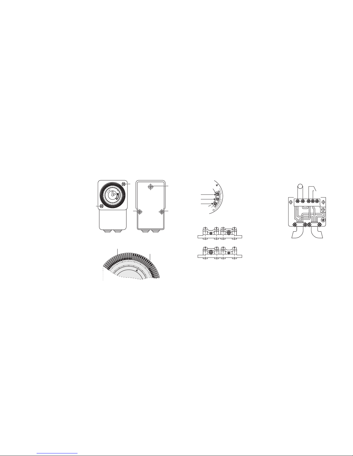
Setting up
Rotate minute hand until arrowhead on clock face,
aligns with correct time on outer dial. i. e. 8=8.00
a.m., 18=6.00 p.m. (see figure 1). When setting up
seven day version (IHT/W, GPT/W), align correct time
on outer dial, within current day sector of dial.
Note: Weekdays are printed on dial in abbreviations of
three languages.
Twenty-four hour (IHT/T, GPT/T) minimum switching
time: 15 minutes.
Seven day (IHT/W, GPT/W) minimum switching time:
2 hours.
To set ON/OFF times, move all tappets between
ON and OFF times required to outer position i.e. to
set ON at 8.00 a.m. and OFF at 11.00 a.m. move all
tappets to outer position (see figure 2): Set any other
ON/OFF times in a similar manner.
6
7
8
9
10
11
12
13
14
15
16
Wiring Example:
Immersion Heater Connections.
Fig. 1
Fig. 2
Fig. 4
Tappets in OFF position
Tappets in ON position
Manual switch - Immersion Heater Timer
(IHT/T&IHT/W) only.
The manual switch can be moved to override the timed
selection:
· In position 1 the timeswitch is permanently ON
irrespective of tappet positions.
· In position 2 the timeswitch is operating on timed
control and will switch ON and OFF as determined
by tappet positions.
· In position 3 the timeswitch is permanently OFF
irrespective of tappet positions.
· The manual switch must be returned to position 2 to
restore the timed function.
· See figure 3 for diagram of switch selections.
Manual switch - General Purpose Timer
(GPT/T and GPT/W)
The timer incorporates a changeover switch. Therefore,
when in use as a general purpose timer, the manual
switch functions as follows:
· In position 1, the timeswitch will give permanent
output on terminal 4.
· In position 2, the output will switch between
terminals 4&5, as determined by tappet positions.
· In position 3, the timeswitch will give permanent
output on terminal 5.
· The manual switch must be returned to position 2 to
restore the timed function.
80.10.1055.7/07/01
a
b
d
c
a
12
9
6
1
9
20
2
1
2
2
23
24
1
2
3
4
5
6
7
8
9
10
1
1
1
2
1
3
1
4
15
1
6
17
18
Fig. 3
1
2
3
O
I
Connections:
Mains supply Immersion Heater
1 Neutral 1 Neutral
2 Link 4 Live
3 Link + Live
Earth Earth
Link 2 to 3 provided
3 41
M
~
2 5
Mains supply
(input)
Immersion Heater
(output)
NOTE: Do not connect unprepared stranded wires to
device. Use ferrules supplied to crimp stranded wire
terminations.
 Loading...