

Grasslin Famoso 800 User Manual

1. List of contents 2
GB
1. List of contents Page
2. Elementary operator control 3
3. Installation notes 4
3.1 Installation 5 / 6
3.2 Connecting up 7
3.3 Fitting/replacing the battery 8 / 9
4. Setting the correct time 10
5. Setting the switching times 11
6. Setting the temperature levels 12
7. Manual switch/operating modes 13
8. Heating cycle setting 14 / 15
9. Reset 16
10. Technical data 17
11. Problems and remedies 18
12. Cleaning and maintenance 19
13. Service addresses 19
14.
Alphabetical subject-index
19
Grey area indicates user range
2. Elementary operator control 3
GB
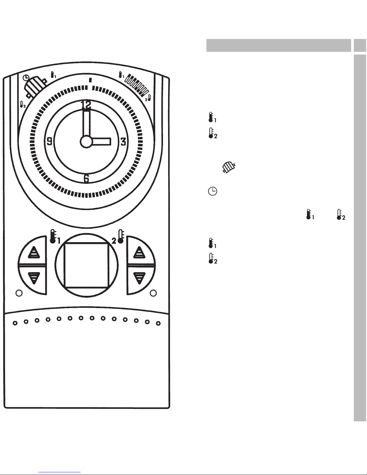
This room thermostat clock creates
comfortable room temperatures in the
simplest way possible.
The two temperature levels
= Comfort temperature
= Lower temperature
are set with the according knobs.
Settings between
5°C and 32°C possible.
The manual switch can be used to
switch between three operating modes:
Operating mode = Automatic
The unit operates during the set switching
times and switches between and .
Continuous temperature operating modes
= Comfort temperature
= Lower temperature
The selected temperature remains constant
until a different operating mode has been
selected.
Please remember when setting the
switching times that the heating system
requires a certain amount of time before
it reaches the desired temperature.
3. Installation notes 4
GB
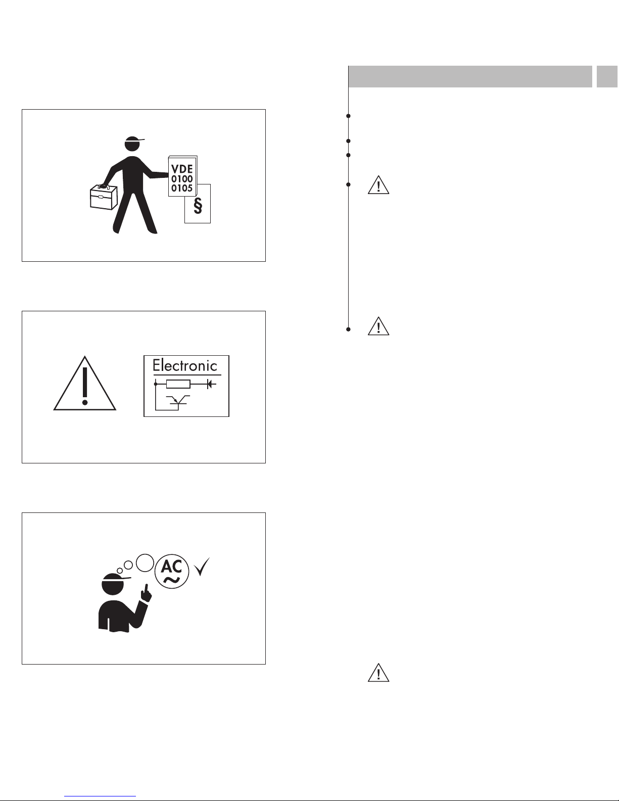
Assembly/installation should only be carried out by
qualified person exercising due care.
Switch off the heating system before assembly.
Check and make sure that the connection wires
are not live.
Assembly note:
– only use PVC-sheathed cables (solid wire)
during installation
– may only be attached to a non-conducting,
level and stable surface
– only suitable for ambient conditions where
normal quantities of dirt occur
– if installed properly in accordance with
VDE 0100, Part 40, the components where
contact remains possible may be regarded
as doubly insulated (Class of protection II)
Operating note:
This unit’s electronic unit has been protected
from external interference. However – depending
on the type of assembly – remember that the
mains voltage may be overlaid with extremely
high interference voltage peaks. Also, when
switching coils, e. g. solenoid valves, contactors,
interference occurs that may affect an electronic
unit in spite of all internal protective measures.
To guarantee the greatest operating safety, the
following details must be observed when
connecting:
– where larger plants are concerned, it will
be necessary to shield coils, e. g. solenoid
valves, contactors, that are switched directly
by the unit with a suitable varistor or
RC element
– if inductive DC voltage consumers are
switched, a free-wheeling diode must be
added
– inductive and capacitive loads especially
exert a lot of stress on the output contacts.
In individual cases check, whether the installation
requires
– an isolation relay or contactor or
– an interference suppression filter, e. g. Type
NEF 2.-1,0 A, Messrs. Murr.
Operation notes:
Pointed metal objects should not be used on
keys that need to be operated with an aid (e. g.
needles) – the rubber keys will be damaged!
3.1 Installation 5
GB
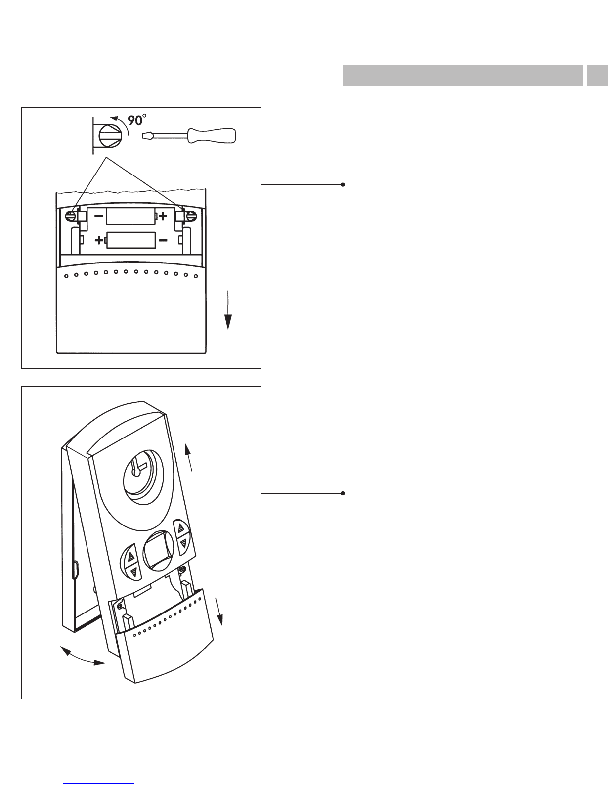
Open the battery compartment lid and
release the catch
Remove the famoso from its base
3.1 Installation 6
GB
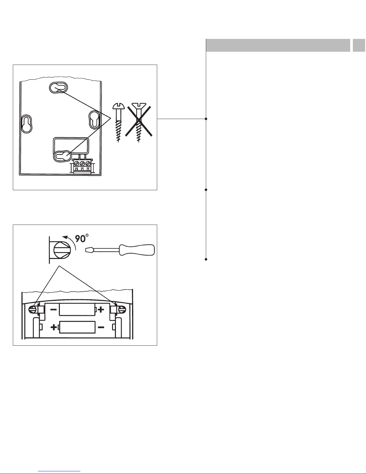
Feed the connection wires through the
opening in the unit’s base
Attach the base on a firm surface or
surface-mounted socket
Place the famoso on its base and
resecure
max.
3,5 mm
2
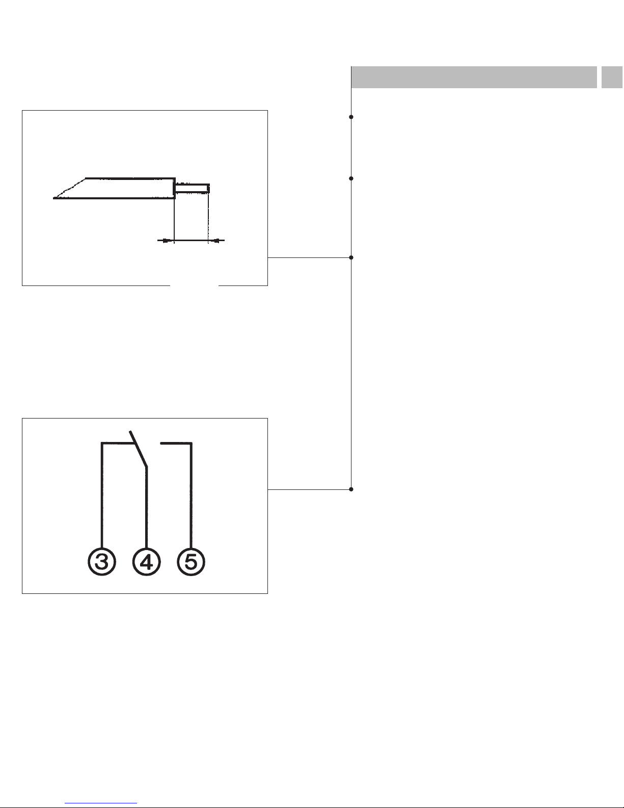
3.2 Connecting up 7
GB
The unit must be connected by a
qualifeid person exercising due care.
Check and make sure that the
connecting wires are not live.
Strip the connection wires properly
and connect as shown in the circuit
diagram.
Contacts 4-5 closed =
heating mode
max. 2,5 mm
2
max. 2,5 mm
2
mm
6
 Loading...