

Page 1
SERVICE MANUAL
D
Btx * 32700
#
Service
Manual
Sach-Nr./Part No.
72010-020.30
Zusätzlich erforderliche Unterlagen
für den
Komplettservice:
Additionally
required Service
Manuals for the
Complete Service:
8
F
Service
Manual
Sicherheit
Safety
Sach-Nr./Part No.
72010-800.00
1
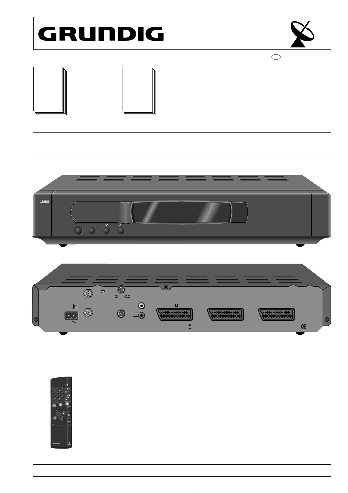
STR 631
STR 632
STR 631 (9.21629-01/G.AC 1951)
STR 632 (9.21628-01/G.AC 1851)
STR 632
À
1
LNC
MAINS
INPUT
230V
50 Hz
40W MAX.
13/18V
400mA DC
2
TP 720 SAT (29622-059.18)
3
2
1
64
5
78
9
0
TV
AV
ATS
A/B
AUX
RADIO
+
AUDIO
P
+
OK
´
-
P
F
TV
SAT
VIDEO
TP 720
SAT
CH. ADJ.
TV /VCR
AERIAL
AUDIO
OUT
L
R
TV
DO NOT REMOVE COVERS
HAZARD-LIVE PARTS
AUX1
AUX2
MADE IN U.K.
Änderungen vorbehalten Printed in Germany Service Manual Sach-Nr.
Subject to alteration VK 22 1296 Service Manual Part No. 72010-020.30
Page 2

Allgemeiner Teil / General Section STR 631 / STR 632
Es gelten die Vorschriften und Sicherheitshinweise gemäß dem Service Manual "Sicherheit",
Sach-Nummer 72010-800.00, sowie zusätzlich
die eventuell abweichenden, landesspezifischen
Vorschriften!
D
Inhaltsverzeichnis
Seite
Allgemeiner Teil ..................................1-1...1-24
Technische Daten ....................................................................... .1-3
Bedienungsanleitung ................................................................... 1-4
Ausbauhinweise......................................................................... 1-23
Servicehinweise und Sonderfunktionen..................................... 1-24
Schaltungsbeschreibung .................... 2-1…2-3
1. Audio-Signalweg ...................................................................... 2-1
2. Mikrocomputer ......................................................................... 2-1
3. Netzteil ..................................................................................... 2-2
4. Tuner........................................................................................ 2-2
5. Video Rauschfilter.................................................................... 2-2
6. LNC-Spannungsversorgung .................................................... 2-2
7. Videosignalverarbeitung .......................................................... 2-3
The regulations and safety instructions shall be
valid as provided by the "Safety" Service Manual,
part number 72010-800.00, as well as the
respective national deviations.
GB
Table of Contents
Page
General Section...................................1-1...1-24
Technical Data ............................................................................. 1-3
Operating Instructions................................................................ 1-13
Disassembly Instructions ........................................................... 1-23
Service Instructions and Special Functions ............................... 1-24
Circuit Description ............................... 2-4…2-6
1. Audio Path ............................................................................... 2-4
2. Microcomputer Operation ........................................................ 2-4
3. Power Supply........................................................................... 2-5
4. Tuner........................................................................................ 2-5
5. Video Noise Filter..................................................................... 2-5
6. LNC Power............................................................................... 2-5
7. Video Processing ..................................................................... 2-6
Platinenabbildungen
und Schaltpläne ..................................3-1...3-13
Platinenabbildungen Chassisplatte.............................................. 3-1
Schaltplan Netzteil ....................................................................... 3-7
Schaltplan Signalteil..................................................................... 3-9
Schaltplan FIP-Display............................................................... 3-13
Ersatzteillisten.......................................4-1...4-3
Allgemeiner Teil
Meßgeräte / Meßmittel
Regeltrenntrafo Meß-/Wobbelsender
Farbgenerator Oszilloskop
DC-Voltmeter NF-Voltmeter
NF-Generator Frequenzzähler
Beachten Sie bitte das Grundig Meßtechnik-Programm, das Sie unter
folgender Adresse erhalten:
Grundig electronics GmbH
Würzburger Str. 150
D-90766 Fürth/Bay.
Tel.0911/703-0
Telefax 0911/703-4479
Layout of the PCBs
and Circuit Diagrams ..........................3-1...3-13
Layout of the PCBs ...................................................................... 3-1
Circuit Diagram Power Supply ..................................................... 3-7
Circuit Diagram Signal Part.......................................................... 3-9
Circuit Diagram FIP Display....................................................... 3-13
Spare Parts Lists...................................4-1...4-3
General Part
Test Equipment / Aids
Variable isolating transformer Test/Sweep Generator
Colour Generator Oscilloscope
DC Voltmeter AF Voltmeter
AF Generator Frequency counter
Please note the Grundig Catalog "Test and Measuring Equipment"
obtainable from:
Grundig electronics GmbH
Würzburger Str. 150
D-90766 Fürth/Bay.
Tel.0911/703-0
Telefax 0911/703-4479
GRUNDIG Service1 - 2
Page 3

STR 631 / STR 632 Allgemeiner Teil / General Section
Technische Daten STR 631 / STR 632
Eingangsfrequenzbereich ........................................ 950…2150MHz
SAT-ZF-Eingänge STR 631............................................................ 1
SAT-ZF-Eingänge STR 632............................................................ 2
Scartbuchsen ....................................................... TV, AUX 1, AUX 2
Videoausgang ........................................................................... 1Vss
Audioausgang ..................................................................... 2x Cinch
Programmspeicherplätze STR 631............................................. 200
Programmspeicherplätze STR 632............................................. 300
Anzeige STR 631................................. 2 x LED, 3 x 7-SEG-Anzeige
Anzeige STR 632........................... 10-stellige, Matrix-Anzeige (FIP)
Ton-Deemphasis................................................ PANDA, 50µs / J17
Audiofrequenzgang............................................40Hz…18kHz ±2dB
ZF-Bandbreite umschaltbar ................................................... 27MHz
LNC-Power .............................................. +13V / +18V max. 400mA
Specifications STR 631 / STR 632
Input frequency range .............................................. 950…2150MHz
SAT IF-inputs STR 631................................................................... 1
SAT IF-inputs STR 632................................................................... 2
Scart sockets ....................................................... TV, AUX 1, AUX 2
Video output.............................................................................. 1Vss
Audio output........................................................................ 2x Cinch
Programme memory locations STR 631 ..................................... 200
Programme memory locations STR 631 ..................................... 300
Anzeige STR 631................................... 2 x LED, 3 x 7-SEG-display
Display STR 632 .................................10-place, Matrix display (FIP)
Sound de-emphasis ........................................... PANDA, 50µs / J17
Audio Response................................................. 40Hz…18kHz ±2dB
IF bandwidth, switchable........................................................ 27MHz
LNC power ............................................... +13V / +18V max. 400mA
Modulator-Ausgangskanal STR 631 ................................. K32…K42
Modulator-Ausgangskanal STR 632 ................................. K21…K69
Netzspannung............................................................... 185V…265V
Netzfrequenz........................................................................ 50/60Hz
Fernbedienung...............................................................TP 720 SAT
Abmessungen (BxHxT).................................. ca. 400 x 70 x 235mm
Gewicht .................................................................................. ca. 2kg
Leistungsaufnahme.............................................................. ca. 22W
Modulator output channel STR 631 ..............................Ch32…Ch42
Modulator output channel STR 632 ..............................Ch21…Ch69
Mains supply ................................................................. 185V…265V
Mains frequency................................................................... 50/60Hz
Remote control handset .................................................TP 720 SAT
Dimensions (WxHxD)..................................... ca. 400 x 70 x 235mm
Weight.................................................................................... ca. 2kg
Power Consumption............................................................. ca. 22W
GRUNDIG Service 1 - 3
Page 4
Allgemeiner Teil / General Section STR 632
1 - 4 GRUNDIG Service
Bedienhinweise Hinweis: Dieses Kapitel enthält Auszüge aus der Bedienungsanleitung. Weitergehende Informationen entnehmen Sie bitte der gerätespezifischen Bedienungsanleitung, deren
Sachnummer Sie in der entsprechenden Ersatzteilliste finden.
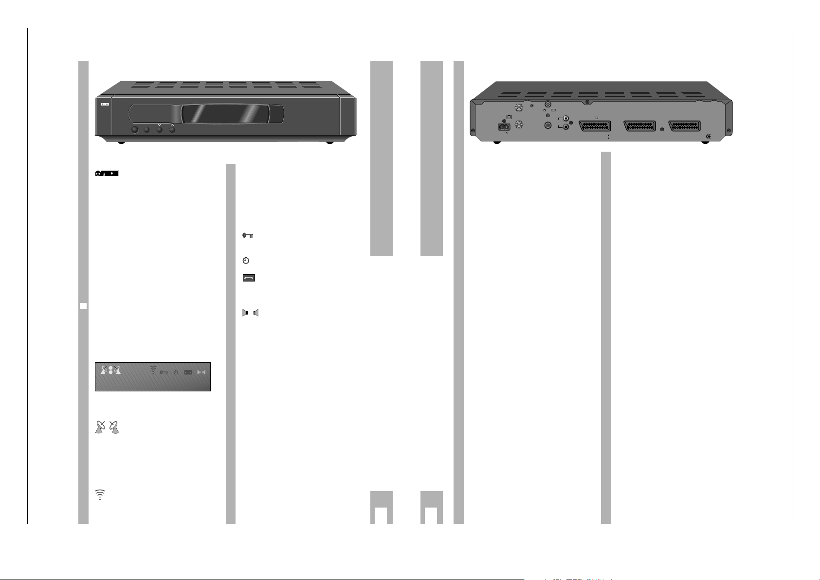
j
Tasten und Anschlüsse am Receiver
PANDA-Logo der Panda/Wegener Communications Inc.. Auszeichnung für
höchste Tonqualität.
¢
8
Schaltet den Receiver in Bereitschaft
(Keine Netztrennung!) bzw. von Bereitschaft zum zuletzt gewählten Programmplatz (Last Station Memory).
¢
F
Umschalten der Betriebsart zwischen
den verschiedenen Programmtabellen:
Normal-, Radio- und Favorit-Tabellen.
¢
% Programmplätze schrittweise – abwärts
– fortschalten (länger drücken: Schnelldurchlauf).
¢
& Programmplätze schrittweise – aufwärts
– fortschalten (länger drücken: Schnelldurchlauf).
Rechts neben der Anzeige am Gerät befindet sich
der Empfänger für die Infrarotsignale der Fernbedienung.
Die Anzeige des Receivers auf
einen Blick
Gibt den Antenneneingang an
(LNC 1 oder 2), der für den aktuellen Programmplatz gewählt ist.
1
A
22 kHz Schaltspannung am aktuellen LNC-Eingang ausgeschaltet.
1
B
22 kHz Schaltspannung am aktuellen LNC-Eingang eingeschaltet.
Ku BAND SAT Ku-Band Kanäle
Der Receiver empfängt
Fernbedienbefehle.
2
1
B
TUNER
21
Ku BANDC
A
INT
DECODER
TXE
NRS
1
2
21 EURO
6
ADNAP
DECODER EXT Für den aktuellen Programmplatz
wird gemäß den Einstellungen im
Menü ein externer Decoder
benötigt.
NRS In der Tonauswahl ist das Panda
Wegener Rauschunterdrückungssystem (Noise Reduction System)
eingestellt.
Der eingestellte Programmplatz
ist über das Zahlenschloß
gesperrt.
(Mindestens) einer der Timer ist
in Bereitschaft oder aktiv.
An der EURO-AV-Buchse »VCR«
ist ein Videorecorder angeschlossen, der derzeit in Betrieb ist.
Der Receiver ist im VCR-Betrieb.
Stereo (beide Lautsprechersym-
bole leuchten),
Mono (nur das rechte Lautsprechersymbol leuchtet).
OOOOOOOOOO 10-stellige Multifunktionsanzeige
(z.B. Demo Mode, Senderbezeichnung, Mitteilungen)
STR 632
À
F
1
8
Gerätevorderseite
Geräterückseite
MAINS INPUT Anschluß für steckbares Netzkabel.
LNC 1 LNC-Anschluß für Satelliten-
antenne(n).
LNC 2 LNC-Anschluß für weitere Satelliten-
antenne(n).
CH. ADJ. ohne Funktion.
AERIAL Terrestrischer Antenneneingang
(VHF/UHF).
TV/VCR Modulator-Antennenausgang
(VHF/UHF).
AUDIO OUT NF-Stereo-Ausgang,
linker (L) und rechter (R) Kanal.
TV EURO-AV-Buchse zum Anschluß
eines TV-Gerätes.
AUX 2 EURO-AV-Buchse zum Anschluß
eines Videorecorders.
AUX 1 EURO-AV-Buchse zum Anschluß
eines externen Decoders.
j
Tasten und Anschlüsse am Receiver
1
CH. ADJ.
TV /VCR
LNC
MAINS
13/18V
INPUT
400mA DC
2
230V
50 Hz
40W MAX.
AERIAL
AUDIO
OUT
TV
L
R
DO NOT REMOVE COVERS
HAZARD-LIVE PARTS
AUX1
AUX2
MADE IN U.K.
Page 5
STR 632 Allgemeiner Teil / General Section
GRUNDIG Service 1 - 5
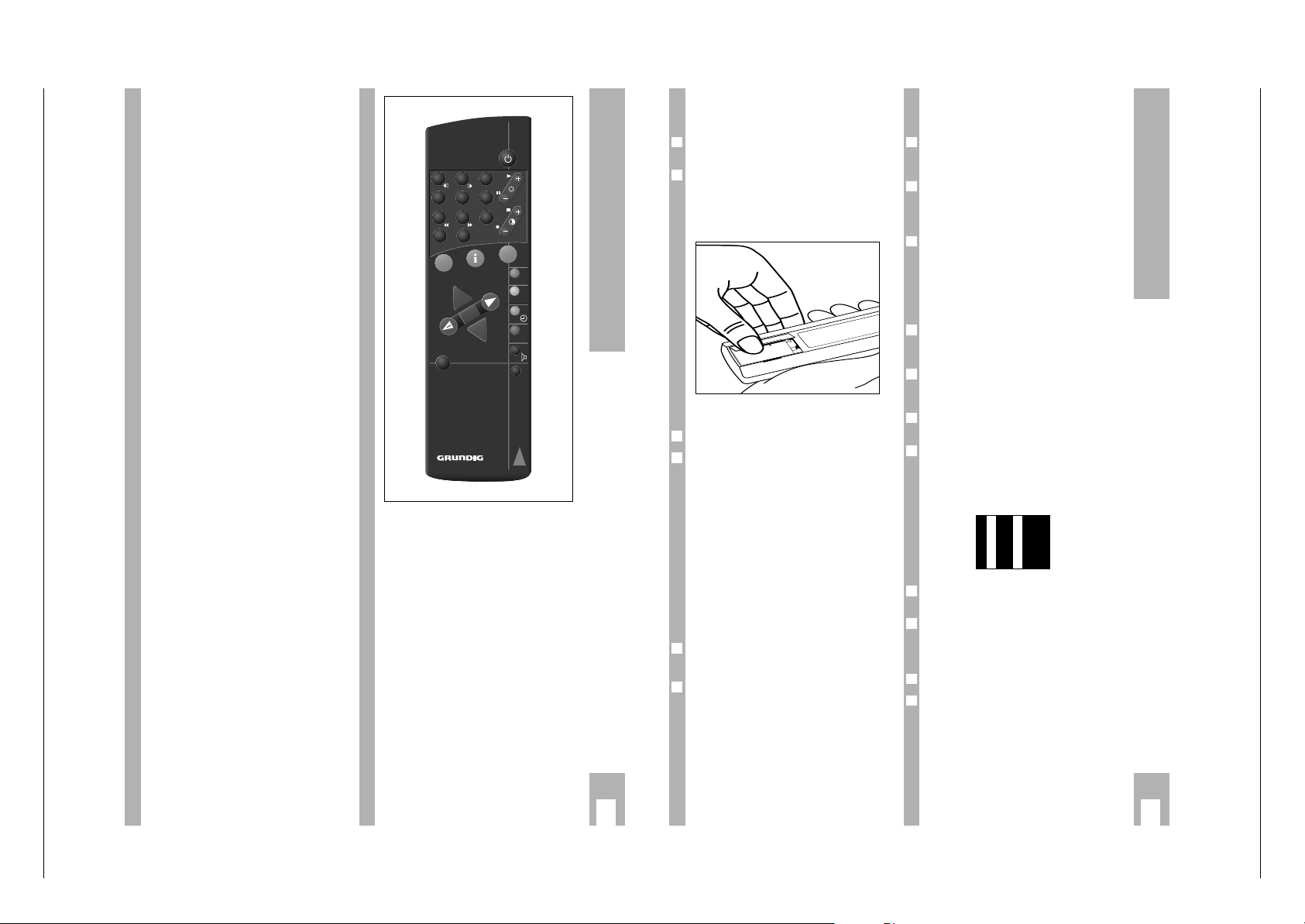
b
Schaltet den Receiver in Bereitschaft
(stand-by) bzw. von Bereitschaft wieder
zum zuletzt gewählten Programmplatz.
1… 0
Wählt die Programmplätze direkt;
Eingabe von Daten im Menü.
]
Wählt Programmplätze schrittweise –
aufwärts (länger drücken: Schnelldurchlauf) .
Wählt im Menü Daten an.
|
Wählt Programmplätze schrittweise –
abwärts (länger drücken: Schnelldurchlauf).
Wählt im Menü Daten an.
x c
Lautstärkeeinstellung ändern, verändert
Einstellungen.
.
- Ruft die Statusanzeige auf (1x drücken),
- Ruft die Menüführung auf (2x drücken),
- Schaltet in der Menüführung zum
nächsthöheren Menü bzw. beendet das
Hauptmenü. Änderungen werden dabei
nicht gespeichert.
,
A/B
Umschalten zwischen SAT-, VCR- und
TV-Mode (siehe Abschnitt “Umschalten
zwischen SAT-, TV- und VCR-Betrieb”
im Kapitel “Bedienen”).
Im Menü: Umschalten zwischen blauem
Bildschirmhintergrund und TV-Bild im
Hintergrund.
¢
F
Schaltet zwischen den Programmtabellen um: Normal-Betrieb, Radio-Betrieb
und FAVORIT-Betriebsarten (bevorzugte
Kanäle).
¢
AUDIO
Aufrufen der Audioübersicht.
¢
´
Aufrufen der Kanalübersicht (Programmplatzübersicht).
¢
RADIO
Ohne Funktion.
O Bestätigt/speichert Einstellungen;
aus Bereitschaft: Menü zur UHF-Kanaleinstellung öffnen (etwa 6 Sekunden
drücken).
¢
TV
/ATS
Ohne Funktion.
¢
+
Stummschalten bei SAT-Betrieb
(»MUTE« erscheint auf dem Bildschirm).
j
Die Tasten der Fernbedienung
Batterie in die Fernbedienung
einlegen
Setzen Sie die Batterie gemäß Skizze ein (Polung
beachten! Markierung hierfür am Fachboden).
Wenn Ihr Receiver auf die Fernbedienbefehle nicht
mehr reagiert, kann die Batterie verbraucht sein.
w
!
Verbrauchte Batterie unbedingt entfernen.
Für Schäden, die durch eine ausgelaufene Batterie
entstehen, kann nicht gehaftet werden.
Einschalten
Schalten Sie das Fernsehgerät ein.
Schalten Sie den Receiver mit einer der Tasten
¢
8
,
¢
% oder ¢& am Receiver oder einer der Tasten
b
, ]oder |der Fernbedienung ein.
– Das zuletzt eingestellte Programm erscheint auto-
matisch (Last Station Memory)
oder
geben Sie mit den Zifferntasten 0… 9der Fernbe-
dienung die Nummer des gewünschten Programmplatzes direkt ein.
– Der Receiver schaltet sich automatisch mit der
zuletzt gewählten Sendertabelle (FAVORIT-Tabel-
len, Radio-Tabelle oder Normal-Tabelle) ein.
Ausschalten
Drücken Sie die Taste bder Fernbedienung oder
die Taste
¢
8
an der Vorderseite des Receivers, um
das Gerät auszuschalten.
In der Anzeige des Receivers erscheint »Bereit
8
«, wenn sich der Receiver in Bereitschaft (standby) befindet.
w
!
Keine Netztrennung, wenn der Netzstecker nicht
gezogen ist (siehe Kapitel "Aufstellen und Sicherheit").
6
1
2
1
+
-
9V
6
1
j
Fernsehgerät und Videorecorder
auf den Receiver abstimmen
Diese Einstellung kann entfallen, wenn der Receiver
über ein EURO-AV-Kabel mit dem Fernsehgerät
oder dem Videorecorder verbunden ist.
Wählen Sie an Ihrem Fernsehgerät einen freien Programmplatz und stellen den UHF-Kanal 37 (Ausgangskanal des Receivers) gemäß Bedienungsanleitung Ihres Fernsehgerätes ein.
Sollte dieser Kanal bereits durch einen Fernsehkanal oder ein anderes Gerät (z.B. Ausgang eines
Videorecorders) belegt sein, sehen Sie Störungen
(wenn das andere Gerät eingeschaltet ist).
Stellen Sie in diesem Fall den Programmplatz Ihres
Fernsehgerätes auf einen freien Kanal im Bereich 21
bis 69 ein.
Schalten Sie den Receiver mit der Taste ban der
Fernbedienung oder Taste
¢
8
am Gerät in Bereit-
schaft.
Drücken Sie etwa 6 Sekunden die Taste O der
Fernbedienung. In der Anzeige des Receivers
erscheint »K 37«.
Wählen Sie mit den Tasten cund x oder den Zifferntasten den am Fernsehgerät eingestellten Kanal.
Am Modulatorausgang »TV/VCR« (an der Rückseite des Receivers) wird in diesem Betriebszustand
ein Testbild ausgegeben. Es hilft Ihnen, den entsprechenden Kanal am TV-Gerät einzustellen. Dies
ist auch ohne Satellitenempfang möglich.
Optimieren Sie Bild und Ton über die Feineinstellung Ihres Fernsehgerätes.
Mit der Taste O speichern Sie die Einstellung, der
Receiver schaltet wieder in Bereitschaft. Mit der
Taste .können Sie die Eingabe abbrechen, der
vorherige Wert wird wieder gültig.
Das Testbild wird nicht mehr ausgegeben.
Stellen Sie auf die gleiche Weise auch einen freien
Programmplatz Ihres Videorecorders auf den
Receiverausgang ein.
8
6
7
6
6
5
4
3
2
1
6
Vorbereiten
1 2 3
4 5 6
7 8 9
0
TV
AV
ATS
AUX
+
P
OK
TV
SAT
A/B
k
RADIO
AUDIO
+
-
P
F
VIDEO
TP 720
SAT
Page 6
Allgemeiner Teil / General Section STR 632
1 - 6 GRUNDIG Service
Allgemeine Beschreibung der
Menüführung
Wenn Sie die Taste .der Fernbedienung einmal
drücken, erscheint auf dem Bildschirm des Fernsehgerätes kurzzeitig die Statusanzeige.
Sie beinhaltet: die Angabe der aktiven Programmtabelle (z.B. Favorit DEUTSCH), die Programmplatznummer und den Namen des gewählten Senders,
Programmplatzeinstellungen (Sendefrequenz des
Satelliten, Polarisation und die gewählte Audio-Einstellung), Wochentag und Uhrzeit.
Drücken Sie zweimal die Taste .der Fernbedienung.
– Das »HAUPTMENUE« erscheint.
Sie können mit den Zifferntasten Untermenüs aufrufen.
Sie können mit den Tasten ]|Daten anwählen,
die Sie ändern wollen.
Mit den Tasten xc(bei manchen Menüfunktionen auch mit den Zifferntasten) können Sie die
Daten ändern.
Speichern Sie die vorgenommenen Änderungen mit
der Taste O.
Falls Sie mit der Bildschirmanzeige »SICHER?«
dazu aufgefordert werden, müssen Sie erneut mit
der Taste O bestätigen, daß Sie die Einstellungen
wirklich speichern wollen. Hierauf wird im weiteren
nicht mehr ausdrücklich hingewiesen.
Drücken Sie im Menü die Taste
,
A/B
, um das TV-
Bild ein- bzw. auszublenden.
Um ein Menü zu beenden, drücken Sie die Taste ..
Sie gelangen von einem Untermenü zum Hauptmenü bzw. verlassen das Menü ohne zu speichern.
8
7
6
5
4
3
2
1
Sprachwahl
Für die Bildschirmmenüs haben Sie die Auswahl
zwischen den folgenden Sprachen:
»ENGLISH«
»DEUTSCH«
»ESPANOL«
»PORTUGUES«
»ITALIANO«
Drücken Sie zweimal die Taste .der Fernbedie-
nung.
– Das »HAUPTMENUE« erscheint.
Drücken Sie die Zifferntaste 2und anschließend
die Zifferntaste 4.
– Nacheinander erscheinen die Menüs
»INSTALLATION« und »SPRACHWAHL«.
Wählen Sie mit den Zifferntasten 1bis 5die
gewünschte Sprache.
– Die gewählte Sprache wird automatisch gespei-
chert.
3
2
1
j
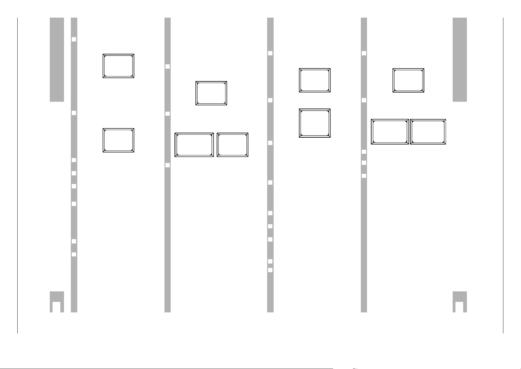
Einstellungen
HAUPTMENUE
1 TIMER
2 INSTALLATION
3 KANALEINSTELLUNG
4 ZAHLENSCHLOSS
I BEENDEN
STATUS
001 ARD
11494 GHZ H
7.02 7.20 MHZ PANDA
DI 15:35
INSTALLATION
1 GRUNDEINSTELLUNGEN LNC
2 AUDIO EINSTELLUNG
3 DECODER/AV
4 SPRACHWAHL
I BEENDEN
SPRACHWAHL
1 ENGLISH
2 DEUTSCH
3 ESPANOL
4 PORTUGUES
5 ITALIANO
I BEENDEN
HAUPTMENUE
1 TIMER
2 INSTALLATION
3 KANALEINSTELLUNG
4 ZAHLENSCHLOSS
I BEENDEN
j
Einstellungen
Uhrzeit und Datum einstellen
Bei der Inbetriebnahme und nach einem Stromausfall muß das Datum und die Uhrzeit eingestellt
werden, um eine korrekte Funktion des Timers zu
gewährleisten.
Drücken Sie zweimal die Taste .der Fernbedienung.
– Das »HAUPTMENUE« erscheint.
Drücken Sie die Zifferntaste 1.
– Das Menü »TIMER« erscheint.
Drücken Sie die Taste |so oft, bis die Stundenanzeige hinter dem Begriff »ZEIT« blinkt.
Geben Sie aktuelle Uhrzeit (Stunden) ein, verwenden Sie dazu
die Zifferntasten oder
die Tasten xc, drücken Sie danach die
Taste |.
Die Minutenanzeige blinkt.
Geben Sie die Minuten ein, verwenden Sie dazu
die Zifferntasten oder
die Tasten xc, drücken Sie danach die
Taste |.
Die Angabe des Wochentags blinkt.
Wählen Sie mit den Tasten xcden Wochentag.
Mit Taste ]gelangen Sie zur jeweils vorhergehenden Einstellung zurück.
Überprüfen Sie bitte, ob der Timerstatus »AUS« ist.
Ist der Timerstatus »EIN«, wählen Sie mit der Taste
]
die Einstellung »STATUS« und schalten Sie den
Timer mit der Taste xoder caus.
Speichern Sie die Einstellung mit Taste O.
Beenden Sie die Einstellung, dazu Taste .zweimal
drücken.
8
7
6
6
5
4
3
2
1
LNC-Abgleich
Ihr Receiver muß auf das verwendete LNC abgestimmt werden.
Schalten Sie den Receiver ein und wählen einen
Programmplatz mit gutem Empfang.
Drücken Sie zweimal die Taste .der Fernbedienung.
– Das »HAUPTMENUE« erscheint.
Drücken Sie die Zifferntaste 2und anschließend
die Zifferntaste 1.
– Nacheinander erscheinen die Menüs »INSTALLATION« und »GRUNDEINSTELLUNGEN LNC«.
Drücken Sie die Taste
,
A/B
, um das TV-Bild ein-
bzw. auszublenden.
Mit der Taste |(bzw. ]) können Sie den jeweils
nächsten (bzw. vorherigen) Menüpunkt anwählen.
Sie können zwischen 4 LNC-Typen wählen
Die Einstellung LNC-Typ 1 ist für ein einzelnes LNC
mit nur einer Oszillatorfrequenz vorgesehen.
Die Einstellung LNC-Typ 2 ist für Universal-LNCs
vorgesehen. Durch die Ausgabe eines 22 kHz
Schaltsignals an das LNC schaltet dieses zwischen
zwei Frequenzbereichen um (A: Schaltsignal aus unterer Frequenzbereich, B: Schaltsignal ein – oberer Frequenzbereich). Das 22 kHz Schaltsignal kann
auch genutzt werden, um mit einem Umschaltrelais
oder einem Multischalter zwischen zwei LNCs
umzuschalten. Die zur Eingabe benötigten LNC-Frequenzen gehen aus der Beschreibung Ihres LNCs
hervor.
LNC-Steuerung mittels DiSEqC-Signalen
Bei der Einstellung LNC-Typ 3 und 4 wird die
zukunftsorientierte digitale LNC-Steuerung mittels
sogenanntem DiSEqC-Signal (Digital Satellite
Equipment Control) genutzt. Die verwendete Antennenanlage muß in diesem Fall ebenfalls für DiSEqC
ausgelegt sein.
6
4
3
2
1
HAUPTMENUE
1 TIMER
2 INSTALLATION
3 KANALEINSTELLUNG
4 ZAHLENSCHLOSS
I BEENDEN
TIMER 1
STATUS AUS
LISTE NORMAL
KANAL 001 ARD
WOCHE 1
TAG MO
START 20:15
STOP 22:00
ZEIT 18:00 MO
DRUECKE OK ODER I
HAUPTMENUE
1 TIMER
2 INSTALLATION
3 KANALEINSTELLUNG
4 ZAHLENSCHLOSS
I BEENDEN
INSTALLATION
1 GRUNDEINSTELLUNGEN LNC
2 AUDIO EINSTELLUNG
3 DECODER/AV
4 SPRACHWAHL
I BEENDEN
GRUNDEINSTELLUNGEN LNC
LNC1 LNC2
LNC-TYP 2 2
SPANNUNG EIN EIN
GHZ (A) 09.750 10.000
GHZ (B) 09.750 09.750
22KHZ A:AUS B:EIN
DRUECKE OK ODER I
Page 7
STR 632 Allgemeiner Teil / General Section
GRUNDIG Service 1 - 7
Sie können die LNC-Frequenz(en) 5-stellig mit den
Zifferntasten eingeben, oder mit den Tasten
xc
den aktuellen Wert schrittweise verringern oder
erhöhen.
w
!
Erscheint in der Anzeige des Receivers z.B. der
Sender RTL 2, wenn Sie ZDF gewählt haben,
stimmt die Oszillatorfrequenz nicht mit dem verwendeten LNC überein. Verändern Sie in diesem
Fall die LNC-Frequenz mit den Zifferntasten von
9.750 auf 10.000.
w
!
Ist die Frequenz nicht exakt eingestellt, weist das
TV-Bild kleine schwarze oder weiße Striche auf.
Stellen Sie die Frequenz so ein, daß diese Striche
verschwinden bzw. minimiert werden.
Wenn Sie die LNC-Oszillatorfrequenz erhöhen,
verringert sich die Anzahl der weißen Striche, wenn
Sie die Frequenz verringern, beseitigen Sie die
schwarzen Striche.
Wiederholen Sie diese Einstellung (6), falls nötig,
für die zweite LNC-Frequenz.
Wiederholen Sie die Einstellungen (5 und 6) für
LNC2.
Speichern Sie die Einstellungen mit Taste O.
Beenden Sie die Einstellung, dazu Taste .zweimal
drücken.
Für jeden Programmplatz muß das richtige LNC
ausgewählt werden (siehe Abschnitt “Programm
platzeinstellungen ändern/LNC auswählen” im
Kapitel “Bedienen”).
6
10
9
8
7
6
6
j
Einstellungen
Bei LNC-Typ 3 kann ein Universal-(Mehrbereichs-)
LNC mit DiSEqC-Steuerung zwischen horizontal
und vertikal polarisiertem Signal (H und V) und
zwischen oberem und unterem Frequenzbereich (A
und B) umgeschaltet werden. Die beiden Oszillatorfrequenzen (oberer und unterer LNC-Bereich) sind
einzugeben.
Bei LNC-Typ 4 kann mit DiSEqC-Steuerung zwischen 2 DUAL- oder QUATTRO-LNCs (Einstellung
»OST« bzw. »WEST«), zwischen horizontal und
vertikal polarisiertem Signal (H und V) und
zwischen oberem und unterem Frequenzbereich
(A und B) umgeschaltet werden. Im oberen
Frequenzbereich wird auch das 22 kHz Signal ausgegeben. Die beiden Oszillatorfrequenzen (oberer
und unterer LNC-Bereich für beide LNCs) sind einzugeben.
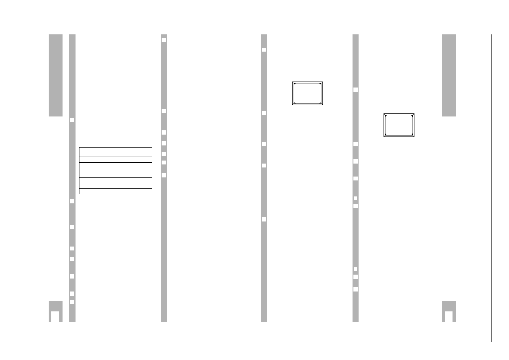
Eine Übersicht der Vorprogrammierung des
STR 632 für die verschiedenen Satelliten gibt die
folgende Tabelle. Wenn Sie die Antennen anders
anschließen wollen als vorgegeben, müssen Sie die
LNC-Auswahl bei allen betroffenen Programmplätzen korrigieren.
Verwenden Sie deshalb bitte den Anschluß LNC 1
um Astra zu empfangen und den Anschluß LNC 2
um einen der anderen vorprogrammierten Satelliten
zu empfangen (siehe auch Kapitel “Mehrsatellitenempfang”).
Wie Sie für den jeweiligen Programmplatz die LNCAuswahl (z.B. 22 kHz Schaltspannung ein oder aus)
vornehmen können, finden Sie in Abschnitt
“Programmplatz einrichten”.
Wählen Sie mit den Tasten xcjeweils den
gewünschten LNC-Typ.
Unter dem Menüpunkt »SPANNUNG EIN/AUS«
können Sie mit den Tasten xoder cdie Stromversorgung für das LNC an- und abschalten.
Die Einstellung “Spannung AUS” benötigen Sie z.B.
für eine Einkabellösung mit mehreren angeschlossenen Receivern.
Werkseitig ist “SPANNUNG EIN” voreingestellt.
Die LNC-Oszillatorfrequenz ist auf 09.750 GHz vor-
eingestellt. Verwenden Sie ein anderes LNC, ist der
Wert zu korrigieren.
6
6
6
6
5
6
6
6
Satellit vorprogrammierte
LNC-Einstellung
Astra 1A (Ausgang LNC 1, 0 kHz)
Eutelsat II F1/
Hotbird 2A (Ausgang LNC 2, 0 kHz)
Eutelsat II F2 2A (Ausgang LNC 2, 0 kHz)
Hispasat 2A (Ausgang LNC 2, 0 kHz)
Telecom 2B 2A (Ausgang LNC 2, 0 kHz)
Telecom 2A 2A (Ausgang LNC 2, 0 kHz)
j
Bedienen
Statusanzeige
Wenn Sie die Taste .einmal drücken, erscheint
kurzzeitig auf dem Bildschirm des Fernsehgerätes
eine Statusanzeige mit dem Namen der gewählten
Sendertabelle, Programmplatznummer, Sendername, Frequenz und Polarisation des Senders, Angabe der Toneinstellung, Uhrzeit und der Option zum
Aufrufen des Hauptmenüs (mit .).
In der Anzeige des Receivers erscheint nacheinander die Frequenz und Polarisation des aktuellen
Senders und der Sendername.
Gespeicherte Sendertabellen
Der Receiver ist bereits auf die aktuellen Programme vieler Satelliten vorprogrammiert (siehe Programmtabelle), eine Korrektur ist in den meisten
Fällen nicht nötig.
Sie können selbstverständlich auch Programme
empfangen, die nicht im Receiver vorprogrammiert
sind (siehe dazu Kapitel "Programmplatz einrichten").
Wie Sie sich Sendertabellen nach Ihren Wünschen
zusammenstellen können, finden Sie im Kapitel
"Bevorzugte Satellitensender auswählen".
Nach dem Einschalten aus Bereitschaft sind die
Betriebsart und der Programmplatz aktiv, die vor
dem Ausschalten eingestellt waren (Last Station
Memory).
Sie können zwischen 7 Sendertabellen wählen:
NORMAL:
In dieser Sendertabelle sind alle vorprogrammierten Sender gespeichert. Wenn Sie Einstellungen der
Programmplätze ändern wollen, so erfolgt dies
immer in der Sendertabelle NORMAL.
FAVORIT/RADIO:
Damit Sie Ihre Lieblingsprogramme schnell über
die niedrigsten Programmplätze anwählen können,
ohne die Gesamtsendertabelle umsortieren zu müssen, können Sie bevorzugte Programmplätze über
die Favorit-Sendertabellen anwählen. Diese enthalten eine Auswahl der Normal-Tabelle.
Die 5 Favorit-Sendertabellen sind mit den jeweils
20 “interessantesten” Sendern einer Sprachgruppe
(englisch, deutsch ...) vorprogrammiert und mit der
jeweiligen Sprache bezeichnet. Die Radio-Sendertabelle ist für 20 Radiosender vorgesehen. Sie verhält sich ebenso wie die anderen Favorit-Sendertabellen.
6
6
6
6
6
Sie können die Bezeichnung der Favorit-Sendertabellen, die enthaltenen Programme und deren Reihenfolge nach Ihren Wünschen ändern. Bis zu fünf
Personen können jeweils ihre eigene Favorit-Tabelle
zusammenstellen und mit einem Namen benennen
(siehe ”Bevorzugte Satellitensender auswählen“).
Wahl der Sendertabelle und des
Programmplatzes
Mit der roten Taste
¢
F
der Fernbedienung oder der
Taste
¢
F
am Receiver können Sie zwischen den
verschiedenen Sendertabellen (Normal- Radio- und
den aktiven Favorit-Sendertabellen) umschalten
(Taste mehrmals drücken).
Für jede Sendertabelle wird der jeweils zuletzt
eingeschaltete Programmplatz automatisch wieder
eingestellt (Last Station Memory).
Auf dem Bildschirm wird die ausgewählte Sendertabelle, die Nummer und die Bezeichnung des aktuellen Programmplatzes angezeigt.
Mit den Tasten
]
|
oder den Zifferntasten können Sie einen anderen Programmplatz
der aktuellen Sendertabelle wählen.
❒
Programmplatz schrittweise anwählen
Mit den Tasten
]
|
der Fernbedienung oder den
Tasten
¢
% oder ¢& am Receiver können Sie die
Programmplätze schrittweise anwählen.
– In der Anzeige des Receivers erscheint nachein-
ander die Senderbezeichnung, die Bezeichnung
der gewählten Sendertabelle und erneut die Senderbezeichnung. Ist die Tabelle »NORMAL«
gewählt, erscheint hinter »NORMAL« die Programmplatznummer.
– Kurzzeitig werden die Bezeichnung der Sender-
tabelle, die Programmplatznummer und die
Senderbezeichnung auch auf dem Bildschirm des
Fernsehgerätes eingeblendet.
❒
Programmplatz direkt anwählen
Wählen Sie die Programmplätze 1 bis 9 mit den
Zifferntasten 1bis 9an.
Für die Programmplätze 10 bis 300 geben Sie den
Programmplatz mit den Zifferntasten zwei- bzw.
dreistellig ein.
Beachten Sie, daß die mehrstellige Eingabe innerhalb von 2 Sekunden erfolgen muß.
2
1
1
2
6
6
1
DEUTSCH FO1 ARD
STATUS
001 ARD
11494 GHZ H
7.02 7.20 MHZ PANDA
DI 15:35
Page 8
Allgemeiner Teil / General Section STR 632
1 - 8 GRUNDIG Service
Einstellen der Lautstärke
Wenn Sie eine der Tasten xoder cdrücken, wird
ein Menü zum Ändern der Lautstärke aufgerufen.
In der Anzeige des Receivers erscheint z.B.
»LAUTST. 24«
Die Lautstärkeeinstellung wirkt sich nur auf die
Ausgänge »TV/VCR«, »AUDIO OUT« und die
EURO-AV-Buchse »TV« aus, hat also keinen
Einfluß auf die EURO-AV-Buchsen für Videorecorder (AUX 2) und Decoder (AUX 1).
Sie können die Lautstärke mit den Tasten xczwischen 0 und 32 einstellen.
Speichern Sie den Wert mit O ab, dann bleibt er
dauerhaft erhalten.
Mit .können Sie die Einstellung rückgängig
machen, wenn Sie noch nicht gespeichert ist.
Wenn Sie weder .noch O drücken, wird das
Menü nach einigen Sekunden verlassen. Der eingestellte Wert bleibt gültig, bis Sie den Receiver in
Bereitschaft schalten, danach wird der vorhergehende Wert wieder angenommen.
Stummschalten (MUTE)
Mit der Taste
¢
+
können Sie das Gerät im
SAT-Betrieb stummschalten, mit der selben Taste
schalten Sie den Ton wieder ein.
Rechts oben auf dem Bildschirm erscheint
»MUTE«, solange das Gerät stummgeschaltet ist.
Kanalübersicht
(Programmplatzübersicht)
Mit der grünen Taste
¢
´
rufen Sie direkt
die »KANALUEBERSICHT« zum Auswählen von
Programmen auf. Das erleichtert es Ihnen ein
Programm zu finden, von dem Sie die Programmplatznummer nicht kennen.
In der Anzeige des Receivers erscheint »UEBER-
SICHT«.
6
1
6
1
3
2
6
6
1
Die aktive Sendertabelle wird direkt unterhalb der
Kopfzeile angezeigt.
Der gewählte Programmplatz erscheint in der dritten Auswahlzeile, die Ziffer 3 blinkt. Mit den Zifferntasten 1… 5oder den Tasten
]
|
können Sie
eine andere Einstellung wählen. Mit der Zifferntaste
0
können Sie seitenweise “weiterblättern”. Die
erste Zeile ist dann jeweils aktiv (die Ziffer 1 blinkt).
Mit der grünen Taste
¢
´
können Sie die
»KANALÜBERSICHT« wieder ausblenden. Wenn
Sie einige Sekunden keine Taste drücken, wird sie
automatisch wieder ausgeblendet.
Bevorzugte Satellitensender
auswählen
In den fünf »FAVORIT-Sendertabellen« und der
»Radio-Sendertabelle« können Sie sich aus den
Programmplätzen der Sendertabelle NORMAL (in
der alle vorprogrammierten Sender enthalten sind)
Ihre persönlichen Lieblingsprogramme zusammenstellen. 20 Programmplätze stehen dafür jeweils zur
Verfügung.
In der beiliegenden Sendertabelle finden Sie eine
Liste der werkseitig eingestellten Kanäle.
Drücken Sie zweimal die Taste .der Fernbedienung.
– Das »HAUPTMENUE« erscheint.
Drücken Sie die Zifferntaste 3und dann die Zifferntaste 2.
– Das Menü »FAVORITEN TABELLE« erscheint
(Favorit - Bevorzugte Programmplätze) mit den
ersten 5 bevorzugten Programmplätzen.
Die Zahl hinter dem Namen der Favoriten-Tabelle
blinkt. Mit den Tasten xckönnen Sie zwischen
den verschiedenen Favoriten-Tabellen und der
Radio-Tabelle umschalten.
Mit den Tasten |und ]können Sie die einzelnen
Zeichen/Buchstaben des Namens der aktuellen
Tabelle anwählen und mit den Tasten xcändern.
3
2
1
6
6
3
2
6
j
Bedienen
HAUPTMENUE
1 TIMER
2 INSTALLATION
3 KANALEINSTELLUNG
4 ZAHLENSCHLOSS
I BEENDEN
KANALEINSTELLUNG
1 BILD
2 FAVORITEN TABELLEN
I BEENDEN
FAVORITEN TABELLE
NAME DEUTSCH.2
AKTIV EIN
F01 001 ARD
F02 002 ZDF
F03 003 RTL
F04 004 SAT 1
F05 005 N-TV
DRUECKE OK ODER I
LAUTSTAERKE
24
DRUECKE OK ODER I
KANALUEBERSICHT
DEUTSCH
1 ARD
2 ZDF
3 RTL
4 SAT 1
5 N-TV
0 FUER WEITERE
Wenn Sie mit der roten Taste
¢
F
der Fernbedie-
nung oder der Taste
¢
F
am Receiver zwischen den
Sendertabellen umschalten, werden alle Tabellen
übersprungen, die nicht aktiv sind.
Wollen Sie eine Tabelle abschalten, so wählen Sie
die Einstellung »AKTIV AUS«.
Die ersten 5 Programmplätze werden mit
- der Nummer in der Favoriten-Tabelle,
- der Programmplatznummer im Normalbetrieb und
- der Bezeichnung des Senders angezeigt.
Mit den Tasten |und ]können Sie einen Pro-
grammplatz wählen.
Haben Sie den fünften Programmplatz der Liste
gewählt und drücken die Taste |, erscheinen die
nächsten 5 Programmplätze u.s.w.
Mit der Taste ]gelangen Sie wieder zurück.
Lieblingsprogramme auswählen:
Mit den Tasten xcerhöhen/erniedrigen Sie
die zugeordnete Programmplatznummer (im Normalbetrieb).
Sie können diese auch mit den Zifferntasten eingeben.
Wiederholen Sie diese Vorgehensweise, bis die 20
bevorzugten Programmplätze nach Ihren Wünschen
belegt sind.
Wenn Sie als Programmplatznummer im Normalbetrieb 000 wählen, wird der entsprechende bevorzugte Programmplatz übersprungen. So können Sie
einen bevorzugten Programmplatz “löschen”, ohne
die Programmplatznummern der übrigen zu
ändern.
Speichern Sie die Einstellung mit Taste O.
Beenden Sie die Einstellung, dazu Taste .zweimal
drücken.
9
8
6
7
6
5
6
4
Audioübersicht
(alternative Tonkanäle auswählen)
Jedem TV-Kanal eines Satelliten sind mehrere
Tonkanäle zugeordnet.
Diese werden vom Satellitenbetreiber auf verschiedene Weise genutzt: für Mono-, Stereo- oder Mehrkanalton bei Fernsehsendungen und für Radioübertragungen.
Für die in der beiliegenden Tabelle aufgeführten
Satellitenstationen sind die Frequenzen des Fernseh-Begleittons bereits vorprogrammiert.
Was auf den verschiedenen Bild- und Tonkanälen
gesendet wird, entnehmen Sie bitte einer Satellitenzeitschrift.
Bei Stereoübertragungen werden zwei unterschiedliche Tonkanäle benötigt.
Mit der gelben Taste
¢
AUDIO
rufen Sie direkt die
»AUDIOÜBERSICHT« zum Auswählen von Toneinstellungen auf.
In der Anzeige des Receivers erscheint ȆBER-
SICHT«.
Die gewählte Einstellung bleibt nur so lange aktiv,
bis Sie zu einem anderen Programmplatz schalten
oder das Gerät in Bereitschaft schalten. Wie Sie die
Einstellung dauerhaft ändern können ist in Kapitel
“Programmplatzeinstellungen ändern” beschrieben.
Mit den Tasten xcschalten Sie zwischen den
Grundeinstellungen »MONO«, »STEREO« und
»WAHL« um.
Die gerade gewählte Einstellung erscheint in der
dritten Auswahlzeile, die Ziffer 3 blinkt. Mit den
Zifferntasten 1… 5oder den Tasten
]
|
können Sie eine andere Einstellung wählen. Mit der
Zifferntaste 0können Sie seitenweise “weiterblättern”. Die erste Auswahlzeile ist dann jeweils aktiv
(die Zahl 1 blinkt).
Bei »MONO« stehen Ihnen 8 vorprogrammierte Einstellungen zur Verfügung.
6
3
2
6
6
1
j
Bedienen
AUDIOUEBERSICHT
MONO
LINKS RECHTS
1 7.02 7.02 PANDA
2 7.20 7.20 PANDA
3 7.38 7.38 PANDA
4 7.56 7.56 PANDA
5 7.74 7.74 PANDA
0 FUER WEITERE
Page 9
STR 632 Allgemeiner Teil / General Section
GRUNDIG Service 1 - 9
j
Bedienen
Eigene Audio-Einstellungen
festlegen
Ihr Receiver ist bereits auf sehr viele Satellitenstationen vorprogrammiert (siehe beiliegende Tabelle).
Dazu gehören auch fest vorgegebene Audio-Einstellungen für MONO und STEREO, auf die Sie zugreifen können (siehe auch Abschnitt "Alternative Tonkanäle auswählen"). Zusätzlich können Sie 15
Audio-Einstellungen folgendermaßen nach Ihren
Wünschen festlegen.
Drücken Sie zweimal die Taste .der Fernbedienung.
– Das »HAUPTMENUE« erscheint.
Drücken Sie zweimal die Zifferntaste 2.
– Auf dem Bildschirm erscheint die erste der 15 frei
bestimmbaren Audio-Einstellungen »NR. 1« mit
den gegenwärtig eingestellten Werten.
Wählen Sie mit den Tasten cund xdie Audio-Einstellung, die Sie ändern wollen.
Wählen Sie mit den Tasten ]und |die Daten an.
Wählen Sie für den linken und den rechten Kanal
die Tonfrequenz: ändern Sie den Wert (zwischen
5,50 und 9,99 MHz) mit den Tasten cund xoder
geben Sie den Wert direkt mit den Zifferntasten ein.
Wählen Sie dann mit den Tasten cund xeine der
Einstellungen für die Deemphasis: 50 ms, J17 oder
PANDA.
Wählen Sie mit den Tasten cund xden Wert für
die Bandbreite (zwischen 1 und 4), bei dem die
Tonqualität am besten ist.
Speichern Sie die Einstellung mit Taste O.
Beenden Sie die Einstellung, dazu Taste .zweimal
drücken.
Bedeutung der Abkürzungen:
50 µs: Deemphasis
J17: Deemphasis
PANDA: Tonaufbereitung nach dem Panda-Wege-
ner Verfahren.
6
9
8
7
6
5
4
3
2
1
6
Bei »STEREO« stehen Ihnen 4 vorprogrammierte
Einstellungen zur Verfügung.
Bei Stereo leuchtet in der Anzeige des Gerätes
» «, linker und rechter Lautsprecher werden
über verschiedene Tonkanäle versorgt. Bei Mono
wird nur ein Tonkanal verwendet, in der Anzeige
leuchtet » «.
Bei »WAHL« stehen Ihnen 15 Toneinstellungen zur
Verfügung, die Sie im Menü (INSTALLATION/
AUDIO EINSTELLUNGEN) selbst festlegen können.
Mit der gelben Taste
¢
AUDIO
können Sie die
»AUDIOÜBERSICHT« wieder ausblenden. Wenn Sie
einige Sekunden keine Taste drücken, wird die
»AUDIOÜBERSICHT« automatisch wieder ausgeblendet.
Bedeutung der Abkürzungen:
50 µs: Deemphasis
J17: Deemphasis
PANDA: Tonaufbereitung nach dem Panda-
Wegener-Verfahren.
Beispiel:
Wählen Sie Programm ARD (001 in der Programmtabelle NORMAL). Ihr Gerät ist bereits auf die Tonkanäle 7.02 und 7.20 MHz vorprogrammiert.
Drücken Sie die gelbe Taste
¢
AUDIO
, um die Audioübersicht aufzurufen.
– Am Bildschirm erscheint für ca. 6 Sekunden
Die Zahl 3 der Zeile »3 7.02 7.20 PANDA« blinkt.
Wenn Sie während dieser Zeit die Taste
|
drücken, dann hören Sie den Radio-Sender z.B.
SWF 3 statt des Tons von ARD.
– Die Zahl 4 der Zeile »4 7.38 7.56 PANDA«
blinkt.
2
1
6
4
6
6
6
AUDIOUEBERSICHT
WAHL
LINKS RECHTS
1 7.02 7.20 50US
2 5.50 5.50 PANDA
3 6.00 6.00 PANDA
4 6.50 6.50 PANDA
5 6.50 6.50 50US
0 FUER WEITERE
AUDIOUEBERSICHT
STEREO
LINKS RECHTS
1 7.74 7.92 PANDA
2 8.10 8.28 PANDA
3 7.02 7.20 PANDA
4 7.38 7.56 PANDA
HAUPTMENUE
1 TIMER
2 INSTALLATION
3 KANALEINSTELLUNG
4 ZAHLENSCHLOSS
I BEENDEN
INSTALLATION
1 GRUNDEINSTELLUNGEN LNC
2 AUDIO EINSTELLUNG
3 DECODER/AV
4 SPRACHWAHL
I BEENDEN
AUDIO EINSTELLUNG
NR. 1
TONWAHL PANDA
LINKS 7.02
RECHTS 7.20
BANDBR. 1
DRUECKE OK ODER I
AUDIOUEBERSICHT
STEREO
LINKS RECHTS
1 7.74 7.92 PANDA
2 8.10 8.28 PANDA
3 7.02 7.20 PANDA
4 7.38 7.56 PANDA
Satellitenprogramme aufzeichnen
(Timer)
Wenn am Satellitenreceiver ein Videorecorder
angeschlossen ist, können Sie die Satellitenprogramme auch aufzeichnen.
❒
Aufnahme von Hand starten
Wählen Sie am Receiver den gewünschten Programmplatz.
Wählen Sie am Videorecorder den Programmplatz
für den Satellitenreceiver und starten die Aufnahme.
❒
Aufnahmen vorprogrammieren
Sie können den Receiver so programmieren, daß er
in Ihrer Abwesenheit bis zu 8 Sendungen innerhalb
von 28 Tagen empfängt und an den Videorecorder
weiterleitet.
Natürlich muß auch der Timer des Videorecorders
entsprechend programmiert werden.
Drücken Sie zweimal die Taste .der Fernbedienung.
– Das »HAUPTMENUE« erscheint.
Drücken Sie die Zifferntaste 1.
– Das Timer-Menü erscheint, die Ziffer hinter
»TIMER« blinkt.
Mit den Tasten ]und |wählen Sie die einzelnen
Daten an.
Mit den Tasten cxstellen Sie die Daten ein.
Der jeweils angewählte Wert blinkt.
Die Uhrzeiten und die Programmplatznummer können Sie auch mit den Zifferntasten eingeben.
w
!
Ist der Videorecorder nur über ein Antennenkabel
mit dem Receiver verbunden, müssen Sie die auf
Seite 7 beschriebenen Einstellungen durchführen.
w
!
Die Aufzeichnung eines Satellitenprogrammes und
das gleichzeitige Sehen eines anderen Satellitenprogrammes ist nicht möglich.
6
6
2
1
2
1
j
Bedienen
Wenn Sie einen Videorecorder über VPS programmieren wollen, sollten Sie den SAT-Receiver (über
die Timer-Programmierung) etwas vor dem angegebenen Beginn der Sendung einschalten und
danach noch längere Zeit eingeschaltet lassen. In
diesem Fall kann der Videorecorder die Sendung
auch dann vollständig aufzeichnen, wenn die Sendezeit sich etwas verschiebt. Wollen Sie ganz sicher
gehen, so muß der SAT-Receiver ständig eingeschaltet und auf den gewünschten Programmplatz
eingestellt sein.
Wählen Sie einen der Timer.
Wählen Sie die Sendertabelle, die benutzt und den
Programmplatz dieser Tabelle, der für die Aufzeichnung eingestellt werden soll.
Geben Sie die Woche (1 … 4) und den Wochentag
der Aufnahme ein (1 und MO = kommender Montag, 2 und DI = übernächster Dienstag …), sowie
die Startzeit in Stunden und Minuten;
die Stoppzeit in Stunden und Minuten;
überprüfen Sie, ob die Uhrzeit und das Datum
korrekt eingestellt sind (Sommer-/Winterzeit,
Stromausfall).
Für täglich wiederkehrende Sendungen (z.B. Serien) eignet sich die Einstellung »TAEGL« statt der
Eingabe eines Wochentages. Nach Ablauf des
Timers wird er für den nächsten Tag automatisch
wieder in Bereitschaft geschaltet. Dies ist nicht auf
vier Wochen begrenzt. Wird die Serie z.B. am
Wochenende nicht ausgestrahlt, ist der Timer an
diesen Tagen auszuschalten.
Für wöchentlich wiederkehrende Sendungen (z.B.
Serien) eignet sich die Einstellung »WOECHENTL«
statt der Eingabe einer Woche. Nach Ablauf des
Timers wird er für den gleichen Tag der folgenden
Woche automatisch wieder in Bereitschaft geschaltet.
Sobald Sie die Einstellungen eines Timers ändern,
wird dessen Status automatisch auf »EIN« gestellt.
Speichern Sie die Einstellung mit Taste O.
Falls der Programmplatz gesperrt ist, werden Sie
aufgefordert, den Code einzugeben.
w
!
Stimmt der eingegebene Code nicht, werden
alle Timer, die von gesperrten Programmplätzen
aufzeichen sollen, automatisch ausgeschaltet und
müssen mit der Eingabe des Codes erneut einzeln
eingeschaltet werden.
Beenden Sie die Einstellung, dazu Taste .drücken.
8
7
6
6
6
6
5
4
3
6
HAUPTMENUE
1 TIMER
2 INSTALLATION
3 KANALEINSTELLUNG
4 ZAHLENSCHLOSS
I BEENDEN
TIMER 1
STATUS AUS
LISTE NORMAL
KANAL 001 ARD
WOCHE 1
TAG MO
START 20:15
STOP 22:00
ZEIT 18:00 MO
DRUECKE OK ODER I
Page 10

Allgemeiner Teil / General Section STR 632
1 - 10 GRUNDIG Service
w
!
Der Receiver muß sich bei Beginn der programmierten Sendung in Bereitschaft befinden. Er schaltet sich zur vorprogrammierten Zeit automatisch
ein.
w
!
Wenn Sie den Receiver beim Erreichen der programmierten Zeit anderweitig benutzen, kann der
Receiver die programmierte Aufnahme nicht starten.
Wenn ein Timer programmiert ist, leuchtet in der
Anzeige des Receivers das Symbol » «.
In der Anzeige erscheint z.B. bei aktivem ersten
Timer »AUFN. 1 EIN«
Ist der Videorecorder über die EURO-AV-Buchse
»AUX 2« angeschlossen, so leuchtet das Symbol
» « in der Anzeige des Receivers solange der
Videorecorder in Betrieb ist.
Ist kein weiterer Timer programmiert, erlischt das
Symbol » « nach der Aufzeichnung. Der Receiver
schaltet in Bereitschaft.
Wollen Sie einen aktiven Timer abbrechen, schalten
Sie das Gerät kurzzeitig in Bereitschaft (Taste
b
bzw. Taste
¢
8
am Receiver).
Ist der Videorecorder über die EURO-AV-Buchse
»AUX 2« angeschlossen, leuchtet während einer
Wiedergabe »VCR« in der Anzeige. Erfolgt die
Umschaltung nicht automatisch, müssen Sie, wie
im folgenden Abschnitt beschrieben von Hand auf
VCR-Betrieb umschalten.
Umschalten zwischen SAT-, TVund VCR-Betrieb
Mit der Taste
,
A/B
können Sie zwischen SAT-, TVund VCR-Betrieb umschalten, in vielen Fällen
erfolgt die Umschaltung automatisch und Sie müssen sich nicht darum kümmern.
Im Menü hat die Taste
,
A/B
eine andere Funktion
(Bildhintergrund ein-/ausblenden), die Umschaltung ist deshalb nur außerhalb des Menüs möglich.
Die Betriebsarten haben folgende Bedeutung:
Der SAT-Betrieb ist die für den SAT-Empfang vor-
gesehene Betriebsart. Am PIN 8 der TV-Buchse
liegt ein High-Signal, ein dort angeschlossener
Videorecorder schleift das Signal zu einem TVGerät durch.
Im VCR-Betrieb erscheint »VCR« in der Anzeige
des Receivers. Das an der EURO-AV-Buchse AUX 2
anliegende Signal wird zur TV-Buchse und zum
Modulator (TV/VCR-Buchse) durchgeschleift. Diese
Betriebsart ist für die Wiedergabe von Videoaufzeichnungen vorgesehen. Beim Starten der Wiedergabe wird meist automatisch in den VCR-Betrieb
umgeschaltet (Impuls am Pin 8 der Buchse AUX 2).
Wenn Sie zu einem anderen Programmplatz des
Receivers schalten, wird der VCR-Betrieb automatisch beendet.
6
6
1
6
6
6
j
Bedienen
Im TV-Betrieb erscheint »TV« in der Anzeige des
Receivers. Das Schaltsignal am Pin 8 wird abgeschaltet und ein normaler TV-Betrieb zum Empfang
terrestrischer Programme ist möglich.
Kontrast-Vorwahl (Videohub)
Der Receiver muß für ein kontrastreiches Bild dem
Satellitensignal angepaßt werden.
Sie können 3 verschiedene Kontraststufen vorwählen (Einstellbereich 1 bis 64).
Drücken Sie zweimal die Taste .der Fernbedie-
nung.
– Das »HAUPTMENUE« erscheint.
Drücken Sie die Zifferntaste 2und anschließend
die Zifferntaste 3.
– Nacheinander erscheinen die Menüs
»INSTALLATION« und »DECODER/AV«.
Zum Einstellen wählen Sie mit den Tasten ]oder
|
die entsprechende Zeile im Menü an.
Stellen Sie den Kontrast mit den Tasten
c
oder xauf bestes Bild ein.
Speichern Sie die Einstellung mit Taste O.
Beenden Sie die Einstellung, dazu Taste .zweimal
drücken.
Im Menü »KANALEINSTELLUNG/BILD« können Sie
die passende Einstellung für das von Ihnen empfangene Satellitenprogramm auswählen (siehe
Abschnitt "Programmplatz einrichten").
6
6
5
4
3
2
1
6
HAUPTMENUE
1 TIMER
2 INSTALLATION
3 KANALEINSTELLUNG
4 ZAHLENSCHLOSS
I BEENDEN
INSTALLATION
1 GRUNDEINSTELLUNGEN LNC
2 AUDIO EINSTELLUNG
3 DECODER/AV
4 SPRACHWAHL
I BEENDEN
DECODER/AV
KONT. 1 20
KONT. 2 40
KONT. 3 60
AUX1 DEC
MODE AUTO
BILD NORMAL
AUX2 VCR
DRUECKE OK ODER I
j
Bedienen
Einstellungen für einen externen
Decoder
Wenn Sie Ihren externen Decoder (z.B. Première)
mit einem EURO-AV-Kabel an die Buchse AUX 1
des Receivers anschließen, müssen Sie den Typ
des Video-Signals Ihres Decoders am Receiver einstellen.
Drücken Sie dazu zweimal die Taste .der Fernbedienung.
– Das »HAUPTMENUE« erscheint.
Drücken Sie die Zifferntaste 2und anschließend
die Zifferntaste 3.
– Nacheinander erscheinen die Menüs
»INSTALLATION« und »DECODER/AV«.
Die Mode-Einstellungen »MANUAL« (bei Decodern
ohne Schaltspannungsauswertung) und »AUTO«
(bei Decodern mit Schaltspannungsauswertung,
z.B. Première) und die Bildeinstellungen »NORMAL«, »PAL« und »BASISB.« stehen zur Verfügung.
Wählen Sie mit den Tasten ]oder |die richtige
Einstellung für den Decoder (siehe Bedienungsanleitung des Decoders oder fragen Sie Ihren Fachhändler).
Speichern Sie die Einstellung mit Taste O.
Beenden Sie die Einstellung, dazu Taste .zweimal
drücken.
Sie können für jeden Programmplatz wählen, ob
der Decoder ausgeschaltet sein soll, nur Ton-, nur
Bildsignale oder beides decodieren soll. Die Vorgehensweise dazu ist im Abschnitt “Decoder” des folgenden Kapitels “Programmeinstellungen ändern”
erläutert.
6
5
4
3
6
2
1
6
Programmplatzeinstellungen
ändern
Die in der beiliegenden Tabelle aufgeführten Satelliten
stationen (z.B. die Fernsehkanäle der Astra-Satelliten 1A, 1B, 1C und 1D) sind bereits mit den
zugehörigen Tonkanälen werkseitig vorprogrammiert. Die Favoriten-Tabellen mit je 20 bevorzugten
Programmplätzen sind werkseitig so belegt, wie in
der beiliegenden Tabelle aufgeführt.
Selbstverständlich können Sie die vorprogrammierten Einstellungen ändern und auch Programme
empfangen, die nicht vorprogrammiert sind. Dazu
müssen Sie, wie im folgenden beschrieben, Bild
und Ton eines Senders einstellen.
Sie können folgende Einstellungen ändern bzw.
Funktionen ausführen:
- Bezeichnung des Programmplatzes
- Kopieren eines Programmplatzes (über die Einga-
be der Programmplatznummer)
- LNC-Eingang (Steuerung über 22 kHz Schaltspan-
nung bzw. DiSEqC-Signal möglich)
- Sendefrequenz des Satelliten
- Polarität (H: horizontal oder V: vertikal)
- Kontrast
- Signalart (normal oder invertiert)
- Toneinstellungen
- RADIO-Mode (Bildschirmabschaltung aktiv)
- Programmsperre (Kindersicherung)
- 16:9 Bildformat wählen
- Decodertyp
Die aktuellen Einstellungen erscheinen auf dem
Bildschirm.
❒
Menü aufrufen und Änderungen
speichern
Wählen Sie den Programmplatz, dessen Einstellungen Sie ändern wollen oder einen nicht belegten
Programmplatz im Normal-Betrieb, falls Sie einen
Programmplatz neu einrichten möchten.
Drücken Sie zweimal die Taste .der Fernbedienung.
– Das »HAUPTMENUE« erscheint.
2
1
6
6
6
HAUPTMENUE
1 TIMER
2 INSTALLATION
3 KANALEINSTELLUNG
4 ZAHLENSCHLOSS
I BEENDEN
INSTALLATION
1 GRUNDEINSTELLUNGEN LNC
2 AUDIO EINSTELLUNG
3 DECODER/AV
4 SPRACHWAHL
I BEENDEN
DECODER/AV
KONT. 1 20
KONT. 2 40
KONT. 3 60
AUX1 DEC
MODE AUTO
BILD NORMAL
AUX2 VCR
DRUECKE OK ODER I
HAUPTMENUE
1 TIMER
2 INSTALLATION
3 KANALEINSTELLUNG
4 ZAHLENSCHLOSS
I BEENDEN
Page 11

STR 632 Allgemeiner Teil / General Section
GRUNDIG Service 1 - 11
Drücken Sie die Zifferntaste 3und danach die Zifferntaste 1.
– Nacheinander erscheinen die Menüs
»KANALEINSTELLUNG« und »BILD«.
Mit den Tasten ]und |können Sie die Einstellung anwählen, die Sie ändern wollen.
w
!
Sie können den Programmplatz nicht innerhalb des
Menüs mit der Programmnummer (»KANAL«)
wählen. Beim Speichern würden Sie sonst die Bildeinstellungen des zuvor gewählten Programmplatzes auf den jetzt gewählten Programmplatz kopieren.
Mit den Tasten cund xkönnen Sie die Werte
ändern, die Sendefrequenz des Satelliten können
Sie auch mit den Zifferntasten direkt eingeben.
Die Bedeutung der einzelnen Einstellungen wird in
den folgenden Abschnitten dieses Kapitels erläutert.
Speichern Sie die Einstellung mit Taste O.
Beenden Sie die Einstellung, dazu Taste .zweimal
drücken.
❒
Neues Programm einrichten
Am einfachsten wählen Sie einen Programmplatz
mit ähnlichen Einstellungen und kopieren (siehe
nächster Abschnitt) diesen auf einen freien Programmplatz.
Wollen Sie einen Radiosender empfangen, dessen
zugehöriger TV-Sender bereits gespeichert ist, können Sie den TV-Programmplatz kopieren und müssen nur noch die Toneinstellungen ändern und den
Programmplatz als Radioprogrammplatz kennzeichnen (siehe Abschnitt Radio).
❒
Programmplatz kopieren
Wählen Sie den Programmplatz, den Sie kopieren
wollen, bevor Sie das Menü öffnen.
Öffnen Sie wie oben beschrieben das Menü
»KANALEINSTELLUNG/BILD«. Die Programmplatznummer (Nummer der Sendertabelle NORMAL)
blinkt.
Geben Sie mit den Zifferntasten (oder den Tasten
xc
) die Nummer des Programmplatzes (Nummer der Sendertabelle NORMAL) ein, auf den
kopiert werden soll. Dieser Programmplatz wird
dabei überschrieben.
3
2
1
6
6
7
6
6
5
4
3
Speichern Sie mit der Taste O.
Sie können die Einstellungen jetzt ändern, zum Bei-
spiel um ein neues Programm einzurichten.
❒
Senderbezeichnung neu eingeben
Die in der beiliegenden Tabelle aufgeführten Satellitenstationen sind mit den entsprechenden Einstellungen und Senderbezeichnungen vorprogrammiert.
Wollen Sie die Senderbezeichnungen ändern oder
neue Sender bezeichnen, gehen Sie folgendermaßen vor:
Überzeugen Sie sich, daß der richtige Programm-
platz gewählt ist.
In der ersten Zeile des Menüs steht die Senderbe-
zeichnung.
Wählen Sie mit den Tasten ]und |die Position
des ersten Buchstabens/Zeichens, das Sie eingeben bzw. ändern wollen, der gewählte
Buchstabe/das Zeichen blinkt.
Die letzten Programmplätze der Sendertabelle
NORMAL haben keine Bezeichnung und lassen sich
auch nicht bezeichnen.
Mit den Tasten cund xkönnen Sie das entsprechende Zeichen ändern.
– Sie haben die Ziffern 0, 1, … 9, die Zeichen + und –,
die Buchstaben A, B, … Y, Z und das Leerzeichen
zur Auswahl.
– Für die Senderbezeichnung stehen maximal 10
Zeichen zur Verfügung.
❒
KANAL (Einstellungen kopieren)
Ändern Sie die Programmplatznummer, um die
aktuelle Bild-Einstellung einem anderen Programm-
platz zuzuordnen. Die Einstellungen werden gespei-
chert, sobald Sie die Taste O drücken (siehe auch
die Abschnitte “Neues Programm einrichten” und
“Programmplatz kopieren”).
w
!
Die bisherigen Bild-Einstellungen des jetzt gewähl-
ten Programmplatzes werden damit überschrieben.
❒
LNC auswählen
Je nach gewähltem LNC-Typ (siehe Abschnitt
“LNC-Abgleich” im Kapitel “Einstellungen”) haben
Sie folgende LNC-Einstellungen zur Auswahl: 1 A,
1 B, 2A, 2B sowie (bei LNC-Typ 4) Ost und West.
LNC 1A und 1B gehören zum Anschluß LNC 1 des
Receivers, 2A und 2B gehören zum Anschluß LNC 2.
Näheres siehe Abschnitt "Einstellungen/LNC-
Abgleich".
Ist LNC-Typ 2 gewählt, wird bei Einstellung B der
LNC-Spannung eine 22 kHz Schaltspannung überlagert (z.B. zum Steuern eines 22 kHz Umschaltrelais,
bzw. Multischalters). Ist LNC-Typ 3 oder 4 gewählt,
erfolgt die Steuerung über ein DiSEqC-Signal.
6
6
3
6
2
6
1
6
4
j
Bedienen
KANALEINSTELLUNG
1 BILD
2 FAVORITEN TABELLEN
I BEENDEN
NAME ...ARD....
KANAL 001 TON
STEREO
LNC 1A 7.02 7.20
POL H PANDA BB1
GHZ 11.494 RADIO AUS
16:9 AUS
BILD NORM GESP. AUS
KONT. 0 DEC. AUS
DRUECKE OK ODER I
Die für den aktuellen Programmplatz gültige Einstellung wird in der Anzeige des Receivers angegeben.
❒
Sendefrequenz und Polarisation
einstellen
Der Receiver ist bereits auf die aktuellen Programme vieler Satelliten vorprogrammiert (siehe Programmtabelle), eine Korrektur ist in den meisten
Fällen nicht nötig.
Es kommen aber immer wieder neue Programme
hinzu oder Sendefrequenzen werden geändert.
Einen aktuellen Stand der Sendefrequenzen können
Sie über Videotexttafel verschiedener Sender abfragen (z.B. SAT 1: Videotexttafel 516). Sie können
diese Sender nachprogrammieren.
Sie können die Frequenz mit den Zifferntasten
direkt eingeben oder mit den Tasten cund
x
schrittweise ändern.
Automatischer Suchlauf
Um den automatischen Suchlauf zu starten,
drücken Sie mindestens 3 Sekunden die Taste
c
(Suchlauf in Richtung höherer Frequenzen) bzw.
x
(Suchlauf in Richtung niedrigerer Frequenzen).
Während der Suche erscheint »SEARCH …« statt
des Programmnamens in der obersten Zeile der
Menütafel. Ist ein Sender gefunden, erscheint wieder der bisherige Programmname. Der Suchlauf
erfolgt nur für die gewählte Polarisation und die
gewählte LNC-Einstellung (A, oder B, Ost oder
West). Finden Sie einen gesuchten Sender nicht, so
ist der Suchlauf mit den anderen LNC-Einstellungen
zu wiederholen. Mit der Taste
,
A/B
, läßt sich der
Suchlauf stoppen.
Ist die LNC-Versorgungsspannung eingeschaltet
(siehe Kapitel LNC-Abgleich), erhält das LNC 14 V
zum Empfang von horizontal (H) polarisierten
Signalen und 18 V für vertikal (V) polarisierte
Signale.
❒
Bild
Bei »BILD« haben Sie die Möglichkeiten »NORM.«
und »INV.«, bitte belassen Sie die Einstellung
“NORM.”.
❒
Kontrast (Videohub) einstellen
Die Kontrasteinstellung erlaubt die Werte 0 (werkseitige Voreinstellung), 1, 2 oder 3 (benutzerdefinierte Einstellungen). Die Vorwahl der Kontraststufen 1 bis 3 ist in Abschnitt "Kontrast-Vorwahl"
beschrieben.
6
6
6
6
6
6
6
6
❒
Toneinstellungen
Ändert sich bei einem belegten Programmplatz die
Tonübertragungsart des Senders (z.B. von Mono zu
Stereo), sollten Sie die Toneinstellungen Ihres
Receivers anpassen.
Im Abschnitt »TON» können Sie zwischen
»MONO«, »STEREO« und »WAHL» auswählen. In
der Zeile darunter können Sie zwischen den einzelnen Einstellungen wählen.
Für MONO sind 8 Einstellungen vorprogrammiert,
für STEREO 4. Die 15 verschiedenen Ton-Einstellungen für WAHL können Sie selbst festlegen (siehe
Abschnitt ”Eigene Audio-Einstellungen festlegen“
im Kapitel ”Bedienen“).
Die Tonwahl (»PANDA«, »50US« und »J17«) und
die Bandbreite (BB1 … BB4) werden durch die obigen Einstellungen automatisch vorgegeben.
❒
Radio
»RADIO AUS« ist für TV-Programme vorgesehen,
bei »RADIO EIN« wird der Bildschirm blau geschaltet, wenn dieser Programmplatz gewählt ist. Die
Programmplatznummer, die Senderbezeichnung
und die Bezeichnung »RADIO« werden auf dem
blauen Bildschirm angezeigt.
❒
16:9 Bildformat
Wenn Sie ein Fernsehgerät (und einen Videorecorder) mit 16:9 Bildformat besitzen, wählen Sie bitte
für alle genutzten Programmplätze »16:9 EIN«.
Im anderen Fall belassen Sie die Voreinstellung
»16:9 AUS«.
❒
Programmplatz sperren
(Kindersicherung)
Bei einem gesperrten Programmplatz (»GESP.
EIN«) werden Bild und Ton automatisch abgeschaltet, falls nicht die richtige Codezahl eingegeben wird
(Kindersicherung bei Sendern mit jugendgefährdenden Programmen).
❒
Decodereinstellung
Die Decoderoption hat die Einstellungsmöglichkeiten »AUS«, »--V« (nur Bild), »A--« (nur Ton) und
»A-V« (Bild und Ton decodieren).
Die notwendige Einstellung entnehmen Sie bitte der
Bedienungsanleitung des Decoders oder fragen Sie
Ihren Fachhändler.
Ist für den aktuellen Programmplatz nicht die Einstellung »AUS« gewählt, leuchtet »EXT DECODER«
in der Anzeige des Receivers. Dies macht darauf
aufmerksam, daß ein externer Decoder benötigt
wird.
6
6
6
6
6
6
6
j
Bedienen
Page 12
Allgemeiner Teil / General Section STR 632
1 - 12 GRUNDIG Service
j
❒
Kennzahl löschen
Sollten Sie dennoch einmal Ihre persönliche Kennzahl vergessen haben, können Sie diese löschen
und zu der Kennzahl zurückkehren, die ab Werk eingegeben wurde (siehe Seite 24).
Drücken Sie zweimal die Taste .der Fernbedie-
nung.
– Das »HAUPTMENUE« erscheint.
Drücken Sie die Zifferntaste 4und danach die Zifferntaste 3. Nacheinander erscheinen die Menüs
»ZAHLENSCHLOSS« und »CODE LOESCHEN«
Ändern Sie mit den Tasten coder xdie Anzeige
»NEIN« auf die Anzeige »JA« und drücken anschließend die Taste O.
❒
So benutzen Sie das Zahlenschloß
Auf einigen Programmplätzen werden Sendungen
übertragen, die nicht jedem zugänglich sein sollen
(z.B. jugendgefährdende Sendungen).
Sie können jeden Programmplatz Ihres Receivers
verriegeln.
Wenn Sie einen geschützten Programmplatz
anwählen, wird der Bildschirm blau und, in der
Anzeige des Receivers leuchtet das Symbol » «.
In der Anzeige erscheint abwechselnd der Programmname und der Begriff »GESPERRT«. Das
Symbol » « blinkt und eine Anzeige auf dem
Bildschirm fordert Sie auf, die Kennzahl einzugeben.
Sie können nun
– mit der Taste ]oder |einen anderen Pro-
grammplatz wählen
oder
– mit den Zifferntasten die Kennzahl eingeben, um
den Programmplatz freizugeben.
6
3
2
1
HAUPTMENUE
1 TIMER
2 INSTALLATION
3 KANALEINSTELLUNG
4 ZAHLENSCHLOSS
I BEENDEN
ZAHLENSCHLOSS
1 MENUE SPERREN
2 CODE AENDERN
3 CODE LOESCHEN
I BEENDEN
CODE LOESCHEN
NEIN
DRUECKE OK ODER I
Bedienen
Das Zahlenschloß
Sie können den Receiver vor unbefugtem Gebrauch
schützen.
Dies ist für alle Fernsehprogramme und für einen
Teil der Menüführung möglich.
❒
Kennzahl einrichten
Der Receiver wird ab Werk mit einer StandardKennzahl vorprogrammiert (siehe Seite 24).
Sie können jedoch anstelle dieser Standard-Kennzahl eine eigene Kennzahl eingeben.
Drücken Sie dazu zweimal die Taste .der Fernbedienung.
– Das »HAUPTMENUE« erscheint.
Drücken Sie die Zifferntaste 4und danach die Zifferntaste 2. Nacheinander erscheinen die Menüs
»ZAHLENSCHLOSS« und »CODE AENDERN«
Die Anzeige »NEUEN CODE EINGEBEN« erscheint. Geben
Sie mit den Zifferntasten die neue Kennzahl ein.
Jeder Strich steht für eine Ziffer und wird nach Eingabe der Ziffer zu einem Punkt.
Die Anzeige »CODE BESTAETIGEN« fordert Sie auf
die neue Kennzahl erneut einzugeben.
Weichen die Eingaben der Kennzahl voneinander
ab, bleibt die bisherige Kennzahl erhalten.
w
!
Wenn Sie eine falsche Kennzahl eingegeben haben
erscheint auf dem Bildschirm »CODE UNTERSCHIEDLICH«, der Receiver schaltet automatisch
auf das Menü »ZAHLENSCHLOSS«. Drücken Sie
zweimal die Taste .um das Menü zu verlassen.
w
!
Prägen Sie sich die neue Kennzahl gut ein oder
notieren Sie sie an sicherer Stelle.
6
4
3
2
1
HAUPTMENUE
1 TIMER
2 INSTALLATION
3 KANALEINSTELLUNG
4 ZAHLENSCHLOSS
I BEENDEN
ZAHLENSCHLOSS
1 MENUE SPERREN
2 CODE AENDERN
3 CODE LOESCHEN
I BEENDEN
CODE AENDERN
NEUEN CODE EINGEBEN
––––
BESTAETIGEN
––––
GESPERRT
CODE EINGEBEN
––––
j
Bedienen
Wird der Programmplatz freigegeben, erscheint in
der Anzeige des Receivers »FREI« und auf dem
Bildschirm das Fernsehbild.
Der Programmplatz ist solange freigegeben, bis Sie
zu einem anderen Programmplatz um- und danach
wieder zurückschalten.
Wenn Sie eine falsche Kennzahl eingeben, erscheint
am Bildschirm die Anzeige »CODE UNGUELTIG«.
Der zuvor gewählte Programmplatz wird automatisch wieder aktiv.
❒
Programmplätze vor unbefugtem Zugriff
schützen
Wählen Sie den Programmplatz, den Sie verriegeln/
freigeben wollen.
Drücken Sie zweimal die Taste .der Fernbedienung.
– Das »HAUPTMENUE« erscheint.
Drücken Sie die Zifferntaste 3und danach
Zifferntaste 1.
– Nacheinander erscheinen die Menüs
»KANALEINSTELLUNG« und »BILD«.
Drücken Sie so oft die Taste |, bis die Bezeichnung hinter »GESP.« blinkt:
»EIN« (Programmplatzsperre ein) oder
»AUS« (Programmplatzsperre aus).
Stellen Sie mit der Taste
x
oder
c
die gewünschte
Einstellung ein.
Speichern Sie die Einstellung mit Taste O.
Beenden Sie die Einstellung, dazu Taste .zweimal
drücken.
7
6
5
4
3
2
1
❒
Menüs vor unbefugtem Zugriff schützen
Sie können verschiedene Menüs verriegeln und
somit verhindern, daß Einstellungen und Kanalbezeichnungen unbefugt geändert werden.
Der Zugriff auf die Timer-Funktion, die Anwahl von
Programmplätzen und die Audio-Betriebsart wird
dadurch nicht eingeschränkt.
Drücken Sie zweimal die Taste .der Fernbedienung.
– Das »HAUPTMENUE« erscheint.
Drücken Sie die Zifferntaste 4und danach
Zifferntaste 1.
– Nacheinander erscheinen die Menüs
»ZAHLENSCHLOSS« und »MENUE SPERREN«
Drücken Sie die Taste
x
oder
c
, die Anzeige
wechselt von »AUS« zu »EIN«.
Speichern Sie die Einstellung mit der Taste O und
bestätigen Sie dies nach der Aufforderung
»SICHER?« nochmals mit der Taste O.
Beenden Sie die Einstellung, dazu Taste .zweimal
drücken.
w
!
Der Zugriff auf die Menüs ist jetzt nur nach Eingabe
der Kennzahl möglich.
Wurde die Kennzahl seit dem letzten Einschalten
aus der Bereitschaft bereits eingegeben (z.B. zur
Freigabe eines gesperrten Programmplatzes), ist
auch der Zugriff auf das gesamte Menü frei. Erst
nachdem der Receiver wieder in Bereitschaft
geschaltet wird, ist der Zugriff auf die Menüführung
wieder geschützt.
Zum Entriegeln der Menüs wiederholen Sie die Einstellung. Geben Sie nach der Aufforderung die
Codezahl ein. Verändern die Anzeige nach »MENUE
SPERREN« von »JA« auf »NEIN«, speichern und
bestätigen Sie dies jeweils mit der Taste O.
6
6
5
4
3
2
1
HAUPTMENUE
1 TIMER
2 INSTALLATION
3 KANALEINSTELLUNG
4 ZAHLENSCHLOSS
I BEENDEN
KANALEINSTELLUNG
1 BILD
2 FAVORITEN TABELLEN
I BEENDEN
NAME ...ARD....
KANAL 001 TON
STEREO
LNC 1A 7.02 7.20
POL H PANDA BB1
GHZ 11.494 RADIO AUS
16:9 AUS
BILD NORM GESP. AUS
KONT. 0 DEC. AUS
DRUECKE OK ODER I
HAUPTMENUE
1 TIMER
2 INSTALLATION
3 KANALEINSTELLUNG
4 ZAHLENSCHLOSS
I BEENDEN
ZAHLENSCHLOSS
1 MENUE SPERREN
2 CODE AENDERN
3 CODE LOESCHEN
I BEENDEN
MENUE SPERREN
AUS
DRUECKE OK ODER I
Page 13

STR 632 Allgemeiner Teil / General Section
GRUNDIG Service 1 - 13
j
Menü-Übersicht
HAUPTMENUE
1 TIMER
2 INSTALLATION
3 KANALEINSTELLUNG
4 ZAHLENSCHLOSS
I BEENDEN
INSTALLATION
1 GRUNDEINSTELLUNGEN LNC
2 AUDIO EINSTELLUNG
3 DECODER/AV
4 SPRACHWAHL
I BEENDEN
SPRACHWAHL
1 ENGLISH
2 DEUTSCH
3 ESPANOL
4 PORTUGUES
5 ITALIANO
I BEENDEN
CODE AENDERN
NEUEN CODE EINGEBEN
––––
BESTAETIGEN
––––
FAVORITEN TABELLE
NAME DEUTSCH. 2
AKTIV EIN
F01 001 ARD
F02 002 ZDF
F03 003 RTL
F04 004 SAT 1
F05 005 N-TV
DRUECKE OK ODER I
GRUNDEINSTELLUNGEN LNC
LNC1 LNC2
LNC-TYP 2 2
SPANNUNG EIN EIN
GHZ (A) 09.750 10.000
GHZ (B) 09.750 09.750
22KHZ A:AUS B:EIN
DRUECKE OK ODER I
AUDIO EINSTELLUNG
NR. 1
TONWAHLPANDA
LINKS 7.02 MHz
RECHTS 7.20 MHz
BANDBR. 1
DRUECKE OK ODER I
DECODER/AV
KONT. 1 20
KONT. 2 40
KONT. 3 60
AUX1 DEC
MODE AUTO
BILD NORMAL
AUX2 VCR
DRUECKE OK ODER I
NAME ...ARD....
KANAL 001 TON
STEREO
LNC 1A 7.02 7.20
POL H PANDA BB1
GHZ 11.494 RADIO AUS
16:9 AUS
BILD NORM GESP. AUS
KONT. 0 DEC. AUS
DRUECKE OK ODER I
KANALEINSTELLUNG
1 BILD
2 FAVORITEN TABELLEN
I BEENDEN
CODE LOESCHEN
NEIN
DRUECKE OK ODER I
MENUE SPERREN
AUS
DRUECKE OK ODER I
ZAHLENSCHLOSS
1 MENUE SPERREN
2 CODE AENDERN
3 CODE LOESCHEN
I BEENDEN
TIMER 1
STATUS AUS
LISTE NORMAL
KANAL 001 ARD
WOCHE 1
TAG MO
START 20:15
STOP 22:00
ZEIT 18:00 MO
DRUECKE OK ODER I
Statusanzeige Sendertabellenwechsel Programmplatzübersicht Audioübersicht Lautstärke
Taste
.
Taste
¢
F
Taste
¢
´
Taste
¢
AUDIO
Tasten
xc
oder Taste
¢
F
am Wechsel: (stumm:
¢
+
)
Receiver Tasten
xc
Weitere Bildschirmeinblendungen
KANALUEBERSICHT
DEUTSCH
1 ARD
2 ZDF
3 RTL
4 SAT 1
5 N-TV
0 FUER WEITERE
AUDIOUEBERSICHT
STEREO
LINKS RECHTS
1 7.74 7.92 PANDA
2 8.10 8.28 PANDA
3 7.02 7.20 PANDA
4 7.38 7.56 PANDA
LAUTSTAERKE
24
DRUECKE OK ODER I
STATUS
001 ARD
11494 GHZ H
7.02 7.20 MHZ PANDA
DI 15:35
DEUTSCH FO1 ARD
Menüführung
Operating Hints Note: This chapter contains excerpts from the operating instructions. For
further particulars please refer to the appropriate user instructions the part
number of which is indicated in the relevant spare parts list.
k
Buttons and Connections on the Receiver
PANDA-Logo of Panda/Wegener Communications Inc. Award for highest
sound quality.
¢
8
Switches the receiver to standby (no
mains separation) or from standby to
the last selected programme position
(Last Station Memory).
¢
F
Switches between the available channel
indices: Normal, Radio and Favourite.
¢
% Steps forward through the programme
positions (long pressure: scrolling).
¢
& Steps backward through the programme
positions (long pressure: scrolling).
To the right of the receiver’s display, the infrared
receiver for the signals from the remote contro unit
is located.
The receiver’s display at a glance
Indicates the aerial input (LNC 1
or 2) selected for the current
programme position.
1
A
22 kHz switching voltage at the
current LNC input deactivated.
1
B
22 kHz switching voltage at the
current LNC input activated.
Ku BAND SAT Ku-Band channels
The receiver receives remote control commands.
2
1
B
TUNER
21
Ku BANDC
A
INT
DECODER
TXE
NRS
1
2
21 EURO
6
ADNAP
DECODER EXT According to the menu settings,
an external decoder is required
for the current programme position.
NRS In the custom audio menu, the
Panda Wegener Noise Reduction
System is selected.
The access to the selected programme position is locked.
(At least) one Timer is in standby
mode or activated.
A video recorder which is currently in operation is connected to the
"VCR" euroconnector.
The receiver is in VCR mode.
Stereo (both loudspeaker sym-
bols lit).
Mono (only the right loudspeaker
symbol lit).
OOOOOOOOOO 10-digit multi-function display
(e.g., demo mode, station name,
messages).
Front panel
STR 632
À
F
1
8
Page 14

Allgemeiner Teil / General Section STR 632
1 - 14 GRUNDIG Service
Rear panel
MAINS INPUT Connector for plug-in power cord.
LNC 1 LNC connector for satellite aerial.
LNC 2 LNC connector for further satellite
aerials.
CH. ADJ. no function
AERIAL Terrestrial aerial input (VHF/UHF).
TV/VCR Modulator output (VHF/UHF).
AUDIO OUT AF stereo output,
left (L) and right (R) channels.
TV Euroconnector for TV set.
AUX 2 Euroconnector for video recorder.
AUX 1 Euroconnector for external
decoder.
k
Buttons and Connections on the Receiver
Additional Information for Units sold in Great
Britain
Units sold in GB are suitable for operation from a 240 V AC,
50 Hz mains supply.
In case this appliance is supplied with a Safety Standard
Approved mains lead fitted with a non-rewireable 13 Amp mains
plug which, if unsuitable for your socket, should be cut off and
an appropriate plug fitted by a qualified electrician. The fuse and
fuse holder must be removed from the plug as accidental
insertion of the redundant plug into a 13 Amp socket is likely to
cause an electrical hazard.
Note: The severed plug must be destroyed to avoid a possible
shock hazard should it be inserted into a 13 Amp socket
elsewhere.
If it is necessary to change the fuse in the non-rewireable plug,
the correct type and rating (5 Amp ASTA or BSI approved BS
1362) must be used and the fuse cover must be refitted. If the
fuse cover is lost or damaged the lead and plug must not be
used until a replacement is obtained. Replacement fuse covers
should be obtained from your dealer.
If a non-rewireable plug or a rewireable 13 Amp (BS 1363) plug
is used, it must be fitted with a 5 Amp ASTA or BSI approved BS
1362 fuse. If any other type of plug is used it must be protected
by a 5 Amp fuse either in the plug or at the distribution board.
Important:
The wires in the mains lead are coloured in accordance with the
following code:
BLUE – NEUTRAL
BROWN – LIVE
As the colours of the wires in the mains lead of your appliance
may not correspond with the coloured marking identifying the
terminals in your plug, proceed as follows:
Connect the BLUE coloured wire to plug terminal marked with
the letter "N" or coloured black.
Connect the BROWN coloured wire to the plug terminal marked
with a letter "L" or coloured red.
In no circumstance must any of the wires be connected to the
terminal marked with a letter "E", earth symbol , coloured
green or green and yellow.
Replacement mains lead can be obtained from your dealer.
b
Switches the receiver to standby or from
standby to the last selected programme
position.
1… 0
Direct programme position selection.
Data entry in menus.
]
Steps forward through the programme
positions (long pressure: scrolling).
Selects data in the menus.
|
Steps backward through the programme
positions (long pressure: scrolling).
Selects data in the menus.
x c
Adjusts the volume, modifies settings.
.
- Calls up the Status display (press 1x),
- calls up the menu guide (press 2x),
- selects the next menu in the menu
guide or exits the main menu. Modifications are not saved.
,
A/B
Switches between SAT, VCR and TV
mode (see paragraph ”Switching between SAT, TV and VCR mode” in the
“Using the Receiver” chapter).
In a menu: blue screen background and
TV picture background switch-over.
¢
F
Switches between the channel indices
for normal mode, radio mode and favourite (channels) mode.
¢
AUDIO
Displays the Audio index.
¢
´
Displays the Channel index (programme
positions).
¢
RADIO
no function.
O Confirms/saves settings.
From stand-by: access to UHF channel
setting menu (press approx. 6 seconds).
¢
TV
/ATS
no function.
¢
+
Mute function in SAT mode ("MUTE"
appears on the picture screen).
k
The Buttons on the Remote Control Unit
1
CH. ADJ.
TV /VCR
LNC
MAINS
13/18V
INPUT
230V
50 Hz
40W MAX.
2
400mA DC
AERIAL
AUDIO
OUT
TV
L
R
DO NOT REMOVE COVERS
HAZARD-LIVE PARTS
AUX1
AUX2
MADE IN U.K.
1 2 3
4 5 6
7 8 9
0
TV
AV
ATS
AUX
+
P
OK
TV
SAT
A/B
k
RADIO
AUDIO
+
-
P
F
VIDEO
TP 720
SAT
Page 15

STR 632 Allgemeiner Teil / General Section
GRUNDIG Service 1 - 15
Inserting the battery in the remote
control unit
Insert the battery as shown in the figure (make sure
to insert it with correct polarity as marked on the
bottom of the battery compartment).
If the receiver does no longer correctly correspond
to remote control commands, the battery might be
exhausted.
w
!
It is absolutely necessary to remove the exhausted
battery.
We can assume no liability for damage due to a
leaking battery.
Switching on
Switch on your television.
Switch on the receiver with one of the buttons
¢
8
,
¢
% or ¢& on the receiver or one of the buttons
b
, ]or |on the remote control unit.
– The last selected programme appears automati-
cally (Last Station Memory).
or
use the numeric buttons 0… 9on the remote
control unit to directly enter the number of the desired programme position.
– The receiver is automatically switched on with the
last selected channel index (favourite, radio or
normal index).
Switching off
Turn off the receiver by pressing the bbutton on
the remote control unit or the
¢
8
button on the
front of the receiver.
The receiver's display indicates "Standby 8" if it
is in standby mode.
w
!
Unless you are disconnecting the power lead, the
receiver will not be disconnected from the mains
(see chapter ”Installation and Security”).
6
1
2
1
+
-
9V
6
1
k
Tuning the TV set and video
recorder to the receiver
This adjustment can be omitted if you have connected the receiver via a EURO-AV connecting lead
to the television or video recorder.
Select a free channel position on your TV and tune to
UHF channel 37 (the receiver's output channel). For
this, refer to the instruction book of your TV.
If this channel is already being used by a TV channel or a different unit (say, your video recorder),
you will see interference if the other equipment is
operating.
Retune your TV to an unused part of its range
(channel number 21 to 69).
Switch the receiver to standby using the bbutton
on the remote control unit or the
¢
8
button on its
front.
Press for approximately 6 seconds on the O
button on the remote control. The receiver's display
indicates "CH 37".
Use the cxor the numeric buttons to tune the
receiver to the same channel as the TV receiver.
The "TV/VCR" modulator output (at the rear of the
receiver) delivers a test picture. This will assist you
in tuning to the corresponding channel on the TV
set. This is also possible if no satellite programme
is received.
Finetune the picture and sound on your TV receiver.
Press the O button to store the setting. The recei-
ver switches to standby. Pressing the .button
cancels the entry and recovers the old value.
The test picture is no longer emitted.
Tune in the same way a free programme position of
the video recorder to the receiver ouptut channel.
8
6
7
6
6
5
4
3
2
1
6
Preparation
On-screen menu guide
When pressing the .button on the remote control
unit once, the STATUS menu appears briefly on the
picture screen.
This status menu contains: the indication of the
active channel index (e.g. Favourite DEUTSCH), the
programme position number with the associated
station name, programme position settings (transmission frequency of the satellite, polarization and
audio setting), day of the week and time.
Press the .button on the control unit twice.
– The ”MAIN MENU” appears.
Use the numeric buttons to call up the submenus.
Use the ]|buttons to select the data you wish
to change.
Use the xcbuttons (in some cases also the
numeric buttons) to change the data.
Save the changed values by pressing the O
button.
If the message ”ARE YOU SURE?” is displayed, you
must press the O button once again if you really
wish to save the new setting.
Press the
,
A/B
button when you are in a menu to
display or not the TV picture.
To exit a menu, press the .button. You pass from
a submenu to the main menu or exit the main menu
without saving.
8
7
6
5
4
3
2
1
Language selection
You can choose between the following languages
for the on-screen menus:
"ENGLISH"
"DEUTSCH"
"ESPANOL"
"PORTUGUES"
"ITALIANO"
Press the .button on the remote control unit
twice.
– The "MAIN MENU" appears.
Press the numeric button 2and then the numeric
button 4.
– The ”INSTALL” and ”LANGUAGE” menus appear
one after the other.
Use the 1... 5buttons to select the desired
language.
– The selected language is automatically saved.
3
2
1
k
Settings
MAIN MENU
1 TIMER
2 INSTALL
3 CHANNEL SETUP
4 LOCK CONTROL
PRESS 1-4 OR I
STATUS
001 ARD
11494 GHZ H
7.02 7.20 MHZ PANDA
SUN 15:35
INSTALL
1 LNC SETUP
2 CUSTOM AUDIO
3 DECODER/AV
4 LANGUAGE
PRESS 1-4 OR I
LANGUAGE
1 ENGLISH
2 DEUTSCH
3 ESPANOL
4 PORTUGUES
5 ITALIANO
PRESS 1-5 OR I
MAIN MENU
1 TIMER
2 INSTALL
3 CHANNEL SETUP
4 LOCK CONTROL
PRESS 1-4 OR I
Page 16

Allgemeiner Teil / General Section STR 632
1 - 16 GRUNDIG Service
k
Settings
Setting the time and date
When the receiver is put into operation the first
time or after a power failure, the time and date must
be set so that the built-in timer can be used.
Press the .button on the remote control unit
twice.
– The ”MAIN MENU” appears.
Press the numeric button 1.
– The ”TIMER” menu appears.
Press the |button repeatedly until the hours
digits next to ”TIME” flash.
Enter the current time (hours) using the
numeric buttons, or
the
xc
buttons, then press the
|
button.
The minutes digits flash.
Enter the minutes using the
numeric buttons, or
the
xc
buttons, then press the
|
button.
A random day is flashing.
Use the xcbuttons to select the correct day.
Use the ]button to return to the preceding
setting.
Please check to see if the Timer status is set to
“OFF“. If it is “ON“, use the ]button to select the
„STATUS“ menu option then use the xor cbutton to select “OFF“ (Timer off).
Press the O button to save the setting.
Press the .button twice to exit the menu.
8
7
6
6
5
4
3
2
1
LNC setup
You must adjust your receiver to the LNC used.
Switch the receiver on and select a programme
position with good reception.
Press the .button on the remote control unit
twice.
– The ”MAIN MENU” appears.
Press the 2button and then the 1button.
– The ”INSTALL” and ”LNC SETUP” menus appear
one after the other.
Press the
,
A/B
button to display or not the TV
picture.
Use the |(or ]) button to select the next (or
preceding) menu item.
You have the choice between 4 LNC types.
The LNC Type 1 option is provided for a single LNC
with one oscillator frequency.
The LNC Type 2 option is provided for universal
LNCs. Through applying a 22 kHz switching signal,
the LNC can be switched between two frequency
ranges (A: signal off - lower frequency range,
B: signal on - upper frequency range). The 22 kHz
switching signal can also be used to switch between two LNCs by means of a relay or a multiswitch. For the LNC frequencies which must be
entered in the menu, see the operating instructions
of the LNC.
LNC control by means of DiSEqC signals
With the options LNC Type 3 and 4, the so-called
DiSEqC signal (Digital Satellite Equipment Control)
is used for the digital LNC control. Condition for
this is that the aerial system is capable to process
the DiSEqC signal.
6
4
3
2
1
MAIN MENU
1 TIMER
2 INSTALL
3 CHANNEL SETUP
4 LOCK CONTROL
PRESS 1-4 OR I
TIMER 1
STATUS OFF
MODE NORMAL
CHAN. 001 ARD
WEEK 1
DAY SUN
START 20:15
STOP 22:00
TIME 18:00 SUN
PRESS OK OR I
MAIN MENU
1 TIMER
2 INSTALL
3 CHANNEL SETUP
4 LOCK CONTROL
PRESS 1-4 OR I
INSTALL
1 LNC SETUP
2 CUSTOM AUDIO
3 DECODER/AV
4 LANGUAGE
PRESS 1-4 OR I
LNC SETUP
LNC1 LNC2
TYPE 2 2
POWER ON ON
GHZ (A) 09.750 10.000
GHZ (B) 09.750 09.750
22KHZ A:OFF B:ON
PRESS OK OR I
You can enter the LNC frequency as 5 digits with
the numeric buttons, or you can increase or
decrease the value step by step using the
xc
buttons.
w
!
When the station name RTL 2, for example,
appears in the receiver’s display instead of the ZDF
channel actually tuned to, the set oscillator frequency does not correspond with the connected LNC. In
this case, the oscillator frequency must be changed
from 9.750 to 10.000.
w
!
When the frequency is off-tune, black or white lines
are produced on the picture.
Adjust the frequency back and forth to give the least
lines of either colour or to remove all the lines.
Increasing the LNC oscillator frequency decreases
the number of white lines and decreasing the
frequency eliminates the black lines.
If necessary, repeat this adjustment (6) for the
second LNC frequency.
Repeat this adjustments (5 and 6) for the LNC2.
Save the setting with the O button.
Press the .button twice to terminate the adjustment.
It is necessary to select the correct LNC for
each programme position (see paragraph "Change
programme position settings/Selecting an LNC" in
the "Using the Receiver" chapter).
6
10
9
8
7
6
6
k
Settings
With the LNC Type 3 option, a universal (multirange) LNC can be switched between horizontal and
vertical signal polarization (H and V) and upper and
lower frequency range (A and B) by means of the
DiSEqC control signal. The two oscillator frequencies (upper and lower LNC range ) must be entered
in the menu.
With the LNC Type 4 option, the DiSEqC control
signal is used to switch between two DUAL- or
QUATTRO-LNCs (”EAST” and ”WEST”), horizontal
and vertical signal polarization (H and V), and upper
and lower frequency range (A and B). The upper
frequency range is also used for the 22 kHz switching signal. The two oscillator frequencies (upper
and lower LNC range for both LNCs) must be entered in the menu.
The following table shows the pre-programming of
the STR 632 for the different satellites. If you wish
to connect the aerial in another way than indicated,
you must correct the LNC assignment for all programme positions concerned.
For this reason, use the LNC 1 connection to receive Astra and the LNC 2 connection to receive
another pre-programmed satellite (see also chapter
„Multi-Satellite Reception“).
How to select the LNC (e.g. 22 KHz switching voltage on/off) for the programme position concerned
is explained in the paragraph ”Establishing a new
programme position”).
Use the xcbuttons to select the desired LNC
type.
In the ”POWER ON/OFF” menu item, you can switch
on and off the LNC power by means of the xor
c
button.
The “POWER OFF” option is required, for example,
for a single-cable solution with several connected
receivers.
The factory default setting is “POWER ON”.
The LNC oscillator frequency is preset to 09.750
GHz. If you use a different LNC, change this value
correspondingly.
6
6
6
6
5
6
6
6
Satellite pre-programmed
LNC setting
Astra 1A (output LNC 1, 0 kHz)
Eutelsat II F1/
Hotbird 2A (output LNC 2, 0 kHz)
Eutelsat II F2 2A (output LNC 2, 0 kHz)
Hispasat 2A (output LNC 2, 0 kHz)
Telecom 2B 2A (output LNC 2, 0 kHz)
Telecom 2A 2A (output LNC 2, 0 kHz)
Page 17

STR 632 Allgemeiner Teil / General Section
GRUNDIG Service 1 - 17
k
Using the Receiver
On-screen status display
When you press the .button once, the STATUS
menu containing the name of the selected channel
index, the programme position number, the station
name, the signal frequency and polarization, the
audio setting, the date and time, and the option for
calling up the main menu (with .), appears briefly
on the picture screen.
In the receiver's display appears one after the other
the frequency and polarization of the current station
and the statio name.
Stored channel indexes
Your receiver is already pre-programmed for the
current channels of many satellites (see programme list). In most cases, a correction is not required.
You can of course also receive channels which are
not preset in the receiver's memory (see chapter
"Establishing a new Programme Position").
How to edit the channel index according to your
preferences can be found in the chapter "Selecting
your favourite satellite channels”
When switching the receiver on from standby, the
channel index and programme position which have
been selected before switching off are automatically
recalled (Last Station Memory).
You have the choice between 7 channel indices:
NORMAL:
In this channel index, all preprogrammed channels
are stored. If you wish to change programme
position settings, this will always be done in the
NORMAL channel index.
FAVOURITE/RADIO:
You can store your favourite satellite channels in
five favourite indexes so that you can select the
channels via the lowest programme positions without resorting the entire channel index. The favourite
indexes contain a channel choice made in the normal index.
The 5 favourite channel indexes are preprogrammed with the 20 “most attractive” channels of one
language group (Englisch, German, Spanish, Portuguese and Italian) each and identified by the respective language. The radio channel index contains
20 radio channels. It is established in the same way
as the other favourite indexes.
6
6
6
6
6
You can change the designation of the channel
index, the channels contained therein and the channel order to suit your taste. Up to five persons can
establish their own favourite channel index and give
it a unique name (see ”Selecting your favourite
satellite channels”).
Selecting a channel index and a
programme position
Using the red
¢
F
button on the remote control unit
or the
¢
F
button on the receiver, you can switch
between the different channel indexes (normal,
radio and the current favourite indexes) (press the
respective button repeatedly).
For every channel index, the receiver switches automatically to the last selected programme position
(Last Station Memory).
On the picture screen appears the selected channel
index and the number and the name of the current
programme position.
Using the
]
|
buttons or the numeric buttons,
you can select another programme position for the
current channel index.
❒
Stepping through the programme
positions
Using the
]
|
buttons on the remote control unit
or the
¢%¢
& buttons on the receiver, you can
step through the programme positions.
– In the receiver's display apppear one after the
other the station name, the channel index name
and again the station name. If the "NORMAL"
index is selected, the programme position number appears behind the "NORMAL" display.
– The name of the channel index, the programme
position number and the station name are briefly
displayed on the picture screen.
❒
Direct programme position selection
Select the programme positions 1 to 9 with the
numeric buttons 1to 9.
For the programme positions 10 to 300, enter the
two- or three-digit number by means of the numeric buttons.
Each multi-digit entry must be completed within 2
seconds
2
1
1
2
6
6
1
ENGLISH FO1 ARD
STATUS
001 ARD
11494 GHZ H
7.02 7.20 MHZ PANDA
SUN 15:35
Adjusting the volume
Pressing the xbutton or the cbutton calls up the
”VOLUME” menu.
In the receiver's display appears, for example,
"VOLUME 24"
The adjusted volume is only effective with the
”TV/VCR”, ”AUDIO OUT” and the ”TV” EURO-AV
socket. It has no effect on the EURO-AV sockets for
video recorder (AUX 2) and decoder (AUX 1).
You can adjust the volume level with the
xc
buttons between 0 and 32.
Save the set value by pressing the O button.
You can cancel the adjustment with the .button if
it is not yet saved.
If you do not press the .or O button, the menu
is exited after a few seconds. The set value remains
effective until you switch to standby. The old setting
then is recovered.
Sound mute
Pressing the
¢
+
button when you are in the SAT
mode mutes the sound. Press the button again to
recover the sound.
In the top right corner of the picture screen appears
”MUTE” as long as the sound is muted.
Channel index
(programme position list)
Pressing the
¢
´
button calls up the ”CHANNEL
INDEX”. This facilitates channel selection if you do
not know the programme position number for the
desired channel.
In the receiver's display appears "INDEX".
6
1
6
1
3
2
6
6
1
The current channel index is shown directly below
the headline.
The selected programme position appears in
the third line, the digit 3 is flashing. Use the
1… 5
buttons or the
]
|
buttons to select
another position. The 0button selects the next
page. In this case, the first line is marked (the digit
1 is flashing).
Press the green
¢
´
button to suppress the
"CHANNEL INDEX". If no button is pressed within a
few seconds, the channel index disappears automatically.
Selecting your favourite
satellite channels
In the FAVOURITE and RADIO channel indexes, you
can put together your favourite satellite channels
using the programme positions in the NORMAL
channel index (which contains all preprogrammed
satellite channels). For this, 20 programme positions are available.
The programme list enclosed contains the factory
preset satellite channels.
Press the .button on the remote control unit
twice.
– The ”MAIN MENU” appears.
Press the 3button and then the 2button.
– The ”FAVOURITES” menu appears with the 5 first
favourite channels.
The digit next to the name of the favourites list is
flashing. With the xcbuttons you can switch
between the different favourites lists and radio lists.
With the |]buttons, you can select the individual signs/letters of the name of the current list. To
change them, use the xcbuttons.
3
2
1
6
6
3
2
6
k
Using the Receiver
MAIN MENU
1 TIMER
2 INSTALL
3 CHANNEL SETUP
4 LOCK CONTROL
PRESS 1-4 OR I
CHANNEL SETUP
1 TUNING
2 FAVOURITES
PRESS 1-2 OR I
FAVOURITES
NAME ENGLISH. 2
SET ON
F01 001 ARD
F02 002 ZDF
F03 003 RTL
F04 004 SAT 1
F05 005 N-TV
PRESS OK OR I
VOLUME
24
PRESS OK OR I
CHANNEL INDEX
NORMAL
1 ARD
2 ZDF
3 RTL
4 SAT 1
5 N-TV
0 FOR MORE
Page 18

Allgemeiner Teil / General Section STR 632
1 - 18 GRUNDIG Service
When you switch between the channel indexes
using the
¢
F
button on the remote control unit or
the
¢
F
button on the receiver, all lists which are not
active are skipped.
If you wish to deactivate a channel index, select the
option ”SET OFF".
The first 5 programme positions are displayed
together with
- the number in the favourites list,
- the programme position number in normal mode,
- the station name.
Use the
|]
buttons to select a programme
position.
When you have selected the programme position 5
in the list and then press the |button, the next 5
programme positions are displayed, and so on.
Use the ]button to step back.
Selecting a favourite channel:
Use the xcbuttons to increase/decrease the
programme position number (in the normal list).
You can also use the numeric buttons to directly
enter the number.
Repeat the procedure until the 20 favourite programme positions are assigend to the satellite channels of
your choice.
If you select the programme position number ”000”
in the normal list, the corresponding favourite
programme position is skipped. In this way, you
can ”clear” a favourite programme position without
changing the remaining programme position
numbers.
Save your list by pressing the O button.
Exit the menu guide by pressing the .button
twice.
9
8
6
7
6
5
6
4
The audio index (choosing
alternative audio channels)
Each TV channel of a satellite is assigned to several
audio channels.
These are used by the satellite programme providers in different ways: for mono, stereo and
multi-channel sound of TV broadcasts and for radio
broadcasts.
For the satellite channels shown in the enclosed
programme list, the frequencies of the TV audio
channels are already preprogrammed.
For the transmissions broadcast on the different
video and audio channels, please consult your
satellite programme guide.
For stereo transmissions, two separate audio channels are required.
Use the yellow
¢
AUDIO
button to directly call up the
”AUDIO INDEX” for selecting the audio options.
In the receiver's display appears "INDEX".
The selected audio option remains active until you
select another programme position or you switch
the receiver to standby. How to permanently change an audio option is explained in the chapter
”Changing Programme Position Settings”.
Use the xcbuttons to toggle between the options ”MONO”, ”STEREO” and ”CUSTOM”.
The current option appears in the third menu line
and the digit 3 is flashing. Use the 1- 5buttons
or the
]
|
buttons to select another option. Use
the 0button to switch to the next page. The first
menu line then is marked (the digit 1 is flashing).
With the ”MONO” option, 8 preprogrammed settings are available.
6
3
2
6
6
1
k
Using the Receiver
AUDIO INDEX
MONO
LEFT RIGHT
1 7.02 7.02 PANDA
2 7.20 7.20 PANDA
3 7.38 7.38 PANDA
4 7.56 7.56 PANDA
5 7.74 7.74 PANDA
0 FOR MORE
k
Using the Receiver
Customizing audio settings
Your receiver is already preprogrammed for most
of the available satellite channels (see enclosed programme list). Preprogramming includes the audio
options for MONO and STEREO (see the paragraph
”Choosing alternative sound channels”). You can
customize 15 additional audio settings.
Press the .button on the remote control unit
twice.
– The ”MAIN MENU” appears.
Press the 2button twice.
– On the picture screen appears the first of the 15
audio settings which can be customized (NO 1)
with the current values.
Use the cxbuttons to select the setting to
customize.
Use the ]|buttons to select the data you wish
to change.
Select the audio frequency for the left and right
channel: adjust a value between 5.50 and 9.99 MHz
with the cxbuttons or enter the value with the
numeric buttons.
Use the cxbuttons to select the required deemphasis: 50 ms, J17 or PANDA.
Use the cxbuttons to select the bandwidth
giving the best sound quality (between 1 and 4).
Save the settings with the O button.
Press the .button twice to terminate the settings.
Meaning of the abbreviations:
50 µs: Deemphasis
J17: Deemphasis
PANDA: Audio signal processing according to the
Panda-Wegener method.
6
9
8
7
6
5
4
3
2
1
6
With the ”STEREO” option, 4 audio settings are
available.
During stereo reception, is visible in the
receiver's display. The left and right loudspeakers
are supplied via different sound channels. For
mono, only one sound channel is used; is visible in the receiver's display.
With the ”CUSTOM” option, 15 audio settings are
available which can be customized in the
INSTALL/CUSTOM AUDIO menu.
Press the yellow
¢
AUDIO
button to exit the ”AUDIO
INDEX” menu. If no button is pressed within a few
seconds, the ”AUDIO INDEX” menu is automatically
exited.
Meaning of the abbreviations:
50 µs: Deemphasis
J17: Deemphasis
PANDA: Audio signal processing according to the
Panda -Wegener method.
Example:
Select the ARD channel (001 in the Normal channel
index). Your receiver is already preset to the audio
channels 7.02 and 7.20 MHz.
Press the yellow
¢
AUDIO
button to call up the
AUDIO INDEX.
– The following menu is displayed for approx. 6
seconds on the picture screen:
The digit 3 in the ”3 7.02 7.20 PANDA” line is
flashing.
If you press the |button within this delay, you
can select another radio station, for example SWF
3, instead of ARD.
– The digit 4 in the ”4 7.38 7.56 PANDA ” line is
flashing.
2
1
6
4
6
6
6
AUDIO INDEX
CUSTOM
LEFT RIGHT
1 7.02 7.20 50US
2 5.50 5.50 PANDA
3 6.00 6.00 PANDA
4 6.50 6.50 PANDA
5 6.50 6.50 50US
0 FOR MORE
AUDIO INDEX
STEREO
LEFT RIGHT
1 7.74 7.92 PANDA
2 8.10 8.28 PANDA
3 7.02 7.20 PANDA
4 7.38 7.56 PANDA
MAIN MENU
1 TIMER
2 INSTALL
3 CHANNEL SETUP
4 LOCK CONTROL
PRESS 1-4 OR I
INSTALL
1 LNC SETUP
2 CUSTOM AUDIO
3 DECODER/AV
4 LANGUAGE
PRESS 1-4 OR I
CUSTOM AUDIO
NO. 1
N.R. PANDA
LEFT 7.02
RIGHT 7.20
BW 1
PRESS OK OR I
AUDIO INDEX
STEREO
LEFT RIGHT
1 7.74 7.92 PANDA
2 8.10 8.28 PANDA
3 7.02 7.20 PANDA
4 7.38 7.56 PANDA
Page 19

STR 632 Allgemeiner Teil / General Section
GRUNDIG Service 1 - 19
Recording satellite programmes
(Timer)
If your receiver is connected to a video recorder,
you can record satellite programmes.
❒
Starting recording manually
Select the desired channel position on the receiver.
Select the channel position for the satellite receiver
on the video recorder and start recording.
❒
Programming recordings
You can programme your receiver so that it
receives up to eight events within a period of 28
days and passes these on to your video recorder
while you are not at home.
Of course the timer of your video recorder must be
programmed correspondingly.
Press the .button on the remote control unit
twice.
– The ”MAIN MENU” appears.
Press the 1button.
– The TIMER menu appears with the digit next to
”TIMER” flashing.
Use the ]|buttons to select the data you wish
to change.
Use the cxbuttons to change the data.
The selected value is flashing.
The time and the programme position number can
also be entered with the numeric buttons.
w
!
If your video recorder is connected via an aerial
lead with the receiver, you must perform the
settings described on page 7.
w
!
It is not possible to simultaneously record a
satellite programme and view another satellite programme.
6
6
2
1
2
1
k
Using the Receiver
If you wish to programme a video recorder via VPS,
the satellite receiver should be switched on a little
before and switched off after the broadcast to be
recorded (to be programmed via the Timer). This
makes sure that the broadcast will completely be
recorded even if there should be shifts of the start
and end times. If you wish to make absolutely sure
that the broadcast is completely recorded, the SAT
receiver must permanently be switched on and set
to the desired programme position.
Select a Timer.
Select the channel index and the programme posi-
tion you wish to use for the programmed recording.
Enter the week (1…4) and the day for the recording
(1 and MON = monday first week, 2 and TUE = tuesday second week …), as well as
the start time in hours and minutes,
the stop time in hours and minutes.
Check to see whether the time and date are correctly set (summer/winter time, mains failure).
For daily repeated programmes, use the ”DAILY”
option instead of entering the day of the week.
When the timer has elapsed, it will automatically be
switched to standby for the next day. This function
is not limited to four weeks. However, if the
programme is not broadcast during the weekend,
the timer must be switched off for these days.
For weekly repeated programmes, use the
”WEEKLY” option instead of entering the week.
When the timer has elapsed, it will automatically be
switched to standby for the same day in the next
week.
If you change a timer setting, the timer status is
automatically switched to ”ON”.
Save the settings with the O button.
If the programme position should be locked, you
are prompted to enter the access code (PIN).
w
!
If you enter the wrong code, all timer settings for
locked programme positions are inhibited and must
individually be enabled by entering the correct
code.
Press the .button to terminate timer programming.
8
7
6
6
6
6
5
4
3
6
MAIN MENU
1 TIMER
2 INSTALL
3 CHANNEL SETUP
4 LOCK CONTROL
PRESS 1-4 OR I
TIMER 1
STATUS OFF
MODE NORMAL
CHAN. 001 ARD
WEEK 1
DAY SUN
START 20:15
STOP 22:00
TIME 18:00 SUN
PRESS OK OR I
w
!
When the programmed recording time (”event”)
arrives, the receiver must be in standby mode. The
receiver then is automatically switched on.
w
!
If you use the receiver otherwise when the programmed event arrives, it cannot start the programmed recording.
If a Timer is programmed, the symbol is visible
in the receiver's display.
If the first event is active, "EVENT 1 ON" appears
in the display.
If the video recorder is connected via the "AUX 2"
euroconnector, the symbol is lit in the receiver's display as long as the video recorder is in
operation.
If no further event is programmed, the symbol
disappears after the recording and the receiver
switches to standby.
If you wish to cancel an activated timer, switch the
receiver briefly to standby (bbotton or
¢
8
botton
on the receiver).
If the video recorder is connected via the ”AUX 2”
euroconnector to the receiver, ”VCR” is visible in
the receiver’s display. If the receiver is not automatically switched in the VCR mode, you must do this
manually as described in the following paragraph.
Switching between SAT, TV and
VCR mode
Use the
,
A/B
button to switch between SAT, TV
and VCR mode. In most cases, switching takes
place automatically.
In the menu mode, the
,
A/B
button has a different
function (background on/off). For switching between SAT, TV and VCR mode, you must therefore
exit the menu mode.
The modes have the following meaning.
The SAT mode is used for Satellite reception. A high
signal is applied at PIN 8 of the TV socket and a
video recorder connected to this socket loops the
signal through to the TV set.
In the VCR mode, the ”VCR” indication appears in
the receiver’s display. The signal applied at the
AUX 2 socket is looped through to the TV socket
and to the modulator (TV/VCR socket). This mode
is used for video playback. When starting video
playback, the receiver is in most cases automatically switched in VCR mode (an impulse is applied at
Pin 8 of the AUX 2 socket). When selecting another
programme position on the receiver, the VCR mode
is automatically terminated.
6
6
1
6
6
6
k
Using the Receiver
In TV mode, ”TV” appears in the receiver’s display.
The switching signal is removed from Pin 8 and the
receiver switches to normal reception of terrestrial
TV programmes.
Contrast preselection (video
amplitude)
To get an optimum picture contrast, the receiver
must be adjusted to the satellite signal.
You can preselect three different contrast ranges
(from 1 to 64).
Press the .button on the remote control unit
twice.
– The ”MAIN MENU” appears.
Press the 2button and then the 3button.
– The ”INSTALL” and ”DECODER/AV” menus
appear one after the other.
Use the ]|buttons to select the respective
menu line.
Use the cxbuttons to adjust the optimum picture contrast.
Save the setting with the O button .
Press the .button twice to terminate the contrast
adjustment.
In the ”CHANNEL SETUP/TUNING” menu, you can
select the correct setting for your satellite programme (see paragraph "Establishing a new
programme position”).
6
6
5
4
3
2
1
6
MAIN MENU
1 TIMER
2 INSTALL
3 CHANNEL SETUP
4 LOCK CONTROL
PRESS 1-4 OR I
INSTALL
1 LNC SETUP
2 CUSTOM AUDIO
3 DECODER/AV
4 LANGUAGE
PRESS 1-4 OR I
DECODER/AV
CONT. 1 20
CONT. 2 40
CONT. 3 60
AUX1 DEC
MODE AUTO
VIDEO NORMAL
AUX2 VCR
PRESS OK OR I
Page 20

Allgemeiner Teil / General Section STR 632
1 - 20 GRUNDIG Service
k
Using the Receiver
Settings for an external decoder
If you connect an external decoder (e.g. Première)
via a EURO-AV cable to the AUX 1 socket of the
receiver, you must adjust your receiver to the video
signal used by the decoder.
Press the .button on the remote control unit
twice.
– The ”MAIN MENU” appears.
Press the 2button and then the 3button.
– The ”INSTALL” and ”DECODER/AV” menus
appear one after the other.
The options ”MANUAL” (for decoders without switching voltage evaluation) and ”AUTO” (for decoders
with switching voltage evaluation, e.g. Première)
and the the video settings ”NORMAL”, ”PAL” and
”BASEBAND” are available.
Use the ]|buttons to select the correct decoder
settings (consult the operating instructions of the
decoder or your specialized dealer).
Save the settings with the O button.
Press the .button twice to terminate the settings.
You can select for every programme position
whether the decoder shall be switched off, or audio
signals only or video signals only, or both signals
are to be decoded. How this is done is explained in
the ”Decoder” section in the chapter “Changing
Programme Position Settings”.
6
5
4
3
6
2
1
6
Changing programme position
settings
The satellite channels shown in the enclosed programme list
(e.g. the TV channels of the Astra satellites 1A, 1B, 1C and 1D) are already preset with the
associated audio channels. The favourite lists with
20 favourite programme positions each are preset
as indicated in the enclosed programme list.
It is of course possible to change the presettings
and to receive not preprogrammed satellite channels. For this, you must adjust the video and audio
settings for every programme position as follows.
You can change the following settings and perform
the following functions:
- Programme position name.
- Copy a programme position (by entering the pro-
gramme position number).
- LNC input (control via 22 kHz switching voltage or
DiSEqC signal).
- Satellite transmission frequency.
- Polarity (H: horizontal or V: vertical).
- Contrast
- Signal type (normal or inverted).
- Audio settings.
- RADIO mode (automatic picture switch-off).
- Lock control (parental lock).
- 16:9 picture format.
- Decoder type.
The current settings are displayed on the picture
screen.
❒
Calling up the menu and saving the
changes
Select the programme position on which you wish
to change the settings or a free programme position in the normal channel index if you wish to
establish a new programme position.
Press the .button on the remote control unit
twice.
– The ”MAIN MENU” appears.
2
1
6
6
6
MAIN MENU
1 TIMER
2 INSTALL
3 CHANNEL SETUP
4 LOCK CONTROL
PRESS 1-4 OR I
INSTALL
1 LNC SETUP
2 CUSTOM AUDIO
3 DECODER/AV
4 LANGUAGE
PRESS 1-4 OR I
DECODER/AV
CONT. 1 20
CONT. 2 40
CONT. 3 60
AUX1 DEC
MODE AUTO
VIDEO NORMAL
AUX2 VCR
PRESS OK OR I
MAIN MENU
1 TIMER
2 INSTALL
3 CHANNEL SETUP
4 LOCK CONTROL
PRESS 1-4 OR I
Press the 3button and then the 1button.
– The ”CHANNEL SETUP” and ”TUNING” menus
appear one after the other.
Use the ]|buttons to select the setting you
wish to change.
w
!
It is not possible to select a programme position by
its number (”CH”) in the menu. This is to avoid that
the settings made on the programme position
selected before are copied into the current programme position.
Use the cxbuttons to change the setting. The
transmission frequency can also directly be entered
with the numeric buttons.
The meaning of the individual settings is explained
in the following paragraphs.
Save the settings with the O button.
Press the .button twice to exit the menu.
❒
Establishing a new programme position
The easiest way to do this is to select a programme
position with similar settings and to copy it in a free
programme position (see next section).
If you wish to receive a radio programme which
is associated with an already stored TV channel,
copy the TV programme position, change the audio
settings as required and declare the programme
position as radio programme (see ”Radio” section).
❒
Copying a programme position
Select the programme position to be copied before
opening the menu.
Open the ”CHANNEL SETUP/TUNING” menu as
described above. The programme position number
(number from the NORMAL channel index) flashes.
Use the numeric buttons or the xcbuttons
to enter the number of the programme position
(number from the NORMAL channel index) you
wish to copy to. This programme position will be
overwritten.
3
2
1
6
6
7
6
6
5
4
3
Save the entry with the O button.
Now you can change the settings to establish a new
programme.
❒
Entering a new station name
The satellite channels in the enclosed programme
list are already preprogrammed with the required
settings and station names.
If you wish to change the station names or allocate
new names, proceed as follows.
Make sure that the correct programme position is
selected.
In the first menu line, the current station name is
indicated.
Use the ]|buttons to mark the first letter or
sign you wish to change or enter. The marked position will flash.
The last programme positions in the NORMAL list
have no names and cannot be named.
Use the cxbuttons to change or enter the
desired character.
– The digits 0, 1, … 9, the + and – sign, and the let-
ters A, B, … Y, Z a s well as the blank are available.
– You can enter up to 10 characters for a station
name.
❒
CHANNEL (copying settings)
Copy the programme position number if you wish
to assign the current video settings to another programme position. The settings are saved as soon as
you press the O button (see also ”Establishing a
new programme position” and ”Copying a programme position”).
w
!
The old video settings of the current programme
position are overwritten.
❒
Selecting the LNC
Depending on the selected LNC type (see section
”LNC setup” in the ”Settings” chapter), the following LNC settings are available: 1 A, 1 B, 2 A,
2 B and East and West (for the LNC type 4). LNC 1 A
and 1 B belong to the LNC 1 connection of the receiver, 2 A and 2 B belong to LNC 2.
For details, consult the section ”Settings/LNC
setup".
If the LNC type 2 with the option B is selected, a
22 kHz switching voltage is added to the LNC
voltage (e.g. for controlling a 22 kHz relay or a
multiswitch). If the LNC type 3 or 4 is selected, the
control is effected via a DiSEqC signal.
6
6
3
6
2
6
1
6
4
k
Using the Receiver
CHANNEL SETUP
1 TUNING
2 FAVOURITES
I PRESS 1 - 2 OR OK
NAME ...ARD....
CH. 001 AUDIO
STEREO
LNC 1A 7.02 7.20
POL H PANDA
BW1
GHZ 11.494 RADIO OFF
16:9 OFF
VIDEO NORM. LOCK. OFF
CONT. 0 DEC. OFF
Page 21

STR 632 Allgemeiner Teil / General Section
GRUNDIG Service 1 - 21
The setting for the current programme position is
indicated in the receiver's display.
❒
Adjusting the transmission frequency
and polarization
Your receiver is already pre-programmed for the
current channels of many satellites (see enclosed
programme list). In most cases, a correction is not
required.
However, new channels are continuously added or
transmission frequencies are changed. The current
state of the transmission frequencies can be called
up by means of the Teletext pages of various
stations (e.g. SAT 1: Teletext page 516). Changed
programmes then can be re-programmed.
You can directly enter the transmission frequency
with the numeric buttons or use the cxbuttons
to step through the frequencies.
Automatic channel search
To start the automatic channel search, press for
at least 3 seconds on the cbutton (increasing
frequencies) or the xbutton (decreasing frequencies). During the search, ”SEARCH... ” is displayed
instead of the station name in the first menu line.
When a channel is found, the station name is
shown again. The search is only effected for the
selected polarization and LNC setting (A, or B, East
or West). If the desired channel is not found, restart
the channel search with new LNC settings.
If the LNC supply voltage is switched on (see ”LNC
setup” section), the LNC is supplied with 14 V for
the reception of horizontal polarization signals (H)
and 18 V for vertical polarization signals(V).
❒
VIDEO
The ”VIDEO” menu item has the ”NORM.” and
”INV.”options. Leave the “NORM.” option.
❒
Setting the contrast (video amplitude)
For setting the contrast, the values 0 (factory setting), and 1, 2 or 3 (custom settings) are available.
Preselection of the contrast values 1 to 3 is explained in the ”Contrast preselection” section.
6
6
6
6
6
6
6
6
❒
Audio settings
If the audio mode of a channel is changed (e.g.
from mono to stereo), it is necessary to change the
corresponding settings on the programme position
concerned.
In the ”AUDIO” menu item, the ”MONO”,
”STEREO” and ”CUSTOM” options are available. In
the line below, you can select the available settings.
8 settings are preprogrammed for MONO, and 4
settings are preprogrammed for STEREO. 15 different audio settings can be made in the ”CUSTOM
AUDIO” menu item (see section ”Customizing your
own audio settings” in the ”Using the Receiver”
chapter).
The audio mode (”PANDA”, ”50µs” and ”J17”) and
the bandwidth (BW1 … BW4) are automatically
assigned with the above settings.
❒
Radio
The ”RADIO OFF” option is provided for TV channels. With ”RADIO ON”, the picture screen is switched to a blue background when this programme
position is selected. On the blue background, the
programme position number, the station name and
the indication ”RADIO” are displayed.
❒
16:9 picture format
If you possess a television (and a video recorder)
with the 16:9 picture format, select "16:9 ON" for
all used programme positions. If not, leave the
"16:9 OFF" default setting.
❒
Lock control (parental lock)
When a programme position is locked (”LOCK
ON”), the picture and sound are automatically switched off if the wrong access code (”PIN”) is entered
(parental lock for broadcasts unsuited for children).
❒
Decoder settings
For the DECODER menu item, the options ”OFF”,
”--V” (video only), ”A--” (audio only) and ”A-V”
(audio and video) are available.
For the required settings, consult the decoder’s
operating instructions or your specialized dealer.
If the "OFF" option is not selected for the current
programme position, "EXT DECODER" is visible in
the receiver's display. This tells you that an external
decoder is required.
6
6
6
6
6
6
6
k
Using the Receiver
k
❒
Resetting the PIN
If you forget your personal PIN code, you can reset
the PIN to the factory default number which can be
found on page 24.
Press the .button on the remote control menu
twice.
– The ”MAIN MENU” appears.
Press the 4and then the 3button. The "LOCK
CONTROL" and "RESET PIN" menus appear one
after the other.
Use the cxbuttons to change the ”NO” option to
”YES” and then press the O button.
❒
How to use the lock control
Some channels show programmes you may not
wish other members of your family to watch (say,
child endangering programmes).
You can lock or unlock any channel on the receiver.
If you select a channel that has been locked, the
picture is replaced by a blue background screen
and the symbol appears in the receiver's display. The display indicates in addition alternately
the station name and "LOCK ON". The symbol
flashes and a message on the pcitrue screen
prompts you to enter your PIN.
Now you can
– select another programme position with the
]|
buttons,
or
– enter your PIN with the numeric keypad to unlock
the programme position.
6
3
2
1
MAIN MENU
1 TIMER
2 INSTALL
3 CHANNEL SETUP
4 LOCK CONTROL
PRESS 1-4 OR I
LOCK CONTROL
1 MENU LOCK
2 CHANGE PIN
3 RESET PIN
PRESS 1-3 OR I
RESET PIN
NO
PRESS OK OR I
Using the Receiver
Lock control
You can protect your receiver against unauthorized
use.
This is possible for all TV channels and for a number of menus. The access control relies on a personal identification number, or PIN.
❒
Setting your own PIN
When it leaves the factory, the receiver is programmed with a default PIN code (see page 24).
You can alter this code number to whatever you
may find easy to remember.
Press the .button on the remote control menu
twice.
– The ”MAIN MENU” appears.
Press the 4and then the 2button. The "LOCK
CONTROL" and "CHANGE PIN" menus appear one
after the other.
The message “ENTER NEW PIN” apears. Enter your
new code by means of the numeric buttons.
Jeder Strich steht für eine Ziffer und wird nach Eingabe der Ziffer zu einem Punkt.
The message “CONFIRM PIN” prompts you to enter
the new code a second time.
If you enter two different code numbers, the current
PIN is maintained.
w
!
If you incorrectly enter the current PIN, the screen
displays ”PINS DIFFER, RESTORING OLD PIN“ and
returns to the ”LOCK CONTROL” menu. Press the
.
button twice to exit the menu.
w
!
Note down your PIN and store it in a save place.
6
4
3
2
1
MAIN MENU
1 TIMER
2 INSTALL
3 CHANNEL SETUP
4 LOCK CONTROL
PRESS 1-4 OR I
LOCK CONTROL
1 MENU LOCK
2 CHANGE PIN
3 RESET PIN
PRESS 1-3 OR I
CHANGE PIN
ENTER NEW PIN
––––
CONFIRM PIN
––––
LOCKED
ENTER PIN
––––
Page 22

Allgemeiner Teil / General Section STR 632
1 - 22 GRUNDIG Service
k
Using the Receiver
After unlocking the programme position, "LOCK
OFF« appears in the receiver's display and the TV
picture appears on the screen.
The programme position remains unlocked until
you select another programme position and then
return to the old one.
Entering an incorrect PIN produces the on-screen
message ”INCORRECT PIN”. The previously selected programme position is selected again.
❒
Channel access
First select the channel position you wish to lock or
unlock.
Press the .button on the remote control unit
twice.
– The ”MAIN MENU” appears.
Press the 3button and then the 1button.
– The ”CHANNEL SETUP” and ”TUNING” menus
appear one after the other.
Repeatedly press the |button until the option of
the ”LOCK” menu item is flashing:
”ON” (channel lock on ), or
”OFF” (chanel lock off ).
Select the desired option with the xcbuttons.
Save the setting with the O button.
Exit the menu by pressing the .button twice.
7
6
5
4
3
2
1
❒
Locking the menus
Once the receiver has been set up to your taste, you
can prevent anyone altering the tuning and channel
naming by locking the menus.
This does not prevent access to the event timer or
to the channel or audio mode selection.
Press the .button on the remote control unit
twice.
– The ”MAIN MENU” appears.
Press the 4button and then the 1button.
– The ”LOCK CONTROL” and ”MENU LOCK” menus
appear one after the other.
Use the xcbuttons to switch from the ”OFF”
option to the ”ON” option.
Save the setting with the O button and confirm the
”ARE YOU SURE?” prompt, if indicated, a second
time with the O button.
Exit the menu by pressing the .button twice.
w
!
Attempts to access the menus now require the
correct PIN to be entered.
If the PIN has already been entered after swiching
on from standby (e.g. for unlocking a locked programme position), access to the menus is also possible. Only when switching the receiver back to
standby, the menus will be locked again.
You can unlock the menus again by repeating the
process. Enter your PIN, alter the ”MENU LOCKED”
option from ”YES” to ”NO” and store the result with
the O button.
6
6
5
4
3
2
1
MAIN MENU
1 TIMER
2 INSTALL
3 CHANNEL SETUP
4 LOCK CONTROL
PRESS 1-4 OR I
CHANNEL SETUP
1 TUNING
2 FAVOURITES
PRESS 1-2 OR OK
NAME ...ARD....
CH. 001 AUDIO
STEREO
LNC 1A 7.02 7.20
POL H PANDA
BW1
GHZ 11.494 RADIO OFF
16:9 OFF
VIDEO NORM LOCK OFF
CONT. 0 DEC. OFF
MAIN MENU
1 TIMER
2 INSTALL
3 CHANNEL SETUP
4 LOCK CONTROL
PRESS 1-4 OR I
LOCK CONTROL
1 MENU LOCK
2 CHANGE PIN
3 RESET PIN
PRESS 1-3 OR I
MENU LOCK
ON
PRESS OK OR I
k
On-Screen Displays
MAIN MENU
1 TIMER
2 INSTALL
3 CHANNEL SETUP
4 LOCK CONTROL
PRESS 1-4 OR I
INSTALL
1 LNC SETUP
2 CUSTOM AUDIO
3 DECODER/AV
4 LANGUAGE
PRESS 1-4 OR I
LANGUAGE
1 ENGLISH
2 DEUTSCH
3 ESPANOL
4 PORTUGUES
5 ITALIANO
PRESS 1-5 OR I
CHANGE PIN
ENTER NEW PIN
––––
CONFIRM PIN
––––
FAVOURITES
NAME ENGLISH. 2
SET ON
F01 001 ARD
F02 002 ZDF
F03 003 RTL
F04 004 SAT 1
F05 005 N-TV
PRESS OK OR I
LNC SETUP
LNC1 LNC2
TYPE 2 2
POWER ON ON
GHZ (A) 09.750 10.000
GHZ (B) 09.750 09.750
22KHZ A:OFF B:ON
PRESS OK OR I
CUSTOM AUDIO
NO. 1
N.R. PANDA
LEFT 7.02 MHz
RIGHT 7.20 MHz
BW 1
PRESS OK OR I
DECODER/AV
CONT. 1 20
CONT. 2 40
CONT. 3 60
AUX1 DEC
MODE AUTO
VIDEO NORMAL
AUX2 VCR
PRESS OK OR I
NAME ...ARD....
CH. 001 AUDIO
STEREO
LNC 1A 7.02 7.20
POL H PANDA BW1
GHZ 11.494 RADIO OFF
16:9 OFF
VIDEO NORM LOCK. OFF
CONT. 0 DEC. OFF
PRESS OK OR I
CHANNEL SETUP
1 TUNING
2 FAVOURITES
PRESS 1-2 OR I
RESET PIN
NO
PRESS OK OR I
MENU LOCK
OFF
PRESS OK OR I
LOCK CONTROL
1 MENU LOCK
2 CHANGE PIN
3 RESET PIN
PRESS 1-3 OR I
TIMER 1
STATUS OFF
LISTE NORMAL
CHAN. 001 ARD
WEEK 1
DAY SUN
START 20:15
STOP 22:00
TIME 18:00 SUN
PRESS OK OR I
Status display Change channel index Channel index Audio index Volume
.
button
¢
F
button
¢
´
button
¢
AUDIO
button
xc
buttons
or
¢
F
button Change: (mute:
¢
+
)
on receiver
xc
buttons
Further on-screen displays
CHANNEL INDEX
NORMAL
1 ARD
2 ZDF
3 RTL
4 SAT 1
5 N-TV
0 FOR MORE
AUDIO INDEX
STEREO
LEFT RIGHT
1 7.74 7.92 PANDA
2 8.10 8.28 PANDA
3 7.02 7.20 PANDA
4 7.38 7.56 PANDA
VOLUME
24
PRESS OK OR I
STATUS
001 ARD
11494 GHZ H
7.02 7.20 MHZ PANDA
SUN 15:35
ENGLISH F01 SKY
Menu guide
Page 23

STR 631 / STR 632 Allgemeiner Teil / General Section
Ausbauhinweise
Gehäuseoberteil
- 3 Schrauben A herausdrehen (Fig. 1).
- Gehäuseoberteil nach hinten abziehen.
C
MAINS
INPUT
230V
50 Hz
40W MAX.
A
Frontblende
- Gehäuseoberteil abnehmen.
- 2 Schrauben B an den Seitenteilen herausdrehen (Fig. 2).
- Frontblende nach vorne abnehmen.
1
13/18V
400mA DC
2
F
CH. ADJ.
LNC
TV /VCR
AERIAL
AUDIO
OUT
C
L
R
Disassembly Instructions
Upper Part of the case
- Undo 3 screws A (Fig. 1).
- Remove the upper part of the case towards the back.
A
TV
DO NOT REMOVE COVERS
HAZARD-LIVE PARTS
AUX1
Fig. 1
Front Panel
- Remove the upper part of the case.
- Undo 2 screws B one on each side of the case (Fig. 2).
- Remove front panel forwards.
C
AUX2
MADE IN U.K.
A
B
Chassisplatte
- Gerät öffnen.
- Frontblende abnehmen.
- 4 Schrauben C an der Rückseite herausdrehen (Fig. 1).
- 1 bzw. 2 Befestigungsmutter(n) F für den SAT-Tuner entfernen (Fig 1).
- 4 Abstandshalter D in der Chassisplatte zusammendrücken (Fig. 3),
Druckplatte nach oben ausrasten und Chassisplatte nach vorne
herausziehen, Abstandsmuttern am SAT-Tuner abnehmen.
D
Fig. 2
B
Chassis Board
- Open the receiver.
- Remove the front panel.
- Undo 4 screws C from the rear panel (Fig. 1).
- Remove 1 or 2 fastening nut(s) F for the SAT Tuner (Fig 1).
- Release 4 expansion clips D at the main PCB (Fig. 3), lift the main
PCB upwards and forwards, remove the spacer nuts mounted on the
SAT Tuner.
D
Fig. 3
D
D
GRUNDIG Service 1 - 23
Page 24

Allgemeiner Teil / General Section STR 631 / STR 632
Servicehinweise und Sonderfunktionen
Einstellungen über das Menü
Achtung!
Ist das Menü aufgerufen, läßt sich der Receiver nicht in StandbyBetrieb schalten.
1. Zahlenschloß löschen
- Taste "6" zweimal drücken. Liegt kein Sendersignal an, die Taste "6"
und "k" kurz nacheinander drücken. Das "HAUPTMENUE" erscheint.
- "ZAHLENSCHLOSS" mit Taste 4 aufrufen.
- "CODE LOESCHEN" mit Taste 3 aufrufen, mit Taste 3 oder 4 auf
"JA" stellen und zweimal mit "OK" bestätigen.
- danach gilt die von der Fertigung vorgegebene Kennzahl 1515.
2. Service Mode Set-up und PIN-Bezeichnung (Codenummern)
2.1 Serviceeinstellungen
- "HAUPTMENUE" aufrufen. Dazu die Taste "6" zweimal drücken,
liegt kein Sendersignal an, Taste "6" und "k" kurz nacheinander
drücken.
- "INSTALLATION" mit Taste 2 aufrufen.
- Taste 5 drücken, und mit der Code-Nummer 1910 den "SERVICE
MODE" aufrufen.
Die Abkürzungen bedeuten:
"NC" Anzahl der Programmplätze, STR 631 = 200 Plätze
STR 632 = 300 Plätze
"NN" Anzahl der Programmplätze mit Sendernamen,
STR 631 = 1…100 Plätze
STR 632 = 1…150 Plätze
"NL" Anzahl der Sprachen
"NF" Festlegung der bevorzugten Sender z.B. englisch, deutsch usw.
"NT" Anzahl der VCR-Timer
"NA" Anzahl der kundenspezifischen Audio-Einstellungen
"VG" Einstellung des Videopegels an der Scartbuchse
"AG" Einstellung des Audiopegels an der Scartbuchse
"MM" Anzahl der NVMs, geräteabhängig.
STR 631 / 632 = 1
"MT" Modulator-Type, 000 = Norm B/G, 001 = Norm I
"BN" Bit-Nummer. Softwareabhängige Summe der dezimalen
Optionswerte. STR 631 = 26
STR 632 = 58
"PB" Power Boost. Aufstockung der LNC-Spannung um 0,7V.
STR 631: PB "on" = 000, PB "off" = 003
STR 632: PB "on" = 000, PB "off" = 015
2.2 Astra-Programmbelegung
- "HAUPTMENUE" aufrufen. Dazu die Taste "6" zweimal drücken,
liegt kein Sendersignal an, Taste "6" und "k" kurz nacheinander
drücken.
- "INSTALLATION" mit Taste 2 aufrufen.
- Taste 5 drücken, und mit der Code-Nummer 2846 das "SERVICE
MENU" aufrufen.
- Taste 5 drücken und mit "OK" bestätigen.
2.3 Receiver Copy (Data Link)
- Master SAT-Receiver und Slave SAT-Receiver per Scartkabel
verbinden.
- "HAUPTMENUE" des Master Receivers aufrufen. Dazu die Taste
"6" zweimal drücken, liegt kein Sendersignal an, Taste "6" und "k"
kurz nacheinander drücken.
- "INSTALLATION" mit Taste 2 aufrufen.
- Taste 5 drücken, und mit der Code-Nummer 2846 das "SERVICE
MENU" aufrufen.
- Taste 2 drücken und mit "OK" bestätigen.
3. Brücken Optionen
Neben dem IC600 (µP) sind die Brücken LK603…607 bestückt. Die
Brücke LK608 kann zum Umbau des Receivers für den Empfang des
C-Bandes eingesetzt werden.
Service Instructions and Special Functions
Settings via the Menu
Attention!
It is not possible to switch the satellite receiver to standby when the
Menu is called up.
1. Resettimg the "LOCK CONTROL"
- Press the button "6" twice. If no signal is transmitted press button "6"
and "k" quickly in this order. The "MAIN MENU" appears on the
screen.
- Call up "LOCK CONTROL" with button 4.
- Call up "RESET PIN" with button 3, select "YES" with button 3 or
4 and confirm twice with "OK".
- The PIN will then be reset to the factory default number 1515.
2. Service Mode Set-up and PIN (code numbers)
2.1 Service Settings
- Call up the "MAIN MENU" by pressing the button "6" twice. If no
signal is transmitted press button "6" and "k" quickly in this order.
- Call up "INSTALLATION" with button 2.
- Press button 5 and call up the "SERVICE MODE" by means of the
code number 1910.
The abbreviations mean:
"NC" number of programme positions, STR 631 = 200 positions
STR 632 = 300 positions
"NN" number of programme positions with station name,
STR 631 = 1...100 positions
STR 632 = 1...150 positions
"NL" number of languages
"NF" definition of preferred stations, e.g. English, German etc.
"NT" number of VCR timers
"NA" number of custom audio settings
"VG" adjustment of the video level at the Scart socket
"AG" adjustment of the audio level at the Scart socket
"MM" number of the NVMs, dependant on the model.
STR631 / 632 = 1
"MT" type of modulator, 000 = norm B/G, 001 = norm I
"BN" Bit Number. Sum of decimal option values
STR 631 = 26
STR 632 = 58
"PB" Power Boost. Addition of 0.7V to the LNC voltage
STR 631: PB "on" = 000, PB "off" = 003
STR 632: PB "on" = 000, PB "off" = 015
2.2 Astra Programme Allocation
- Call up the "MAIN MENU" by pressing the button "6" twice. If no
signal is transmitted press button "6" and "k" quickly in this order.
- Call up "INSTALLATION" with button 2.
- Press button 5 and call up the "SERVICE MODE" by means of the
code number 2846.
- Press button 5 and store with "OK".
2.3 Receiver Copy (Data Link)
- Connect the master SAT receiver and the slave SAT receiver with
the Scart cable.
- Call up the "MAIN MENU" of the master receiver by pressing the
button "6" twice. If no signal is transmitted press button "6" and "k"
quickly in this order.
- Call up "INSTALLATION" with button 2.
- Press button 5 and call up the "SERVICE MODE" by means of the
code number 2846.
- Press button 2 and store with "OK".
3. Optional Bridges
The bridges LK603…607 are fitted beside IC600 (µP). Bridge LK608
is used to convert the receiver for reception of the C-Band.
1 - 24 GRUNDIG Service
Page 25

STR 631 / STR 632 Schaltungsbeschreibung / Circuit Description
1.1 Rauschunterdrückungssystem (Noise Reduction System NRS)
Schaltungsbeschreibung
Das NRS (Rauschunterdückungssystem) umfaßt einen Spitzenpegeldetektor und einen geregelten Tiefpaß. Das Audiosignal des jeweiligen Kanals wird dem Spitzenpegeldetektor zugeführt, einem externen
1. Audio-Signalweg
IC400 STV0056A
23
FM in
G1
PLL
Filter
47,39
I2C Bus
SDA
{
SCL
30
31
To Audio
Processing
G2
Bandpaßfilter begrenzt und von den Transistoren Q401, Q408 gemittelt.
Die Ausgangsspannung des jeweiligen Spitzendetektors wird gespei-
chert in der NRS-Zeitkonstante.Dieser ist ein Gleichspannungspegel,
der sich mit der Amplitude des Audiokanal-Signals ändert und zur
Regelung des Frequenzgangs des NRS-Filters über einen regelbaren
kapazitiv behafteten Verstärker verwendet wird.
Schalter S3 schaltet das NRS-System ein.
1.2 Passive Deemphasis
S4 wählt die passive Deemphasis für den jeweiligen Audiokanal aus.
Mögliche Deemphasen sind J17 und 75mS, die mit externen Schaltkreisen einstellt werden. Für die Deemphasis 50mS wird ein zusätzlicher interner Widerstand parallel zum 75mS-Schaltkreis geschaltet.
Bei dem PANDA-Verfahren arbeitet das NRS-System zusammen mit
AGC
AMPLOCK
42,26
46,41
Level
Detector 1
Level
Detector 2
V/I
90
VCO
0
der 75mS-Deemphasis.
S1
49,38
C-PU MP
Blockschaltbild Audio-Demodulator
Frequen cy
Counter
Frequen cy
Synt hesizer
Anmerkung: Zwei Zahlen an einem Pin stehen für zwei Schaltkreise
des IC's, ein Schaltkreis für jeden Stereokanal. Die erste Zahl bezieht
sich auf den rechten Kanal.
Der FM-Audio-Demodulator ist PLL-gesteuert.
Der Bandpass C103, R431, R424, L403, C412 befreit das FM-Signal
des Basisbandes von unerwünschten Videosignalkomponenten.
Der Ansteuerpegel der zu demodulierenden Signale ist festgelegt,
damit die Ausgangsamplitude vom Demodulator gleich bleibt. Daher
durchläuft das Eingangssignal den Regelverstärker G1, dessen Verstärkung wird durch einen der beiden Pegeldetektoren eingestellt. Wird ein
Signal erstmals gewählt, erfaßt der Detektor 1 die kombinierte FMSignalamplitude und G1 stellt auf eine annähernd korrekte Verstärkung ein. Hat die PLL einmal die Verstärkung eingeregelt, überwacht
der Pegeldetektor 2 den tatsächlichen Signalpegel innerhalb der PLL.
Wird ein neuer Tonträger gewählt, muß die PLL auf die neue Frequenz
abgestimmt werden. Dazu wird S1 geschlossen und der spannungsgesteuerte Oszillator (VCO) wird mit dem Frequenz-Synthesizer eingeregelt. Ein Frequenzzähler mißt die VCO-Frequenz. Ist der VCO auf
die Frequenz abgestimmt, öffnet S1 und der VCO rastet auf den
eingespeisten Tonträger der gleichen Frequenz ein. Im Rückkopplungssignal des Regelkreises am Eingang von G2 ist die FM-Modulation enthalten. Die Verstärkung von G2 kann für verschiedene FMHübe nachgeregelt werden. Das PLL-Filter sorgt für die notwendige
Stabilität des Regelkreises.
Sämtliche Funktionen im Demodulator werden über den I2C-Bus von
IC600 gesteuert.
Anmerkung: Zwei Zahlen an einem Pin stehen für zwei Schaltkreise
des IC's, ein Schaltkreis für jeden Stereokanal. Die erste Zahl bezieht
sich auf den rechten Kanal.
Blockschaltbild Audiosignalverarbeitung
r
o
IC400
STV 0056A
From FM
Demodulat
6dB
28,27 25,24
To AUX2
NRS
S3
51,522,543,53 1,55
NRS Time
Cons tan t
NRS Filte r
S2
S1
6dB
-
From AUX2
Peak
Detector
Band-Pass
Filter
Passive
A udi o
De-em phasis
33,34 48,40 14,12 6,1022,21
De-emphasis
J17
I2C Bus
De-emphasis
SDA
{
SCL
75
u
S
30 31
S4
S6
Vol
S5
6dB
-
6dB
To A
U
X1
To
Ph
From AUX1
M odulator
o
TV SCART
no and
2. Mikrocomputer
Der Mikrocomputer IC600 steuert sämtliche Funktionen des Satelliten-Empfängers.
Den Einschaltreset des Prozessors erzeugt C605, R601, D601. Erst
wenn alle Versorgungsspannungen des Empfängers aufgebaut sind,
beginnt der Programmablauf.
Der Systemtakt wird von einem "Ein-Chip-Oszillator" erzeugt, dessen
Frequenz durch XT602 auf 8MHz bestimmt wird. Ein Teil dieses
Taktsignals wird über Q601 entkoppelt und als Taktsignal dem IC400
über R603, C443 zugeführt.
Für Geräte mit 1-Jahres-Timer ist zusätzlich eine Taktfrequenz von
32,768kHz vorgesehen, die XT601 steuert. Bei Geräten ohne Timer
liegt X1 an 5V.
Port 0
Die Bits 0 und 1 erkennen die Spannung an Pin 8 der SCART-Buchse
AUX 2 bzw. AUX 1. Beide Portbits gelangen als Eingangssignal an
einen D/A-Wandler, der die an Pin 8 anliegende Spannung mißt und
damit erkennt, ob das Bildformat 4:3 oder 16:9 gesendet wird.
Mit den Bits 2 bis 7 wird die Software für die je nach Gerätevariante
möglichen Optionen konfiguriert. Diese Eingänge liegen normalerweise über einen 10KΩ-Widerstand auf 5V. Bei Aufruf einer Option
liegen die Eingänge auf 0V.
Port1
Bit 0 ist der IR-Eingang. Er ist als Interrupt ausgelegt und LOW- aktiv.
Die Bits 1 und 2 (Clock- und Datensignale) steuern den Fertigungs-
Setup-Bus, sowie den Datentransfer zwischen zwei Receivern.
Der Zählerausgang Bit 5 liefert die 22kHz-Frequenz für die LNC-
Versorungsspannung zur Steuerung der LNCs und anderer angeschlossener HF-Geräte. Dieses 22KHz-Ausgangssignal kann je
nach Wahl des DiSEqC-Protokolls impulsmoduliert sein.
An den Bits 6 und 7 stehen die Eingangssignale NO_SYNC und
PK_SYNC der Synchronsignal-Detektorschaltung. Fehlt das
Synchronsignal, ist NO_SYNC "High" und/oder PK_SYNC "Low".
Bei vorhandenem Synchronsignal sind die Pegel umgekehrt.
Port 2
Bits 0 und 1 sind die SDA (Data)- und SCL (Clock)-Signale des
Haupt- I2C-Busses und steuern den Tuner, IC400, den Modulator
MOD500 und den nichtflüchtigen Speichers (NVM) IC601. Dieser
Bus ist auch an PL602 und PL603 zur späteren Erweiterung der
Receiver-Leistungsfähigkeit angeschlossen.
Das Datensignal LSDA des Bit 2 steuert zusammen mit dem I2C-Bus
den in verschieden Varianten eingesetzten NVM IC602
Die Bits 3…6 sind Bus-Ausgänge für den OSD-Controller IC501.
Ist Bit 7 LOW-aktiv, schaltet der Befehl "STBY" die Spannungs-
versorgung für den Modulator MOD500 ab wenn der Receiver auf
Standby geschaltet wird.
Port 4
Bits 3…5 stellen einen seriellen Dreileiterbus für weitere Optionen dar.
GRUNDIG Service 2 - 1
Page 26

Schaltungsbeschreibung / Circuit Description STR 631 / STR 632
Port 8
Die Bits 0…7 (HIGH-aktiv) steuern die Transistoren Q704…Q711
für die Beleuchtung der 7-Segment-Anzeige (unterschiedlich je
nach Geräteausstattung).
Bits 5…7. Bei FIP-Modellen kommuniziert der Dreileiterbus mit dem
FIP-Controller-Chip.
Bei Geräten mit LED-Anzeige dienen die Bits 5 und 6, HIGH-aktiv,
zur Beleuchtung der grünen bzw. roten LED.
Port 9
Der periphere Pulsbreitenmodulator Bit 0 steuert die Stromquelle
bei Geräten mit magnetischem Polarotor.
Bit 1…3 (LOW-aktiv). Abtastimpulse für die Hunderter-, Zehner-,
und Einerstelle der 7-Segment-LED-Anzeige.
Bit 4 (LOW-aktiv). Eingangssignal der Geräte Mode-Taste.
Bit 5 (LOW-aktiv). AUTH-Signal zum Aufrufen der Pay-per-view-
Funktion auf der Videocrypt-Schaltung.
Bit 6 (LOW-aktiv). Impuls mit variabler Breite zur Steuerung eines
mechanischen Polarotors von Geräten mit diesem Feature.
Bit 7 (LOW-aktiv). Das Signal CMD_MUTE wird als Reset für die
Videocrypt-Schaltung nach einem Kanalwechsel verwendet.
Port A
Bit 0 (HIGH-aktiv). Eingangssignal CLEAR von der VideocryptSchaltung. Meldet, daß ein uncodiertes Signal empfangen wird.
Bits 1…3 (LOW-aktiv). Eingangssignale der Gerätetasten Standby,
"-" (abwärts), "+" (aufwärts).
Die Bits 4…6. Ausgangssignale zur Statussteuerung der LNCRegelschaltung. Bei "V+" LOW-aktiv wird die LNC-Spannung um
700mV aufgestockt; LNB_OFF, HIGH-aktiv, die LNC-Spannungsversorgung wird unterbrochen;
H/V: Wahl der Polarisationsebene horizontal oder vertikal von
spannungsgesteuerten Polarotoren; "High" = horizontale Ebene.
Bit 7 (LOW-aktiv). Eingangssignal LNB_SENSE dient zur Erkennung eines Kurzschlusses an der LNC.
2.1 Nichtflüchtiger Speicher
IC601 und IC602 (sofern bestückt) sind serielle EEPROMS, in
denen alle werkseitig programmierten oder kundenspezifischen
Daten zur Konfiguration des Empfängers gespeichert sind.
Die beiden LNC-Eingänge sind wechselspannungsmäßig mit dem
regelbaren Verstärker "G" gekoppelt. Die Verstärkung regelt die AGC
automatisch um den Pegel am Eingang des FM-Demodulators konstant zu halten.
Vom Ausgang "G" durchläuft das Signal einen Mischer und gelangt zu
einem Oberflächenwellenfilter (SAWF). Dieses begrenzt das Frequenzband des zweiten ZF-Signals von nominell 479,5MHz auf 27MHz.
Nach dem Filter erzeugt ein nachgeschalteter FM-Demodulator daraus das Basisband-Videosignal des Tuners an Pin 9. Gleichzeitig wird
das Signal über ein Tiefpassfilter einem 5-pegeligen A/D-Wandler im
programmierbaren Zähler zugeführt. Über den I2C-Bus wird es zur
automatischen Frequenzabstimmung (AFC) in Geräten mit Suchlauffunktion abgetastet. Die Signalwahl erfolgt durch einen PLL-Schaltkreis. Das Ausgangsfrequenz des internen spannungsgesteuerten
Oszillators (LO) wird durch den programmierbaren Zähler heruntergeteilt. Die Phasenbezug wird im Phasendetektor mit einer quarzgesteuerten Referenzspannung hergestellt. Die Ausgangsspannung des
Phasendetektors dient als Steuerspannung für den internen Oszillator
LO. Dieser Wert legt im programmierbaren Zähler die LO-Frequenz für
den Mischer präzise fest.
LNC 1
LNC 2
Tuner
S1
G
29V
12V
S2
AGC
SAWF
Local
Oscillator
5V
LNC Regulator
FM
Demod
Programmable
Counter
Phase
Detector
7654321 8 9 10 11 12
21V
26V
AFC
SDA
SCL
}
3. Netzteil
Der integrierte Schaltkreis UC3842 (IC200) übernimmt die Steuerung
des Netzteils, das nach dem Sperrwandlerprinzip arbeitet. Die Stromversorgung des IC in der Anlaufphase erfolgt an Pin 7 über R201. Nach dem
Anlauf wird die Versorgungsspannung für den IC aus einer Wicklung 1/
5 gewonnen, über D204 gleichgerichtet und über C202 gesiebt.
Tuner Block Diagramm
V+
H/V
22KHz
LNB_OFF
Control signals to and from IC600
LNB_SENSE
Den Leistungs-FET Q201 steuert ein Impulsbreitenmodulator. Die Frequenz bestimmen die Bauteile R204 und C203. Zur Stabilisierung
vergleicht der IC eine über D206 gleichgerichtete Rückkopplungsspannung mit einer Referenzspannung. Sinkt die Rückkopplungsspannung
durch größere Last geringfügig, wird der Ansteuerimpuls an Transistor
Q201 breiter. Dadurch verlängert sich die Leitzeit von Q201, so daß
5. Video-Rauschfilter
In einem 10MHz-Tiefpassfilter wird das Basisband-Videosignal des
Tuners von unerwünschten Rauschsignalen befreit und zur weiteren
Verarbeitung dem Video-Prozessor und Audio-Demodulator zugeführt.
mehr Energie zur Kompensation der Last übertragen wird. An Pin 3 des
IC liegt der Strommeßeingang. Zieht die Sekundärseite zu viel Strom,
wird über den Strommeßeingang die Ansteuerung des Q201 unterbrochen. Die Dioden D208 und D209 dienen zum Schutz des ICs bei
Ausfall des Transistors Q201. Die Sekundärspannungen werden von
den engtolerierten Spannungsteilerwiderständen R206 und R207 bestimmt. Im Standby-Betrieb setzt der Mikrocomputer den Pegel an R230
auf "Low". Damit schalten Q223 und Q222 ab und die geschaltete 5VSpannung für den Empfänger wird unterbrochen. Am Stecker PL201
(nahe der Gerätevorderseite) können Sie die Sekundärspannungen
messen. Die Betriebsspannung -30V_DRV ist für Gerätevarianten mit
Fluoreszenz-Anzeige vorgesehen. Die Masseverbindung für das FIPDisplay wird an die “virtuelle Masse” des Netzteils zurückgeführt.
6. LNC-Spannungsversorgung
Die Versorungsspannung für das LNC liefert eine geregelte Spannungsquelle, die gegen Überlast geschützt ist.
Die Bauteile R313, R311, R312, D304 legen die Ausgangsspannung
des programmierbarer Regelkreis des IC200 fest.
Ist das H/V-Signal "Low", sperren Q302 und Q300, Q304 ist leitend und
liefert eine Ausgangsspannung von ca. 13V. In diesem Betriebszustand kommt die Versorgungsspannung für den Regelkreis über D300
von der 21V-Versorgungsschiene. Hat das H/V-Signal High-Pegel,
schalten Q302 und Q300 durch, Q304 sperrt, so daß die Ausgangsspannung auf ca. 18V ansteigt. In diesem Fall liefert die 26VVersorgungsschiene über Q300 die Spannung für den Regelkreis. Ist
4. Tuner
Der IC 600 steuert über den I2C-Bus alle Tunerfunktion des programmierbaren Zähler.
Vom LNC gelangen die ZF-Signale mit einem Frequenzbereich von
900MHz bis 2150MHz an beide Antennen-Eingänge. Je nach Gerätevariante wird über ein Port des programmierbaren Zählers wird der
LNC-Eingang ausgewählt.
2 - 2 GRUNDIG Service
V+ auf Low-Pegel, sperrt Q305. Damit wird die LNC-Spannung bei
Gerätevarianten mit diesem Feature um 700mV angehoben.
Übersteigt der LNC-Laststrom einen Pegel von ca. 500mA, schaltet
Q301 und somit auch Q303 und Q306 durch, und meldet über
LNB_SENSE dem IC600, daß eine Überlastung vorliegt und begrenzt
die Versorgungsspannung. Erkennt der IC600 die Überlastmeldung,
setzt er das Signal LNB_OFF auf "High", so daß die LNC-Versorgungs-
Page 27

STR 631 / STR 632 Schaltungsbeschreibung / Circuit Description
spannung abgeschaltet und eine Überhitzung verhindert wird. IC600
taktet im 1s Rhythmus bis der Fehler in der LNC-Spannungsversorgung
wieder Fehler behoben ist.
Der Befehl LNB_OFF unterbricht auch die LNC-Spannung in StandbyBetrieb, oder schaltet die LNC-Spannung ab, wenn dies z.B. bei
Gemeinschaftsanlagen nicht notwendig ist.
Bei Geräten mit zwei LNC-Eingängen legen Darlington-Transistoren
die Spannung an den entsprechenden Eingang, Q200 für LNC1 und
Q102 für LNC 2. Sie werden über Q102 und Q103 von einem Port des
programmierbaren Zählers geschaltet.
7. Videosignalverarbeitung
7.1 Video-Verstärkungsregelung
Das Basisband-Videosignal vom Tuner wird wechselspannungsmäßig
an einem Regelverstärker eingekoppelt, dessen Verstärkung entsprechend der gewünschten Videoamplitude geregelt werden kann.
Bei Satelliten-Empfängern mit internem Decoder ist dieser Wert bereits dementsprechend voreingestellt. Bei anderen Gerätevarianten
kann der Verbraucher den Wert über die Kontrastregelung setzen. Der
Einstellbereich liegt zwischen 0 und 12,8dB in 0,2dB-Schritten.
7.2 Video-Inverter
Bei manchen Sendern ist es notwendig, die Polarität des Videosignals
mit einem Schalter zu invertieren, z.B. für C-Band-Empfang.
Nach dem Invert-Wahlschalter wird es als Basisband-Eingangssignal
an die Videomatrix geführt.
7.3 PAL-Deemphasis
Das Basisband wird dem nicht-invertierenden Eingang eines Verstärkers mit einer in der Rückkopplungsschleife integrierten PAL-Preemphasis zugeleitet. Am Ausgang dieses Verstärkers steht ein PALrückentzerrtes Signal, das zur Pegelanpassung um 6dB bedämpft
wird und als PAL-Eingangssignal an die Videomatrix gelangt.
Nach der Entzerrung wird das PAL-Signal in ein Tiefpassfilter eingespeist, in dem Frequenzen über 5MHz herausgesiebt werden. Anschließend gleicht eine Laufzeitentzerrungsschaltung die im Filter
entstandene Verzerrungen wieder aus. Um das 25Hz-Dreiecksverwischungssignal abzutrennen wird es wechselstrommäßig an eine
Klemmschaltung gekoppelt. Als resultierendes Signal entsteht das
normale Videoeingangssignal für die Videomatrix.
7.4 Videomatrix
Die Videomatrix ist eine Kreuzschiene, die jede beliebige Videoquelle
an jeden beliebigen der drei Ausgänge schalten kann. Außer den drei
oben genannten Quellen liegen auch die Videoeingangssignale von den
Buchsen AUX 1, AUX 2 und dem internen Decoder an der Matrix, wobei
jedes Signal auf den gleichen Pegel geklemmt wird, um Schaltstörungen
zu vermeiden. Je nach Gerätetyp stehen nicht alle Signale an.
Auch sind nicht alle Schaltmöglichkeiten zugelassen. Das BasisbandVideosignal kann zum Beispiel nur an AUX 1 gelegt werden.
Das Ausgangssignal der Matrix wird an AUX 1, AUX 2 und den internen
Decoder (nur Geräte mit Videocryptdecoder) geleitet. Der Schwarzwert des Videosignals am eingebauten Decoder ist intern eingestellt.
Wie die Videomatrix steuert der I2C-Bus (IC600) auch die Inverterstufe
und die Videoverstärkung.
Blockschaltbild OSD-Prozessor
OSC1 OSC2
15
PAL
NORMAL
AUX 1
AUX 2
I2C Bus
}
SCL
30 31
Video Matrix
7 8
OSD_CS
OSD_SCK
OSD_SDA
OSD_RESE
OSD Bus from
IC600
SDA
9
To AUX 1
Baseband Vide o
From Tuner
From Internal
Decoder
From AUX 1
From AUX 2
To IC600
NO_SYNC
{
PK_SYNC
IC400 STV0056A
20
Clamp
13
Clamp
5
11
Clamp
Clamp
4
Group
Delay
Corrector
Video Gain
Sync Detector
Low Pass
Filter
-1
Sync Separator
To AUX 2
To TV SCART
and modulator
Pre-emphasis
18
Invert
PAL
-
+
-6dB
BASEBAND
INTERNAL DECODER
Black Le ve l
Adjust
To Internal
Dec o der
On Scre en
Display
Video Processing Block Diagram
7.5 OSD-Einblendung und Synchronisation
Das Videosignal zu AUX 2 wird auch als Speisesignal für die OSDEinblendstufe verwendet. Sie fügt Menüs und Statusinformationen in
das am Bildschirm gezeigte Videosignal ein. Die Synchronböden des
Videosignals zu AUX 2 sind auf einen festgelegten Pegel geklemmt.
Mit Q404 schneidet das Amplitudensieb das Videosignal zwischen
Synchronboden und Schwarzpegel ab und erzeugt an seinem Kollektor das Synchronsignal. Dieses Signal invertiert Q403 um die negativen Synchronsignale für das OSD-Chip IC501 zu erzeugen.
Ist ein normgerechtes Synchronsignal vorhanden, lädt sich C408
ausreichend auf, schaltet Q402 durch und teilt dem IC200 über das
NO_SYNC- Signal mit, daß ein gültiges Synchronsignal anliegt. Zur
näheren Charakterisierung eines anliegenden Synchronsignals bilden
D406, C452, R457 einen Spitzensynchrondetektor, der das zusätzliche PK_SYNC-Signal an das IC200 liefert.
Ist kein gültiges Synchronsignal vorhanden, erzeugt IC501 ein eigenes Synchronsignal, so daß eine Bildschirmeinblendung noch möglich
ist.
Die gesamte OSD-Steuerung erfolgt über den 4-Leiter-OSD-Bus
OSD_RESET, OSD_CE, OSD_SCK, OSD_SDA.
Das Ausgangssignal der OSD-Stufe steuert die TV SCART-Buchse an
und den Videoeingang zum Modulator.
21
HOR* VERT*
1918
T
SCK
SIN
VDD1
VSS
VDD2
Synchronous signal
CS
3
Input
control
4
circuit
5
Data
control
circuit
20
AC
6
11
7
Display
control
circuit
Address
control
circuit
Display RAM
Character ROM
Clock oscillating
circuit
for display
Timing
generator
Blinking circuit
Display location
detection circuit
Reading address
Display control
switching circuit
H counter
control circuit
circuit
Shift register
Synchronous signal
seperating circuit
Clock oscillating
circuit for generating
scnchronous signal
Timing generator
NTSC
video output
circuit
OSCIN
17
16
OSCOUT
14.32MHz (NTSC)
17.73MHz (PAL)
CVIDEO
8
LECHA
9
CVIN
10
P0/BLNK1*
12
P1/CO1*
13
P2/BLNK2*
14
P3/CO2*
15
GRUNDIG Service 2 - 3
Page 28

Schaltungsbeschreibung / Circuit Description STR 631 / STR 632
1.1 Noise Reduction System (NRS)
Circuit Descriptions
The NRS consists of a peak level detector and a controlled low pass
filter. Audio for each channel to its peak detector is band limited by an
external band-pass filter - centred on Q401 & Q408.
1. Audio Path
IC400 STV0056A
23
FM in
G1
PLL
Filter
47,39
I2C Bus
SDA
{
SCL
30
31
To Audio
Processing
G2
The output of each peak detector is a voltage stored in its NRS time
constant. This is a dc level which will vary with the amplitude of the
audio channel signal and is used to control the frequency response of
its NRS filter via a variable transconductance amplifier.
S3 is used to select the NRS system.
1.2 Passive Deemphasis
S4 is used to select the type of passive deemphasis that is applied to
each audio channel. The options are
set by external networks and are J17, and 75mS. 50mS is obtained by
adding an internal resistor in parallel with the 75mS network.
For PANDA operation NRS and 75mS are used together.
2. Microcomputer Operation
AGC
AMPLOCK
42,26
46,41
Level
Detector 1
Level
Detector 2
V/I
90
VCO
0
All control of functions in the satellite receiver is by the microcomputer
IC600.
The microcomputer is reset at power on by C605, R601, D601, which
prevent execution of any program code until the receiver power
supplies and peripheral devices have stabilised.
System clock is generated by an on-chip oscillator whose frequency is
set to 8MHz by XT602. A proportion of this clock signal is buffered by
Audio Demodulator Block Diagram
Frequen cy
Counter
Frequen cy
Synt hesizer
S1
49,38
C-PU MP
Q601 and used to provide clock for IC 400 via R603, C443.
Note
. Where two pin numbers are given two circuits exist, one for each
stereo channel. The first number is for the Right channel.
The FM audio demodulator is of the Phase Locked Loop (PLL) type.
FM signals in the tuner Baseband Video signal are filtered by C103,
R431, R424, L403, C412 which removes unwanted Video components
from FM in.
It is important that the drive level of the signals being demodulated is
fixed so that the output amplitude from the demodulator can be
predicted. To help achieve this the input signal passes through a gain
controlled amplifier G1, whose gain is set by one of two level detectors.
When a signal is first selected Level Detector 1, which senses the
combined FM signal amplitude, is used to set G1 to an approximately
correct gain. Once PLL lock has been reached Level Detector 2 is used
which accurately monitors the actual signal level within the working PLL.
When a new audio carrier is being selected the PLL must be tuned to the new
frequency. To do this S1 is closed and the Voltage Controlled Oscillator
(VCO) is adjusted by means of the Frequency Synthesiser. The VCO
frequency is read by the Frequency Counter. Once the VCO is on frequency
S1 is opened and the VCO locks onto the incoming carrier of the same
frequency. The control loop feedback signal at the input of G2 carries the FM
modulation. The gain of G2 can be controlled to handle different FM
deviations. Loop stability is maintained by the PLL filter.
Control of all functions in the Demodulator is via the I2C bus from IC600.
Note . Where two pin numbers are given two circuits exist, one for each
stereo channel. The first number is for the Right channel.
Audio Processing Block Diagram
SDA
I2C Bus
{
r
o
From FM
Demodulat
S1
6dB
28,27 25,24
To AUX2
IC400
STV 0056A
S3
S2
NRS
6dB
-
Peak
Detector
Filter
51,522,543,53 1,55
Cons tan t
From AUX2
Band-Pass
Passive
A udi o
De-em phasis
33,34 48,40 14,12 6,1022,21
NRS Filte r
NRS Time
De-emphasis
J17
SCL
S4
De-emphasis
75
u
S
6dB
U
X1
30 31
S6
Vol
S5
-
6dB
To A
To
Ph
From AUX1
M odulator
o
TV SCART
no and
Provision is made for an additional 32.768kHz clock controlled by
XT601 for those models with 1 year timers. On models without this
facility X1 is connected to 5V.
Port 0
Bits 0 and 1 are used for detection of the voltage on pin 8 of the AUX
2 and AUX 1 SCARTs respectively. These two port bits are analogue
to digital converter inputs which measure the pin 8 voltage and can
thus sense if 4:3 or 16:9 operation is being requested on those
models with this facility.
Bits 2 to 7 are used to configure the software to various options
depending on the model variant. these inputs are normally pulled up
to 5V by a 10K resistor but are strapped to 0V by a link if the option
is invoked.
Port1
Bit 0 is the IR input. This is configured as an interrupt and is active
LOW.
Bits 1 and 2 are clock and data signals used by the factory set up bus,
and also by the receiver to receiver download facility.
Bit 5 is a counter output used to provide 22KHz tone to be added to
the LNC power for control of LNCs and other RF peripherals. This
22KHz output can be ON, OFF or pulse modulated in accordance
with the DiSEqC protocol.
Bits 6 and 7 are the inputs NO_SYNC and PK_SYNC from the sync
detector circuit. In the absence of sync NO_SYNC is high and/or
PK_SYNC is low. In the presence of sync NO_SYNC is low and
PK_SYNC is high.
Port 2
Bits 0 and 1 are the SDA (data) and SCL (clock) of the main I2C bus
used to control the Tuner, IC400, the FS version of the modulator
MOD500, and the non-volatile memory (NVM) IC601. This bus is
also made available on PL602 and PL603 for future expansion of the
receiver capabilities.
Bit 2 is the data signal LSDA used in conjunction with SCL to form
an additional I2C bus to control the extra NVM IC602 used on certain
higher spec. models.
Bits 3 to 6 are the dedicated control bus outputs to the OSD controller
IC501.
Bit 7 outputs the stand-by signal STBY, active LOW, to switch off
power to the modulator MOD500 when the receiver is in stand-by.
Port 4
Bits 3 to 5 are a three wire serial bus for future expansion.
2 - 4 GRUNDIG Service
Page 29

STR 631 / STR 632 Schaltungsbeschreibung / Circuit Description
Port 8
Bits 0 to 7 are used to drive transistors Q 704 to Q711, active HIGH,
to illuminate segments of the 7 segment display on those model
where this is fitted.
On FIP models bits 5, 6 and 7 form a three wire bus for communication to the FIP controller chip.
On models with 2 single LEDs bits 5 and 6 are used, active HIGH,
to illuminate the green and red LEDs respectively.
Port 9
Bit 0 is a Pulse Width Modulator peripheral used for controlling the
current source on models with a magnetic polarotor.
Bit 1,2 and 3 are 7 segment LED display strobe signals, active LOW,
The output of G drives the mixer which feeds the Surface Acoustic
Wave Filter (SAWF). This band limits the nominally 479.5MHz second
IF signal to 27MHz. After filtering the signal is FM demodulated to
provide the baseband video output of the tuner on pin 9. A low pass
filtered version of the video signal is passed to a 5 level analogue to
digital converter inside the Programmable Counter so that it can be
read via I2C for AFC purposes on models which have Search Tuning.
Signal selection is achieved by use of a Phase Locked Loop (PLL). The
Local Oscillator (LO) is of the voltage controlled type. The output of the
LO is divided down by the programmable counter and its phase
compared in the Phase Detector with a crystal controlled reference.
The output voltage from the Phase Detector is used to control the LO
so that the value in the Programmable Counter precisely defines the
LO frequency which goes to the mixer.
for the hundreds, tens and units digits respectively.
Bit 4 is an active LOW input from the Mode local key.
Bit 5 is an active LOW signal AUTH used to invoke pay-per-view on
the VideoCrypt circuit.
Bit 6 is a variable width pulse, active LOW, used to control a
mechanical polarotor on those models with this feature.
Bit 7 is an active LOW signal CMD_MUTE used to reset the
VideoCrypt circuit after a channel change.
Port A
Bit 0 is an active HIGH input CLEAR from the VideoCrypt circuit
LNC 1
LNC 2
Tuner
S1
G
Local
Oscillator
AGC
SAWF
Programmable
Counter
FM
Demod
Phase
Detector
AFC
indicating that a non-scrambled signal is being received.
Bits 1, 2 and 3 are active LOW inputs from the local keys Stand-by,
Dwn and Up.
Bits 4, 5 and 6 are outputs used to control the status of the LNC
regulator circuit. Respectively they are V+, active LOW to add
700mV to the LNC voltage. LNB_OFF, active HIGH to remove
power from the LNC. H/V to select horizontal and vertical polarity on
voltage controlled polarotors, HIGH is horizontal.
Bit 7 is an active LOW input LNB_SENSE used to detect the
29V
12V
S2
LNC Regulator
7654321 8 9 10 11 12
5V
21V
26V
SDA
SCL
presence of a short-circuit on the LNC.
2.1 Non Volatile Memory
IC601 and IC602 (when fitted) are serial E2PROMS and contain all
factory and user programmable data to configure the receiver.
3. Power Supply
A UC3842 integrated circuit (IC200) controls the operation of the
power supply, a flyback switch mode system. Start up is via R201
Tuner Block Diagram
V+
H/V
22KHz
LNB_OFF
Control signals to and from IC600
LNB_SENSE
supplying minimal power to pin 7 of the IC. Once the power supply is
running then the supply voltage to the IC is rectified by D204 from the
control winding 1/5and filtered by C202.
R204 and C203 determine the frequency of the pulse width modulation
driving the power FET Q201. For stabilisation a feedback voltage
rectified by D206 is compared to a reference voltage within the IC. A
5. Video Noise Filter
Baseband video from the tuner is passed through a 10MHz low-pass
filer to remove unwanted noise before use by the Video Processor and
Audio Demodulator.
small drop in the feedback voltage due to loading will cause the pulse
width of the drive to Q201 to increase. This will turn Q201 on for a longer
period and provide additional energy transfer in order to compensate
for the loading effect. Pin 3 if the IC is a current sense input and will turn
the drive to Q201 off in the event of excessive current drain from a
heavy secondary load. D208 and D209 protect the IC against failure of
Q201. The secondary voltages are determined by the potential divider
of R206 and R207, both are close tolerance resistors. In “stand-by” the
level on R230 is sent low by the microcomputer ;turning off Q223 and
Q222 and removing the switched 5V supply to the receiver. Connector
PL201 is situated near the front of the unit and is used for secondary
voltage test points. -30V_DRV is used on models with a fluorescent
indicator panel to provide the -30V supply for this device. The grounding for the FIP is also taken back to the “noisy” side of the power supply.
6. LNC Power
The power for the LNC is delivered from a controlled voltage source,
which is protected against overloads.
IC200 is a programmable regulator whose output voltage is determined by R313, R311, R312, D304. When the H/V signal is low Q302
and Q300 are off and Q304 is on giving an output voltage of approximately 13V. In this condition power to the regulator is via D300 from the
21V supply rail. When H/V is high Q302 and Q300 are on and Q304 is
off raising the output voltage to approximately 18V. Power to the
regulator is via Q300 from the 26V supply rail. When V+ is low Q305
is turned off and an additional 700mV is added to the LNC supply on
models with this feature.
If the LNC load current exceeds approximately 500mA Q301 turns on
4. Tuner
All functions within the tuner are controlled from IC600 via I2C Bus into
the Programmable Counter.
First IF signals from the LNC, in the range 900MHz to 2150MHz, are
presented to either of the LNC inputs. Selection of LNC input is from
a port on the Programmable Counter. Note that some models have
only LNC1.
Because of the possibility of LNC power being on these inputs they are
ac coupled into G whose gain is adjusted automatically by the AGC to
ensure a constant level at the input to the FM Demodulator.
which turns on Q303 and Q306 signalling via LNB_SENSE to IC600
that there is an LNC overload and reducing the supply voltage to limit
the energy delivered. On sensing the overload IC600 takes the
LNB_OFF signal high to remove LNC power and prevent overheating.
IC600 attempts to re-establish power to the LNC approximately every
second until the fault is cleared.
LNB_OFF is also used to remove power from the LNC in stand-by and
when LNC power is not needed, for instance on multi-user systems.
On models with two LNC inputs power is directed to the appropriate
input by darlington transistors Q200 and Q102, for LNC 1 and LNC 2
respectively. These are switched via Q102 and Q103 from a port on the
Programmable Counter.
GRUNDIG Service 2 - 5
}
Page 30

Schaltungsbeschreibung / Circuit Description STR 631 / STR 632
7. Video Processing
7.1 Video Gain Control
Baseband Video from the Tuner section is ac coupled into a controlled
amplifier whose gain can be set to give the desired Video amplitude.
On receivers with an internal decoder this value is preset to suit its
requirements . On other models it is available to the user as a contrast
control. The range of adjustment is 0 to 12.8dB in 0.2dB steps.
7.2 Video Inverter
On certain models the polarity of the video signal can be set by the
invert switch so that, for instance, C band reception can be achieved.
After the invert selector switch this signal forms the BASEBAND input
to the Video Matrix.
7.3 PAL Deemphasis
The baseband signal is applied to the non-inverting input of an
amplifier which has a PAL pre-emphasis network in its negative
feedback loop. The output of this amplifier is a PAL de-emphasised
signal which is attenuated by 6dB to make it level compatible, and
forms the PAL input to the Video Matrix.
After the deemphasis the PAL signal is band limited by the 5MHz LowPass Filter, followed by a Group Delay Corrector to compensate for
distortions in the filter and ac coupled into the clamp to remove the
25Hz energy dispersal waveform. This signal is the NORMAL video
input to the Video Matrix.
7.4 Video Matrix
This is a cross wire matrix of switches which can select any one of the
Video sources and make it available to each of the three outputs. In
addition to the three sources described above video is also fed to the
matrix from AUX 1, AUX 2 and the Internal Decoder, each signal being
clamped to the same level to avoid switching disturbances . Note that
not all these signals are present on all models.
Not all switching selections are made possible, for instance BASEBAND
video can only be sent to AUX 1.
Output video from the matrix is sent to AUX 1, AUX2 and the Internal
Decoder. The black level on the Internal decoder video is preset to a
suitable level for it.
All Video Matrix, Invert and Video Gain are controlled via I2C Bus from
IC600.
15
PAL
NORMAL
AUX 1
AUX 2
I2C Bus
}
SCL
30 31
Video Matrix
7 8
OSD_CS
OSD_SCK
OSD_SDA
OSD_RESE
OSD Bus from
IC600
SDA
9
To AUX 1
Baseband Vide o
From Tuner
From Internal
Decoder
From AUX 1
From AUX 2
To IC600
NO_SYNC
{
PK_SYNC
IC400 STV0056A
20
Clamp
13
Clamp
5
11
Clamp
Clamp
4
Group
Delay
Corrector
Video Gain
Sync Detector
Low Pass
Filter
-1
Sync Separator
To AUX 2
To TV SCART
and modulator
Pre-emphasis
18
Invert
INTERNAL DECODER
PAL
-
+
Black Le ve l
Adjust
To Internal
Dec o der
On Scre en
-6dB
BASEBAND
Display
Video Processing Block Diagram
7.5 OSD and Sync
The video to AUX 2 is also used as the feed for the On Screen Display
(OSD) insertion circuit which is used to add Menus and Status
information for the Video to be displayed on the TV. The video to AUX
2 has its sync tips clamped at a predetermined level. The Sync
separator circuit uses Q404 to slice the video between sync tip and
black level and produce sync information at its collector. This signal is
inverted by Q403 to provide the negative going sync stream for the
OSD chip IC501.
In the presence of a valid sync signal C408 is charged enough to turn
on Q402 and signal the presence of valid sync to IC200 via the
NO_SYNC signal. To further qualify the presence of sync D406, C452,
R457 form a peak sync detector to provide IC200 with the additional
PK_SYNC signal.
In the absence of valid sync IC501 is instructed to generate its own
sync so that OSD can still be used.
All control of the OSD is via the dedicated 4 wire OSD bus OSD_RESET,
OSD_CE, OSD_SCK, OSD_SDA.
The output from the OSD is used to drive the TV SCART and video
input to the Modulator.
T
Synchronous signal
H counter
circuit
HOR* VERT*
1918
switching circuit
Synchronous signal
seperating circuit
Clock oscillating
circuit for generating
scnchronous signal
Timing generator
NTSC
video output
circuit
OSCIN
17
16
OSCOUT
14.32MHz (NTSC)
17.73MHz (PAL)
CVIDEO
8
LECHA
9
CVIN
10
P0/BLNK1*
12
P1/CO1*
13
P2/BLNK2*
14
P3/CO2*
15
Block Diagram OSD-Processor
SCK
SIN
VDD1
VSS
VDD2
OSC1 OSC2
CS
3
Input
control
4
circuit
5
Data
control
circuit
20
AC
6
11
7
Display
control
circuit
Address
control
circuit
Display RAM
Character ROM
21
Clock oscillating
circuit
for display
Timing
generator
Blinking circuit
Display location
detection circuit
Reading address
control circuit
Display control
Shift register
2 - 6 GRUNDIG Service
Page 31

STR 631 / STR 632 Platinenabbildungen und Schaltpläne / Layout of the PCBs and Circuit Diagrams
Platinenabbildungen und Schaltpläne / Layout of the PCBs and Circuit Diagrams
Bestückungskoordinaten der Bauteile
- Die Koordinaten X und Y sind sowohl als metrische Koordinaten für die Originalplatine in Millimeter, als auch als absolute
Koordinaten für die vergrößerten Abbildungen der Platinen
verwendbar.
C --> Kondensator CC --> Chip-Kondensator
D --> Diode CD --> Chip-Diode
IC --> Integrierter Schaltkreis CIC--> Chip-IC
L --> Spule CL --> Chip-Spule
R --> Widerstand CR --> Chip-Widerstand
T --> Transistor CT --> Chip-Transistor
Chassisplatte
Koordinaten für die Bauteile der Bestückungsseite (Oberseite)
Pos.-Nr./ Koordinaten/
Pos. No. Coordinates
C102 58 67
C104 140 34
C105 71 70
C200 23 35
C201 16 97
C202 17 164
C203 16 179
C205 14 189
C208 31 161
C209 23 129
C210 43 125
C221 69 170
C223 79 160
C225 69 154
C226 90 143
C228 69 130
C229 90 125
C230 76 170
C231 90 157
C232 98 147
C301 89 95
C303 80 84
C304 41 93
C305 56 112
C306 68 114
C401 102 62
C405 100 65
C407 103 73
C408 199 88
C409 189 81
C410 138 46
C414 149 48
C424 107 88
C427 114 80
C428 110 88
C429 113 88
C433 132 83
C434 125 82
C435 145 90
C436 139 82
C442 135 83
C444 109 37
C447 132 92
C448 152 95
C501 253 13
C503 258 18
C504 264 21
C505 156 46
C506 158 52
C511 198 13
C513 181 43
C514 175 43
C515 181 53
C516 175 57
C521 165 27
C522 172 26
C525 103 30
C526 102 16
C527 97 30
C530 202 117
C605 177 127
C607 131 150
C701 181 187
C702 181 198
C703 56 189
XY
Pos.-Nr./ Koordinaten/
Pos. No. Coordinates
C801 302 180
C802 297 159
C803 290 159
C804 312 159
C805 291 133
C808 270 44
C809 255 39
C814 287 56
C817 214 40
C819 208 39
C821 220 40
C823 203 64
C824 219 64
C826 210 67
C827 199 64
C829 262 40
C830 236 81
C832 241 78
C835 287 46
C845 285 30
C861 297 116
C862 301 159
CR800 257 147
CR801 257 157
D200 19 74
D201 23 74
D202 10 74
D203 14 74
D204 31 177
D206 27 192
D208 22 152
D209 18 135
D210 32 146
D221 60 174
D222 67 161
D223 67 146
D224 70 141
D226 67 164
D300 77 126
D301 51 97
D302 51 94
D304 80 102
D401 207 88
D407 197 84
D501 281 15
D502 213 15
D505 201 111
D506 145 29
D507 149 32
D601 180 123
D701 184 179
D800 248 184
D801 248 186
D802 271 187
D803 273 187
D804 304 125
D806 300 147
D807 201 72
D808 201 69
D809 217 78
D810 217 70
D811 201 76
D850 297 150
D851 227 45
XY
Pos.-Nr./ Koordinaten/
Pos. No. Coordinates
DEGAS1 160 171
DISP700 206 198
ET1 187 4
ET2 255 4
F200 12 34
IC200 23 178
IC201 107 149
IC300 53 105
IC400 131 68
IC501 205 128
IC600 168 145
IC601 124 175
IC602 207 145
IC701 206 202
IC702 62 198
IC705 62 202
IC800 256 58
IC801 300 68
IC802 210 54
IC803 285 88
IC804 258 113
IC805 304 170
IC806 302 135
IC807 309 116
IC201-HS 117 149
IC300-HS 53 93
L100 46 72
L101 58 58
L102 73 58
L200 17 58
L201 57 180
L202 87 168
L203 78 149
L204 83 135
L205 90 180
L226 248 40
L227 232 98
L228 314 43
L401 122 39
L402 134 44
L403 145 48
L501 217 120
L502 192 125
L800 208 44
L802 309 54
L803 302 32
L804 291 34
L806 233 73
LK101 62 88
LK201 59 124
LK501 130 22
LK502 133 22
LK503 71 19
LK504 61 19
LK603 145 128
LK604 148 128
LK605 150 128
LK606 153 128
LK607 156 128
LK608 158 128
LK700 199 191
XY
Assembly coordinates of the components
- The X and Y coordinates can be used as both metric coordinates in mm for the original circuit board and absolute
coordinates for the enlarged diagrams of the circuit boards.
C --> Capacitor CC --> Chip Capacitor
D --> Diode CD --> Chip Diode
IC --> Integrated Circuit CIC--> Chip IC
L --> Coil CL --> Chip Coil
R --> Resistor CR --> Chip Resistor
T --> Transistor CT --> Chip Transistor
Chassis Board
Coordinates of the components on the components side (top side)
Pos.-Nr./ Koordinaten/
Pos. No. Coordinates
LK801 316 62
LK805 295 99
LK901 253 93
LK902 255 93
LK903 250 93
LK904 258 93
LED700 53 202
LED701 71 202
MHS1 163 115
MHS2 165 115
MOD500 75 4
PL200 17 10
PL201 83 189
PL500 112 2
PL601 138 184
PL602 207 159
PL603 126 121
PL604 126 30
PL702 149 176
PL800 266 160
Q100 62 88
Q101 48 86
Q201 23 152
Q222 97 135
Q300 80 117
Q701 191 187
Q702 199 189
Q703 205 189
R201 13 145
R202 41 172
R204 22 171
R206 27 187
R207 11 177
R208 37 175
R209 29 130
R212 18 152
R213 41 119
R231 81 177
R238 21 116
R300 56 109
R309 74 112
R310 76 102
R311 79 92
R312 86 104
R313 56 99
R436 116 90
R831 300 144
R832 300 142
R833 300 128
R851 214 48
SK501 153 5
SK502 221 5
SK503 289 5
SW700 245 199
SW701 261 199
SW702 294 199
SW703 101 199
SW704 121 199
SW705 160 199
SW706 278 199
SW707 140 199
XY
Pos.-Nr./ Koordinaten/
Pos. No. Coordinates
TR200 47 146
TUN100 43 28
XT501 204 137
XT601 163 133
XT602 170 130
XT801 210 62
XT802 255 74
XY
Pos.-Nr./ Koordinaten/
Pos. No. Coordinates
XY
GRUNDIG Service 3 - 1
Page 32

Platinenabbildungen und Schaltpläne / Layout of the PCBs and Circuit Diagrams STR 631 / STR 632
Chassisplatte
Koordinaten für die Bauteile der Lötseite (Unterseite)
Pos.-Nr./ Koordinaten/
Pos. No. Coordinates
C100 42 43
C101 69 63
C103 145 37
C204 26 187
C207 20 178
C300 65 86
C402 105 52
C403 109 57
C404 115 67
C406 115 72
C411 131 52
C412 146 47
C413 147 57
C415 123 52
C416 116 47
C417 118 47
C418 123 47
C419 123 42
C420 126 42
C421 128 42
C422 131 42
C423 134 43
C425 104 88
C426 100 81
C430 118 84
C431 123 95
C432 126 90
C437 142 94
C438 141 90
C439 135 94
C440 155 81
C441 150 81
C443 143 81
C445 137 63
C446 126 72
C449 144 72
C450 152 72
C451 149 72
C452 184 142
C453 193 87
C454 125 57
C455 125 52
C502 292 15
C507 301 15
C508 312 12
C509 308 15
C510 303 15
C512 224 15
C517 233 15
C518 244 12
C519 240 15
C520 235 15
C523 170 15
C524 165 15
C528 114 11
C529 109 8
C531 208 128
C532 194 128
C533 199 128
C534 196 128
C535 204 128
C536 201 128
C601 162 128
C602 164 128
C603 171 127
C604 168 127
C606 181 151
C800 280 91
C806 269 57
C807 272 57
C810 274 57
C811 258 72
C812 252 70
C813 254 69
C815 311 67
C816 284 57
XY
Pos.-Nr./ Koordinaten/
Pos. No. Coordinates
C818 205 54
C820 203 54
C822 210 54
C825 209 74
C828 265 41
C831 252 62
C833 277 41
C834 289 46
C836 313 58
C837 315 28
C838 311 38
C839 310 28
C840 305 28
C841 302 34
C842 300 34
C843 293 33
C844 298 28
C846 258 117
C847 250 62
C848 303 116
C849 305 116
C850 304 180
C851 309 67
C852 200 54
C853 298 58
C856 308 170
C857 257 171
C860 299 135
D402 137 98
D403 138 94
D404 120 98
D405 119 93
D406 199 140
D508 219 114
J223 300 116
J224 142 15
J225 156 35
L801 249 70
LK401 160 81
LK402 148 81
LK403 145 81
LK404 163 81
LK804 244 38
Q102 56 90
Q103 44 90
Q104 42 48
Q105 65 63
Q223 99 126
Q301 64 117
Q302 66 91
Q303 72 98
Q304 83 95
Q305 91 107
Q306 69 117
Q401 108 52
Q402 187 97
Q403 215 138
Q404 199 91
Q405 187 87
Q406 117 52
Q407 115 42
Q408 100 88
Q501 212 85
Q502 210 90
Q503 214 116
Q505 220 88
Q601 174 124
Q602 160 173
Q603 164 173
Q604 168 173
Q704 223 188
Q705 223 183
Q706 218 188
XY
Pos.-Nr./ Koordinaten/
Pos. No. Coordinates
Q707 217 183
Q708 213 188
Q709 210 183
Q710 207 188
Q711 201 181
Q800 293 135
Q801 310 58
Q802 300 53
Q803 316 33
Q804 309 33
Q805 292 28
Q807 194 65
Q808 221 75
Q809 280 46
Q810 284 46
Q811 276 46
R100 58 84
R101 51 84
R102 56 84
R104 53 84
R106 50 92
R107 53 92
R108 42 54
R109 42 39
R110 48 52
R111 49 57
R112 62 70
R113 64 70
R114 79 64
R115 81 64
R116 116 28
R205 29 187
R210 13 159
R211 22 178
R228 95 131
R229 98 131
R230 101 131
R232 18 152
R233 103 126
R234 95 126
R235 18 121
R236 18 116
R237 18 110
R301 58 117
R302 61 117
R304 76 116
R305 66 98
R307 69 91
R308 83 86
R314 95 113
R315 95 107
R316 87 83
R318 67 86
R319 70 86
R320 68 98
R321 69 111
R322 69 106
R323 143 128
R324 69 109
R325 84 83
R401 111 52
R402 106 57
R403 107 64
R404 111 57
R405 112 65
R406 105 62
R407 112 72
R408 107 72
R409 187 107
R410 203 91
R411 187 92
R412 206 86
R414 205 91
R415 210 95
R416 213 95
R417 192 92
XY
Chassis Board
Coordinates of the components on the solder side (bottom side)
Pos.-Nr./ Koordinaten/
Pos. No. Coordinates
R419 189 92
R420 182 92
R421 128 47
R422 131 47
R423 140 55
R424 144 47
R425 137 55
R426 128 52
R427 114 52
R428 113 47
R429 126 47
R430 118 42
R431 141 47
R432 107 95
R433 105 81
R434 108 81
R435 103 81
R437 119 88
R438 116 88
R439 121 84
R440 126 95
R441 123 90
R442 133 72
R443 123 72
R444 128 72
R445 138 90
R446 144 90
R447 136 90
R448 159 76
R449 154 72
R450 157 81
R451 155 86
R452 152 81
R453 152 86
R454 211 138
R455 120 52
R456 121 47
R457 186 142
R458 196 91
R459 196 84
R460 191 87
R461 121 42
R462 110 72
R463 110 65
R501 272 15
R502 270 8
R503 278 15
R504 290 15
R505 295 15
R506 298 15
R507 309 8
R508 306 15
R509 311 15
R510 203 15
R511 201 15
R512 210 15
R513 222 15
R514 227 15
R515 231 15
R516 241 8
R517 238 15
R518 243 15
R519 138 15
R520 151 15
R521 155 15
R522 159 15
R523 168 15
R524 173 15
R525 170 20
R526 165 20
R527 168 20
R528 111 11
R529 117 13
R530 218 126
R531 213 128
XY
Pos.-Nr./ Koordinaten/
Pos. No. Coordinates
R532 208 121
R533 201 111
R534 199 111
R535 210 128
R536 217 83
R537 209 85
R538 213 90
R539 216 93
R543 220 83
R544 216 88
R545 218 93
R546 213 110
R601 180 123
R602 175 129
R603 168 122
R604 168 132
R605 171 122
R606 196 176
R607 198 176
R608 201 176
R609 164 177
R610 168 177
R611 170 177
R612 192 151
R613 195 151
R615 201 145
R616 198 145
R617 158 128
R618 156 128
R619 153 128
R620 150 150
R621 150 128
R622 148 128
R623 145 128
R624 164 145
R627 172 112
R628 175 112
R701 228 178
R702 225 178
R703 223 178
R704 220 178
R705 218 178
R706 215 178
R707 213 178
R708 210 178
R709 208 178
R710 205 181
R711 204 177
R717 223 193
R718 220 193
R719 217 193
R720 215 193
R721 212 193
R722 210 193
R723 207 193
R724 197 181
R728 180 194
R729 63 193
R730 142 150
R731 145 150
R732 147 150
R733 158 150
R800 300 84
R801 298 84
R802 295 84
R803 293 84
R804 290 84
R805 288 84
R806 285 85
R807 283 86
R808 277 84
R809 275 84
R810 285 91
R811 283 91
R812 241 117
XY
Pos.-Nr./ Koordinaten/
Pos. No. Coordinates
R813 243 117
R814 246 117
R815 248 117
R816 251 117
R817 292 159
R818 295 159
R819 307 159
R820 309 159
R821 307 180
R822 298 180
R823 260 171
R824 263 171
R825 265 171
R826 276 171
R827 273 171
R828 271 171
R829 268 171
R830 257 181
R834 297 135
R837 298 145
R838 306 67
R839 257 63
R840 265 81
R841 251 83
R842 239 70
R843 296 59
R844 293 59
R845 290 59
R846 215 41
R847 217 37
R848 205 40
R849 215 54
R850 218 54
R852 208 54
R853 197 54
R854 205 62
R856 216 64
R857 217 75
R858 211 74
R859 204 74
R860 223 64
R861 195 54
R862 237 62
R863 236 70
R864 241 70
R865 272 41
R866 275 41
R867 277 51
R868 280 51
R869 283 51
R870 284 41
R871 280 41
R872 282 41
R873 304 58
R874 306 58
R875 309 53
R876 302 49
R877 301 58
R878 296 54
R879 312 28
R880 312 33
R881 309 38
R882 307 28
R883 305 33
R884 296 28
R885 291 33
R886 267 57
R887 278 166
R888 307 53
R889 259 69
R890 273 46
R891 213 54
R899 257 69
TP1 286 98
TP2 264 118
XY
3 - 2 GRUNDIG Service
Page 33

STR 631 / STR 632 Platinenabbildungen und Schaltpläne / Layout of the PCBs and Circuit Diagrams
Chassisplatte
Chassis Board
Bestückungsseite, Ansicht von oben
Component side, top view
0
Y
10
20
30
40
50
60
70
80
90
100
110
120
130
140
150
160
170
180
190
200
SK503
J218
L803
L228
L802
J212
J211
57
R833
J210
D806
D850
J202
C804
IC805
J204
D804
J209
J207
14 10 5 1
15
LK805
J206
IC807
1
1410
41
58
C862
C801
J208
J205
J213
11 10 5 1
LK801
J222
J216
J221
J220
J217
J215
951
J219
J214
L804
J203
IC801
C861
J201
J198
20 221512
J199
C805
IC806
R832
R831
C802
C803
1810
J200
J185
J183
C504
C503
C501
J172
D501
C845
C829
J179
J181
J182
XT802
J180
J175
J177
J178
J171
LK904
LK902
C809
LK901
J197
J191
J190
C808
C835
21 5 1
C814
J188
J189
J187
J186
IC803
282520
J196
J194
21 25 30 35 40
8765123C4
C43215678
c
G.S.C.M Ltd
251007-03+SSCU
PL800
1432 567C8
J195
J193
J192
J184
SW706
D803
D802
J173
SW701 SW700SW702
C87652341
J174
J176
D800
D801
L226
IC800
J170
LK903
CR801
CR800
J167
J166
J169
C832
C830
J168
J164
4235302522
J165
J162
J161
J158
151020 15
J163
J157
J156
C821
10 1
D851
J160
J159
11
C824
D810
L806
D809
L227
IC804
J155
J154
J152
J151
DISP700
1
IC701
D502
C817
C819
L800
R851
XT801
C826
J145
D811
D407
C823
J138
D401
J153
J150
J146
J144
J143
J147
D505
L501
11
4
C530
IC501
59
1
J149
8
5
IC602
1
PL602
4
J148
J142
Q703
ec
ec
b
b
510
C511
J135
J132
J134
J133
IC802
20
C827
D808
D807
C409
C408
J139
J141
1
20
32
30 25 20 15
XT501
J140
J136
Q702
Q701
b
LK700
J137
C515
J131
J109
J107
ec
J130
J122
J121
L502
D701
14
J128
J125
J127
J129
J101
J099
J097
J096
C702
J123
J119
C513
C516
J120
J126
J124
D601
J117
J114
J116
J115
J118
C605
J113
111 333 555 777 999 111111 131313 151515 171717 191919 212121
C522
C514
J108
J111
J103
J112
XT602
C701
SK501SK502
J106
J105
J110
J094
STR 631 / STR 632 Platinenabbildungen und Schaltpläne / Layout of the PCBs and Circuit Diagrams
PL500
C102
R310
C306
R309
L101
Q100
R313
R300
D224
D223
C225
C221
D221
L201
PL201
1
J009
ak
J006
LK504
J008
BEC
C305
LK201
C228
J007
J005
J004
J003
D222
D226
LK101
D302
IC300-HS
ADJOUTIN
C210
C703
J001
J002
L100
TUN100
MAINS ISOLATION BARRIER
BEC
C304
Q101
D301
IC300
R213
CAUTION !
D210
C208
R208
TR200
R202
CAUTION ! MAINS
ISOLATION BARRIER
ak
LED700
1
D204
R206
D206
251007-03+CSSK
R209
be
Q201
8
IC200
L200
R238
c
R204
D201
D200
C209
D208
5
4
C205
C200
D203
D209
R212
C203
D202
C201
R201
C202
R207
C521
J102
J100
J104
J095
J093
J098
XT601
C104
J071
J079
J078
J077
61
LK502
J056
LK501
PL604
L401
J073
J072
J092
D506
J088
D507
J085
C505
L402
C414
L403
C410
J051
C506
J080
28 20 15 10 5 1
J086
J089
C435
J084
LK607
LK608
LK606
10 5
J081
J083
8
C436
J075
LK604
LK605
J076
J074
C433
J059
C442
C447
C434
J048
J070
J061
J068
J066
J065
J054
J069
LK603
IC600
64605550453533
1
J058
61
J064
PL603
J062
J060
C607
J067
J063
J057
PL702
1
5
1
J091
J090
9
C448
J087
J082
PL601
SW707SW705 SW703SW704
J055
J052
C427
J047
J053
J045
J049
R436
J050
14
IC601
8
J046
C444
J044
J042
J039
J043
IC400
C429
C428
J035
J038
J041
5650403529
J037
J029
IC201-HS
J034
J033
C526
J040
INOUT GND
IC201
J032
J031
J036
C525
C401
C424
Q222
C405
C407
C301
J030
C232
J028
L202
L205
10
J027
C527
J026
J024
b
J025
C231
MOD500
C229
ec
L204
C226
LED701
J023
J022
R312
J020
J019
J015
J014
J021
J017
J018
J013
J016
L102
C105
R311
D304
Q300
ec
b
D300
L203
C223
R231
IC702
IC705
J012
C303
C230
LK503
J011
J010
PL200
F200 T1A
210
GRUNDIG Service
GRUNDIG Service
0102030405060708090100110120130140150160170180190200210220230240250260270280290300310320330
X
3 - 43 - 3
Page 34

Platinenabbildungen und Schaltpläne / Layout of the PCBs and Circuit Diagrams STR 631 / STR 632
Chassisplatte
Chassis Board
Lötseite, Ansicht von unten
Solder side, bottom view
C529
R528
R210
R237R236R235
R232
C100
R108
C304
R109
Q103
Q104
R110
R111
R101
R107
R106
R104
C305
R102
R100
Q102
R301
R112
R302
R113
C300
Q302
R305
R318
R322
R324
R321
Q301
Q105
R320
C101
R319
R307
Q306
Q303
R304
R114
C303
R115
R308
R325
Q304
R316
Q305
R314 R315
R234
R228
Q223
R229
C405
C426
R230
C401
C407
Q408
R233
C402
R435
R406
R433
C425
R402
R403
R408
C424
R432
C403
R434
Q401
R462 R463
C428
R401R404
C429
Q407
R428
R405
R407
C528
R116
C416
Q406
R427
C404
C406
R529
R438
R430
C417
C430
R437
D405
D404
R455
R461
R456
C415
R439
C418C419
R443
C434
R441
C431
C420
R429
C454 C455
C446
C432
R440
C421
R421
R426
R444
C422
R422
C411
C433
R442
C423
C442
C439
C445
R447
D403
D402
R519
R425
R431
R423
C438
R445
J224
R424
C449
C443
R446
C437
R323
R730
C103
C412
LK403
R623
R731
C414
C413
C451
LK402
R622
R732
R520
C450
C441
R621
R620
R449
R453 R452
R619
R521
J225
C440
R451
R618
R522
R448
R450
LK401
C601
R617
R733
R526
LK404
C602
R624
Platinenabbildungen und Schaltpläne / Layout of the PCBs and Circuit Diagrams STR 631 / STR 632
C524
R523
R527
R603
C604
R525
R605
R604
C523
C603
R524
R627
R628
Q601
R602
R420
R601
C606
C452
Q402
R409R411
R457
Q405
R419
R460
R417
R612
C453
C532
R613
R861
Q807
R458
C511
R459
Q404
C534
R616
C852
R853
C827
R534
C533
R511
R533
C536
D406
R615
C820
C823
R859
R410
R510
R854
R414
C535
R848
C818
R412
R532
C531
R852
C822
C825
R537
R415
R512
R535
R891
R858
Q502
R416
Q503
R531
R454
R846
Q501
R538
R546
R849
R856
R544
R847 R857
R850
R539
D508
R530
Q403
C824
R536
R545
R543
R513
R860
Q505
Q808
C512
R514
R515
C517
C520
R863
R862
R517
R842
R516
C519
R864
C832
R812
C518
R518
R813
LK804
R814
C847
L801
R815
C501
C809
C831
R839
C813
C812
R899
C811
R841
C846
R816
251007-03 SSSK
G.S.C.M Ltd
251007-03+SSCU
R889
TP2
C828
R886
R840
R502
C808
C806
R501
R865
C807
R890
C810
c
R866
R809
C833
R867
R808
R503
R871
Q811
R868
C800
C845
R872
Q809
R869
C816
R807
R811
R870
R806
TP1
Q810
R810
R805
C834
C803
R504
R885
R845
R804
Q800
C502
C843
R803
R817
R505
Q805
R844
R818
R884
R802
R878
R843
R801
R834
C802
R506
C844
C860
R837
C842
C853
R800
J223
C507
Q802
R877
C848
C862
C510
C841
R876
C840
R883
R873
C849
R508
R882
R888
R874
R838
R819
R507
C509
R820
C508
C839
R881
R875
C851
R509
R879
C838
Q801
C815
C804
Q803Q804
R880
C836
C837
0
10
20
30
40
50
60
70
80
90
100
110
120
130
140
150
160
Y
R824
R825
R827
R826
R822
C801
C850
C856
R821
R823
Q603
Q604
R211
C207
C203
R205
C204
R729
0 10 20 30 40 50 60 70 80 90 100 110 120 130 140 150 160 170 180 190 210200 220 230 240 250 260 270 280 290 300 310 320 330
X
3 - 5
GRUNDIG Service
Q602
R609
R610
R611
R728
3 - 6
R606
R607
R724
R608
Q711
R711
R709
Q709 Q707
R710
Q710
R723
R708
Q708
R722
R707
R721
R706
Q706
R720
R705
R719
R704
Q705
Q704
R718
R703
R717
R702
R701
C857
R830
R887
R828
R829
170
180
190
200
210
GRUNDIG Service
Page 35

STR 631 / STR 632 Platinenabbildungen und Schaltpläne / Layout of the PCBs and Circuit Diagrams
Schaltplan Netzteil / Circuit Diagram Power Supply
N
Netzteil / Power Supply
+315V
R201
68K
1W
5%
CFR
R210
22R
5%
R232
22K
5%
D201
1N4007
D203
1N4007
C202
100uF
16V
20%
2
BA157
1N4148
2
D204
D206
R235
330K
R236
330K
R237
330K
R209
47K
2W
5%
CFR
BA159GP
3
Q201
BUZ80
SAFETY!
1
R212
1R3
1/4W
1%
MF
5%
NF
5%
NF
5%
NF
D210
4
5% CFR
+315V
R238
47K
2W
5%
CFR
NF
R202
22R
1/4W
PHILIPS
PSUGND
C209
33nF
400V
MKT
368
1N4007
1N4007
C201
47uF
385V
+80/-20%
SAFETY!
(3=PSUGND)
R208
100R
1/2W
C208
10nF
PE_DIPPED
3
D208
D209
5%
CFR
10%
50V
TR200
G5948-01
SAFETY!
THOMSON_OREGA
6
1
5
1
SERVICE_POINT_16
2n2
C210
250V 20% YCLASS
SAFETY!
4M7
R213
1/2W 5% MG
SAFETY!
VR37
PL200
JT-0465
MAINS_SKT
SAFETY!
1
2
LIVE
NEUTRAL
F200
T1A/L
5_X_20mm
SAFETY!
C205
100nF
50V
10%
PE_DIPPED
18D290H
LINE_FILTER
SAFETY!
PANASONIC
1
C200
220nF
10%
SAFETY!
PHILIPS
33514224
SERVICE_POINT_13
23
R206
22K1
1/4W
1%
MF
220pF
C204
50V 5% COG
R205
150K 5%
R207
5K49
1/4W
1%
MF
PE_DIPPED
L200
1
C203
10nF
10%
D200
1N4007
4
D202
1N4007
1
R204
7K5
1/4W
2% MF
IC200
UC3842 SGS
1
COMP
2
VFB
3
ISENSE
45
RT/CT
R211
1K 5%
C207
220pF
50V
5%
COG
VREF
Vcc
O/P
GND
8
7
6
STR 631 / STR 632 Platinenabbildungen und Schaltpläne / Layout of the PCBs and Circuit Diagrams
39uH 10%
L201
LHL08 T.Y. FIP_ONLY
D221
BA157
12
D222
BA157
11
D223
SR220
10
SGS
D224
BY98-50
9
234
8
C221
47uF
35V
20%
39uH 10%
LHL08 T.Y.
C223
220uF
35V
20%
LHL08 T.Y.
470uF
1N4007D226
L202
L203
39uH 10%
C225
25V
20%
39uH 10%
LHL08 T.Y.
C228
2200uF
16V
20%
L204
R231
3K3
1/2W
5%
CFR
C230
47uF
35V
20%
C231
220uF
35V
20%
C226
470uF
25V
20%
C229
2200uF
16V
20%
IN
1
R228
10K
5%
Q223
BC847
IC201
78M12
2
LHL08 T.Y. FIP_ONLY
OUT
3
GND
3
Q222
BC327
R229
1K5
5%
L205
C232
10uF
16V
20%
39uH 10%
R230
4K7
5%
R233
33K
5%
R234
10K
5%
-30V_DRV
+29V_TUNER
+29V
+26V
+21V
+12V_FIP
+12V
+5V_FIP
+5V
+5VSW
STBY
A
A
MA
LLA
A
A
P
A
PI
A
P
7
LK201
GRUNDIG Service
1
2
PSUGND
1V/cm, 10µs/cm
5V/cm, 10µs/cm
1
SERVICE_POINT_15
1
SERVICE_POINT_14
PSUGND
GNDS
GND
2
0V
1
0V
3 200mV/cm, 2µs/cm
0V
0V
4 100 V/cm, 10µs/cm
GRUNDIG Service
3 - 83 - 7
Page 36

Platinenabbildungen und Schaltpläne / Layout of the PCBs and Circuit Diagrams STR 631 / STR 632
C
C
0
1
5
X
C
X
%
A
D
G
P
Schaltplan Signalteil / Circuit Diagram Signal Part
L
LNC-Umschaltung / LNC Switch-over
+21V
N
+26V
N
LNB_OFF
P
LNB_SENSE
P
H/V
P
T
SAT-Tuner
LNB_POWER
L
O
OSD
TV_VIDO
B
MOD_VIDO
M
NO_SYNC
P
PK_SYNC
P
6
470R 5%
R319
4K7 5%
2K2 5%
DUAL_LNB
2K2 5%
DUAL_LNB
+5V
L501
39uH
10%
LHL08
T.Y.
C530
10uF
16V
20%
GND
C452
10nF
50V
10%
X7R
GND
D300
1N4007
R304
R100
R101
C525
3
R318
10K
5%
LK101
SINGLE_LNB
Q100
DUAL_LNB
ZETEX
Q101
DUAL_LNB
ZETEX
10uF
16V20%
C531
10nF
50V
10%
X7R
D406
BAV99
1
R457
180K
5%
Q300
ZTX712
ZTX712
R309
470R
1/2W
CFR
R310
470R
1/2W
CFR
2
5%
5%
BC847
Q302
R300
1/4W 2% MF
R302
4K7 5%
R307
47K 5%
R102
3K3
DUAL_LNB
R104
3K3
DUAL_LNB
DUAL_LNB
Q503
BC847
R533
75R
5%
R534
75R
5%
+5V
R409
10K
Q402
BC847
5%
1R3
5%
5%
Q102
BC847
C532
33pF
50V
5%
COG
D505
BZX79C3V9
R301
2K2
5%
Q301
BC857
R308
10K
5%
C533
33pF
50V
5%
COG
R412
4K7 5%
R410
270K
5%
R411
180K
5%
4K7 5%
33K 5%
DUAL_LNB
DUAL_LNB
L502
5% LAL04
P
P
P
P
R532
D508
BAV99
3
270K 5%
C408
1uF
50V
20%
R320
R305
R321
10K
5%
C306
10uF
20%
16V
IR1
R106
82K
5%
R107
10K
5%
GND
T.Y.
OSD_CS
OSD_SCK
OSD_SDA
OSD_RESET
5%
1
R414
LNB1
LNB2
15uH
75R
1
C305
100nF
50V
10%
X7R
GND
Q303
BC847
+5V
R322
33K
R324
33K
R323
10K
5%
5%
Q306
BC847
5%
Q304
BC847
C301
10uF
20%
16V
TUN100
SXT5000A
NOKIA
BBout
AFCout
AFCkey
5V
AGCout
28V
12V
LNB2
LNB1
12345678910111213
R108
4K7 5%
DUAL_LNB
R109
0R
Q103
BC847
DUAL_LNB
C100
47pF
50V
5%
COG
NF
IC501
M35011
MITSUBISHI
1
OSC1
2
OSC2
3
CS
4
SCK
5
SDA
6
AC
7
Vdd
8
CVIDEO
9
LECHA
10 11
2
D401
1N4148
R454
10K
5%
Q403
BC847
R415
R416
22K
10K
2
5%
5%
Vdd
VSYNC
HSYNC
OSCIN
OSCOUT
VssCVIN
R458
470R
5%
20
1
19
18
17
16
15
P3
14
P2
13
P1
12
P0
CSYNC
R417
2K2
5%
Q404
BC847
R459
22R
5%
IC300
LM317
ADJ
2
3
R311
2.4K
1/4W
R312
845R
1/4W
1%
MF
D304
1N4148
SCL
p7
p3/ADSW
R110
470R
5%
R111
270R 5%
Q104
BC857
R535
TV_PIN8
TV_16:9
1
SERVICE_POINT_6
5
D407
1N4148
1
D302
1N4007
R316
10K 5%
R325
4K7
5%
R314
+5V
R115
4K7
5%
R116
5% NF
C103
100pF5%50V
C104
SERVICE_POINT_2
LNB_POWER
22KHZ
V+
L102
39uH
10%
LHL08 T.Y.
270R
EXT_BB_VID
COG
FM_AUD
10uF
1
SERVICE_POINT_1
16V20%
BB_VID
C102
2200uF
20%
16V
T
P
P
SCL
P
SDA
P
B
S
S
D301
R313
221R
50V
10%
X7R
C105
470uF
25V
20%
SXT4000
L101
LAL04
T.Y.
C303
1%
C300
2.7nF
50V
10%
X7R
+29V_TUNER
BC847
L100
18uH
5%
LAL04
T.Y.
C101
56pF
1N4007
10%50V X7R
Q305
GND
50V
5%
COG
100nF
GND
R114
4K7
Q105
BC847
R112
100R
R113
330R
22K 5%
R315
10K
5%
5%
5%
5%
OUTIN
3
C304
100nF
1%
MF
+12V
SDA
4.7uH 5%
10
C534
R530
10nF
1K8
50V
5%
10%
2K2 5%
1nF
50V
10%
X7R
R531
R460
3K3
5%
Q405
BC847
X7R
HC49U
XT501
17.73442MHz
IQD
12
C535
12pF
50V
5%
COG
R546
100R 5%
+12V
R420
100R 5%
Sync Separator
R419
470R
5%
C536
12pF
50V
5%
COG
11
S1VIDO
S
???
5%
NF
U
U
C409
10uF
20%
16V
AUX2_VIDO
B
C453
P
Steuer-Prozessor / Control Processor
LK603 INDEX
CONTRASTLK604
VID-INVLK605
RADIOLK606
16:9LK607
C-BANDLK608
+5V
D601
R601
1N4148
10K
5%
R603
4K7 5%
INT_CLK
S
C605
20%
10uF
16V
SERVICE_POINT_11
AUX1_VIDO
B
SERVICE_POINT_3
FILT_VID
C454
10nF
50V
10%
X7R
C455
10nF
50V
10%
X7R
SERVICE_POINT_4
1
C416
100pF5%50V
C417
100pF5%50V
R456
470R
5%
C418
12pF
50V
5%
COG
GND
COG
COG
Platinenabbildungen und Schaltpläne / Layout of the PCBs and Circuit Diagrams STR 631 / STR 632
B
B
Q601
BC847
C415
10nF
50V
10%
X7R
R617
R605
10K
5%
R627
4K7
5%
FAC-CLK
FAC-DATA
1K
5%
Q407
BC847
R429
470R
5%
R618
10K
5%
R628
4K7
R602
100R 5%
1
+12V
R427
470R
5%
5%
0RR624
R430
470R
R461
100R
PA7
AVcc
PO0/AN0
PO1/AN1
PO2/AN2
PO3/AN3
PO4/AN4
PO5/AN5
PO6/AN6
PO7/AN7
AVss
TEST
X2
X1
Vss
OSC1
OSC2
RES
IRQ0
P1-0/
IRQ1
P1-1/
IRQ2
P1-2/
IRQ3
P1-3/
IRQ4
P1-4/
P1-5/ /TMOEIRQ5
EVENT
P1-6/
P1-7
P2-7
P2-6
P2-5
P2-4
P2-3
P2-2
R616
5%
27K 5%
3K3 5%
5K1 5%
220R
R403
R404
R426
IC600
H8/3614
HITACHI
R424
470R 5%
R431
1K
5%
P9-7/UD
P9-6/SO2
P9-5/SI2/
P9-4/SCK2
P9-3/SO1
P9-2/SI1
P9-1/SCK1
P9-0/PWM
R463
3K9
5%
R405
47K
5%
C404
1.5nF
50V
10%
X7R
C411
100pF
50V
5%
COG
10nF
L403
27uH
LAL04
T.Y.
C412
47pF
5%
50V
COG
C413
64
PA6
H/V
63
PA5
LNB_OFF
62
PA4
V+
61
PA3
PA2
PA1
PA0
CS
P8-7
P8-6
P8-5
P8-4
P8-3
P8-2
P8-1
P8-0
Vcc
P4-0
P4-1
P4-2
P4-3
P4-4
P4-5
P2-0
P2-1
R406
1M
5%
C405
100nF
50V
10%
X7R
50V
X7R10%
5%
UP
60
DOWN
59
STBY_BUT
58
57
CMD_MUTE
56
MECH_POL
55
AUTH
54
MODE
53
52
51
50
MAG_POL
49
SEG-DP
48
SEG-A
47
SEG-B
46
SEG-F
45
SEG-G
44
SEG-C
43
SEG-D
42
SEG-E
41
C606
40
10nF
39
50V
38
10%
X7R
37
36
35
34
R612
220R 5%
R613
220R 5%
S
Signalverarbeitung / Signal Processing
AUX2_VIDI
B
VC_VIDO
TV_AUDOR
B
VCRYPTIN
S1VIDO
O
TV_AUDOL
B
AUX1_VIDI
B
AUX1_AUDOL
B
AUX1_AUDOR
B
C444
C445
100uF
10nF
20%
50V
16V
10%
X7R
BB_VID
T
AUX1_AUDIL
B
AUX1_AUDIR
B
AUX2_AUDIL
B
AUX2_AUDIR
B
AUX2_AUDOL
B
AUX2_AUDOR
B
C414
100nF
50V
10%
X7R
+5V
R619
R621
10K
10K
5%
5%
C601
???
NF
???C602
NF
R428
3K3
5%
L401
5% LAL04
5%
C419
56pF
50V
5%
5%
COG
R622
2
XT601
32.768KHz
1
2
1
R604
5%
C604
12pF
50V
5%
COG
+12V
NRS
C420
T.Y.
10K
NF
COG
5%
XT602
8MHz
HC49U
Q406
BC847
AUX1
1M
R623
10K
5%
R401
10K 5%
C42256pF5%50V
L
N
B
B
I
L
O
O
N
O
O
O
O
C603
12pF
50V
5%
COG
R421
470R
5%
AUX1
L40212uH
5% LAL04
C421
100pF
50V
5%
COG
LNB_SENSE
+5V
AUX2_P8I
AUX1_P8I
22KHZ
NO_SYNC
PK_SYNC
OSD_RESET
OSD_SDA
Q401
BC857
GND
R455
5%
12pF5%50V
COG
18uH
T.Y.
1
2
3
4
5
6
7
8
9
10
11
12
13
14
15
16
17
18
19
IR
20
21
22
8
23
24
25
26
27
STBY
28
29
30
OSD_SCK
31
OSD_CS
32 33
220nF
C401
10%50V X7R
1nF
C403
10%50V
X7R
R402
1K5 5%
C402
1.5nF
50V
10%
X7R
100R
AUX1
R425
1K5
R423
5%
10K
C410
5%
10uF
20%
16V
GND
R422
470R
5%
FM_AUD
T
C423
68pF
50V
5%
COG
+5V
R606
R607
R620
L
L
L
D
D
D
P
D
P
D
D
D
D
D
D
D
+5V
D
C607
10uF
16V
20%
GND
4K7
10K
5%
5%
7SEG
R609
680R
5%
7SEG
Q602
BC857
7SEG
P
P
P
P
N
N
STV0056A
1
FC R
2
PK IN R
3
LEVEL R
4
S1 VID RTN
5
S3 VID RTN
6
VOL R
7
S3 VID OUT
8
S1 VID OUT
9
S2 VID OUT
10
VOL L
11
S2 VID RTN
12
S2 OUT L
13
CLAMP IN
14
S2 OUT R
15
UNCL DEEM
16
VIDEEM2/22KHz
17
V 12V
18
VIDEEM1
19
V GND
20
B-BAND IN
21
S2 RTN L
22
S2 RTN R
23
FM IN
24
S3 RTN L
25
S3 RTN R
26
AGC L
27
S3 OUT L
28 29
4K7
5%
7SEG
R610
680R
5%
7SEG
Q603
BC857
7SEG
MECH_POL
MAG_POL
SDA
SCL
GND
+5V
+12V
EXT_SDA
EXT_SCL
EXT_EN
IC400
( 0056A J17L )
( 0056A HA )
R608
4K7
5%
7SEG
STROBE_U
STROBE_T
STROBE_H
R611
680R
5%
7SEG
Q604
BC857
7SEG
PL601
NF
PL602
NF
SDA
SCL
LSDA
A GND R
PK IN L
LEVEL L
PK OUT L
PK OUT R
I ref
CPUMP R
U75 R
DET R
AMPLK R
A 12V
V ref
A GND L
AGC R
AMPLK L
U75 L
DET L
CPUMP L
GND 5V
Vdd 5V
J17 R
I/O/22KHzS3 OUT R
CLEAR
1
2
3
4
5
6
7
8
1
2
3
4
PPBBTTSSEEM
E
FC L
XTL
HA
J17 L
SDA
SCL
D
D
D
B
B
P
B
P
B
M
56
55
54
53
52
51
50
49
48
47
46
+12V
45
44
43
C446
42
41
40
+5V
39
38
37
36
35
34
33
32
31
30
C450
47pF
5%
50V
COG
C427
C447
16V 20%
10nF
10%
C436
C448
??? NFC449
C451
47pF
100uF
5%
50V
COG
10uF
16V20%
X7R
10uF
16V20%
100uF
16V20%
50V
0056LK401
0056aLK402
0056LK403
0056aLK404
B
R462
3K9
5%
R407
47K
5%
C406
1.5nF
50V
10%
X7R
1nF 10%
50V X7R
C440
10% X7R50V
R450
39K
5%
DUAL_PHONO
Scart
PL500
L
1
R
2
COM
3
GND
BLANK
RED
FAC-DATA
GREEN
FAC-CLK
BLUE
D506
BZX79C4V7
R408
1M
5%
C407
100nF
50V
10%
X7R
C430
2.7nF
50V
10%
X7R
C442
100nF
10%
50V
X7R
C443
10nF
R451
4K7
5%
R439
27K
5%
R442
560K
5%
INT_CLK
330R 5%R449
470R 5
R520
100R 5%
R521
100R 5%
D507
BZX79C4V7
R433
27K 5%
R434
3K3 5%
R436
47.5K
1%
1/4W
MF
C441
10%
R452
39K
5%
R529
2
50V
1
1
C433
100nF
10%
50V
X7R
10nF
S
S
1
B
1
3 - 9
GRUNDIG Service
3 - 10
GRUNDIG Service
Page 37

STR 631 / STR 632 Platinenabbildungen und Schaltpläne / Layout of the PCBs and Circuit Diagrams
7
%
5
0V
6 1V/cm, 1ms/cm
0V
7 1V/cm, 2ms/cm
0V
9 500mV/cm, 20µs/cm
0V
9A 500mV/cm, 20µs/cm
BB
0V
9B 500mV/cm, 20µs/cm
PAL
0V
9C 500mV/cm, 20µs/cm
normal
0V
10 500mV/cm, 5ms/cm
art
470R 5%
M
GND
R520
100R 5%
R521
100R 5%
D507
7
BZX79C4V7
R433
27K 5%
R434
3K3 5%
F
R436
47.5K
1%
1/4W
MF
R439
27K
5%
R442
560K
5%
INT_CLK
C441
10% X7R50V
1
R452
39K
7
5%
330R 5%
GRUNDIG Service
GRUNDIG Service 3-11 GRUNDIG Service 3-12
1
SERVICE_POINT_9
1
SERVICE_POINT_8
R528
C433
100nF
10%
50V
X7R
SK501
20
18
16
14
12
10
8
6
4
2
GND
C424
C425
C428
100nF
10%
50V
X7R
GND
D404
BAV99
1
470R 5%
TV_SCART
220nF
10%
1nF
10%
1K5 5%R435
D405
BAV99
R443
560K
5%
C528
1nF
50V
10%
X7R
X7R
X7R
100nF
C429
10%
50V
X7R
21
19
17
15
13
11
9
7
5
3
1
50V
50V
C426
1.5nF
10%
50V
X7R
2
1
3
C434
100nF
10%
50V
X7R
R529
23
P
10nF
D402
BAV99
3
D403
1
BAV99
R453
2
4K7
5%
C529
1nF
50V
10%
X7R
R519
75R 5%
R522
470R 5%
R523
470R 5%
R524
470R 5%
R444
???
2
1
3
330R 5%R448
NF
10K 5%
Q408
BC857
GND
C431
12pF
5%
50V
COG
1
R432
SERVICE_POINT_7
TV_VIDO
TV_PIN8O
R525
10K
5%
C524
C523
1nF
50V
10%
X7R
+12V
NRS
R437
560K
5%
22pF5%50V
C432
COG
R440
180K
5%
C435
470uF
20%
25V
C439
2.7nF
10%
50V
X7R
22pF5%50V
C438
C437
12pF
R445
5%
180K
50V
5%
COG
O
U
1nF
50V
10%
X7R
COG
R526
10K
STR 631 / STR 632 Platinenabbildungen und Schaltpläne / Layout of the PCBs and Circuit Diagrams
+12V
+5V
PL603
NF
1
2
3
SDA
P
P
EXT_BB_VID
T
PHONO_AUDL
PHONO_AUDR
GND
R527
10K
5%
5%
R438
560K
5%
NORM_AUD
NF
NORM_AUD
LK501
LK502
C521
16V AUX120%
C522
16V AUX120%
4
SCL
5
6
AUX1_VIDI
S
PL604
NF
1
2
3
4
5
6
P
MOD_AUDO
M
47uF
TV_AUDOL
S
47uF
TV_AUDOR
E
I
S
AUX1_AUDIR
S
S
EEPROMs
+5V
IC601
ST24C16
1
8
2
7
3
6
45
IC602
ST24C16
1
8
2
7
3
6
45
GND
IR-Empfänger / IR Receiver
IC701
R615
4K7
C511
100nF 10%
50V AUX1
D502
BZX79C5V6
AUX1
47uF
C513
16V AUX120%
C514
16V AUX120%
5%
SCL
SDA
SCL
LSDA
IR1RPM671CBRS
P
P
P
P
100R 5%
C517
470pF
X7R AUX1
IC702
IC705
R510
AUX1
R513
47K
5%
AUX1
10%50V
R514
47K
5% AUX1
C512
1nF
10%
50V
X7R
AUX1
R515
5% AUX1
R516
5% AUX1
C518
470pF
X7R AUX1
R511
75R
AUX1
1K
1K
10%50V
IR2SFH506-30
NF
5%
N
N
N
N
N
N
N
N
5 1V/cm, 20µs/cm
SK502
AUX1_SCART
AUX1
20
18
16
14
12
10
8
6
4
2
A
-30V_DRV
+29V
+29V_TUNER
+21V
+12V_FIP
+5V_FIP
+5VSW
GND
+26V
21
19
17
15
13
11
9
7
5
3
1
GNDS
9A 9B 9C9 9A 9B 9C
R512
75R 5%
AUX1
R517
470R 5%
AUX1
R518
470R 5%
AUX1
C516
47uF
20%
16V AUX1
C519
1nF 10%
50V X7R
AUX1
1
U
PL201
1
2
3
4
5
6
7
8
9
10
10_WAY
100_SERIES
NF
D
P
P
R441
82K
R447
27K
R446
82K
SDA
SCL
5%
5%
5%
VREF
O/P
+5V
N
M
Modulator
P
P
R728
5% IR1
MOD500
VIDEO IN
AUDIO IN
MOD +5V
BOOST +5V/
nc/GND
BOOST +5V
TUNING +V
SCL
SDA
GND
100R
C702
10uF
20%
16V
IR1
+5V
1
2
3
4
5
6
7
8
EN
9
10
C526
47uF
16V
20%
GND
123
+5VSW
R729
5% IR2
MOD_VIDO
MOD_AUDO
C527
47uF
16V
20%
O/P
100R
+29V
SCL
SDA
O/P
GND
+5V
+5V
+5V
C703
10uF
20%
16V
IR2
GND
O
B
ALPS/MITSUMI_MOD
P
P
N
GND
GND
123
123
IR
1
SERVICE_POINT_5
7
LK503
LK504
SAMSUNG_MOD
P
P
P
P
P
P
P
0V
SK503
AUX2_SCART
C501
50V AUX2
D501
BZX79C5V6
AUX2
47uF
47uF
C507
AUX2
TV_PIN8TV_PIN8O
R717
180R 5% 7SEG
R718
180R 5% 7SEG
R719
180R 5% 7SEG
R720
180R 5% 7SEG
R721
180R 5% 7SEG
R722
TAB_DISP
5%
R723
TAB_DISP
5%
R724
180R
5%
7SEG/FIP
R501
100R 5%
AUX2
R502
75R
AUX2
R505
47K
5% AUX2
R504
C502
47K
1nF
5%
10%
AUX2
50V
X7R
AUX2
R506
1K 5%
AUX2
R507
C508
470pF 10%
50V X7R
1K 5%
AUX2
AUX2
Q505
BC847
16:9
+5V +5V
LED700
RED
5MM
12
2LED
R544
16:9
LED701
GREEN
5MM
12
2LED
R543
22K 5%
16:9
R539
47K 5%
R538
22K
5%
C503
16V AUX220%
C50447uF
16V AUX220%
470pF 10%
50V X7R
100nF 10%
SERVICE_POINT_12
AUX1_VIDO
S
BLANK
B
RED
B
GREEN
B
BLUE
B
47uF
C515
16V AUX120%
AUX1_AUDOLAUX1_AUDIL
S
AUX1_AUDOR
C520
1nF 10%
50V X7R
AUX1
S
Formatumschaltung / Format Selection
Q501
BC847
SERVICE_POINT_10
BO
1
R536
10K
5%
AUX2_VIDI
S
AUX2_P8IAUX1_P8I
P
AUX2_AUDIL
S
AUX2_AUDIR AUX2_AUDOR
S
+12V
R537
22K
5%
Q502
BC847
GND
Anzeige mit Nahbedienung / Display with Control Unit
SEG-E
SEG-D
SEG-C
SEG-G
SEG-F
SEG-B
SEG-A
SEG-DP
R701
4K7 5%
7SEG
R702
4K7 5%
7SEG
R703
4K7 5%
7SEG
R704
4K7 5%
7SEG
R705
4K7 5%
7SEG
R707
4K7 5%
7SEG
R709
4K7 5%
7SEG
R711
4K7 5%
7SEG
0R FIP
R706
R708
FIP0R
R710
0R FIP
Q704
BC847
7SEG
Q705
BC847
7SEG
Q706
BC847
7SEG
Q707
BC847
7SEG
Q708
BC847
7SEG
Q709
BC847
7SEG
Q710
BC847
7SEG
Q711
BC847
7SEG
7SEG/2LED/FIP
7SEG/2LED/FIP
AUX2
21
20
18
5%
16
14
12
10
8
6
4
2
R545
47K 5%
16:9
TV_16:9
22K
5%
DISP700
1A
1F
1G
1E1D1C
1DP
1234567891011121314
SW700
JTP1239
GRD/STR
SW703
JTP1239
RD600/SAT5000
GND
19
17
15
13
11
9
7
5
3
1
2G
2E
2D
R503
75R 5%
AUX2
R508
470R 5%
AUX2
R509
470R 5%
AUX2
O
7SEG
2B2A2F1B
2C
2DP
SW701
JTP1239
GRD/STR
SW704
JTP1239
RD600/SAT5000
R730
10K
47uF
16V AUX2
47uF
16V AUX2
50V X7R
3D
5%
8 1V/cm, 50ns/cm
AUX2_VIDO
O
C505
20%
AUX2_AUDOL
S
C506
20%
S
C509
AUX2
1
2
3
4
5
6
7
8
PL900
NF
C510
1nF 10%
50V X7R
AUX2
12345678
1nF 10%
OFF BOARD CARDREADER
3A
3B3F
3G
3C3E
GND
3DP
R731
10K
5%
SW702
JTP1239
GRD/STR
SW705
JTP1239
RD600/SAT5000
R732
10K
5%
Q701
BC327
7SEG
+5V
R733
10K
5%
SW706
JTP1239
GRD/STR
SW707
JTP1239
RD600/SAT5000
NFLK700
CR900
NF
9
10
SW
N/O
CLK
RST
VCC
GND
VPP
I/O
CARDREADER_NO
D701
1N4007
7SEG
GND
Q702
BC327
7SEG
0V
nicht bestückt
not fitted
C701
2200uF
20%
16V
7SEG
STROBE_U
P
STROBE_T
P
Q703
BC327
7SEG
STROBE_H
P
UP
P
DOWN
P
STBY_BUT
P
MODE
P
IR
P
PL702
1
2
3
4
5
6
7
8
9
NF
MAIN SCHEMATIC 251007.03
0V
11 1V/cm, 20µs/cm
GRUNDIG Service
Page 38

Display STR 632
M66004SP
IC1
1
2
3
4
5
6
7
8
9
10
11
12
13
14
15
16
17
18
19
20
21
22
23
24
25
26
27
28
29
30
31
32 33
34
35
36
37
38
39
40
41
42
43
44
45
46
47
48
49
50
51
52
53
54
55
56
57
58
59
60
61
62
63
64
BC547
TR100
ZTX454
TR101
BC547
TR105
NRS
INT DECODER EXT
KuC BAND
TUNER 12
21
B
A
11-MT-102GK
FUTABA
FIP100
1234567891011121314151617181920212223242526272829303132333435363738394041424344454647484950515253
2n2
50V
10%
X7R
C100
150pF
50V
5%
COG
C107
100nF
50V
+80/-20%
Y5V
C109
BC557
TR103
BZX79C6V2
0.4W
D103
PL100
123
4
PL101
12345
GND
+5V
O/P
123
GND
+5V
O/P
RPM671 CBRS
IR100
123
50V
10uF
AE
C101
10uF
50V
AE
C104
10uF
50V
AE
C103
50V
10uF
AE
C102
10uF
16V
AE
C108
10uF
50V
AE
C105
10uF
16V
AE
C106
4K7
1/4W
5%
CF
R100
10K
1/4W
5%
CF
R101
1K
1/4W
5%
CF
R104
470R
1/4W
5%
CF
R103
100K
1/4W
5%
CF
R107
10K
1/4W
5% CF
R105
47K
1/4W
5%
CF
R109
27K
1/4W
5%
CF
R110
6K8
1/4W
5%
CF
R106
27K
1/4W
5%
CF
R108
10K
1/4W
5%
CF
R111
BA157
D100
BA157
D102
BA157
D101
1N4148
D104
1N4148
D105
MPSA13
TR104
G1
G1
SCK
SCK
DIG10
SDATA
SDATA
DIG09
DIG09
DIG08
DIG08
DIG07
DIG07
DIG06
DIG06
DIG05
DIG05
DIG04
DIG04
DIG03
DIG03
DIG02
DIG02
DIG01
DIG01
SEG01
SEG01
DIG00
DIG00
IROUT
IROUT
GND
GND
GND
GND
GND
GND
GND
GND
GND
FIL1
FIL1
CS
CS
+12V
+12V
-30V_DRIVE
-30V_DRIVE
-30V
-30V
-30V
-30V
SEG22
SEG22
SEG00
SEG00
SEG23
SEG23
SEG27
SEG27
SEG28
SEG28
SEG29
SEG29
SEG30
SEG30
SEG31
SEG31
SEG32
SEG32
SEG33
SEG33
SEG34
SEG34
SEG26
SEG26
SEG25
SEG25
SEG02
SEG02
SEG03
SEG03
SEG04
SEG04
SEG05
SEG05
SEG06
SEG06
SEG07
SEG07
SEG08
SEG08
SEG09
SEG09
SEG10
SEG10
SEG11
SEG11
SEG12
SEG12
SEG13
SEG13
SEG14
SEG14
SEG15
SEG15
SEG16
SEG16
SEG17
SEG17
SEG18
SEG18
SEG19
SEG19
SEG20
SEG20
SEG21
SEG21
+5V
+5V
+5V
+5V
+5V
SEG24
SEG24
Ersatzteilliste
Spare Parts List
11 / 96
D
Btx * 32700
#
POS. NR.
ABB.
SACHNUMMER ANZ.
POS. NO.
FIG.
PART NUMBER QTY.
BEZEICHNUNG
DESCRIPTION
D
GB
STR 631
SACH-NR. / PART NO.: 9.21629-0151
BESTELL-NR. / ORDER NO.: G.AC 1951 SCHWARZ/BLACK
0001.000 75990-900.20 FRONTBLENDE KPL. FRONT MASK CPL.
0002.000 75990-900.21 FENSTER WINDOW
0003.000 75990-900.22 PLATTE LED KPL. PLATE LED CPL.
0004.000 75990-100.06 4 FUSS FOOT
0005.000 75990-100.29 3 SCART-BUCHSE SCART SOCKET
0006.000 75990-900.30 TUNER SXT5002 SISB TUNER SXT5002 SISB
0007.000 75990-900.31 MODULATOR MDF33-UE370J MODULATOR MDF33-UE370J
0008.000
S 09621-113.02
2 SICHERUNGSHALTER FUSE HOLDER
0009.000
S 8290-991-316 NETZKABEL M.FLACHSTECKER MAINS LEAD W.FLAT PLUG
29622-059.18 TELEPILOT TP 720 SAT REMOTE CONTROL TP 720 SAT
75990-900.34 BATTERIEFACHDECKEL BATTERY COMP. COVER
21629-941.01 BEDIENUNGSANLEITUNG INSTRUCTION MANUAL
72010-020.30 SERVICE MANUAL SERVICE MANUAL
BEZEICHNUNG
DESCRIPTION
SACHNUMMER
PART NUMBER
POS. NR.
POS. NO.
BEZEICHNUNG
DESCRIPTION
SACHNUMMER
PART NUMBER
POS. NR.
POS. NO.
C 102 8452-995-107 ELKO 2200UF 20% 16V
C 200
S 75990-100.40 MKP 0,22UF 20% 250VAC RM2
C 201 75990-100.36 ELKO 47 UF 400V
C 209 75990-100.60 MKT 10 0,33UF 400V RM10GR
C 210
S 75990-100.37 KONDENS.2,2NF 20% 400V/
CAPACITOR
C 228 8452-995-107 ELKO 2200UF 20% 16V
C 229 8452-995-107 ELKO 2200UF 20% 16V
C 701 8452-995-107 ELKO 2200UF 20% 16V
D 200 75990-200.81 DIODE 1N 4007
D 201 75990-200.81 DIODE 1N 4007
D 202 75990-200.81 DIODE 1N 4007
D 203 75990-200.81 DIODE 1N 4007
D 204 75990-200.21 DIODE BA 157
D 206 75988-030.06 DIODE 1N 4148
D 208 75990-200.81 DIODE 1N 4007
D 209 75990-200.81 DIODE 1N 4007
D 210 8309-201-101 DIODE BA 159
D 221 75990-200.81 DIODE 1N 4007
D 222 75990-200.81 DIODE 1N 4007
D 223 8309-565-507 DIODE RGP 10 J/1N4937 MOT
D 224 75990-100.09 DIODE BYW 98-50
D 226 75990-200.81 DIODE 1N 4007
D 300 75990-200.81 DIODE 1N 4007
D 301 75990-200.81 DIODE 1N 4007
D 302 75990-200.81 DIODE 1N 4007
D 304 75988-030.06 DIODE 1N 4148
D 401 75988-030.06 DIODE 1N 4148
D 402 75954-039.14 DIODE BAV99
D 403 75954-039.14 DIODE BAV99
D 404 75954-039.14 DIODE BAV99
D 405 75954-039.14 DIODE BAV99
D 406 75954-039.14 DIODE BAV99
D 407 75988-030.06 DIODE 1N 4148
D 501 75954-003.51 DIODE BZX 79 C 5 V 6
D 502 75954-003.51 DIODE BZX 79 C 5 V 6
D 505 75953-701.01 DIODE BZX 79 C 3 V 9
D 506 72008-393.98 DIODE BZX 79 C 4 V 7
D 507 72008-393.98 DIODE BZX 79 C 4 V 7
D 508 75954-039.14 DIODE BAV99
D 601 75988-030.06 DIODE 1N 4148
D 701 75990-200.81 DIODE 1N 4007
F 200
S 75990-100.38 SICHERUNG 1A/L5X20MM/FUSE
IC 200 75990-100.21 IC 3842 REGULATOR
IC 201 8305-202-812 IC UA 78 M 12
IC 300 75990-100.17 IC LM 317
IC 400 8305-125-056 IC STV0056A
IC 501 75990-900.26 IC M 35011 20PIN SDIP
IC 600 75990-900.27 IC HD 6433614P MASK B
IC 601 72008-668.62 EPROM F. STR 631 IC 601
IR 1 75990-400.10 IC RPM630CBRS ROHM IR RX
L 100 75990-550.41 SPULE
18UH 5% LAL03 26MM/COIL
L 101 75990-100.24 SPULE 4,7UH 5%/COIL
L 102 75990-100.26 FERRIT-DR 39UH 10% RM5 ST
L 200
S 75990-100.25 SPULE ELF 180290 H/COIL
L 202 75990-100.26 FERRIT-DR 39UH 10% RM5 ST
L 203 75990-100.26 FERRIT-DR 39UH 10% RM5 ST
L 204 75990-100.26 FERRIT-DR 39UH 10% RM5 ST
L 401 75990-550.40 SPULE
12UH 5% LAL03 26MM/COIL
L 402 75990-550.41 SPULE
18UH 5% LAL03 26MM/COIL
L 403 75990-900.25 SPULE 27UH 5% AX/COIL
L 501 75990-100.26 FERRIT-DR 39UH 10% RM5 ST
L 502 75990-100.22 DR 0411 15UH 5% GA
PL 200
S 75990-100.28 NETZBUCHSE JT-0465/
MAINS SOCKET
BEZEICHNUNG
DESCRIPTION
SACHNUMMER
PART NUMBER
POS. NR.
POS. NO.
BEZEICHNUNG
DESCRIPTION
SACHNUMMER
PART NUMBER
POS. NR.
POS. NO.
Es gelten die Vorschriften und Sicherheitshinweise gemäß dem Service Manual "Sicherheit",
Sach-Nummer 72010-800.00, sowie zusätzlich
die eventuell abweichenden, landesspezifischen
Vorschriften!
The regulations and safety instructions shall be
valid as provided by the "Safety" Service Manual,
part number 72010-800.00, as well as the
respective national deviations.
( )
Q 104 75990-100.12 SMD-TRANS. BC 857
Q 105 75990-100.10 SMD-TRANS. BC 847
Q 201 75990-100.13 TRANS.BUZ 80 MOSFET
Q 222 75990-100.11 TRANS.BC 327 PNP T092
Q 223 75990-100.10 SMD-TRANS. BC 847
Q 300 75990-100.11 TRANS.BC 327 PNP T092
Q 301 75990-100.12 SMD-TRANS. BC 857
Q 302 75990-100.10 SMD-TRANS. BC 847
Q 303 75990-100.10 SMD-TRANS. BC 847
Q 304 75990-100.10 SMD-TRANS. BC 847
Q 305 75990-100.10 SMD-TRANS. BC 847
Q 306 75990-100.10 SMD-TRANS. BC 847
Q 401 75990-100.12 SMD-TRANS. BC 857
Q 402 75990-100.10 SMD-TRANS. BC 847
Q 403 75990-100.10 SMD-TRANS. BC 847
Q 404 75990-100.10 SMD-TRANS. BC 847
Q 405 75990-100.10 SMD-TRANS. BC 847
Q 406 75990-100.10 SMD-TRANS. BC 847
Q 407 75990-100.10 SMD-TRANS. BC 847
Q 408 75990-100.12 SMD-TRANS. BC 857
Q 501 75990-100.10 SMD-TRANS. BC 847
Q 502 75990-100.10 SMD-TRANS. BC 847
Q 503 75990-100.10 SMD-TRANS. BC 847
Q 505 75990-100.10 SMD-TRANS. BC 847
Q 601 75990-100.10 SMD-TRANS. BC 847
Q 602 75990-100.12 SMD-TRANS. BC 857
Q 603 75990-100.12 SMD-TRANS. BC 857
Q 604 75990-100.12 SMD-TRANS. BC 857
Q 701 75990-100.11 TRANS.BC 327 PNP T092
Q 702 75990-100.11 TRANS.BC 327 PNP T092
Q 703 75990-100.11 TRANS.BC 327 PNP T092
Q 704 75990-100.10 SMD-TRANS. BC 847
Q 705 75990-100.10 SMD-TRANS. BC 847
Q 706 75990-100.10 SMD-TRANS. BC 847
Q 707 75990-100.10 SMD-TRANS. BC 847
Q 708 75990-100.10 SMD-TRANS. BC 847
Q 709 75990-100.10 SMD-TRANS. BC 847
Q 710 75990-100.10 SMD-TRANS. BC 847
Q 711 75990-100.10 SMD-TRANS. BC 847
R 213
S 75990-100.39
WIDERST.4,7MOHM 5%/RESISTOR
R 426 8706-100-090 SMD R 0805 5,1 KOHM 5%
SW 700 75990-100.30 TIPPTASTE JPT 1239
SW 701 75990-100.30 TIPPTASTE JPT 1239
SW 702 75990-100.30 TIPPTASTE JPT 1239
SW 706 75990-100.30 TIPPTASTE JPT 1239
TR 200
S
75990-900.28
TRAFO G40328-48/TRANSFORMER
XT 501 75990-900.29 QUARZ 17.73442 MHZ XTAL
XT 602 75990-100.35 QUARZ 8 MHZ H
Platinenabbildungen und Schaltpläne / Layout of the PCBs and Circuit Diagrams STR 631 / STR 632
GRUNDIG Service
4 - 13 - 13
GRUNDIG Service
Ersatzteilliste / Spare Parts List STR 631
Page 39

GRUNDIG Service 4- 2
D
POS. NR.
ABB.
SACHNUMMER ANZ.
POS. NO.
FIG.
PART NUMBER QTY.
BEZEICHNUNG
DESCRIPTION
D
GB
BEZEICHNUNG
DESCRIPTION
SACHNUMMER
PART NUMBER
POS. NR.
POS. NO.
BEZEICHNUNG
DESCRIPTION
SACHNUMMER
PART NUMBER
POS. NR.
POS. NO.
BEZEICHNUNG
DESCRIPTION
SACHNUMMER
PART NUMBER
POS. NR.
POS. NO.
BEZEICHNUNG
DESCRIPTION
SACHNUMMER
PART NUMBER
POS. NR.
POS. NO.
Ersatzteilliste
Spare Parts List
Btx * 32700
11 / 96
SACH-NR. / PART NO.: 9.21628-0151
BESTELL-NR. / ORDER NO.: G.AC 1851 SCHWARZ/BLACK
0001.000 75990-900.40 FRONTBLENDE KPL. FRONT MASK CPL.
0002.000 75990-900.21 FENSTER WINDOW
0003.000 75990-900.41 FLUORESZENZ ANZEIGE FLUORESCENCE DISPLAY
0004.000 75990-100.06 4 FUSS FOOT
0005.000 75990-100.29 3 SCART-BUCHSE SCART SOCKET
0006.000 75990-900.42 TUNER DISB SXT5004 TUNER DISB SXT5004
0007.000 75990-900.43 MODULATOR MDLP3WO11G F/S MODULATOR MDLP3WO11G F/S
S
0008.000
0009.000
C 102 8452-995-107 ELKO 2200UF 20% 16V
C 200
C 201 75990-100.36 ELKO 47 UF 400V
C 209 75990-100.60 MKT 10 0,33UF 400V RM10GR
C 210
C 228 8452-995-107 ELKO 2200UF 20% 16V
C 229 8452-995-107 ELKO 2200UF 20% 16V
D 200 75990-200.81 DIODE 1N 4007
D 201 75990-200.81 DIODE 1N 4007
D 202 75990-200.81 DIODE 1N 4007
D 203 75990-200.81 DIODE 1N 4007
D 204 75990-200.21 DIODE BA 157
D 206 75988-030.06 DIODE 1N 4148
D 208 75990-200.81 DIODE 1N 4007
D 209 75990-200.81 DIODE 1N 4007
D 210 8309-201-101 DIODE BA 159
D 221 75990-200.21 DIODE BA 157
D 222 75990-200.21 DIODE BA 157
D 223 8309-565-507 DIODE RGP 10 J/1N4937 MOT
D 224 75990-100.09 DIODE BYW 98-50
D 226 75990-200.81 DIODE 1N 4007
D 300 75990-200.81 DIODE 1N 4007
D 301 75990-200.81 DIODE 1N 4007
D 302 75990-200.81 DIODE 1N 4007
D 304 75988-030.06 DIODE 1N 4148
D 401 75988-030.06 DIODE 1N 4148
D 402 75954-039.14 DIODE BAV99
D 403 75954-039.14 DIODE BAV99
D 404 75954-039.14 DIODE BAV99
D 405 75954-039.14 DIODE BAV99
D 406 75954-039.14 DIODE BAV99
D 407 75988-030.06 DIODE 1N 4148
D 501 75954-003.51 DIODE BZX 79 C 5 V 6
D 502 75954-003.51 DIODE BZX 79 C 5 V 6
09621-113.02 2 SICHERUNGSHALTER FUSE HOLDER
S
8290-991-316 NETZKABEL M.FLACHSTECKER MAINS LEAD W.FLAT PLUG
29622-059.18 TELEPILOT TP 720 SAT REMOTE CONTROL TP 720 SAT
75990-900.34 BATTERIEFACHDECKEL BATTERY COMP. COVER
21628-941.01 BEDIENUNGSANLEITUNG INSTRUCTION MANUAL
72010-020.30 SERVICE MANUAL SERVICE MANUAL
D 505 75953-701.01 DIODE BZX 79 C 3 V 9
S
75990-100.40 MKP 0,22UF 20% 250VAC RM2
S
75990-100.37 KONDENS.2,2NF 20% 400V/
CAPACITOR
D 506 72008-393.98 DIODE BZX 79 C 4 V 7
D 507 72008-393.98 DIODE BZX 79 C 4 V 7
D 508 75954-039.14 DIODE BAV99
D 601 75988-030.06 DIODE 1N 4148
F 200
S
75990-100.38 SICHERUNG 1A/L5X20MM/FUSE
IC 1 75990-900.39 IC M 66004 SP
IC 200 75990-100.21 IC 3842 REGULATOR
IC 201 8305-202-812 IC UA 78 M 12
IC 300 75990-100.17 IC LM 317
IC 400 8305-125-056 IC STV0056A
IC 501 75990-900.26 IC M 35011 20PIN SDIP
IC 600 75990-900.27 IC HD 6433614P MASK B
IC 601 72008-668.64 EPROM F. STR 632 IC 601
IC 602 72008-668.63 EPROM F. STR 632 IC 602
IR 1 75990-400.10 IC RPM630CBRS ROHM IR RX
L 100 75990-550.41 SPULE
L 101 75990-100.24 SPULE 4,7UH 5%/COIL
L 102 75990-100.26 FERRIT-DR 39UH 10% RM5 ST
L 200
S
L 201 75990-100.26 FERRIT-DR 39UH 10% RM5 ST
L 202 75990-100.26 FERRIT-DR 39UH 10% RM5 ST
L 203 75990-100.26 FERRIT-DR 39UH 10% RM5 ST
L 204 75990-100.26 FERRIT-DR 39UH 10% RM5 ST
L 205 75990-100.26 FERRIT-DR 39UH 10% RM5 ST
L 401 75990-550.40 SPULE
L 402 75990-550.41 SPULE
L 403 75990-900.25 SPULE 27UH 5% AX/COIL
L 501 75990-100.26 FERRIT-DR 39UH 10% RM5 ST
L 502 75990-100.22 DR 0411 15UH 5% GA
PL 200
75990-100.25 SPULE ELF 180290 H/COIL
S
75990-100.28 NETZBUCHSE JT-0465/
MAINS SOCKET
STR 632
18UH 5% LAL03 26MM/COIL
12UH 5% LAL03 26MM/COIL
18UH 5% LAL03 26MM/COIL
Ersatzteilliste / Spare Parts List STR 632
Ersatzteillisten / Spare Parts Lists STR 632
Q 100 75990-900.44 TRANSISTOR ZTX712
#
Q 101 75990-900.44 TRANSISTOR ZTX712
Q 102 75990-100.10 SMD-TRANS. BC 847
Q 103 75990-100.10 SMD-TRANS. BC 847
Q 104 75990-100.12 SMD-TRANS. BC 857
Q 105 75990-100.10 SMD-TRANS. BC 847
Q 201 75990-100.13 TRANS.BUZ 80 MOSFET
Q 222 75990-100.11 TRANS.BC 327 PNP T092
Q 223 75990-100.10 SMD-TRANS. BC 847
Q 300 75990-100.11 TRANS.BC 327 PNP T092
Q 301 75990-100.12 SMD-TRANS. BC 857
Q 302 75990-100.10 SMD-TRANS. BC 847
Q 303 75990-100.10 SMD-TRANS. BC 847
Q 304 75990-100.10 SMD-TRANS. BC 847
Q 305 75990-100.10 SMD-TRANS. BC 847
Q 306 75990-100.10 SMD-TRANS. BC 847
Q 401 75990-100.12 SMD-TRANS. BC 857
Q 402 75990-100.10 SMD-TRANS. BC 847
Q 403 75990-100.10 SMD-TRANS. BC 847
Q 404 75990-100.10 SMD-TRANS. BC 847
Q 405 75990-100.10 SMD-TRANS. BC 847
Q 406 75990-100.10 SMD-TRANS. BC 847
Q 407 75990-100.10 SMD-TRANS. BC 847
Q 408 75990-100.12 SMD-TRANS. BC 857
Q 501 75990-100.10 SMD-TRANS. BC 847
Q 502 75990-100.10 SMD-TRANS. BC 847
Q 503 75990-100.10 SMD-TRANS. BC 847
Q 505 75990-100.10 SMD-TRANS. BC 847
Q 601 75990-100.10 SMD-TRANS. BC 847
R 213
S 75990-100.39
SW 700 75990-100.30 TIPPTASTE JPT 1239
SW 701 75990-100.30 TIPPTASTE JPT 1239
SW 702 75990-100.30 TIPPTASTE JPT 1239
SW 706 75990-100.30 TIPPTASTE JPT 1239/
TR 200
S 75990-900.28
XT 501 75990-900.29 QUARZ 17.73442 MHZ XTAL
WIDERST.4,7MOHM 5%/RESISTOR
TOUCH DOWN BUTTON
TRAFO G40328-48/TRANSFORMER
Es gelten die Vorschriften und Sicherheitshinweise gemäß dem Service Manual "Sicherheit",
Sach-Nummer 72010-800.00, sowie zusätzlich
die eventuell abweichenden, landesspezifischen
( )
The regulations and safety instructions shall be
valid as provided by the "Safety" Service Manual,
part number 72010-800.00, as well as the
respective national deviations.
Vorschriften!
Page 40

GRUNDIG Service
Marketing und Vertrieb Europa GmbH
Kundendienst
Deutschland
GRUNDIG
Vertriebs-GmbH
Kundendienst West
Horbeller Str. 19
Köln
50858
0 22 34/95 81-251
GRUNDIG
Vertriebs-GmbH
Kundendienst Mitte
Dudenstr. 45-53
Mannheim
68167
06 21/33 76-70
22113
13509
90471
GRUNDIG
Vertriebs-GmbH
Kundendienst Nord
Kolumbusstr. 14
Hamburg
0 40/7 33 31-0
GRUNDIG
Vertriebs-GmbH
Kundendienst Ost
Wittestr. 30e
Berlin
0 30/4 38 03-21
GRUNDIG
Vertriebs-GmbH
Kundendienst Süd
Beuthener Str. 65
Nürnberg
09 11/7 03-0
Marketing und Vertrieb Europa GmbH
Kundendienst
Europa
GRUNDIG BELUX N.V.
Deltapark Unit 3, Weihoek 3
B-1930
Zaventem
00 32-2-7 16 04 00
GRUNDIG INTERNATIONAL LTD.
Millroad, Rugby Warwickshire, CV21 1PR
GB
Großbritannien/Great Britain
00 44-1-7 88-57 71 55
GRUNDIG IRELAND LTD.
Unit 9, Western Industrial Estate, Naas Road
EIR
Dublin 12
0 03 53-1-4 50 93 66
GRUNDIG FRANCE S.A.
5 Boulevard Marcel Pourtout
F-92563
Rueil Malmaison Cedex
00 33-1-41 39 26 26
GRUNDIG SCHWEIZ AG
Steinacker Str. 28
CH-8302
Kloten
00 41-1-8 15 81 11
GRUNDIG Ibérica
Centro de Servicos Lda.
Rua Bento de Jesus Caraca 17
P-1495
Lisboa, Cruz Quebrada
0 03 51-1-4 19 75 70
GRUNDIG NORGE A. S.
Glynitveien 25, Postboks 234
N-1401
Ski
00 47-64 87 82 00
GRUNDIG OY
Luoteisrinne 5
Espoo
SF-02271
0 03 58-9-8 04 39 00
GRUNDIG DANMARK A/S
Lejrvej 19
Værløse
DK-3500
00 45-42 48 68 22
GRUNDIG SVENSKA AB
Albygatan 109 d, Box 4050
S-17104
Solna
00 46-8-6 29 85 30
GRUNDIG AUSTRIA Ges.m.b.H.
Breitenfurter Straße 43-45
A-1120
Wien
00 43-1-8 11 17 0
GRUNDIG NEDERLAND B. V.
Gebouw Amstelveste
Joan Muyskenweg 22
NL-1096
CJ Amsterdam
00 31-20-5 68 15 68
GRUNDIG ESPAÑA S.A.
Solsonés S/N°, B3
Edificio Muntadas (Mas Blau 1)
E-08820
El Prat De Llobregat (Barcelona)
00 34-3-4 79 92 00
Änderungen vorbehalten Printed in Germany Service Manual Sach-Nr. / Part No. 72010-020.30
Subject to alteration VK 22 1296 8002/8012, 8003/8013,
GRUNDIG ITALIANA S.P.A.
Via G.B. Trener, 8
I-38100
Trento
00 39-461 89 31 11
 Loading...