

Page 1
SAT Service Manual
STR 6100
G.AD 1851
1
8
Zusätzlich erforderliche Unterlagen für den Komplettservice
Additionally required Service Documents for the Complete Service
Service
Manual
Sicherheit
Safety
Materialnr./Part No.
72010 800 0000
STR 6100
À
w
q
Grundig Service
Hotline Deutschland...
Technik:
TV
TV
SAT
VCR/LiveCam
HiFi/Audio
Car Audio
Telekommunikation
Planatron
Ersatzteil-Verkauf: ...Mo.-Fr. 8.00-19.00 Uhr
(8.00-22.00 Uhr)
...Mo.-Fr. 8.00-18.00 Uhr
0180/52318-41
0180/52318-49
0180/52318-48
0180/52318-42
0180/52318-43
0180/52318-44
Fax:
Telefon:
Fax:
0180/52318-45
0180/52318-51
0180/52318-99
0180/52318-40
0180/52318-50
Materialnummer/Part Number 72010 029 8000
Änderungen vorbehalten/Subject to alteration • Printed in Germany
E-BS 36 0400 • 8002/12, 8003/13
http://www.grundig.com
Page 2

Allgemeiner Teil / General Section STR 6100
Es gelten die Vorschriften und Sicherheitshinweise gemäß dem Service Manual "Sicherheit",
Materialnummer 72010 800 0000, sowie zusätzlich die eventuell abweichenden, landesspezifischen Vorschriften!
D
Inhaltsverzeichnis
Seite
Allgemeiner Teil ............................ 1 - 2 … 1 - 8
Messgeräte / Messmittel ........................................................... 1 - 2
Technische Daten ..................................................................... 1 - 3
Servicehinweise ........................................................................ 1 - 3
Ausbauhinweise ........................................................................ 1 - 4
Bedienhinweise ......................................................................... 1 - 5
Schaltungsbeschreibung ............. 2 - 1 … 2 - 2
Netzteil ...................................................................................... 2 - 1
Tuner......................................................................................... 2 - 2
Schaltpläne und
Druckplattenabbildungen........... 3 - 1 … 3 - 12
Schaltplan Netzteil .................................................................... 3 - 1
Gesamtschaltplan ..................................................................... 3 - 3
Druckplattenabbildungen .......................................................... 3 - 7
The regulations and safety instructions shall be
valid as provided by the "Safety" Service Manual,
part number 72010 800 0000, as well as the
respective national deviations.
GB
Table of Contents
Page
General Section........................... 1 - 2 … 1 - 12
Test Equipment / Aids ............................................................... 1 - 2
Technical Data .......................................................................... 1 - 3
Service Instructions................................................................... 1 - 3
Disassembly Instructions .......................................................... 1 - 4
Operating Hints ......................................................................... 1 - 9
Circuit Description ........................ 2 - 1 … 2 - 2
Power Supply ............................................................................ 2 - 1
Tuner......................................................................................... 2 - 2
Circuit Diagrams
and Layout of PCBs .................... 3 - 1 … 3 - 12
Circuit Diagram Power Supply .................................................. 3 - 1
General Circuit Diagram ........................................................... 3 - 3
Layout of PCBs ......................................................................... 3 - 7
Ersatzteilliste ................................. 4 - 1 … 4 - 2
Allgemeiner Teil
Messgeräte / Messmittel
Beachten Sie bitte das GRUNDIG Messtechnik-Programm, das Sie unter
folgender Adresse erhalten:
GRUNDIG Instruments Test- und Messsysteme GmbH
Würzburger Str. 150
D 90766 Fürth/Bay
Tel. 0911/703-4118
Fax 0911/703-4130
eMail: instruments@grundig.de
Internet: http://www.grundig-instruments.de
Spare Parts List............................. 4 - 1 … 4 - 2
General Section
Test Equipment / Aids
Please note the Grundig Catalog "Test and Measuring Equipment" obtainable from:
1 - 2 GRUNDIG Service
Page 3

STR 6100 Allgemeiner Teil / General Section
Technische Daten
Programmplätze:........................................................................ 300
Timer: ..................................................................... ein 24 Std-Timer
Anschlüsse:
Fernsehgerät (TV):......................................... 1 x 21 Pin, EURO-AV
Decoder (DEC): ............................................. 1 x 21 Pin, EURO-AV
Videorecorder (VCR): .................................... 1 x 21 Pin, EURO-AV
Audio L/R: .............................................................. 2 x RCA, CINCH
LNC-Eingang: ............................................................. 1 x F-Buchse
LNC-Umschaltung:................................. +13V / +18V, max. 300mA
HF-Eingang: ....................................... 1 x Koax, IEC 169/2, Buchse
HF-Ausgang: ...................................... 1 x Koax, IEC 169/2, Stecker
HF:
Eingangsfrequenzbereich: ...................................... 950…2150MHz
Eingangsimpedanz: .................................................... 75Ω, nominal
ZF-Bandbreite: ........................................................ 27MHz (-3dB/c)
FM-Grenzwert (statisch): ........................................................ ≤ 6dB
HF-Ausgang: ........................................... Kanal 28…47, einstellbar,
Kanal 37 voreingestellt
Video:
Ausgang: ................................................................................... 1Vss,
geklemmt, gefiltert, entzerrt, negativer Sync-Ausgang
Ausgangsimpedanz: .................. 75Ω, nominal, direkte Ankopplung
Audio:
Unterträgerfrequenzen: .......................... 13 Mono, vorprogrammiert
3 Stereo, vorprogrammiert
Frequenzgang (+/-2dB):............................................. 40Hz…18kHz
Audio-Deemphasis:.............................................. Panda, 50µs, J17
Gesamtklirrfaktor (bei 1kHz / 30kHz Hub): ........................... ≤ 0,2%
Allgemein:
Leistungsaufnahme:....................... 13W max.; ≤ 5W in Bereitschaft
Stromversorgung: ....................................... 185V…265V~, 50/60Hz
Abmessungen: ........................... BxHxT: 400mm x 70mm x 235mm
Gewicht: ................................................................................ ca. 2kg
Technical Data
Programme positions: ................................................................ 300
Timer: .............................................................. 1 Events, 24 h Timer
Connections:
TV set (TV):.................................................... 1 x 21 Pin, EURO-AV
Decoder (DEC): ............................................. 1 x 21 Pin, EURO-AV
Video recorder (VCR): ................................... 1 x 21 Pin, EURO-AV
Audio L/R: .............................................................. 2 x RCA, CINCH
LNC input: ..................................................................... 1 x F-socket
LNC switch-over:.................................... +13V / +18V, max. 300mA
RF input: 1 x coax, IEC 169/2, socket
RF output: ................................................ 1 x coax, IEC 169/2, plug
RF:
Input frequency range: ............................................ 950…2150MHz
Input impedance: ........................................................ 75Ω, nominal
IF bandwidth: .......................................................... 27MHz (-3dB/c)
FM limit value (static): ............................................................. ≤ 6dB
RF output: ........................................... Channel 28…47, adjustable,
channel 37 preset.
Video:
Output: ...................................................................................... 1Vpp,
clamped, filtered, equalized, neg. sync output
Output impedance:......................... 75Ω, nominal, direct connection
Audio:
Subcarrier frequencies: .......................... 13 mono, pre-programmed
3 stereo, pre-programmed
Frequency response (+/-2dB): ................................... 40Hz…18kHz
Audio deemphasis: .............................................. Panda, 50µs, J17
THD (at 1kHz / 30kHz deviation): ......................................... ≤ 0.2%
General:
Power consumption: ............................ 13W max.; ≤ 5W in standby
Power supply: ............................................. 185V…265V~, 50/60Hz
Dimensions: .............................. WxHxD: 400mm x 70mm x 235mm
Weight: .................................................................................. ca. 2kg
Servicehinweise
Einstellungen über das Menü
Achtung!
Im Menü-Mode läßt sich das Gerät nicht in Standby-Betrieb schalten.
1. "MENU SPERREN" aufrufen
- Taste 6 drücken, Hauptmenü wird aufgerufen.
- Taste 3 drücken.
- mit Tasten 1 oder 2 auf ) einstellen.
- mit 3 oder 4 auf ✓ stellen und mit OK bestätigen.
- mit der Tastenfolge "3 4 2 1" wird die Sperre aufgehoben.
2. Kanaleinstellung und Installation
- Taste 6 drücken, Hauptmenü wird aufgerufen.
- Kanaleinstellungen mit Taste 2 aufrufen.
- über die Menüführung gewünschte Einstellungen vornehmen.
- wenn Zugang gesperrt ist, den Code mit Kennzahl "3 4 2 1"
eingeben und gewünschte Eingaben vornehmen.
- mit OK speichern.
3. LNC-Frequenz
- Taste 6 drücken, Hauptmenü wird aufgerufen.
- Taste 3 drücken.
- über die Menüführung die Oszillatorfrequenz des LNC's einstellen.
- mit OK speichern.
4. Uhr einstellen
- Taste 6 drücken, Hauptmenü wird aufgerufen.
- Taste 1 drücken.
- über die Menüführung können Sie unter der Anzeige ´ Wochentag
und Uhrzeit verändern.
5. Hinweis bei Austausch des IC601:
Im Speicher IC601 sind die Satelliten-Grunddaten (Hub, usw.) enthalten. Im Reparaturfall muß deshalb ein programmiertes EEPROM
eingelötet werden.
Service Instructions
Settings via the Menu
Attention!
It is not possible to switch the receiver to standby in Menu Mode.
1. Calling up "MENU ACCESS"
- press the 6 button to call up the main menu.
- press button 3.
- select ) with buttons 1 or 2.
- with 3 or 4 set ✓ and confirm with OK.
- The lock can be cancelled by pressing the buttons "3 4 2 1" in that
order.
2. Channel Set-up and Installation
- press the 6 button to call up the main menu.
- call up the channel setup with button 2.
- enter the desired settings via the menu
- if access is locked enter the PIN number "3 4 2 1" and proceed with
the desired settings.
- store with OK.
3. LNC-Frequency
- press the 6 button to call up the main menu.
- press button 3.
- set the oscillator frequency via the menu.
- store with OK.
4. Setting the clock
- press the 6 button to call up the main menu.
- press button 1.
- change Day of Week and clock time via the menu line ´.
5. Note on Replacement of IC601:
In the memory IC601 the basic satellite data (deviation etc.) are stored.
In the case of repairs solder a programmed EEPROM.
GRUNDIG Service 1 - 3
Page 4
Allgemeiner Teil / General Section STR 6100
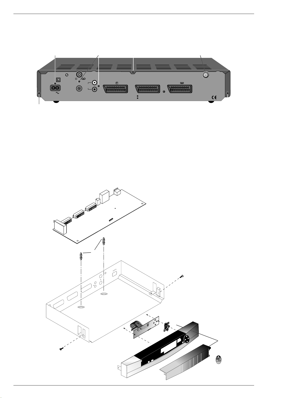
Ausbauhinweise
Gehäuseoberteil
- 3 Schrauben A herausdrehen (Fig. 1).
- Gehäuseoberteil nach hinten abziehen.
CC
CH.ADJ.
MAINS
INPUT
230V
50/60 Hz
13W MAX.
A
Frontblende
- Gehäuseoberteil abnehmen.
- 2 Schrauben B an den Seitenteilen herausdrehen (Fig. 2).
- Frontblende nach vorne abnehmen.
Chassisplatte
- Gerät öffnen.
- Frontblende abnehmen.
- 3 Schrauben C an der Rückseite herausdrehen (Fig. 1).
- Befestigungsmutter F für den SAT-Tuner entfernen.
- 2 Abstandshalter D in der Chassisplatte zusammendrücken (Fig. 2),
Druckplatte nach oben ausrasten und Chassisplatte nach vorne
herausziehen.
TV /VCR
AERIAL
AUDIO
OUT
L
R
TV
Disassembly Instructions
Upper Part of the case
- Undo 3 screws A (Fig. 1).
- Remove the upper part of the case towards the back.
A
DECODER
DO NOT REMOVE COVERS
HAZARD-LIVE PARTS
VCR
Fig. 1
Front Panel
- Remove the upper part of the case.
- Undo 2 screws B one on each side of the case (Fig. 2).
- Remove front panel forwards.
Chassis Board
- Open the receiver.
- Remove the front panel.
- Undo 3 screws C from the rear panel (Fig. 1).
- Remove fastening nut F for the SAT Tuner.
- Release 2 expansion clips D at the main PCB (Fig. 2), lift the main
PCB upwards and forwards.
F
LNC
13V/18V
300mA DC
MADE IN U.K.
A
D
B
B
Fig. 2
1 - 4 GRUNDIG Service
Page 5
STR 6100 Allgemeiner Teil / General Section
GRUNDIG Service 1 - 5
Bedienhinweise Dieses Kapitel enthält Auszüge aus der Bedienungsanleitung. Weitergehende Informationen entnehmen Sie bitte der gerätespezifischen Bedienungsanleitung, deren Materialnummer Sie
in der entsprechenden Ersatzteilliste finden.
❒
Videorecorder
Besitzen Sie einen Videorecorder mit EURO-AVBuchse, so erreichen Sie optimale Aufnahmequalität, wenn Sie den Videorecorder durch ein EUROAV-Kabel (von Ihrem Händler) mit der Buchse VCR
Ihres Receivers verbinden.
w
!
Über die Buchse VCR des Receivers werden keine
Menüeinblendungen ausgegeben. Eine Videoaufzeichnung bleibt somit vom Menüaufruf unbeeinträchtigt.
Bei Wiedergabe einer Videoaufzeichnung werden
die Signale des Videorecorders (Buchse VCR) zum
TV-Gerät (Buchse TV) durchgeschleift (auch in
Bereitschaft).
❒
Decoder
Besitzen Sie einen Decoder mit EURO-AV-Buchse,
so erreichen Sie optimale Qualität, wenn Sie den
Decoder durch ein EURO-AV-Kabel (von Ihrem
Händler) mit der Buchse DEC Ihres Receivers verbinden.
Wenn Sie einen Decoder angeschlossen haben,
kontrollieren Sie bitte die Decodernormauswahl im
Menü “Systemeinstellungen” (»
/
1«) und die
Decodereinstellung jedes betroffenen Programmplatzes im Menü Programmplatzeinstellungen
(»
/
V–A«).
2
1
6
1
Wenn Sie den Receiver ans Netz anschließen,
befindet er sich in Bereitschaft, die rote Anzeige
leuchtet.
Anschluß der Satellitenantenne
w
!
Beachten Sie unbedingt die Sicherheits- und Aufstellhinweise auf Seite 2.
Schließen Sie das Kabel Ihrer Satellitenantenne(n)
an die Eingangsbuchse LNC (Schraubanschluß) an
der Rückseite Ihres Gerätes an.
Kontrollieren Sie, ob die vorprogrammierte LNCOszillatorfrequenz (siehe Seiten 10 und11) mit der
des jeweils verwendeten LNCs übereinstimmt.
Anschluß mit EURO-AV-Kabel
❒
Fernsehgerät
Besitzt Ihr Fernsehgerät einen EURO-AV-Eingang,
so erreichen Sie die beste Bildqualität, wenn Sie mit
einem EURO-AV-Kabel (von Ihrem Händler) die
EURO-AV Buchse Ihres Fernsehgerätes mit der
Buchse TV Ihres Receivers verbinden.
w
!
Nur wenn Sie die Buchse TV des Receivers verwenden, erscheinen bei Menüaufruf Bildschirmeinblendungen auf dem Bildschirm des TV-Gerätes.
1
6
1
6
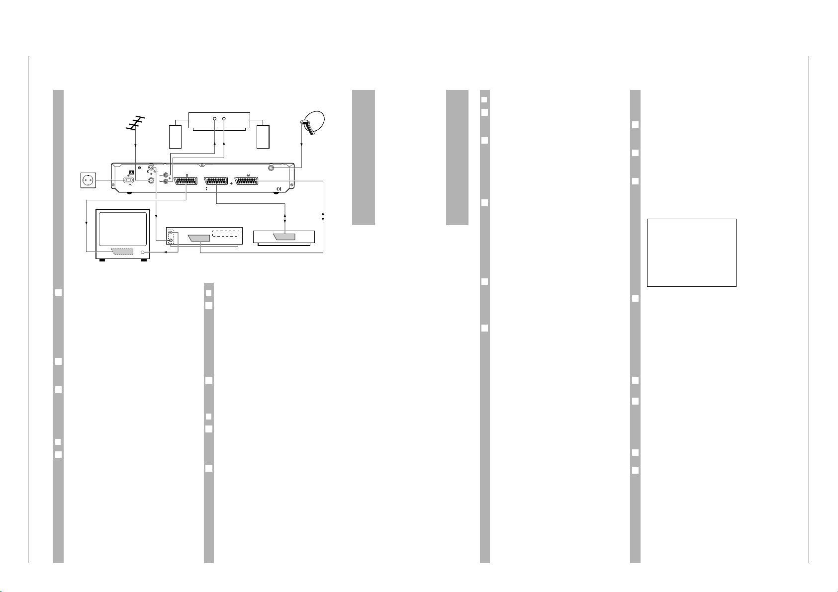
Anschließen
CH.ADJ.
AERIAL
MADE IN U.K.
VCR
DECODER
HAZARD-LIVE PARTS
DO NOT REMOVE COVERS
TV
TV /VCR
R
L
AUDIO
OUT
13W MAX.
50/60 Hz
230V
INPUT
MAINS
300mA DC
13V/18V
LNC
VCR
Decoder
LR
HiFi-Amplifier
t
t
Terrestrische Antenne
Satellitenantenne
HF-Kabel
HF-Kabel
❒
Zweiter Videorecorder oder Decoder
Wollen Sie statt eines Decoders einen zweiten
Videorecorder anschließen nutzen Sie dazu bitte die
Buchse DEC.
Sie können an die Buchse VCR einen zweiten Decoder statt eines Videorecorders anschließen, falls
dieser für die Decodernorm “normal” ausgelegt ist.
Die Decodernormauswahl (siehe Seite 11) ist nur
für die Buchse DEC möglich.
Terrestrischer Empfang
Wollen Sie auch terrestrische Programme empfangen, schließen Sie das Kabel der terrestrischen
Antenne an den Eingang AERIAL an der Rückseite
des Receivers. Videorecorder und TV-Gerät erhalten das Signal über den Modulatorausgang TV/VCR
des Receivers.
Anschluß über den
Modulatorausgang
Besitzt Ihr TV-Gerät oder Ihr Videorecorder keine
EURO-AV-Buchse, erhält dieses Gerät auch die
SAT-Signale über die Buchse TV/VCR. In diesem
Fall müssen Sie die Geräte aufeinander abstimmen.
Der Modulator des Receivers ist werkseitig auf
Kanal 37 eingestellt.
Die Vorgehensweise zum Abstimmen ist im folgender Abschnitt beschrieben.
6
6
6
6
1
Fernsehgerät und Videorecorder
auf den Receiver abstimmen
Diese Einstellung kann entfallen, wenn der Receiver
über ein EURO-AV-Kabel mit dem Fernsehgerät
oder dem Videorecorder verbunden ist.
Drücken Sie an der Fernbedienung des Receivers
nacheinander die Tasten .und 1. Der Receiver
sendet auf Kanal 37 eine Menütafel.
Wählen Sie an Ihrem Fernsehgerät einen freien Programmplatz und stellen den UHF-Kanal 37 (Ausgangskanal des Receivers) gemäß Bedienungsanleitung Ihres Fernsehgerätes ein. Sie sehen dann
folgendes Bild.
Sollte dieser Kanal bereits durch einen Fernsehkanal oder ein anderes Gerät (z.B. Ausgang eines
Videorecorders) belegt sein, sehen Sie Störungen
(wenn das andere Gerät eingeschaltet ist).
Stellen Sie in diesem Fall den Programmplatz Ihres
Fernsehgerätes auf einen freien Kanal im Bereich 28
bis 47 ein.
Drehen Sie mit einem kleinen Schraubendreher die
Einstellschraube »CH. ADJ.« an der Rückseite des
Receivers, bis Sie ein Bild sehen.
Optimieren Sie Bild und Ton über die Feineinstellung Ihres Fernsehgerätes.
Stellen Sie auf die gleiche Weise auch einen freien
Programmplatz Ihres Videorecorders auf den
Receiverausgang ein.
Anschluß einer HiFi-Anlage
Die beste Tonqualität erhalten Sie durch Tonwiedergabe über eine HiFi-Anlage.
Verbinden Sie dazu die Buchsen AUDIO OUT L
(links) und R (rechts) an der Rückseite des Receivers über ein Cinch-Kabel mit Ihrem HiFi-Verstärker.
1
6
5
4
3
&
300
Å●
e
20:14
Å●■ 22:05
Å ✓
´ 16:37
6 / OK
2
1
6
Anschließen
Page 6
Allgemeiner Teil / General Section STR 6100
1 - 6 GRUNDIG Service
22 kHz Umschaltung
Für jeden Programmplatz kann im Menü
“Programmplatzeinstellungen” gewählt werden, ob
das (statische) 22 kHz Signal ausgeschaltet (Einstellung »–«) oder eingeschaltet sein soll (Einstellung »~«).
Das (statische) 22 kHz Signal kann für folgende
Umschaltungen verwendet werden:
Wollen Sie Sender von 2 Satelliten mit 2 Antennen
(siehe Zeichnung) oder mit einer Antenne mit 2
LNCs (ohne Zeichnung) empfangen, so kann mit
dem 22 kHz Signal ein 22 kHz Umschaltrelais
gesteuert werden , um zwischen den 2 LNCs umzuschalten (siehe Abbildung).
Bei einem Universal-LNC schaltet das 22 kHz Signal
zwischen unterem und dem oberem Frequenzbereich eines Satelliten um. Bei Astra wird der obere
Frequenzbereich nur für digitalen Empfang
benötigt.
LNC-Ansteuerung mit DiSEqC
Weiterhin wird die zukunftsorientierte digitale LNCSteuerung mittels sogenanntem DiSEqC-Signal
(Digital Satellite Equipment Control) genutzt. Die
verwendete Antennenanlage muß für den entsprechenden Anwendungsfall und DiSEqC ausgelegt
sein.
Bei der DiSEqC-Steuerung werden in einer
bestimmten Anordnung gepulste 22 kHz Signale
ausgegeben, in denen die gesamte Information für
die LNC-Steuerung enthalten ist.
6
6
2
1
6
6
ToneBurst (Mini-DiSEqC)
Nach dem DiSEqC-Signal wird noch ein sogenanntes ToneBurst Signal (auch Mini-DiSEqC-Signal
genannt) ausgegeben. Dieses beinhaltet die Wahl
des Satelliten (A/B). Sie können somit auch einen
Mini-DiSEqC-Schalter dazu verwenden, um zwischen den zugehörigen LNCs zu schalten.
Ist der obere Frequenzbereich gewählt, wird nach
dem DiSEqC-Signal und dem ToneBurst-Signal
auch das statische 22 kHz Signal ausgegeben.
Somit können Sie den unteren (Einstellung »–«)
und oberen (Einstellung »~«) Frequenzbereich
zweier Satelliten empfangen, wenn Sie zwei Universal LNCs installieren (siehe Abbildung).
Sie können die beiden Signale auch dazu verwenden, um jeweils einen Frequenzbereich von vier
Satelliten zu empfangen.
6
6
6
6
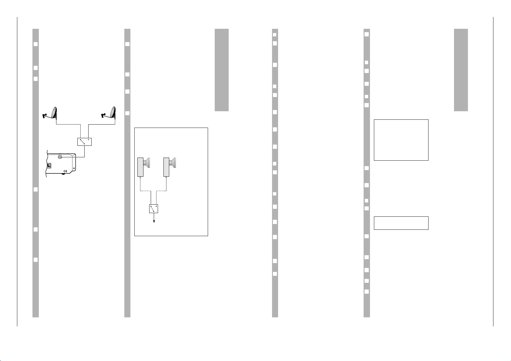
Mehrsatellitenempfang
MADE IN U.K.
R
300mA DC
13V/18V
LNC
22 kHz
Schalter
0 kHz
(Einstellung
z.B. »V–A«)
22 kHz
(Einstellung
z.B. »V~A«)
Beispiel:
Empfang des unteren und oberen
Frequenzbereiches zweier Satelliten
»–«: unterer Frequenzbereich
»~«: oberer Frequenzbereich
Universal LNCs
ToneBurst (Mini-DiSEqC)Schalter (A/B)
STR 6100
A B
Bedienen
❒
Auswahl eines Satellitenprogramms
Sie können die Programmplatznummer mit den Zifferntasten der Fernbedienung direkt eingeben
(mehrstellige Programmplatznummern müssen
innerhalb von 3 Sekunden eingegeben werden).
Mit den Tasten ]|der Fernbedienung oder den
Tasten wqam Receiver können Sie die Programmplätze schrittweise weiterschalten (bei längerem
Drücken: Schnelldurchlauf der Programmplätze).
❒
Bereitschaft (stand by)
Wenn Sie die Taste bder Fernbedienung oder die
Taste 8 am Receiver drücken, schalten Sie den
Receiver in Bereitschaft (stand by).
Mit denselben Tasten können Sie den Receiver aus
der Bereitschaft wieder zum zuletzt gewählten Programmplatz (last station memory) einschalten.
Mit den Tasten ]|der Fernbedienung oder den
Tasten wqam Receiver können Sie den Receiver
auch aus Bereitschaft wieder einschalten.
Mit den Zifferntasten der Fernbedienung können Sie
auch aus Bereitschaft direkt den gewünschten Programmplatz wählen.
❒
Sperren des Receivers
Mit der Receiversperre »
)
…« im Menü “System-
einstellungen” können Sie den gesamten Receiver
sperren (siehe Beschreibung Menüs “Systemeinstellungen” im Kapitel “Einstellungen”).
❒
Bevorzugte Programme
(Favoritenprogramme)
Um auf Ihre Lieblingsprogramme schnell Zugriff zu
haben, können Sie diese als Favoritenprogramme
markieren.
Im Normalbetrieb schalten Sie mit den Tasten
]|
zum nächsthöheren bzw. nächstniedrigeren
Programmplatz.
Im Favoritenbetrieb schalten Sie mit den Tasten
]|
nur zu vorher ausgewählten Satellitenprogrammen, nicht ausgewählte Programme werden
ausgelassen. Vor der Programmplatznummer
erscheint das Symbol »(«.
Drücken Sie die Taste
¢
TXT
k um zwischen Normalbe-
trieb und Favoriten-Betrieb umzuschalten.
Wenn Sie mit den Zifferntasten einen Programmplatz direkt anwählen (selbst wenn dies ein Favoriten-Programmplatz ist) oder in Bereitschaft schalten, ist der Favoriten-Betrieb automatisch ausgeschaltet.
6
1
6
6
6
6
4
3
2
1
2
1
Um ein Programm als Favoritenprogramm zu kennzeichnen, wählen Sie den entsprechenden Programmplatz und rufen das Menü “Programmplatzeinstellungen“ auf. Dort wählen Sie »( ✓«
(siehe Beschreibung des Menüs “Programmplatzeinstellungen“).
❒
Stummschalten (Ton aus)
Drücken Sie die Taste
¢
a
um den Ton aus- bzw.
wieder einzuschalten.
Solange der Ton stummgeschaltet ist, erscheint
rechts oben auf dem Bildschirm das Zeichen a.
❒
Statusanzeige
Mit der Taste .können Sie die Statusanzeige einblenden, nach wenigen Sekunden erlischt die Einblendung von selbst.
Uhrzeit, Programmplatznummer und die für diesen
Programmplatz gewählten Einstellungen werden
angezeigt (Erläuterungen siehe nächstes Kapitel).
Solange die Statusanzeige eingeblendet ist, können
Sie mit den Tasten 1… 3die Menüs aufrufen.
❒
Einstellen der Lautstärke (Volume)
Wenn Sie eine der Tasten xodercdrücken, wird
ein Menü zum Ändern der Lautstärke aufgerufen.
Die Lautstärkeeinstellung wirkt sich nur auf die
EURO-AV-Buchse »TV« aus, hat also keinen Einfluß
auf die EURO-AV-Buchsen für Videorecorder (VCR)
und Decoder (DEC).
Sie können die Lautstärke mit den Tastenxczwischen 0 und 32 einstellen.
Speichern Sie den Wert mit O ab, dann bleibt er
dauerhaft erhalten.
Mit.können Sie die Einstellung rückgängig
machen, wenn Sie noch nicht gespeichert ist.
Wenn Sie weder.noch O drücken, wird das
Menü nach einigen Sekunden verlassen. Der eingestellte Wert bleibt gültig, bis Sie den Receiver in
Bereitschaft schalten, danach wird der vorhergehende Wert wieder angenommen.
6
6
3
2
6
+ 24
6 / OK
1
2
6
&
300
}
11.494 GHZ
$
V–A
+ 7.02 MHZ 7.20 MHZ
~ PANDA
´ 16:35
6 1: ´ 2:
&
3:
}
1
6
1
6
Page 7
STR 6100 Allgemeiner Teil / General Section
GRUNDIG Service 1 - 7
Einstellungen
Die Statusanzeige
Wenn Sie die Taste .der Fernbedienung einmal
drücken, erscheint auf dem Bildschirm des Fernsehgerätes kurzzeitig die Statusanzeige.
Dabei bedeutet:
&
300 Programmplatznummer
}
11.494 GHZ Sendefrequenz des Satelliten
$
V–A LNC-Einstellung: Polarisation
V/H 22 kHz Schaltfrequenz
aus (–)/ein (~) Satellitenwahl A/B
+ 7.02 MHZ 7.20 MHZ linke und rechte Tonfrequenz
~
PANDA Deemphase/Rauschunter-
drückung
´ 16:35 Uhrzeit
6 1: ´ 2:
&
3: } Tastenfunktionen:
6: Statusanzeige sofort
beenden,
1:
´ Timermenü öffnen
2:
&
Menü “Programmplatzeinstellungen”
öffnen
3:
}
Menü “Systemeinstellungen” öffnen
Die Uhrzeit kann im Timermenü eingestellt werden.
Die anderen Einstellungen (Sendefrequenz, LNCEinstellung, Toneinstellungen) erfolgen im Menü
“Programmplatzeinstellungen”.
Funktionsweise der Menüs
Rufen Sie die Statusübersicht mit der Taste .auf.
Solange die Statusanzeige zu sehen ist, können Sie
mit den Ziffertasten 1…3die drei Menütafeln aufrufen.
Bei aktiver Menütafel gelten grundsätzlich folgende
Tastenfunktionen (diese werden bei der Menübeschreibung nicht immer wiederholt).
Wenn Sie das TV-Bild im Hintergrund stört, können
Sie mit der Taste
¢
TXT
k einen blauen Bildhintergrund
einblenden. Bei erneutem Drücken der Taste
¢
TXT
k
erscheint wieder das TV-Bild im Hintergrund.
Innerhalb eines Menüs können Sie mit den Tasten
]|
die einzelnen Zeilen oder Werte anwählen.
3
2
6
1
6
&
300
}
11.494 GHZ
$
V–A
+ 7.02 MHZ 7.20 MHZ
~ PANDA
´ 16:35
6 1: ´ 2:
&
3:
}
1
Der Wert, den Sie ändern können, blinkt in der Bildschirmdarstellung (CURSOR). Sie können diesen
Wert mit den Tasten xcändern. Bei Zahlenwerten erfolgt meist eine schnelle Wertänderung durch
längeres Drücken der Tasten xc, oft ist eine
direkte Zifferneingabe möglich.
Um die geänderten Einstellungen zu speichern,
drücken Sie die Taste O. Die Menütafel wird automatisch geschlossen. Kurzzeitig erscheint die Statusanzeige.
Um ein Menü zu verlassen ohne zu speichern,
drücken Sie die Taste .. Die geänderten Einstellungen werden dabei rückgängig gemacht. Kurzzeitig erscheint die Statusanzeige.
Das Menü Systemeinstellungen
❒
Übersicht
Drücken Sie nacheinander die Tasten .und 3.
Nacheinander erscheint die Statusanzeige und das
Menü zu Systemeinstellungen.
Dabei bedeutet:
$
–A 09.750 LO-Frequenz des LNCs ohne 22 kHz
Schaltsignal, Satellitenwahl A
$
~A 09.750 LO-Frequenz des LNCs mit 22 kHz
Schaltsignal, Satellitenwahl A
$
–B 09.750 LO-Frequenz des LNCs ohne 22 kHz
Schaltsignal, Satellitenwahl B
$
~B 09.750 LO-Frequenz des LNCs mit 22 kHz
Schaltsignal, Satellitenwahl B
$
%
✓ LNC-Spannungsversorgung ein/aus
W144 Voreinstellung Kontraststufe 1
W230 Voreinstellung Kontraststufe 2
/
1 Decodernormauswahl
)
X Receiver gesperrt ja/nein
6 / OK6: Menü verlassen,
OK: Speichern und Menü verlassen
6
$
–A 09.750 GHZ
$
~A 09.750 GHZ
$
–B 09.750 GHZ
$
~B 09.750 GHZ
$
%
✓
W144
W230
/
1
)
X
6 / OK
1
6
5
4
Einstellungen
❒
LNC-Oszillatorfrequenzen ($)
Der Receiver ist für folgende LNB Oszillatorfrequenzen vorprogrammiert:
Auswahl A, 22 KHz aus: 9750 MHz
Auswahl A, 22 KHz ein: 9750 MHz
Auswahl B, 22 KHz aus: 9750 MHz
Auswahl B, 22 KHz ein: 9750 MHz
Falls Sie ein LNC mit einer anderen Oszillatorfrequenz verwenden, können Sie die jeweilige Oszillatorfrequenzeinstellung ändern.
Mit den Tasten xcändern Sie den Wert schrittweise, mit Zifferntasten können Sie ihn direkt eingeben.
Wenn Sie mehrere LNCs verwenden, sind alle Oszillatorfrequenzen zu kontrollieren und – falls nötig –
neu einzugeben.
❒
LNC-Spannungsversorgung ein-/
ausschalten ($%)
Bei der werkseitigen Voreinstellung versorgt der
Receiver die Satellitenantenne mit Strom.
Ist Ihr Empfänger mit anderen Receivern an eine
Gemeinschaftsantenne angeschlossen (Einkabellösung), schalten Sie die LNC-Spannungsversorgung
aus (»
$
%
X«), sonst lassen Sie die Einstellung
»
$
%
✓«.
❒
Voreinstellung der Kontraststufen 1 und 2
(
W1, W 2)
Im Menü “Programmplatzeinstellungen“ können
Sie für jeden Programmplatz eine der beiden Kontraststufen wählen.
w
!
Die voreingestellten Werte sollten Sie möglichst
nicht ändern, da sich sonst der Kontrast aller Programmplätze mit dieser Kontrasteinstellung ebenfalls ändert.
In Ausnahmefällen können Sie die Werte der Kontraststufen mit den Tasten xcändern.
❒
Decodernormauswahl (/)
Sie können zwischen den folgenden 4 Decodereinstellungen wählen:
1 normal
2 PAL
3 Basisband
4 MAC (für D2MAC Decoder)
Nähere Informationen finden Sie in der Bedienungsanleitung Ihres Decoders.
6
1
1
6
1
6
2
1
6
❒
Receiver sperren ())
Sie können den Receiver sperren.
Receiver nicht gesperrt: ») X«
Receiver gesperrt: ») ✓«
Wenn Sie den Receiver sperren und danach in
Bereitschaft schalten, läßt er sich nur dann wieder
einschalten, wenn Sie die richtige Tastenkombination eingeben.
Alle Programmplätze und alle Menüs sind gesperrt.
Bei gesperrtem Receiver
Wenn Sie den Receiver sperren, erscheint jedesmal
beim Einschalten aus Bereitschaft:
») . . . .«
Jeder Punkt steht für eine Taste. Nach jedem
Tastendruck wird ein Punkt durch einen kleinen
Strich ersetzt.
Drücken Sie nacheinander die folgenden Tasten der
Fernbedienung
cx
|]
.
w
!
Dieser “Code” läßt sich nicht ändern. Merken Sie
ihn sich deshalb gut und halten Sie ihn geheim.
Nach der Eingabe des richtigen Codes steht der
Receiver frei zur Verfügung. Wenn Sie den Receiver
wieder in Bereitschaft schalten, ist er erneut
gesperrt.
Bei eingeschaltetem Receiver kann die Sperre im
Menü jederzeit wieder aufgehoben werden.
Das Menü Programmplatzeinstellungen
Das Gerät ist bereits auf die aktuellen Programme
vieler Satelliten vorprogrammiert, eine Korrektur ist
in den meisten Fällen nicht nötig.
Es kommen aber immer wieder neue Programme
hinzu oder Sendefrequenzen werden geändert.
Einen aktuellen Stand der Sendefrequenzen können
Sie über Videotexttafel verschiedener Sender abfragen (z.B. SAT 1: Videotexttafel 675) bzw. einschlägigen Fachzeitschriften entnehmen. Sie können
diese Sender im Video-Menü nachprogrammieren.
Im Menü “Programmplatzeinstellungen“ haben Sie
Zugriff auf die Bild- und Toneinstellungen der einzelnen Programmplätze.
Wählen Sie mit den Zifferntasten oder den Tasten
]|
den Programmplatz, dessen Einstellungen
Sie kontrollieren oder verändern möchten.
w
!
Sie können den Programmplatz nicht innerhalb des
Menüs mit der Programmnummer wählen.
1
6
6
6
6
6
3
2
1
6
1
Page 8
Allgemeiner Teil / General Section STR 6100
1 - 8 GRUNDIG Service
Einstellungen
❒
Übersicht
Drücken Sie nacheinander die Tasten .und 2.
Nacheinander erscheint die Statusanzeige und das
Menü für die Programmplatzeinstellungen.
Dabei bedeutet:
&
300 Programmplatznummer
}
11.494 GHZ Sendefrequenz des
Satelliten
$
V~B Wahl der Polarisation,
22 kHz Signal ein/aus,
Satellitenwahl A/B
+ 7.02 MHZ 7.02 MHZ linke und rechte
Tonfrequenz
~
PANDA Deemphase /Rauschunter-
drückung
(
✓ in der Favorittabelle
aufgenommen
W 1 Kontrasteinstellung
/
X–X Decodereinstellung
=
+ Bild normal/invers
6 / OK 6: Menü verlassen,
OK: Speichern und Menü
verlassen
❒
Programmplatznummer (&)
Die Programmplatznummer wird zur Kontrolle
angezeigt. Sie kann im Menü nicht geändert
werden.
❒
Sendefrequenz des Satelliten (})
Sie können die Sendefrequenz des Satelliten mit
den Zifferntasten direkt eingeben oder den eingestellten Wert mit den Tasten xcin 1-MHzSchritten ändern.
❒
Polarisation und Schaltsignal ($)
Hier können Sie wählen, ob Sie ein horizontal (H)
oder ein vertikal (V) polarisiertes Signal empfangen
wollen (bei V wird zum LNC eine 14 V Gleichspannung ausgegeben, bei H 18 V).
Bei Empfang mit mehreren Satellitenantennen,
LNCs oder einem LNC mit Bereichsumschaltung,
können Sie durch Ein- bzw. Ausschalten des 22 kHz
Signals und der Satellitenwahl A/B die Signalquelle
wählen (siehe Kapitel “Mehrsatellitenempfang”)
&
300
}
11.494 GHZ
$
V–A
+ 7.02 MHZ 7.02 MHZ
~
PANDA
(
✓
W 1
/
X–X
=
+
6 / OK
1
❒
Toneinstellungen (+)
Wählen Sie mit den Tasten xcdie gewünschte
Toneinstellung (Trägerfrequenz des linken und des
rechten Tonkanals).
Die 16 Toneinstellungen (3 Stereo, 13 Mono) sind
werkseitig vorprogrammiert (sie können nicht
geändert werden).
❒
Deemphasis Rauschunterdrückung (
~
)
Sie können zwischen PANDA, 50µs (50US), und
J17 wählen, entscheiden Sie nach bestem Klangeindruck.
❒
Favoritenprogramm (()
Um auf Ihre Lieblingsprogramme schnell Zugriff zu
haben, können Sie diese als Favoritenprogramme
markieren (»( ✓«).
Wenn keine Menütafel angezeigt wird, können Sie
mit der Taste
¢
TXT
k zwischen normalem Betrieb und
Favoritenbetrieb umschalten. Im Favoritenbetrieb
stehen beim Umschalten mit den Tasten ]|nur
die markierten Favoritenprogramme zur Verfügung.
Vor der Programmplatznummer erscheint das Symbol » ( «.
Wenn Sie eine Programmplatznummer über die Zifferntasten direkt eingeben, wird der Favoritenbetrieb automatisch ausgeschaltet.
Beim Einschalten des Gerätes aus Bereitschaft
(stand by) ist der Favoritenbetrieb ausgeschaltet.
❒
Kontrast/Videohub (W)
Die Satelliten senden mit unterschiedlichem Videohub. Dies bedingt eine entsprechende Kontrasteinstellung am Receiver.
Die richtigen Kontraststufe ist werkseitig schon
gewählt.
Bei Bedarf oder Neuprogrammierung können Sie
zwischen 2 werkseitig vorprogrammierten Kontraststufen wählen (1 und 2).
Diesen vorgewählten Wert sollten Sie nicht ändern,
da sich sonst der Kontrast aller Programmplätze
mit dieser Kontrasteinstellung ebenfalls ändert.
In Ausnahmefällen können Sie im Menü Systemeinstellungen die Werte der Kontraststufen ändern
(siehe Abschnitt “Voreinstellung der Kontraststufen
1 und 2“ auf Seite 11).
6
6
2
1
1
6
1
Einstellungen
❒
Uhrzeit (´; z.B. Sommer-/Winterzeit)
Bei Verwendung der Timerfunktion (Timer-Menü)
muß die Uhrzeit korrekt eingegeben sein. Bitte kontrollieren Sie deshalb die eingestellte Uhrzeit.
w
!
Bei Stromausfall ist die Uhr unterbrochen und wird
deshalb automatisch gelöscht.
Mit den Tasten ]|können Sie zwischen Stunden- (0…23) und Minuteneingabe (0…59) wechseln.
Mit den Tasten xcändern Sie den angewählten
Wert.
❒
Programmplatz wählen (&)
Automatisch ist die Nummer des Programmplatzes
vorgewählt, das Sie gerade eingestellt haben.
Wählen Sie mit den Zifferntasten oder den Tasten
xc
die gewünschte Programmplatznummer.
❒
Start- und Stoppzeit eingeben
(
Å●
e
, Å●■)
Mit den Tasten ]|können Sie zwischen der
Start- und der Stoppzeit und zwischen der Stunden(0…23) und Minuteneingabe (0…59) wechseln.
Geben Sie den Wert mit den Zifferntasten ein, oder
ändern Sie ihn mit den Tasten xc.
Ist eine frühere Stoppzeit eingestellt als die Startzeit, bleibt der Timer bis zum Erreichen der Stoppzeit am nächsten Tag aktiv.
❒
Timer speichern oder löschen (Å)
Schalten Sie mit den Tasten xcden Timer ein
(Stellung » ✓«).
Speichern Sie die Einstellungen mit O, das Timermenü wird damit automatisch verlassen.
Wollen Sie das Timermenü verlassen ohne zu speichern, drücken Sie die Taste ..
Schalten Sie den Receiver auf Bereitschaft, wenn
Sie ihn derzeit sonst nicht benötigen.
w
!
Der Timer muß sich zur Startzeit des Timers in
Bereitschaft befinden.
Zum Zeichen, daß der Timer programmiert ist,
leuchtet außer der roten auch die grüne Anzeige
Wollen Sie eine bestehende Timerprogrammierung
ändern, rufen Sie das Timer Menü erneut auf.
Sie können die aktuelle Einstellung durch Eingabe
neuer Werte überschreiben oder löschen, indem Sie
das Timermenü mit der Einstellung » Å X«
verlassen.
6
4
6
3
6
2
1
6
2
1
1
6
2
1
6
❒
Decodereinstellung (/)
Je nach Decoder können Sie für jeden Programmplatz eine der vier möglichen Einstellungen wählen:
X–X Decoder aus
–X Nur das Tonsignal wird decodiert
X–=Nur das Bildsignal wird decodiert
–=Bild und Tonsignal werden decodiert
❒
Videopolarität (=)
Sie können positive (»+«) oder negative (»–«)
Videopolarität einstellen.
Die Einstellung »+« ist vorprogrammiert. Für manche Decoder benötigen Sie die Einstellung »–«.
Das Timer Menü/
Videoaufzeichnungen
Das Menü Timer stellt einen 24-Stunden-Timer für
Videoaufzeichnungen zur Verfügung.
Bei aktivem Timer ist es nicht möglich, den Programmplatz umzuschalten oder Menütafeln einzublenden. Bei einer Videoaufzeichnung sollte deshalb
immer der Timer des Receivers programmiert werden (siehe auch Abschnitt “Während einer Timeraufnahme”).
❒
Übersicht
Drücken Sie nacheinander die Tasten .und 1.
Nacheinander erscheint die Statusanzeige und das
Timer Menü.
Kontrollieren Sie die Uhrzeit und korrigieren Sie
diese, falls nötig.
Dabei bedeutet:
&
300 Programmplatznummer
Å●
e
20:14 Startzeit
Å●■ 22:05 Stoppzeit
Å ✓ Timer ein/aus
´ 16:37 Uhrzeit
6
/
OK
6: Menü verlassen ohne zu speichern,
OK: Speichern und Menü verlassen
&
300
Å●
e
20:14
Å●■ 22:05
Å ✓
´ 16:37
6
2
1
6
6
6
Page 9

STR 6100 Allgemeiner Teil / General Section
GRUNDIG Service 1 - 9
Operating Hints This chapter contains excerpts from the operating instructions. For further particulars please refer to the appropriate user instructions the part number of which is indicated in the relevant
spare parts list.
❒
Video recorder
If your video recorder is provided with a EURO-AV
socket (”Euroconnector”), you get the best picture
quality if you connect this socket via a EURO-AV
cable (available from your dealer) to the VCR socket
of your receiver.
w
!
No on-screen displays are output via the VCR
socket of the receiver. That is why video recordings
cannot be affected by calling up menus.
When playing back video recordings, the signals
from the video recorder (VCR socket) are looped
through the satellite receiver (also in stand-by) to
the TV set (TV socket).
❒
Decoder
If you use a decoder which is provided with a
EURO-AV socket (”Euroconnector”), you get the
best picture quality if you connect this socket via a
EURO-AV cable (available from your dealer) to the
DEC socket of your receiver.
After connecting the decoder, please check the
decoder mode selected in the "System setup" menu
("
/
1 ") and the decoder setting of
every programme position concerned
("
/
V–
A
").
2
1
6
1
After connecting the receiver to the mains supply it
is in stand-by. The red indicator is lit.
How to connect the satellite aerial
w
!
It is absolutely necessary to respect the safety and
installation notes on page 2.
Connect the cable of your satellite aerial(s) to the
LNC input(s) (screw terminal) on the back of your
receiver.
Check to see whether the preset LNC oscillator
frequency (see pages 10 and 11) corresponds to
the LNC used.
Connection via a EURO-AV cable
❒
TV set
If your TV receiver is provided with a EURO-AV
input (”Euroconnector”), you get the best picture
quality if you connect this socket via a EURO-AV
cable (available from your dealer) with the TV
socket of your receiver.
w
!
Only when using the TV socket of the receiver, the
on-screen displays (menus) will appear when they
are called up.
1
6
1
6
Connection
CH.ADJ.
AERIAL
MADE IN U.K.
VCR
DECODER
HAZARD-LIVE PARTS
DO NOT REMOVE COVERS
TV
TV /VCR
R
L
AUDIO
OUT
13W MAX.
50/60 Hz
230V
INPUT
MAINS
300mA DC
13V/18V
LNC
VCR
Decoder
LR
HiFi-Amplifier
t
t
Terrestrial aerial
Satellite aerial
RF cable
RF cable
❒
Second video recorder or decoder
If you wish to connect a second video recorder
instead of the decoder, use the DEC socket for this.
You can connect a second decoder instead of the
video recorder to the VCR socket, provided the
decoder is suited for the “normal“ decoder mode.
The decoder mode selection (see page 11) is only
possible for the DEC socket.
Terrestrial reception
If you wish to receive also terresrtrial programmes,
connect the terrestrial aerial cable to the AERIAL
socket on the rear of the receiver. The signal for the
video recorder and the TV set is available at the
TV/VCR modulator output of the receiver.
Connection via the
modulator output
If your TV set or video recorder is not provided with
a EURO-AV socket, these sets are supplied via the
TV/VCR socket with the SAT signals. In this case, it
will be necessary to adjust the sets to each other. At
the factory, the modulator of the satellite receiver
has been preset to channel 37.
The following section describes how the TV set and
video recorder are tuned to the receiver.
Tuning the TV set and video
recorder to the receiver
This adjustment can be omitted if you have connected the receiver via a EURO-AV connecting lead
to the television receiver or video recorder.
Press the
.
key and then the 1key on
the remote control unit of the receiver. The receiver
then will send an on-screen display on channel 37.
Select a free channel position on your TV set and
tune to UHF channel 37 (the receiver's output channel). For this, refer to the instruction book of your TV
set. You will see the following on-screen display.
If this channel is already being used by a TV channel or a different unit (say, your video recorder),
you will see interference if the other equipment is
operating.
3
&
300
Å●
e
20:14
Å●■ 22:05
Å ✓
´ 16:37
6 / OK
2
1
6
6
6
6
6
1
Retune your TV to an unused part of its range
(channel number 28 to 47).
Turn the adjusting screw "CH. ADJ." on the back of
the receiver by means of a small screwdriver until
you see a picture.
Optimize the picture quality by finetuning your TV
set.
Tune in the same way a free programme position of
the video recorder to the receiver's ouptut channel.
How to connect your hifi system
Best sound quality is obtained when connecting the
receiver to hifi equipment.
Connect the AUDIO OUT L (left) and R (right)
sockets on the back of your receiver via a phono
(Cinch) cable (available from your dealer) to the hifi
amplifier.
1
6
5
4
Connection
Additional Information for Units sold in
Great Britain
Units sold in GB are suitable for operation from a 240 V AC,
50 Hz mains supply.
In case this appliance is supplied with a Safet
y Standard
Approved mains lead fitted with a non-rewireable 13 Amp mains
plug which, if unsuitable for your socket, should be cut off and
an appropriate plug fitted by a qualified electrician. The fuse and
fuse holder must be removed from the plug as accidental
insertion of the redundant plug into a 13 Amp socket is likely to
cause an electrical hazard.
Note: The severed plug must be destroyed to avoid a possible
shock hazard should it be inserted into a 13 Amp socket
elsewhere.
If it is necessary to change the fuse in the non-rewireable plug,
the correct type and rating (5 Amp ASTA or BSI approved
BS 1362) must be used and the fuse cover must be refitted. If
the fuse cover is lost or damaged the lead and plug must not be
used until a replacement is obtained. Replacement fuse covers
should be obtained from your dealer.
If a non-rewireable plug or a rewireable 13 Amp (BS 1363) plug
is used, it must be fitted with a 5 Amp ASTA or BSI approved
BS 1362 fuse. If any other type of plug is used it must be protected
by a 5 Amp fuse either in the plug or at the distribution board.
Important:
The wires in the mains lead are coloured in accordance with the
following code:
BLUE – NEUTRAL
BROWN – LIVE
As the colours of the wires in the mains lead of your appliance
may not correspond with the coloured marking identifying the
terminals in your plug, proceed as follows:
Connect the BLUE coloured wire to plug terminal marked with
the letter "N" or coloured black.
Connect the BROWN coloured wire to the plug terminal marked
with a letter "L" or coloured red.
In no circumstance must any of the wires be connected to the
terminal marked with a letter "E", earth symbol , coloured
green or green and yellow.
Replacement mains lead can be obtained from your dealer.
Page 10

Allgemeiner Teil / General Section STR 6100
1 - 10 GRUNDIG Service
22 kHz switch-over
If is possible to select for every programme position in the "Programme position setup" menu
whether the (static) 22 kHz signal is to be de-activated (option "–") or activated (option "~").
The (static) 22 kHz signal can be used for the following switching functions:
If you wish to receive the channels from 2 satellites
with 2 aerials (see figure) or with one aerial having
two LNC's (no figure), the 22 kHz signal can be
used for the control of a 22 kHz relay which then
switches between the two LNC's (see figure).
With a universal LNC, the 22 kHz signal switches
between the high and low frequency range of one
satellite. For the Astra satellite, the high frequency
range is only used for digital reception.
LNC control with DiSEqC
In addition, the future-oriented digital LNC control
by means of the so-called DiSEqC signall (Digital
Satellite Equipment Control) is used. In this case,
the connected aerial system must be able to process the DiSEqC signal and be suited for the special
application.
With the DiSEqC control, 22 kHz signals with a certain pulse sequence are output which contain the
entire information required for the LNC control.
6
6
2
1
6
6
ToneBurst (Mini-DiSEqC)
Following the DiSEqC signal, a so-called ToneBurst
(also called Mini-DiSEqC signal) is output. This signal contains the satellite selection parameter (A/B).
It is therefore also possible to use a ToneBurst
switch to switch over between the assigned LNC's.
If the high frequency range is selected, the static
22 kHz signal will be output in addition to the
DiSEqC signal and the ToneBurst signal.
This allows for the reception of the high (option "~")
and low (option "–") frequency range of two satellites when installing two universal LNCs (see
figure).
The two signals can also be used for the reception
of one frequency range of each of four satellites.
6
6
6
6
Multi-Satellite Reception
MADE IN U.K.
R
300mA DC
13V/18V
LNC
22 kHz
switch
0 kHz
(for example
"V–A" setting)
22 kHz
(for example
"V~A" setting)
Example:
Reception of the high and low
frequency range of two satellites
"–": low frequency range
"~": high frequency range
Universal LNCs
ToneBurst (Mini-DiSEqC)
switch (A/B)
STR 6100
A B
Using the Receiver
❒
Selecting a satellite channel
Use the numeric keys on the remote control unit if
you wish to directly enter the number of the desired
programme position (multi-digit numbers must be
entered within 3 seconds).
Use the ]| keys on the remote control unit or
the wq keys on the receiver to step through the
programme positions (when pressing and holding
down a key, the programme positions scroll at high
speed).
❒
Stand-by
Use the bkey on the remote control unit or the 8
key on the front panel of the receiver to switch the
receiver to stand-by.
Use the same keys to switch the receiver on from
stand-by with the last selected programme position
(last station memory).
Use the ]|keys on the remote control unit or
the wq keys on the receiver to switch the receiver
on again from stand-by.
Using the remote control unit's numeric keypad,
you can also directly select the desired programme
position from stand-by.
❒
Locking the receiver
With the receiver lock option "
)
…" in the "System
setup" menu, you can lock all receiver functions
(see description of the "System setup" menus in the
"Settings" chapter).
❒
Favourite programmes
To have a fast access to your favourite programmes, you can mark these programmes.
In normal mode, the ]| keys switch to the next
higher or next lower programme position.
In favourite mode, the ]| keys will only switch
to programme positions which have been marked
before as favourite programmes. Not marked programme positions are skipped. The symbol "("
appears in front of the programme position
number.
Press the
¢
TXT
k key to toggle between normal and
favourite mode.
If you use the numeric keys to directly select a programme position (also a favourite programme position), or if you switch to stand-by, the favourite
mode is automatically de-activated.
6
1
6
6
6
6
4
3
2
1
2
1
To mark a programme as favourite programme,
select the corresponding programme position and
call up the "Programme position setup" menu. Then
select the "( ✓" option in the menu
(see description of the "Programme position setup"
menu).
❒
Sound mute
Press the
¢
a
key to mute and restore the sound.
As long as the sound is muted, the a symbol is displayed in the top right corner of the picture screen.
❒
Status display
Press the .key to switch on the status display.
After a few seconds, the status display disappears
automatically.
The display shows the time, the programme position number and the settings made for this programme position (for an explanation, see next
chapter).
As long as the status display is on, you can use the
1… 3
keys to call up the menus.
❒
Volume Control
Pressing one of the xcbuttons displays the volume control menu.
The volume control is only effective on the “TV”
EURO-AV socket. It has no effect on the video
recorder (VCR) and decoder (DEC) EURO-AV
sockets.
With the xcbuttons, you can adjust a volume
value between 0 and 32.
Press the O button to store the volume setting in
memory.
As long as the setting is not yet stored in memory,
pressing the .button will restore the old setting.
If neither the .nor the O button is pressed, the
menu is exited after a few seconds. The set value
remains valid until the receiver is switched to
standby. Then the old setting is recovered.
6
6
3
2
6
+ 24
6 / OK
1
2
6
&
300
}
11.494 GHZ
$
V–A
+ 7.02 MHZ 7.20 MHZ
~ PANDA
´ 16:35
6 1: ´ 2:
&
3:
}
1
6
1
6
Page 11

STR 6100 Allgemeiner Teil / General Section
GRUNDIG Service 1 - 11
Settings
The status display
If you press the .key on the remote control unit
once, the status menu is briefly displayed on the
picture screen.
Meaning of symbols:
&
300 Programme position
number
}
11.494 GHZ Satellite channel transmis-
sion frequency
$
V–A LNC setting: polarization V/H,
22 kHz switching frequency
off (–)/on (~),
satellite selection A/B
+ 7.02 MHZ 7.20 MHZ Left and right audio
frequency
~
PANDA Deemphasis/noise
suppression
´ 16:35 Time
6 1: ´ 2:
&
3: } Key functions:
6: cancel status display
instantly,
1:
´ open Timer menu,
2:
&
open "Programme
position setup" menu,
3:
}
open "System setup"
menu.
The time can be set in the Timer menu. The remaining settings (transmission frequency, LNC setup,
audio settings) are made in the "Programme position setup" menu.
The on-screen menu guide
Call up the status menu by pressing the .key. As
long as this menu is displayed, you can call up the
remaining three menus by means of the numeric
keys 1…3.
For a displayed menu, the following key functions
apply principally (these functions will not be
explained again in the menu descriptions).
If you do not wish the TV picture as background,
you can display a blue background by pressing the
¢
TXT
k key. Pressing the
¢
TXT
k key again restores the
TV picture as background.
When in a menu, use the ]|keys to select
menu options or values.
3
2
6
1
6
&
300
}
11.494 GHZ
$
V–A
+ 7.02 MHZ 7.20 MHZ
~ PANDA
´ 16:35
6 1: ´ 2:
&
3:
}
1
A value which can be changed is flashing in the
menu (CURSOR). Change a value with the
xc
keys. Numeric values can be changed at fast speed
by pressing and holding down the xckeys.
In most cases, a direct entry of the value is also
possible.
Press the O key to save the changes made. This
automatically closes the corresponding menu and
briefly displays the status menu.
To exit a menu without saving, press the .key.
The changes made are undone and the status menu
is briefly displayed.
The system setup menu
❒
Overview
Press the .key and then the 3key.
On the picture screen appear the status menu and
then the system setup menu.
Meaning of symbols:
$
–A 09.750 LO frequency of LNC without 22 kHz
switching signal, satellite selection A.
$
~A 09.750 L O frequency of LNC with 22 kHz
switching signal, satellite selection A.
$
–B 09.750 L O frequency of LNC without 22 kHz
switching signal, satellite selection B
$
~B 09.750 L O frequency of LNC with 22 kHz
switching signal, satellite selection B
$
%
✓ LNC voltage supply on/off.
W144 Contrast level 1 preset.
W230 Contrast level 2 preset.
/
1 Decoder mode selection
)
X Receiver lock yes/no.
6 / OK6: exit menu,
OK: save and exit menu.
6
$
–A 09.750 GHZ
$
~A 09.750 GHZ
$
–B 09.750 GHZ
$
~B 09.750 GHZ
$
%
✓
W144
W230
/
1
)
X
6 / OK
1
6
5
4
Settings
❒
LNC oscillator frequencies ($)
The receiver is preprogrammed for the following
LNC oscillator frequencies:
Selection A, 22 KHz off: 9750 MHz
Selection A, 22 KHz on: 9750 MHz
Selection B, 22 KHz off: 9750 MHz
Selection B, 22 KHz on: 9750 MHz
If you should use an LNC having a different oscillator frequency, you can change the corresponding
setting.
Use the xckeys to change the value step by
step, or the numeric keys to enter the value directly.
If you use several LNC's, you must check all oscillator frequencies and correct them if necessary.
❒
LNC voltage supply on/off ($%)
With the default setting made at the factory, the
receiver provides for the voltage supply of the satellite aerial.
If your receiver is connected along with other
receivers to a communal aerial system (single cable
installation), switch the LNC voltage supply off
("
$
%
X"), if not, leave the "
$
%
✓" setting.
❒
Contrast levels 1 and 2 presettings
(
W1, W 2)
You can select one of the two contrast levels in the
"Programme position setup" menu.
w
!
If possible,
the preset
values
should not
be
changed, as
this would
also change
the contrast
setting of all
other programme
positions.
In exceptional cases, you can change the contrast
level by means of the xckeys.
❒
Decoder mode selection (/)
You have the choice between the following decoder
modes:
1 Normal
2 PAL
3 Baseband
4 MAC (for D2MAC decoder)
For detailed information, see the operating instructions of the decoder.
6
1
1
6
1
6
2
1
6
❒
Receiver lock ())
You can lock your receiver.
Receiver not locked: ") X"
Receiver locked: ") ✓"
If you lock your receiver and then switch it to stand-
by, it can be switched on again only by entering the
correct key combination.
All programme positions and all menus are locked.
When the receiver is locked
If you lock your receiver and then switch it on from
standby, the following display appears:
") . . . ."
Each dot stands for a key. When pressing a key, the
corresponding dot is replaced by a small line.
Press the
cx
|]
keys on the remote control
unit one after the other.
w
!
This code
cannot be
changed.
Note it down
and keep it
in a safe
place.
After entering the correct code, the receiver can be
used again. Switching the receiver to stand-by will
lock it again.
When the receiver is switched on, the lock may be
cancelled at any time in the menu.
The programme position setup
menu
The receiver is already preprogrammed for the current channels of many satellites. In most cases, a
correction is not required.
However, new programmes are continuously added
or transmission frequencies are changed. The
current state of the transmission frequencies can be
called up by means of the Teletext pages of various
stations (e.g. Sky News: Teletext page 675), or
the information required can be found in TV programme guides. Changed programmes then can be
re-programmed in the programme position setup
menu.
In the "Programme position setup" menu, you have
access to the picture and sound settings of the individual programme positions.
Use the numeric keys or the ]|keys to select
the programme position for which you wish to
check or change the settings.
w
!
It is not possible to sel-
1
6
6
6
6
6
3
2
1
6
1
Page 12

Allgemeiner Teil / General Section STR 6100
1 - 12 GRUNDIG Service
Settings
❒
Overview
Press the .key and then the 2key.
On the picture screen appear the status menu and
then the programme position setup menu.
Meaning of symbols:
&
300 Programme position
number.
}
11.494 GHZ Satellite channel transmis-
sion frequency.
$
V~B Selection of polarization,
22 kHz signal on/off,
satellite selection A/B.
+ 7.02 MHZ 7.02 MHZ Left and right sound carrier
~
PANDA Deemphasis /noise
suppression.
(
✓ Favourite programme
W 1 Contrast setting
/
X–X Decoder setting
=
+ Normal/inverse picture
6 / OK 6: exit menu,
OK: save and exit menu.
❒
Programme position number (&)
The programme position number is displayed for
checking. It cannot be changed in the menu.
❒
Satellite channel transmission
frequency (
}
)
You can directly enter the satellite channel transmission frequency with the numeric keys or change
the value in 1 MHz steps with the xckeys.
❒
Polarization and switching signal ($)
You can select whether you wish to receive a horizontally (H) or vertically (V) polarized signal (with
V, at 14 V, and with H, at 18 V direct voltage is
applied at the LNC).
When receiving with several satellite aerials or
LNC's, or for LNC range switch-over, you can
select the signal source by switching on and off the
22 kHz signal and by using the A/B satellite select
function (see chapter "Multi-Satellite Reception").
&
300
}
11.494 GHZ
$
V–A
+ 7.02 MHZ 7.02 MHZ
~
PANDA
(
✓
W 1
/
X–X
=
+
6 / OK
1
❒
Sound carriers (+)
Use the xckeys to select the desired frequency
of the sound carriers for the left and right channel.
16 sound carriers (3 stereo, 13 mono) are preset at
the factory (they cannot be changed).
❒
Deemphasis/noise suppression (
~
)
You have the choice between PANDA, 50µs (50US),
and J17. Select the option giving the best sound
quality.
❒
Favourite programme (()
To quickly access your favourite programmes,
these can be marked ("( ✓").
If no menu is displayed, you can use the
¢
TXT
k key
to toggle between normal and favourite mode. In
favourite mode, only the favourite programmes are
availalbe for being selected with the ]|keys.
The symbol " ( " appears in front of the programme
position number.
If you enter a programme position number directly
with the numeric keys, the favourite mode is automatically de-activated.
When switching the receiver on from stand-by, the
favourite mode is also de-activated.
❒
Contrast/video deviation (W)
Satellites transmit with different frequency
deviations. This results in a corresponding contrast
setting on the receiver.
The correct contrast level is preset at the factory.
If necessary or when programming a new channel,
you can select between two factory-preset contrast
levels (1 and 2).
You should not change these preset values as this
would also change the contrast setting of all other
programme positions.
In exceptional cases, you can change the contrast
levels in the "System setup" menu (see section
"Presetting the contrast levels 1 and 2" on page 11).
6
6
2
1
1
6
1
Settings
❒
Time (´; e.g. summer/winter time)
If you wish to use the Timer function (Timer menu),
the clock must correctly be set. You should therfore
check the time.
w
!
If a mains failure occurs, the clock stops running
and is automatically cleared.
Use the ]|keys to switch over between hours
(0…23) and minutes (0…59) display.
Use the xckeys to change the selected value.
❒
Selecting a programme position (&)
The currently used programme position is automatically preset.
Use the numeric keys or the xckeys to select the
desired programme position number.
❒
Entering the start and stop time
(
Å●
e
, Å●■)
Use the ]|keys to toggle between start and
stop time and hours (0…23) and minutes (0…59)
display.
Enter the value directly with the numeric keys or
change a value with the xckeys.
If a stop time is entered which lies before the start
time, the Timer remains activated until the stop
time is reached next day
❒
Saving or clearing a Timer (Å)
Use the xckeys to switch the Timer on
(" ✓" position).
Save the settings made by pressing the O key. The
Timer menu is automatically exited.
If you wish to exit the Timer menu without saving,
press the .key.
Switch the receiver to stand-by if it is not used
otherwise.
w
!
At the start time of the Timer the receiver must be
in stand-by.
To signal that the Timer is programmed, the green
indicator lights up in addition to the red indicator.
If you wish to change an existing programmed
Timer, call up the Timer menu again.
You can overwrite the current settings by entering
new values, or clear the existing values by exiting
the Timer menu with the " Å X" setting.
6
4
6
3
6
2
1
6
2
1
1
6
2
1
6
❒
Decoder setting (/)
According to the decoder used, one of four possible
settings can be selected for each programme
position.
X–X Decoder off
–X Only the audio signal is decoded.
X–=Only the video signal is decoded.
–=Both the video and audio signals are
decoded.
❒
Video polarity (=)
You can select a positive ("+") or negative ("–")
video polarity.
The "+" setting is preprogrammed. For certain decoders, the "–" setting is required.
The Timer menu/
video recordings
The Timer menu is provided for programming a
24-hour Timer for video recordings.
When a Timer is active, it is not possible to select
another programme position or to display onscreen menus. That is why the Timer of the receiver
should be programmed for video recordings at first
(see also the section "During a Timer recording").
❒
Overview
Press the .key and then the 1key.
On the picture screen appear the status menu and
then the Timer menu.
Check the time and correct it if necessary.
Meaning of symbols:
&
300 Programme position number
Å●
e
20:14 Start time
Å●■ 22:05 Stop time
Å ✓ Timer on/off
´ 16:37 Time
6 / OK6: exit menu without saving,
OK: save and exit menu.
&
300
Å●
e
20:14
Å●■ 22:05
Å ✓
´ 16:37
6 / OK
2
1
6
6
6
Page 13

STR 6100 Schaltungsbeschreibung / Circuit Description
Schaltungsbeschreibung
Netzteil
Die Ansteuerung und Regelung des Sperrwandler-Netzteils übernimmt IC200, UC3842. Zum Einschalten wird über R201 eine Minimalspannung an IC200-(7) gelegt. Nach dem Anlauf des Netzteils wird die
Versorgungsspannung aus der Wicklung 2/5 gewonnen, über die
Diode D204 gleichgerichtet und durch C202 gesiebt.
R204 und C203 bestimmen die Frequenz des Impulsbreitenmodulators
zur Ansteuerung des Leistungsfeldeffekttransistors Q201. Zur Stabilisierung wird im IC200 eine über D206 gleichgerichtete Rückkopplungsspannung mit einer festen Bezugsspannung verglichen. Sinkt die
Rückkopplungsspannung durch größere Last geringfügig, wird der
Ansteuerimpuls an Transistor Q201 breiter. Dadurch verlängert sich
die Leitzeit von Q201, so daß mehr Energie zur Kompensation der Last
übertragen wird. Am IC200-(3) liegt der Strom-Meßeingang. Zieht die
Sekundärseite zu viel Strom, wird über den Strom-Meßeingang an
Pin 6 die Ansteuerung des Q201 unterbrochen. D208 und D209
dienen zum Schutz des ICs bei Ausfall des Transistors Q201. Die
Sekundärspannungen werden von den engtolerierten Spannungsteilerwiderständen R206 und R207 festgelegt.
Wird das Gerät auf "Standby" geschaltet, setzt der Mikrocomputer den
Pegel an R230/R233 auf "Low", Q223, Q222 schalten ab und unterbrechen die 5V-Schaltspannung für den Receiver.
+315V
C201
47uF
400V
1
5
2
3
+315V
PL200
MAINS_SKT
1
2
LIVE
NEUTRAL
C205
100nF
F200
T1A
5_X_20mm
R206
21K
1%
R207
5K49
1%
C204
220pF
R205
150K
C200
100nF
1
C203
4n7F
D200
1N4007
L200
LINE_FILTER
1
4
D202
23
1N4007
R201
68K
1W/5%
R204
9K1
2%
IC200
UC3842
1
8
VREF
COMP
2
7
Vcc
VFB
3
6
O/P
ISENSE
45
GND
RT/CT
R211
1K
C207
470pF
D201
1N4007
D203
1N4007
D204
R202
BA159
22R
R208
220R
1W/5%
D206
1N4148
C208
4n7
+315V
R209
C209
68K
C202
100uF
16V
2
R210
22R
R232
22K
33nF
2W
400V
D210
BA159
4
3
Q201
2
STK2NA60
1
3
D208
1N4007
R212
3R9
D209
1%
1N4007
Circuit Description
Power Supply
The IC200, UC3842 controls the operation of the power supply, a
flyback switch mode system. Start up is via R201 supplying minimal
power to IC200-(7). Once the power supply is running then the supply
voltage to the IC is rectified by D204 from the control winding 2/5 and
filtered by C202.
R204 and C203 determine the frequency of the pulse width modulation
driving the power FET Q201. For stabilisation a feedback voltage
rectified by D206 is compared to a fixed reference voltage within the
IC200. A small drop in the feedback voltage due to loading will cause
the pulse width of the drive to transistor Q201 to increase. This will turn
Q201 ON for a longer period and provide additional energy transfer in
order to compensate for the loading effect. Pin 3 of the IC200 is a
current sense input and will turn at pin 6 the drive to Q201 off in the
event of excessive current drain from a heavy secondary load. D208
and D209 protect the IC against failure of the transistor Q201. The
secondary voltages are determined by the potential divider of R206
and R207, both are close tolerance resistors.
In "Standby" the level on R230/R233 is sent "Low" by the microcomputer, turning off Q223, Q222 and removing the switched 5V supply to
the receiver.
D221
BA159
6
T200
C210
2n2
250V
R213
4M7
C221
47uF
35V
D222
BA159
7
BA159
8
BA159
9
L503
39uH
C222
470uF
25V
D223
C223
220uF
25V
D224
C224
1000uF
16V
C225
470uF
25V
L203
39uH
C226
220uF
25V
L204
39uH
C229
1000uF
16V
Q222
BC327
R228
10K
Q223
BC847
R230
4K7
R229
R233
1K5
33K
R234
10K
10
+29V_TUNER
+21V
+12V
+5V
+5VSW
STBY
GRUNDIG Service 2 - 1
Page 14

Schaltungsbeschreibung / Circuit Description STR 6100
Tuner
Die Abstimmung erfolgt durch einen programmierbaren Digital-Synthesizer-Tuner von 950MHz … 2150MHz mit einer ZF-Bandbreite von
27MHz. An ihm liegen die Versorgungsspannungen 29V und 5V. Ein
programmierbarer PLL-IC legt die Frequenz des internen Oszillators
fest, die Kanalwahl steuert der Mikrocomputer über die serielle Takt(SCL) und Datenleitung (SDA).
Der Phasendetektor wird von einem Vergleichsquarzoszillator beeinflußt. Das Signal vom internen Oszillator wird über einen programmierbaren Zähler rückgekoppelt. Stimmt das Rückkopplungssignal in
Frequenz und Phase nicht mit dem Vergleichsoszillator überein, wird
die Steuerspannung nach unten oder oben entsprechend nachgeregelt.
Die Frequenz des internen Oszillators wird solange nachgeregelt, bis
die gewünschte Einstellung erreicht ist. Durch entsprechende Programmierung des Zählers wird der interne Oszillator auf jede beliebige
Frequenz abgestimmt. Der Vergleichsquarz läßt keine Frequenzabweichung zu.
Das Signal wird intern demoduliert und steht am Anschluß 10 des
Tuners. Am Emitter des Impedanzwandlers Q105 ist das Videosignal
mit einer Amplitude von ca. 0,5…0,6Vss meßbar.
Tuner
AGC
LNC
G
SAWF
Tuner
Tuning is done by a programmable digital synthesised tuner from
950MHz … 2150MHz with an IF bandwidth of 27MHz. It is supplied with
the voltages, 29V and 5V. The frequency of the local oscillator is
determined by a Programmable Phase Lock Loop and channel selection is from the microcomputer via the serial clock (SCL) and serial data
(SDA) lines.
The phase detector is fed by a crystal reference oscillator. Feedback
from the local oscillator is via the programmable counter. If the
feedback signal is not in the same frequency and phase as the
reference oscillator then the control voltage is altered up or down until
phase lock is achieved. In this way altering the count from the local
oscillator to the phase detector will cause the local oscillator to be
altered until phase lock is again achieved. So by setting the count in the
counter the local oscillator can be set to any desired frequency. Tuning
drift is not possible as stability is set by the reference crystal.
Demodulation is internal within the tuner, and video out is on pin 10.
The video signal that is around 0.5…0.6Vpp can be measured at the
emitter of the impedance converter Q105.
FM
Demod
Programmable
Counter
VCO
Local
Phase
Detector
Oscillator
12345678910111213141516
5V 29V
10MHz
Lowpass
Filter
LNC Regulator
21V
22KHz from IC400
H/V LNB_OFF DiSEqC
SDA
SCL
2
C Bus
I
}
From IC600
Baseband Video
To IC400, pin 20
Control signals to and from IC600
Blockschaltbild Tuner
Block Diagram Tuner
2 - 2 GRUNDIG Service
Page 15

STR 6100 Schaltpläne und Druckplattenabbildungen / Circuit Diagrams and Layout of PCBs STR 6100 Schaltpläne und Druckplattenabbildungen / Circuit Diagrams and Layout of PCBs
Schaltpläne und Druckplattenabbildungen / Circuit Diagrams and Layout of PCBs
Schaltplan Netzteil / Circuit Diagram Power Supply
+315V
PL200
MAINS_SKT
1
2
C205
100nF
LIVE
NEUTRAL
F200
T1A
5_X_20mm
R206
21K
1%
R207
5K49
1%
C204
220pF
R205
150K
C200
100nF
L200
LINE_FILTER
1
23
4
R204
9K1
2%
IC200
UC3842
1
COMP
2
VFB
3
ISENSE
45
RT/CT
1
R211
1K
C203
4n7F
C207
470pF
1N4007
1N4007
VREF
Vcc
O/P
GND
D200
D202
R201
68K
1W/5%
8
7
6
R210
22R
R232
22K
C202
100uF
16V
2
D204
BA159
D206
1N4148
2
D201
1N4007
D203
1N4007
R209
68K
2W
BA159
3
Q201
STK2NA60
1
R212
3R9
1%
+315V
D210
4
R202
22R
R208
220R
1W/5%
C209
33nF
400V
D208
1N4007
D209
1N4007
C208
4n7
3
C201
47uF
400V
D221
BA159
6
+29V_TUNER
T200
C221
47uF
35V
1
5
2
D222
BA159
7
D223
BA159
8
D224
BA159
C222
470uF
25V
C223
220uF
25V
C224
1000uF
16V
L503
39uH
L203
39uH
L204
39uH
C225
470uF
25V
C226
220uF
25V
C229
1000uF
16V
R228
10K
Q222
BC327
+21V
+12V
+5V
+5VSW
R230
4K7
9
R229
1K5
R233
33K
3
Q223
BC847
R234
10K
10
STBY
+315V
C210
2n2
250V
R213
4M7
2
0V
1
0V
4 100 V/cm, 10µs/cm
1
2
1V/cm, 10µs/cm
5V/cm, 10µs/cm
0V
3 200mV/cm, 2µs/cm
GRUNDIG Service GRUNDIG Service
0V
3 - 1 3 - 2
Page 16

Schaltpläne und Druckplattenabbildungen / Circuit Diagrams and Layout of PCBs STR 6100 Schaltpläne und Druckplattenabbildungen / Circuit Diagrams and Layout of PCBs STR 6100
4
4
4
3
3
3
3
3
3
3
3
3
3
2
2
2
2
2
2
2
2
Gesamtschaltplan / General Circuit Diagram
Alle Spannungen gemessen ohne Eingangssignale
All voltages measured without aerial signals
SAT-Tuner mit LNB-Versorgung
SAT Tuner with LNB Supply
C302
100nF
Q308
BC847
Q304
TIP30A
R309
680R
Q305
BC847
C304
4n7F
Q306
BC847
R310
680R
C305
10nF
R311
270K
R314
3K6
R305
4K7
Q301
BC857
C301
100uF
25V
+21V
R304
10K
R306
10K
R302
4K7
Q302
BC857
R301
1R3
R303
1K
Q303
BC847
+V/T
R307
10K
R308
1K
D301
BZX79B6V8
C102
2200uF
16V
TUN100
SAMSUNG
TBCE18110IGP
nc
nc
R109
0R
AGC
R110
470R
+5V
R111
270R
Q104
BC857
BB
LNB
LNB
12345678910111213141516
R312
8K2
R313
4K7
R316
18K
Q307
R315
BC847
4k7
R317
4K7
+12V
R401
10K
Q401
BC857
+29V-TUNER
R463
10K
1718192021222324
nc
SCL
SDA
+29V
ADDR
L101
4u7H
C101
56pF
GND
Q105
BC847
R112
100R
R113
330R
+5V
R114
4K7
C103
100pF
C104
10uF
16V
R115
4K7
10
FILT-VID/T
C415
10nF
C103
100pF
R456
470R
C418
12pF
R427
470R
R429
470R
LK400
Q407
BC847
R430
560R
+12V
R428
3K3
C459
100pF
C419
56pF
C420
56pF
L401
12uH
R423
10K
R465
15K
C460
10uF
16V
R425
1K5
C410
10uF
16V
C421
100pF
C422
12pF
L402
18uH
R466
5K1
R426
5K1
R422
470R
C423
68pF
C461
39pF
C411
100pF
+12V
R431
1K
R424
470R
C444
100uF
16V
L403
27uH
C445
10nF
C412
47pF
C413
10nF
C414
100nF
220nF
C402
1n5F
C401
C403
1nF
R402
1K5
R403
27K
R404
3K3
R405
51K
C404
1n5F
R406
1M
C405
100nF
Signalverarbeitung / Signal Processing
IC400
STV0056A
3.6V
2.4V
1.7V
2.7V
4.8V
1.6V
1.6V
4.8V
2.6V
2.7V
4.9V
3.7V
2.4V
12V
2.5V
0V
2.5V
4.7V
4.7V
2.4V
4.7V
4.7V
4.6V
0V
0V
3.6V
2.3V
1.6V
3.4V
3.4V
2.3V
4.8V
2.2V
2.3V
1.4V
12V
2.4V
4.6V
1.3V
2.3V
2.4V
4.8V
4.0V
2.6V
2.2V
2.5V
0V
AGND R
LEVEL L
PK OUT L
PK OUT R
CPUMP R
AMPLK R
0V
A GND L
AMPLK L
CPUMP L
0V
5V
5V
5V
5V
I/O/22KHzS3 OUT R
VIDEEM2/T
VIDEEM1/T
1
FC R
2
PK IN R
3
LEVEL R
4
S1 VID RTN
5
S3 VID RTN
6
VOL R
7
S3 VID OUT
8
S1 VID OUT
9
S2 VID OUT
10
VOL L
11
S2 VID RTN
12
S2 OUT L
13
CLAMP IN
14
S2 OUT R
15
UNCL DEEM
16
VIDEEM2/22KHz
17
V 12V
18
VIDEEM1
19
V GND
20
B-BAND IN
21
S2 RTN L
22
S2 RTN R
23
FM IN
24
S3 RTN L
25
S3 RTN R
26
AGC L
27
S3 OUT L
28
FC L
PK IN L
I ref
U75 R
DET R
A 12V
V ref
AGC R
U75 L
DET L
GND 5V
Vdd 5V
XTL
J17 L
J17 R
HA
SDA
SCL
56
55
54
53
52
51
50
49
48
47
46
45
44
43
42
41
40
39
38
37
36
35
34
33
32
31
30
29
CPUMPR/T
VREF/T
C450
47pF
+12V
+5V
C451
47pF
C427
C448
C443
1nF
C447
10uF
16V
100uF
16V
10nFC446
C436
10uF
16V
100uF
16V
LNB-OFF
DISEQC
H/V
22KHZ
4K7
R410
270K
R412
CSYNC
R414
270K
PK-SYNC
NO-SYNC
+5V
R409
10K
Q402
BC847
6
C452
10nF
R457
180K
R411
180K
C408
1uF
50V
Sync-Abtrennung / Sync Separator
SDA
D408
1N4148
SCL
BB-VID
FM-AUD
D401
1N4148
R454
10K
Q403
BC847
R415
22K
R416
10K
R458
VCR-VIDI
VCR-AUDOL
R528
470R
C528
BB-VID
VCR-AUDOR
1nF
DEC-AUDIL
VCR-AUDIL
VCR-AUDIR
PHONO-AUDL
PHONO-AUDR
C529
1nF
DEC-AUDIR
DEC-AUDOL
DEC-AUDOR
R617
LNB-OFF
4K7
H/V
R615
STBY
4K7
OSD-SDA
OSD-SCK
OSD-RESET
4K7
R615
OSD-CS
PK-SYNC
1
2
3
45
FAC
4K7
R614
IC601
ST24C08
4K7
R604
+5V
8
7
6
Q600
BC847
R603
470R
+5V
8
R602
470R
22KHZ
SCL
SDA
Steuer-Prozessor
Control Processor
R608
R607
220R
220R
XT601
R601
8MHz
470R
C602
C601
47pF
47pF
1
2
3
4
5
6
7
8
9
10
11
12
13
14
15
16
17
18
19
20
21
IC600
M37471M4
P5.3
P1.7 / SRDY
P1.6 / CLK
P1.5 / SOUT
P1.4 / SIN
P1.3 / T1
P1.2 / T0
P1.1
P1.0
P2.7 / IN7
P2.6 / IN6
P2.5 / IN5
P2.4 / IN4
P2.3 / IN3
P2.2 / IN2
P2.1 / IN1
P2.0 / IN0
VREF
XIN
XOUT
Vss
INT-CLK
P5.2
P0.7
P0.6
P0.5
P0.4
P0.3
P0.2
P0.1
P0.0
P4.3
P4.2
P4.1
P4.0
P3.3 / CNTR1
P3.2 / CNTR0
P3.1 / INT1
P3.0 / INT0
RESET
P5.1 / XCOUT
P5.0 / XIN
Vcc
S2VIDO
S1VIDO
DEC-VIDI
DECVIDO
TV-AUDOL
3LEFT
R529
470R
2
1
RIGHT
1
2
3
4
5
6
7
8
9
10
TV-AUDOR
FM-AUD
+12V
R417
1K
2K2
BC847
R459
56R
Q404
5
D407
1N4148
C409
10uF
16V
C453
470pF
IR100
100RR165
R460
2K2
O/P
BC847
+5V
C101
Q460
C454
100nF
RPM671CBRS
213
47uF
10V
R462
470R
GND
S1VIDO
11
R461
100R
LED104
LED103
GREEN
RED
5MM
5MM
270RR163
270RR164
SW102 SW103 SW101 SW100
PL500
DUAL-PHONO
HSP-242V
+5V
RED LED
GREEN LED
IR
UP
DOWN
STBY-BUT
GND
CONN101
Bedienteil / Control Unit
GRUNDIG Service GRUNDIG Service3 - 3 3 - 4
VCR-P8I
NO-SYNC
INT-CLK
Page 17

STR 6100 Schaltpläne und Druckplattenabbildungen / Circuit Diagrams and Layout of PCBs STR 6100 Schaltpläne und Druckplattenabbildungen / Circuit Diagrams and Layout of PCBs
0V
9A 500mV/cm, 20µs/cm
BB
0V
9B 500mV/cm, 20µs/cm
PAL
0V
9C 500mV/cm, 20µs/cm
normal
0V
10 500mV/cm, 5ms/cm
4
0uF
16V
16V
16V
00uF
C436
10uF
16V
00uF
R4071MR408
51K
C406
C407
1n5F
100nF
C430
2n7F
C442
100nF
C440
10nF
R451
R450
39K
220RR448
220RR449
R433
27K
R434
3K3
R436
47K5
R439
27K
R442
560K
C441
10nF
R452
4K7
39K
SCL
C424
220nF
C425
1nF
R435
1K5
C426
1n5F
C428
C429
100nF
100nF
D404
BAV99
23
1
C433
100nF
R453
SDA
2
1
D405
BAV99
3
C434
R443
100nF
560K
D402
BAV99
3
2
D403
1
4K7
BAV99
+12V
R432
10K
Q408
BC857
R437
R438
560K
560K
C432
22pF
C431
R440
180K
C439
2n7F
C438
22pF
R445
180K
R441
82K
R447
27K
R446
82K
Q505
BC847
R538
10K
R540
0R
+12V
R535
10K
Q504
BC847
R536
10K
C530
10uF
16V
C531
10nF
C532
33pF
D505
BZX79C4V7
C533
33pF
OSD
1N4148
L502
15uH
D508
R532
75R
+5V
IC501
M35011
MITSUBISHI
1
OSC1
2
OSC2
3
CS
HSYNC
4
SCK
5
SDA
OSCOUT
6
AC
7
Vdd
2
8
CVIDEO
9
LECHA
10 11
R546
100R
Vdd
VSYNC
OSCIN
C534
10nF
20
1
19
18
17
16
15
P3
14
P2
13
12
R537
10K
XT501
17.73442MHz
C535
12pF
C536
12pF
P1
P0
VssCVIN
IC501
Pin V
1 2.4
2 2.4
3 2.5
4 3.6
5 0.6
6 5.0
7 5.0
8 2.1
9 3.3
0V
5 1V/cm, 20µs/cm
12pF
C435
470uF
25V
2
C437
12pF
1
3
10 2.7
TV-PIN8O
OSD-CS
OSD-SCK
OSD-SDA
OSD-RESET
OSD-OUT
S1VIDO
CSYNC
0V
RED
VCR-P8I
VCR-AUDIL
D501
BZX79C5V6
C511
16V
16V
100nF
VCR-VIDI
C503
C504
C517
470pF
C501
R510
47uF
47uF
100R
essor
DISEQC
+5V
VCR-AUDIR
essor
PL601
47uF
47uF
100nF
C513
C514
C606
10uF
16V
PL602
123456789
+5V
R605
D601
10K
1N4148
C605
10uF
16V
12345678910
7
00
71M4
42
P5.2
41
P0.7
40
P0.6
39
P0.5
38
P0.4
P0.3
P0.2
P0.1
P0.0
P4.3
P4.2
P4.1
P4.0
P3.3 / CNTR1
P3.2 / CNTR0
P3.1 / INT1
P3.0 / INT0
RESET
P5.1 / XCOUT
P5.0 / XIN
Vcc
37
36
35
34
33
32
31
30
29
28
27
26
25
24
23
22
R501
100R
R504
47K
16V
VCR-AIL VCR-AOL
VCR-AIR
16V
C507
470pF
20
1
18
R51
75R
16
14
12
10
8
6
4
R515
1K
2
R516
1K
C518
EURO-AV DECODER
470pF
R505
47K
C502
1nF
R506
1K
R507
1K
C508
470pF
SK502
R502
75R
20
18
16
14
12
10
8
6
4
2
SK503
EURO-AV VCR
9A 9B 9C
21
19
R512
17
75R
15
13
1
1
9
7
5
R517
470R
3
1
R518
470R
100nF
DEC-AOR
21
19
17
15
13
11
9
7
5
3
1
C542
DEC-VIDO
DEC-AOL
C516
47uF
16V
C519
1nF
R503
75R
R508
470R
R509
470R
C541
100nF
VCR-AOR
+5V
+12V
47uF
C520
1nF
BC847
C515
C509
1nF
Q505
R520
470R
16V
C506
47uF
16V
Q405
BC847
R419
470R
C505
R521
100R
C510
1nF
S2VIDO
R420
100R
47uF
16V
VCR-AUDOL
VCR-AUDOR
SK501
EURO-AV TV
20
18
16
14
12
10
8
6
4
2
21
19
17
15
13
11
9
7
5
3
1
Modulator
MOD500
RMUP 23755FM
BLANK
R523
470R
R524
470R
VIDEO IN
AUDIO IN
MOD +5V
BOOST +5V
GND
9
R525
10K
C523
1nF
+5V
6 1V/cm, 1ms/cm
0V
7 1V/cm, 2ms/cm
C540
100nF
R519
75R
R534
75R
R526
10K
C524
1nF
R533
470RR522
Q503
BC847
75R
R527
10K
OSD-OUT
C525
10uF
16V
PHONO-AUDL
C521
47uF
PHONO-AUDR
C522
47uF
MOD-VIDO
GREEN
BLUE
TV-PIN8O
MOD-AUDO
16V
TV-AUDOL
16V
TV-AUDOR
0V
8 1V/cm, 50ns/cm
+5V
+5VSW
1
2
3
4
5
C526
47uF
16V
C527
47uF
16V
MOD-VIDO
MOD-AUDO
9 500mV/cm, 20µs/cm
0V
0V
11 1V/cm, 20µs/cm
GRUNDIG Service GRUNDIG Service3 - 5 3 - 6
DEC-AUDIR
DEC-AUDIL
DEC-VIDI
DEC-AUDOL
DEC-AUDOR
BLUE
RED
GREEN
BLANK
DECVIDO
Page 18

Schaltpläne und Druckplattenabbildungen / Circuit Diagrams and Layout of PCBs STR 6100 Schaltpläne und Druckplattenabbildungen / Circuit Diagrams and Layout of PCBs STR 6100
Chassisplatte / Chassis Board
Bestückungsseite / Component Side
Y
100
110
120
10
20
30
40
50
60
70
80
90
5
910 11 9A 9B 9C
0
1
2
3
4
6
7
8
9
10
11
13
14
15
16
TUN100
J076
C102
IC601
41
5
8
J073
J074
J071
J070
J075
LK101
L102
L101
C414
L403
J062
C410
C442
J061
J069
J066
J065
J072
J068
J067
J063
28 25 20
29 56
C435
C448
J064
D501
J060
J057
C104
C460
J059 J054
15
C433
J058
C447
10
J056
L402
C434
J055
R436
J053
L401
LK400
5
C501
C429
C444
C427C436
J052
C428
C541
J051
555045403530
1
IC400
J050
C424
J049
J048
J046
J047
J044
J045
J043
J042
C516
C401
C407
J041
J040
C515
C405
C513C506 C505 C503C504 C514
J039
C408
C409
J038
C605
J037
J036
J035
J034
J032
J033
C511
J029
J026
J024
J025
J023
J027
XT601
20
15
222125 30 35 40
J028
5
C606
D601
J031
C542
J030
10
C454
D401
D407
SATELLITE COMMUNICATIONS
MANUFACTURING Ltd.
251013-01 CSSK
J022
D508
J020
10 5
J021
11 15 20
XT501
D408
10
9
1
C522
D505
PL601
J019
IC501
J018
C521
1
J016
J015
J014
J012
C530
J011
J010
J009
C540
202020 181818 161616 141414 121212 101010 888 666 444 222
SK501SK502SK503
191919 171717 151515 131313 111111 999 777 555 333 111 212121
C525
J005
PL500
J004
MOD500
LK500
C527
C526
Q222
b
12345
PL200
C200
ce
L200
R209
CAUTION MAINS
ISOLATION BARRIER!
C209
C208
R208
IC200D221
R206
8
D204
1
R202
CAUTION MAINS
ISOLATION BARRIER!
D224
D223
LK201
C224
C210
R213
J001
J002
J003
C229
L204
L203
L502
5
1
IC600
42
J013
LK501
L501
J008
J007
J006
C226
PL602
D301
C223
C225
C221
C222
T200
D222
L503
J077
5
J017
1
C301
IC300-HS
ebc
Q304
R301
F200 T1A
D202
D200
D201
D209
D208
c
eb
D210
R204
5
4
D206
C203
D203
C201
R212
R201
C202
C205
R207
678
Für die tatsächliche Bauteilbestückung ist das Schaltbild maßgebend!
The circuit diagram is relevant for the actual component assembly!
GRUNDIG Service GRUNDIG Service3 - 7 3 - 8
2 34 1
0102030405060708090100110120130140150160170180190200210220230240250260270280290300310320330
X
Page 19

STR 6100 Schaltpläne und Druckplattenabbildungen / Circuit Diagrams and Layout of PCBs
Koordinaten für die Bauteile der Bestückungsseite (Oberseite) / Coordinates of the Components on the Component Side (upper Side)
Pos.-Nr./ Koordinaten/
Pos. No. Coordinates
XY
C102 320 69
C104 269 40
C200 21 24
C201 9 61
C202 8 93
C203 10 108
C205 3 107
C208 29 100
C209 21 60
C210 40 62
C221 56 115
C222 55 89
C223 67 89
C224 59 67
C225 72 104
C226 95 67
C229 83 67
C301 81 98
C401 215 74
C405 212 77
C407 215 84
C408 204 46
C409 207 76
C410 273 49
C414 283 51
C424 243 98
C427 250 90
C428 247 98
C429 250 98
C433 269 90
C434 262 90
C435 282 97
C436 276 90
C442 271 90
C444 238 44
C447 269 99
C448 291 103
C454 185 34
C460 265 49
C501 248 19
Pos.-Nr./ Koordinaten/
Pos. No. Coordinates
XY
D200 19 47
D201 19 50
D202 8 46
D203 4 46
D204 25 103
D206 22 117
D208 12 84
D209 18 69
D210 21 78
D221 55 109
D222 55 97
D223 56 81
D224 56 77
D301 85 105
D401 191 41
D407 191 44
D408 149 64
D501 260 17
D505 155 41
D508 164 48
D601 192 93
F200 6 24
IC200 18 107
IC400 267 72
IC501 149 53
IC600 163 75
IC601 317 93
L101 305 30
L102 316 103
L200 22 37
L203 79 77
L204 71 67
L401 250 39
L402 262 46
L403 280 51
L501 129 56
L502 136 53
L503 60 104
Pos.-Nr./ Koordinaten/
Pos. No. Coordinates
XY
SK501 132 4
SK502 200 4
SK503 268 4
T200 34 81
TUN100 315 21
XT501 147 60
XT601 178 63
Pos.-Nr./ Koordinaten/
Pos. No. Coordinates
XY
C503 272 22
C504 293 22
C505 279 22
C506 286 22
PL200 23 9
PL500 94 2
PL601 171 98
PL602 147 90
C511 174 19
Q201 17 81
C513 206 22
C514 227 22
Q222 50 39
Q304 108 105
C515 213 22
C516 220 22
C521 140 22
R201 5 79
R202 36 111
R204 16 100
C522 151 22
C525 103 19
R206 22 114
R207 6 105
C526 45 27
C527 45 20
C530 129 41
R208 32 110
R209 28 58
R212 8 81
C540 119 17
C541 246 19
R213 39 67
R301 85 109
C542 180 18
C605 197 90
R436 252 100
C606 187 83
GRUNDIG Service 3 - 9
Page 20

Schaltpläne und Druckplattenabbildungen / Circuit Diagrams and Layout of PCBs STR 6100
Koordinaten für die Bauteile der Lötseite (Unterseite) / Coordinates of the Components on the Solder Side (bottom Side)
Pos.-Nr./ Koordinaten/
Pos. No. Coordinates
XY
C100 312 25
C101 305 19
C103 276 45
C204 20 114
C207 15 107
C302 107 97
C304 104 97
C305 109 94
C308 119 102
C402 236 56
C403 243 61
C404 225 74
C406 222 84
C411 271 57
C412 281 50
C413 281 61
C415 256 57
C416 246 48
C418 257 48
C419 249 43
C420 254 43
C421 257 43
C422 259 43
C423 262 48
C425 241 98
C426 237 91
C430 255 94
C431 260 103
C432 262 98
C437 279 102
C438 277 97
C439 271 102
C440 291 89
C441 286 89
C443 279 89
Pos.-Nr./ Koordinaten/
Pos. No. Coordinates
XY
C534 140 53
C535 148 53
C536 145 53
C601 180 59
C602 177 59
C610 195 98
D402 274 106
D403 274 102
D404 257 109
D405 256 104
Q103 302 41
Q104 309 25
Q105 304 30
Q223 50 48
Q301 86 102
Q302 96 102
Q303 100 102
Q305 110 102
Q306 121 107
Q307 126 102
Q308 105 91
Q401 239 56
Q402 187 53
Q403 154 60
Q404 182 48
Q405 257 20
Q406 189 20
Q407 243 43
Q408 237 98
Q460 178 38
Q503 116 20
Q504 104 31
Q505 94 31
Q600 181 72
Pos.-Nr./ Koordinaten/
Pos. No. Coordinates
XY
R310 117 102
R311 114 107
R312 117 107
R313 119 102
R314 122 102
R315 130 102
R316 112 97
R317 107 86
R401 243 56
R402 240 61
R403 220 74
R404 245 61
R405 222 74
R406 217 74
R407 220 84
R408 217 84
R409 173 72
R410 186 48
R411 183 53
R412 191 48
R414 189 48
R415 180 53
R416 178 53
R417 177 48
R419 260 15
R420 261 20
R421 188 15
R422 259 48
R423 276 57
R424 278 50
R425 274 57
R426 269 57
R427 246 56
R428 243 48
R429 254 48
Pos.-Nr./ Koordinaten/
Pos. No. Coordinates
XY
R456 249 48
R457 157 63
R458 179 48
R459 177 43
R460 182 43
R461 174 38
R462 182 38
R463 264 57
R465 266 57
R466 261 57
R501 251 15
R502 247 8
R503 257 15
R504 269 15
R505 274 15
R506 277 15
R507 288 8
R508 284 15
R509 289 15
R510 183 15
R511 179 8
R512 185 15
R515 209 15
R516 220 8
R517 216 15
R518 221 15
R519 116 15
R522 137 15
R523 146 15
R524 151 15
R525 149 20
R526 144 20
R527 146 20
R528 96 15
R529 88 15
C445 274 67
C446 262 76
C449 281 76
C450 288 76
C451 286 76
C452 160 63
C453 179 43
C459 241 48
C461 258 57
C502 271 15
C507 279 15
C508 290 11
C509 287 15
C510 282 15
C517 211 15
C518 222 11
C519 219 15
C520 214 15
C523 149 15
C524 144 15
C528 91 15
C529 93 15
C531 152 53
C532 138 53
C533 143 53
R108 312 38
R109 312 30
R110 310 30
R111 307 30
R112 300 36
R113 300 30
R114 312 46
R115 310 46
R205 23 114
R210 4 89
R211 18 107
R228 53 43
R229 50 43
R230 46 43
R232 8 80
R233 46 48
R234 53 48
R302 84 107
R303 86 107
R304 92 102
R305 98 97
R306 96 97
R307 100 107
R308 107 102
R309 114 102
R430 246 43
R431 276 50
R432 243 105
R433 242 91
R434 244 91
R435 239 91
R437 255 98
R438 253 98
R439 257 94
R440 262 103
R441 260 98
R442 270 76
R443 260 76
R444 265 76
R445 275 97
R446 280 97
R447 272 97
R448 295 81
R449 291 76
R450 294 89
R451 291 93
R452 289 89
R453 289 93
R454 142 60
R455 193 20
R532 155 45
R533 110 15
R534 112 15
R535 98 31
R536 100 31
R537 108 31
R538 90 31
R540 94 27
R546 173 43
R601 184 64
R602 177 72
R603 185 70
R604 190 70
R605 192 93
R607 158 73
R608 161 72
R611 167 78
R612 170 78
R613 172 78
R614 171 72
R615 168 72
R616 166 72
R617 163 72
3 - 10 GRUNDIG Service
Page 21

STR 6100 Schaltpläne und Druckplattenabbildungen / Circuit Diagrams and Layout of PCBs STR 6100 Schaltpläne und Druckplattenabbildungen / Circuit Diagrams and Layout of PCBs
Chassisplatte / Chassis Board
Lötseite / Solder Side
R210
R232
R230
R233
Q223
R229
54321
R228
R234
R539
Q301
R529
C528
R540
R538
C529
R304
R528
Q505
R306
R535
R536
Q308
R305R307
C304
Q504
R317
9 10119A 9B 9C
C523
R522
C532
R607
R454
R608
C524
C534
R617
C533
R616
R523
R526
C536
R615
R527
Q403
R614
R525
R409
C535
R524
R532
C531
R457
C452
LK601
R533
R537
R534
C305
C302
R519
R316
Q503
R309
R310
R313
R314
Q307
R315
R546
LK602
R611
R459
C453
R460
LK603
R612
R461
R417
R613
Q460
R458
C602
R511
R602
R462
C601
Q600
R510
R512
Q404
R601
R603
R421
Q406
R410
Q402
R604
R414
R416
R605
R455
R415
R412
R411
5
Y
0
R515
C517
C520
R517
R406
R408
C519
R403
R405
R407
R516
R518
C406
C518
C459
C404
R428
C416
R456
R435
C426
Q408
C402
Q401
R402
Q407
C403
R502
R404
R433
R430
R434
C419
R401
R438
R501
R427
R503
C421
C420
R429
R437
Q405
C422
C430
R420
C418
R443
R439
R441
R419
C446
R422
R444
C432
C423
R504
C502
R442
R447
C445
R445
R505
C103
R506
C438
C449
C443
C507
R431
C413
LK403
R424
C451
C441
LK402
R446
C510
C412
C450
R452R453
R507
R509R508
C415
R449
C508
C509
C461
C440
R466
R450
R451
R463
R448
R113
R465
Q105
R112
C411
R426
LK401
LK404
R425
C101
R423
Q104
R111
R110
R115
C100
R109
R114
1
2
3
4
6
7
8
9
10
11
13
14
15
16
10
20
30
40
50
60
70
80
90
100
C207
R211
R205
C204
0 10 20 30 40 50 60 70 80 90 100 110 120 130 140 150 160 170 180 190 200 210 220 230 240 250 260 270 280 290 300 310 320 330
X
23 41
R302
R303
Q302
Q303
R308
Q305
R311
R312
Q306
6 7 8
C425
R432
D405
D404
C431
R440
C439
D402
D403
C437
Für die tatsächliche Bauteilbestückung ist das Schaltbild maßgebend!
The circuit diagram is relevant for the actual component assembly!
110
120
GRUNDIG Service GRUNDIG Service3 - 11 3 - 12
Page 22

Ersatzteilliste / Spare Parts List STR 6100 Ersatzteilliste / Spare Parts List STR 6100
1
Ersatzteilliste
Spare Parts List
4 / 2000
ERSETZT AUSGABE 3/99
SUBSTITUTE EDITION 3/99
POS. NR. ABB. MATERIAL-NR. ANZ. BEZEICHNUNG DESCRIPTION
POS. NO. FIG. PART NUMBER QTY.
92168 801 5100 STR 6100 STR 6100
0100.000 81406 016 2500 TUNER TBVE18110IN1 SINGLE TUNER TBVE18110IN1 SINGLE
0150.000 81406 017 2500 MODULATOR MODULATOR
0200.000 26721 000 0303 GEHAEUSE OBERTEIL CABINET TOP
0210.000 26720 000 0303 GEHAEUSE UNTERTEIL CABINET BASE
0215.000 75990 900 0500 BLENDE FASCIA
0216.000 81340 201 8500 SCHALTER SW1 SWITCH SW1
0216.000 81340 201 8500 SCHALTER SW3 SWITCH SW3
0216.000 81340 201 8500 SCHALTER SW4 SWITCH SW4
0241.000 81261 252 8800 CINCH-BUCHSE 2-FACH CINCH SOCKET 2 FOLD
0247.000 82901 750 4100 3 EURO-AV BUCHSENLEISTE 21-POL SW EURO-AV SOCKET STRIP 21PIN BLACK
0267.000 75990 100 0600 4 FUSS FOOT
0269.000 75990 900 0100 IR-FENSTER IR WINDOW
1000.000 S 82900 052 4700 SICHERUNGSHALTER F200 FUSE HOLDER F200
2100.000 S 82909 912 2000 NETZKABEL KPL POWER CABLE CPL
2200.000 S 81320 101 2100 GERAETESTECKDOSE STRAIGHT APPLIANCE CONNECTOR
2400.000 75990 900 0600 FERNBEDIENUNG TP805 SAT REMOTE CONTROL TP805 SAT
WW. 29642 062 1200 FERNBEDIENUNG TP715 SAT REMOTE CONTROL TP715 SAT
2410.000 75990 900 1000 DECKEL BATTERIEFACH BATTERY LID
72010 753 3000 BEDIENUNGSANLEITUNG TP715 SAT OPERATING INSTRUCTIONS TP715 SAT
72010 753 3300 BEDIENUNGSANLEITUNG TP715 SAT OPERATING INSTRUCTIONS TP715 SAT
72010 753 3600 BEDIENUNGSANLEITUNG TP805 SAT OPERATING INSTRUCTIONS TP805 SAT
72010 029 8000 SERVICE MANUAL D/GB SERVICE MANUAL D/GB
2998.000 75955 023 9300 KARTON CARTON
2999.000 75955 023 9200 AUFKLEBER KARTON LABEL CARTON
d©
KEIN E-TEIL NO SPARE PART
MIT LAUTSTAERKEREGELUNG WITH VOLUME CONTROL
MIT LAUTSTAERKEREGELUNG WITH VOLUME CONTROL
MATERIAL-NR. / PART NO.: 92168 801 5100
BESTELL-NR. / ORDER NO.: G.AD 18-51 SCHWARZ/BLACK
STR 6100
SAT
POS. NR. MATERIAL-NR. BEZEICHNUNG
POS. NO. PART NUMBER DESCRIPTION
C 00102 84529 961 0700 ELKO 2200UF 20% 16V
C 00200 S 85117 931 7900 FOKO 0,1UF 20% 250VW
C 00201 S 84432 932 0800 ELKO 47UF 20% 400V
C 00210 S 86602 000 3300 KERKO SI 2200PF 20% 250VW
C 00224 84151 605 0400 ELKO 1000UF 16V 20%
C 00229 84151 605 0400 ELKO 1000UF 16V 20%
D 00200 83092 151 2700 DIODE 1 N 4007 -GA
D 00201 83092 151 2700 DIODE 1 N 4007 -GA
D 00202 83092 151 2700 DIODE 1 N 4007 -GA
D 00203 83092 151 2700 DIODE 1 N 4007 -GA
D 00204 83092 011 5900 DIODE BA159
D 00206 83092 150 4500 DIODE 1N4148
D 00208 83092 151 2700 DIODE 1 N 4007 -GA
D 00209 83092 151 2700 DIODE 1 N 4007 -GA
D 00210 83092 011 5900 DIODE BA159
D 00221 83092 011 5900 DIODE BA159
D 00222 83092 011 5900 DIODE BA159
D 00223 83092 011 5900 DIODE BA159
D 00224 83092 011 5900 DIODE BA159
D 00301 83097 010 9400 Z-DIODE BZX79B6V8
D 00401 83092 150 4500 DIODE 1N4148
D 00402 83093 130 9900 SMD DIODE BAV99
D 00403 83093 130 9900 SMD DIODE BAV99
D 00404 83093 130 9900 SMD DIODE BAV99
D 00405 83093 130 9900 SMD DIODE BAV99
D 00407 83092 150 4500 DIODE 1N4148
D 00408 83092 150 4500 DIODE 1N4148
D 00410 83303 941 1800 MELF Z-DIODE
D 00411 83303 941 1800 MELF Z-DIODE
D 00501 83097 010 9200 Z-DIODE BZX79C5V6 5%
D 00505 83097 010 8500 Z-DIODE BZX 79C4V7 PHI
D 00508 83092 150 4500 DIODE 1N4148
F 00200 S 83156 170 0400 SI 5X20 T1A L 250V
IC 00200 83052 678 4200 IC UC3842N/AN SGS
IC 00400 83051 250 5600 IC STV0056A
IC 00501 83051 303 1200 IC M35011-068SP
IC 00600 83052 074 8500 IC M37471M4-889SP
IC 00601 83051 240 0800 IC M24C08B1 EEPROM
IC 00602 83055 167 4200 IC KA7542ZTA
IR 00001 83099 096 7100 IR-DIODE
POS. NR. MATERIAL-NR. BEZEICHNUNG
POS. NO. PART NUMBER DESCRIPTION
Q 00223 83010 078 4700 SMD TRANS BC847
Q 00301 83010 078 5700 SMD TRANS BC857
Q 00302 83010 078 5700 SMD TRANS BC857
Q 00303 83010 078 4700 SMD TRANS BC847
Q 00304 83029 990 3000 TRANS TIP30A
Q 00305 83010 078 4700 SMD TRANS BC847
Q 00306 83010 078 4700 SMD TRANS BC847
Q 00307 83010 078 4700 SMD TRANS BC847
Q 00308 83010 078 4700 SMD TRANS BC847
Q 00401 83010 078 5700 SMD TRANS BC857
Q 00402 83010 078 4700 SMD TRANS BC847
Q 00403 83010 078 4700 SMD TRANS BC847
Q 00404 83010 078 4700 SMD TRANS BC847
Q 00405 83010 078 4700 SMD TRANS BC847
Q 00406 83010 078 4700 SMD TRANS BC847
Q 00408 83010 078 5700 SMD TRANS BC857
Q 00460 83010 078 4700 SMD TRANS BC847
Q 00503 83010 078 4700 SMD TRANS BC847
Q 00504 83010 078 4700 SMD TRANS BC847
Q 00505 83010 078 4700 SMD TRANS BC847
Q 00600 83010 078 4700 SMD TRANS BC847
R 00204 87651 980 9600 MSW 0207 9,1 KOHM 1%
R 00206 87651 986 1500 MSW 0207 21 KOHM 1%
R 00207 87651 985 5900 MSW 0207 5,49 KOHM 1%
R 00213 S 87103 371 6100 MGW 0309 4,7 MOHM 5% 0,5W
R 00301 87650 982 0400 MSW 0207 1,3 OHM 2%
R 00436 87651 986 4900 MSW 0207 47,5 KOHM 1%
T 00200 S 26727 001 0001 TRANSFORMATOR SMTCE205C2
XT 00501 83823 351 7600 QUARZ #335-3 17,73442MHZ
XT 00601 83823 150 1000 QUARZ 315-1 8MHZ
WW. = WAHLWEISE WW. = OPTIONAL
26721 000 0303 75990 900 0500 75990 900 0100
26720 000 0303
ÄNDERUNGEN VORBEHALTEN / SUBJECT TO ALTERATION
L 00101 81405 228 3100 DR 0207 4,7UH 5%
L 00200 S 81406 011 3800 ENTSTOER-FILTER
L 00203 81405 249 8400 SIEB-DR 39UH 10%
L 00204 81405 249 8400 SIEB-DR 39UH 10%
L 00401 81405 228 3200 DR 0207 12UH 5%
L 00402 81405 228 3400 DR 0207 18UH 5%
L 00403 81405 104 5100 DR 0207 27UH 5%
L 00502 81405 228 3300 DR 0207 15UH 5%
L 00503 81405 249 8400 SIEB-DR 39UH 10%
LED00001 83099 760 0500 LE-DIODE ROT
LED00002 83099 760 0200 LE-DIODE GRUEN
Q 00104 83010 078 5700 SMD TRANS BC857
Q 00105 83010 078 4700 SMD TRANS BC847
Q 00201 S 83029 902 6000 TRANS STK2NA60
Q 00222 83022 001 4300 TRANS BC327
Es gelten die Vorschriften und Sicherheitshinweise
gemäß dem Service Manual "Sicherheit", Mat.-Nummer 72010 800 0000, sowie zusätzlich die eventuell
abweichenden, landesspezifischen Vorschriften!
GRUNDIG Service GRUNDIG Service4 - 1 4 - 2
INTERFERENCE COIL
FILTER CHOKE
FILTER CHOKE
!
( ! )
The regulations and safety instructions shall be valid
as provided by the "Safety" Service Manual, part
number 72010 800 0000, as well as the respective
national deviations.
ÄNDERUNGEN VORBEHALTEN / SUBJECT TO ALTERATION
Page 23

STR 6100
GRUNDIG Service 4 - 3
Page 24

Kundendienst Deutschland
KUNDENDIENST WEST
Horbeller Str. 19
Tel. 0 22 34/95 81-281
Fax 0 22 34/95 81-278
KUNDENDIENST NORD
Kolumbusstr. 14
22113 Hamburg
Tel. 0 40/7 33 31-248
Fax 0 40/7 33 31-333
50858 Köln
KUNDENDIENST OST
Wittestr. 30e
13509 Berlin
Tel. 0 30/4 38 03-21
Fax 0 30/4 32 55 97
Kundendienst Europa
GRUNDIG NEDERLAND B. V.
Gebouw Amstelveste
Joan Muyskenweg 22
NL-1096 CJ Amsterdam
00 31-20-5 68 15 68
GRUNDIG BELUX N.V.
Deltapark, Weihoek 3, Unit 3G
B-1930 Zaventem
00 32-2-7 16 04 00
GRUNDIG UK LTD.
Elstree Way, Borehamwood, Herts, WD6 1RX
GB Großbritannien/Great Britain
00 44-1 81-3 24 94 00
Technical Service
Unit 35. Woodside Park, Wood Street
Rugby, Warwickshire, CV21 2NP
Großbritannien/Great Britain
00 44-1 78-8 57 00 88
GRUNDIG IRELAND LTD.
2 Waverley Office Park, Old Naas Road
EIR Dublin 12
0 03 53-1-4 50 97 17
GRUNDIG FRANCE S.A.
5 Boulevard Marcel Pourtout
F-92563 Rueil Malmaison Cedex
00 33-1-41 39 26 26
GRUNDIG PORTUGUESA
Comércio de Artigos Electrónicos, Lda.
Rua Bento de Jesus Caraça 17
P-1495 1495 Cruz Quebrada, Lisboa
0 03 51-1-4 15 67 00
GRUNDIG SCHWEIZ AG
Steinacker Str. 28
CH-8302 Kloten
00 41-1-8 15 81 11
KUNDENDIENST MITTE
Dudenstr. 45-53
68167 Mannheim
Tel. 06 21/33 76-230
Fax 06 21/33 76-251
KUNDENDIENST SÜD
Beuthener Str. 65
90471 Nürnberg
Tel. 09 11/7 03-12 61
Fax 09 11/7 03-11 27
GRUNDIG NORGE A. S.
Glynitveien 25, Postboks 234
N-1402 Ski
00 47-64 87 82 00
GRUNDIG DANMARK A/S
Lejrvej 19
DK-3500 Værløse
00 45-44 48 68 22
GRUNDIG OY
Luoteisrinne 5
FIN-02271
Espoo
0 03 58-98 04 39 10
GRUNDIG SVENSKA AB
Albygatan 109 d, Box 4050
S-17104 Solna
00 46-8-6 29 85 30
GRUNDIG POLSKA SP.Z.O.O.
Ul. Czéstochowska 140
PL-62800 Kalisz
00 48-62-7 66 77 70
GRUNDIG AUSTRIA Ges.m.b.H.
Breitenfurter Straße 43-45
A-1120 Wien
00 43-1-81 11 76 03
GRUNDIG ITALIANA S.P.A.
Via G.B. Trener, 8
I-38100 Trento
00 39-04 61-89 31 11
GRUNDIG ESPAÑA S.A.
Solsonés, 2 planta baja B3
Edificio Muntadas (Mas Blau)
E-08820 El Prat De Llobregat (Barcelona)
00 34-93-4 79 92 00
 Loading...