

Page 1

D
Montageanleitung
Modul SET PIP 5, Bestellnummer G.AE 2000
für TV-Chassis Digi Basic 3
bestehend aus: PIP-Baustein 29504 206 0100
Signal-Modul mit Splitter 29504 212 0200
Abdeckung-Splitter 29700 645 2101
Montageanleitung 72010 024 3000
Koaxverbindung 29303 353 2400
Achtung: MOS-Vorschriften beachten
Montage:
- Netzstecker ziehen
- Gehäuserückwand lösen und nach hinten ziehen, Stecker des Subwoofers von "Click Fit"-Platte abziehen (optional),
Rückwand abnehmen
- Schrauben links/rechts vom Chassis herausschrauben und Chassis nach hinten ziehen
- Haltebügel lösen
- Abdeckung abnehmen:
Seitlichen Rasthaken
- 2 Rastnasen des NF-Bausteins an der Chassisunterseite zusammendrücken und NF-Baustein herausziehen
- Massering vom Tunereingang des ZF-Bausteins abziehen
- 2 Rastnasen des ZF-Bausteins an der Chassisunterseite zusammendrücken und ZF-Baustein herausziehen
- PIP-Baustein auf Chassis stecken (ST-PI1und ST-PI2)
- Signal-Modul auf Steckerleiste zwischen NF- und ZF-Verstärker stecken
- ZF-Baustein wieder einstecken, Massering über Tunereingang schieben
- NF-Baustein einstecken
- Haltebügel einrasten (auf Kabelverlegung achten)
- Aus Abdeckung Durchbruch
Abdeckung aufsetzen und einrasten
- Koaxverbindung auf ZF-Tuner und PIP-Signal-Tuner stecken
- Chassis einschieben und mit den 2 Schrauben (links/rechts) festschrauben
- Stecker des Subwoofers auf "Click Fit"-Platte stecken (optional) und Gehäuserückwand aufsetzen
- Gerät schließen
Netzstecker einstecken und Gerät einschalten
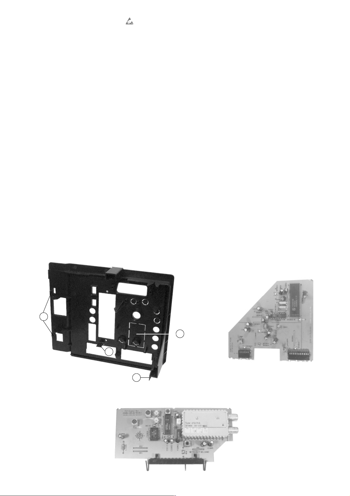
A am Chassisrahmen lösen (Fig.1), Rastnasen B ausrasten und Abdeckung wegklappen
C ausbrechen (Fig.1) und beiliegende Abdeckung-Splitter in den Durchbruch einsetzen,
ESD
PIP-Abgleich
- Gerät ausschalten
- PIP-Taste der Fernbedienung gedrückt halten und Gerät mit dem Netzschalter einschalten
- PIP-Bild erscheint auf dem Bildschirm
- PIP-Bild auf vertikale/horizontale Lage mit den Tasten
- Mit "OK" bestätigen
GB
Fitting Instructions
ǷǸǵǶ einstellen
Module SET PIP 5, Order Number G.AE 2000
for Digi Basic 3 TV chassis
consisting of: PIP Module 29504 206 0100
Signal Module with Splitter 29504 212 0200
Cover, Splitter 29700 645 2101
Fitting Instructions 72010 024 3000
Coax Connector 29303 353 2400
Änderungen vorbehalten / Subject to alteration • 72010 024 3001 • 0999 • E-BS33
Page 2
Attention: Observe MOS regulations
Assembly:
- Disconnect the mains plug
- Loosen the rear of the cabinet and pull it backwards, unplug the connector of the subwoofer from the Click Fit board (option),
remove the rear of the cabinet
- Undo the screws on the left/right of the chassis and pull the chassis to the back
- Loosen the securing bracket
- Remove the cover:
Detach catch
- Press the 2 catches of the AF Module on the bottom of the chassis together and remove the AF Module
- Pull off the earth ring from the tuner input of the IF Module
- Press the 2 catches of the IF Module on the bottom of the chassis together and remove the IF Module
- Attach the PIP Module to the chassis (ST-PI1 and ST-PI2)
- Plug the PIP Signal Module into the multipoint connector between the AF and IF Amplifier
- Refit the IF Module, attach the earth ring to the tuner input
- Insert the AF Module
- Lock in the securing bracket (take care of the cable layout)
- Break the prepunched cutout
lock it in
- Connect the coax connector to the IF Tuner and the PIP Signal Tuner
- Slide the chassis in and fasten it with the 2 screws (left/right)
- Plug the connector of the subwoofer into the Click Fit board (option) and refit the rear of the cabinet
- Close the TV set
Connect the mains plug and switch the TV set on
A at the side from the chassis frame (Fig.1), disengage catches B and hinge away the cover
C off the cover (Fig.1), fit the enclosed splitter cover into the cutout, attach the cover and
ESD
PIP Adjustment
- Switch the TV set off
- Press and hold the PIP button on the remote control handset and switch the TV set on with the mains switch
- The PIP appears on the screen
- Set the vertical/horizontal PIP position using the
- Confirm with "OK"
Fig.1
ǷǸǵǶ buttons
PIP-Baustein / PIP Module
B
C
B
Signal Modul mit Splitter
Signal Module with Splitter
A
 Loading...