

Page 1
D
1
Montageanleitung
Satelliten-Einbau-Receiver SER 520 Best. Nr. G.AE 1700
für Planatron PW 110-520/9 PAL PLUS
bestehend aus: SAT-Baustein 29305 302 0200
Montageanleitung 72010 021 7000
Bedienungsanleitung 28017 942 0500
Hinweis: Es sind beide Steckplätze mit SER 520 zu bestücken.
Achtung: MOS-Vorschriften beachten
ESD
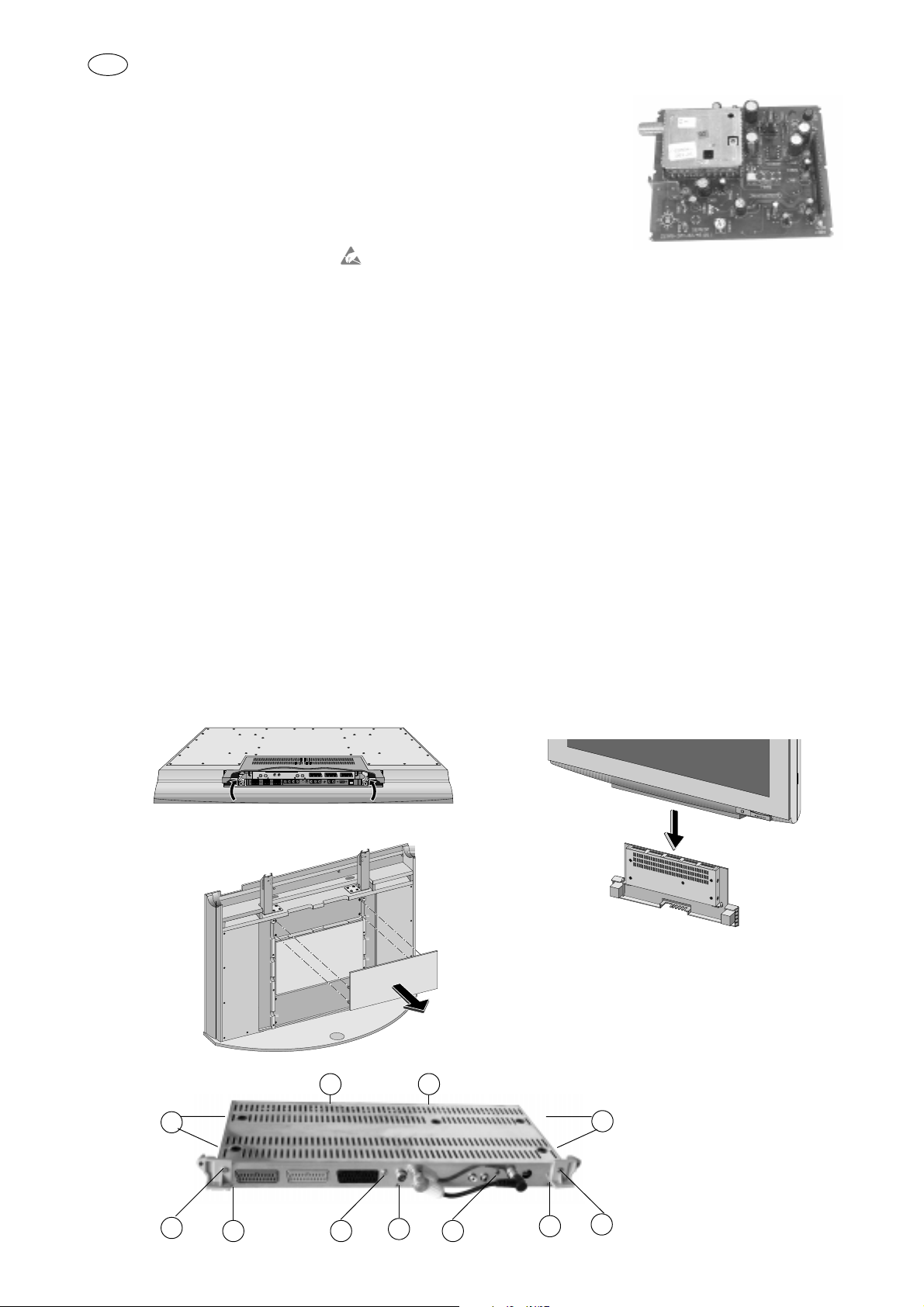
Montage:
- Netzstecker ziehen
- Abdeckung für Anschlußbuchsen abnehmen (nur bei Geräten mit Wandhalterung)
- Abdeckung (Fig. 3) nach hinten abziehen (nur bei Geräten mit Standfuß)
- Anschlußbox aus der Docking Station nach hinten ziehen (nur bei Geräten mit Docking Station)
- Anschlußbox entriegeln (Fig.1/2) und abziehen (entfällt bei Geräten mit Docking Station)
- 2 Schrauben D herausschrauben (Fig. 4), (entfällt bei Geräten mit Docking Station)
- 4 Schrauben A seitlich der Anschlußbox herausschrauben (Fig. 4)
- 5 Schrauben B herausschrauben (Fig. 4)
- Gehäuseboden abnehmen
- 2 Schrauben C herausschrauben (Fig. 4)
- 5 Schrauben aus Druckplatte herausschrauben
- Druckplatte aus dem Gehäuse herausnehmen
- 2 Abstandshalter aus den Druckplatten der terrestrischen Signal-Bausteine ausrasten
- Terrestrische Signal-Bausteine durch SAT-Bausteine ersetzen
- 2 Abstandshalter in die Druckplatten der SAT-Bausteine einrasten
- Druckplatte in Gehäuse einsetzen und mit den 5 Schrauben festschrauben
- Gehäuse schließen und verschrauben
- Anschlußbox in Gerät einschieben und verriegeln, bei Geräten mit Docking Station nur einschieben
- Abdeckung für Anschlußbuchsen aufsetzen und einrasten (nur bei Geräten mit Wandhalterung)
- Abdeckung bei Geräten mit Standfuß wieder anbringen (Fig.3)
Netzstecker einstecken und Gerät einschalten
Gerät startet mit ATS-Reset (Menüführung)
Fig. 1 Fig. 2
1
IN TERR. OUT
TERR. IN
LAUDIO OUT R
TERR. SAT 2
EURO AV 3 EURO AV 2 EURO AV 1 TERR. SAT 1
Fig. 3
Fig. 4
B
B
A
A
D
B
C C
B
Änderungen vorbehalten / Subject to alteration • 72010 021 7000 • E-BS 33 • 0799
B
D
Page 2

GB
1
Fitting Instructions
Built-in Satellite Receiver SER 520 Order No. G.AE 1700
for Planatron PW 110-520/9 PAL PLUS
consisting of: SAT Module 29305 302 0200
Fitting Instructions 72010 021 7000
Operating Instructions 28017 942 0500
Note: A SER 520 is to be inserted into both positions provided on the module.
Attention: Observe MOS regulations
ESD
Assembly:
- Disconnect the mains plug.
- Remove the cover from the connecting sockets (only wall-mounting models)
- Pull the cover off (Fig. 3) towards the back (only models with stand)
- Pull the connecting box out of the Docking Station towards the back (only models with Docking Station)
- Unlock the connecting box (Fig.1/2) and remove it (not applicable to models with Docking Station)
- Undo 2 screws D (Fig. 4), (not applicable to models with Docking Station)
- Undo 4 screws A at the sides of the connecting box (Fig. 4)
- Undo 5 screws B (Fig. 4)
- Remove the bottom of the casing
- Undo 2 screws C (Fig. 4)
- Undo 5 screws of the printed circuit board
- Take the printed circuit board out of the casing
- Remove the 2 spacers from the circuit boards of the terrestrial Signal Modules
- Replace the terrestrial Signal Modules by the SAT Modules
- Insert the 2 spacers into the circuit boards of the SAT Modules
- Put the circuit board into the casing and fasten it with the 5 scews
- Close the casing and fasten the screws
- Slide the connecting box into the set and secure it. The connecting box is not to be secured in models with Docking Station;
just slide it in.
- Attach the cover for the connecting sockets and secure it (only wall-mounting models)
- Attach the cover to models with stand (Fig. 3)
Insert the mains plug and switch the TV set on.
The TV set starts with ATS-Reset (menu guide).
Fig. 1 Fig. 2
1
IN TERR. OUT
TERR. IN
LAUDIO OUT R
TERR. SAT 2
EURO AV 3 EURO AV 2 EURO AV 1 TERR. SAT 1
Fig. 3
Fig. 4
A
B
B
A
D
B
C C
B
B
D
 Loading...