

Page 1
Service Manual
Grundig Service
Hotline Deutschland...
Technik:
TV
TV
SAT
VCR/LiveCam
HiFi/Audio
Car Audio
T elekommunikation
Planatron
Ersatzteil-Verkauf: ...Mo.-Fr. 8.00-19.00 Uhr
(8.00-22.00 Uhr)
...Mo.-Fr. 8.00-18.00 Uhr
0180/52318-41
0180/52318-49
0180/52318-48
0180/52318-42
0180/52318-43
0180/52318-44
Fax:
Telefon:
Fax:
0180/52318-45
0180/52318-51
0180/52318-99
0180/52318-40
0180/52318-50
HiFi
M 14
(G.LI 0251)
Service
Manual
M 14
Materialnr./Part No.
72010 759 4500
Zusätzlich erforderliche
Unterlagen für den Komplettservice
Additionally required
Service Manuals for the Complete Service
Service
Manual
Sicherheit
Safety
Materialnr./Part No.
72010 800 0000
Btx * 32700 #
Materialnummer
Part Number 72010 759 4500
Änderungen vorbehalten
Subject to alteration
Printed in Germany
E-BS 38 0499
8002/8012, 8005/8015, 8006/8016
http:\\www.grundig.de
Page 2

Allgemeiner Teil / General Section M 14
Es gelten die Vorschriften und Sicherheitshinweise gemäß dem Service Manual "Sicherheit",
Materialnummer 72010 800 0000, sowie zusätzlich die eventuell abweichenden, landesspezifischen Vorschriften!
Inhaltsverzeichnis
Seite
Allgemeiner Teil ........................... 1 - 2 … 1 - 16
Meßgeräte.................................................................................. 1 - 2
Service-Hinweis ......................................................................... 1 - 3
Technische Daten ...................................................................... 1 - 3
Bedienhinweise.......................................................................... 1 - 4
Ausbauhinweise....................................................................... 1 - 11
Abgleichvorschriften ......................2 - 1 ... 2 - 2
Platinenabbildungen
und Schaltpläne ........................... 3 - 1 … 3 - 28
Blockschaltplan .......................................................................... 3 - 1
Schaltpläne:
Tuner-Teil ............................................................................... 3 - 2
Hauptplatte, Kopfhörerplatte .................................................. 3 - 7
Steuerplatte LED-Platte ....................................................... 3 - 11
Tastenplatte, CD-Tastenplatte ............................................. 3 - 15
Leistungsplatte ..................................................................... 3 - 17
CD-Motor-Steuerplatte ......................................................... 3 - 21
CD-Platte.............................................................................. 3 - 23
Platinenabbildungen:
Hauptplatte, Kopfhörerplatte .................................................. 3 - 5
Steuerplatte LED-Platte ....................................................... 3 - 13
Tastenplatte, CD-Tastenplatte ............................................. 3 - 15
Leistungsplatte ..................................................................... 3 - 19
Display ..................................................................................... 3 - 26
Verdrahtungsplan..................................................................... 3 - 27
The regulations and safety instructions shall be
valid as provided by the "Safety" Service Manual,
part number 72010 800 0000, as well as the
respective national deviations!
Table of Contents
Page
General Section............................ 1 - 2 … 1 - 16
Test Equipment.......................................................................... 1 - 2
Service Hint................................................................................ 1 - 3
Technical Data ........................................................................... 1 - 3
Operating Instructions................................................................ 1 - 7
Disassembly Instructions ......................................................... 1 - 11
Adjustment Procedures..................2 - 3 ... 2 - 4
Layout of the PCBs
and Circuit Diagrams ................... 3 - 1 … 3 - 28
Block Diagram............................................................................ 3 - 1
Circuit Diagrams:
Tuner Part .............................................................................. 3 - 2
Main Board, Headphone Board.............................................. 3 - 7
Control Board, LED Board ................................................... 3 - 11
Key Board, CD Key Board ................................................... 3 - 15
Power Board ........................................................................ 3 - 17
CD Motor Control Board....................................................... 3 - 21
CD Board ............................................................................. 3 - 23
Layout of the PCBs:
Main Board, Headphone Board.............................................. 3 - 5
Control Board, LED Board ................................................... 3 - 13
Key Board, CD Key Board ................................................... 3 - 15
Power Board ........................................................................ 3 - 19
Display ..................................................................................... 3 - 26
Wiring Diagram ........................................................................ 3 - 27
Explosionszeichnungen
und Ersatzteillisten ........................ 4 - 1 … 4 - 6
Allgemeiner Teil
Meßgeräte
Beachten Sie bitte das GRUNDIG Meßtechnik-Programm, das Sie
unter folgender Adresse erhalten:
Grundig AG Geschäftsbereich Instruments Test- und Meßsysteme
Würzburger Str. 150, D-90766 Fürth
Tel.: 0911 / 703-4118, Fax: 0911 / 703-4130
eMail: instruments@grundig.de, Internet: http://www.grundig-instruments.de
Exploded Views
and Spare Parts Lists .................... 4 - 1 … 4 - 6
General Section
Test Equipment
Please note the GRUNDIG Catalog "Test and Measuring Equipment"
obtainable from:
1 - 2 GRUNDIG Service
Page 3
Allgemeiner Teil / General SectionM 14
Service-Hinweis
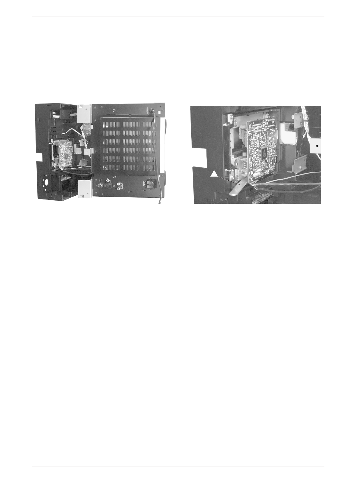
Service-Stellung für das Arbeiten an der CD-Laufwerkplatine.
Vor Beginn der Servicearbeiten sollte sich die Test-CD bereits in PlayStellung im CD-Laufwerk befinden.
Das CD-Teil ohne die Leitungen zu lösen ausbauen (siehe Ausbauhinweise auf Seite 1 - 11). Danach das Gerät mit dem CD-Teil auf die linke
Geräteseite legen (Fig. A). Damit sich die eingelegte CD frei drehen
kann, muß das CD-Laufwerk gestützt werden. Am besten eignet sich
ein circa 2mm starker und maximal 10mm breiter Unterlegstreifen a
der, wie in Fig. B gezeigt, zwischen dem CD-Laufwerk und dem CDLaufwerkrahmen eingeschoben wird.
Service Hint
Position for service works on the CD drive mechanism pcb
Before starting the service works, the Test CD should be already in
Play position in the CD drive mechanism.
Dismantle the CD Unit without disconnecting the leads (see Disassembly
Instructions on page 1 - 11). Subsequently, put the system with the CD
Unit down on its left side (Fig. A). To ensure that the loaded CD turns
smoothly, the CD drive mechanism is to be supported. Preferrably, use
a strip a of any suitable material, about 2mm thick and a maximum of
10mm wide, and insert it between the CD drive mechanism and the
frame as shown in Fig. B.
a
Fig. A Fig. B
Technische Daten
SPANNUNGSVERSORGUNG
Netzbetrieb: ........................................................ 230 Volt, 50/60Hz
Ausgangsleistung (1% THD):
Musikleistung ................................................................. 2 x 20W
Sinusleistung ................................................................. 2 x 10W
Stereo-Kopfhörer-Klinkenbuchse: .................................... 3,5mm ø
RUNDFUNKTEIL
Wellenbereiche:
FM ...................................................................... 87,5…108MHz
MW ...................................................................... 522…1620kHz
Zwischenfrequenzen:
FM ................................................................................ 10,7MHz
MW ................................................................................. 450kHz
Antennen:
FM .........................................................................Drahtantenne
MW ................................................................... Rahmenantenne
CD-TEIL
Frequenzübertragungsbereich: ................................ 40Hz…20kHz
Geräuschspannungsabstand (bewertet): ............................... 65dB
Technical Data
POWER SUPPLY
Mains operation ................................................. 230 Volt, 50/60 Hz
Output power (1% THD):
Socket for stereo headphones: ........................................ 3.5mm ø
RADIO SECTION
Wavebands:
Intermediate frequencies:
Aerials:
CD SECTION
Frequency range: ..................................................... 40Hz…20kHz
S/N ratio (weighted):............................................................... 65dB
Music power .................................................................. 2 x 20W
Nominal power............................................................... 2 x 10W
FM ...................................................................... 87.5…108MHz
MW ..................................................................... 522…1620 kHz
FM ................................................................................ 10.7MHz
MW ................................................................................. 450kHz
FM ..........................................................................wire antenna
MW ....................................................................... Loop antenna
CASSETTENTEIL
Tonträger: ...............................Compact-Cassette nach DIN 45516
Spurlage: ...................................................Viertelspur international
Bandgeschwindigkeit:.................................................. 4,76cm/sec.
Motor: ..............................................................................DC-Motor
Frequenzübertragungsbereich: ................................ 80Hz…10kHz
Geräuschspannungsabstand (bewertet): ............................... 48dB
Gleichlauffehler:................................................................... 0,25%
Automatik: ........................Aussteuerungsautomatik bei Aufnahme
......... Automatisch Auslösen der Tasten am Bandende
GRUNDIG Service 1 - 3
CASSETTE SECTION
Cassette: ..................................... Compact cassette to DIN 45516
Track system: ......................................... International quartertrack
Tape speed: ................................................................ 4.76cm/sec.
Motor: .............................................................................. DC motor
Frequency range: ..................................................... 80Hz…10kHz
S/N ratio (weighted):............................................................... 48dB
Wow and flutter: ................................................................... 0.25%
Automatic functions: .................. Automatic recording level control
............Automatic button release at tape end
Page 4
1 - 4 GRUNDIG Service
Allgemeiner Teil / General Section M 14
Bedienhinweise
Dieses Kapitel enthält Auszüge aus der Bedienungsanleitung. Weitergehende Informationen entnehmen Sie bitte der gerätespezifischen
Bedienungsanleitung, deren Materialnummer Sie in der entsprechenden Ersatzteilliste finden.
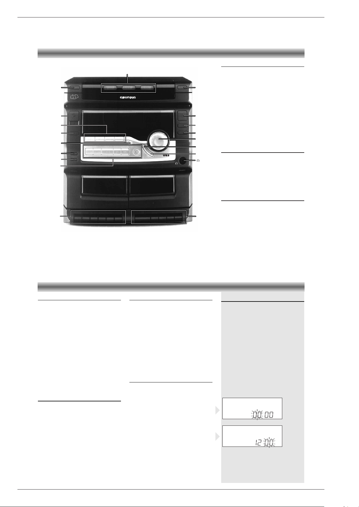
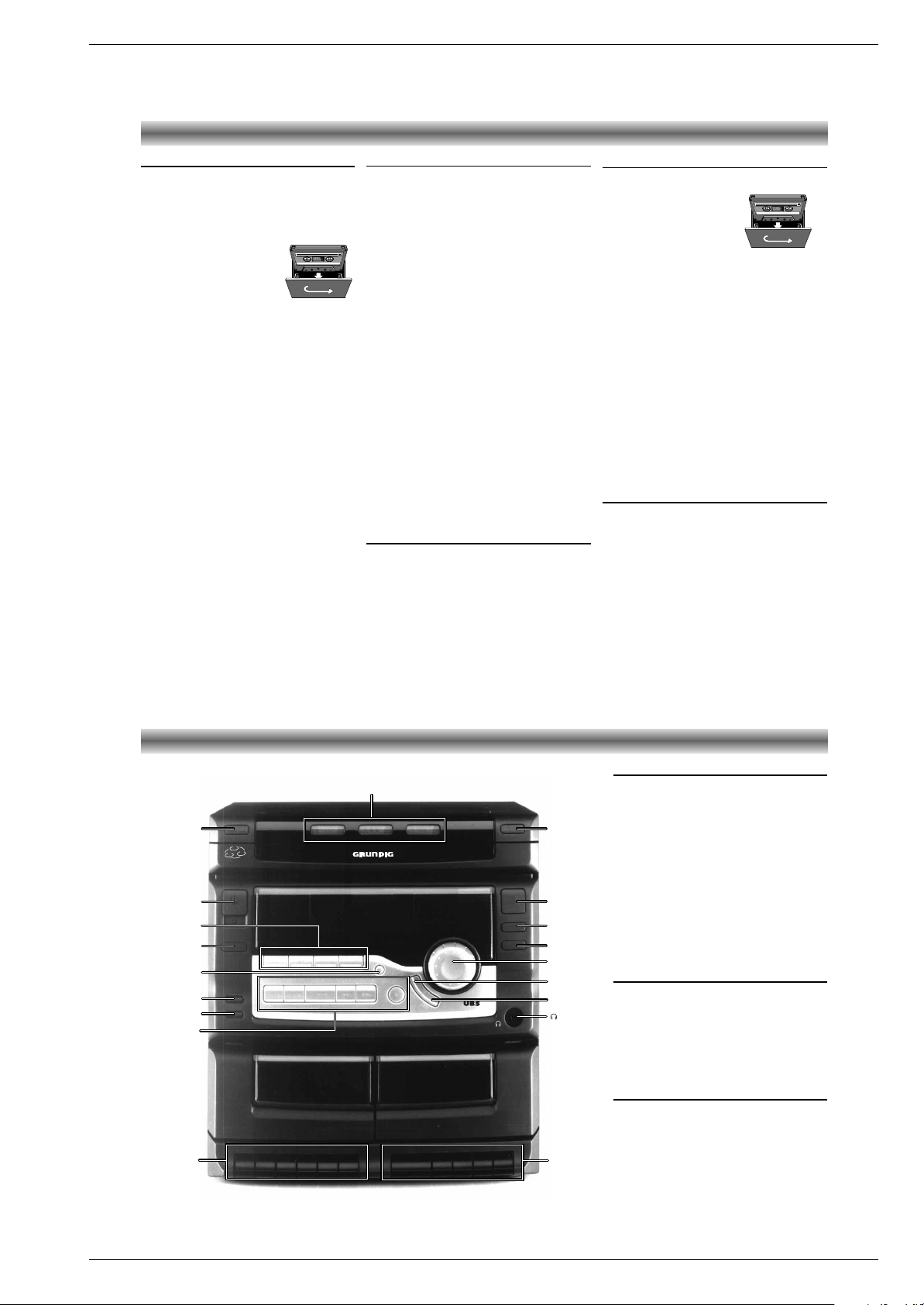
BEDIENELEMENTE AN DER VORDERSEITE
Bedienelemente Verstärker
ON/OFF y – Gerät einschalten oder in Bereitschaftsfunktion bringen. Die STANDBY LED (unter
der ON/OFF y-Taste) 6 erscheint, solange das
Gerät mit dem Netz verbunden ist.
SOURCE: AUX/TAPE/CD/TUNER – Gerät
einschalten und Wählen der Signalquelle. Wird
CD gedrückt, beginnt bei eingelegter CD sofort
die Wiedergabe.
VOLUME – Mit diesem Regler passen Sie die
Lautstärke an.
UBS (Ultra Bass System) – Zum Ein- und
Ausschalten der Baßverstärkung
PRESET EQ – Zum Wählen der ge
wünschten
Klangeffekte: ROCK, POP, JAZZ, CLASSIC oder
kein Effekt.
p – Kopfhöreranschluß
Bedienelemente Radio
TUNER – Radio einschalten und Wellenbereich
MW oder FM (UKW) einstellen
.
PRESET QR– Wählen eines
gespeicherten Radiosenders.
TUNING/SKIP/SEARCH ST–
Drücken
Sie die Taste T, um höhere
bzw. S, um
niedrigere Frequenzen auszuwählen.
PROGRAM – Speichern von Radiosendern.
Uhren-/Timer-Regler
PRESET QR– Einstellen der Stunden und
Minuten für Uhr und Timer.
TIME/SLEEP – Drücken Sie einmal zum Einstellen
oder Anzeigen der Uhr oder Timer.
TIMER ON – Timer einschalten.
TIMER OFF – Timer ausschalten.
PROGRAM – Speichern von Uhrzeit oder Timer-
einstellungen.
3
1
2
OPEN/CLOSE
DISC CHANGE
PROGRAM
REPEAT
RANDOM
ULTRA BASS SYSTEM
DISC 1 DISC 2 DISC 3
P
R
E
S
E
T
E
Q
U
B
S
CD STOP
REC/PLAYBACK
RECORD PLAY REWIND F.FWD STOP/EJ. PAUSE PLAY REWIND
F.FWD
STOP/EJ.
PAUSE
TAPE A
PLAYBACK
TAPE B
CD SYNCHRO RECORDING
AUTO RECORD LEVEL CONTROL
FULL AUTO STOP
NORMAL/HIGH SPEED DUBBING
TUNING/SKIP/SEARCHPLAY/PAUSEPRESET
PLL SYNTHESIZER TUNER
3 CD MULTICHANGER 1 BIT D/A CONVERTER
AUX TAPE CD TUNER
HI-SPEED
DUBBING
VOLUME
ON/OFF
CD CHANGER
STANDBY
TIME/SLEEP
TIMER ON
TIMER OFF
9
ST2;QR
M14
DISC
CHANGE
PROGRAM
REPEAT
RANDOM
VOLUME
PRESET EQ
UBS
HI-SPEED
DUBBING
ON/OFF y
TIME/SLEEP
SOURCE
OPEN/CLOSE
TIMER ON
TIMER OFF
DISC SELECT
TAPE B
TAPE A
CD/RADIO
CONTROL
BEDIENELEMENTE BEDIENUNG
p (Kopfhörer)-Öffnung
Der Kopfhörerstecker bietet privates
Hörvergnügen.
• Möchten Sie Kopfhörer verwenden, setzen Sie
die Lautstärke auf das Minimum und führen Sie
einen 3.5 mm Ministecker der Kopfhörer in
die p- Öffnung.
– Die Lautsprecher werden abgeschaltet, sobald
der Anschluß des Steckers erfolgt ist.
.
.
.
.
Bedienelemente CD-Wechsler
OPEN/CLOSE / – Öffnen oder Schließen des
CD Faches
DISC SELECT 1~3 – Auswahl einer CD, die
wiedergegeben werden soll.
DISC CHANGE – Bewegt den drehbaren CDTeller, um eine CD auswählen zu können.
PROGRAM – Programmieren von Titeln.
REPEAT - zur Wiederholung eines Stücks, einer
oder aller drei CDs.
RANDOM - Wiedergabe in zufälliger Reihen-
folge.
PLAY/PAUSE B; – CD-Spieler einschalten und
Beginnen oder Unterbrechen einer CD Wiedergabe.
9 –
Beenden der CD Wiedergabe oder Löschen
eines Programmes
S TUNING/SKIP/SEARCH T – Kurz
drücken: Titelsprung vor- oder rückwärts.
Halten Sie diese Taste während der Wiedergabe gedrückt, um die ausgewählte CD in
Vorwärts- oder Rückwärtsrichtung zu durchlaufen.
Bedienelemente Cassettendeck
TAPE B – Bedienelemente an Deck B
PLAY – Starten der Wiedergabe.
REWIND – Schneller Rücklauf.
F.FWD. – Schneller Vorlauf.
STOP/EJ. – Stoppen des Bandlaufs und
Öffnen des Cassettenfachs.
PAUSE – Unterbrechen der Wiedergabe.
TAPE A – Bedienelemente an Deck A
RECORD – Star ten der Aufnahme.
PLAY – Starten der Wiedergabe.
REWIND – Schneller Rücklauf.
F.FWD. – Schneller Vorlauf.
STOP/EJ. – Stoppen des Bandlaufs und
Öffnen des Cassettenfachs.
PAUSE – Unterbrechen der Wiedergabe.
HI SPEED DUBBING – Kopieren von Deck B
nach A in hoher Geschwindigkeit.
Ein- und Ausschalten des Geräts
• Drücken Sie die Taste ON/OFF y am Gerät
oder auf der Fernbedienung, um die Anlage
einzuschalten.
• Drücken Sie nochmals ON/OFF y, um die
Anlage auszuschalten.
Hinweis: Selbst wenn Sie die Anlage ausschalten, bleibt die Stromversorgung über das Netz
erhalten.
Um die Stromversorgung zur Anlage vollständig
zu unterbrechen, den Netzstecker ziehen.
Automatische Stromeinschaltung
• Durch Drücken von TUNER, CD, TAPE oder
AUX auf dem Hauptgerät wird das Gerät
automatisch eingeschaltet und die betreffende
Quelle gewählt.
Einstellen der Uhrzeit
•
Wenn das Gerät eingeschaltet ist,
die
TIME/SLEEP-Taste drücken und danach die
Taste PROGRAM.
– Die Stundenanzeige blinkt auf dem Display.
•
Die Stunden mit PRESET Q und R
am
Gerät oder PRESET #$ auf der
Fernbedienung einstellen.
• Drücken Sie die Taste PROGRAM erneut.
• Die Minuten mit PRESET Q und R am
Gerät oder PRESET #$ auf der
Fernbedienung einstellen.
• Drücken Sie die Taste PROGRAM nochmals
um die Zeit zu speichern.
– Die Uhr beginnt zu laufen.
Hinweis
Bei einem Stromausfall wird die Uhrzeit-Einstellung
gelöscht und auf dem Display blinkt 00:00.
Die Uhrzeit soll dann neu eingestellt werden.
Page 5
GRUNDIG Service 1 - 5
M 14 Allgemeiner Teil / General Section
Lautstärkeregelung
• Drehen Sie den Lautstärkeregler VOLUME
nach rechts, um die Lautstärke anzuheben.
Drehen Sie den Regler VOLUME nach links,
um die Lautstärke herunterzudrehen.
• Sie können auch die Taste VOLUME C oder D
auf der Fernbedienung drücken.
– Im Display erscheint der Lautstärkepegel.
– Beim Einschalten des Geräts wählt dieses
immer die vorherige Einstellung der Lautstärke.
MUTE
• Drücken Sie MUTE auf der Fernbedienung, um
den Ton für kürzere Zeit abzuschalten.
– MUTE blinkt im Display.
• Nochmaliges Drücken der Taste MUTE oder
Drücken der Tasten VOLUME C oder D auf
der Fernbedienung stellt den Ton wieder her.
– Die Anzeige MUTE erlischt damit.
UBS Ultra Bass System
• Die Taste UBS drücken, um den BaßFrequenzgang zu verstärken.
– Die UBS-Anzeige leuchtet im Display.
• Durch erneutes Drücken von UBS wird die
Funktion abgeschaltet.
Equalizer-Einstellungen
Die PRESET EQ-Funktion schafft eine realistische
Atmosphäre für die gewählte Musikart.
• Um den gewünschten speziellen Klangeffekt
zu genießen, die Taste PRESET EQ mehrmals
drücken.
– Die jeweilige Klangeinstellung erscheint im
Display: ROCK, POP, JAZZ, CLASSIC oder
kein Effekt.
KLANGEINSTELLUNG RADIO
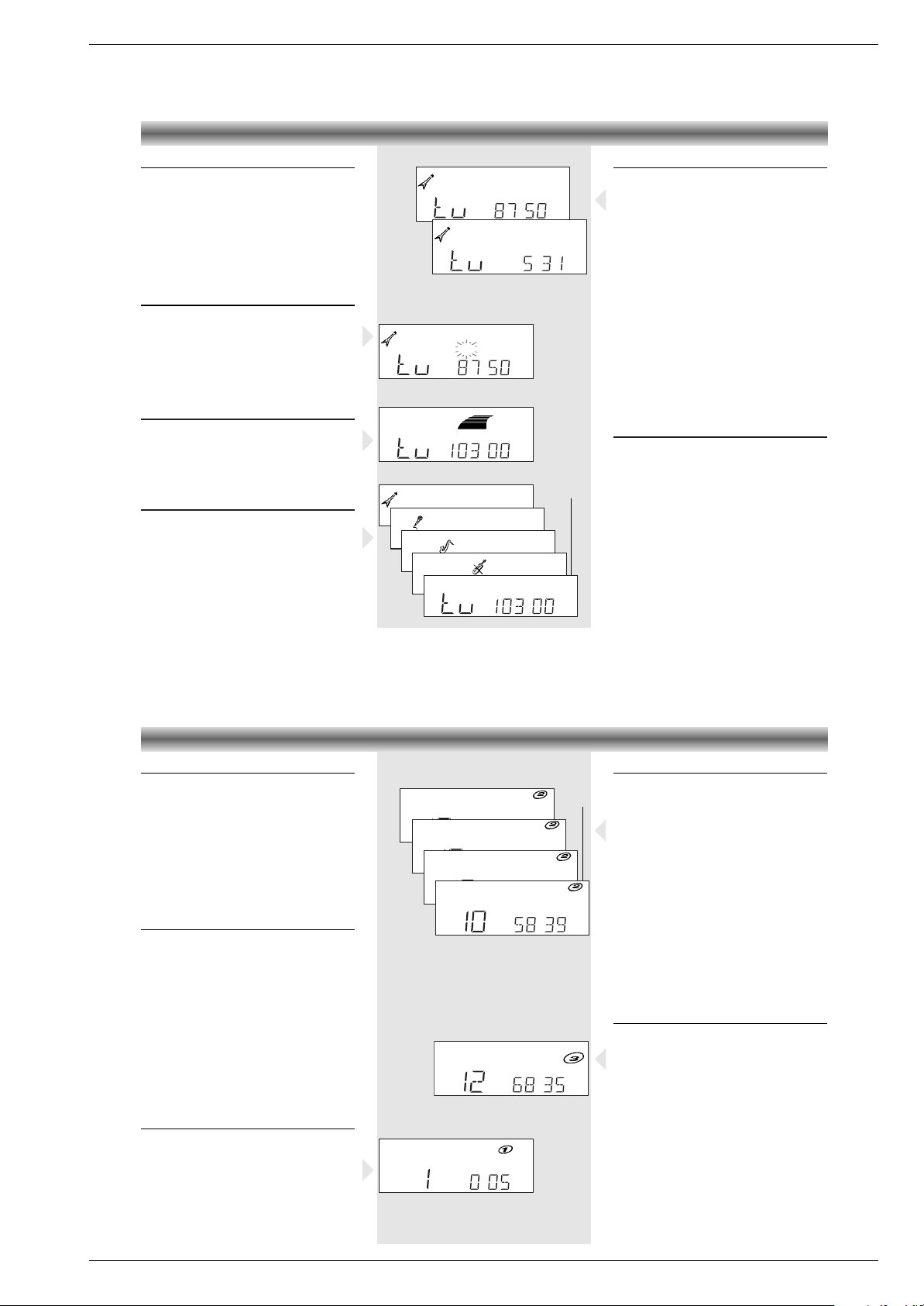
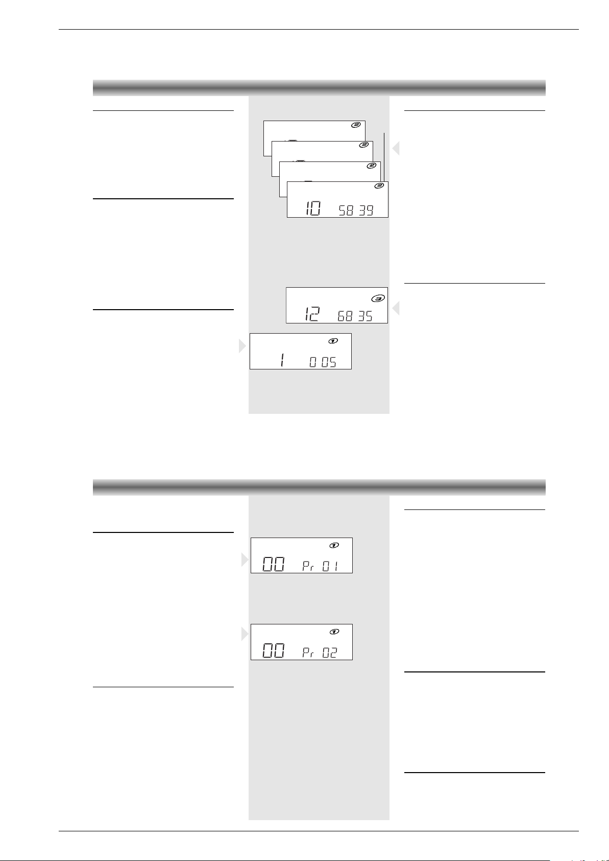
Radiosender einstellen
•
TUNER drücken, um TUNER und den gewünschten
Wellenbereich MW/FM (UKW) einzustellen.
–
Die aktuelle Frequenz wird im Display angezeigt.
• Beim Empfangen eines UKW-Senders, stellt
die Anlage automatisch auf FM STEREO. Ist
der Stereo-Empfang gestört, können Sie auf
FM MONO-Empfang schalten, indem Sie
nochmals
TUNER
drücken.
– Wählen Sie MONO, erlischt die
STEREO
-
Anzeige im Display.
•
TUNING/SKIP/SEARCH S oder T länger
als eine Se
kunde drücken. Die Senderabstimmung läuft, bis ein Sender mit ausreichendem
Radiosignal gefunden ist.
• Diese Schritte wiederholen, bis der gewünschte
Sender erreicht ist.
•
Wenn Sie einen schwachen Sender einstellen
möchten drücken Sie mehrmals kurz TUNING/-
SKIP/SEARCH S oder T bis die gewünsch-
te Frequenz
angezeigt wird und/oder bester
Empfang erreicht wurde.
Radiosender speichern
Bis zu 24 Sender können für die Wellenbereic
he
FM und MW im Speicher aufgenommen werden.
Manuelle Programmierung
• Zu speichernden Sender einstellen.
•
PROGRAM drücken.
MEMO
, die Frequenz und
die Speicherplatznummer erscheinen im Display.
• Die Tasten PRESET QRdrücken um die
gewünschte Speicherplatznummer zu wählen.
• PROGRAM erneut drücken um den Sender zu
speichern. Die Speichernummer erscheint im
Display und nach 1 Sekunde die Frequenz.
• Oben beschriebenen Vorgang für jeden zu
speichernden Sender wiederholen.
•
Möchten Sie einen gespeicherten Sender anhören,
wählen Sie die gewünschte Speicher-
platznummer mit den Tasten PRESET QR.
ROCK
POP
JAZZ
CLASSIC
MHz
.
➥
➥
➥
➥
➥
STEREO
FM
UBS
MHz
.
STEREO
FM
ROCK
STEREO
MUTE
MHz
FM
.
ROCK
STEREO
MHz
FM
.
ROCK
kHz
➥
➥
MW
Wahl eines anderen Titels
• Durch wiederholtes Drücken der Taste
TUNING/SKIP/SEARCH T gelangen Sie
an den Anfang der folgenden Titel.
Mit TUNING/SKIP/SEARCH S an den
Anfang der vorherigen Titel.
• Drücken Sie TUNING/SKIP/SEARCH S nur
einmal, gelangen Sie an den Anfang des
laufenden Titels.
Rasches suchen einer Passage
Rasches Suchen kann im Wiedergabe- oder
Pausemodus aktiviert werden.
• TUNING/SKIP/SEARCH S oder T
gedrückt halten, bis die gewünschte Stelle
erreicht ist.
• Sobald S oder T losgelassen wird,
erfolgt wieder normale Wiedergabe.
Hinweis:
Während der Suche wird der Ton schneller als
normal und mit reduzierter Lautstärke
wiedergegeben.
INTRO-Funktion
• Drücken Sie die Taste INTRO auf der
Fernbedienung, um die ersten 10 Sekunden
jedes Titels der gewählten CD abzuspielen.
–
INTRO
erscheint im Display.
• Drücken Sie die Taste INTRO noch einmal, um
die Wiedergabe eines bestimmten Titels
normal fortzusetzen.
CD-SPIELER
TRACK
INTRO
.
.
B
TRACK
RAND
.
.
➥
➥
➥
➥
TRACK
REPEAT1
TRACK
REPEAT
DISC
1
.
.
.
TRACK
REPEAT
ALLDISC
TRACK
.
.
Repeat-Funktion
Wenn Sie CDs oder ein CD-Programm mehrmals
hören möchten, können Sie dies mit der REPEATFunktion tun.
• Drücken Sie REPEAT am Gerät oder auf der
Fernbedienung.
– Der Wiederholstatus ändert sich von
REPEAT 1
in
REPEAT DISC
in
REPEAT ALL
und
repeat aus.
–
REPEAT 1
: Ein bestimmter Titel wird ständig
wiederholt.
–
REPEAT DISC
: Die aktuelle CD wird von
Anfang bis Ende wiederholt.
–
REPEAT ALL
: Alle eingelegten CDs werden
von Anfang bis Ende wiederholt.
–
REPEAT PROG
: Wird REPEAT im Programmodus gedrückt, werden die programmierten
Titel einer oder aller CDs wiederholt.
Random-Funktion
• Drücken Sie RANDOM am Gerät oder auf der
Fernbedienung.
– Im Display erscheint
RAND
.
• Zum Starten des Abspielens auf PLAY/PAUSE
B; drücken.
– Die Titel und CDs werden in zufälliger
Reihenfolge abgespielt.
• Drücken Sie noch einmal RANDOM, um zum
normalen Abspielen zurückzukehren.
Hinweis:
Die Funktion RANDOM kann auch in Kombination mit der REPEAT-Funktion benutzt werden.
Sie können alle Titel aller CDs in zufälliger
Reihenfolge abspielen.
Page 6
1 - 6 GRUNDIG Service
Allgemeiner Teil / General Section M 14
CD-SPIELER
Beim Speichern eines Programms können bis zu
32 Titel in jeder beliebigen Reihenfolge
aufgenommen werden.
Speichern eines Programms
• Legen Sie CD(s) ein (siehe Einlegen von CDs).
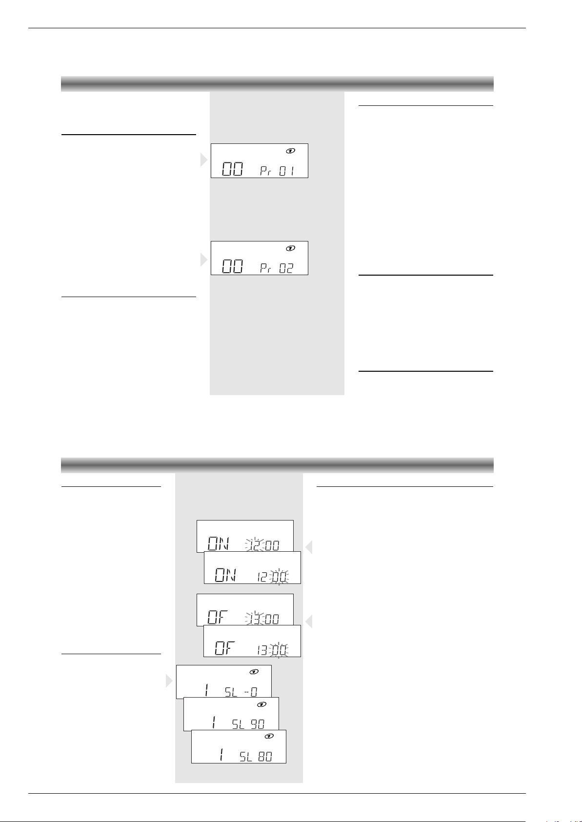
• Drücken Sie in Stellung STOP, die Taste
PROGRAM.
TRACK OO und Pr.01 erscheint im Display.
• Drücken Sie die gewünschte DISC SELECTTaste.
• Drücken Sie die entsprechende
TUNING/SKIP/SEARCH S oder T-
Taste, um den gewünschten Titel auszuwählen.
– Die Nummer unter TRACK zeigt die jeweils
ausgewähle Titelnummer an.
• Nach Auswahl des Titels drücken Sie erneut
PROGRAM.
– Der Titel ist jetzt gespeichert und im Display
erscheint: TRACK OO und Pr.02.
• Wiederholen Sie die oben genannten Schritte,
um weitere Titel zu speichern.
Überprüfen der programmierten
Titelfolge
• Nach dem Programmieren kann die programmierte Titelfolge durch wiederholtes Drücken
von PROGRAM überprüft werden.
TRACK
PROG
.
TRACK
PROG
.
Abspielen eines Programms
• Drücken Sie die Taste PLAY/PAUSE B;, um
ein Programm wiederzugeben.
• Stellen Sie die Lautstärke nach Belieben ein.
– Die Wiedergabe endet durch Drücken der CD
STOP
9
-Taste oder am Ende des Programms.
– Erneut PROGRAM drücken. Das Symbol
PROG
verschwindet (für normale Wiedergabe). Die Reihenfolge des Programms bleibt
jedoch im Speicher erhalten.
• Zum nochmaligen Abspielen des Programms
drücken Sie erst die Taste PROGRAM.
– Das Symbol
PROG
erscheint.
• Drücken Sie anschließend die Taste
PLAY/PAUSE B;.
Hinweis:
Während des Abspielens eines Programms können mit den Tasten TUNING/SKIP/-
SEARCH S und T die gewünschten
programmierten Titel angewählt werden.
Hinzufügen von Titeln zu einem
Programm
• Drücken Sie mehrmals die Taste PROGRAM
bis der Titel, den Sie ersetzen wollen, oder
der erste freie Speicherplatz im Display
erscheint.
• Speichern Sie den nächsten Titel gemäß der
beschriebenen Schritte.
– Neue Titel können dem Programm nur am
Ende hinzugefügt werden.
– Während der Wiedergabe können keine Titel
in das Programm aufgenommen werden.
Löschen von Programmtiteln
• Um alle gespeicherten Titel eines Programm zu
löschen, drücken Sie in Stellung STOP die
Taste OPEN/CLOSE.
Timer
Das System kann automatisch zu
einer bestimmten Uhrzeit auf CDoder TUNER-Betrieb geschaltet
werden und auf diese Weise z.B.
als Wecker dienen.
• Vor dem Einstellen des Timers
sicherstellen, daß die Uhrzeit
stimmt.
• Die Lautstärke des Timers entspricht der zuletzt gewählten
Einstellung vor dem Ausschalten
des Gerätes.
• Sofern der Timer nicht ausgeschaltet oder gelöscht wird, wirkt
er jeden Tag zur selben Zeit.
• Werden Sleep-Timer und
normaler Timer gleichzeitig
eingestellt, hat die Funktion des
Sleep-Timers Vorrang.
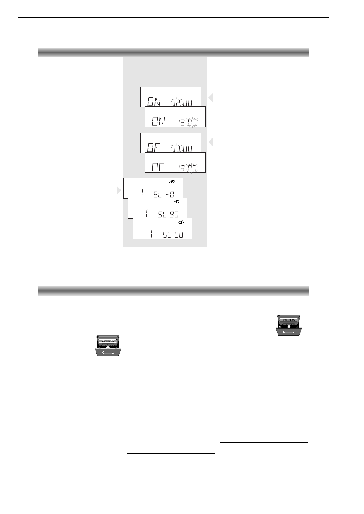
Einstellen des Sleep-Timers
Das Gerät kann zu einem vorher
eingestellten Zeitpunkt abschalten.
So können Sie beim Zuhören ruhig
einschlafen.
• Drücken Sie vier mal die Taste
TIME/SLEEP am Gerät oder auf
der Fernbedienung.
– Im Display erscheint SL.-0
• Durch wiederholtes Drücken der
PROGRAM-Taste kann die
Einschlafzeit in zehn-MinutenSchritten von 90 Minuten bis
“aus” reduziert werden.
TIMER
TRACK
.
B
TRACK
.
B
TRACK
.
B
➥
➥
SLEEP
SLEEP
SLEEP
.
.
.
.
➥
TIMER OFF
TIMER OFF
.
.
.
.
.
➥
TIMER ON
TIMER ON
Einstellen des Timers
• Die gewünschte Signalquelle CD oder TUNER wählen und
eine CD einlegen oder einen Sender einstellen.
• Drücken Sie zweimal die Taste TIME/SLEEP am Gerät oder
auf der Fernbedienung. Auf dem Display erscheint ‘
TIMER ON’
und die aktuelle Zeit
•
Drücken Sie die Taste PROGRAM. Die Anzeige der Stunden blinkt.
•
Durch Drücken von PRESET Q oder R
am Gerät oder
PRESET
# $ auf der Fernbedienung, wird die Stunde für den
Timer-Start eingestellt.
• Drücken Sie erneut die Taste PROGRAM.
Die Anzeige der Minuten blinkt.
•
Durch Drücken von PRESET Q oder R
am Gerät oder
PRESET
# $ auf der Fernbedienung,
werden die Minuten für
den Timer-Start eingestellt.
• Drücken Sie die Taste PROGRAM um die Zeit zu speichern.
• Drücken Sie erneut die Taste TIME/SLEEP. Auf dem Display
erscheint ‘
TIMER OFF
’ und die Zeit
•
Drücken Sie die Taste PROGRAM. Die Anzeige der Stunden blinkt.
•
Durch Drücken von PRESET Q oder R
am Gerät oder
PRESET
# $ auf der Fernbedienung, wird die Stunde für den
Timer-Stop eingestellt.
• Drücken Sie erneut die Taste PROGRAM.
Die Anzeige der Minuten blinkt.
•
Durch Drücken von PRESET Q oder R
am Gerät oder
PRESET
# $ auf der Fernbedienung,
werden die Minuten für
den Timer-Stop eingestellt.
• Drücken Sie die Taste PROGRAM um die Zeit zu speichern.
• Drücken Sie zweimal die Taste TIME/SLEEP.
– Die normale Radio oder CD-Anzeige erscheint.
• Drücken Sie die Taste TIMER ON. Das Symbol
TIMER leuchtet
im Display.
•
Die Taste ON/OFF y drücken, um die Anlage auszuschalten.
Mit
SLEEP TIMER kann das Gerät ebenfalls zu einem vorher
eingestellten Zeitpunkt abgeschaltet werden.
Page 7
GRUNDIG Service 1 - 7
M 14 Allgemeiner Teil / General Section
Operating Hints
This chapter contains excerpts from the operating instructions. For further particulars please refer to the appropriate user instructions the part
number of which is indicated in the relevant spare parts list.
Cassettenwiedergabe
Wiedergabe einer Cassette mit Deck A oder Deck B
• Drücken Sie TAPE, um das Cassettendeck zu
selektieren.
•
Drücken Sie auf STOP/EJ. von Deck A oder
Deck B, um das Cassettenfach zu öffnen.
• Legen Sie eine bespielte
Cassette ein mit der offenen
Bandseite nach unten und
der vollen Spule nach links.
• Zum Starten des Abspielens
auf PLAY drücken.
• Die Lautstärke mit VOLUME einstellen.
– Am Bandende der aktuellen Seite stoppt die
Wiedergabe.
• Für kurzzeitige Unterbrechungen auf PAUSE
drücken.
• Erneut auf PAUSE drücken, wenn die
Wiedergabe fortgesetzt werden soll.
• Zum Stoppen auf
STOP/EJ.
von Deck A oder
Deck B drücken.
–
Am Bandende wird die
PLAY
-Taste entriegelt.
Gestaffeltes Abspielen (Deck B gefolgt von Deck A)
• Beide
STOP/EJ.
-Tasten drücken und in beide
Decks eine bespielte Cassette einlegen.
• Drücken Sie auf PLAY von Deck B und auf
PAUSE und PLAY von Deck A.
– Deck B startet mit der Wiedergabe.
– Im Moment, wo Deck B stoppt (am Band-
ende), rastet PAUSE aus und Deck A star tet mit
der Wiedergabe.
• Zum Stoppen auf
STOP/EJ.
von Deck A und
Deck B drücken.
– Das Gerät wird damit ausgeschaltet.
Hinweis
Wenn auf
STOP/EJ.
auf Deck B gedrückt wird,
startet Deck A das Abspielen.
CASSETTENDECK
Aufnahme (nur Deck A)
Aufnahme vom CD-Spieler
• Öffnen Sie das Cassettenfach von Deck A mit
STOP/EJ.
.
• Legen Sie eine Leercassette ein.
•
Durch zweimaliges Drücken von PLAY/PAUSE B;
am CD wird die Betriebsart “Pause” gewählt.
• Drücken Sie die Taste RECORD.
– Der CD-Spieler startet automatisch.
– Wenn das Bandende erreicht ist, werden die
Recorder-Tasten freigegeben.
• Die Taste
STOP/EJ.
drücken, wenn die Aufnahme
vor Erreichen des Bandendes gestoppt werden
soll.
Aufnahme vom Radio
• Öffnen Sie das Cassettenfach von Deck A mit
STOP/EJ.
.
• Legen Sie eine Leercassette ein.
• Drücken Sie die Taste TUNER.
• Auf den gewünschten Radiosender abstimmen.
•
Drücken Sie auf PAUSE und RECORD von Deck A.
– Die PLAY-Taste senkt sich automatisch.
•
Lösen Sie
PAUSE
, um die Aufnahme zu beginnen.
– Wenn das Bandende erreicht ist, werden die
Recorder-Tasten freigegeben.
• Die Taste
STOP/EJ.
drücken, wenn die Aufnahme
vor Erreichen des Bandendes gestoppt werden
soll.
Automatische Aussteuerungskontrolle
Dieses Gerät ist ausgestattet mit einer automatischen
Pegelaussteuerungskontrolle, die elektronisch den
Aufnahmepegel von jeder Signalquelle anpaßt.
Deshalb werden Aufnahme oder Kopieren nicht von
den Einstellungen der Lautstärke, PRESET EQ oder
von UBS beeinflußt.
DUBBING - Kopieren von Deck B nach A
• Drücken Sie die Taste TAPE.
•
Beide
STOP/EJ.
-T asten
drücken und
eine bespielte
Cassette in Deck B und eine
bespielbare Cassette in
Deck A einlegen.
• Für das Kopieren in hoher
Geschwindigkeit drücken Sie die Taste HIGH
SPEED DUBBING bis ‘
HIGH SPEED’ im Display
erscheint.
– Um eine höhere Qualität zu erzielen, drücken
Sie erneut die Taste HIGHSPEED DUBBING.
‘HIGH SPEED’ verschwindet vom Display.
• Drücken Sie an Deck A die Taste PAUSE und
dann RECORD.
– PLAY senkt sich automatisch.
• Drücken Sie PLAY an Deck B; PAUSE an Deck A
wird automatisch gelöst und der Kopiervorgang
beginnt.
– Am Bandende der ersten Seite stoppt Deck A.
– Das Band in Deck B spielt eine Seite der
Cassette ab und stoppt.
• Zum vorzeitigen Stoppen beide
STOP/EJ.
-Tasten
drücken.
Vollautomatischer Stop
• Deck A und B haben einen eingebauten vollautomatischen Stopmechanismus. Dieser stoppt
das Band, wenn das Ende erreicht wird in
jedem Modus.
• Ein vorzeitiges Beenden wird durch Drücken der
Taste
STOP/EJ.
herbeigeführt.
FRONT PANEL CONTROLS
Amplifier controls
ON/OFF y – Switches the unit on or to standby
the standby LED 6 (below the ON/OFF ykey)
always lights up when the unit is connected to
the mains).
SOURCE: AUX/TAPE/CD/TUNER – To activate
the set and select the desired programme source.
When CD is pressed, playback will start
immediately in case a CD is inserted.
VOLUME – To adjust the volume level.
UBS (Ultra Bass System) – To enhance the bass
response.
PRESET EQ – To select the desired sound effect:
ROCK, POP, JAZZ, CLASSIC or turned off.
p – Connection for headphones.
Radio controls
TUNER –
To switch on the radio and to select the
waveband FM or MW.
PRESET QR– To select preset stations.
TUNING/SKIP/SEARCH ST– Press the
T utton to tune to higher frequencies and the
S button to tune to lower frequencies.
PROGRAM –To program preset stations.
Clock/Timer controls
PRESET QR– To set the hour and minutes
for the clock or timer.
TIME/SLEEP – Press once to set or display the
clock, or timer.
TIMER ON – To activate the timer.
TIMER OFF – To de-activate the timer.
PROGRAM – To program the clock time and the
timer settings.
3
1
2
OPEN/CLOSE
DISC CHANGE
PROGRAM
REPEAT
RANDOM
ULTRA BASS SYSTEM
DISC 1 DISC 2 DISC 3
P
R
E
S
E
T
E
Q
U
B
S
CD STOP
REC/PLAYBACK
RECORD PLAY REWIND F.FWD STOP/EJ. PAUSE PLAY REWIND
F.FWD
STOP/EJ.
PAUSE
TAPE A
PLAYBACK
TAPE B
CD SYNCHRO RECORDING
AUTO RECORD LEVEL CONTROL
FULL AUTO STOP
NORMAL/HIGH SPEED DUBBING
TUNING/SKIP/SEARCHPLAY/PAUSEPRESET
PLL SYNTHESIZER TUNER
3 CD MULTICHANGER 1 BIT D/A CONVERTER
AUX TAPE CD TUNER
HI-SPEED
DUBBING
VOLUME
ON/OFF
CD CHANGER
STANDBY
TIME/SLEEP
TIMER ON
TIMER OFF
9
ST2;QR
M14
DISC
CHANGE
PROGRAM
REPEAT
RANDOM
VOLUME
PRESET EQ
UBS
HI-SPEED
DUBBING
ON/OFF y
TIME/SLEEP
SOURCE
OPEN/CLOSE
TIMER ON
TIMER OFF
DISC SELECT
TAPE B
TAPE A
CD/RADIO
CONTROL
Page 8

1 - 8 GRUNDIG Service
Allgemeiner Teil / General Section M 14
CONTROLS OPERATION
p (Headphone) Jack
A headphone jack is provided for private
listening.
•
To listen to the unit with headphones, set the
volume
to minimum and insert the 3.5mm mini
plug from the headphones into the p jack.
– The speakers will
be disconnected when the
plug is inserted in the jack.
.
.
.
.
CD changer controls
OPEN/CLOSE – To open and close the CD tray.
DISC SELECT 1~3 – To select CD 1, 2 or 3.
DISC CHANGE – To turn the rotary CD tray in
order to select a CD.
PROGRAM – To program track numbers in the
memory.
REPEAT - To playback one track, one disc or all
three discs repeatedly.
RANDOM - To activate random playback.
PLAY/PAUSE B; – To switch on the CD player
and to start or interrupt CD play.
9 – To stop CD playback or to clear a program.
S TUNING/SKIP/SEARCH T – Press
briefly to skip to previous and next tracks, press
and hold (during playback) to search forward or
backward through the selected disc.
Cassette deck controls
Controls for TAPE B
PLAY – to start cassette playback.
REWIND – fast rewind.
F.FWD. – fast forward.
STOP/EJ. – to stop and eject the cassette.
PAUSE – to interrupt playback.
Controls for TAPE A
RECORD – to star t recording.
PLAY – to start cassette playback.
REWIND – fast rewind.
F.FWD. – fast forward.
STOP/EJ. – to stop and eject the cassette.
PAUSE – to interrupt playback.
HI SPEED DUBBING – for dubbing cassettes
(from Tape A to Tape B) at high speed.
To turn the unit on and off
• Press the ON/OFF y button on the main unit
or on the remote control to turn the unit on.
• Press ON/OFF y again to turn the unit off.
Note: Even if you switch your unit off, it remains
connected to the mains power supply. If you
want to completely disconnect the unit from the
power supply, remove the plug from the mains
socket.
Automatic Power on
• If you press TUNER, CD, TAPE or AUX on the
main unit, the unit will be switched on automatically and the respective source is chosen.
Setting the clock
• Press while the unit is switched on (standby)
the TIME/SLEEP button and then the
PROGRAM button.
– The hour digits start blinking on the display.
•
Set the hour with PRESET Q and R on the
unit or PRESET # $ on the remote control.
• Press the PROGRAM button again.
• Set the minutes with
PRESET Q and R on
the unit or PRESET # $ on the remote control
.
• Press the PROGRAM button one more time to
store the setting.
– The clock starts working.
Note:
When a power interruption occurs, the clock
settings are erased and 00:00 flashes on the
display. You will have to reset the clock.
VOLUME control
• Turn the VOLUME control to the right or left to
increase or decrease the volume level.
• You can also press VOLUME C or D on the
remote control.
– The display will show the volume level.
– When the unit is turned on, the volume will be
set to the previous level.
MUTE
• Press the MUTE button on the remote control to
temporarily switch off the sound
– MUTE blinks on the display.
• Press the MUTE button again or adjust the
VOLUME on the remote control to restore the
sound
– MUTE will disappear.
UBS Ultra Bass System
• Press UBS to enhance the bass response.
– The UBS indicator lights up on the display.
• Press UBS again to switch the function off.
Equalizer presets
The equalizer feature creates a realistic
atmosphere for the style of music you select.
• To enjoy a special sound effect, press several
times the PRESET EQ button.
– The display will show the selected effect:
ROCK, POP, JAZZ, CLASSIC or no effect.
SOUND CONTROL RADIO
Radio reception
• Press TUNER to select the radio and the
desired waveband. FM or MW.
– The display shows the current frequency.
• When tuning to a station in FM, the unit
always selects FM STEREO. If stereo reception
is disturbed you can press TUNER again to
select FM MONO.
– When MONO is selected, the
STEREO
indicator will disappear.
•
Press TUNING/SKIP/SEARCH S or T for
one second, the frequency display will change
until a station with sufficient strength is found.
• Repeat this procedure until the desired station
is found
• If you wish to tune to a weak station, press
TUNING/SKIP/SEARCH S or T repeated
ly until the display shows the right frequency
and/or optimum reception has been obtained.
Storing Preset Stations
You can store up to 24 stations for both FM and
MW wavebands in the memory.
Manual programming
• Tune to the station to be programmed.
• Press PROGRAM.
MEMO
, the frequency and
the memory location number appear on the
display.
• Press the PRESET Q or R button to select
a memory location number.
• Press PROGRAM again to store the station.
– The preset number appears and after one
second the frequency.
• Repeat above procedure for each station to
be stored.
•
If you wish to listen to a stored station, select the
preset number by pressing PRESET Q or R.
ROCK
POP
JAZZ
CLASSIC
MHz
.
➥
➥
➥
➥
➥
STEREO
FM
UBS
MHz
.
STEREO
FM
ROCK
STEREO
MUTE
MHz
FM
.
ROCK
STEREO
MHz
FM
.
ROCK
kHz
➥
➥
MW
Page 9
GRUNDIG Service 1 - 9
M 14 Allgemeiner Teil / General Section
Selecting a different track
• By pressing repeatedly TUNING/SKIP/SEARCH T you can skip to the beginning
of next tracks and by pressing repeatedly
TUNING/SKIP/SEARCH S you can skip to
the beginning of preceding tracks.
• If you press TUNING/SKIP/SEARCH S
only once, you skip to the beginning of the
current track.
Fast search
Fast search can be activated during playback or
in the pause mode.
• By keeping TUNING/SKIP/SEARCH S or
T pressed, you activate the fast search in
the corresponding direction.
• Normal playback will continue as soon as you
release S or T.
Note:
During the search, the sound is played at a
faster than normal rate and at a reduced volume.
INTRO function
• Press INTRO on the remote control to play the
first ten
seconds of each track on the selected
CD.
–
INTRO
appears on the display.
• Press INTRO again while a desired track is
playing to resume normal playback.
CD CHANGER
TRACK
INTRO
.
.
B
TRACK
RAND
.
.
➥
➥
➥
➥
TRACK
REPEAT1
TRACK
REPEAT
DISC
1
.
.
.
TRACK
REPEAT
ALLDISC
TRACK
.
.
Repeat function
If you want to listen to CDs or a CD programme
more than once without having to start playback
again, you can do so with the REPEAT function.
• Press REPEAT on the unit or on the remote
control.
– You can change the repeat status from
REPEAT
1
to
REPEAT DISC
to
REPEAT ALL
to repeat
off.
–
REPEAT 1
: A specific title is played over and
over again.
–
REPEAT DISC
: The current CD is repeated from
the beginning till the end of the CD´s last title.
–
REPEAT ALL
: All CD’s are repeated from the
beginning till the end.
–
REPEAT PROG
: When REPEAT is pressed in
the programme mode, the programmed
track(s) on one disc or on all discs will be
repeated.
Random playback
• In STOP mode, press RANDOM on the unit or
on the remote control.
–
RAND
appears on the display.
• Press PLAY/PAUSE B; to start playback.
– The titles and discs are played in random
order.
• Press RANDOM again to resume normal
playback.
Note: The RANDOM function can also be used
in combination with the REPEAT function.
You can play all the titles on all CDs in random
order.
CD PROGRAMMING
By programming the player you can play up to
32 tracks in any desired order.
Storing a programme
• Insert CD(s) (see LOADING CD’s).
• In STOP mode, press the PROGRAM button
– TRACK 00 and Pr.01 will appear in the
display.
• Press the desired DISC SELECT button.
• Press TUNING/SKIP/SEARCH S or T to
select the first desired track.
– The number under TRACK will count up or
down indicating the first track to be
programmed.
• After the track is selected, press the
PROGRAM button again.
– The track is stored and the display shows:
TRACK 00 and Pr..02.
• Repeat above mentioned steps to program
additional tracks.
Reviewing the program
• After programming you can press PROGRAM
repeatedly to review the programmed tracks.
TRACK
PROG
.
TRACK
PROG
.
Playing a programme
• Press PLAY/PAUSE B; to play the
programmed tracks.
• Adjust the VOLUME control as desired.
– Playback stops at the end of the programme
sequence or when CD STOP
9
is pressed.
– Press PROGRAM again, the
PROG
indicator
will disappear (for normal playback).
However, the programme sequence will
remain in memory.
• To play the program sequence again, press
first the PROGRAM button.
– The
PROG
indicator will light up.
• Then press PLAY/PAUSE B;.
Note: While playing a programme, it is possible
to use the TUNING/SKIP/SEARCH S or T
buttons to select the desired programmed tracks.
Replacing/adding tracks to a
programme
• In STOP mode, press the PROGRAM button
repeatedly until the number you want to
replace or the first empty programme space is
displayed.
• Programme the next track according to the
normal programming procedure.
– New tracks can only be added at the end of
the programme.
– Also, tracks cannot be added to the
programme during playback.
Deleting programmed tracks
• To delete all programmed tracks from the
memory, press in STOP mode the
OPEN/CLOSE button.
Page 10
1 - 10 GRUNDIG Service
Allgemeiner Teil / General Section M 14
Timer
The system can switch on to CD or TUNER
mode automatically at a preset time.
It can serve as an alarm to wake you up.
• Before setting the timer, make sure the
clock is set correctly.
• The volume of the timer will be at the last
setting before the set was switched off.
• The timer works every day on the same
time unless it is switched off or cancelled.
• The volume of the timer will be at the last
setting before the set is switched off.
• If both Sleep Timer and normal Timer are
set simultaneously, the Sleep Timer has
the priority in operation.
Setting the Sleep Timer
You can let the unit be switched off at a
preset time period.
This allows you to fall asleep while listening
to music.
• Press 4 times TIME/SLEEP on the unit or
on the remote control.
– SL -0 appears on the display.
• The ‘sleep’ time can be reduced in 10
minutes steps from 90 minutes to off, by
pressing repeatedly the PROGRAM
button.
TIMER
TRACK
.
B
TRACK
.
B
TRACK
.
B
➥
➥
SLEEP
SLEEP
SLEEP
.
.
.
.
➥
TIMER OFF
TIMER OFF
.
.
.
.
.
➥
TIMER ON
TIMER ON
Setting the Timer
• Select the desired source CD or TUNER and insert
a CD or select a preset station.
• Press twice the TIME/SLEEP button on the system or
on the remote control. The display will show ‘
TIMER
ON’ and the actual time.
• Press the PROGRAM button. The hour indication
flashes.
•
Set the hour
for the timer to start
with PRESET Q
and R on the unit or PRESET # $ on the remote
control.
•
Press the PROGRAM button again. The minute indication
flashes.
•
Set the minutes for the timer to start with PRESET
Q
and R on the unit or PRESET # $ on the remote
control
and press PROGRAM to store the time.
• Press the TIME/SLEEP button.
– The display will show ‘TIMER OFF’ and the actual
time.
• Press the PROGRAM button. The hour indication
flashes.
•
Set the hour
for the timer to stop
with PRESET Q
and R on the unit or PRESET # $ on the remote
control.
• Press the PROGRAM button. The minute indication
flashes.
• Set the minutes for the timer to stop with
PRESET
Q and R on the unit or PRESET # $ on the
remote control and press PROGRAM to store the time.
• Press twice the TIME/SLEEP button.
– The CD or radio display appears.
• Press TIMER ON. The
TIMER flag starts flashing.
• Press ON/OFF y to switch off the set
You can also use the SLEEP TIMER to turn the unit
off at a preset time.
CASSETTE DECK
Cassette playback
Playback on TAPE A orB
• Press TAPE to switch the system on and to
select the cassette deck.
• Press STOP EJ. on TAPE A and/or B to open
the cassette holder.
• Insert a recorded cassette.
with the open side downward and the full spool to
the left.
• Press PLAY and playback
will start.
• Adjust the sound using the VOLUME control.
– Playback stops when the tape in the deck
reaches the end of the current side.
• For brief interruptions, press PAUSE.
–
To restart playback, press this button once more.
•
To stop, press
STOP/EJ. on TAPE A or B.
– When the end of the tape is reached the
PLAY button is released.
Playback on TAPE A
and
B
•
Press both
STOP EJ. buttons and insert
recorded cassettes in both decks.
• Press PLAY on TAPE B. Then press PAUSE and
PLAY on TAPE A.
– Playback begins with TAPE B.
– Playback stops when the tape in TAPE B
reaches the end of the current side.
– The PAUSE button will automatically be
released and playback continues with TAPE A.
• To stop, press STOP/EJ. on TAPE A and B.
– The set is then switched off.
Note: When you press STOP/EJ. on TAPE B,
playback will continue with TAPE A.
Recording (TAPE A only)
Recording from the CD-player
•
Press
STOP EJ.
to open the cassette holder of
TAPE A.
• Insert a blank cassette.
• Press the CD PLAY/PAUSE B; button twice to
select the pause mode.
•
Press
RECORD
– The CD player starts automatically.
– When the end of the tape is reached, the
recording will stop.
•
Press
STOP EJ.
if you want to stop recording
before the end of the tape.
Recording from the radio
•
Press
STOP EJ.
to open the cassette holder of
TAPE A.
• Insert a blank cassette.
• Press the TUNER button.
• Tune to desired radio station
• Press the PAUSE button and then the RECORD
button on TAPE A.
–
The PLAY button will go down automatically.
•
Release the
PAUSE
button to begin recording.
– When the end of the tape is reached, the
recording will stop.
•
Press STOP/EJ. if you want to stop recording
before the end of the tape.
Automatic level control
This unit has a built-in automatic level control circuit
that electronically adjusts the recording level from
any source. Therefore, recording and dubbing are
not affected by the settings of the VOLUME,
PRESET EQ, or UBS controls.
DUBBING - Copying from TAPE B to A
• Press the TAPE button.
•
Press both STOP/EJ.
buttons
and insert a recorded
cassette into TAPE B and a
cassette which is suited for
recording into TAPE A.
• For high speed dubbing,
press the HIGH SPEED DUBBING button until
HIGH SPEED appears on the display.
– For higher quality dubbing, press the HIGH
SPEED DUBBING again until HIGH SPEED does not
appear on the display anymore.
• Press the PAUSE button and then the RECORD
button on TAPE A.
–
The PLAY button will go down automatically.
• Press the
PLAY
button on TAPE B; the PAUSE
button on TAPE A will be released and dubbing
will start.
– The tape in TAPE A will stop at the end of the
first side.
– The tape in TAPE B will play one side of the tape
and then stop.
• To stop dubbing before the end of the tapes,
press both
STOP/EJ.
buttons.
Full Automatic Stop
• TAPE A and B have a built-in Full Automatic Stop
System that stops the tape when it reaches the
end in all modes.
• To stop the tape before it reaches the end, press
the
STOP/EJ.
button.
Page 11
Allgemeiner Teil / General SectionM 14
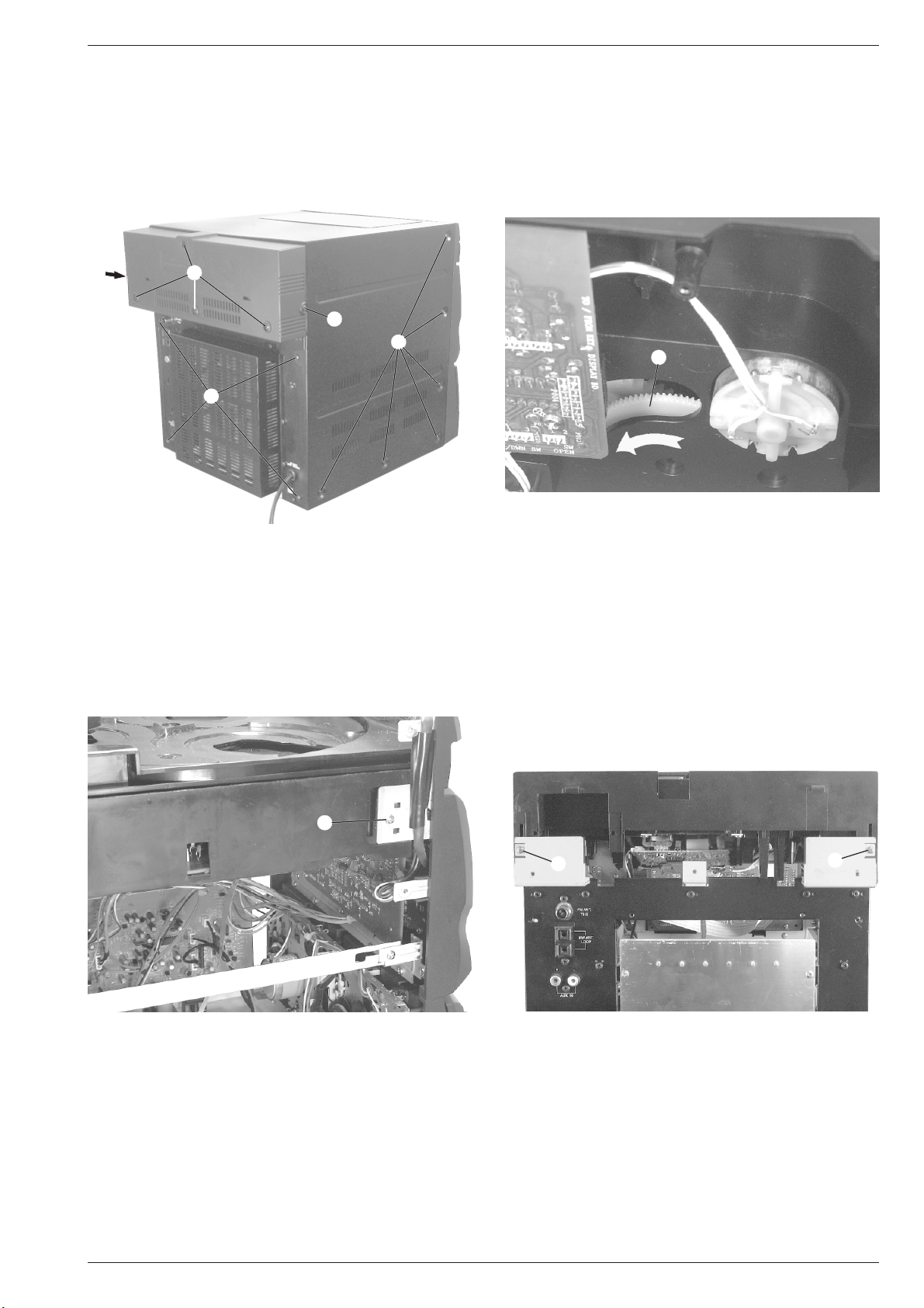
Ausbauhinweise
Gehäuse öffnen
- 6 Schrauben A (Fig. 1) der CD-Gehäuseabdeckung herausschrauben und Abdeckung abnehmen.
- Je 6 Schrauben B (Fig. 1) der Gehäuseseiten und 4 Schrauben C
(Fig. 1) herausschrauben und Blechabdeckung abnehmen.
A
Fig. 1
A
A
B
C
Disassembly Instructions
Opening the Cabinet
- Undo 6 screws A (Fig. 1) of the cover of the CD cabinet and remove
it.
- Undo 6 Schrauben B (Fig. 1) on each side of the sheet metal casing
and 4 screws C (Fig. 1) and remove the casing.
D
Fig. 2
1. CD-Teil ausbauen
- Durch Drehen des Zahnrades D (Fig. 2) in Pfeilrichtung die CDSchublade ausfahren und CD-Schubladenblende vorsichtig nach
oben abziehen.
- Leitungen zum CD-Teil lösen.
- Je 1 Schraube E (Fig. 3) links und rechts des CD-Teils, 2 Schrauben F (Fig. 4) herausschrauben und CD-Teil vorsichtig hinten
anheben und herausnehmen.
E
1. Dismantling the CD Unit
- Move the tray out by turning gearwheel D (Fig. 2) in the direction of
the arrow and pull out the CD tray cover carefully towards the top.
- Disconnect the leads to the CD Unit.
- Undo1 screw E (Fig. 3) each on the left and right of the CD Unit,
unscrew 2 screws F (Fig. 4), lift the CD Unit carefully on the rear
side and take it out.
F
F
Fig. 3
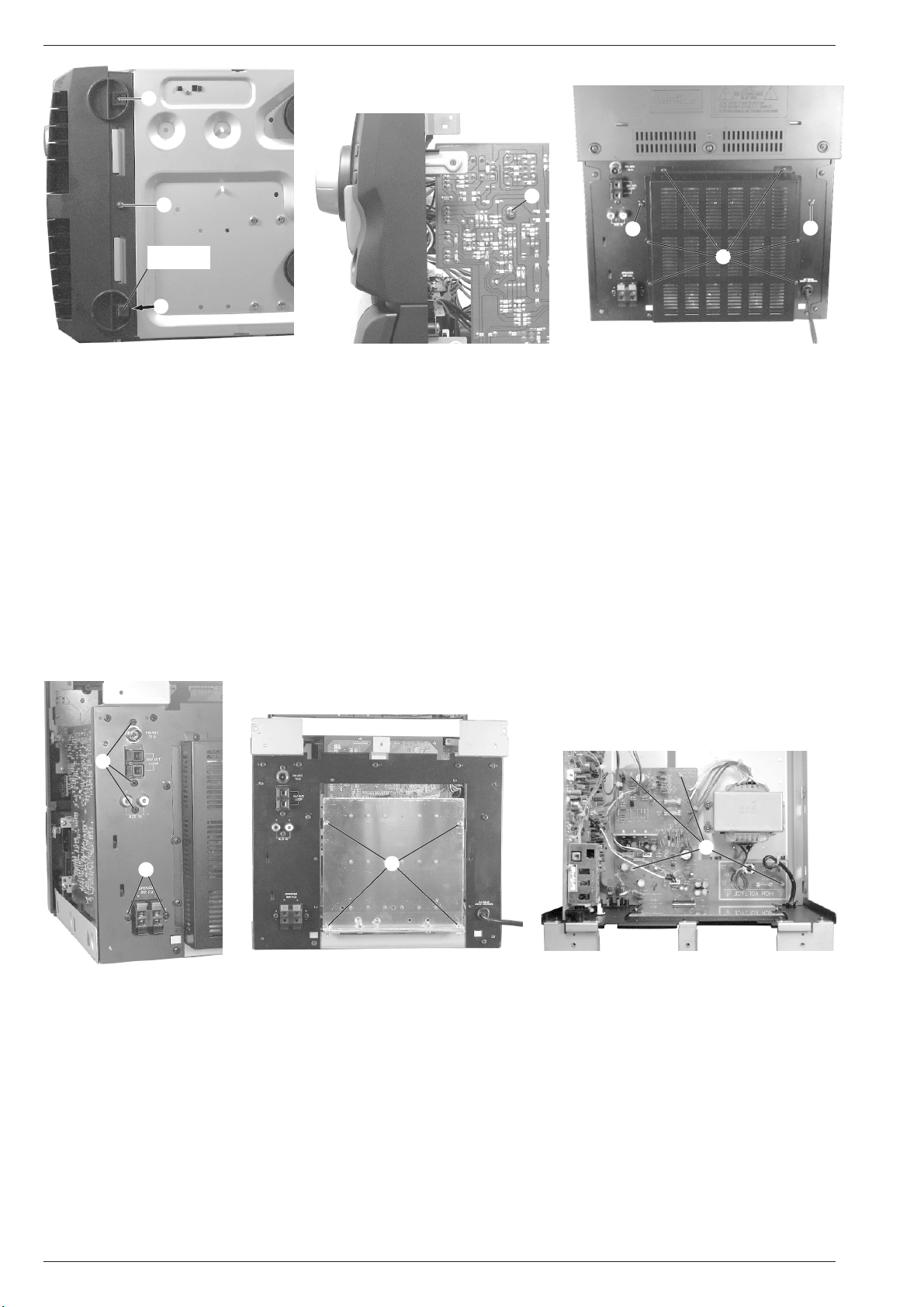
2. Frontblende ausbauen
- CD-Teil ausbauen (Punkt 1).
- Die aufgeklebten vorderen Gummifüße entfernen, die beiden
Schrauben G (Fig. 5) unter den Gummifüßen und die Schraube H
(Fig. 5) herausschrauben.
- Schraube I (Fig. 6), 2 Schrauben J (Fig. 7) herausschrauben und
Frontblende vorsichtig nach vorne abnehmen.
- Bei Bedarf Leitungen lösen.
GRUNDIG Service 1 - 11
Fig. 4
2. Dismantling the Front
- Dismantle the CD Unit (point 1).
- Remove the glued on rubber feet at the front, undo two screws G
(Fig. 5) below the rubber feet and screw H (Fig. 5).
- Undo screw I (Fig. 6), 2 screws J (Fig. 7) and remove the Front
carefully towards the front.
- Disconnect the leads if necessary.
Page 12
Allgemeiner Teil / General Section M 14
G
H
Gummifuß
Rubber Foot
G
Fig. 5 Fig. 6
3. Hauptplatte ausbauen
- Frontblende ausbauen (Punkt 2).
- 3 Schrauben K herausschrauben (Fig. 8).
- Bei Bedarf die Leitungen lösen.
- Hauptplatte nach vorne herausnehmen.
4. Power-Platte ausbauen
- Frontblende ausbauen (Punkt 2).
- Bei Bedarf die Leitungen lösen.
- Bei Bedarf Netztrafo ausbauen.
- 2 Schrauben L (Fig. 8) herausschrauben.
- 6 Schrauben M (Fig. 7) herausschrauben und Kühlblechabdeckung
abnehmen.
- 4 Schrauben N (Fig. 9) herausschrauben.
- 4 Rastnasen O (Fig. 10) ausrasten und Power-Platte herausnehmen.
I
J
J
M
Fig. 7
3. Removing the Main Circuit Board
- Remove the Front (point 2).
- Unscrew 3 screws K (Fig. 8).
- Disconnect the leads if necessary.
- Take out the Main Circuit Board towards the front.
4. Removing the Power Board
- Remove the Front (point 2).
- Disconnect the leads if necessary.
- Remove the mains transformer if necessary.
- Undo 2 screws L (Fig. 8).
- Undo 6 screws M (Fig. 7) and remove the heat sink cover.
- Undo 4 screws N (Fig. 9).
- Disengage the 4 catches O (Fig. 10) and take out the Power Board.
K
L
Fig. 8 Fig. 9 Fig. 10
5. Frontblende zerlegen
- Frontblende ausbauen (Punkt 2).
5.1 Steuerungsplatte ausbauen
- Bei Bedarf die Leitungen lösen.
- 5 Schrauben P herausschrauben (Fig. 11) und Steuerungsplatte
herausnehmen.
5.2 Tastenplatte ausbauen
- Bei Bedarf die Leitungen lösen.
- 8 Schrauben Q herausschrauben (Fig. 12) und Verbindungswinkel der beiden Frontblendenteile abnehmen.
- Je 3 Schrauben R (Fig. 13) der beiden Befestigungswinkel
herausschrauben und die Winkel aus den Führungen ziehen.
- 12 Schrauben S herausschrauben (Fig. 13) und Tastenplatte
herausnehmen.
N
5. Disassembling the Front
- Remove the Front (point 2).
5.1 Removing the Control Board
- Disconnect the leads if necessary.
- Undo 5 screws P (Fig. 11) and remove the Control Board.
5.2 Removing the Keybord PCB
- Disconnect the leads if necessary.
- Undo 8 screws Q (Fig. 12) and remove the connecting bracket of
the two parts of the front panel.
- Undo 3 screws R (Fig. 13) each of the two fastening brackets und
pull out the brackets from the guides.
- Undo 12 screws S (Fig. 13) and remove the Keyboard PCB.
O
1 - 12 GRUNDIG Service
Page 13

P
Allgemeiner Teil / General SectionM 14
Fig. 11
R
R
Fig. 13
5.3 CD-Tastenplatte ausbauen
- Je 3 Schrauben R (Fig. 13) der beiden Befestigungswinkel
herausschrauben und die Winkel aus den Führungen ziehen.
- 4 Schrauben T herausschrauben (Fig. 13) und CD-Tastenplatte
herausnehmen.
5.4 Cassetten-Laufwerk ausbauen
- Bei Bedarf die Leitungen lösen.
- Beide Cassetten-Türen öffnen.
- 6 Schrauben U (Fig. 14) herausschrauben und Cassetten-Laufwerk herausnehmen.
5.5 Cassetten-Laufwerktasten ausbauen
- Cassetten-Laufwerk ausbauen (Punkt 5.4).
- Je 2 Schrauben V (Fig. 15) der beiden Haltewinkel herausschrauben und Winkel herausnehmen.
- Die Cassetten-Laufwerktasten können herausgenommen werden.
S
T
S
R
R
Q
Fig. 12
U
Fig. 14
5.3 Removing the CD Keyboard PCB
- Undo 3 screws R (Fig. 13) of each of the two fastening brackets
and pull the brackets out of the guides.
- Undo 4 screws T (Fig. 13) and take out the CD Keyboard PCB.
5.4 Dismantling the Tape Deck
- Disconnect the leads if necessary.
- Open both cassette compartment doors.
- Undo 6 screws U (Fig. 14) and remove the Tape Deck.
5.5 Removing the Tape Deck Buttons
- Dismantle the tape deck (point 5.4).
- Undo 2 screws V (Fig. 15) of each of the two holding brackets and
remove the brackets.
- Remove the Tape Deck Buttons.
Q
U
U
X
V
W
V
W
X
Fig. 15
GRUNDIG Service 1 - 13
Y Y
Fig. 16 Fig. 17
Page 14

Allgemeiner Teil / General Section M 14
5.6 Cassetten-Türbremsen ausbauen
- Cassetten-Laufwerk ausbauen (Punkt 5.4).
- Je 2 Schrauben W (Fig. 15) der beiden Haltebleche herausschrauben und Cassetten-Türbremsen aus den Führungen ziehen.
5.7 Cassetten-Türblenden ausbauen
- Rastnasen X (Fig. 16, 17) ausrasten und Blende vorsichtig nach
oben schieben.
5.8 Cassetten-Türen ausbauen
- Cassetten-Laufwerk ausbauen (Punkt 5.4).
- Cassetten-Türblenden ausbauen (Punkt 5.7).
- Cassetten-Türfeder aushängen.
- Cassetten-Tür aus den Führungen Y (Fig. 15) ausrasten und Tür
vorsichtig nach hinten herausnehmen.
6. Cassetten-Motor ausbauen
- Cassetten-Laufwerk ausbauen (Punkt 5.4).
- Leitungen zum Cassetten-Motor ablöten.
- Die beiden Antriebsriemen aushängen.
- 2 Schrauben A (Fig. 18), 2 Schrauben B (Fig. 19) und 2 Schrauben
C (Fig. 20) herausschrauben, Cassetten-Motor mit Motorträger
abnehmen.
- 3 Motorschrauben D (Fig. 21) herausschrauben und CassettenMotor abnehmen.
5.6 Removing the Cassette Door Brakes
- Dismantle the Tape Deck (point 5.4).
- Undo 2 screws W (Fig. 15) of each of the two holding plates and
pull the Cassette Door Brakes out of the guides.
5.7 Removing the Cassette Door Covers
- Disengage the catches X (Fig. 16, 17) and push the Cover
carefully upwards to remove it.
5.8 Removing the Cassette Doors
- Dismantle the Tape Deck (point 5.4).
- Remove the Cassette Door Covers (point 5.7).
- Unhook the Cassette Door Spring.
- Disengage the Cassette Door from the guides Y (Fig. 15) and
remove the Door carefully towards the back.
6. Dismantling the Cassette Motor
- Dismantle the Tape Deck (point 5.4).
- Unsolder the leads to the Cassette Motor.
- Unhook the two driving belts.
- Undo 2 screws A (Fig. 18), 2 screws B (Fig. 19) and 2 screws C
(Fig. 20). Remove the Cassette Motor together with its support.
- Undo 3 motor screws D (Fig. 21) and remove the Cassette Motor.
A
Fig. 18 Fig. 19
C
Fig. 20 Fig. 21
7 CD-Teil zerlegen
- CD-Teil ausbauen (Punkt 1).
7.1 CD-Schublade ausbauen
- Das Zahnrad D (Fig. 22) so drehen, daß das CD-Laufwerk beim
Ausfahren der CD-Schublade in „Play“ Position bleibt.
- Die Leitung zur CD-Steuerplatte lösen.
- Die beiden Rastnasen E (Fig. 23) ausrasten und CD-Schublade
ganz herausziehen.
Achtung:
Vor dem Einsetzen der CD-Schublade muß das
Zahnrad F (Fig. 24) und das Steuerrad G (Fig. 24) in folgende
Position gebracht werden. Die Löcher å im Zahnrad F (Fig. 24)
und im Steuerrad G (Fig. 24) müssen über den Arretierungslöchern ∫ (Fig. 25) liegen.
7 Dismantling the CD Unit
- Dismantle the CD Unit (point 1).
7.1 Removing the CD Tray
- Turn the earwheel D (Fig. 22) so that the CD drive mechanism
remains in the „Play“ position when moving out the CD Tray.
- Detach the lead to the CD Control Board.
- Unlock the two catches E (Fig. 23) and pull out the CD Tray
completely.
Attention:
Before refitting the CD Tray, the gearwheel F (Fig. 24)
and control wheel G (Fig. 24) are to be positioned as follows: the
holes å in the gearwheel F (Fig. 24) and the control wheel G
(Fig. 24) must coincide with the locking holes ∫ (Fig. 25).
B
D
1 - 14 GRUNDIG Service
Page 15

Allgemeiner Teil / General SectionM 14
Fig. 22
O
D
J
G
å
F
I
Fig. 23
E
D
L
E
M
N
∂
H
K
∂
∫
Fig. 24 Fig. 25
7.2 Steuerrad G und Zahnräder F, H, D ausbauen
- CD-Schublade ausbauen (Punkt 7.1).
- Schraube I (Fig.24) herausschrauben und Zahnrad F (Fig. 24)
herausnehmen.
- Nach dem Entfernen des Zahnrades F Schraube J (Fig. 24)
herausschrauben und Steuerrad G (Fig. 24) herausnehmen.
- Nach dem Entfernen des Zahnrades F und des Steuerrades G
kann die Schraube K (Fig. 25) herausgeschraubt und das Zahnrad H (Fig. 25) herausgenommen werden.
- Zahnrad D (Fig. 25) kann nach dem Entfernen des Zahnrades F
und des Steuerrades G herausgenommen werden.
7.3 Steuerschieber M ausbauen
- CD-Schublade ausbauen (Punkt 7.1).
- Zahnrad F und Steuerrad G ausbauen (Punkt 7.2).
- Schraube L (Fig. 25) herausschrauben, Steuerschieber M
(Fig. 25) in Pfeilrichtung schieben, links anheben und vorsichtig
herausnehmen.
Achtung:
7.4 Motor O ausbauen
- CD-Schublade ausbauen (Punkt 7.1).
- Antriebsriemen abnehmen, 2 Schrauben P (Fig. 24) heraus-
7.5 Antriebsrad Q ausbauen
- CD-Schublade ausbauen (Punkt 7.1).
- Antriebsriemen abnehmen, Schraube R (Fig. 24) herausschrau-
7.6 CD-Laufwerk ausbauen
- 4 Schrauben S (Fig. 26) herausschrauben und das CD-Laufwerk
Beim Einsetzen des Steuerschiebers muß folgendes
beachtet werden: Die Führung ç (Fig. 26) des CD-Laufwerkrahmens muß in die Führungsrille des Steuerschiebers M
(Fig. 25) eingreifen. Der Schalterhebel N muß sich zwischen den
beiden Anschlägen ∂ (Fig. 25) befinden.
schrauben und den Motor O (Fig. 24) nach unten herausnehmen.
ben und Antriebsrad Q (Fig. 24) herausnehmen.
aus dem CD-Laufwerkrahmen herausnehmen.
P Q
R
7.2 Removing the Control Wheel G and Gearwheels F, H, D
- Dismantle the CD tray (point 7.1).
- Undo screw I (Fig. 24) and take out the Gearwheel F (Fig. 24).
- After having removed Gearwheel F undo screw J (Fig. 24) and
take out the Control Wheel G (Fig. 24).
- After having removed Gearwheel F and Control Wheel G screw
K (Fig. 25) can be unscrewed and Gearwheel H (Fig. 25) can be
taken out.
- Gearwheel D (Fig. 25) can be removed after having taken out
Gearwheel F and Control Wheel G.
7.3 Removing the Shifter M
- Dismantle the CD tray (point 7.1)
- Remove the gearwheel F and the control wheel G (point 7.2).
- Undo screw L (Fig. 25), move the Shifter M (Fig. 25) in the
direction of the arrow, lift it on the left and take it out carefully.
Attention:
(Fig. 26) on the frame of the CD drive mechanism must engage
with the groove of the Shifter M (Fig. 25). The switch lever N must
be positioned between the two limit stops ∂ (Fig. 25).
7.4 Removing the Motor O
- Dismantle the CD tray (point 7.1)
- Remove the driving belt, undo 2 screws P (Fig. 24) and take out
Motor O (Fig. 24) towards the bottom.
7.5 Driving Gear Q
- Dismantle the CD tray (point 7.1)
- Remove the driving belt, undo screw R (Fig. 24) and take out the
Driving Gear Q (Fig. 24).
7.6 Removing the CD Drive Mechanism
- Undo 4 screws S (Fig. 26) and take out the CD Drive Mechanism
from its frame.
Note the following when refitting the Shifter: Guide ç
GRUNDIG Service 1 - 15
Page 16

Allgemeiner Teil / General Section M 14
S
T
ç
Fig. 26
7.7 CD-Teller ausbauen
- Schraube T (Fig. 27) herausschrauben und CD-Teller abnehmen.
Achtung:
7.8 CD-Tellerantriebszahnrad V ausbauen
- CD-Teller ausbauen (Punkt 7.7).
- Schraube W (Fig. 28) herausschrauben und CD-Tellerantriebs-
7.9 Antriebswelle ausbauen
- Antriebsriemen abnehmen, Rastnase X (Fig. 29) ausrasten und
7.10 Motor Y ausbauen
- Antriebsriemen abnehmen, Haltebügel Z (Fig. 28) aushängen
Um die beiden Schalter U (Fig. 28) beim Einbau des CDTellers nicht zu beschädigen muß der CD-Teller um circa 20˚ nach
links versetzt zur Ausgangsposition aufgesetzt werden. Durch
Drehen am Motorpulley den CD-Teller in die Ausgangsposition
(wie in Fig. 27 abgebildet) zurückdrehen.
zahnrad V (Fig.28) herausnehmen.
Antriebswelle herausnehmen.
und den Motor Y (Fig. 28) aus der Halterung herausnehmen.
Y
Z
Fig. 27
7.7 Removing the CD Carriage
- Undo screw T (Fig. 27) and take out the CD Carriage.
Attention:
7.8 Removing the CD Carriage Driving Gearwheel V
- Remove the CD Carriage (point 7.7).
- Undo screw W (Fig. 28) and remove the CD Carriage Driving
7.9 Removing the Driving Shaft
- Remove the driving belt, unlock catch X (Fig. 29) and take out the
7.10 Removing the Motor Y
- Remove the driving belt, disengage the holding clip Z (Fig. 28)
To avoid damaging the two switches U (Fig. 28) when
fitting the CD Carriage, the CD Carriage is to be turned by about
20° from its home position when refitting it. Return the CD Carriage
to its home position (as shown in Fig. 27) by turning the motor
pulley.
Gearwheel V (Fig. 28).
Driving Shaft.
and take the Motor Y (Fig. 28) out of the holder.
X
V
U
W
Fig. 28
1 - 16 GRUNDIG Service
Fig. 29
Page 17

M 14 Abgleichvorschriften / Adjustment Procedures
D
Abgleichvorschriften
1. Tuner
Meßgeräte:
Meß-/Wobbelsender, Stereocoder, Oszilloskop, Klirrfaktormeßgerät, DC-Voltmeter, NF-Voltmeter
Servicearbeiten nach Austausch des Frontends: Abgleich Nr. 2
Das Frontend ist ein komplett abgeglichener Baustein. Nur das ZF-Filter muß dem ZF-Verstärker angeglichen werden.
Abgleich Vorbereitung Abgleichvorgang
1. FM-Oszillator
2. FM-ZF
3. FM-Demodulator
4. Stereo-Übersprechdämpfung
5. Nachbarkanalfilter
6. MW-Oszillator
7. AM-ZF
FM
DC-Voltmeter an Testpunkt TP18.
FM, 98MHz
Wobbler 98MHz an Antennenbuchse.
Pegel ca. 100µV/40dBµV/75Ω, f
Klirrfaktormeßgerät an Lautsprecheranschluß.
= 1kHz, Hub 22,5kHz.
mod
FM
Meßsender 98MHz an Antennenbuchse.
DC-Voltmeter an Testpunkt TP19 und TP20 anschließen.
FM, 98MHz
Stereocoder linker Kanal moduliert an Antennenbuchse.
98MHz, ± 6kHz Pilotton, Hub 40kHz.
NF-Voltmeter an Lautsprecheranschluß für rechten Kanal.
Gerät aus
Tongenerator 114kHz, 100mV über einen 40nF-Kondensator an IC601 (Pin 8) anschließen.
NF-Voltmeter über einen 40nF-Kondensator an IC601
(Pin 9) anschließen.
MW
DC-Voltmeter an Testpunkt TP18.
MW
Wobbler 450kHz an Antennenklemmen einspeisen.
Ua so klein wie nötig, m = 30%, f
NF-Voltmeter oder Oszilloskop an Lautsprecheranschluß.
= 1kHz.
mod
Bei 87,5MHz auf 1,6V ± 0,3V und 108,0MHz auf 7,5V ± 1V
kontrollieren.
Mit ZF-Filter (im Frontend) auf minimalen Klirrfaktor
einstellen.
Mit T604 auf 0V ± 0,02V zwischen den beiden Testpunkten
einstellen.
Mit VR601 auf Minimum einstellen.
Danach rechten Kanal modulieren und linken NF-Ausgang
kontrollieren
Mit T605 auf Minimum einstellen.
Mit T601 bei 522kHz auf 1,2V ± 0,2V einstellen.
Mit T603 auf Maximum einstellen.
8. MW-Vorkreis
MW
Meßsendersignal an Antennenklemmen einspeisen.
Ua so klein wie nötig, m = 30%, f
NF-Voltmeter oder Oszilloskop an Lautsprecheranschluß.
9. NF-Sperrkreise
FM, 98MHz
Meßsender an Antennenbuchse.
Pegel ca. 100µV/40dBµV/75Ω, f
NF-Voltmeter an Lautsprecheranschlüsse.
Beim Austausch eines der ZF-Filter achten Sie darauf, daß nur Filter mit gleicher
Kennfarbe bestückt sind.
ZF (MHz) ZF-Filter ZF-Filter
Kennbuchstabe Farbe
10,6500 D schwarz
10,6750 B blau
10,7000 A rot
10,7250 C orange
10,7500 E weiß
= 1kHz.
mod
= 19kHz.
mod
Mit L601 bei 558kHz auf Maximum einstellen.
Mit CT601 bei 1440kHz auf Maximum einstellen.
Abgleich wechselseitig wiederholen.
Mit T606 im rechten Kanal, bzw. mit T607 im linken
Kanal auf Minimum abgleichen.
GRUNDIG Service 2 - 1
Page 18

Abgleichvorschriften / Adjustment Procedures M 14
2. Cassettenteil
Meßgeräte/Meßmittel:
NF-Voltmeter, Frequenzzähler, z.B. Cr-Testkassette 448A
Abgleich Vorbereitung Abgleichvorgang
1. Azimut
2. Geschwindigkeit
3. Löschoszillator
Alignment Layout
Die Einstellschrauben der Tonköpfe sind durch kleine
Aussparungen in der Frontblende zugänglich.
Falls kein geeigneter Schraubendreher zur Verfügung
steht, können die Tonkopfschrauben durch Abnehmen der
Cassettenfachblenden (siehe Ausbau Punkt 5.7) besser
erreicht werden.
Cr-Testkassette 448A Pegeltonteil 10kHz wiedergeben.
NF-Voltmeter an Lautsprecherausgänge.
Deck A oder B:
Cr-Testkassette 448A einlegen und Pegeltonteil 3150Hz
wiedergeben.
Frequenzzähler an Lautsprecherausgänge.
Deck B: Leerkassette einlegen; Aufnahme.
Frequenzzähler an Testpunkt TP1 oder TP2.
Mit der Schraube A linken und rechten Kanal auf gleiches
Maximum einstellen.
A
Mit VR602 auf 3150Hz ± 60Hz einstellen.
Mit T608 auf 63kHz ± 1kHz einstellen.
AM
FM
AUX IN
ZF-Filter / IF Filter
Frontend
TP18
TP20
TP19
Pin 8
Pin 9
TP2
TP1
2 - 2 GRUNDIG Service
Page 19

M 14 Abgleichvorschriften / Adjustment Procedures
GB
Adjustment Procedures
1. Tuner
Measuring instruments:
Standard/sweep signal generator, stereo coder, oscilloscope, distortion meter, DC voltmeter, AF voltmeter
Service works after replacing the front end: Alignment no. 2
The front end is a completely adjusted module. Only the IF filter is to be tuned to the IF amplifier.
Alignment Preparation Procedure
1.FM Oscillator
2.FM IF
3.FM Demodulator
4.Stereo Crosstalk
5. Adjacent channel
filter
6.MW Oscillator
7. AM IF
FM
DC voltmeter to Testpoint TP18.
FM, 98MHz
Sweep generator 98MHz to aerial input.
Level about 100µV/40dBµV/75Ω, f
Distortion meter to Loudspeaker output.
= 1kHz, dev. 22.5kHz.
mod
FM
Signal generator 98MHz to aerial input.
Connect DC voltmeter between to Testpoint TP19 and
TP20.
FM, 98MHz
Stereo coder, left channel modulated to aerial input.
98MHz, ± 6kHz pilot, deviation 40kHz.
AF voltmeter to Loudspeaker output of right channel.
System off
Connect audio signal generator 114kHz, 100mV via a
40nF capacitor to IC601 (Pin 8).
Connect AF voltmeter via a 40nF capacitor to IC601 (Pin 9).
MW
DC voltmeter to Testpoint TP18.
MW
Sweep generator 450kHz to aerial inputs.
U
as low as possible, m = 30%, f
out
AF voltmeter or Oscilloscope to Loudspeaker output.
= 1kHz.
mod
Check at 87.5MHz for 1.6V ± 0.3V and at 108.0MHz for
7.5V ± 1V.
With IF Filter (inside of Frontend) set for minimum
distortion.
With T604 set for 0V ± 0.02V between both Testpoints.
With VR601 set for minimum.
Control the left AF output with modulated right channel.
With T605 set for minimum.
With T601set to 1.2V ± 0.2V at 522kHz.
With T603 set for maximum.
8.MW aerial
bandpass circuit
(MW RF)
9. AF reject circuits
MW
Signal generator to aerial input.
U
as low as possible, m = 30%, f
out
AF voltmeter or Oscilloscope to Loudspeaker output.
FM, 98MHz
Signal generator to aerial input.
Level about 100µV/40dBµV/75Ω, f
AF voltmeter to Loudspeaker outputs.
When replacing one of the ceramic
resonators, take care that the colour codes
of all resonators are the same.
IF (MHz) IF Filter IF Filter
Ident letter Colour
10.6500 D black
10.6750 B blue
10.7000 A red
10.7250 C orange
10.7500 E white
= 1kHz.
mod
= 19kHz.
mod
With L601 set for maximum at 558kHz.
With CT601 set for maximum at 1440kHz.
Repeat alignments alternately.
Align with T606 at the right channel, resp. with T607 at the
left channel for minimum.
GRUNDIG Service 2 - 3
Page 20

Abgleichvorschriften / Adjustment Procedures M 14
2. Tape Deck
Measuring instruments/Test equipment:
AF voltmeter, frequency counter, e.g. test cassette 448A
Alignment Preparation Procedure
1. Azimuth
2. Speed
3. Erase oscillator
frequency
Alignment Layout
Access to the adjustment screws of the audio heads is
possible through small cutouts on the front panel.
If there is no suitable screwdriver available, access to the
audio head screws is better by removing the cassette
compartment covers (see point 5.7 of the disassembly
instructions).
Play back the 10kHz pilot sound section on the Cr test
cassette 448A.
AF voltmeter to Loudspeaker outputs.
Deck A or B:
Load Cr test cassette 448A and play back the 3150Hz
sound section.
Frequency counter to Loudspeaker outputs.
Deck B: Insert empty cassette, Record.
Frequency counter to Testpoint TP1 or TP2.
With screw A set the left and right channel for same
maximum.
A
With VR602 adjust for 3150Hz ± 60Hz.
With T608 adjust for 63kHz ± 1kHz.
AM
FM
AUX IN
ZF-Filter / IF Filter
Frontend
TP18
TP20
TP19
Pin 8
Pin 9
TP2
TP1
2 - 4 GRUNDIG Service
Page 21

Platinenabbildungen und Schaltpläne / Layout of PCBs and Circuit DiagramsM 14
Platinenabbildungen und Schaltpläne / Layout of PCBs and Circuit Diagrams
Blockschaltplan / Block Diagram
GRUNDIG Service 3 - 1
Page 22

Platinenabbildungen und Schaltpläne / Layout of PCBs and Circuit Diagrams M 14
Schaltplan – Tuner-Teil / Circuit Diagram – Tuner Part
8
AM-HF
AM-ZF / AM IF
FM-HF
FM-ZF / FM IF
NF rechts / AF right
NF links / AF left
9
8
FE601
9
3 - 2 GRUNDIG Service
Page 23

Platinenabbildungen und Schaltpläne / Layout of PCBs and Circuit Diagrams Platinenabbildungen und Schaltpläne / Layout of PCBs and Circuit DiagramsM 14 M 14
REVERENCE
DIVIDER
SWALLOW COUNTER
1/16, 1/17 4bits
12 bits PROGRAMMABLE
DIVIDER
1/2
DAT A SHIFT REGISTER
LATCH
CCB
I/F
21
17
6
5
4
3
15
16
22
1
VSS
VDO
DO
CL
DI
CE
AM IN
FM IN
XOUT
XIN 10
19
20
1212
PO
A IN
A OUT
IF IN
131110987
IO2IO1BO4BO3BO2BO1
LC 72131M
POWER ON
RESET
UNIVERSAL
COUNTER
UNLOCK
DETECTOR
PHASE DETECTOR
CHARGE PUMP
#@
TO CN108
CONTROL BOARD
PAGE 3 - 11
0
0
!
IC601 LA1851A
MIX. OUT
26
AM MIX
AM RF
27
!
AM IF IN
FM IF IN
24 1 2 3
AM OSC
FM IF
FM IF
FM LEVEL
DET
VCC
FM DISC
AM DET OUT
AM DET IN
FM DET OUT
FM DET IN
PILOT
PILOT
DET
PD
PLL FILTER
75689 1011 132221
FM DET
AGC
COMP
VCO
TRIG
VCO FF 38KHz
LED
DRIVE
ST LED
TU LED
FF 19KHz
FF 19KHz
TO CN113
CONTROL BOARD
PAGE 3 - 11
TO CN803
POWER BOARD
PAGE 3 - 17
TO MAIN BOARD
IC603 LC72131
0°
90°
28
VR EQ
@ #
GRUNDIG Service GRUNDIG Service
V REG
LA 1851N
ALC
AM OSC
3029
SD ADJ
BU OUT/
AM IF
OUT
FM AFC
ADJ
AM SO
AM DET
AGC/
IF BUFF
METER
MUTE
TU/ST
AM/FM
AM/FM
IF COUNT
RESET
3 - 3 3 - 4
(6dB)
AM MUTE
DECODER ST SW
R OUT
SEP
L OUT
231215141720181925164
GND
Page 24

Platinenabbildungen und Schaltpläne / Layout of PCBs and Circuit Diagrams Platinenabbildungen und Schaltpläne / Layout of PCBs and Circuit Diagrams M 14M 14
PIN 1 9.01V
PIN 2 0V
PIN 3 11.86V
PIN 1 0V
PIN 2 0V
PIN 3 1.26V
PIN 4 1.31V
PIN 5 1.35V
PIN 6 1.31V
PIN 7 0V
PIN 8 0V
PIN 9 1.87V
PIN10 1.27V
PIN 11 0V
PIN 12 0V
PIN 13 0.82V
PIN 14 0V
PIN 15 1.26V
PIN 16 1.87V
PIN 17 1.43V
PIN 18 8.00V
PIN 19 7.63V
PIN 20 1.34V
PIN 21 1.30V
PIN 22 1.26V
PIN 23 0V
PIN 24 0V
Platinenabbildungen / Layout of PCBs:
Ansicht von der Bestückungsseite / View of component side
Hauptplatte / Main Board
Für die tatsächliche Bauteilbestückung ist das Schaltbild maßgebend!
The circuit diagram is relevant for the actual component assembly!
8 9 @ # 0 ! !0
IC 602
NJM78L09
IC601
LA1851N
PIN 1 2.08V 2.28V 2.48V 2.35V
PIN 2 2.08V 2.28V 0.03V 0.03V
PIN 3 8.20V 8.20V 0.04V 0.04V
PIN 4 2.30V 2.23V 0.05V 0.05V
PIN 5 0V 0.57V 4.80V 4.8V
PIN 6 2.18V 2.15V 4.89V 4.88V
PIN 7 8.20V 8.20V 0.21V 11.28V
PIN 8 3.60V 2.27V 7.52V 0V
PIN 9 2.18V 2.16V 8.80V 0.15V
PIN10 6.72V 7.59V 0V 0V
PIN 11 6.72V 7.76V 0.10V 0.10V
PIN 12 0.53V 0.53V 0V 0V
PIN 13 6.50V 5.89V 0V 0V
PIN 14 2.50V 2.50V 0V 0V
PIN 15 2.54V 2.55V 0V 2.25V
PIN 16 1.49V 1.43V 2.57V 0V
PIN 17 0V 0V 5.59V 5.60V
PIN 18 8.32V 0.77V 1.07V 1.09V
PIN 19 0.11V 0.12V 1.07V 1.09V
PIN 20 0.81V 0.74V 1.55V 1.18V
PIN 21 8.18V 8.15V 0V 0V
PIN 22 7.93V 7.92V 2.81V 2.81V
PIN 23 0V 0V
PIN 24 2.07V 2.28V
PIN 25 0.05V 0.58V
PIN 26 8.19V 8.18V
PIN 27 0V 2.23V
PIN 28 2.30V 2.24V
PIN 29 1.62V 2.21V
PIN 30 0.60V 0.75V
FM AM FM AM
IC603
LC72131
IC605
TA8189N
Kopfhörerplatte / Headphone Board
VON VORNE
FRONT VIEW
2SD2012
BCE
VON UNTEN
BOTTOM VIEW
BESCHRIFTUNG
INSCRIPTION
ECB
VON UNTEN
BOTTOM VIEW
BCE
DTC114ES
2SA1317U
2SC3330U
2SC2999D
2SD1936T
2SB926
8050C
456 56 4 7
IC 604
UPC1330HA
PIN 1 0V 0.52V
PIN 2 0V 0V
PIN 3 0V 0V
PIN 4 0.02V 0.52V
PIN 5 0V 0V
PIN 6 7.94V 5.35V
PIN 7 0V 11.79V
PIN 8 0V 5.34V
PIN 9 0V
IC 607
TDA2822M
TRANSISTOR
Ref. No. E B C
Q610 0V 0V 5.18V 2SC3330
Q611 1.59V 10.83V 11.51V 2SA1317
Q612 1.40V 2.10V 7.25V 2SC2999D
Q613 1.80V 2.30V 1.62V 2SA1317
Q615 2.30V 1.79V 0V 2SA1317
Q619 8.19V 7.67V 6.69V 2SA1317
Q620 8.82V 8.15V 8.81V 2SA1317
Q621 0V 0.64V 0V 2SC3330
Q622 9.02V 8.22V 8.82V 2SA1317
TRANSISTOR
Ref. No. E B C
Q623 4.42V 3.95V 7.95V 2SC3330
Q625 0.39V 0.48V 5.20V 2SD1936T
Q626 9.20V 8.41V 9.08V 2SA1317
Q627 0V 0.67V 0V 2SC3330
Q628 0V 0.71V 0V 2SC3330
Q629 0V 0.69V 0V 2SC3330
Q630 9.32V 8.49V 9.19V 2SA1317
Q631 7.25V 7.94V 7.96V 2SA1317
Q632 11.11V 11.81V 11.89V 8050D
Q633 11.15V 11.89V 11.88V 2SA1317
Q634 0V 0.67V 0V 2SC3330
Q635 0V 0.60V 0V 2SC3330
Q636 0V 0.66V 0V 2SC3330
Q637 7.26V 8.70V 9.27V 2SA1317
Q638 0V 0.69V 0V 2SC3330
Q639 11.38V 10.00V 9.31V 8050D
Q640 0V 0.67V 0V 2SC3330
Q641 0V 0.67V 0V 2SC3330
Q642 0V 0.61V 0V 2SC3330
Q643 0V 0.61V 0V 2SC3330
Q646 4.05V 3.50V 8.10V 2SC3330
Q647 4.30V 3.62V 8.10V 2SC3330
Q648 0V 0.67V 0V 2SD1936T
Q649 0V 0.67V 0V 2SD1936T
Q650 2V 2.25V 5.30V 2SC3330
Q651 1.90V 2.18V 5.45V 2SC3330
Q652 0V 0.67V 0V 2SD1936T
Q653 0V 0.67V 0V 2SD1936T
Q654 0V 0.67V 0V 2SC3330
Q655 0V 0.67V 0V 2SC3330
IC 606
LC 75396E
PIN 1 3.59V PIN 33 3.36V
PIN 2 3.64V PIN 34 3.63V
PIN 3 2.93V PIN 35 3.59V
PIN 4 2.10V PIN 36 2.29V
PIN 5 3.63V PIN 37 3.63V
PIN 6 2.92V PIN 38 2.08V
PIN 7 3.28V PIN 39 2.93V
PIN 8 3.64V PIN 40 3.64V
PIN 9 2.93V PIN 41 3.28V
PIN10 2.08V PIN 42 2.93V
PIN 11 3.63V PIN 43 3.63V
PIN 12 2.92V PIN 44 2.09V
PIN 13 3.60V PIN 45 2.29V
PIN 14 3.64V PIN 46 3.36V
PIN 15 3.35V PIN 47 3.60V
PIN 16 3.36V PIN 48 3.35V
PIN 17 3.64V PIN 49 3.36V
PIN 18 3.36V PIN 50 3.36V
PIN 19 3.56V PIN 51 3.44V
PIN 20 3.64V PIN 52 3.43V
PIN 21 3.64V PIN 53 3.43V
PIN 22 3.61V PIN 54 3.43V
PIN 23 4.77V PIN 55 3.43V
PIN 24 5.24V PIN 56 7.31V
PIN 25 0V PIN 57 3.43V
PIN 26 0V PIN 58 3.43V
PIN 27 3.64V PIN 59 3.43V
PIN 28 3.64V PIN 60 3.43V
PIN 29 3.56V PIN 61 3.43V
PIN 30 3.36V PIN 62 3.63V
PIN 31 3.64V PIN 63 3.63V
PIN 32 3.56V PIN 64 3.35V
3 - 5 3 - 6
GRUNDIG Service GRUNDIG Service
Page 25

Platinenabbildungen und Schaltpläne / Layout of PCBs and Circuit Diagrams Platinenabbildungen und Schaltpläne / Layout of PCBs and Circuit DiagramsM 14 M 14
7
P
Schaltplan – Hauptplatte, Kopfhörerplatte / Circuit Diagram – Main Board, Headphone Board
TO TUNER PART
TO BC01
CD BOARD
PAGE 3 - 24
AUX IN
4 5
6
TO CN10
CONTROL BOARD
7
NF rechts "Aufnahme" Cass.
AF right "Record" Cass.
NF links "Aufnahme" Cass.
AF left "Record" Cass.
NF rechts und NF rechts "Wiedergabe" Cass.
AF right and NF right "Play" Cass.
NF links und NF links "Wiedergabe" Cass.
AF left and NF left "Play" Cass.
GRUNDIG Service GRUNDIG Service
3 - 7 3 - 8
Page 26

Platinenabbildungen und Schaltpläne / Layout of PCBs and Circuit Diagrams Platinenabbildungen und Schaltpläne / Layout of PCBs and Circuit Diagrams M 14M 14
TO CN116
CONTROL BOARD
PAGE 3 - 12
IC606 LC75396E
4
5
TO CN107
L BOARD PAGE 3 - 11
TO CASS DRIVE
MECHANISM
HEADPHONE BOARD
J736
J738
J735
TO CN801
POWER
J737
BOARD
PAGE 3 - 17
TO CN110
CONTROL BOARD
PAGE 3 - 11
6
7
IC607 TDA2822M
IC605 TA8189
TA 8189 N
CH2/B
23
24
CH2/A
*
CH1/A
1
CH1/B
2
Metal
NF
Out
–
ch 2
+
+
ch 1
–
Tape A
Pre
Tape B
Out NF
A / B
1
1
ref
ref
I
V
M / N
Rec
OutCGVCC
1516171819202122
–
ch 2
ch 1
+
ALC
+
–
2
ref
V
Rec IN
14
ALC
13
GND
12
Rec IN
11
TO CASS DRIVE
MECHANISM
3 - 9 3 - 10
GRUNDIG Service GRUNDIG Service
345678910
NF Metal
Out
IC604 UPC1330
Pre
Out
MIX
Out
GND 1
M/N
Rec
Out
NF
Page 27

Platinenabbildungen und Schaltpläne / Layout of PCBs and Circuit Diagrams Platinenabbildungen und Schaltpläne / Layout of PCBs and Circuit DiagramsM 14 M 14
$
Schaltplan – Steuerplatte, LED-Platte / Circuit Diagram – Control Board, LED Board
TO CN611
MAIN BOARD
PAGE 3 - 9
%
%
$
TO CN101
KEY BOARD
PAGE 3 - 15
TO CN104
KEY BOARD
PAGE 3 - 15
TO CN619
MAIN BOARD
PAGE 3 - 9
TO CN601
MAIN BOARD
TO CN804
POWER BOARD
PAGE 3 - 17
TO CN608
MAIN BOARD
PAGE 3 - 9
PAGE 3 - 4
TO CN805
POWER BOARD
PAGE 3 - 17
GRUNDIG Service GRUNDIG Service
TO CN105
KEY BOARD
PAGE 3 - 15
TO P004
CD MOTOR
CONTROL BOARD
PAGE 3 - 22
TO CN106
KEY BOARD
PAGE 3 - 16
TO CN602
TUNER BOARD
PAGE 3 - 4
3 - 11 3 - 12
TO BC01
CD BOARD
PAGE 3 - 24
TO CN804
POWER BOARD
PAGE 3 - 17
LED BOARD
Page 28

Platinenabbildungen und Schaltpläne / Layout of PCBs and Circuit Diagrams Platinenabbildungen und Schaltpläne / Layout of PCBs and Circuit Diagrams M 14M 14
Platinenabbildungen / Layout of PCBs:
Ansicht von der Bestückungsseite / View of component side
LED-Platte / LED Board
Steuerplatte / Control Board
IC101 UPD753016
%$
VON VORNE
FRONT VIEW
2SD2012
BCE
VON UNTEN
BOTTOM VIEW
BESCHRIFTUNG
INSCRIPTION
ECB
DTC114ES
2SA1317U
2SC3330U
2SC2999D
VON UNTEN
BOTTOM VIEW
2SD1936T
2SB926
BCE
8050C
TRANSISTOR
Ref. No. E B C
Q101 5.56V 5.52V 1.15V 2SA1317
Q102 0V 0.60V 0V 2SC3330
Q103 4.86V 0V 0V 2SC3330
Q104 0V 0V 5.31V DTC114ES
Für die tatsächliche Bauteilbestückung ist das Schaltbild maßgebend!
The circuit diagram is relevant for the actual component assembly!
Q106
PST529D
PIN 1 5.43V
PIN 2 0V
PIN 3 5.56V
IC 102
MC14094B
PIN 1 5.56V
PIN 2 0V
PIN 3 4.73V
PIN 4 5.54V
PIN 5 5.54V
PIN 6 5.54V
PIN 7 5.54V
PIN 8 0V
PIN 9 5.54V
PIN10 5.54V
PIN 11 5.54V
PIN 12 5.54V
PIN 13 5.54V
PIN 14 5.54V
PIN 15 5.54V
PIN 16 5.54V
IC 101
UPD753016-E62
PIN 1 2.40V PIN 41 1.63V
PIN 2 2.40V PIN 42 4.29V
PIN 3 2.40V PIN 43 0.31V
PIN 4 2.40V PIN 44 5.10V
PIN 5 2.40V PIN 45 5.38V
PIN 6 2.40V PIN 46 4.72V
PIN 7 2.40V PIN 47 2.21V
PIN 8 2.40V PIN 48 4.89V
PIN 9 2.40V PIN 49 0V
PIN10 2.40V PIN 50 0.30V
PIN 11 2.40V PIN 51 4.90V
PIN 12 2.40V PIN 52 5.38V
PIN 13 2.40V PIN 53 5.38V
PIN 14 2.40V PIN 54 4.90V
PIN 15 2.40V PIN 55 5.20V
PIN 16 2.40V PIN 56 0V
PIN 17 0V PIN 57 4.90V
PIN 18 0V PIN 58 1.38V
PIN 19 4.85V PIN 59 3.26V
PIN 20 4.85V PIN 60 5.37V
PIN 21 2.42V PIN 61 4.27V
PIN 22 2.42V PIN 62 0.80V
PIN 23 2.42V PIN 63 4.90V
PIN 24 2.42V PIN 64 5.30V
PIN 25 4.89V PIN 65 5.30V
PIN 26 4.89V PIN 66 5.30V
PIN 27 3.22V PIN 67 5.30V
PIN 28 1.61V PIN 68 5.20V
PIN 29 5.45V PIN 69 2.40V
PIN 30 5.45V PIN 70 2.40V
PIN 31 5.45V PIN 71 2.40V
PIN 32 5.45V PIN 72 2.40V
PIN 33 0V PIN 73 2.40V
PIN 34 0V PIN 74 2.40V
PIN 35 5.50V PIN 75 2.40V
PIN 36 5.50V PIN 76 2.40V
PIN 37 5.50V PIN 77 2.40V
PIN 38 0.51V PIN 78 2.40V
PIN 39 4.89V PIN 79 2.40V
PIN 40 5.37V PIN 80 2.40V
IC102 TC4094BP
3 - 13 3 - 14
GRUNDIG Service GRUNDIG Service
Page 29

Platinenabbildungen und Schaltpläne / Layout of PCBs and Circuit Diagrams Platinenabbildungen und Schaltpläne / Layout of PCBs and Circuit DiagramsM 14 M 14
TO SEN
CONTROL BOARD
PAGE 3 - 11
TO CN112
CONTROL BOARD
PAGE 3 - 11
TO CN117
CONTROL BOARD
PAGE 3 - 12
TO CN118
CONTROL BOARD
PAGE 3 - 12
CD KEY BOARD
Tastenplatte / Key Board
Ansicht von der Bestückungsseite / View of component side
Schaltplan – Tastenplatte, CD-Tastenplatte / Circuit Diagram – Key Board, CD Key Board
CD-Tastenplatte / CD Key Board
Ansicht von der Bestückungsseite / View of component side
Für die tatsächliche Bauteilbestückung ist das Schaltbild maßgebend!
The circuit diagram is relevant for the actual component assembly!
GRUNDIG Service GRUNDIG Service
3 - 15 3 - 16
Page 30

Platinenabbildungen und Schaltpläne / Layout of PCBs and Circuit Diagrams Platinenabbildungen und Schaltpläne / Layout of PCBs and Circuit Diagrams M 14M 14
Schaltplan – Leistungsplatte / Circuit Diagram – Power Board
NF rechts / AF right
NF links / AF left
TO J737
MAIN BOARD
PAGE 3 - 9
TO J735
MAIN BOARD
PAGE 3 - 9
CONTROL BOARD
TO CN114
CONTROL BOARD
PAGE 3 - 12
TO CN106
CONTROL BOARD
PAGE 3 - 11
CONTROL BOARD
TO P006
CD MOTOR
PAGE 3 - 22
TO CN603
MAIN BOARD
PAGE 3 - 4
TO CN109
PAGE 3 - 11
3 - 17 3 - 18
GRUNDIG Service GRUNDIG Service
Page 31

Platinenabbildung / Layout of PCB:
Ansicht von der Bestückungsseite / View of component side
Leistungsplatte / Power Board
Platinenabbildungen und Schaltpläne / Layout of PCBs and Circuit Diagrams Platinenabbildungen und Schaltpläne / Layout of PCBs and Circuit DiagramsM 14 M 14
TRANSISTOR
Ref. No E B C
Q801 11.80V 12.50V 16.30V 2SD2021
Q802 9.16V 9.43V 16.30V 2SD2021
Q803 0V 0.65V 0V 2SC3330
Q804 9.38V 9.97V 16.45V 2SC3330
Q805 12.50V 13.08V 16.30V 2SC3330
Q806 16.30V 15.56V 16.20V 2SA1317
Q807 16.30V 15.56V 16.20V 2DB926
Q808 0V 0.61V 0V 2SC3330
Q811 0V 0.67V 0V 2SD1936T
Q812 0V 0.67V 0V 2SD1936T
IC 801
LA4282
PIN 1 1.12V
PIN 2 0.06V
PIN 3 17.35V
PIN 4 0V
PIN 5 0.66V
PIN 6 1.12V
PIN 7 17.35V
PIN 8 0V
PIN 9 0V
PIN10 35.70V
PIN 11 17.35V
PIN 12 0V
Für die tatsächliche Bauteilbestückung ist das Schaltbild maßgebend!
The circuit diagram is relevant for the actual component assembly!
VON VORNE
FRONT VIEW
2SD2012
BCE
IC 802
NJM7809
PIN 1 8.92V 5.50V
PIN 2 0V 0V
PIN 3 16.30V 16.30V
VON UNTEN
BOTTOM VIEW
BESCHRIFTUNG
INSCRIPTION
ECB
DTC114ES
2SA1317U
2SC3330U
2SC2999D
IC 803
NJM78L05
VON UNTEN
BOTTOM VIEW
2SD1936T
2SB926
8050C
BCE
GRUNDIG Service GRUNDIG Service
3 - 19 3 - 20
Page 32

Platinenabbildungen und Schaltpläne / Layout of PCBs and Circuit Diagrams Platinenabbildungen und Schaltpläne / Layout of PCBs and Circuit Diagrams M 14M 14
Schaltplan – CD-Motor-Steuerplatte / Circuit Diagram – CD Motor Control Board
IC009 AN6651
IC008 LB1641
IC 008
LB1641
PIN 1 0V 11.84V
PIN 2 0.58V 11.84V
PIN 3 0.73V 11.72V
PIN 4 0.21V 11.84V
PIN 5 1.86V
PIN 6 1.86V
PIN 7 11.82V
PIN 8 11.82V
PIN 9 0.75V
PIN10 0.57V
IC 009
AN6651
TRANSISTOR
Ref. No. E B C
Q010 0V 0.74V 0V C2236
VON VORNE
FRONT VIEW
2SD2012
BCE
VON UNTEN
BOTTOM VIEW
BESCHRIFTUNG
INSCRIPTION
ECB
DTC114ES
2SA1317U
2SC3330U
2SC2999D
TO CN111
CONTROL BOARD
PAGE 3 - 11
+12V
TO CN802
POWER BOARD
PAGE 3 - 17
VON UNTEN
BOTTOM VIEW
2SD1936T
2SB926
8050C
BCE
3 - 21 3 - 22
GRUNDIG Service GRUNDIG Service
Page 33

1
2
3
Schaltplan – CD-Platte / Circuit Diagram – CD Board
Digital
NF rechts / AF right
NF links / AF left
Platinenabbildungen und Schaltpläne / Layout of PCBs and Circuit Diagrams Platinenabbildungen und Schaltpläne / Layout of PCBs and Circuit DiagramsM 14 M 14
3
1
CONTROL BOARD
GRUNDIG Service GRUNDIG Service
3 - 23 3 - 24
TO CN113
PAGE 3 - 12
TO CN604
MAIN BOARD
PAGE 3 - 7
2
Page 34

Platinenabbildungen und Schaltpläne / Layout of PCBs and Circuit Diagrams Platinenabbildungen und Schaltpläne / Layout of PCBs and Circuit Diagrams M 14M 14
PIN
1
2
3
4
5
6
7
8
9
10
11
12
13
14
15
16
17
18
19
20
21
22
23
24
25
COM1
COM1
AM
HI-SPEED
CLASSIC
JAZZ
POP
ROCK
6F
6A
6D
5F
5A
5D
4F
4A
3F
3A
2F
2A
1F
1A
MHz
COM2
COM2
PM
TIME
PLAY
UBS
ALL
DISC2
6I
6B
TIMER
5H,5I
5B
TRACK
4G
4B
3G
3B
2G
2B
1G
1B
KHz
COM3
COM3
FM
MUTE
PAUSE
REPEAT
DISC
DISC1
6G
6C
ON
5G
5C
STEREO
4E
4C
3E
3C
2E
2C
1E
1C
INTRO
COM4
COM4
LW
SLEEP
/
1
MW
DISC3
6E
6K
OFF
5E
5K,5J
´´I´´
4D
MEMO
3D
COLON
2D
POINT
1D
PROG
RAND
Display
IC 01
ST7CD1Q1J
PIN 1 3.4V
PIN 6 0V
PIN 7 3.4V
PIN 9 0V
PIN10 3.4V
PIN 11 3.4V
PIN 12 3.4V
PIN 13 3.4V
PIN 15 3.4V
PIN 16 3.4V
PIN 21 1.1V
PIN 22 1.7V
PIN 23 1.7V
PIN 24 1.8V
PIN 25 5.2V
PIN 26 3.4V
PIN 28 1.7V
PIN 30 1.7V
PIN 31 0V
PIN 32 0V
PIN 35 0V
PIN 38 5V
PIN 44 3.4V
PIN 47 1.1V
PIN 48 1.2V
PIN 49 2.5V
PIN 50 0.2V
PIN 51 0.2V
PIN 52 0V
IM 01
TDA7073A
PIN 1 1.7V 1.7V
PIN 2 1.7V 1.7V
PIN 5 5V 5V
PIN 6 1.7V 1.7V
PIN 7 1.7V 1.7V
PIN 9 2.4V 2.4V
PIN 10 0V 0V
PIN 12 2.5V 2.5V
PIN 13 2V 2.5V
PIN 14 0V 0V
PIN 16 2.8V 2.4V
TRANSISTOR
Ref. No. E B C
TA01 3.2V 2.5V 1.8V BC858B
TP01 3.4V 4.1V 5V BC338-25
TP02 0V 0V 4.1V BC848B
TP03 5V 4.5V 0V BC858B
VON VORNE
FRONT VIEW
BCE
TDA7073A
2SD2012
IM 02
VON UNTEN
BOTTOM VIEW
BESCHRIFTUNG
INSCRIPTION
ECB
IN 01
TDA1310TA
PIN 1 1.7V 2.4V
PIN 2 1.7V 2.2V
PIN 3 2.2V
PIN 4 0V 0V
PIN 5 2.2V 2.2V
PIN 6 2.2V 2.2V
PIN 7 0.5V 2.4V
PIN 8 2.2V 4.9V
PIN 1 8.9V
PIN 2 0V
PIN 3 5V
VON UNTEN
BOTTOM VIEW
DTC114ES
2SA1317U
2SC3330U
2SC2999D
BCE
IN 02
MC4558CD
IP 01
MC7805-CT
2SD1936T
2SB926
8050C
IM01, IM02 TDA7073A
16
14
13
3 - 25 3 - 26
12
10
9
TDA7073A
+
+
VDD
+
+
+
-
1
2
5
+
6
7
GRUNDIG Service GRUNDIG Service
Page 35

Verdrahtungsplan / Wiring Diagram
Platinenabbildungen und Schaltpläne / Layout of PCBs and Circuit Diagrams Platinenabbildungen und Schaltpläne / Layout of PCBs and Circuit DiagramsM 14 M 14
3
5
2
2
KOPFHÖRERPLATTE
HEADPHONE BOARD
TRAFO
HAUPTPLATTE
MAIN BOARD
5
4
LEISTUNGSPLATTE
MOTORSWITCH
POWER BOARD
TAPE A
CS-21ZSW-1415
44 3 2 4
CD-TASTENPLATTE
TAPE B
CD-LAUFWERK
3 2 3
2
CD DRIVE
MECHANISM
3 6
3 55
CD KEY BOARD
8
1
4
CD-MOTORSTEUERPLATTE
CD MOTOR
CONTROL BOARD
CD-MOTOR
CAROUSEL MECHANISM
M
MOTOR
DRAWER
TASTENPLATTE
KEY BOARD
STEUERPLATTE
CONTROL BOARD
GRUNDIG Service GRUNDIG Service
3 - 27 3 - 28
P024 P006
P020 P026
IC009IC009
P004
IC008
P022 P023
SWITCH
DOWN/UP
SC02 SC01
LED-Platte / LED BOARD
3
Page 36

Explosionszeichnungen und Ersatzteillisten / Exploded Views and Spare Parts Lists Explosionszeichnungen und Ersatzteillisten / Exploded Views and Spare Parts Lists M 14M 14
14
12
15
80
1
3
44
43
46
27
2
5
7
10
4
6
9
8
9
13
11
11
14
12
45
47
48
51
53
52
59
58
49
56
50
54
55
62
60
61
57
64
67
70
68
85
84
83
82
83
82
26
29
81
21
13
17
18
16
20
19
22
23
24
25
26
30
28
31
72
65
63
66
71
69
35
36
32
34
86
92
91
88
87
93
33
37
38
39
40
75
74
76
77
78
79
73
41
90
96
89
94
95
99
42
98
97
100
101
Explosionszeichnungen und Ersatzteillisten / Exploded Views and Spare Parts Lists
Explosionszeichnung – M 14 / Exploded View – M 14
1
4 - 1 4 - 2
GRUNDIG Service GRUNDIG Service
Page 37

M 14 Explosionszeichnungen und Ersatzteillisten / Exploded Views and Spare Parts Lists
Explosionszeichnug – Cassettenlaufwerk / Exploded View – Cassette Drive Mechanism
(Materialnummer / Part Number 75955 004 6600)
2
GRUNDIG Service 4 - 3
Page 38

4 - 4 GRUNDIG Service
Ersatzteilliste
Spare Parts List
1
AUDIO / HIFI
POS. NR. ABB. MATERIAL-NR. ANZ. BEZEICHNUNG DESCRIPTION
POS. NO. FIG. PART NUMBER QTY.
72010 758 4000 BEDIENUNGSANLEITUNG OPERATING INSTRUCTIONS
00000 000 0000 D/GB/F/I/P/DK/E/NL/S/FIN D/GB/F/I/P/DK/E/NL/S/FIN
72010 759 4500 SERVICE MANUAL D/GB INSTRUCTION MANUAL D/GB
d©
Explosionszeichnungen und Ersatzteillisten / Exploded Views and Spare Parts Lists M 14
12 / 98
MATERIAL-NR. / PART NO.: 75403 510 5100
POS. NR. ABB. MATERIAL-NR. ANZ. BEZEICHNUNG DESCRIPTION
POS. NO. FIG. PART NUMBER QTY.
0001.000 1 75955 004 0200 LINSE TUER CASS. LINKS LENS DOOR CASS. LEFT
0002.000 1 75955 004 0300 LINSE TUER CASS. RECHTS LENS DOOR CASS. RIGHT
0003.000 1 75955 004 0400 DECKEL CASS. LINKS COVER DOOR CASS. LEFT
0004.000 1 75955 004 0500 DECKEL CASS. RECHTS COVER DOOR CASS. RIGHT
0005.000 1 75955 004 0600 FEDER TUER CASS. LINKS SPRING DOOR CASS. LEFT
0006.000 1 75955 004 0700 FEDER TUER CASS. RECHTS SPRING DOOR CASS. RIGHT
0007.000 1 75955 004 0800 TUER CASS. LINKS DOOR BKT CASS. LEFT
0008.000 1 75955 004 0900 TUER CASS. RECHTS DOOR BKT CASS. RIGHT
0009.000 1 75955 004 1000 2 FUSS GUMMI OP281 FOOT RUBBER FRONT OP281
0010.000 1 75955 004 1100 GEH.-VORDERTEIL CASS. CABINET CASS.
0011.000 1 75955 004 1200 2 HALTER DAEMPFUNGSRAD HOLDER DAMPING GEAR
0012.000 1 75955 004 1300 2 RAD DAEMPFUNG GEAR DAMPING
0015.000 1 75955 004 1400 KNOPF CASS. AUFNAHME LINKS A KNOB CASS. RECORD A
0016.000 1 75955 004 1500 KNOPF CASS. WIEDERGABE LINKS A KNOB CASS. PLAY A
0017.000 1 75955 004 1600 KNOPF CASS. RUECKLAUF LINKS A KNOB CASS. REWIND A
0018.000 1 75955 004 1700 KNOPF CASS. VORLAUF LINKS A KNOB CASS. FORWARD A
0019.000 1 75955 004 1800 KNOPF CASS. STOP/EJEKT LINKS A KNOB CASS. STOP/EJECT A
0020.000 1 75955 004 1900 KNOPF CASS. PAUSE LINKS A KNOB CASS. PAUSE A
0021.000 1 75955 004 2000 KNOPF CASS. WIEDERGABE RECHTS B KNOB CASS. PLAY B
0022.000 1 75955 004 2100 KNOPF CASS. RUECKLAUF RECHTS B KNOB CASS. REWIND B
0023.000 1 75955 004 2200 KNOPF CASS. VORLAUF RECHTS B KNOB CASS. FORWARD B
0024.000 1 75955 004 2300 KNOPF CASS. STOP/EJEKT RECHTS B KNOB CASS. STOP/EJECT B
0025.000 1 75955 004 2400 KNOPF CASS. PAUSE RECHTS B KNOB CASS. PAUSE B
0030.000 1 75955 004 6600 LAUFWERK CASS. CS-21ZSW-1415 DECK CASS. CS-21ZSW-1415
0030.100 2 75987 461 2700 RIEMEN MOTOR BELT MOTOR
0030.200 2 75987 446 1700 RIEMEN ANTRIEB BELT DRIVE
0038.000 1 75955 004 2500 BLENDE CD MASK CD DOOR
0039.000 1 75955 004 2600 ABDECKUNG CD TUER COVER COVER CD DOOR
0040.000 1 75955 004 6700 X LAUFWERK 3CD TCK57-2/121AC DRIVE MECHANISM 3CD TCK57-2/121AC
0043.000 1 75955 004 2700 ABDECKUNG BLENDE TASTEN PANEL CONTROL KEY
0044.000 1 75955 004 2800 LINSE DISPLAY LENS DISPLAY
0046.000 1 75955 004 2900 ABDECKUNG CD TASTEN COVER KEY TOP
0047.000 1 75955 004 3000 KNOPF LAUTSTAERKE KNOB VOLUME
0048.000 1 75955 004 3100 GEH.-VORDERTEIL CABINET FRONT
0051.000 1 75955 004 3200 KNOPF CD OEFFNEN/SCHLIESSEN KNOB CD OPEN/CLOSE
0052.000 1 75955 004 3300 TASTE DISC 1 CAP DISC SELECTOR A
0053.000 1 75955 004 3400 TASTE DISC 2 CAP DISC SELECTOR B
0054.000 1 75955 004 3500 TASTE DISC 3 CAP DISC SELECTOR C
0055.000 1 75955 004 3600 KNOPF CD WECHSEL KNOB DISC CHANGE
0056.000 1 75955 004 3700 KNOPF REPEAT KNOB REPEAT FUNCTION A
0057.000 1 75955 004 3800 TASTENUNTERTEIL DISC KNOB DISC SELECTOR
0058.000 1 75955 004 3900 KNOPF PROGRAMM KNOB PROGRAM
0065.000 1 75955 004 4000 KNOPF CD STOP KNOB CD STOP
0066.000 1 75955 004 4100 KNOPF PRESET EQ/UBS KNOB PREST EQ/UBS
0068.000 1 75955 004 4200 KNOPF TIMER EIN/AUS KNOB TIMER ON/OFF
0070.000 1 75955 004 4300 KNOPF EIN/AUS KNOB POWER
0071.000 1 75955 004 4400 KNOPF CD FUNKTION KNOB CD CONTROL
0072.000 1 75955 004 4500 KNOPF PROGRAMM KNOB FUNCTION
0080.000 1 75955 004 4600 LINSE CD LENS CD TOP
0082.000 1 75955 004 4700 2 FUSS GUMMI OP882 FOOT RUBBER OP882
0083.000 1 75955 004 4800 2 FUSS OP882 FOOT OP882
0095.000 1 75954 015 8100 ZUGENTLASTUNG STRESS RELIEF
0110.000 75955 004 0100 FERNBEDIENUNG REMOTE CONTROL
0111.000
0112.000 75955 004 6500 BOX LS BOX SPEAKER
75403 510 5100 M 14 M 14
S 82909 910 0300 NETZKABEL M.FLACHSTECKER MAINS LEAD W.FLAT PLUG G
d©
BESTELL-NR. / ORDER NO.: G.LI 02-51 SCHWARZ-MET./BLACK-MET.
M 14
X = SIEHE GESONDERTE E-LISTE X = SEE SEPARATE PARTS LIST
POS. NR. MATERIAL-NR. BEZEICHNUNG
POS. NO. PART NUMBER DESCRIPTION
C 00405 75954 010 2800 ELKO 1000UF 25V +-20%
C 00505 75954 010 2800 ELKO 1000UF 25V +-20%
C 00813 84151 661 5000 ELKO 2200UF 25V
C 00822 84151 661 5000 ELKO 2200UF 25V
CF 00601 75954 065 8300 FILTER KERAMIK 10,7MS3A
CF 00602 75955 002 6400 CER FILTER 10.7MJ-A
CF 00603 75954 505 7300 CERFIL AHCFM2-450BL
CF 00604 75954 065 8600 CER.RES. CSB456 F18
D 00101 75955 004 6400 IR-EMPFAENGER RPM 6938-V4
D 00102 75988 031 6000 LED VS RD TLHR4405
D 00103 83092 301 3300 DIODE 1 SS 133
D 00104 83092 301 3300 DIODE 1 SS 133
D 00108 83092 301 3300 DIODE 1 SS 133
D 00110 83092 301 3300 DIODE 1 SS 133
D 00111 83092 301 3300 DIODE 1 SS 133
D 00112 83092 301 3300 DIODE 1 SS 133
D 00113 83092 301 3300 DIODE 1 SS 133
D 00114 83092 301 3300 DIODE 1 SS 133
D 00115 83092 301 3300 DIODE 1 SS 133
D 00116 83092 301 3300 DIODE 1 SS 133
D 00117 83092 301 3300 DIODE 1 SS 133
D 00118 75955 004 6300 LE-DIODE L-934 SGC GRUEN
D 00119 75955 004 6300 LE-DIODE L-934 SGC GRUEN
D 00120 75955 004 6300 LE-DIODE L-934 SGC GRUEN
D 00121 75955 004 6300 LE-DIODE L-934 SGC GRUEN
D 00122 75955 004 6300 LE-DIODE L-934 SGC GRUEN
D 00123 75955 004 6300 LE-DIODE L-934 SGC GRUEN
D 00124 75955 004 6300 LE-DIODE L-934 SGC GRUEN
D 00125 83092 301 3300 DIODE 1 SS 133
D 00126 83092 301 3300 DIODE 1 SS 133
D 00601 83092 301 3300 DIODE 1 SS 133
D 00602 83092 301 3300 DIODE 1 SS 133
D 00603 83092 301 3300 DIODE 1 SS 133
D 00614 83092 173 2100 DIODE SVC 321 SP-A/B/C/D
D 00616 83092 173 2100 DIODE SVC 321 SP-A/B/C/D
D 00618 83092 301 3300 DIODE 1 SS 133
D 00620 83092 301 3300 DIODE 1 SS 133
D 00621 83092 301 3300 DIODE 1 SS 133
D 00622 75955 004 4900 Z-DIODE MTZJ 10C 10V
D 00623 75987 574 5400 Z DIODE MTZ 5,6 JB
D 00624 83092 301 3300 DIODE 1 SS 133
D 00625 83092 301 3300 DIODE 1 SS 133
D 00626 83097 201 3000 Z DIODE 13 C 0,5W
D 00627 83092 301 3300 DIODE 1 SS 133
D 00628 83092 301 3300 DIODE 1 SS 133
D 00629 83092 301 3300 DIODE 1 SS 133
D 00630 83092 301 3300 DIODE 1 SS 133
D 00631 83092 301 3300 DIODE 1 SS 133
D 00632 83092 301 3300 DIODE 1 SS 133
D 00633 83092 301 3300 DIODE 1 SS 133
D 00634 75955 004 4900 Z-DIODE MTZJ 10C 10V
D 00635 83092 301 3300 DIODE 1 SS 133
D 00636 83092 301 3300 DIODE 1 SS 133
D 00637 83092 301 3300 DIODE 1 SS 133
IR RECEIVER
POS. NR. MATERIAL-NR. BEZEICHNUNG
POS. NO. PART NUMBER DESCRIPTION
D 00638 83092 301 3300 DIODE 1 SS 133
D 00641 83092 301 3300 DIODE 1 SS 133
D 00642 83092 301 3300 DIODE 1 SS 133
D 00644 83092 301 3300 DIODE 1 SS 133
D 00645 83092 301 3300 DIODE 1 SS 133
D 00801 83092 301 3300 DIODE 1 SS 133
D 00802 75955 004 4900 Z-DIODE MTZJ 10C 10V
D 00803 83097 201 3000 Z DIODE 13 C 0,5W
D 00804 83092 151 0400 DIODE 1 N 4002
D 00805 83092 151 0400 DIODE 1 N 4002
D 00806 83092 151 0400 DIODE 1 N 4002
D 00807 83092 151 0400 DIODE 1 N 4002
D 00808 75954 020 2200 DIODE RL 202
D 00809 75954 020 2200 DIODE RL 202
D 00810 75954 020 2200 DIODE RL 202
D 00811 75954 020 2200 DIODE RL 202
D 00812 83092 301 3300 DIODE 1 SS 133
D 00813 83092 301 3300 DIODE 1 SS 133
D 00814 83092 151 0400 DIODE 1 N 4002
F 00801
S 83156 190 0300 SI 5X20 T1,6A L 250V
S 83156 190 0300 SI 5X20 T1,6A L 250V
F 00802
F 00803
S 83156 190 0300 SI 5X20 T1,6A L 250V
FE 00601 75955 002 5500 IC ENV17297G1
IC 00101 75955 004 5600 IC UPD 753016
IC 00102 83050 050 9400 IC HEF4094BP
IC 00601 75951 018 6200 IC LA 1851 N
IC 00602 83051 920 0900 IC 78L09AC
IC 00603 75954 503 3300 IC LC72131
IC 00604 83052 743 3000 IC UPC1330HA
IC 00605 75987 592 0200 IC TA 8189 N
IC 00606 75955 002 5700 IC LC75396E
IC 00607 83053 328 2000 IC TDA2822M
IC 00801 75952 022 2100 IC LA 4282
IC 00802 75955 004 5900 IC NJM 7809 FA
IC 00803 83052 057 1000 IC MC78L05AC
J 00131 83092 301 3300 DIODE 1 SS 133
J 00606 75990 500 2800 SPULE 1UH 10% /COIL
J 00611 75987 573 7800 DR 0207 2,2UH 10% AX
J 00647 75990 500 2800 SPULE 1UH 10%/COIL
J 00648 75990 500 2800 SPULE 1UH 10%/COIL
J 00649 75990 500 2800 SPULE 1UH 10%/COIL
J 00655 75987 573 7800 DR 0207 2,2UH 10% AX
J 00759 75987 573 7800 DR 0207 2,2UH 10% AX
J 00760 75987 573 7800 DR 0207 2,2UH 10% AX
JK00601 75954 506 3400 ANTENNENBUCHSE
JK00602 75955 002 8700 CINCHBUCHSE 2-FACH
JK00702 75955 002 7700 KLINKENBUCHSE 3,5
JK00801 75955 002 9200 TERMINAL LS
AERIAL SOCKET
CINCH SOCKET 2-WAY
JACK 3,5
Btx *32700#
ÄNDERUNGEN VORBEHALTEN / SUBJECT TO ALTERATION
Btx *32700#
ÄNDERUNGEN VORBEHALTEN / SUBJECT TO ALTERATION
Page 39

GRUNDIG Service 4 - 5
POS. NR. MATERIAL-NR. BEZEICHNUNG
POS. NO. PART NUMBER DESCRIPTION
L 00101 81405 258 9900 DR AX 0309-GA 2,2UH 10%
L 00102 81405 258 9900 DR AX 0309-GA 2,2UH 10%
L 00103 81405 258 9900 DR AX 0309-GA 2,2UH 10%
L 00105 81405 258 9900 DR AX 0309-GA 2,2UH 10%
L 00107 81405 258 9900 DR AX 0309-GA 2,2UH 10%
L 00108 81405 258 9900 DR AX 0309-GA 2,2UH 10%
L 00109 81405 258 9900 DR AX 0309-GA 2,2UH 10%
L 00114 81405 258 9900 DR AX 0309-GA 2,2UH 10%
L 00115 81405 258 9900 DR AX 0309-GA 2,2UH 10%
L 00402 75955 002 6300 SPULE 10UH/COIL
L 00502 75955 002 6300 SPULE 10UH/COIL
L 00601 75955 004 5000 SPULE AM ANT BLK1A821Y/COIL
L 00604 75987 573 7800 DR 0207 2,2UH 10% AX
L 00605 75990 100 2600 FERRIT-DR 39UH 10% RM5 ST
L 00606 75990 100 2600 FERRIT-DR 39UH 10% RM5 ST
LCD101 75955 004 5800 LC-DISPLAY TTD1864
Q 00101 75954 036 8100 TRANS. 2 SA 1317 U
Q 00102 75987 476 4100 TRANS. 2 SC 3330 T
Q 00103 75987 476 4100 TRANS. 2 SC 3330 T
Q 00104 75952 053 5700 TRANS.DTC 114 ES
Q 00106 75955 004 5500 IC PST 529 D
Q 00610 75987 476 4100 TRANS. 2 SC 3330 T
Q 00611 75954 036 8100 TRANS. 2 SA 1317 U
Q 00612 75952 500 0000 TRANS. 2 SC 930 SP-E
Q 00613 75954 036 8100 TRANS. 2 SA 1317 U
Q 00615 75954 036 8100 TRANS. 2 SA 1317 U
Q 00619 75954 036 8100 TRANS. 2 SA 1317 U
Q 00620 75954 036 8100 TRANS. 2 SA 1317 U
Q 00621 75987 476 4100 TRANS. 2 SC 3330 T
Q 00622 75954 036 8100 TRANS. 2 SA 1317 U
Q 00623 75987 476 4100 TRANS. 2 SC 3330 T
Q 00625 75954 036 8000 TRANS. 2 SD 1936 T
Q 00626 75954 036 8100 TRANS. 2 SA 1317 U
Q 00627 75987 476 4100 TRANS. 2 SC 3330 T
Q 00628 75987 476 4100 TRANS. 2 SC 3330 T
Q 00629 75987 476 4100 TRANS. 2 SC 3330 T
Q 00630 75954 036 8100 TRANS. 2 SA 1317 U
Q 00631 75954 036 8100 TRANS. 2 SA 1317 U
Q 00632 75952 501 4100 TRANS. 8050 D
Q 00633 75954 036 8100 TRANS. 2 SA 1317 U
Q 00634 75987 476 4100 TRANS. 2 SC 3330 T
Q 00635 75987 476 4100 TRANS. 2 SC 3330 T
Q 00636 75987 476 4100 TRANS. 2 SC 3330 T
Q 00637 75954 036 8100 TRANS. 2 SA 1317 U
Q 00638 75987 476 4100 TRANS. 2 SC 3330 T
Q 00639 75952 501 4100 TRANS. 8050 D
Q 00640 75987 476 4100 TRANS. 2 SC 3330 T
Q 00641 75987 476 4100 TRANS. 2 SC 3330 T
Q 00642 75987 476 4100 TRANS. 2 SC 3330 T
Q 00643 75987 476 4100 TRANS. 2 SC 3330 T
Q 00645 75987 476 4100 TRANS. 2 SC 3330 T
Q 00647 75987 476 4100 TRANS. 2 SC 3330 T
Q 00650 75987 476 4100 TRANS. 2 SC 3330 T
Q 00651 75987 476 4100 TRANS. 2 SC 3330 T
Q 00652 75987 476 4100 TRANS. 2 SC 3330 T
Q 00653 75987 476 4100 TRANS. 2 SC 3330 T
Q 00654 75987 476 4100 TRANS. 2 SC 3330 T
Q 00655 75987 476 4100 TRANS. 2 SC 3330 T
Q 00801 75954 036 5700 TRANS. 2 SD 2012
Q 00802 75954 036 5700 TRANS. 2 SD 2012
Q 00803 75987 476 4100 TRANS. 2 SC 3330 T
Q 00804 75987 476 4100 TRANS. 2 SC 3330 T
Q 00805 75987 476 4100 TRANS. 2 SC 3330 T
Q 00806 75954 036 8100 TRANS. 2 SA 1317 U
Es gelten die Vorschriften und Sicherheitshinweise
gemäß dem Service Manual "Sicherheit", Mat.-Nummer 72010 800 0000, sowie zusätzlich die eventuell
abweichenden, landesspezifischen Vorschriften!
Btx *32700#
POS. NR. MATERIAL-NR. BEZEICHNUNG
POS. NO. PART NUMBER DESCRIPTION
Q 00807 75987 526 0900 TRANS. 2 SB 926
Q 00808 75987 476 4100 TRANS. 2 SC 3330 T
Q 00809 75987 476 4100 TRANS. 2 SC 3330 T
Q 00810 75954 036 8100 TRANS. 2 SA 1317 U
Q 00811 75987 476 4100 TRANS. 2 SC 3330 T
Q 00812 75987 476 4100 TRANS. 2 SC 3330 T
R00404
S 75955 004 6000 KSW SI 0309 10 OHM 5%
S 75955 004 6000 KSW SI 0309 10 OHM 5%
R00504
R00661 81405 129 3300 DR 0207 4,7UH 5%
R00761
S 87667 010 2500 KSW SI A 10 OHM 5%
R00829
S 87667 010 2500 KSW SI A 10 OHM 5%
SW00101 75954 036 7700 TAKTSCHALTER 1P2T 4,3MM
SW00102 75954 036 7700 TAKTSCHALTER 1P2T 4,3MM
SW00103 75954 036 7700 TAKTSCHALTER 1P2T 4,3MM
SW00104 75954 036 7700 TAKTSCHALTER 1P2T 4,3MM
SW00105 75954 036 7700 TAKTSCHALTER 1P2T 4,3MM
SW00106 75954 036 7700 TAKTSCHALTER 1P2T 4,3MM
SW00107 75954 036 7700 TAKTSCHALTER 1P2T 4,3MM
SW00108 75954 036 7700 TAKTSCHALTER 1P2T 4,3MM
SW00109 75954 036 7700 TAKTSCHALTER 1P2T 4,3MM
SW00110 75954 036 7700 TAKTSCHALTER 1P2T 4,3MM
SW00111 75954 036 7700 TAKTSCHALTER 1P2T 4,3MM
SW00112 75954 036 7700 TAKTSCHALTER 1P2T 4,3MM
SW00113 75954 036 7700 TAKTSCHALTER 1P2T 4,3MM
SW00114 75954 036 7700 TAKTSCHALTER 1P2T 4,3MM
SW00115 75954 036 7700 TAKTSCHALTER 1P2T 4,3MM
SW00116 75954 036 7700 TAKTSCHALTER 1P2T 4,3MM
SW00117 75954 036 7700 TAKTSCHALTER 1P2T 4,3MM
SW00118 75954 036 7700 TAKTSCHALTER 1P2T 4,3MM
SW00119 75954 036 7700 TAKTSCHALTER 1P2T 4,3MM
SW00120 75954 036 7700 TAKTSCHALTER 1P2T 4,3MM
SW00121 75954 036 7700 TAKTSCHALTER 1P2T 4,3MM
SW00122 75954 036 7700 TAKTSCHALTER 1P2T 4,3MM
SW00123 75954 036 7700 TAKTSCHALTER 1P2T 4,3MM
SW00124 75954 036 7700 TAKTSCHALTER 1P2T 4,3MM
SW00125 75954 036 7700 TAKTSCHALTER 1P2T 4,3MM
T601 75955 004 5100 FILTER 10MM ROT 1A1014N
T603 75954 505 6900 FILTER AM IFT
T604 75955 002 6100 FILTER FM292TEAS-3741Z
T605 75955 004 5300 FILTER FM DECODER 114KHZ
T606 75954 505 6700 FILTER MPX
T607 75954 505 6700 FILTER MPX
T608 75955 004 5200 OSZILLATORSPULE CHNS-A1567
T801
S 75955 004 6100 NETZTRAFO EI76 T04138B
T802 75955 002 8600 EMIFIL. TR12,5X7,5X5
TC 00601 75954 034 0300 TR. 10PF
VR101 75955 002 7800 ENCODER EC16B24104
VR601 75955 004 5400 ESTR.S6 2 KOHM
VR602 87920 020 3500 ESTR.S6 1 KOHM LIN
X 00101 75955 004 5700 QUARZ 6 MHZ
X 00601 75951 018 9200 QUARZ 7,2 MHZ
The regulations and safety instructions shall be valid
!
as provided by the "Safety" Service Manual, part
number 72010 800 0000, as well as the respective
( ! )
national deviations.
ÄNDERUNGEN VORBEHALTEN / SUBJECT TO ALTERATION
PUSH BUTTON SWITCH
(NON-LOCKING)
1
Ersatzteilliste
Spare Parts List
3 / 99
POS. NR. ABB. MATERIAL-NR. ANZ. BEZEICHNUNG DESCRIPTION
POS. NO. FIG. PART NUMBER QTY.
75955 004 6700 LAUFWERK 3CD TCK57-2/121A DRIVE MECHANISM 3CD TCK57-2/121A
0002.000 3 75955 004 6800 CD LAUFWERK TCM 121-2 CD DRIVE MECHANISM TCM 121-2
0003.000 3 75955 004 6900 2 PUFFER BLAU CUSHION BLUE
0004.000 3 75955 004 7000 2 PUFFER GRAU CUSHION GREY
0007.000 3 75955 004 7100 RIEMEN BELT
0008.000 3 75955 004 7200 MOTOR DC KPL MOTOR DC CPL
DRIVE MECHANISM 3 CD TCK 57-2/121 AC
d©
Explosionszeichnug – Cassettenlaufwerk
Exploded View – Cassette Drive Mechanism
(Materialnummer / Part Number 75955 004 6600)
LAUFWERK 3 CD TCK 57-2/121 AC
87
AUDIO / HIFI
MATERIAL-NR. / PART NO.: 75955 004 6700
3
2
1
3
4
M 14 Explosionszeichnungen und Ersatzteillisten / Exploded Views and Spare Parts Lists
Page 40

Kundendienst Europa
Kundendienst Deutschland
GRUNDIG ESPAÑA S.A.
Solsonés, 2 planta baja B3
Edificio Muntadas (Mas Blau)
E-08820 El Prat De Llobregat (Barcelona)
00 34-93-4 79 92 00
GRUNDIG BELUX N.V.
Deltapark, Weihoek 3, Unit 3G
B-1930 Zaventem
00 32-2-7 16 04 00
GRUNDIG UK LTD.
Elstree Way, Borehamwood, Herts, WD6 1RX
GB Großbritannien/Great Britain
00 44-1 81-3 24 94 00
GRUNDIG IRELAND LTD.
2 Waverley Office Park, Old Naas Road
EIR Dublin 12
0 03 53-1-4 50 97 17
GRUNDIG FRANCE S.A.
5 Boulevard Marcel Pourtout
F-92563 Rueil Malmaison Cedex
00 33-1-41 39 26 26
GRUNDIG SCHWEIZ AG
Steinacker Str. 28
CH-8302 Kloten
00 41-1-8 15 81 11
GRUNDIG PORTUGUESA
Comércio de Artigos Electrónicos, Lda.
Rua Bento de Jesus Caraça 17
P-1495 1495 Cruz Quebrada, Lisboa
0 03 51-1-4 19 75 70
GRUNDIG NEDERLAND B. V.
Gebouw Amstelveste
Joan Muyskenweg 22
NL-1096 CJ Amsterdam
00 31-20-5 68 15 68
GRUNDIG ITALIANA S.P.A.
Via G.B. Trener, 8
I-38100 Trento
00 39-04 61-89 31 11
GRUNDIG OY
Luoteisrinne 5
FIN-02271
Espoo
0 03 58-98 04 39 10
GRUNDIG AUSTRIA Ges.m.b.H.
Breitenfurter Straße 43-45
A-1120 Wien
00 43-1-81 11 76 03
GRUNDIG POLSKA SP.Z.O.O.
Ul. Czéstochowska 140
PL-62800 Kalisz
00 48-62-7 66 77 70
GRUNDIG NORGE A. S.
Glynitveien 25, Postboks 234
N-1401 Ski
00 47-64 87 82 00
GRUNDIG DANMARK A/S
Lejrvej 19
DK-3500 Værløse
00 45-44 48 68 22
GRUNDIG SVENSKA AB
Albygatan 109 d, Box 4050
S-17104 Solna
00 46-8-6 29 85 30
Technical Service
Unit 35. Woodside Park, Wood Street
Rugby, Warwickshire, CV21 2NP
Großbritannien/Great Britain
00 44-1 78-8 57 00 88
Dudenstr. 45-53
68167 Mannheim
Tel. 06 21/33 76-230
Fax 06 21/33 76-251
Kolumbusstr. 14
22113 Hamburg
Tel. 0 40/7 33 31-248
Fax 0 40/7 33 31-333
Wittestr. 30e
13509 Berlin
Tel. 0 30/4 38 03-21
Fax 0 30/4 32 55 97
Beuthener Str. 65
90471 Nürnberg
Tel. 09 11/7 03-12 61
Fax 09 11/7 03-11 27
Horbeller Str. 19
50858 Köln
Tel. 0 22 34/95 81-281
Fax 0 22 34/95 81-278
KUNDENDIENST MITTE
KUNDENDIENST WEST
KUNDENDIENST NORD
KUNDENDIENST OST
KUNDENDIENST SÜD
 Loading...