

Page 1
M 100-T Allgemeiner Teil / General Section
SERVICE MANUAL
Service
Manual
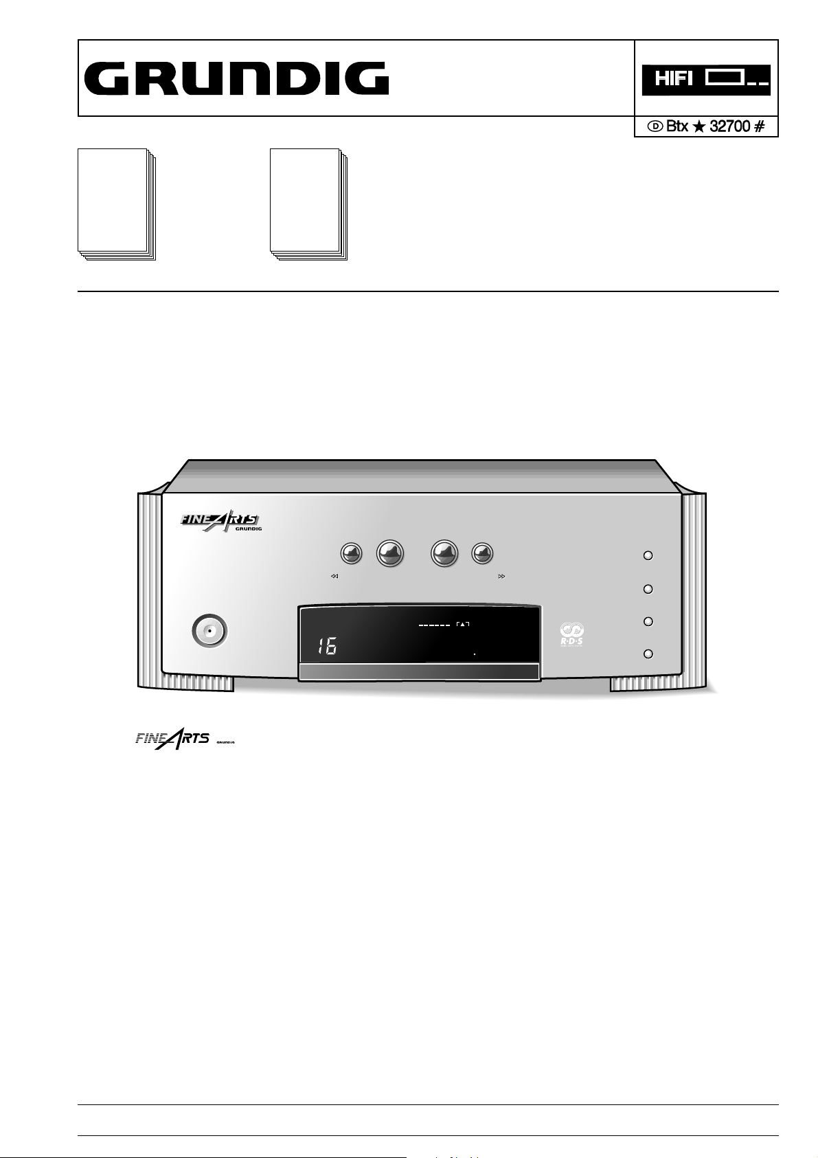
M 100-T
Sach-Nr./Part No.
72010-750.60
Zusätzlich erforderliche Unterlagen
für den
Komplettservice:
Additionally
required Service
Manuals for the
Complete Service:
by
by
Service
Manual
Sicherheit
Safety
Sach-Nr./Part No.
72010-800.00
M100-T
M100-T
MEMORY
MEMORY
M 100-T
TUNING
TUNING
POWER
POWER
MONO
MUTING
STEREO
FM 10060
by
M 100-T (9.55360-8150 / G.LG 01-50)
1
1
STATION
STATION
AUTO
TUNING
2
TUNING
2
CABLE
ANTENNA
MHz
CANCEL
CANCEL
BAND
BAND
IF/MONO
IF/MONO
Änderungen vorbehalten Printed in Germany Service Manual Sach-Nr.
GRUNDIG Service 1 - 1
Subject to alteration VK 233 0896 Service Manual Part No. 72010-750.60
Page 2

Allgemeiner Teil / General Section M 100-T
Es gelten die Vorschriften und Sicherheitshinweise gemäß dem Service Manual "Sicherheit",
Sach-Nummer 72010-800.00, sowie zusätzlich
die eventuell abweichenden, landesspezifischen
Vorschriften!
D
Inhaltsverzeichnis
Seite
Allgemeiner Teil ............................ 1 - 2 … 1 - 8
Meßgeräte / Hilfsmittel............................................................... 1 - 2
Technische Daten...................................................................... 1 - 3
Testmodus ................................................................................ 1 - 3
Ausbauhinweise......................................................................... 1 - 4
Bedienhinweise.......................................................................... 1 - 6
Abgleichvorschriften .................... 2 - 1 … 2 - 3
Schaltpläne und
Druckplattenabbildungen........... 3 - 1 … 3 - 13
Display ...................................................................................... 3 - 1
Verdrahtungsplan ...................................................................... 3 - 2
Schaltpläne
Tuner ..................................................................................... 3 - 4
Netzteil................................................................................... 3 - 8
Bedienteil ............................................................................. 3 - 12
Platinenabbildungen ....................................................... 3 - 3, 3 - 10
The regulations and safety instructions shall be
valid as provided by the "Safety" Service Manual,
part number 72010-800.00, as well as the
respective national deviations.
GB
Table of Contents
Page
General Section........................... 1 - 2 … 1 - 10
Test Equipment / Aids ............................................................... 1 - 2
Technical Data........................................................................... 1 - 3
Test Mode ................................................................................. 1 - 3
Disassembly Instructions ........................................................... 1 - 4
Operating Hints.......................................................................... 1 - 8
Adjustment Procedures................ 2 - 2 … 2 - 3
Circuit Diagrams and
Layout of PCBs ........................... 3 - 1 … 3 - 13
Display ...................................................................................... 3 - 1
Wiring Diagram .......................................................................... 3 - 2
Circuit Diagrams
Tuner ..................................................................................... 3 - 4
Power Supply ......................................................................... 3 - 8
Operating Board ................................................................... 3 - 12
Layout of PCBs.............................................................. 3 - 3, 3 - 10
Ersatzteillisten und
Explosionszeichnungen............... 4 - 1 … 4 - 2
Explosionszeichnung Gerät....................................................... 4 - 1
Ersatzteilliste............................................................................. 4 - 2
Allgemeiner Teil
Meßgeräte / Meßmittel
Wobbler
Meßsender
Stereocoder
Tongenerator
Oszilloskop
Digitalvoltmeter
NF-Voltmeter
Klirrfaktormeßgerät
Beachten Sie bitte das GRUNDIG Meßtechnik-Programm, das Sie
unter folgender Adresse erhalten:
GRUNDIG electronics GmbH
Würzburger Str. 150
D-90766 Fürth/Bay
Tel. 0911/703-0, Fax 0911/703-4479
Spare Parts Lists and
Exploded Views............................. 4 - 1 … 4 - 2
Exploded View Unit.................................................................... 4 - 1
Spare Parts List ......................................................................... 4 - 2
General Section
Test Equipment / Aids
Sweep generator
Test generator
Stereo coder
AF Generator
Oscilloscope
Digital Voltmeter
AF Voltmeter
Distortion Meter
Please note the Grundig Catalog “Test and Measuring Equipment”
obtainable from:
GRUNDIG electronics GmbH
Würzburger Str. 150
D-90766 Fürth/Bay
Tel. 0911/703-0, Fax 0911/703-4479
1 - 2 GRUNDIG Service
Page 3
M 100-T Allgemeiner Teil / General Section
MUTING
MONO
STEREO AUTO
ANTENNA CABLE
MHz
kHz
BA
LOUD
DIRECTPRO-LOGIC
MUTING
MONO
STEREO AUTO
ANTENNA CABLE
MHz
kHz
BA
LOUD
DIRECTPRO-LOGIC
Technische Daten
Empfindlichkeit
Mono (S/N = 26dB) ........................................................ ≤ 1,1µV
Stereo (S/N = 46dB)........................................................ ≤ 35µV
Klirrfaktor
Mono (1kHz, 40kHz dev.)................................................. ≤ 0,2%
Stereo (1kHz, 40kHz dev.) ............................................... ≤ 0,4%
Frequenzbereich (± 1,5dB) .......................................... 25…15000Hz
Nebenkanalempfindlichkeit
Mono Wide ± 300kHz...................................................... > 50dB
Narrow ± 300kHz .................................................. > 70dB
Stereo Wide ± 300kHz .................................................... > 50dB
Narrow ± 300kHz ................................................. > 60dB
Geräuschspannungsabstand (IEC Kurve A eff.)
40kHz dev., DIN A, Mono ....................................................75dB
40kHz dev., DIN A, Stereo ..................................................69dB
Abschwächer im Kabelmodus ...................................................12dB
Empfangsbereich
FM (25kHz Schritte) ......................................... 87,5…108,0MHz
MW (1kHz Schritte) ............................................. 522…1611kHz
Stromversorgung
Netzspannung ................................................................. 230V ~
Netzfrequenz ................................................................. 50/60Hz
Max. Leistungsaufnahme ................................................... < 9W
Gehäuse
Abmessungen (B x H x T) ............................. 270 x 95 x 310mm
Gewicht .............................................................................. 3,0kg
Technical Data
Input sensitivity
Mono (S/N = 26dB) ........................................................ ≤ 1.1µV
Stereo (S/N = 46dB)........................................................ ≤ 35µV
Distortion
Mono (1kHz, 40kHz dev.)................................................. ≤ 0.2%
Stereo (1kHz, 40kHz dev.) ............................................... ≤ 0.4%
Frequency response (± 1.5dB) ................................... 25…15,000Hz
Adjacent channel selectivity
Mono Wide ± 300kHz...................................................... > 50dB
Narrow ± 300kHz .................................................. > 70dB
Stereo Wide ± 300kHz .................................................... > 50dB
Narrow ± 300kHz ................................................. > 60dB
Signal-to-noise ratio (IEC curve A effective value)
40kHz dev., DIN A, Mono ....................................................75dB
40kHz dev., DIN A, Stereo ..................................................69dB
Attenuation in cable mode ........................................................ 12dB
Frequency ranges
FM (25kHz steps) ............................................. 87.5…108.0MHz
MW (1kHz steps)................................................. 522…1611kHz
Power supply
Mains voltage ................................................................... 230V~
Mains frequency ............................................................ 50/60Hz
Max. power consumption ................................................... < 9W
Cabinet
Dimensions (W x H x D) ................................ 270 x 95 x 310mm
Weight ................................................................................ 3.0kg
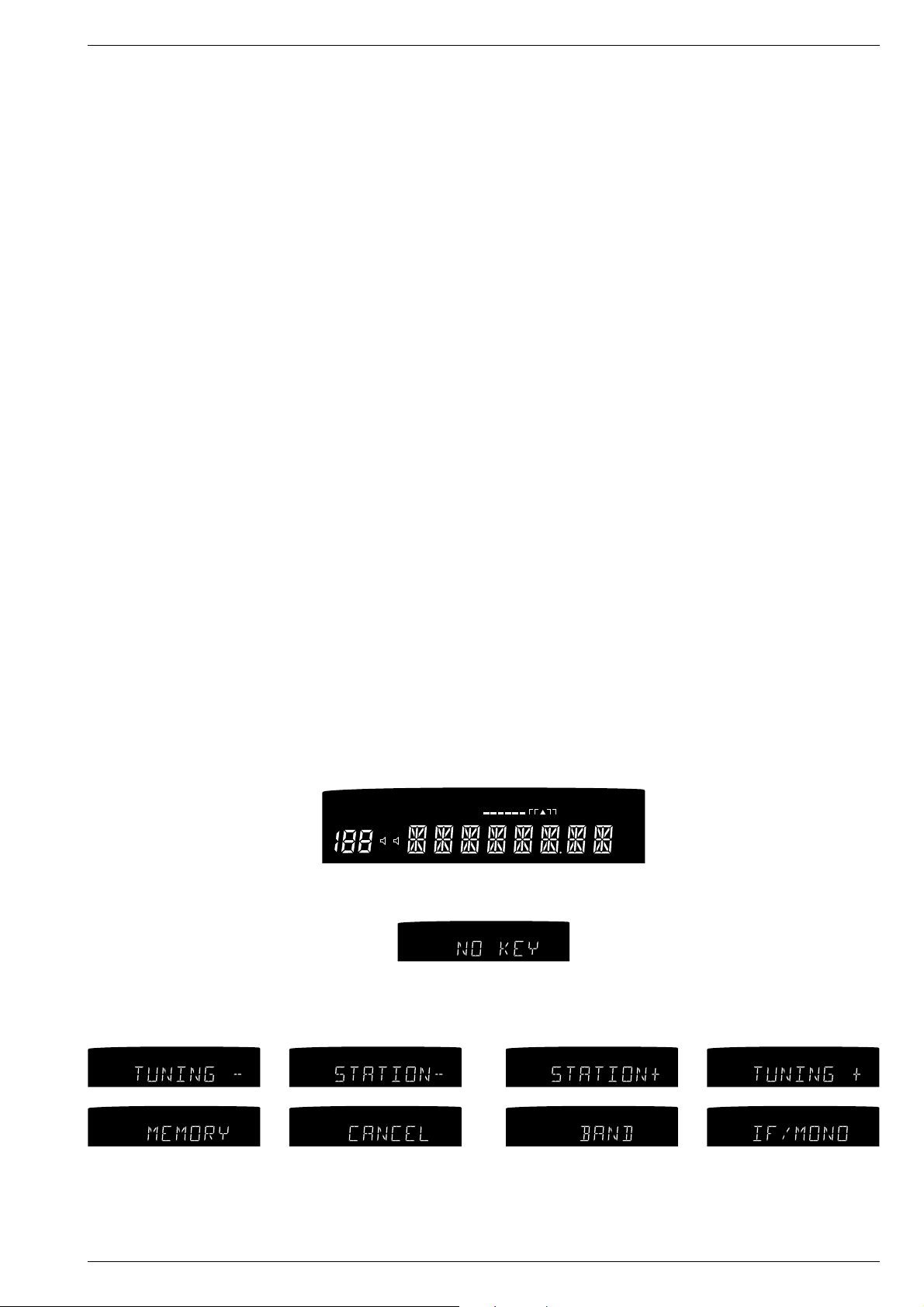
Testmodus
Aktivieren des Testmodus:
- Gerät ausschalten.
- Tasten "STATION "" und "TUNING T" gedrückt halten und Gerät
einschalten.
- Es werden jetzt nacheinander alle Segmente des Displays eingeschaltet.
MONO
MUTING
- Nach einigen Sekunden wechselt die Anzeige dann auf:
- Beim Drücken der einzelnen Tasten wird die jeweilige Taste im
Display angezeigt:
MUTING
MUTING
MONO
MONO
DIRECTPRO-LOGIC
LOUD
DIRECTPRO-LOGIC
LOUD
STEREO AUTO
BA
STEREO AUTO
BA
ANTENNA CABLE
ANTENNA CABLE
MONO
MUTING
STEREO AUTO
DIRECTPRO-LOGIC
MUTING
MONO
LOUD
DIRECTPRO-LOGIC
LOUD
BA
STEREO AUTO
BA
kHz
MHz
kHz
MHz
DIRECTPRO-LOGIC
LOUD
STEREO AUTO
BA
MUTING
ANTENNA CABLE
ANTENNA CABLE
MONO
DIRECTPRO-LOGIC
LOUD
BA
kHz
MHz
kHz
MHz
STEREO AUTO
Testmode
Activating the Testmode:
- Switch off the unit.
- Hold the buttons "STATION "" and "TUNING T" depressed and
switch on the unit.
- Now all segments in the display will be illuminated one after another.
ANTENNA CABLE
kHz
MHz
- After a few seconds the display changes to:
ANTENNA CABLE
kHz
MHz
- When pressing one of the buttons, the respective button is shown in
the display:
MUTING
MUTING
MONO
MONO
DIRECTPRO-LOGIC
LOUD
DIRECTPRO-LOGIC
LOUD
STEREO AUTO
BA
STEREO AUTO
BA
ANTENNA CABLE
ANTENNA CABLE
kHz
MHz
kHz
MHz
- Beenden des Testmodus durch Ausschalten des Gerätes.
GRUNDIG Service 1 - 3
- To end the testmode switch off the unit.
Page 4
Allgemeiner Teil / General Section M 100-T
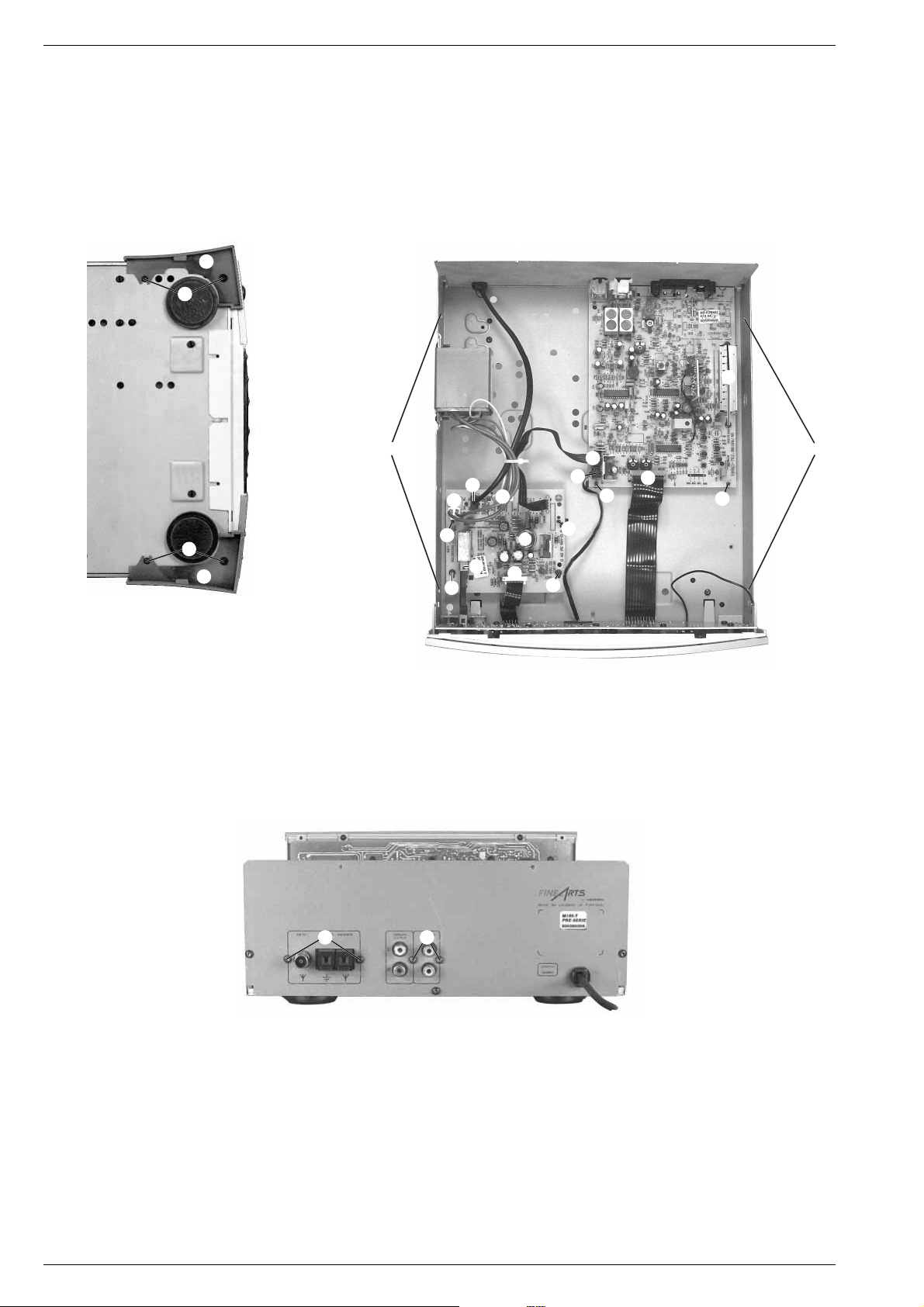
Ausbauhinweise
1. Öffnen des Gehäuses
- Die 4 Schrauben A herausschrauben und die Seitenblenden B
abnehmen (Fig. 1).
- Die 6 Schrauben C herausschrauben und den Deckel abnehmen
(Fig. 2).
Fig. 1 Fig. 2
B
A
Disassembly Instructions
1. Removing the cover
- Undo 4 screws A and take off the side covers B (Fig. 1).
- Undo 6 screws C and take off the cover (Fig. 2).
C C
H
D
O
N
E
M
J
F
J
CC
A
B
2. Tunerplatte ausbauen
- Die Steckverbinder D, E und F (Fig. 2) abziehen.
- Die 4 Schrauben G (Fig. 3) und die Schrauben H (Fig. 2) herausschrauben, die 2 Rastnasen J ausrasten und die Leiterplatte
herausnehmen.
Fig. 3
G G
Q
K
L
P
2. Removing the Tuner Board
- Open the connectors D, E and F (Fig. 2).
- Undo 4 screws G (Fig. 3), 2 screws H (Fig. 2), unhook the 2
catches J and take off the PCB.
Q
P
3. Netzteilplatte ausbauen (Fig. 2)
- Die Rastung K der Netztaste ausrasten.
- Die Steckverbinder D, L, M, N und O abziehen.
- Die 2 Schrauben P herausschrauben, die Rastnasen Q ausrasten
und die Leiterplatte herausnehmen.
1 - 4 GRUNDIG Service
3. Removing the Power Supply Board (Fig. 2)
- Disengage the mains button K.
- Open the connectors D, L, M, N and O.
- Undo 2 screws P, unhook the catches Q and take off the PCB.
Page 5
M 100-T Allgemeiner Teil / General Section
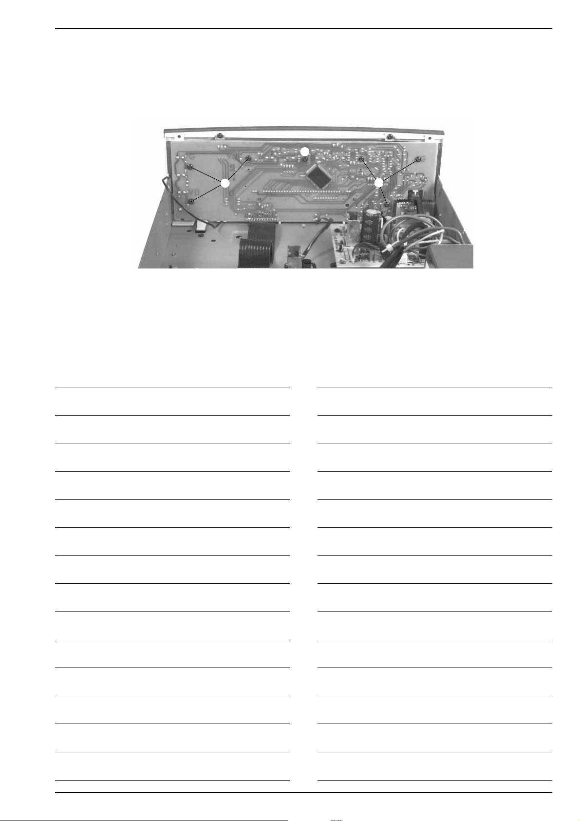
4. Bedienplatte ausbauen (Fig. 4)
- Die 7 Schrauben R herausschrauben.
- Bei Bedarf die Steckverbinder E, F und L (Fig. 2) abziehen.
- Die Leiterplatte herausnehmen.
Fig. 4
R
4. Removing the Control Board (Fig. 4)
- Undo 7 screws R.
- If necessary open the connectors E, F and L (Fig. 2).
- Take off the PCB.
R
R
Notizen / Notes
GRUNDIG Service 1 - 5
Page 6
1 - 6 GRUNDIG Service
Allgemeiner Teil / General Section M 100-T
Bedienhinweise
Hinweis: Dieses Kapitel enthält Auszüge aus der Bedienungsanleitung. Weitergehende Informationen entnehmen Sie bitte der gerätespezifi-
schen Bedienungsanleitung, deren Sachnummer Sie in der entsprechenden Ersatzteilliste finden.
Aufstellen
• Wollen Sie Ihren Empfänger in Regalwänden,
Schränken, etc. aufstellen, sorgen Sie bitte für
ausreichende Belüftung des Gerätes. Ein Freiraum
von mindestens 3 cm seitlich und oberhalb der
Anlage sowie 5 cm an der Rückseite sind
empfehlenswert.
• Verlegen Sie Netzkabel möglichst entfernt von den
Tonsignal-Leitungen, um störende Einstrahlungen zu
vermeiden.
• Achten Sie beim Anschließen auf die Kennzeichnungen der Leitungen bzw. Buchsen- oder
Rückwand-Beschriftungen, um ein Vertauschen der
Anschlüsse zu vermeiden. Ein Verpolen der
Anschlüsse kann den Klangeindruck erheblich
beeinträchtigen.
Wichtig: Alle Geräten ausschalten bevor
irgendwelche Verbindungen hergestellt werden.
Netzanschluß
• Schließen Sie Ihr Gerät nur an Wechselspannung
230V~, 50/60 Hz an. Das Typenschild befindet
sich auf der Rückseite des Geräts.
• Wollen Sie Ihr Gerät zentral über einen Verstärker
dieser Serie einschalten und über die SystemFernbedienung ausschalten, schließen Sie das
Gerät an einen der drei WechselspannungsAusgänge (AC OUTLETS) des Verstärkers an. Um
dieser Funktion zu verwenden, stellen Sie sicher,
daß die Power-Taste des Tuners in Position “ON”
steht. Der Netzschalter des Verstärkers dient dann
als Zentralschalter.
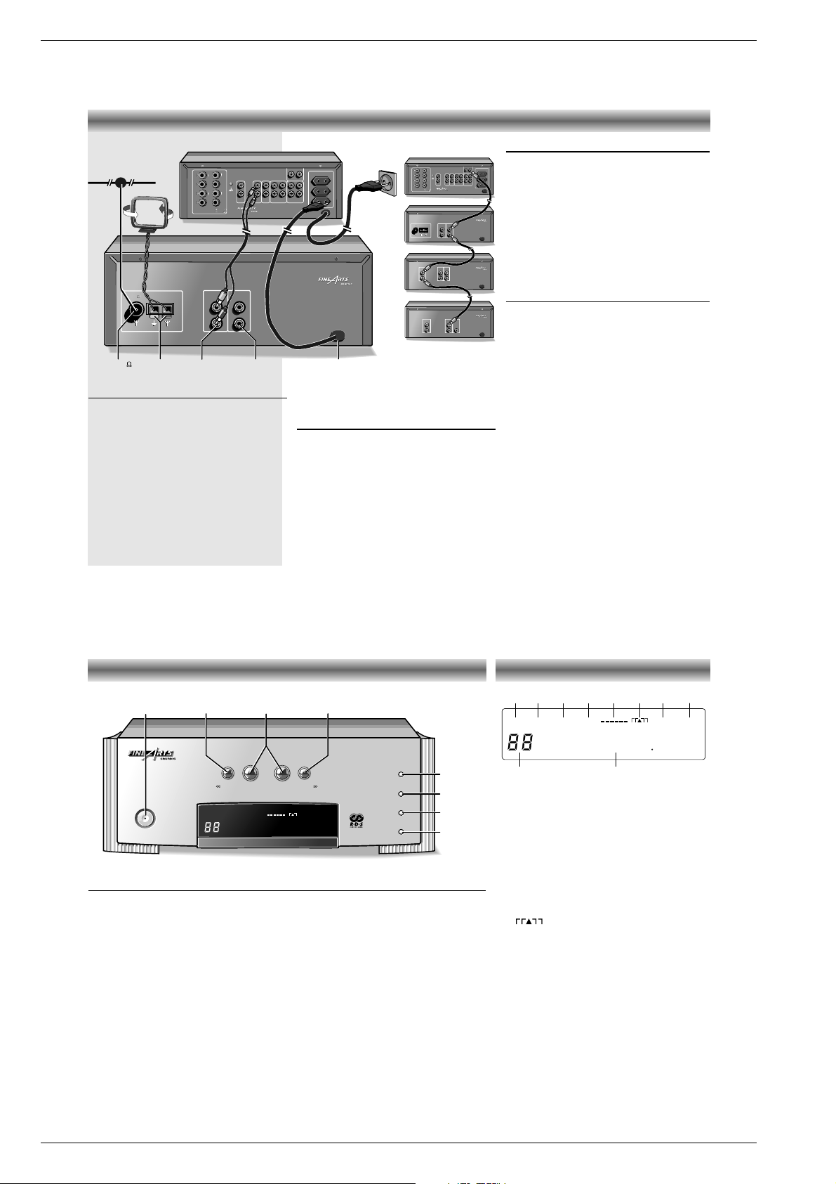
INSTALLATION
Anschluß am Verstärker
Schließen Sie Ihren TUNER an die entsprechenden
Eingangs-Buchsen des Verstärkers an.
• Verbinden Sie dazu die Buchsen ANALOG OUT-
PUT mit den Buchsen TUNER des Verstärkers.
Achten Sie beim Anschließen der Verbindungskabel
auf die r
ichtige Zuordnung der Stereo-Kanäle:
L = linker Kanal (weiß), R = rechter Kanal (rot).
Möchten Sie Ihren Tuner über den Verstärker fernbedienen, muß die Innerverbindung über die RCBUS-Kabel gegeben sein.
• Verbinden Sie
RC-BUS
-Buchsen miteinander, wie
links beschrieben.
Antennenanschluß
Für beste Empfangsqualität, insbesondere bei FMStereo Sendungen, ist eine leistungsfähige AntennenAnlage unerläßlich (Breitbandkabelanschluß,
Einzelantenne oder Gemeinschaftsantenne).
FM 75 Ω
• Die Buchse FM 75 Ω dient zum Anschluß des
Tuners an eine Gemeinschaftsantenne, ein
Breitbandkabelsystem oder an eine UKWAußenantenne mit einer Impedanz von 75 Ohm.
• Falls keine dieser Anschlußmöglichkeiten zur
Verfügung stehen sollte, können Sie den
mitgelieferten Antennendraht für Ortssender
benutzen (jedoch möglicherweise mit mangelhafter
Empfangsqualität). Diese Wurfantenne sollte aber in
der Länge nicht verändert werden.
AM LOOP ANTENNA
•
Für AM-Empfang die mitgelieferten Drähte mit den
Anschlußklemmen AM LOOP ANTENNA verbinden
und die Antenne so positionieren, daß ein möglichst
guter Empfang erreicht wird.
• Anstelle der Rahmen-Antenne können an diese
Buchsen auch Hochantenne b und Erde e
angeschlossen werden.
Anmerkung: Die Rahmenantenne nicht auf das Gerät
stellen, da dadurch Störsignale erzeugt werden können.
byby
ANALOG
OUTPUT
ANALOG
OUTPUT
RC-BUS
230 V
~
50/60 Hz
L
R
FM 75
AM/LOOP
AM/LOOP
ANTENNA
ANALOG
OUTPUT
RC-BUS
L
R
FM 75
ANTENNA
AM LOOP
ANTENNA
FM 75
MAINS ~RC-BUS
230 V
~
50/60 Hz
FM
byby
RC-BUS
230 V
~
50/60 Hz
L
R
RC-BUS
PHONO
PHONO
L
R
230 V
~
50/60 Hz
SPEAKERS A OR B – 4 TO 8/16
~
SWITCHED TOTAL 100W
L
R
L
R
SPEAKERS A AND B – 8 TO 16
SPEAKERS A OR B – 4 TO 8/16
SPEAKERS A AND B – 8 TO 16
–
+
–
+
ABA
B
–
+
–
+
TAPE
TAPE
ININOUT
OUT
AUX
AUX
ININOUT
OUT
TUNER
TUNERCDCD
M100 A
M100 T
AM
byby
ANALOG
OUTPUT
RC-BUS
230 V
~
50/60 Hz
L
R
FM 75
AM/LOOP
AM/LOOP
ANTENNA
ANALOG
OUTPUT
RC-BUS
L
R
FM 75
ANTENNA
230 V
~
50/60 Hz
byby
RC-BUS
230 V
~
50/60 Hz
L
R
RC-BUS
PHONO
PHONO
L
R
230 V
~
50/60 Hz
SPEAKERS A OR B – 4 TO 8/16
~
SWITCHED TOTAL 100W
L
R
L
R
SPEAKERS A AND B – 8 TO 16
SPEAKERS A OR B – 4 TO 8/16
SPEAKERS A AND B – 8 TO 16
–
+
–
+
ABA
B
–
+
–
+
TAPE
TAPE
ININOUT
OUT
AUX
AUX
ININOUT
OUT
TUNER
TUNERCDCD
M 100 A
RC-BUS
M 100 T
M 100 CF
byby
230 V
~
50/60 Hz
230 V
~
50/60 Hz
LINE
OUT
RC-BUS
L
R
LINE
IN
M 100 CD
byby
230 V
~
50/60 Hz
230 V
~
50/60 Hz
DIGITAL
OUTPUT
RC-BUS
ANALOG
OUTPUT
L
R
Vorderseite des Tuners
POWER Dieser Schalter wird zum Ein- und Ausschalten des Geräts verwendet.
TUNING
QR
Mit diesen Tasten starten Sie den Sendersuchlauf (AUTO TUNING) oder schalten
die Frequenz in die gewünschte Richtung Schritt für Schritt (MANUAL TUNING)
weiter.
Halten Sie die Taste länger gedrückt, erfolgt die Weiterschaltung im Schnellgang.
STATION 1 2 Mit diesen Tasten schalten Sie die Speicherplätze in aufsteigender (>) oder
abfallender (<) Richtung durch.
MEMORY Diese Taste speichert einen eingestellten Sender auf den jeweils niedrigsten,
freien Speicherplatz.
Längeres drücken dieser Taste startet die Funktion AUTO STORE.
CANCEL Mit dieser Taste löschen Sie einzelne Speicherplätze oder den gesamten
Speicherinhalt (länger als 10 Sekunden gedrückt halten).
BAND Mit dieser Taste schalten Sie zyklisch zwischen den Bändern
FM ANTENNA,
FM CABLE und MW.
IF/MONO Durch wiederholtes Drücken dieser Taste ändern Sie den FM-Empfangsmodus
:
STEREO WIDE ➧ STEREO NARROW
➧ MONO
WIDE ➧MONO NARROW
➧
STEREO WIDE ➧usw.
BEDIENELEMENTE DISPLAY
1 MUTING – euchtet auf, wenn Funktion MUTING
aktiviert ist.
2 MONO – Leuchtet auf, wenn die Funktion
MONO aktiviert wurde.
3 STEREO – Leuchtet auf, wenn im Wellenbereich
FM Stereo-Sendungen empfangen werden.
4 AUTO – Diese Anzeige leuchtet auf, wenn die
Funktion AUTO TUNING aktiv ist.
5 Signalstärke-Anzeige – Je mehr Striche im
Display erscheinen, desto stärker empfangen Sie
den eingestellten Sender.
6 –
Zeigt die ausgewählte FM-IF-Bandbreite
(NARROW/WIDE). Bei exakter
Abstimmung auf die Sendermitte leuchtet das
Dreieck auf.
7 ANTENNA – leuchtet auf, wenn der Antennen-
abschwächer ausgeschaltet ist. (FM ANTENNA).
8 CABLE – leuchtet auf, wenn bei Breitbandkabel-
empfang der Antennenabschwächer
eingeschaltet ist. (FM CABLE).
9 Station number Siebensegment-Anzeige – Hier
wird die Nummer des gewählten Speicherplatzes
(1bis 59) angezeigt.
0 14 Segment-Anzeige – für (RDS) Sendername,
Frequenzen, Radiotext, RDS Zeit, Programmart
oder Informationen.
MUTING
MONO
STEREO AUTO
ANTENNACABLE
########
MHz
12 3 4 5 6708
kHz
9
by
by
POWER
POWER
M100-T
M100-T
MEMORY
BAND
IF/MONO
MEMORY
BAND
CANCEL
CANCEL
IF/MONO
STATION
STATION
TUNING
TUNING
TUNING
TUNING
1
2
2
MUTING
MONO
STEREO AUTO
ANTENNA CABLE
########
MHz
MEMORY
CANCEL
TUNINGSTATIONTUNING
POWER
BAND
IF/MONO
56
12
1
Page 7

GRUNDIG Service 1 - 7
M 100-T Allgemeiner Teil / General Section
BEDIENUNG
Wellenbereichswahl
• Wählen Sie den gewünschten Wellenbereich
(
FM ANTENNA,
FM CABLE oder MW),
indem Sie die Fortschalt-Taste BAND drücken.
•
Jedes Betätigen der Taste schaltet zum nächsten
Wellenbereich weiter in der Reihenfolge:
FM
ANTENNA- FM CABLE - MW - FM ANTENNA
.
Empfangen Sie Ihre Sender über das Breitbandkabel einer öffentlichen oder privaten BetreiberGesellschaft, kann es vorkommen, daß an Ihrer
Antennen-Dose ein sehr hoher Pegel anliegt, der
zu Störungen führen kann.
•
Selektieren Sie deshalb FM CABLE, um den Eingangsabschwächer einzuschalten. Dadurch
wird die Empfindlichkeit des Antenneneinganges
herabgesetzt und Störungen durch das Kabel
vermieden. Diese Einstellung wird nach 5
Sekunden automatisch abgespeichert.
FM-Empfangsmodus
WIDE/NARROW, STEREO/MONO
Der FM-Empfangsmodus wird bei jedem Einschalten
des Tuners automatisch auf Stereo und Wide gestellt.
Es gibt immernoch Sender, die, aufgrund schwacher
Signalausstrahlung oder Störungen durch benach
barte Sender, nicht störfrei übertragen werden.
Die Taste
IF/MONO
bietet eine schrittweise
Antennenabschwächung zur Beseitigung dieser
Störungen und Geräusche.
•
Bei gestörtem FM-Empfang drücken Sie IF/MONO.
Der Modus wechselt zu STEREO NARROW
und umgeht damit Störungen der Nachbarsender.
• Wenn Stereo-Narrow-Empfang weiterhin nicht
geräuschfrei verläuft, drücken Sie erneut IF/MONO,
um MONO WIDE auszuwählen. Nun wird
durch den Monoempfang das Rauschen
aufgrund schwachen Empfangs unterdrückt.
•
Es wäre ungewöhnlich, wenn Sie jetzt immernoch
Rauschen hören, aber ein letzter Schritt ist die
Auswahl von MONO NARROW durch erneutes
Drücken von IF/MONO. Damit haben Sie die
höchste Stufe der Störgeräuschunterdrückung
erreicht, sowohl was benachbarte als auch
schwach zu empfangene Sender betrifft.
➥
➥
➥
MUTING
STEREO
ANTENNA
FM 9350
MHz
MUTING
STEREO
ANTENNA
FM 9350
MHz
MONO ANTENNA
FM 9350
MHz
MONO ANTENNA
FM 9350
MHz
➥
MUTING
ANTENNA
FM 8750
MHz
MUTING
CABLE
FM 8750
MHz
➥
MW 528
kHz
➥
➥
SPRACHWAHL
Sprachwahl
Sie können die Anzeige der Programmart in den
Sprachen Deutsch, Englisch, Französisch,
Italienisch, Portugiesisch, Spanisch,
Niederländisch und Schwedisch aufrufen.
• Halten Sie im ausgeschalteten Zustand die
Taste IF/MONO gedrückt und schalten Sie
den Tuner ein.
– Im Display erscheint die aktuelle Sprache.
• Mit den Tasten STATION 1 2 können Sie die
gewünschte Sprache aufrufen.
• Speichern Sie Ihre Wahl mit Taste MEMORY.
SYSTEMFERNBEDIENUNG
➥
➥
➥
BAYERN 3
➥
13 45
ARD-RADI
MUTING
STEREO
ANTENNA
FM 9790
MHz
MUTING
STEREO
ANTENNA
FM 10720
MHz
FREE
STEREO
ANTENNA
FM 9790
MHz
MUTING
Auswahl des Tuners:
• Drücken Sie die Taste TUNER/pty.
Aufrufen eines Senderspeichers
• Drücken Sie die Tasten $ STATION #, um die
gespeicherten Speicherplätze nacheinander
aufzurufen. Leere Plätze werden übersprungen.
• Geben Sie die Speicherplatznummer mit den
Zifferntasten 1...0 direkt ein:
• Bei einstelligen Speicherplatznummern
betätigen Sie die entsprechende Zifferntaste
nur kurz.
• Um zweistellige Nummern zu speichern,
drücken Sie die erste Ziffer eine längere
Zeit, bis diese auf die linke Seite des
Displays springt: 4--.
• Geben Sie danach die Einerstelle ein.
– Haben Sie einen Speicherplatz angewählt,
der (noch) nicht belegt ist, erscheint für
kurze Zeit 'FREE' im Display. Danach
schaltet das Gerät auf den zuletzt
eingestellten Speicherplatz zurück.
Umschalten der Anzeige
• Drücken Sie die Taste TXT/6, wechselt die
Anzeige zwischen Stationsnamen (RDS oder
eigen vergeben), RDS-Zeit, RADIOTEXT (bei
RDS-Sendern) und Frequenz.
– Bei Anzeige des Stationsnamens wird links
daneben nur die Speicherplatznummer
angezeigt.
STATION
TUNER/pty
Z
T
E
$
#
2
1 2 3 4 5
6 7 9 0
TXT/6
Diese Fernbedienung ist Teil des Lieferumfanges
des Verstärkers M100 A oder M100 ADPL.
Folgende Radiofunktionen können über die
Fernbedienung ausgeführt werden:
ENGLISH
➥
DEUTSCH
1 2 3 4 5
6 7 8 9 0
TV
SAT
REAR
TUNER/pty VCR
RECORD
1
CD/disc
TAPE 1 2
TXT/6
TV
SAT
88
HIFI
8
–
AV
P
P
P
P
P
P
CENTRE
SURROUND
+
Install
2
E
$
#
STATION
3
T
Z
HIFI TV/VCR
a
VOLUME
A/V REMOTE CONTROL-URC1
8
1
Page 8

1 - 8 GRUNDIG Service
Allgemeiner Teil / General Section M 100-T
Operating Hints
Note: This chapter contains excerpts from the operating instructions. For further particulars please refer to the appropriate user instructions the
part number of which is indicated in the relevant spare parts list.
Programmart (PTY)
RDS bietet Ihnen die Möglichkeit, FM-Sender
nach Programmarten auszuwählen.
Mehr und mehr Sender codieren ihre
Programmart und erlauben damit eine
erfolgreiche Suche mit der Funktion PTY. Der
übertragene Code steht jedoch unter
Verantwortung des Radiosenders.
Es sind 6 Programmarten definiert.
• Drücken Sie die Taste TUNER/pty
– Das Display zeigt die aktuelle Programmart.
• Durch Drücken der Tasten
$ STATION #
innerhalb von 2 Sekunden starten Sie den
Aufruf der Programmarten nacheinander.
– Nach 2 Sekunden beginnt das Gerät die
gespeicherten Sender zu scannen, um die
gewünschte Programmartübertragung zu
finden. Sobald dies der Fall ist, wird der
Sender eingestellt.
– Wird die aktuelle Kennung von keiner Station
übertragen, zeigt das Display für kurze Zeit:
'NONE' ('KEINE').
Was ist unter Programmart zu verstehen?
NEWS = Nachrichtendienste, Politik und
Zeitgeschehen, Spezielle
Wortprogramme
SPORT = Sportsendungen
CULTURE = Lernen und Weiterbildung, Hörspiel
und Literatur, Kultur, Kirche und
Gesellschaft, Wissenschaft,
Unterhaltendes Wort
POP = Popmusik, Rockmusik
CLASSIC = Leichte und ernste klassische Musik
OTHER = Unterhaltungsmusik, Musiksendungen,
die sich den vorgenannten Programm
-
arten nicht zuordnen lassen
SYSTEMFERNBEDIENUNG
_
RDS-DATA
AB_
NONE
➥
➥
NEWS
SPORT
CULTURE
Sendernamen vergeben
Empfangen Sie Sender, die den RDS-Code nicht
ausstrahlen, können Sie jeder Station einen
Namen Ihrer Wahl geben.
• Drücken Sie auf der Fernbedienung die Taste
TXT/
6 länger als 1 Sekunde.
• Mit den Tasten Q oder R können Sie die
Eingabemarke, den Cursor, in die jeweilige
Richtung bewegen. Ihnen stehen insgesamt 8
Eingabestellen zur Verfügung.
• Mit den Tasten $ STATION # laufen Sie
vorwärts (UP) oder rückwärts (DOWN) durch
das Alphabet, das Leerzeichen und die
Zahlen von 0 - 9.
• Wollen Sie die Eingabe beenden, den
Eingabemodus verlassen und abspeichern,
drücken Sie erneut die Taste TXT/
6.
Anmerkung:
Versuchen Sie, einem Sender, der RDS-Codes
ausstrahlt, einen Namen Ihrer Wahl zu geben,
informiert Sie das Display mit der Anzeige RDS-
DATA über die Eingabesperre.
Löschen eines Namens
• Drücken Sie im Eingabemodus die Taste
CANCEL, wird der bisherige Name gelöscht
und die Einfügemarke springt an die erste
Position.
Setting up
• If you want to set up your tuner on a shelf, in a
cabinet or any other type of enclosure, always
ensure that sufficient ventilation is available. An
open space of at least 3 cm at the sides and
the top, and 5 cm at the back of your system is
required.
• Place the power supply cable as far as
possible from the sound signal lines in order to
avoid disturbing signal interference.
• When making connections, always note the
identification markings on the cables and
sockets, as well as those on the back of the
unit, in order to avoid improper connections.
Improper connections can considerably impair
sound quality.
Important: Switch off all units in your system
before making any connections
.
Power supply connection
• Only connect the unit to a 230V~, 50/60 Hz
a.c. power source. The rating is found on the
back of the unit.
• If you want to switch your unit on and off via
an amplifier from this series, or with the system
remote control, connect the mains plug of the
tuner to one of the AC OUTLETS of your amplifier. To use this capabilitiy, ensure that the
power switch of the tuner is switched to the
ON position. The amplifier´s power switch can
then be used as the main switch for all the
units.
INSTALLATION
Connection to the amplifier
Your tuner should be connected to the
corresponding input sockets on the amplifier.
• Connect the ANALOG OUTPUT sockets to the
TUNER input sockets on the amplifier.
When connecting the cables, ensure the proper
arrangement
of the stereo channels:
L = left channel (white), R = right channel (red).
If you would like to use your amplifier to switch on
and remotely
control your tuner, the units must be
interconnected by the RC-BUS lines.
• Interconnect the
RC-BUS sockets of the units in
your system as shown on the side.
Antenna connection
Only a good antenna system (broadband cable
connection to your own
antenna system, or a common
house antenna system) can guarantee optimum
reception quality, especially for FM stereo broadcasts.
FM 75 Ω
•
The FM 75 Ω socket is used for connection to the
Community
or Cable Antenna System or to a
roof-mounted FM antenna with an impedance of
75 Ω.
• If non of these are available, you may use the
cast (wire)
antenna supplied for nearby station
(reception could be poor).
You should not,
however, change the length of the cast antenna.
AM LOOP ANTENNA
•
For AM reception, connect the supplied wires to
the AM LOOP ANTENNA terminals and position the
antenna for best reception.
• The elevated antenna b as well as earth e can
also be
connected to these sockets in place of the
frame antenna.
Note: do not place the AM loop antenna on the unit,
as this unit employs a computing device which could
cause interference.
byby
ANALOG
OUTPUT
ANALOG
OUTPUT
RC-BUS
230 V
~
50/60 Hz
L
R
FM 75
AM/LOOP
AM/LOOP
ANTENNA
ANALOG
OUTPUT
RC-BUS
L
R
FM 75
ANTENNA
AM LOOP
ANTENNA
FM 75
MAINS ~RC-BUS
230 V
~
50/60 Hz
FM
byby
RC-BUS
230 V
~
50/60 Hz
L
R
RC-BUS
PHONO
PHONO
L
R
230 V
~
50/60 Hz
SPEAKERS A OR B – 4 TO 8/16
~
SWITCHED TOTAL 100W
L
R
L
R
SPEAKERS A AND B – 8 TO 16
SPEAKERS A OR B – 4 TO 8/16
SPEAKERS A AND B – 8 TO 16
–
+
–
+
ABA
B
–
+
–
+
TAPE
TAPE
ININOUT
OUT
AUX
AUX
ININOUT
OUT
TUNER
TUNERCDCD
M100 A
M100 T
AM
byby
ANALOG
OUTPUT
RC-BUS
230 V
~
50/60 Hz
L
R
FM 75
AM/LOOP
AM/LOOP
ANTENNA
ANALOG
OUTPUT
RC-BUS
L
R
FM 75
ANTENNA
230 V
~
50/60 Hz
byby
RC-BUS
230 V
~
50/60 Hz
L
R
RC-BUS
PHONO
PHONO
L
R
230 V
~
50/60 Hz
SPEAKERS A OR B – 4 TO 8/16
~
SWITCHED TOTAL 100W
L
R
L
R
SPEAKERS A AND B – 8 TO 16
SPEAKERS A OR B – 4 TO 8/16
SPEAKERS A AND B – 8 TO 16
–
+
–
+
ABA
B
–
+
–
+
TAPE
TAPE
ININOUT
OUT
AUX
AUX
ININOUT
OUT
TUNER
TUNERCDCD
M 100 A
RC-BUS
M 100 T
M 100 CF
byby
230 V
~
50/60 Hz
230 V
~
50/60 Hz
LINE
OUT
RC-BUS
L
R
LINE
IN
M 100 CD
byby
230 V
~
50/60 Hz
230 V
~
50/60 Hz
DIGITAL
OUTPUT
RC-BUS
ANALOG
OUTPUT
L
R
Page 9

GRUNDIG Service 1 - 9
M 100-T Allgemeiner Teil / General Section
Front of the tuner
POWER This button is used for switching the tuner on and off.
TUNING
QR
You use these buttons to start the station search (AUTO TUNING) or to
advance the frequency step by step (MANUAL TUNING). If you keep the
button depressed, station search is accelerated.
STATION 1 2 These buttons are used to scroll through the station memory in ascending (>) or
descending (<) order.
MEMORY This button stores the actual station at the lowest empty memory location.
When pressing this button longer, the AUTO STORE function will be started.
CANCEL This button is used to delete individual memory locations or, if desired, the
entire memory contents (by keeping the button depressed for more than 10 seconds).
BAND
This button is used to switch to the FM ANTENNA, FM CABLE and MW bands.
IF/MONO
Pressing this button repeatedly switches the FM reception mode to STEREO WIDE ➧
STEREO NARROW
➧ MONO
WIDE ➧MONO NARROW ➧STEREO WIDE ➧etc.
OPERATING ELEMENTS DISPLAY
1 MUTING – This indicates that the MUTING
function is active.
2 MONO – This comes on if the MONO function
is activated.
3 STEREO – This indicates that the tuner is
receiving FM stereo broadcasts
4 AUTO – This indicates that the AUTO TUNING
function is active
5 Signal strength – The more dashes you can see,
the stronger the reception of the station you have
tuned to.
6 – Shows the chosen FM IF bandwidth
(NARROW/WIDE) and the triangle
lights up if the unit is exactly tuned to a station.
7 ANTENNA – comes on when the antenna
attenuator is switched off (FM ANTENNA).
8 CABLE – comes on during broadband cable
reception if the antenna attenuator is switched on
(FM CABLE).
9 Station number seven-segment display – This
shows the number of the selected memory
location (1 to 59)
0 14-segment display – for (RDS) station name,
frequency, radiotext, RDS time, selected
programme type or messages.
MUTING
MONO
STEREO AUTO
ANTENNACABLE
########
MHz
12 3 4 5 6708
kHz
9
by
by
POWER
POWER
M100-T
M100-T
MEMORY
BAND
IF/MONO
MEMORY
BAND
CANCEL
CANCEL
IF/MONO
STATION
STATION
TUNING
TUNING
TUNING
TUNING
1
2
2
MUTING
MONO
STEREO AUTO
ANTENNA CABLE
########
MHz
MEMORY
CANCEL
TUNINGSTATIONTUNING
POWER
BAND
IF/MONO
56
12
1
OPERATION
Selecting the wave band
•
Select the desired wave band (FM ANTENNA,
FM CABLE or MW) by pressing BAND.
• Pressing this button switches to the next wave
band in the following order:
FM ANTENNA- FM
CABLE - MW - FM ANTENNA
– The display shows the selected band.
If you receive broadcasts via broad band cable
of a public or private cable service, there may
be high signal inputs at your antenna terminal,
which may in turn cause reception disturbances.
•
If this is the case, select FM CABLE to switch on
the input attenuator. This reduces the antenna
input sensitivity, thus reducing disturbances. This
setting is automatically stored after 5 seconds.
FM reception
WIDE/NARROW, STEREO/MONO
The FM reception mode is automatically set to stereo
and wide every time automatic tuning is started.
Still, there are stations with disturbances or noise
in the audio signal, due to weak signal or interference of adjacent (neighbour) stations.
The IF/MONO button provides a step-by-step pro
-
gressive attenuation of those disturbances or noise.
• When the FM reception is disturbed, press
IF/MONO. The reception mode switches to
‘STEREO NARROW’ thus avoiding
interference from strong neighbour stations.
•
If stereo narrow reception still exhibits too much
disturbing noise press IF/MONO again to
select ‘MONO WIDE’. Now the mono function
will reduce noise due to weak reception.
• It is unlikely that you still hear noise but a last
step is to select ‘MONO NARROW’ by pressing
IF/MONO again. You have now selected the
highest noise disturbance reduction both for neigh
-
bour station interference and for weak reception
➥
➥
➥
MUTING
STEREO
ANTENNA
FM 9350
MHz
MUTING
STEREO
ANTENNA
FM 9350
MHz
MONO ANTENNA
FM 9350
MHz
MONO ANTENNA
FM 9350
MHz
➥
MUTING
ANTENNA
FM 8750
MHz
MUTING
CABLE
FM 8750
MHz
➥
MW 528
kHz
➥
➥
LANGUAGE SELECTION
Language selection
You can call up the programme type display in
the following languages: english, german,
french, portuguese, spanish, italian, dutch, and
swedish.
• Keep the IF/MONO button pressed while the
unit is turned off, and then turn on the tuner.
– The current language appears in the display.
• By using the STATION 1 2 buttons you can
call up the desired language.
• Store your selection by pressing the MEMORY
button.
➥
ENGLISH
DEUTSCH
Page 10

1 - 10 GRUNDIG Service
Allgemeiner Teil / General Section M 100-T
SYSTEM REMOTE CONTROL
STATION
TUNER/pty
Z
T
E
$
#
2
1 2 3 4 5
6 7 9 0
TXT/6
Selecting the TUNER:
• Press the TUNER/pty button.
Selecting stations:
• Press the $ STATION # buttons to call up the
stored memory locations one after another.
Empty locations will be skipped.
• You can also directly select the memorized
stations with the numeric buttons 1...0:
• For one-place memory location numbers,
press the corresponding button only briefly.
• For two-place number, first press the first
number longer until this number jumps to the
left side of the display: 4-.
• Then enter the second number.
– If you have selected a memory location to
which no station has been assigned (yet),
'FREE' appears briefly in the display.
The unit then switches to the most previously
set memory location.
Changing display indication:
• Pressing TXT/6 briefly switches the display
mode between (when available) station name
(RDS or one you have entered), RDS-TIME,
RADIOTEXT (with RDS stations), and frequency.
–
When the station name is displayed, only the
memory location number is displayed to the left
of the name.
This remote control is supplied with the
amplifier M100 A or M100 ADPL.
The following radio functions can be carried
out with the remote control:
Programme type (PTY)
RDS allows you to select FM stations according
to programme type. More and more stations are
codifying their programme type allowing efficient
search with the PTY function. The transmitted code
is however, the responsibility of the radio station.
There are 6 programme categories.
• Press TUNER/pty
– The display shows the actual programme type.
•
By pressing within 2 seconds the $ STATION #
buttons, you can call up the programme types
one after another.
– After 2 seconds the unit starts scanning the
memorized stations to find a station
broadcasting the required programme type.
As soon as such a station is found it is tuned
to.
– If there are no stations broadcasting a given
programme type, the display briefly shows:
'NONE'.
What is meant by programme types?
NEWS = news service, politics and current
events, special informative reports
SPORT = sports
CULTURE = learning and continuation of
education, radio plays, literature,
culture, church and society, science,
light entertainment programmes
POP = pop music, rock music
CLASSIC = light and serious classical music
OTHER = easy music, programmes that cannot
be assigned to one of the above
mentioned programme types.
SYSTEM REMOTE CONTROL
_
RDS-DATA
AB_
NONE
➥
➥
NEWS
SPORT
CULTURE
Assigning station names:
Stations which do not transmit the RDS code can
be assigned any name of your choice.
• Press TXT/
6 on the remote control longer than
1 second
• With Q or R , you can move the cursor
in the desired direction. You can enter up to
eight characters.
• With $ STATION #, you can move forward
and backward through the alphabet, the
numbers 0-9 and to the space key.
• When you are ready to conclude an input
and exit the input mode to store a name,
press TXT/
6 again.
Note:
If you attempt to assign a name to a station
which transmits the RDS code, RDS-DATA
appears in the display, indicating that a name
cannot be assigned.
Deleting a name
• If you press CANCEL when the input mode is
selected, the previous name is deleted and the
cursor jumps to the first (left) position.
1 2 3 4 5
6 7 8 9 0
TV
SAT
REAR
–
TUNER/pty VCR
RECORD
1
CD/disc
TAPE 1 2
TXT/6
TV
SAT
88
HIFI
8
AV
P
P
P
P
P
P
CENTRE
SURROUND
+
Install
2
E
$
#
STATION
3
T
Z
HIFI TV/VCR
a
VOLUME
A/V REMOTE CONTROL-URC1
8
MUTING
STEREO
ANTENNA
FM 9790
1
FREE
MUTING
STEREO
ANTENNA
FM 10720
BAYERN 3
➥
13 45
➥
ARD-RADI
MUTING
➥
STEREO
FM 9790
ANTENNA
MHz
MHz
MHz
➥
Page 11

M 100-T Abgleichvorschriften / Adjustment Procedures M 100-T Abgleichvorschriften / Adjustment Procedures
D
Abgleichvorschriften
Meßgeräte:
Wobbler, Meßsender, Stereocoder, Tongenerator, Oszilloskop, Digitalvoltmeter, NF-Voltmeter, Klirrfaktormeßgerät
Hinweis:
Das Frontend ist ein komplett abgeglichener Baustein. Nur das ZF-Filter muß dem ZF-Verstärker angeglichen werden (1). Die Abstimmspannungen
des Frontends haben folgende Größen:
87,5 MHz = typ. 1,6 V min 1,3 V
108 MHz = typ. 8,0 V max 9 V
Beim FM-Abgleich muß das Gerät in Stellung "ZF-WIDE" betrieben werden!
Abgleich Vorbereitung Abgleichprozedur
1. ZF-Filter
2. Demodulator
3. FeldstärkeAnzeige
FM, 98 MHz.
Wobbler 98 MHz an Antennenbuchse. Pegel ca. 100 µV /
75 Ω.
Oszilloskop an Meßpunkt B.
FM, 98 MHz
Meßsender 98 MHz an Antennenbuchse. Pegel ca. 100 µV
/ 75 Ω, ∆f = ±40 kHz.
Klirrfaktormeßgerät an NF-Ausgang.
FM, 98 MHz.
Meßsender 98 MHz U
buchse.
= 300 µV / 75Ω an Antennen-
HF
Digitalvoltmeter an Meßpunkt F.
Mit F1 a auf Maximum und Symmetrie einstellen.
Mit F7 i K
einstellen (typ. 0,12%, max. 0,2%).
min
Mit R 119 F 1,5 V + 0,05V einstellen.
GB
Adjustment Procedures
Test Equipment:
Sweep generator, Test generator, Stereo coder, AF-generator, Oscilloscope, Digital voltmeter, AF-Voltmeter, Distortion meter
Note:
The frontend is a completely preadjusted module. Only the IF filter must be adjusted to the IF amplifier (1). The values of the tuning voltages are as
follows:
87.5 MHz = typ. 1.6 V min 1.3 V
108 MHz = typ. 8.0 V max 9 V
During FM adjustment the tuner must be set to "IF WIDE"!
Adjustment Preperation Adjustment Procedure
1. IF Filter
2. Demodulator
3. Field strength
indication
FM, 98 MHz.
Sweep generator 98 MHz to aerial socket. Level approx.
100 µV / 75 Ω.
Oscilloscope to testpoint B.
FM, 98 MHz
Test generator 98 MHz to aerial socket. Level approx.
100 µV / 75 Ω, ∆f = ±40 kHz.
Distortion meter to AF output.
FM, 98 MHz.
Test generator 98 MHz, U
socket.
= 300 µV / 75 Ω to aerial
RF
Digitalvoltmeter to testpoint F.
Adjust F1 a to maximum and symmetry.
Adjust F7 i to K
(typ. 0.12%, max. 0.2%).
min
Adjust R 119 F to 1.5 V + 0.05V.
4. Suchlauf
5. Stereo-Übersprechdämpfung
6. Nachbarkanalfilter
7. 38-kHz-Filter
8. 19-kHz-Filter
9. MW-Oszillator
10. MW-Vorkreis
FM, 98 MHz.
Meßsender 98 MHz U
buchse.
= 100 µV / 75Ω an Antennen-
HF
Digitalvoltmeter an Meßpunkt G.
FM
Stereocoder linker Kanal moduliert an Antennenbuchse.
NF-Voltmeter an NF-Ausgang rechter Kanal.
FM
Tongenerator mit 114 kHz, ca. 100 mV an den Eingang von
F2 D (Pin 2).
NF-Voltmeter an den Ausgang von F2
DD
D (Pin 4).
DD
FM
Meßsender an Antennenbuchse; FM, f
NF-Voltmeter an den NF-Ausgang.
Meßsender an Antennenbuchse; FM, f
NF-Voltmeter an den NF-Ausgang.
= 38 kHz.
mod
= 19 kHz.
mod
MW, 531 kHz
Digitalvoltmeter an Meßpunkt E.
MW
Meßsender über 120-150 µH parallel zur Rahmenantenne;
AM, UHF = 3 µV, m = 30%, f
NF-Voltmeter an den NF-Ausgang.
= 1 kHz.
mod
Mit R 123 S 1,2 V + 0,05V einstellen.
Mit R 69 C Minimum einstellen.
Danach rechten Kanal modulieren und linken NF-Ausgang
kontrollieren.
Mit F2 D Minimum einstellen.
Mit F9 J (linker Kanal) und F11 K (rechter Kanal) Mini-
mum einstellen.
Mit F9 G (linker Kanal) und F11 H (rechter Kanal) Mini-
mum einstellen.
Mit L18 VI1,1V einstellen.
Mit C3IVund F6
VII
bei 1449 kHz und mit L1
III
bei
558 kHz Maximum einstellen. Abgleich wechselseitig
wiederholen, mit 1449 kHz beenden.
4. Station search
5. Stereo Crosstalk
6. Adjacent channel
filter
7. 38 kHz Filter
8. 19 kHz Filter
9. MW Oscillator
10. MW RF Circuits
FM, 98 MHz.
Test generator 98 MHz, U
socket.
= 100 µV / 75 Ω to aerial
RF
Digitalvoltmeter to testpoint G.
FM
Stereocoder, left channel modulated, to aerial socket.
AF voltmeter to AF output, right channel.
FM
AF generator 114 kHz, approx. 100 mV to the input of F2
D (Pin 2).
AF voltmeter to the output of F2
DD
D (Pin 4).
DD
FM
Test generator to aerial socket; FM, f
AF voltmeter to AF output.
Test generator to aerial socket; FM, f
AF voltmeter to AF output.
= 38 kHz.
mod
= 19 kHz.
mod
MW, 531 kHz
Digitalvoltmeter to testpoint E.
MW
Test generator via 120-150 µH parallel to frame aerial;
AM, URF = 3 µV, m = 30%, f
AF voltmeter to AF output.
= 1 kHz.
mod
Adjust R 123 S to 1.2 V + 0.05V.
Adjust R 69 C to minimum.
Control the left AF output with modulated right channel.
Adjust F2 D to minimum.
Adjust F9 J (left channel) and F11 K (right channel) to
minimum.
Adjust F9 G (left channel) and F11 H (right channel) to
minimum.
Adjust L18 VIto 1.1V.
Adjust C3 IV and F6
VII
at 1449 kHz and L1
III
at 558
kHz to maximum. Repeat the adjustment reciprocally, end
with 1449 kHz.
GRUNDIG Service 2 - 1 GRUNDIG Service 2 - 2
Page 12

Abgleichvorschriften / Adjustment Procedures M 100-T Schaltpläne und Druckplattenabbildungen / Circuit Diagrams and Layout of PCBs M 100-T
Abgleichlageplan / Alignment Layout
RK LK
H
K
F11 F9
G
J
D
2
L1
C
R69
4
F2
120-150µH
III
IV
C3
Schaltpläne und Druckplattenabbildungen
Circuit Diagrams and Layout of PCBs
Display
PIN CONNECTION
PIN NO.
CONNECTION
L18
VI
F7
i
R114
IC3
C
D
1
B
F6
R74
IF-Module
E
R67
a
F1
A
VII
383736353433323130292827262524232221201918171615141312111
F2F2NPNPP
F1, F2 --- Filament NP --- No pin NC --- No connection 1G~11G --- Grid
P
P
P
P
P
1
1
6
5
P
1
1
1
1
1
4
3
2
1
0P9P8P7P6P5P4P3P2P1NCNCNC
MUTING MONO
PRO-LOGIC
11f
11e
10G 8G 7G 6G 5G 4G 3G 2G 1G
38 1
MUTING MONO
PRO-LOGIC
9G 11G
DIRECT
9a10a
LOUD
A
B
1
1
G
STEREO
DIRECT
LOUD
AB
STEREO
8a 7a 6a 5a 4a 3a 2a 1a
0987654321
1
0G9G8G7G6G5G4G3G2G1
AUTO ANTENNA
B1 - - - - - - - - - - - - - - B7
AUTO
GNPNPF1F1
CABLE
kHz
MHz
ANTENNA CABLE
e
kHz
MHz
a
f
b
g
c
d
e
a
j
f
h
r
d
b
k
mg
n
c
p
R123 R119
S
F
BR2
G F
BR3
BR1
Tabelle für ZF-Programmierung / Table for IF-Programming
0 = Brücke geöffnet / 0 = Bridge opened
1 = Brücke geschlossen / 1 = Bridge closed
ZF (MHz) B3 B2 B1 B0 ZF/IF Filter ZF/IF Filter
IF (MHz) Kennbuchstabe Farbe
Ident. letter Colour
10,6000 0 0 0 0
10,6125 0 0 0 1
10,6250 0 0 1 0
10,6375 0 0 1 1
10,6500 0 1 0 0 D schwarz/black
10,6625 0 1 0 1
10,6750 0 1 1 0 B blau/blue
10,6875 0 1 1 1
10,7000 1 0 0 0 A rot/red
10,7125 1 0 0 1
10,7250 1 0 1 0 C orange
10,7375 1 0 1 1
10,7500 1 1 0 0 E weiß/white
10,7625 1 1 0 1
10,7750 1 1 1 0
10,7875 1 1 1 1
BR0
Beim Austausch eines der ZF-Filter
achten Sie darauf, daß nur Filter mit
gleicher Kennfarbe bestückt sind.
When replacing one of the ceramic
resonators, take care that the colour
codes of all resonators are the same.
ANODE CONNECTION
11G
P1
CABLE
ANTENNA
P2
P3
(Right)
P4
(Left)
P5
P6
P7
P8
P9
P10
P11
P12
P13
P14
P15
P16
(Right)
(Left)
B7
B6
B5
B4
B3
B2
B1
-
-
10G
9a
9b
9f
9g
9c
9e
9d
10a
10b
10f
10g
10c
10e
10d
PRO-LOGIC
11e, 11f
9G
DIRECT
LOUD
(A)
(B)
A
B
-
-
-
-
MUTING
MONO
STEREO
AUTO
-
-
8G
8a
8b
8k
8h
8m
8g
8n
8p
8c
8e
8d
7G
7a
7b
8f
8j
8r
-
-
7f
7k
7j
7h
7m
7g
7n
7p
7r
7c
7e
7d
-
-
6G
6m
5G
6a
6b
6f
6k
6j
6h
6g
6n
6p
6r
6c
6e
6d
-
-
5a
5b
5f
5k
5j
5h
5m
5g
5n
5p
5r
5c
5e
5d
-
-
4G
4a
4b
4k
4h
4m
4g
4n
4p
4c
4e
4d
3G
3a
3b
4f
4j
4r
-
-
3f
3k
3j
3h
3m
3g
3n
3p
3r
3c
3e
3d
Dp
-
2G
2a
2b
2k
2h
2m
2g
2n
2p
2c
2e
2d
1G
1a
1b
2f
2j
2r
-
-
1f
1k
1j
1h
1m
1g
1n
1p
1r
1c
1e
1d
kHz
MHz
2 - 3 GRUNDIG Service 3 - 1 GRUNDIG Service
Page 13

M 100-T Schaltpläne und Druckplattenabbildungen / Circuit Diagrams and Layout of PCBs M 100-T Schaltpläne und Druckplattenabbildungen / Circuit Diagrams and Layout of PCBs
Verdrahtungsplan
Wiring Diagram
GRÜN
GREEN
BLAU
BLUE
GELB
YELLOW
Druckplattenabbildung Tunerplatte
Layout of PCB Tuner Board
2
BL BN
P4C
P100
P5C
P2C
4
Trafoplatte
Trafo Board
2
P1C
P2A
P3A
Tunerplatte
Tuner Board
P4A
2
6
11
Bedienplatte
Operating Board
P701
P700
P704
LED-Platte
P705
2
P702
LED Board
GRUNDIG Service 3 - 2 GRUNDIG Service 3 - 3
Page 14

Schaltpläne und Druckplattenabbildungen / Circuit Diagrams and Layout of PCBs M 100-T Schaltpläne und Druckplattenabbildungen / Circuit Diagrams and Layout of PCBs M 100-T
Schaltplan Tuner / Circuit Diagram Tuner
NW: Narrow / Wide
VT: Tuning Voltage
3 - 4 GRUNDIG Service 3 - 5 GRUNDIG Service
Page 15

M 100-T Schaltpläne und Druckplattenabbildungen / Circuit Diagrams and Layout of PCBs M 100-T Schaltpläne und Druckplattenabbildungen / Circuit Diagrams and Layout of PCBs
GRUNDIG Service 3 - 6 GRUNDIG Service 3 - 7
Page 16

Schaltpläne und Druckplattenabbildungen / Circuit Diagrams and Layout of PCBs M 100-T Schaltpläne und Druckplattenabbildungen / Circuit Diagrams and Layout of PCBs M 100-T
Schaltplan Netzteil / Circuit Diagram Power Supply
3 - 8 GRUNDIG Service 3 - 9 GRUNDIG Service
Page 17

M 100-T Schaltpläne und Druckplattenabbildungen / Circuit Diagrams and Layout of PCBs M 100-T Schaltpläne und Druckplattenabbildungen / Circuit Diagrams and Layout of PCBs
Druckplattenabbildungen / Layout of PCBs
NW-Module
00(01)2L59353-804
T803
R811
R812
D803
T802
R807
R805
59353-804.00(01)4B
CE
R809
R806
CE
T801
R801
D802D801
C802 C810
C801
R803
R804
R808
R810
BC
1
F801
R815
R802
D805
C803
R814
D804
R813
Netzteil
Power Supply
Bedienteil / Control Board
GRUNDIG Service 3 - 10 GRUNDIG Service 3 - 11
Page 18

Schaltpläne und Druckplattenabbildungen / Circuit Diagrams and Layout of PCBs M 100-T Schaltpläne und Druckplattenabbildungen / Circuit Diagrams and Layout of PCBs M 100-T
Schaltplan Bedienteil / Circuit Diagram Operating Board
P700
11
10
9
8
7
6
5
4
3
2
1
CE
DATA-OUT
CL
DATA-IN
SEARCH-LEVEL
FIELD-STRENGTH
STEREO
MUTE
ANT/CABLE
RDS CLK
RDS DATA
R702
+5VUP
22k
+5VUP
R701
1
2
3
4
5
6
D702
POWER-ON
P702
R716
10M
F701
38
37
2
1
3433323130292827262524232221201915141312111098765
R736
21
3
4
5
6
7
8
9
8 * 47K
72
71
1228292711
+5VUP
F
C703
F
27p
C702
R717
0.1u
22K
4V~
-32V
+5V
330
R735
P703
P704
R731
T702
BC546B
10k
+5VUP
R730
4.7k
74
24
1
KEYBOARD RIGHT
+5VUP
76
F1
F2
-VEE
POWER DOWN
75
2
KEYBOARD LEFT
41
S707
42
10K
S700
T.DW
S701
ST.DW
+5VUP
R719
R720
1k
820
R728
S706
S705
MEMORY
S704
CANCEL
S703
S702
IF/MONO
10k
43
44
40
15
20
19
1713
25
14
22
R718
+5VUP
22k
R721
IC700
ST24C04
8305-602.405
T.UP
ST.UP
BAND
R722
R723
R724
R725
R726
R727
1k
820
820
1.2k
1.2k
1.8k
36
35
4
3
18
17
16
22k
39
38
37
36
3
35
34
79
23
21
77
45
4
30
F700
4MHZ
78
31
80
26
183216
46
5
EURO VERSION
R714
DIRECTPRO-LOGIC
48
49
47
33
6
7
SOFTWARE SELECTION
22K
R729
LOUD
50
22K
BA
51
8
+5V
L700
22UH
AUTOSTEREOMONOMUTING
5352
5554
CIC700
M38172M4-163FP
8305-208-442
9
73
F
C700
0.1u
5756
10
C705
+5VUP
+
47u/50V
D701
61605958
62
1N4148
63
R715
64
65
100K
66
ANTENNA CABLE
KHZ
MHZ
6867
R705
F
C701
69
220K
27P
70
32.768HZ
T700
BC558B
R707
47K
R708
+5VUP
RC OUT
C706
+
2.2u/100V
FOR SLOW OTP’S ONLY
47K
+5VUP
D700
1N4148
47K
R711
P701
R709
2
1
R710
18K
BC546B
T701
R713
47K
10
47K
R712
RC IN
3 - 12 GRUNDIG Service 3 - 13 GRUNDIG Service
Page 19

GRUNDIG Service 4 - 1
1
6
8
7
2
10
5
4
11
13
17
32
12
20
15
16
25
29
27
30
35
22
21
26
31
Ersatzteillisten und Explosionszeichnungen / Spare Parts Lists and Exploded Views
Explosionszeichnung Gerät / Exploded View Unit
M 100-T Ersatzteillisten und Explosionszeichnungen / Spare Parts Lists and Exploded Views
1
Page 20

4 - 2 GRUNDIG Service
BEZEICHNUNG
DESCRIPTION
SACHNUMMER
PART NUMBER
POS. NR.
POS. NO.
BEZEICHNUNG
DESCRIPTION
SACHNUMMER
PART NUMBER
POS. NR.
POS. NO.
D
POS. NR.
ABB.
SACHNUMMER ANZ.
POS. NO.
FIG.
PART NUMBER QUA.
BEZEICHNUNG
DESCRIPTION
D
GB
Änderungen vorbehalten Printed in Germany Service Manual Sach-Nr.
Subject to alteration VK 233 0896 Service Manual Part No. 72010-750.60
4 / 96 M 100-T
A001.000 1 55360-300.50 FRONTPLATTE ALU FRONT PANEL ALU
A002.000 1 54527-348.01 FILTERFOLIE FILTER FOIL
A004.000 1 55360-280.50 ZIERTEIL FRONT DECORATIVE PART FRONT
A005.000 1 55360-254.01 LINSE DISPLAY LENS DISPLAY
A006.000 1 8134-020-181 8 TASTSCHALTER TACT SWITCH
A007.000 1 55360-211.50 TASTENSTREIFEN MITTE KEY STRIP MIDDLE
A008.000 1 55361-211.50 TASTENSTREIFEN RECHTS KEY STRIP RHS
A010.000 1 59852-019.01 LOGO FINE ARTS LOGO FINE ARTS
A011.000 1 55360-283.50 ZIERTEIL NETZRING ORNAMENTAL RING POWER
A012.000
A013.000 1 55360-210.50 KNOPF NETZ KNOB POWER
A015.000 55132-208.00 ABSTANDSSTOESSEL SPACING SURGE
A016.000 1 52302-250.00 LED-LINSE LED LENS
A017.000 1 55301-262.00 LED-HALTER LED HOLDER
A018.000 55135-215.04 DISPLAYHALTER DISPLAY HOLDER
A020.000
A021.000
A022.000 1 09666-451.00 NETZKABEL-ZUGENTLASTUNG STRESS RELIEF
A023.000
A025.000 1 59752-068.00 4 FUSS FOOT
A026.000 1 59752-069.00 4 ANTI-RUTSCH FILZ ANTI SLIP FELT
A027.000 1 09623-417.02 CINCHBUCHSE 2-FACH CINCH SOCKET 2 FOLD
A029.000 1 09623-438.00 ANTENNENBUCHSE ANTENNA TERMINAL
A030.000 1 09623-448.02 CINCHBUCHSE 2-POL JALCO CINCH SOCKET 2-PLS JALCO
A031.000 1 55360-282.50 ZIERTEIL SEITENTEIL RECHTS DECORATIVE PART SIDE PANE
A032.000 1 55360-281.50 ZIERTEIL SEITENTEIL LINKS DECORATIVE PART SIDE PANE
A035.000 1 59420-348.00 FRONTEND MODEL FE 415-G11 FRONTEND MODEL FE 415-G11
A038.000 59852-015.00 AM-SCHLEIFANTENNE AM LOOP ANTENNA
A040.000 09641-146.01 HIFI STEREO-TONKABEL HIFI STEREO AUDIO CABLE
A042.000 59709-060.00 CINCHVERBINDUNGSKABEL CINCH CONNECTION CABLE
Ersatzteilliste
Spare Parts List
SACH-NR. / PART NO.: 9.55360-8150
BESTELL-NR. / ORDER NO.: G.LG 0150 SILBER/SILVER
S1 59401-042.00 NETZSCHALTER POWER SWITCH
S1 59430-012.02 TRAFO TRANSFORMER
S
1 8290-991-282 NETZKABEL KPL POWER CABLE CPL
S
29303-452.02 NETZSTECKER-UNTERTEIL KPL MAINS PLUG LOWER PART
55360-941.01 BEDIENUNGSANLEITUNG INSTRUCTION MANUAL
72010-750.60 SERVICE MANUAL SERVICE MANUAL
Btx
32700
*
Ersatzteillisten und Explosionszeichnungen / Spare Parts Lists and Exploded Views M 100-T
C 3 8699-998-116 TR.53 4,5-20PF
S 8660-197-042 SI-KERKO.A 3300PF 20%
C 407
#
C 414 8452-996-190 ELKO 2200UF 20% 35V
CIC 700 59798-400.00 IC M38174E8HFP PROG.KPL
D 6 8309-215-043 DIODE 1N4151
D 9 8309-217-321 DIODE SVC 321 SP-A/B/C/D
D 14 8309-215-043 DIODE 1N4151
D 15 8309-215-043 DIODE 1N4151
D 16 8309-215-043 DIODE 1N4151
D 17 8309-215-043 DIODE 1N4151
D 19 8309-215-043 DIODE 1N4151
D 23 8309-217-321 DIODE SVC 321 SP-A/B/C/D
D 25 8309-215-043 DIODE 1N4151
D 27 8309-215-043 DIODE 1N4151
D 28 8309-215-043 DIODE 1N4151
D 29 8309-215-043 DIODE 1N4151
D 41 8309-720-056 Z DIODE 5,6 C 0,5W
D 43 8309-215-043 DIODE 1N4151
D 402 8309-215-104 DIODE 1 N 4002 -GA
D 403 8309-215-104 DIODE 1 N 4002 -GA
D 404 8309-720-116 Z DIODE 15 C 0,5W
D 405 8309-720-119 Z DIODE 18 C 0,5W
D 406 8309-720-052 Z DIODE 5,1 C 0,5W
D 407 8309-215-045 DIODE 1N4148
D 408 8309-215-045 DIODE 1N4148
D 409 8309-215-104 DIODE 1 N 4002 -GA
D 411 8309-215-104 DIODE 1 N 4002 -GA
D 412 8309-215-104 DIODE 1 N 4002 -GA
D 413 8309-215-104 DIODE 1 N 4002 -GA
D 414 8309-215-045 DIODE 1N4148
D 415 8309-215-104 DIODE 1 N 4002 -GA
D 700 8309-215-045 DIODE 1N4148
D 701 8309-215-045 DIODE 1N4148
D 702 8309-944-400 LE DIODE TLHR 4400 TFK
D 801 8309-201-282 DIODE BA 282 ITT/SIE/TFK
D 802 8309-201-282 DIODE BA 282 ITT/SIE/TFK
D 803 8309-215-043 DIODE 1N4151
D 804 8309-201-282 DIODE BA 282 ITT/SIE/TFK
D 805 8309-201-282 DIODE BA 282 ITT/SIE/TFK
DP 701 59740-019.00 FLUORESZENZANZEIGE
F 2 19202-705.12 FILTER (NACHBARKANAL)
F 3 8602-822-180 CER.FIL.180
F 4 8602-822-160 CER.FIL.160/149
F 6 19203-124.14 AM-ZF SFL 450 J3
F 7 07202-729.10 FM-DEM.I
F 9 19202-704.12 FILTER (PILOT) LPF-V20
F 11 19202-704.12 FILTER (PILOT) LPF-V20
F 700 8602-331-086 CER.RES.86/13 CST 4.0 MGW
F 801 19203-127.14 KERAMIK-FILTER 90
IC 5 8305-204-341 IC LM 340 AT-12 NSC
IC 401 8305-205-703 IC MC 7805 CT
IC 700 8305-602-405 IC X 24 C 04 XICOR
L 1 19202-702.12 MW-VORKR.
L 16 8140-510-213 DR AX 0207-GA 0,33UH
L 18 07202-727.12 SPULE (MW-OSZ.)
L 19 8140-526-862 DROSSEL 39 MH 5%
L 21 8140-525-947 DR AX 0309-GA 22UH
L 700 8140-525-947 DR AX 0309-GA 22UH
Q 1 8382-312-072 QUARZ 7,2 MHZ
Q 2 8602-331-001 CER.RES.10 CSB 456 F11
Q 3 8382-170-433 QUARZ #170 A/C 4,332MHZ
R 69 8790-050-064 ESTR.SK10-A 100 KOHM LIN
R 119 8790-050-064 ESTR.SK10-A 100 KOHM LIN
R 123 8790-050-064 ESTR.SK10-A 100 KOHM LIN
R 736 8770-490-113 R-NETZ 8X47 KOHM
SI 401
S 8315-610-026 LOET-SI.-GR 200 MA/T
SI 402
S 8315-614-026 LOET-SI.-GR 500 MA/T
T 6 8303-205-558 TRANS BC558B
T 7 8302-638-030 TRANS.2 SK 30 A-TM-Y1
T 8 8303-205-558 TRANS BC558B
T 12 8303-207-548 TRANS BC548C
T 13 8303-205-558 TRANS BC558B
T 16 8303-406-240 TRANS.BF 240
T 18 8303-205-548 TRANS BC548B
T 19 8303-205-558 TRANS BC558B
T 21 8303-205-548 TRANS BC548B
T 22 8303-205-548 TRANS BC548B
T 23 8303-205-548 TRANS BC548B
T 25 8303-205-548 TRANS BC548B
T 401 8303-273-327 TRANS.BC 327-25
T 402 8303-205-548 TRANS BC548B
T 700 8303-205-558 TRANS BC558B
T 701 8303-205-548 TRANS BC548B
T 702 8303-205-548 TRANS BC548B
T 801 8303-406-240 TRANS.BF 240
T 802 8303-205-548 TRANS BC548B
T 803 8303-205-558 TRANS BC558B
IC 1 8305-262-218 IC LC 7218 SANYO
IC 2 8305-260-340 IC LA 3401 SANYO
IC 3 8305-260-166 IC LA 1266 SANYO
IC 4 8305-303-579 IC SAA 6579 T PHI
Es gelten die Vorschriften und Sicherheitshinweise gemäß dem Service Manual "Sicherheit",
Sach-Nummer 72010-800.00, sowie zusätzlich
die eventuell abweichenden, landesspezifischen
( )
The regulations and safety instructions shall be
valid as provided by the "Safety" Service Manual,
part number 72010-800.00, as well as the
respective national deviations.
Vorschriften!
 Loading...