

Page 1

M 100-CDC Allgemeiner Teil / General Section
SERVICE MANUAL
Service
Manual
M 100-CDC
Sach-Nr./Part No.
72010-750.70
Zusätzlich erforderliche Unterlagen
für den
Komplettservice:
Additionally
required Service
Manuals for the
Complete Service:
by
by
Service
Manual
Sicherheit
Safety
Sach-Nr./Part No.
72010-800.00
DISC
DISC
STOP
∞§
∞§
92
92
PLAY
PLAYSTOP
M 100-CDC
M100-CDC
M100-CDC
BITSTREAM
BITSTREAM
POWERPOWER
SHUFFLE
PROGRAM
REPEAT AB REMAIN
1
16
by
M 100-CDC (9.54724-8150 / G.LG 06-50)
2
3
1 2 3
TOTAL
6543 D1
;
;
MEMORY
MEMORY CANCEL
CANCEL
EDIT MODE
EDIT MODE
Änderungen vorbehalten Printed in Germany Sach-Nr. / Part No. 72010-750.70
Subject to alteration VK 233 1196
GRUNDIG Service 1 - 1
Page 2

Allgemeiner Teil / General Section M 100-CDC
Es gelten die Vorschriften und Sicherheitshinweise gemäß dem Service Manual "Sicherheit",
Sach-Nummer 72010-800.00, sowie zusätzlich
die eventuell abweichenden, landesspezifischen
Vorschriften!
Inhaltsverzeichnis
D
Seite
Allgemeiner Teil.................... 1 - 2 … 1 - 10
Meßgeräte / Hilfsmittel............................................................... 1 - 2
Technische Daten...................................................................... 1 - 2
Testmodus ................................................................................ 1 - 3
Ausbauhinweise......................................................................... 1 - 4
Bedienhinweise.......................................................................... 1 - 9
Schaltpläne und
Druckplattenabbildungen .... 2 - 1 … 2 - 17
Verdrahtungsplan ...................................................................... 2 - 1
Schaltpläne
Steuer- und Netzteilplatte, Netzschalterplatte........................ 2 - 3
Display Treiber-Platte, Bedienplatten, Anschlußplatte,
LED-Platte, Diplay-Platte........................................................ 2 - 7
CD-Wechsler (CDC Board) .................................................. 2 - 11
Platinenabbildungen
Steuer- und Netzteilplatte, Netzschalterplatte........................ 2 - 5
Display Treiber-Platte, Bedienplatten, Anschlußplatte,
LED-Platte, Diplay-Platte........................................................ 2 - 9
CD-Wechsler (CDC Board) .................................................. 2 - 14
Verdrahtungsplan CD-Wechsler.............................................. 2 - 15
Blockschaltbild CD-Wechsler .................................................. 2 - 16
Display .................................................................................... 2 - 17
The regulations and safety instructions shall be
valid as provided by the "Safety" Service Manual,
part number 72010-800.00, as well as the
respective national deviations.
Table of Contents
GB
Page
General Section .................... 1 - 2 … 1 - 12
Test Equipment / Aids ............................................................... 1 - 2
Technical Data........................................................................... 1 - 2
Testmode .................................................................................. 1 - 3
Disassembly Instructions ........................................................... 1 - 4
Operating Hints........................................................................ 1 - 11
Circuit Diagrams and
Layout of PCBs..................... 2 - 1 … 2 - 17
Wiring Diagram .......................................................................... 2 - 1
Circuit Diagrams
Control Board, Power Switch Board....................................... 2 - 3
Display Drive Board, Key Boards, Cinch Board,
LED Board, Display Board ..................................................... 2 - 7
CD Changer (CDC Board).................................................... 2 - 11
Layout of PCBs
Control Board, Power Switch Board....................................... 2 - 5
Display Drive Board, Key Boards, Cinch Board,
LED Board, Display Board ..................................................... 2 - 9
CD Changer (CDC Board).................................................... 2 - 14
Wiring Diagram CD Changer................................................... 2 - 15
Block Diagram CD Changer .................................................... 2 - 16
Display .................................................................................... 2 - 17
Ersatzteillisten und
Explosionszeichnungen ........ 3 - 1 … 3 - 5
Explosionszeichnung M 100-CDC............................................. 3 - 1
Ersatzteilliste M 100-CDC ......................................................... 3 - 2
Explosionszeichnungen CD-Wechsler ...................................... 3 - 3
Ersatzteilliste CD-Wechsler ....................................................... 3 - 5
Allgemeiner Teil
Meßgeräte / Meßmittel
Beachten Sie bitte das GRUNDIG Meßtechnik-Programm, das Sie
unter folgender Adresse erhalten:
GRUNDIG electronics GmbH
Würzburger Str. 150
D-90766 Fürth/Bay
Tel. 0911/703-0, Fax 0911/703-4479
Technische Daten
Linearität Frequenzgang (20…20.000Hz) ............................. ±0,5dB
Signal- /Störabstand (‘A’ wtd.) ................................................ ≥95dB
Klirrfaktor THD (0dB, 1kHz)................................................ ≤0,005%
Dynamikbereich ..................................................................... ≥92dB
Übersprechen (20…20.000Hz)............................................... ≥80dB
Phasenlinearität ....................................................................... ±0.5˚
Ausgangsspannung / Impedanz .................................... 2,0V / 470Ω
Stromversorgung
Netzspannung / -frequenz............................... 230V~ / 50/60Hz
Leistungsaufnahme .......................................................... ≤12W
Abmessungen & Gewicht
W x H x D ...................................................... 270 x 95 x 340mm
Gewicht ....................................................................... ca. 3,8kg
Spare Parts Lists and
Exploded Views ...................... 3 - 1 … 3 - 5
Exploded View M 100-CDC....................................................... 3 - 1
Spare Parts List M 100-CDC ..................................................... 3 - 2
Exploded Views CD Changer .................................................... 3 - 3
Spare Parts List CD Changer .................................................... 3 - 5
General Section
Test Equipment / Aids
Please note the Grundig Catalog “Test and Measuring Equipment”
obtainable from:
GRUNDIG electronics GmbH
Würzburger Str. 150
D-90766 Fürth/Bay
Tel. 0911/703-0, Fax 0911/703-4479
Technical Data
Frequency response (20…20,000Hz) ....................................±0.5dB
Signal-to-noise ratio (‘A’ wtd.)..................................................≥95dB
Distortion THD (0dB, 1kHz) ................................................. ≤0.005%
Dynamic range........................................................................ ≥92dB
Stereo Crosstalk (20…20,000Hz)............................................≥80dB
Phase linearity .......................................................................... ±0.5˚
Output voltage / impedance............................................2.0V / 470Ω
Power supply
Voltage / Frequency ......................................... 230V~ / 50/60Hz
Power consumption.......................................................... ≤12W
Dimensions & weight
W x H x D ...................................................... 270 x 95 x 340mm
Weight ................................................................... approx. 3.8kg
1 - 2 GRUNDIG Service
Page 3

M 100-CDC Allgemeiner Teil / General Section
Testmodus
Aktivieren des Testmodus:
Tasten "CANCEL" und "/" gedrückt halten und Gerät einschalten. Im
Display wird "CDC100V1" angezeigt.
Durch Ausschalten des Gerätes wird der Testmodus wieder beendet.
CD-Servo-Test
Die Tasten "DISC" (nächste CD auswählen) und "/" (Schublade
aus- / einfahren) funktionieren wie gewohnt.
- Schlittentest:
Taste "T" drücken -> Display zeigt "SLDG OUT" und der PickupSchlitten fährt zur Außenseite solange die Taste gedrückt wird.
- Taste "S" drücken -> Display zeigt "SLDG IN" und der PickupSchlitten fährt zur Innenseite solange die Taste gedrückt wird.
- Discmotor-Test:
Taste "MEMORY" drücken -> Display zeigt "TURNTABL", der Discmotor dreht sich, solange die Taste gedrückt wird.
- Fokustest:
Taste "PLAY B" 1x drücken -> die Fokuslinse bewegt sich auf und
nieder, das Display zeigt "FUCUSSING". Wenn eine CD erkannt
wurde, zeigt das Display "FOCUS OK".
Taste "I STOP" drücken -> der Test wird gestoppt.
- Discmotor-Test (mit CD im Laufwerk):
Taste "PLAY B" 2x drücken -> Display zeigt "TURNTABL", der
Discmotor beginnt sich zu drehen. Wenn die korrekte Drehzahl
erreicht ist, zeigt das Display "SPEED OK".
Taste "I STOP" drücken -> der Test wird gestoppt.
- Radialtest (mit CD im Laufwerk):
Taste "PLAY B" 3x drücken -> Display zeigt "RADIAL", alle Servos
arbeiten, Gerät ist auf Wiedergabe.
Mit den Tasten "T" und "S" kann jeweils eine Spur nach außen
bzw. nach innen gesprungen werden.
Taste "I STOP" drücken -> der Test wird gestoppt.
Testmode
Activating the Testmode:
Hold the buttons "CANCEL" and "/" depressed and switch on the unit.
The display shows "CDC100V1".
The Testmode is finished by switching off the unit.
CD Servo Test
The buttons "DISC" (select next disc) and "/" (open / close drawer)
function as usually.
- Slide test:
Press button "T" -> the display shows "SLDG OUT" and the pickup
unit (slide) moves to the outer rim as long as the button is depressed.
- Press button "S" -> the display shows "SLDG IN" and the pickup
unit (slide) moves to the centre as long as the button is depressed.
- Disc motor test:
Press button "MEMORY" -> the display shows "TURNTABL", the disc
motor starts to rotate as long as the button is pressed.
- Focus test:
Press button "PLAY B" once -> the lens moves up and down and the
display shows "FOCUSSING". If a disc is found, the display shows
"FOCUS OK".
Press button "I STOP" -> test is stopped.
- Disc motor test (with CD loaded):
Press button "PLAY B" twice -> the display shows "TURNTABL" and
the discmotor starts to turn. If the correct speed is reached, the
display shows "SPEED OK".
Press button "I STOP" -> the test is stopped.
- Radial test (with CD loaded):
Press button "PLAY B" three times -> the display shows "RADIAL",
all servos work, set is in play mode.
With the buttons "T" und "S" you can jump one track in resp.
out.
Press button "I STOP" -> the test is stopped.
Display- und Tastentest
Taste "MODE" drücken. Es werden jetzt nacheinander alle Segmente
des Diplays eingeschaltet.
SHUFFLE REPEAT A B REMAIN
PROGRAM
ANTENNA
88
TUNED
TOTAL
CABLE
########
Nach einigen Sekunden wechselt die Anzeige dann auf:
Beim Drücken der einzelnen Tasten wird die jeweilige Taste im Display
angezeigt:
Display and Key Test
Press button "MODE". Now all segments in the display will be illuminated
one after another.
1 2 3 4 5 6 7
kHz
MHz
After a few seconds the display changes to:
When pressing one of the buttons, the respective button is shown in the
display:
Mit der "I STOP"-Taste wird der Displaytest beendet.
GRUNDIG Service 1 - 3
The button "I STOP" finishes the display test.
Page 4

Allgemeiner Teil / General Section M 100-CDC
Ausbauhinweise
1. Öffnen des Gehäuses
- Die 4 Schrauben A herausschrauben und die Seitenblenden B
abnehmen (Fig. 1).
- Die 2 Schrauben C (Fig. 2) und die 4 Schrauben an den Seiten
herausschrauben und den Deckel abnehmen.
2. CD-Laufwerk ausbauen
- Gehäuse öffnen (Kap. 1).
- Schublade ausfahren und Schubladenblende nach oben abziehen.
- Schublade einfahren.
- 2 Schrauben D (Fig. 4) herausschrauben.
- 3 Schrauben E (Fig. 2) herausschrauben und Rückwand F abnehmen.
Beim Ausrasten des Netzschalterstössels G (Fig. 5) muß der
Netzschalter in Stellung "AUS" sein!
- Steckverbinder H und J (Fig. 5) abziehen.
- 2 Schrauben K (Fig. 3) herausschrauben und Laufwerk nach hinten
herausziehen. Beim Wiedereinsetzen auf richtigen Sitz der Steckverbindungen L achten!
Fig. 1 Fig. 2
Disassembly Instructions
1. Removing the cover
- Undo 4 screws A and take off the side covers B (Fig. 1).
- Undo 2 screws C (Fig. 2) and 4 screws on the sides and take off the
cover.
2. Removing the CD Drive
- Remove the cover (para 1).
- Open drawer and take off the mask.
- Close drawer.
- Undo 2 srews D (Fig. 4).
- Undo 3 screws E (Fig. 2) and remove back cover F.
When unhooking the mains switch push rod G (Fig. 5) the
mains switch must be in position "OFF"!
- Disconnect the connections H and J (Fig. 5).
B
A
C
C
F
Fig. 3
K
Fig. 5
A
B
K
E
Fig. 4
E E
D D
H
G
N
N
M
J
L
1 - 4 GRUNDIG Service
Page 5
M 100-CDC Allgemeiner Teil / General Section
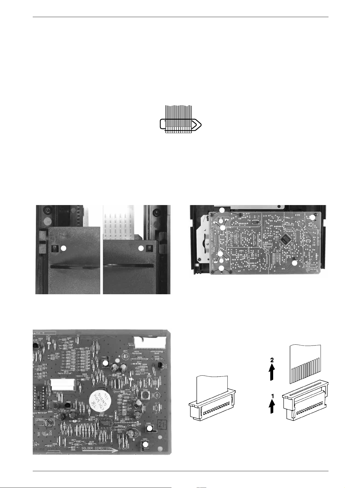
3. Laufwerk zerlegen
- Laufwerk ausbauen (Kap. 2).
- Flexprintstecker M (Fig. 5) öffnen.
- 2 Schrauben N (Fig. 5) herausschrauben und die Leiterplatte
abnehmen.
- Schublade bis zum Anschlag herausziehen.
- Die 2 Rastnasen O (Fig. 6) ausrasten, Schublade ganz herausziehen und nach oben herausnehmen.
4. CD-Leiterplatte ausbauen
- Laufwerk zerlegen (Kap. 3).
- Die 4 Lötstellen P und Q (Fig. 7) der Motoren auflöten.
- Die 6 Schrauben R (Fig. 7) herausschrauben und die Leiterplatte
abnehmen.
- Steckverbinder öffnen.
Vor dem Öffnen des Flexprint-Steckers eine metallene
Büroklammer über die Flexprint-Leitung schieben.
Beim Herausziehen der Flexprint-Leitung diese dann
nach unten über die Kontakte schieben (MOS-Bauteile)!
- Beim Wiedereinbau der Leiterplatte auf die 3 Schalter S (Fig. 8)
achten!
- Undo 2 screws K (Fig. 3) and take off the drive to the rear. When
mounting the drive take care of correct fitting of the connections L.
3. Disassembling the CD Drive
- Remove the drive (para 2).
- Open flexprint connector M (Fig. 5).
- Undo 2 screws N (Fig. 5) and remove the PCB.
- Open drawer until the stop.
- Unhook two catches O (Fig. 6), pull out drawer and take it off.
4. Remove CD PCB
- Disassemble CD drive (para 3).
Unsolder the motor solder pads P and Q (Fig. 7).
Undo 6 screws R (Fig. 7) and take off the PCB.
Open connections.
Before opening the flexprint connector, put a metal paper clip
Fig. 6
Fig. 8
Fig. 7
R
R
P
O O
Q
R
R
Öffnen eines Flexprint-Steckers
Opening a flexprint connector
S
S
S
GRUNDIG Service 1 - 5
Page 6

Allgemeiner Teil / General Section M 100-CDC
5. Pick-Up-Einheit ausbauen
- CD-Leiterplatte ausbauen (Kap. 4).
- 2 Schrauben T (Fig. 9) herausschrauben und die Halterungen U
abnehmen.
- Durch Drehen am Zahnrad V (Fig. 10) den Drehteller in eine
Position zwischen 2 Disks bringen.
- Die Pick-Up-Einheit kann jetzt einfach herausgenommen werden.
6. Schubladenantrieb ausbauen
- Laufwerk ausbauen (Kap. 3).
- 4 Schrauben W (Fig. 12) herausschrauben und Antriebsmechanik
herausnehmen.
7. Drehtellerantrieb ausbauen
- Pick-Up-Einheit ausbauen (Kap. 5).
- Durch Drehen am Zahnrad V (Fig. 10) den Drehteller in "PLAY"Position bringen (Fig. 11).
- Schraube X (Fig. 11) herausschrauben und Drehteller abnehmen.
- 6 Schrauben Y (Fig. 12) herausschrauben und Antriebsmechanik
herausnehmen.
Fig. 9
on the flexprint. When pulling out the flexprint, push the paper
clip over the contacts (MOS components)!
- When mounting the PCB look for the 3 switches S (Fig. 8).
5. Remove the pick up unit
- Remove the CD PCB (para 4).
- Undo 2 screws T (Fig. 9) and remove the holders U.
- By turning the gear wheel V (Fig. 10) set the turntable to a position
between two discs.
- The pick up unit can now be taken off.
6. Remove the drive mechanism of the drawer
- Remove CD drive (para 3).
- Undo 4 screws W (Fig. 12) and remove drive mechanism.
Fig. 10
V
UU
T T
Fig. 11 Fig. 12
Y
W
Y
X
W
1 - 6 GRUNDIG Service
Page 7

M 100-CDC Allgemeiner Teil / General Section
8. Schubladenantrieb zerlegen
- Schubladenantrieb ausbauen (Kap. 6).
- Die Zahrräder können nach Abziehen der entsprechenden Scheiben A (Fig. 13) abgezogen werden.
9. Drehtellerantrieb zerlegen
- Drehtellerantrieb ausbauen (Kap. 7).
- Die Zahrräder können nach Abziehen der entsprechenden Scheiben B (Fig. 14) abgezogen werden.
- Die Exzenterscheibe C (Fig. 15) kann nach Herausschrauben der
Schraube D abgenommen werden.
- Bei der Montage der Exzenterscheibe das Zahnrad E in eine
Stellung bringen, so daß keine Zähne sichtbar sind (Fig. 16)! Die
Exzenterscheibe dann wie in Fig. 17 aufsetzen.
Fig. 13 Fig. 14
7. Remove the drive mechanism of the turntable
- Remove the pick up unit (para 5).
- By turning the gear wheel V (Fig. 10) set the turntable to "PLAY"
position (Fig. 11).
- Undo screw X (Fig. 11) and remove turntable.
- Undo 6 screws Y (Fig. 12) and remove drive mechanism.
8. Disassemble the drive mechanism of the drawer
- Remove the mechanism (para 6).
- After pulling of the washers A (Fig. 13) the corresponding gear
wheels can be removed.
9. Disassemble the drive mechanism of the turntable
- Remove the mechanism (para 7).
- After pulling of the washers B (Fig. 14) the corresponding gear
wheels can be removed.
- Undo screw D to remove the eccentric wheel C (Fig. 15).
- When mounting the eccentric wheel the gear wheel E must be
brought in a position so that no teeth can be seen (Fig. 16)! Put up
the eccentric wheel like in Fig. 17.
A
B
B
Fig. 15
C
Fig. 16 Fig. 17
D
E
GRUNDIG Service 1 - 7
Page 8

Allgemeiner Teil / General Section M 100-CDC
Einfetten
grease
die Nut einfetten
grease inside groove
auf der Oberseite einfetten
grease on top of rib
einfetten
grease
Oberfläche der 4 Rechtecke einfetten
grease on 4 rectangular surfaces
die Nuten einfetten
grease inside grooves
die Schieber einfetten
grease on slide
die 4 Nuten einfetten
grease on 4 profile groves
Oberfläche des Rings einfetten
grease on top of highest ring
einfetten
grease
Fett: Sach-Nr. 75988-002.36
Grease: Part No. 75988-002.36
einfetten
grease
einfetten
grease
Ersten und letzten Zahn einfetten
Grease on first and last tooth
Schmierplan
Lubricating Instructions
1 - 8 GRUNDIG Service
Page 9

M 100-CDC Allgemeiner Teil / General Section
GRUNDIG Service 1 - 9
Einleitung
Der M100-CDC ist ein HiFi 3-Disc Karussel CDWechsel mit hochleistungsfähigem DAC. Der
Wechsler ermöglicht bis zu 3.5 Stunden
ununterbrochene nicht wiederholte Musik.
• Während der Wiedergabe der ersten CD ist
es möglich, die CD-Schublade zu öffnen und
die anderen beiden CDs auszutauschen, ohne
die Wiedergabe der ersten zu unterbrechen.
• Der 40 Titel Programmspeicher zusammen mit
der Tape Edit-Funktion erlauben leichtes
Kopieren des Inhalts von bis zu 3 CDs auf
Cassette, ohne extrem lange Leerpassagen
oder am Bandende abgeschnittene Stücke.
•
Die solide, 3mm dicke Aluminiumfront bietet ein
resistentes und langlebiges Gehäuse für das Gerät.
• Die RC-BUS Verbindungen bieten über den
Verstärker oder Receiver die Möglichkeit, den
CD-Wechsler fernzubedienen. Dies ermöglicht
auch
eine automatische CD-Eingangswahl am
Verstärker beispielsweise beim Wiedergabestart.
Außerdem können komplizierte Funktionen wie
Kopieren von CD auf Cassette mit nur einem
Tastendruck ausgelöst werden
Wichtige Hinweise
CLASS 1 LASER PRODUCT
bedeutet, daß der Laser
wegen seines technischen
Aufbaus eigensicher ist, so
daß der maximal erlaubte Ausstrahlwert unter
keinen Umständen überschritten werden kann.
VORSICHT: Wenn andere als die hier spezifizierten Bedienungseinrichtungen benutzt oder andere
Verfahrensweisen ausgeführt werden, kann es zu
gefährlicher Strahlungsexposition kommen.
CLASS 1
LASER PRODUCT
EINLEITUNG
Hauptfunktionen Ihres CD-Wechslers
Funktionen, die über das Gerät gesteuert werden:
• CD Auswahl
• Abspielen einer CD
• Sukzessives Aufrufen der Titel mit den Tasten S
T
• Zufallswiedergabe und Wiederholfunktion
• 40 programmierbare Titel (3 CDs)
• Funktion Tape Edit
• Ausgestattet mit automatischer Eingangswahl
• Fernbedienbar über Verstärker oder Receiver
(RC-BUS)
Funktionen über Systemfernbedienung (geliefert mit
dem Verstärker M100 A, M100 ADPL oder mit dem
Receiver M100 R):
• Abspielen einer CD
• Direkte Auswahl eines Titels über die Ziffern 1...0
• Sukzessives Aufrufen der Titel über die Tasten S
T
• Umschalten der Anzeigen: verbleibende Spieldauer
des gerade spielenden Titels, verbleibende Spieldauer der gesamten CD, Gesamtspieldauer der
CD, abgelaufene Spieldauer des gerade
spielenden Titels
Allgemeines
• Um die CD aus ihrem Gehäuse zu nehmen,
fassen Sie sie mit dem
Zeigefinger in der
Mitte und dem
Daumen am Rand an.
• Berühren Sie die
Spielseite der CD
nicht mit den Fingern.
• Bewahren Sie die
CDs in ihrem Gehäuse auf. Legen Sie die CD
mit dem Etikett nach oben in das Gehäuse und
drücken Sie leicht auf die Mitte.
• Die CDs niemals längere Zeit direkter
Sonneneinstrahlung aussetzen oder in der
Nähe einer Wärmequelle, z.B. einem
Heizkörper, aufstellen.
Wartung der CD's
• Niemals auf die bedruckte CD-Seite schreiben
(Label-Seite).
• Keine Aufkleber auf der CD anbringen.
• Die glänzende Oberfläche der CD sauberhalten.
• Benutzen Sie zum
Reinigen ein fusselfreies Tuch und
wischen Sie immer in
einer geraden Linie
von der CD-Mitte
nach außen.
• Verwenden Sie zum Reinigen einer CD
niemals weder Reinigungsmittel für
herkömmliche Schallplatten noch Lösungs- oder
Scheuermittel.
6
.
O
Y
E
M
I C
A
N
T
O
(
H
e
a
r
M
y
V
o
i
c
e
)
7
.
D
O
N
'
T
W
A
N
N
A
L
O
S
E
Y
O
U
8
.
G
E
T
O
N
Y
O
U
R
F
E
E
T
9
.
Y
O
U
R
L
O
V
E
IS
B
E
D
F
O
R
M
E
1
0
.
C
U
T
S
B
O
T
H
W
A
Y
S
1
1
.
O
Y
E
M
I
C
A
N
T
O
(
S
p
a
n
is
h
V
e
r
s
io
n
)
1
2
.
S
I
V
O
Y
A
P
E
R
D
E
R
T
E
E
P
C
4
6
5
1
4
5
2
BIEM/STEMRA
S
T
E
R
E
O
A
ll rig
h
ts
o
f th
e
p
ro
d
u
c
e
r a
n
d
o
f th
e
o
w
n
e
r o
f th
e
rec
o
rd
e
d
w
o
rk
res
e
rv
e
d
. U
n
a
u
th
o
rise
d
c
o
p
y
in
g
,
p
u
b
lic
p
e
rfo
rm
a
n
c
e
, b
ro
a
d
c
a
s
tin
g
, h
irin
g
o
r re
n
ta
l o
f th
is
re
c
o
rd
in
g
p
ro
h
ib
ited
. M
a
d
e
in
A
u
s
tria
1
.
A
Y
,
A
Y
,
I
2
.
H
E
R
E
W
E
A
R
E
3
.
S
A
Y
4
.
T
H
IN
K
A
B
O
U
T
Y
O
U
N
O
W
5
.
N
O
T
H
IN
' N
E
W
C
O
M
P
A
C
T
D
I
G
I
T
A
L
A
U
D
I
O
1
2
Aufstellen
• Wollen Sie Ihren CD-Wechsler in Regalwänden,
Schränken, etc. aufstellen, sorgen Sie bitte für
ausreichende Belüftung des Gerätes. Ein Freiraum
von mindestens 3 cm seitlich und oberhalb der
Anlage sowie 5 cm an der Rückseite sind
empfehlenswert.
• Verlegen Sie Netzkabel möglichst entfernt von
den Tonsignal-Leitungen, um störende
Einstrahlungen zu vermeiden.
• Achten Sie beim Anschließen auf die Kennzeichnungen der Leitungen bzw. Buchsen- oder Rückwandbeschriftungen, um ein Vertauschen der Anschlüsse
zu vermeiden. Ein Verpolen der Anschlüsse kann
den Klangeindruck erheblich beeinträchtigen.
Netzanschluß
•
Schließen Sie Ihr Gerät nur an Wechselspannung
230V~, 50/60 Hz an. Das Typenschild
befindet sich auf der Rückseite des Geräts.
• Wollen Sie Ihr Gerät zentral über einen
Verstärker dieser Serie einschalten und über die
System-Fernbedienung ausschalten, schließen Sie
das Gerät an einen der drei WechselspannungsAusgänge (AC OUTLETS) des Verstärkers an. Um
diese Funktion zu verwenden, stellen Sie sicher,
daß die Power-Taste des CD-Wechslers in
Position “ON” steht. Der Netzschalter des
Verstärkers dient dann als Zentralschalter.
INSTALLATION
230 V ~
50/60 Hz
byby
RC-BUS
230 V
~
50/60 Hz
L
R
RC-BUS
PHONO
PHONO
L
R
230 V
~
50/60 Hz
SPEAKERS A OR B – 4 TO 8/16
~
SWITCHED TOTAL 100W
L
R
L
R
SPEAKERS A AND B – 8 TO 16
SPEAKERS A OR B – 4 TO 8/16
SPEAKERS A AND B – 8 TO 16
–
+
–
+
ABA
B
–
+
–
+
TAPE
TAPE
ININOUT
OUT
AUX
AUX
ININOUT
OUT
TUNER
TUNERCDCD
M 100 A
M 100 CDC
byby
MAINS ~
230 V ~
50/60 Hz
ANALOG
OUTPUT
DIGITAL
OUTPUT
RC-BUS
RC-BUS
ANALOG
OUTPUT
L
R
DIGITAL
OUTPUT
Wichtig: Alle Geräte ausschalten, bevor
irgendwelche Verbindungen hergestellt werden.
Anschluß am Verstärker
Schließen Sie Ihren CD-Wechsler an die entsprechenden
Eingangs-Buchsen CD des Verstärkers an.
• Verbinden Sie dazu die Buchsen ANALOG
OUTPUT mit den Buchsen CD des Verstärkers.
Achten Sie beim Anschließen der Verbindungskabel auf die richtige Zuordnung der Stereokanäle: L = linker Kanal (weiß)
R = rechter Kanal (rot).
•
Verbinden Sie die Buchse DIGITAL OUTPUT mit
einem digitalen Eingang (falls vorhanden) Ihre
s
Verstärkers, Receivers oder digitalen Recorders.
Möchten Sie Ihren CD-Wechsler über den
Verstärker fernbedienen, muß die Innerverbindung
über die RC-BUS-Kabel gegeben sein.
• Verbinden Sie
RC-BUS
-Buchsen miteinander,
wie unten angezeigt:
byby
ANALOG
OUTPUT
RC-BUS
230 V
~
50/60 Hz
L
R
FM 75
AM/LOOP
AM/LOOP
ANTENNA
ANALOG
OUTPUT
RC-BUS
L
R
FM 75
ANTENNA
230 V
~
50/60 Hz
byby
RC-BUS
230 V
~
50/60 Hz
L
R
RC-BUS
PHONO
PHONO
L
R
230 V
~
50/60 Hz
SPEAKERS A OR B – 4 TO 8/16
~
SWITCHED TOTAL 100W
L
R
L
R
SPEAKERS A AND B – 8 TO 16
SPEAKERS A OR B – 4 TO 8/16
SPEAKERS A AND B – 8 TO 16
–
+
–
+
ABA
B
–
+
–
+
TAPE
TAPE
ININOUT
OUT
AUX
AUX
ININOUT
OUT
TUNER
TUNERCDCD
M 100 A
RC-BUS
M 100 T
M 100 CF
byby
230 V
~
50/60 Hz
230 V
~
50/60 Hz
LINE
OUT
RC-BUS
L
R
LINE
IN
M 100 CDC
byby
230 V
~
50/60 Hz
230 V
~
50/60 Hz
DIGITAL
OUTPUT
RC-BUS
ANALOG
OUTPUT
L
R
Vorderseite des CD-Wechslers
POWER Dieser Schalter wird zum Ein- und Ausschalten des Geräts verwendet.
DISC Mit dieser Taste können Sie CD 1, 2 und 3 auswählen.
ST
Mit diesen Tasten springen Sie in der Titelreihenfolge vorwärts oder
rückwärts oder starten den Suchlauf vorwärts oder rückwärts.
9 STOP Mit dieser Taste beenden Sie alle Funktionen.
PLAY 2
Diese Taste wird zum Starten oder erneuten Starten der Wiedergabe verwendet.
/ Mit dieser Taste öffnen und schließen Sie die CD-Schublade.
;
Mit dieser Taste unterbrechen Sie die Wiedergabe kurzzeitig (PAUSE), ohne
daß Geräteeinstellungen verändert werden.Wollen Sie mit der Wiedergabe
fortfahren, drücken Sie die Taste ; erneut.
MEMORY
Hiermit rufen Sie den Programmiermodus auf oder speichern einzelne Tracks.
EDIT Mit dieser Taste passen Sie die Spielzeit der CD an die verwendete
Leercassette an.
MODE Mit dieser Taste wählen Sie die verschiedenen Wiedergabefunktionen:
SHUFFLE –> REPEAT –> SHUFFLE REPEAT –> normale Wiedergabe –>
SHUFFLE –> usw.
CANCEL Hiermit löschen Sie einzelne Titel (Tracks) aus Ihrem Programm oder das
ganze Programm.
BEDIENELEMENTE
Ein- und Ausschalten
• Wollen Sie das Gerät ein- oder ausschalten,
drücken Sie den Netz-Schalter POWER
(einrasten). Die Betriebsanzeige, eine rote
Leuchtdiode in der Mitte des Einschalt-knopfes, informiert Sie über den
Schaltzustand: gedrückt: EIN
ausgerastet: AUS.
– Nach dem Einschalten liest das Gerät den
Inhalt der CD, die im Karussel der CD-Schublade in das erste Fach eingelegt wurde.
– Information über Anzahl der Stücke, Gesamt-
speilzeit, usw. wird im Display angezeigt.
– Befindet sich keine CD in Fach 1 sucht das
Gerät nach einer CD in Fach 2. Wird auch hier
keine CD gefunden, geht es auf Fach 3 über.
– Wenn in keinem der Fächer einer CD gefun-
den wird, erscheint die Nachricht ‘NO DISC’
eine Sekunde lang im Display; anschließend
‘–:– –’.
– Nach dem Einschalten ist das Gerät immer im
STOP-Modus.
• Wollen Sie das Gerät ausschalten, drücken
Sie den Netz-Schalter POWER nochmals
(ausrasten).
Automatische Eingangswahl
Die RC-BUS-Verbindung dieser Produktreihe
ermöglicht dem Verstärker, unter anderem, die
Auswahl der entsprechenden Signalquelle, wenn
das Gerät dieser Quelle zu spielen beginnt.
Dies betrifft auch den CD-Wechsler:
• Betätigen Sie am CD-Wechsler eine der
Tasten B, ;, MODE, S oder T, wählt
der Verstärker automatisch den Eingang CD.
Diese Funktion ermöglicht es auch, die Funktion
CD COPY durch Drücken von nur einer Taste
auszulösen (siehe Seite 10).
by
by
M100-CDC
M100-CDC
BITSTREAM
BITSTREAM
POWERPOWER
STOP
;
∞§
92
MEMORY CANCEL
EDIT MODE
MEMORY
DISC
DISC
CANCEL
EDIT MODE
MEMORY
CANCEL
POWER DISC
EDIT MODE
∞
PLAYSTOP
;
∞§
92
PLAY
;
92
§
STOP PLAY
/
3
1
2
PROGRAM
6543 D1
16
SHUFFLE
REPEAT ABREMAIN
TOTAL
1 2 3
CD einlegen
• Mit / öffnen Sie die CD-Schublade.
• Legen Sie eine CD in das linke und rechte Fach
ein, so daß die bedruckte Seite (Labelseite) nach
oben zeigt.
• Zum Einlegen der dritten CD zuerst die Taste
DISC drücken.
– Das CD-Wechsler-Karussel dreht sich, bis sich
das leere Fach links befindet und eine CD
eingelegt werden kann.
• Legen Sie CD-Singles (8 cm) in die Vertiefung der
Schublade.
• Drücken Sie / erneut. Die Schublade fährt ein.
• Sie können die Schublade auch manuell
zuschieben.
–
Nachdem die Schublade eingefahren ist, liest das
Gerät das Inhaltsverzeichnis der CD, die zuerst in
das rechte Fach eingelegt wurde.
– Dort sind Informationen über Titelanzahl, Spiel-
dauer, etc.
gespeichert. Diese werden im Display
angezeigt.
– Befindet sich keine CD im ersten Fach sucht das
Gerät nach einer CD im zweiten Fach. Wird auch
hier
keine CD gefunden, geht es auf dem dritten
Fach über.
– Wenn in keinem der Fächer einer CD gefunden
wird, erscheint die Nachricht ‘NO DISC’ eine
Sekunde lang im Display; anschließend ‘–:– –’.
ABSPIELEN
Abspielen einer CD
• Drücken Sie PLAY B, um die Wiedergabe zu
starten.
– Das Display zeigt die Nummer des aktuellen
Titels (Track), sowie die abgelaufene Spieldauer
(relative Spielzeit) an.
• Drücken Sie PLAY B erneut, wird das aktuelle
Stück wiederholt (REPLAY-Funktion).
• Wollen Sie die Wiedergabe unterbrechen, ohne
daß Geräteeinstellungen verändert werden,
drücken Sie die Taste ;.
• Wollen Sie mit der Wiedergabe fortfahren,
drücken Sie die Taste ; oder PLAY B erneut.
• Wird das Ende der ersten CD erreicht, sucht das
Gerät automatisch nach der nachfolgenden CD
und fährt mit der Wiedergabe fort.
• Um die Wiedergabe zu beenden, drücken Sie
die Taste 9 STOP.
• Während der Wiedergabe können Sie die CDSchublade öffnen und zwei CDs austauschen,
die Wiedergabe der dritten CD (im mittleren CDFach) wird nicht unterbrochen.
129 D1
1
123
006 D1
1
123
4341 D1
12
TOTAL
123
by
by
M100-CDC
M100-CDC
STOP
∞§
92
DISC
DISC
PLAYSTOP
∞§
92
PLAY
2
3
BITSTREAM
BITSTREAM
3
1
2
Bedienhinweise Hinweis: Dieses Kapitel enthält Auszüge aus der Bedienungsanleitung. Weitergehende Informationen entnehmen Sie
bitte der gerätespezifischen Bedienungsanleitung, deren Sachnummer Sie in der entsprechenden Ersatzteilliste finden.
Page 10

Allgemeiner Teil / General Section M 100-CDC
1 - 10 GRUNDIG Service
Titelsprung (NEXT/PREVIOUS)
• Drücken Sie die Taste T, so wird an den
Anfang des nächsten Stückes in der Titelreihenfolge gesprungen; mit der Taste S an den
Beginn des vorherigen Stückes (PREVIOUS).
• Betätigen Sie die Taste aus STOP heraus,
können Sie gezielt ein bestimmtes Stück
anwählen.
– Die Wiedergabe beginnt sofort.
Schneller Suchlauf
• Halten Sie die Taste S oder T gedrückt,
starten Sie den schnellen Suchlauf in die
entsprechende Richtung.
– Während des Suchlaufes können Sie mithören.
– Nach ca. 5 Sekunden wird das Gerät
stummgeschaltet.
ABSPIELEN
➥
➥
➥
➥
131 D1
4
123
138 D1
4
REPEAT
123
005 D2
7
SHUFFLE
1 23
012 D2
7
SHUFFLE
REPEAT
1 23
Funktion REPEAT und SHUFFLE
• Durch mehrmaliges Drücken von der Taste
MODE können Sie nacheinander die
Wiedergabefunktionen abrufen
:
REPEAT:
Die REPEAT-Funktion erlaubt es Ihnen, alle CDs zu
wiederholen (oder Ihr Programm).
– Das Display zeigt REPEAT.
Um die folgenden Funktionen für alle drei CDs
einsetzen zu können, ist es notwendig, den CDWechsler alle drei CDs, die in das Fach
eingelegt wurden, “lesen” zu lassen.
• Drücken Sie DISC, wenn die Schublade
geschlossen ist. Das Karussel dreht sich und
der Inhalt der mittleren CD wird gelesen und
im Display angezeigt.
• Wiederholen Sie diese Vorgehensweise bis
alle CDs gelesen wurden.
SHUFFLE:
Alle Titel der eingelegten CDs werden in zufälliger
Reihenfolge abgespielt bis jeder Titel einmal
gespielt wurde.
– Das Display zeigt SHUFFLE.
SHUFFLE REPEAT:
Alle Titel der eingelegten CDs werden wiederholt
in zufälliger Reihenfolge abgespielt, bis Sie diesen
Modus wieder verlassen
.
– Das Display zeigt SHUFFLE REPEAT.
– Alle Bedienfunktionen bleiben, wie bei
normaler Wiedergabe, erhalten.
– Mit den Tasten STkönnen Sie den
nächsten oder vorhergehenden willkürlichen
Titel wählen.
• Deaktivieren Sie alle Funktionen durch
mehrmaliges Drücken von MODE.
• Die Funktion wird auch beendet, wenn Sie die
Taste STOP 9 oder / drücken.
PROGRAMM-BETRIEB
Sie können max. 40 Titel auf bis zu 3 CDs programmieren.
Die Reihenfolge der Programmplätze bestimmt die Reihenfolge beim Abspielen. Jeder Titel
läßt sich mehrfach speichern. Sie können ein Programm
im STOP- oder PLAY-Betrieb eingeben.
Um ein Programm bestehend aus Stücken von allen
CDs zusammenstellen zu können, lassen Sie den
CD-Wechsler erst alle eingelegten CDs lesen.
•
Drücken Sie mehrmals DISC, wenn die Schublade
geschlossen ist, bis alle CDs gelesen wurden.
Programmieren
• Drücken Sie
MEMORY
. Jetzt haben Sie den
PROGRAM-Modus angewählt.
– PROGRAM blinkt im Display.
• Drücken Sie DISC um die gewünschte CD zu
selektieren.
• Wählen Sie mit S und T das erste Stück
an, das Sie in Ihr Programm aufnehmen wollen.
– Die Track-Nummer erscheint rechts im Display.
– Das Display zeigt Ihnen die Zeit an, welche die
Gesamtzeit Ihres Programms sein wird, wenn Sie
den ausgewählten Titel abspeichern. Auf diese
Weise können Sie sehr einfach nach Titeln suchen,
die innerhalb einer gewünschten Gesamtzeit Ihr
Programm darstellen (z. B. für Aufnahmezwecke).
Siehe auch Funktion TAPE EDIT.
• Drücken Sie
MEMORY
, wird das Stück in Ihr
Programm übernommen.
– 1 erscheint unter der PROGRAM-Anzeige und ein
P erscheint hinter der Titelnummer.
• Wählen Sie den nächsten Titel, den Sie Ihrem
Programm hinzufügen möchten. Speichern Sie mit
MEMORY.
– 2 erscheint unter der PROGRAM-Anzeige, die
Gesamtzeit wird aktualisiert und die Titelnummer
wird mit einem P markiert.
• Sie beenden das Programmieren, wenn Sie die
Taste 9 STOP, ; oder PLAYB drücken.
PROGRAM
716 5P
2
13
2
PROGRAM
308 3P
1
123
ERASED
13
2
PROGRAM
716 5
1
13
2
PROGRAM
229 1
0
123
PROGRAM
006 D1
2
13
2
Kontrollieren des Programmes
• Taste MEMORY mindestens 2 Sekunden (im
PROGRAM-Modus) drücken .
Die Kontrolle (Anzeige) der bisher programmierten Titel beginnt.
Wiedergeben des Programmes
• Drücken Sie die Taste PLAY B, beginnt die
Wiedergabe Ihres Programmes.
– Sie können alle Funktionen des Wiedergabe-
betriebes ausführen
Löschen eines Titels aus dem Programm
• Möchten Sie nur einen Titel löschen, wählen Sie
den Titel mit den Tasten S oder T an (im
PROGRAM-Modus).
• Drücken Sie die Taste CANCEL.
– Der Titel ist jetzt gelöscht und das P hinter der
Titelnummer verschwindet. Die Gesamtzeit des
Programms wird aktualisiert.
Löschen des Programmes
• Sie löschen das gesamte Programm, indem Sie
während der Wiedergabe oder im Stop-Modus
die Taste CANCEL drücken.
Das Display zeigt zuerst ERASED und danach
wieder die Anzahl von Titeln und die Gesamtspieldauer der CD, die zuletzt ausgewählt war.
•
Öffnen Sie die Schublade (/) oder schalten Sie das
Gerät aus, wird das Programm ebenfalls gelöscht.
Kopieren von CD auf Cassette
Die CD-COPY-Funktion startet den CD-Wechsler und
das Cassettendeck gleichzeitig.
Zusätzlich wird gewährleistet, daß die Aufnahme
richtig ausgeführt wird, ohne den Beginn
abzuschneiden.
Bevor Sie die CD-Kopierfunktion starten:
• Es muß sich eine bespielbare Cassette im
Cassettendeck befinden.
• Wählen Sie am CD-Wechsler die gewünschten
Tracks.
• Stellen Sie sicher, daß die Audiokabel richtig mit
dem Verstärker verbunden sind.
• Beide Geräte müssen über die RC-BUS-Leitung
miteinander verbunden sein.
• Spulen Sie zur Vorbereitung die Cassette an die
vorgesehene Bandstelle.
Starten der CD-Kopierfunktion:
•
Drücken Sie jetzt CD-COPY auf dem Cassettendeck.
– Das Cassettendeck schaltet auf RECORD PAUSE.
• Wählen Sie die Cassetten-Seite auf der Sie
aufnehmen möchten sowie Einzel- å oder
Doppelseitenbespielung ∂.
• Zum Starten des Überspielvorganges drücken Sie
CD COPY noch einmal.
– Beginnen Sie die Aufnahme am Anfang des
Cassettenbandes, läuft Ihr Cassettendeck an, um
ca. 6 Sekunden Vorspannband abzuspulen
.
Der CD-Wechsler ist zunächst auf Pause gestellt
und beginnt nach 6 Sekunden die Wiedergabe.
–
Falls Sie nicht am Anfang der Cassettenseite sind,
wird eine 4-Sekunden Leeraufnahme eingefügt.
Der CD-Wechsler ist zunächst auf Pause gestellt
und beginnt nach 4 Sekunden die Wiedergabe.
– Während des Überspielvorganges können Sie
nur die Tasten 9 STOP oder / OPEN/CLOSE
betätigen. Alle anderen Funktionen sind gesperrt.
Wenn am Verstärker eine andere Signalquelle gewählt wird, wird der Kopiervorgang abgebrochen.
CD COPY TAPE EDIT
➥
➥
➥
C46
123
C60
123
C90
1 23
4454 D1
12
1 23
TOTAL
–
Beendet der CD-Wechsler die Wiedergabe als erstes,
sendet er ein entsprechendes Kommando an das
Cassettendeck, die Aufnahme wird gestoppt.
– Ist die Cassettenseite als Erstes zu Ende, schaltet
der CD-Wechsler in PAUSE-Modus.
CD COPY ohne voreingestellte Aufnahmedauer
Wenn am Cassettendeck der Reverse-modus ∂ ge
wählt ist und das Bandende während eines laufenden Titels erreicht wird, wiederholt der CD-Wechsler
diesen Titel am Anfang der zweiten Cassettenseite
CD COPY mit voreingestellte Aufnahmedauer
Wenn die Aufnahmedauer der Cassette mit EDIT
(siehe unten) eingegeben worden ist, zeigt das Display
an, welche Titel auf eine Cassettenseite passen.
Nach dem letzten Titel wird eine Leerstelle eingefügt
und die restlichen Titel werden auf der
zweiten Seite
aufgenommen (wenn ∂ selektiert ist).
Funktion TAPE EDIT
Die Funktion EDIT gewährleistet automatische
Anpassung des Programms oder der CD-Länge an
die Länge der Cassette
. Die Funktion gemeinsam mit
CD-COPY stellt sicher, daß keine Titel während des
Kopierens in der Mitte enden.
• Drücken Sie die Taste EDIT, rufen Sie der Reihe
nach die Angaben C 46, C 60, C 90, C 100,
C 110, C 120 auf.
• Wählen Sie die entsprechende Spieldauer der
Cassette.
– Nach kurzer Zeit zeigt Ihnen das Gerät die
Gesamtspieldauer und welche Titel auf die erste
Seite der Cassette überspielt werden.
Durch Benutzen der Taste
TXT/6
auf der Fernbedienung können Sie sich anzeigen lassen,
welche Titel auf die zweite Seite kopiert werden.
• Starten Sie die Funktion CD COPY.
– Die erste Seite wird bespielt. Danach zeigt das
Display die Verteilung der Titel für die nächste Seite.
•
Diese Funktion können Sie auch in Verbindung mit
einem von Ihnen erstellten Programm ausführen.
Diese Fernbedienung ist Teil des Lieferumfanges
des Verstärkers M100 A, M100 ADPL oder des
Receivers M100 R.
Folgende CD-Funktionen können über die
Fernbedienung ausgeführt werden:
Stellen Sie sicher, daß der Schieber HIFI TV/VCR auf Position HIFI steht.
Die Tasten 9, B, ; , S and T haben die
gleiche
Funktion wie die entsprechenden Tasten
am Wechsler.
SYSTEMFERNBEDIENUNG
➥
➥
➥
➥
005 D1
1
123
224 D1
1
123
4334 D1
1
1 23
4341 D1
12
1 23
REMAIN
TOTAL
REMAIN
TOTAL
1 2 3 4 5
6 7 8 9 0
STATION
VOLUME
SAT
TV
TAPE 1 2
CD/disc
TUNER/pty VCR
SAT
TV
8
3
Z
T
1
A/V REMOTE CONTROL-URC1
1
E
a
P
P
P
HIFI TV/VCR
HIFI
88
TXT/6
P
P
P
AV
Install
–
+
CENTRE
SURROUND
REAR
$
#
2
RECORD
1 2 3 4 5
6 7 9 0
TXT/6
8
CD/disc
3
Z
T
E
2
Auswahl des CD-Wechslers:
• Drücken Sie die Taste CD/disc.
Auswahl der CDs:
• Drücken Sie die Taste CD/disc nachdem die Quelle
CD ausgewählt wurde.
Auswahl der Titel:
• Drücken Sie die Tasten S und T, um die Titel
nacheinander aufzurufen.
• Geben Sie die Titelnummer mit den Zifferntasten
1...0 direkt ein:
• Bei einstelligen Nummern betätigen Sie die entsprechende Zifferntaste nur kurz.
• Um zweistellige Nummern zu speichern, drücken
Sie die erste Ziffer eine längere Zeit, bis diese auf
die linke Seite des Displays springt: 1-.
• Geben Sie danach die Einerstelle ein.
– Es ist nicht möglich, eine Nummer einzufügen, die
nicht auf der CD existiert.
Umschalten der Anzeigen
• Taste TXT/6 drücken, wenn die verbleibende
Spieldauer des gerade spielenden Titels angezeigt
werden soll (nur während der Wiedergabe).
• Erneut Taste TXT/6 drücken, wenn die verbleibende
Spieldauer der gesamten CD (oder CD-Programm)
angezeigt werden soll.
• Erneut Taste TXT/6 drücken, wenn die Gesamtspieldauer der CD angezeigt werden soll.
• Erneut Taste TXT/6 drücken, um zur Anzeige der
abgelaufenen Spieldauer des gerade spielenden
Titels zurückzukehren.
• Durch Drücken der Taste TXT/
6 während der EDIT-
Funktion, springen Sie zwischen der Anzeige der
Gesamtspielzeit und welche Titel auf die erste bzw.
zweite Seite aufgenommen werden sollen.
Page 11

M 100-CDC Allgemeiner Teil / General Section
GRUNDIG Service 1 - 11
Operating Hints Note: This chapter contains excerpts from the operating instructions. For further particulars please refer to the
appropriate user instructions the part number of which is indicated in the relevant spare parts list.
Introduction
The M100-CDC is a HIFI carrousel type 3-disc CDchanger with high performance DAC, allowing up
to 3.5 hours of non-stop unrepeated music.
• During playback of one disc, it is possible to
open the CD compartment and change the
others without interrupting playback.
• The 40 title program memory combined with
the Tape Edit function, allow easy copying of
the contents of up to 3 CD’s to cassettes
without cuts or blank passages between titles.
• The solid 3 mm thick aluminium front provides
a rigid and long lasting cabinet for the set.
• The RC-BUS connectors, a Grundig specific
control bus, allow that the CD player is remote
controlled via the amplifier or receiver and that
the amplifier automatically selects the CD
source when, for example, the set starts to play.
Also complicated procedures like copies
from
CD to tape are now done with the touch of
one key.
Warning
CLASS 1 LASER PRODUCT means that the laser´s
construction makes it inherently safe so that the
legally prescribed maximum permissible ratiation
values can never be exceeded.
CAUTION: Using any equipment or devices other
than those described and specified in these operating instructions, or tampering with the unit in any
way, can result in dangerous exposure to radiation.
CLASS 1
LASER PRODUCT
INTRODUCTION
Main features of your player
Functions which can be controlled via the unit:
• CD selection
• Playing a CD
• Calling up the tracks one after another with the
S T buttons.
• Shuffle and repeat modes
• 40 programmable tracks (in 3 discs)
• Tape edit function
• Changing of 2 discs during playback of the third.
• Equipped for automatic source selection
• Remote control via amplifier or receiver (RC-BUS).
Functions via the system remote control
(which is supplied with the amplifier M100 A or
M100 ADPL or receiver M100 R):
• Playing a CD
• Direct track selection with the numeric buttons 1...0:
• Calling up the tracks one after another with the
S T buttons.
• Switching the display indications: remaining track
time, remaining total time, total disc time, elapsed
playing time.
General information
• To remove a CD from its case, hold it on its
outside edge with the
index finger and
thumb.
• Do not touch the
surface of a CD with
your fingers.
• Always store a CD in
its case when it is not
being used.
• Place a CD in its case with the label facing up
and press down lightly.
• Do not leave CD's for any length of time in
direct sunlight or other places where high
temperatures may occur, such as in the vicinity
of heating apparaturs. Do not expose the CD's
to humidity or rain.
Caring for the CD's
•
Never write on the printed (label) side of a CD.
• Never attach adhesive labels of any kind to a
CD.
• You should always
keep the CD surfaces
clean.
• Wipe the top shiny
surface with a lint-free
cloth in a straight line
from the inside of the
CD to its outside
edge.
• Never use cleaning agents intended for
conventional LP's, including solvents or
abrasives, to clean a CD.
Setting up
•I
f you want to set up your CD changer on a shelf
,
in a cabinet or any other type of enclosure,
always ensure that sufficient ventilation is
available. An open space of at least 3 cm at the
sides and the top, and 5 cm at the back of your
system is required.
• Place the power supply cable as far as possible
from the sound signal lines in order to avoid
disturbing signal interference.
• When making connections, always note the
identification markings on the cables and sockets,
as well as those on the back of the unit, in order
to avoid improper connections. Improper
connections can considerably impair sound quality.
INSTALLATION
Power supply connection
• Only connect the unit to a 230V~, 50/60 Hz
a.c. power source.
The rating is found on the back of the unit.
• If you want to switch your unit on and off via an
amplifier from this series, or with the system
remote control, connect the mains plug of the CD
changer to one of the AC OUTLETS of your
amplifier. To use this capabilitiy, ensure that the
power switch of the CD changer is switched to
the ON position. The amplifier´s power switch
can then be used as the main switch for all the
units.
Note: Before making any connections, make
sure that all units are switched off.
Connection to the amplifier
Your CD changer should be connected to the
corresponding input sockets on the amplifier.
• Connect the ANALOG OUTPUT sockets to the
CD input sockets on the amplifier.
When connecting the cables, ensure the
proper arrangement of the stereo channels:
L = left channel (white).
R = right channel (red).
• Connect the socket DIGITAL OUTPUT with a
digital input (if available) of an amplifier,
receiver, or digital recorder.
If you would like to use your amplifier to switch on
and remotely
control your CD-player, the units
must be interconnected by the RC-BUS lines.
• Interconnect the
RC-BUS sockets of the units in
your system as shown below.
byby
ANALOG
OUTPUT
RC-BUS
230 V
~
50/60 Hz
L
R
FM 75
AM/LOOP
AM/LOOP
ANTENNA
ANALOG
OUTPUT
RC-BUS
L
R
FM 75
ANTENNA
230 V
~
50/60 Hz
byby
RC-BUS
230 V
~
50/60 Hz
L
R
RC-BUS
PHONO
PHONO
L
R
230 V
~
50/60 Hz
SPEAKERS A OR B – 4 TO 8/16
~
SWITCHED TOTAL 100W
L
R
L
R
SPEAKERS A AND B – 8 TO 16
SPEAKERS A OR B – 4 TO 8/16
SPEAKERS A AND B – 8 TO 16
–
+
–
+
ABA
B
–
+
–
+
TAPE
TAPE
ININOUT
OUT
AUX
AUX
ININOUT
OUT
TUNER
TUNERCDCD
M 100 A
RC-BUS
M 100 T
M 100 CF
byby
230 V
~
50/60 Hz
230 V
~
50/60 Hz
LINE
OUT
RC-BUS
L
R
LINE
IN
M 100 CDC
byby
230 V
~
50/60 Hz
230 V
~
50/60 Hz
DIGITAL
OUTPUT
RC-BUS
ANALOG
OUTPUT
L
R
230 V ~
50/60 Hz
byby
RC-BUS
230 V
~
50/60 Hz
L
R
RC-BUS
PHONO
PHONO
L
R
230 V
~
50/60 Hz
SPEAKERS A OR B – 4 TO 8/16
~
SWITCHED TOTAL 100W
L
R
L
R
SPEAKERS A AND B – 8 TO 16
SPEAKERS A OR B – 4 TO 8/16
SPEAKERS A AND B – 8 TO 16
–
+
–
+
ABA
B
–
+
–
+
TAPE
TAPE
ININOUT
OUT
AUX
AUX
ININOUT
OUT
TUNER
TUNERCDCD
M 100 A
M 100 CDC
byby
MAINS ~
230 V ~
50/60 Hz
ANALOG
OUTPUT
DIGITAL
OUTPUT
RC-BUS
RC-BUS
ANALOG
OUTPUT
L
R
DIGITAL
OUTPUT
Front of the CD player
POWER For switching the CD changer on and off.
DISC To turn the rotary CD tray in order to select disc 1, 2 or 3.
ST
To skip to next and previous tracks or to start forward or
backward search for a passage.
9 STOP To end all functions.
PLAY 2 To start or restart playback.
/ To open and close the CD compartment.
;
To briefly interrupt playback (PAUSE), without changing the unit settings.
Press once more to start playback again.
MEMORY To call up the programming mode or to save individual tracks.
EDIT To adjust the CD playing time to the length of the cassette you are
recording to.
MODE This is used to call up the different playing modes in the following order:
SHUFFLE –> REPEAT –> SHUFFLE REPEAT –> normal playback –>
SHUFFLE –> etc.
CANCEL This button is used to omit individual tracks from the programme or to
delete the complete programme.
OPERATING ELEMENTS
Switching on and off
• When you want to switch your CD changer on,
press the POWER button. The red light in the
middle of the button indicates that the unit is on.
button depressed: POWER ON
button not depressed: POWER OFF
–
After switching on, the unit reads the
contents of
the CD which is positioned in tray 1.
• Information on the number of tracks, playing
length, etc. is shown in the display.
• If there is no CD in tray 1, the unit looks for a
CD in tray 2. If also here no CD is found, it starts
looking for a CD in tray 3.
• If no CD is found in any of the trays, the
message ‘NO DISC’ appears during 1 second
and afterwards the display shows ‘–:– –’.
– After the unit has been switched on, it is always
in the STOP mode.
• When you want to switch the unit off, simply
press the POWER button again.
Automatic source selection
The RC-BUS of this series enables, among others,
that the amplifier automatically selects the
corresponding source if the respective unit starts to
play.
This applies also to this CD changer:
• If you press the B, ;, MODE, S or T
buttons on the CD changer, the amplifier
automatically selects the input CD.
This function also allows the CD COPY function to
be
carried out by pressing just one button. (see page
19).
by
by
M100-CDC
M100-CDC
BITSTREAM
BITSTREAM
POWERPOWER
STOP
;
∞§
92
MEMORY CANCEL
EDIT MODE
MEMORY
DISC
DISC
CANCEL
EDIT MODE
MEMORY
CANCEL
POWER DISC
EDIT MODE
∞
PLAYSTOP
;
∞§
92
PLAY
;
92
§
STOP PLAY
/
3
1
2
PROGRAM
6543 D1
16
SHUFFLE
REPEAT ABREMAIN
TOTAL
1 2 3
Inserting CD’s
• Open the CD compartment by pressing /
• Insert a CD with the printed side of the disc
facing up in the left and right tray.
• To insert a third CD press first DISC.
– The CD changer carrousel will rotate until the
empty tray is at the left hand side and ready for
loading.
• Place CD singles (8 cm) in the depression in the
compartment.
• Press / again. The compartment closes.
•
The CD compartment can also be closed by hand.
–
After the compartment has closed, the unit reads the
contents of the CD which was positioned first in
the right tray.
– Information on the number of tracks, playing
length, etc. is shown in the display.
• If there is no CD in the first tray , the unit looks for
a CD in the second tray. If also here no CD is
found, it starts looking for a CD in the third tray.
• If no CD is found in any of the trays, the message
‘NO DISC’ appears during 1 second and
afterwards the display shows ‘–:– –’.
PLAYBACK
129 D1
1
123
006 D1
1
123
4341 D1
12
TOTAL
123
by
by
M100-CDC
M100-CDC
STOP
∞§
92
DISC
DISC
PLAYSTOP
∞§
92
PLAY
2
3
BITSTREAM
BITSTREAM
3
1
2
CD playback
• Press PLAY B to start playback.
– The display shows the number of the CD, the
number the track being played as well as the
elapsed playing time (relative playing time).
• If you press PLAY B again, the running track
will be restarted (REPLAY function).
• If you want to interrupt playback without
changing the unit settings, press ;.
• If you want to continue with playback, press ; or
PLAY B once more.
• When the end of the first CD is reached, the unit
automatically starts looking for the next CD and
playback is continued.
• To stop playback, press 9 STOP.
• During playback you can open the CD compartment and change two CD’s while the third (in
the centre tray) continues to be played back.
2
,
g
in
y
p
tria
s
o
u
c
d
A
1
. A
e
Y
in
,
A
2
ris
Y
e
.
,
H
I
E
o
d
R
E
3
a
W
.
th
S
E
A
u
Y
A
4
R
a
. M
.
E
T
H
n
d
IN
5
K
.
N
A
ite
B
O
. U
O
T
H
U
d
ib
IN
T
Y
'
e
N
h
O
E
U
W
N
rv
ro
O
W
se
p
g
1
re
in
rk
rd
o
o
c
w
d
re
e
is
rd
o
f th
c
l o
re
e
ta
n
r re
r of th
o
e
g
n
E
w
P
C
irin
4
o
6
5
BIEM/STEMRA
1
e
4
, h
5
2
g
S
T
f th
E
R
tin
E
o
O
s
d
a
n
c
C
O
M
d
P
A
r a
C
a
T
e
ro
c
u
, b
d
D
I
G
I
e
T
A
ro
L
c
A
U
D
n
I
p
O
a
e
rm
f th
o
6
.
erfo
O
ts
Y
E
h
7
p
M
. D
I
C
O
A
N
lic
N
'
8
T
T
.
O
b
W
G
ll rig
E
(
A
H
u
T
N
e
9
A
O
N
a
.
r
A
p
N
Y
M
L
Y
O
y
O
O
U
S
R
U
V
1
E
0
L
R
o
.
i
F
Y
O
c
C
e
O
E
V
U
)
U
E
E
T
1
T
IS
S
1
B
.
B
O
O
Y
E
T
E
D
1
H
2
M
F
W
. S
O
I
A
C
R
I
V
Y
A
M
S
N
O
E
T
Y
O
A
(
P
S
p
E
a
R
n
D
is
E
h
R
V
T
e
E
r
s
io
n
)
Page 12

Allgemeiner Teil / General Section M 100-CDC
1 - 12 GRUNDIG Service
Next/previous track
• By briefly pressing T you can skip to the
beginning of the next track in the track
sequence,
and by pressing S you can skip
to
the beginning of the preceding track.
•
While in STOP mode you can select a certain
track.
– Playback begins immediately.
Fast search
• By keeping S or T pressed, you activate
the fast search in the corresponding direction.
– During the fast search procedure you can listen
to the tracks.
– After approx. 5 seconds the unit´s mute
function is activated.
PLAYBACK
➥
➥
➥
➥
131 D1
4
123
138 D1
4
REPEAT
123
005 D2
7
SHUFFLE
1 23
012 D2
7
SHUFFLE
REPEAT
1 23
REPEAT and SHUFFLE function
•
By pressing the MODE button, you can successively
activate the following playing modes:
REPEAT:
The repeat function allows you to repeat all CD’s
(or your CD programme).
– The display shows REPEAT.
In order to have the following functions performed
on all three CD’s, it is necessary to let the
changer ‘read’ all three CD’s inserted in the tray.
• Press DISC while the compartment is closed.
The carrousel will rotate and read the contents
of the CD in the centre tray. The information
will be shown on the display.
•
Repeat this procedure until all three CD’s are
read.
SHUFFLE:
The tracks on the loaded CD’s are played in
random
order until all of them have been played
once.
– The display shows SHUFFLE.
SHUFFLE REPEAT:
T
he tracks on the loaded CD’s are played
repeated
ly in random order until you leave this
mode.
– The display shows SHUFFLE REPEAT.
– All operating functions continue to function as
during normal playback.
– With the STbuttons you can select
next or previous random tracks.
• By pressing the MODE button again you go
back to normal playback.
• The different modes are also deactivated by
pressing STOP 9 or /.
You can store up to 40 tracks out of 3 CD’s to
create your own selection. The order of the
programmed tracks determines the order in which
they are played. Each track can be stored as often
as you like. You can enter a programme in the
STOP mode or in the PLAY mode.
In order to make a program consisting of tracks of
all three discs, you should let the changer ‘read’ all
three discs inserted in the CD compartment.
• Press, with the compartment closed, several times
the DISC button until all
three discs are read.
Programming
•
Press MEMORY to select the PROGRAM mode.
– PROGRAM starts flashing on the display
• Press DISC to select the CD from which you wish
to program.
• Select the first track you want to programme with
S and T.
–
The track number appears on the right of the display.
– The display shows the time which will be the total
time of your programme when you store the
selected track. In this way you can easily search
for tracks which fill in your program to a desired
total time (e.g. for recording purposes). See also
TAPE EDIT function.
•
Press MEMORY to store the track in your programme.
– 1 appears below the PROGRAM indication and
a P appears behind the track number.
•
Choose the next CD and track you wish to include
in your programme and press MEMORY to save it.
– 2 appears below the PROGRAM indication, the
playing time display is updated and the track
number is marked with a P.
• You can leave the programme mode by pressing
the 9 STOP, ; or PLAYB button.
PROGRAMMING
PROGRAM
716 5P
2
13
2
PROGRAM
308 3P
1
123
ERASED
13
2
PROGRAM
716 5
1
13
2
PROGRAM
229 1
0
123
PROGRAM
006 D1
2
13
2
Checking the programme
• Keep the MEMORY button pressed for at least 2
seconds while in the PROGRAM mode..
– The display starts showing all stored titles in the
programmed sequence.
Programme playback
• To play the programme you have created, press
PLAY B.
– All playback functions continue to function as
normal.
Deleting a track from a programme
• If you wish to delete individual tracks from your
programme, select the track with the S or
T buttons while in the PROGRAM mode.
• Press CANCEL.
– The track is now deleted from the programme.
and the P behind the tracknumber disappears.
The total time of your programme is updated.
Deleting the programme
• To delete the entire programme, press CANCEL
while in the STOP mode or during playback.
The display shows ERASED and then again the
total number of tracks and the total playing time
of the CD which was last playing.
• Opening the compartment (/) or shutting off the
unit also deletes the programme.
CD COPY TAPE EDIT
Copying from a CD to cassette
The CD-COPY function starts both CD changer and
cassette deck simultaneously.
In addition it automatically performs a number of
steps to start the recording properly without cutting
the start of any music piece.
Before you start the CD COPY function:
• There must be a non-protected cassette in the
cassette compartment
• The disc you wish to copy has to be in the CD
tray.
Optionally you can select the desired tracks.
• Make sure that the audio cables are correctly
connected to your amplifier
• Both units must be connected via RC bus lines.
• Prepare the cassette tape by winding to the
desired tape position.
Starting the CD COPY function
• Press CD-COPY on the cassette deck.
– The cassette deck will go to RECORD PAUSE.
• Select on the deck the tape side onto which you
want to record and single å or double ∂ sided
recording.
• To start copying, press CD COPY again.
–
If your are positioned at the beginning of a cassette
side, the cassette deck will start recording first in
order to take up approx. 6 seconds of tape leader.
The CD changer is first switched to pause and then
(after these 6 seconds) starts playing automatically.
– If you are not positioned at the beginning of a
tape side, the cassette deck will start recording 4
seconds of blank space.
The CD changer is first switched to pause and then
(after 4 seconds) starts playing automatically.
– During the recording procedure you can only use
the 9 STOP or / OPEN/CLOSE buttons on both
units. All other functions are deactivated.
If you change the source on the amplifier you will
also interrupt the copy.
➥
➥
➥
C46
123
C60
123
C90
1 23
4454 D1
12
1 23
TOTAL
–
If the CD changer is the first unit to stop playback,
it automatically sends a corresponding command
to the cassette deck, and recording is stopped.
– If the respective side of the cassette reaches the
end first, the CD changer switches to PAUSE mode.
CD COPY without a given tape length
If you have selected ∂ on the cassette deck and
the end of the tape is reached in the middle of a
track, the CD changer repeats that track from the
beginning on the second side.
CD COPY with a given tape length
If you have chosen the tape length with the EDIT
function (see below), the display shows which tracks
fit on one side of the cassete. A blank part will be
recorded after the last track and the following tracks
will be recorded on the second side of the cassette
(provided ∂ was selected).
TAPE EDIT function
The function EDIT enables automatic adaptation
of
programme or disc length to the cassette length.
This function used together with CD-COPY will
ensure that no tracks are cut off in the middle during
copying of the CD to the cassette.
• Press EDIT to call up the entries C 46, C 60, C
90, C 100, C 110, C 120 one after another.
• Select the corresponding length of the cassette.
– After a brief time the display will show you the
total playing time and which tracks will be
recorded onto the first side of the cassette.
Using the TXT/6 key on the remote control you can
see which tracks will be recorded on the second side.
• Start the CD COPY function.
– It starts to record on the first side. When it is
finished, the display shows the tracks that will be
recorded onto the other side.
• This function can also be used to record a
programme that you have saved.
This remote control is supplied with the
amplifiers M100 A, M100 ADPL or receiver
M100 R.
The following CD functions can be carried out
with the remote control:
Make sure that the slider HIFI - TV/VCR is set to
position HIFI
The buttons 9, B, ; , S and T have the
same functions as the corresponding ones on the
player.
SYSTEM REMOTE CONTROL
➥
➥
➥
➥
005 D1
1
123
224 D1
1
123
4334 D1
1
1 23
4341 D1
12
1 23
REMAIN
TOTAL
REMAIN
TOTAL
Selecting the source CD:
• Press the CD/disc button.
Selecting the CD’s:
• Press the CD/disc button after the source CD has
been selected.
Selecting tracks:
• Press the S and T buttons to call up the next
or previous tracks one after another.
• You can also directly select the tracks with the
numeric buttons 1...0:
• For one-place track numbers, press the
corresponding button only briefly.
• For two-place track numbers, first press the first digit
longer until this digit jumps to the left side of the
display: 1-.
• Then enter the second digit.
– It is not possible to enter a number that does not
exist on the CD.
Changing the display indication:
• Press TXT/6 and the display shows you the
remaining time of the current track (only possible
during playback).
• If you press TXT/
6 again, the total remaining time
on the CD (or CD program) is indicated..
• Pressing TXT/
6 once more indicates the total
playing time and the total number of tracks.
• When you press TXT/6 once more, the display
returns to showing the elapsed playing time of the
current track.
•
Using the TXT/6 key d
uring the EDIT function, you
can toggle between indication of the total playing
time and which tracks will be recorded onto the first
and second side of the cassette.
1 2 3 4 5
6 7 8 9 0
STATION
VOLUME
SAT
TV
TAPE 1 2
CD/disc
TUNER/pty VCR
SAT
TV
8
3
Z
T
1
A/V REMOTE CONTROL-URC1
1
E
a
P
P
P
HIFI TV/VCR
HIFI
88
TXT/6
P
P
P
AV
Install
–
+
CENTRE
SURROUND
REAR
$
#
2
RECORD
1 2 3 4 5
6 7 9 0
TXT/6
8
CD/disc
3
Z
T
E
2
Page 13

M 100-CDC Schaltpläne und Druckplattenabbildungen / Circuit Diagrams and Layout of PCBs M 100-CDC Schaltpläne und Druckplattenabbildungen / Circuit Diagrams and Layout of PCBs
Schaltpläne und Druckplattenabbildungen / Circuit Diagrams and Layout of PCBs
Verdrahtungsplan / Wiring Diagram
KEY TO CONNECTION
TYPE
CONNECTOR
TRAFO
59430-034.02
1
+5V
KEY1
P300
(CCC4)
P301
KEYBOARD
RIGHT
(59450-976.03)
(BURNDY)
+5V
KEY1
KEY2
P202
ONLED
+5V
1
(CCC4)
1
P400
KEYBOARD CENTER
(ZIF4)
(59450-976.02)
DISPLAY DRIVE BOARD
(59450-976.00)
1
COAX1
CINCH BOARD
(59450-976.04)
P109
(BURNDY)
1
+5V
GND
PLED
PD
VEE(-33V)
F2
F1
P200
(BURNDY)
P110
(BURNDY)
1
RC
RCGND
DATA
STROB
ACK
RESET
P201
HOLLESHOLLESHOLLES
(BURNDY)
CONTROL BOARD
(59450-960.00)
P103
COAX2
GND
RC
RCGND
L
GND
R
P600
(CCC8)
P108
1
(ZIF8)
15.54VAC
15.54VAC
20.54VAC
20.54VAC
4.5VAC
4.5VAC
P100
ZIF - ZERO INSERTION FORCE
CCC - CABLE CENTERING CASE
BURNDY - BOARD TO BOARD
P500
LED BOARD
(59450-976.06)
(ZIF4)
P203
(CCC4)
111
(BURNDY) (BURNDY) (BURNDY)
SHUFFLE REPEAT A B REMAIN TOTAL
PROGRAM ANTENNA CABLE
TUNED
P602
POWER SWITCH
BOARD
(59450-976.05)
1
COAX1
DISPLAY BOARD
(59450-978.00)
P207P206P205
2345671
KHZ
MHZ
COAX2
GND
LEFT
GND
RIGHT
+5V-CDC
GND
+9.1V
SW-INFO
STH-OUTPUT
SHR-CL
SICL
DATA
SILD
GND
PORE
OE-LATCH
1805
CDC BOARD
CLASS 1
50Hz/60Hz
230V~
MAINS
BN
BL
BN
BL
P601
LASER PRODUCT
11/09/96
GRUNDIG Service GRUNDIG Service2 - 1 2 - 2
Page 14

Schaltpläne und Druckplattenabbildungen / Circuit Diagrams and Layout of PCBs M 100-CDC
Steuer- und Netzteilplatte, Netzschalterplatte / Control Board, Power Switch Board
R141
470
0.1U
0.1U
R149
1N4002
D148
1N4002
4.7K
+5V-UP
D147
1N4002
0.1U
F
C102
D145
+
C103
+
C104
+9.1V
R142
R108
R140
470
T102
BC548B
18K
D149
1N4002
-42V
470U/25V
470U/25V
T112
BC558C
R151
R170
560K
560K
R109
47K
1N4002
D143
V(-20V)
C109
C111
4.7K
BC548C
V(-20V)
+16V
F
F
T114
+5V
0.1U
0.1U
R148
1N4148
220U/10V
VREF(+3.3V)
PD(+5V)
+
4700U/25V
1.5K
R101
F
C105
0.1U
F
0.1
C106
180
D150
+
C114
DA
BC327-25
MAINS
230V~
50Hz/60Hz
+9.1V
LEFT
VREF(+3.3V)
RIGHT
BL
BN
P601
R131
R132
150
100
220U/10V
+3.3V
+3.3V
+3.3V
59430-034.02
15.54VAC
20.54VAC
C600
3300P
S600
POWER SWITCH BOARD
E
59451-529.94
+
4.5VAC
C131
C132
22P
K
C134
220P
3.9K
+
-
IC103
C133
R133
8
150P
K
C135
K
MUTE
2.2K
R143
7
+3.3V
R144
4.7U/63V
L131
4.7mH
K
0.1U
5
6
RC4560
8305-293-560
1
150P
C137
22P
C138
P100
+3.3V
C141
+
4.7U/63V
K
K
SI104
1
2
T800mA
3
4
5
6
R104
1N4148
220U/10V
470
D106
P602
2
-
3
+
4
R134
3.9K
C136
K
220P
L132
4.7mH
BL
BN
10K
C139
+
R136
+
R105
1N4148
47K
-6.8V
C146
470
D107
1N4148
22
R145
R135
R138
470
+13V
0.47U/100V
SI106
T200mA
D142
T111
BC548B
C147
+
47K
K
C121
R146
22U/25V
R137
470
C143
0.1U
R106
C101
K
100K
+
1N
R107
47K
10K
F
R147
100K
R150
100K
C144
BC548C
K
C142
D141
PLED(+5V)
F
C107
F
C108
D146
0.1U
T113
1N
6.8C
1N4002
8765432
COAX1
C145
+5V-CDC
8305-204-317
F
C113
0.1U
T101
VEE(-33V)
D103
1N4148
15C
D104
18C
D105
Schaltpläne und Druckplattenabbildungen / Circuit Diagrams and Layout of PCBs M 100-CDC
TO P600
CINCH BOARD
COAX2
RC
RCGND
P108
1
+5V-UP
+5V-UP
R122
5K6
R123
5K6
R126
22K
R124
5K6
R125
33K
MUTE
B104
R152
R153
R154
D144
1N4002
IC101
LM317T
ADJUST
15K
18K
11K
22U/25V
OUTIN
R119
+5V-CDC
22K
R121
22K
1N4148
R116
B103
4.7K
R160
D160
10K
D161
1N4148
ACK
RESET
STROBE
DATA
64
IC100
UP
TOSHIBA
TMP87CK20AF
8305-458-720
1
VLC
RESET
VSS
R118
1M
F100
8MHZ
K
+
C151
C152
C120
47N
+
8305-205-703
100U725V
IC102
LM7805
C117
8602-331-305
R114
F
0.1U
DATA
5K6
40
24
T103
BD828-10
SW-INFO
STH-OUTPUT
SHR-CL
PORE
SILD
SICL
DE-LATCH
ACK
STROBE
DATA
R115
1K
T104
BC548C
+9.1V
R156
R111
R112
10U/50V
D151
47
+
5.6C
R155
56
1N4148
33
R113
C112
47
D113
560
+
100U/25V
C115
D138
6V8C
R161
4.7
+5V-UP
PLED(+5V)
PD(+5V)
RCGND
RC
F2
P109
F1
2
1
8
7
6
5
4
3
2
1
P110
TO P201 DISPLAYTO P200 DISPLAY
STROBE
DATA
6
5
4
3
DRIVE BOARDDRIVE BOARD
+9.1V
+5V-CDC
RIGHT
LEFT
GND
COAX2
COAX1
RESET
ACK
8
7
+
C118
0.1U
100U/25V
OE-LATCH
PORE
SILD
DATA
SICL
SHR-CL
STH-OUTPUT
SW-INFO
C119
K
18
17
16
15
14
13
12
11
10
9
8
7
6
5
4
3
2
1
P103
FROM 1805
CDC BOARD
CONTROL BOARD
G
59451-557.94
09/09/96
2 - 3 2 - 4
GRUNDIG Service GRUNDIG Service
Page 15

M 100-CDC Schaltpläne und Druckplattenabbildungen / Circuit Diagrams and Layout of PCBs M 100-CDC Schaltpläne und Druckplattenabbildungen / Circuit Diagrams and Layout of PCBs
Clock generation
circuit
RAM ROM
CPU
A
X
Y
S
PS
PC
L
PC
H
Timer 1 (8)
Timer 2 (8)
Timer 3 (8)
Timer 4 (8)
Timer 5 (8)
Timer 6 (8)
T1
CNTR
T3
CNTR
PWM
OUT
0
OUT
1
OUT
SI/O
automatic
transfer
controller
SI/O
automatic
transfer
RAM
32 bytes
FLD
automatic
display
controller
FLD
automatic
display
RAM
48 bytes
Local data bus
A-D converter (8) PWM (14) SI/O2 (8) SI/O1 (8)
P0 (8)P1 (8)P2 (8)P3 (8)P4 (8)P5 (8)P6 (8)P7 (8)P8 (8)
Clock
input
Clock
output
Sub
clock
output
Sub
clock
input
X
INXOUTXCINXCOUT
Reset input
RESET V
CC
V
SS
V
EE
Data bus
65 66 67 68 69 70 71 72 77 78 79 80 1 2 3 4 75 76 13 14 15 16 17 18 5 6 7 8 9 10 11 12 19 20 21 22 23 24 25 26 57 58 59 60 61 62 63 64 33 34 35 36 37 38 39 40 41 42 43 44 45 46 47 48 49 50 51 52 53 54 55 56
7432732728 2930
I/O port P8 I/O port P7 I/O port P6 I/O port P5 I/O port P4 Output port P3 I/O port P2 Output port P1 Output port P0
AVSSV
REF
INT - INT
04
31
Steuer- und Netzteilplatte / Control Board
C136
59450-960.01(01)4B
R138
B121
C138
C137
R134
B107
B105
+
C147
C141
L132
P103
+
C146
B176
B171
C143
R136
C132
8
IC103
5
41
B106
C131
+
B170
C150
B108
B112
B111
R135
C133
R133
L131
B109
C142
1
R137
C135
C139
B168
B110
+
B122
B180
1
CONTROL BOARD
R132
R149
T113
E
B167
R151
C
T114
C134
P108
B114
B175
B115
R170
B116
E
C
B166
R160
R131
C144
+
R126
B127
B164
B165
B128
B130
B172
D142
C119
41
40
1
59450-960.00/04
B162
B163
R148
R146
R145
D150
R140
C118
+
R143
64
65
IC100
25
24
B131
R118
B133
1
P106
R147
80
1
F100
R150
B134
1
B132
P110
T111
C
R144
B137
C
T112
P111
1
D160
R121
R119
R152
D141
R116
B177
R153
T104
R154
E
C
B412
C151
+
B161
E
E
B138
C145
R117
C152
+
D161
R115
R114
T103
D147
BE
B146
D149
C109
D148
B147
C111
D143
R141
R142
R161
B135
R122
R124
B103
B101
B104
B102
B141
R125
R123
B160
B140
B139
T102
C
1
D138
C107
C108
R105
R107
D145
C121
R109
R108
P109
R104
D106
R106
B151
SI104
D107
C102
T800mA
+
E
B145
C101
B120
D146
T200mA
1
SI106
P100
D136
C104
B159
+
B157
D135
C116
C114
+
C103
D105
D151
D134
B158
+
C106
R156
R155
C105
D103
R101
D104
T101
D137
B150
C
C112
C117
C120
IC102
B155
E
+
B152
D133
B154
+
B156
C115
C113
+
IC101
B153
R111
D144
R113
R112
59450-960.01(01)2L
D113
Netzschalterplatte/
Power Switch Board
59450-976.05(01)2L
C600
S600
POWER SWITCH BOARD
59450-976.05(01)4B
P602
P601
1
BN BL
IC200 (M38177MC)IC100 (TMP87CK20AF)
80 79 78 77 76 75
1
2
3
4
5
6
7
8
9
VLC
10
11
I/O P2
12
RESET
13
CLOCK
14
15
VSS
16
17
18
19
20
21
I/O PORT P3 P2
22
23
24
25 26 27 28 29 30 31 32 34 35 36 37 38 39 40
I/O PORT P0
74 73 72 71 70 69 68 67 66 65
LCD - DRIVER
ROM
RAM
8 BIT CPU
VDD
33
16 BIT
TIMER/COUNTER
WATCHDOG
TIMER
I/O PORT P1
TEST
I/O PORT P4 I/O P5
64
63
62
61
60
59
58
57
56
55
54
53
52
51
50
49
48
47
46
45
44
43
42
41
GRUNDIG Service GRUNDIG Service2 - 5 2 - 6
Page 16

Schaltpläne und Druckplattenabbildungen / Circuit Diagrams and Layout of PCBs M 100-CDC
Display Treiber-Platte, Bedienplatte Mitte, Bedienplatte rechts, Anschlußplatte, LED-Platte, Diplay-Platte
Display Drive Board, Key Board Center, Key Board Right, Cinch Board, LED Board, Display Board
KEY BOARD CENTER
B
59451-526.94
R400
1.8K
DISC
S400
S401
FRW
R401
1.2K
S402
STOP
R402
1.2K
S403
PLAY
R403
820
S404
FFW
R404
820
OPEN\CLOSE
S405
R405
1K
F
LED BOARD
59451-530.94
POWER INDICATOR
D500
150
R500
Schaltpläne und Druckplattenabbildungen / Circuit Diagrams and Layout of PCBs M 100-CDC
DP200
59740-021.00
SHUFFLE REPEAT A B REMAIN TOTAL
PROGRAM ANTENNA CABLE
TUNED
9
8
7
6
5
4
2
1
10
14
13
12
11
2345671
KHZ
MHZ
38
37
35
34
33
32
31
30
29
28
27
26
21
20
19
18
17
16
15
DISPLAY BOARD
H
59451-556.94
BU601
OUT
DIGITAL
BU602
BU603
LEFTRIGHT
LINE OUT RC BUS
09623-448.00 09623-448.02 09623-447.00
KEY BOARD RIGHT
59451-527.94
C
CHINCH BOARD
D
59451-528.94
COAX1
COAX2
RC
RC GND
LEFT
GND
RIGHT
S300
PAUSE
R300
1.2K
S301
R301
1.2K
MEMORY
S302
8
7
6
5
4
3
2
1
P600
R302
820
EDIT
TO P208
CONTROL BOARD
S303
MODE
R303
820
S304
CANCEL
R304
1K
321
P400
P300
2
3
R204
4.7K
3211
P301
P202
321
R205
10K
P500
P203
1
1
+5V
VEE(-33V)
10K
10K
R206
R207
+5V
2
2
T202
BC548C
+5V
R200
8 * 47K
8770-490-113
47K
R208
47K
R209
1
47K
BC558B
T200
2
R210
3
P207 P205P206
11
10
9
64
8
7
6
5
4
+5V
1
47K
R211
1N4148
D200
47K
R212
18K
R213
4
3
2
1
UP
MITSUBICHI
M38177MC-066FP
8305-458-721
47K
R216
T201
BC548B
6
5
PD(5V)
8
7
9
IC200
11
10
2
1
40
24
5
4
3
6
8
7
F2
R217
47K
8602-331-086
F1
11
10
9
+5V
D201
100K
R215
1N4148
+
100U/25V
8382-200-797
K
C205
C202
32.768kHz
27P
0.1U
10M
R219
F201
C203
K
220K
R220
K
27P
C206
R124
1M
F200
4MHz
+
2.2U/100V
C201
FOR SLOW OTP’S ONLY
RESET
ACK
DATA
STROBE
K
C603
22N
K
C602
2 - 7 2 - 8
22N
C604
K
22N
DISPLAY DRIVE BOARD
A
59451-525.94
PLED(5V)
GRUNDIG Service GRUNDIG Service
RC
RCGND
10
+5V
R214
3
2
1
5
4
F2
F1
VEE(-33V)
7
6
8
1
8
7
6
5
4
3
2
06/09/96
P200
FROM P109
CONTROL BOARD
P201
FROM P110
CONTROL BOARD
Page 17

M 100-CDC Schaltpläne und Druckplattenabbildungen / Circuit Diagrams and Layout of PCBs M 100-CDC Schaltpläne und Druckplattenabbildungen / Circuit Diagrams and Layout of PCBs
59450-978.00
(00)2L
11
DP200
P207P206P205
1
110203038
(01)2L
59450-976.06
R500
P500
D500
59450-976.06(01)4B
1
LED BOARD
Display Treiber-Platte / Display Drive Board
C202
1
+
B200
R200
111
C203
80
65
64
1
IC200
41
R216
40
R217
B201
C205
C206
24
25
F200
F201
B203
R124
R220
R219
C201
R208
B212
C
T201
C
E
T202
E
R205
B214
R204
B213
59450-976.00/06
DISPLAY DRIVE BOARD
B211
59450-976.01(01)4B
B217
B216
B215
59450-976.01(01)2l
B218
P200
1
P201
P203
1
R209
+
D201
R215
B205
B204
R206
R207
T200
B207
B206
R210
R211
B209
B208
C
E
D200
R212
R213
R214
Bedienplatte Mitte / Key Board Center
S401
+
S400
R400
R401
+
S402
+
R402
S403
+
R403
S404
+
P202
S405
R404
59450-976.02(01)2L
1
1
Bedienplatte rechts
Key Board Right
P300
B300
1
1
P301
S302
LED-Platte / LED Board
P400
+
59450-976.02(01)4B
R405
KEY BOARD CENTER
1
KEY BOARD RIGHT
59450-976.03
(01)2L
(01)4B
S304
59450-976.03
S300
+
R302
R304
R303
+
1
+
R301
S301
S303
R300
+
+
Anschlußplatte / Cinch Board
BU603
1
BU602
C602
P600
C604
BU601
59450-976.04(01)2L
59450-976.04(01)4B
CINCH BOARD
Display-Platte / Display Board
C603
GRUNDIG Service GRUNDIG Service2 - 9 2 - 10
Page 18

Schaltpläne und Druckplattenabbildungen / Circuit Diagrams and Layout of PCBs M 100-CDC
8
3
3
5
5
5
5
5
5
5
5
CD-Wechsler / CD Changer (CDC Board)
4561 7 8 9 1011121314151617182 19 20 21 223
Schaltpläne und Druckplattenabbildungen / Circuit Diagrams and Layout of PCBs M 100-CDC
2876
470u/16V
3874
10k
+5
100R
3814
39k
2817
180p
3897
10V
3887
220R
6875
BZX79C5V1
+5
3801
10k
2800
180p
3803
10k
2802
180p
3805
10k
2804
330p
3806
10k
3807
10k
2807
1n5
3808
10k
2810
560p
HF AMPLIFIER
3816
3815
1k
100E
7803
BC558
3820
330E
7802
BC548
3817
1k
3818
100R
2818
3819
47u/10V
390R
7872
HEF4094BT
15
EN3
1
C2
SRG8
3
C1/
2
GND
8
3875
10k
7874
BC548
2801
220p
2803
220p
2805
220p
2806
220p
2808
220p
2811
220p
0,5us/DIV
2821
22n
3892
3822
100E
330E
2819
330p
3821
1k8
5.1V
VCC
3893
16
2.5V
100E
2D
2872
100n
31D
3876
220k
7804
BC548
2820
180p
+10
LOADER CONTROL
4
5
6
7
14
13
12
11
9
10
eyepattern
1k8
>800mVpp
3823
7805
BC548
3824
3k3
6874
1N4148
6872
1N4148
6871
1N4148
6873
1N4148
2825
100n
1
HF-OUT
3829
100R
INNER SWITCH
1881
CDM SWITCH
1880
O/C SWITCH
1882
CAR SWITCH
3894
+5
3R3
3825
2822
2k2
2n2
PORE
1805 2
CPU
10k
3878
390k
5V
2826
47u/10V
7800
SAA7378
3827
3826
22k
2823
47p
2824
22n
2850
1n
47k
3886
+5A
10
11
14
15
17
58
57
13
50
3
4
5
7
6
8
9
18
2833
22p
47k
3883
100k
3885
100k
3882
RESET
1
VSSA1
D1
D2
D3
D4
IREFT
VRL
R1
R2
VRH
ISLICE
HFIN
HFREF
IREF
STATUS
SELPLL
CL4
123
3879
10k
3881
10k
3884
3k9
3890
470R
3873
470R
3889
470R
2827
100n
VDDA1
ADC
VREF
FRONT
PROCESSOR
INTERFACE
CRIN
21
3830
1M
1810
8.46MHz
2
GEN
END
DECODER
TIMING
1805 10
-
A
POWER SUPPLY
B
C
D
CPU
E
F
G
CDM12.1
DISC DRIVE
H
I
J
K
L
M
N
ALPC
O
+10V
+5V
GND
OE_LATCH
STR_OUTP
SHR_CL
GND
SWITCH_INFO
SILD
DATA
SICL
D2
D3
D4
D5
D1
+5C
GND
LDON
1805 12
1805 11
1805 1
1805 8
1805 7
1805 3
1805 9
1805 4
1805 5
1805 6
1800 9
1800 10
1800 8
1800 7
1800 6
3870
560R
-
-
-
-
-
-
-
-
-
-
-
121800
-
111800
-
-
2812
-
51800
-
-
47p
3810
1k
3888
10k
47p
2813
+5
3896
10k
3871
10k
2814
2815
7801
BF240
3891
15k
4561 7 8 9 1011121314151617182 19 20 21 223
100p
18p
3877
10k
+5
3800
120k
3802
120k
3804
2816
47u/10V
3811
3812
330k
3813
56k
15k
47k
+5
3872
10k
3880
330R
2829
10u/10V
DECODER
2828
100n
19
12
VSSA2
VDDA2
MICRO
CL11
CROUT
CL16
25
22
24
2834
22p
+10
3851
3R3
2873
100n
2
2874
22n
1
7871
-2B
TDA7073A
6
2875
22n
7
53
52
51
54
VSS1
SDA
MICROPROCESSOR
INTERFACE
&
CONTROL
DIGITAL
PLL
EFM
DEMOD
SRAM
RAM
ADDRESSER
TEST2
3833
+5
TEST3 SCL
7809
BC328
2848
47u/10V
VERSATILE
INTERFACE
V1 RAB
3835
2k2
3836
1k
7808
BC548
TEST
TEST1
20232962634241
10k
10V
TDA7073A
5
1
1
14
1
1
10
32
VDD1P
AUDIO
PROCESSOR
V5
V4V3V2 SILD
40
+5+5
3834
10k
7871
30
KILL
-2A
16
13
9
12
39
PEAK
DETECT
KILL
43
5V
5V
5V
5V
3831
22k
22k
3828
1877
1878
CARROUSEL MOTOR
1875
1876
TRAY MOTOR
49
47
VDD2P
VSS3VSS2
OUTPUT
STAGE
SUBCODE
PROCESSOR
DATA
INTERFACE
ERROR
CORRECTOR
FLAGS
INTERFACE
MOTOR
CONTROL
+5
136
2853
47n
9870
jumper
1805 16
GND
+5
3895
3R3
5V
59
VDD3C
C2FAIL
EBU
MOT2
VSSA3
VSS4
56
4
5800
SAGA-7CHA-01
9872
1805 17
2831
100n
RA
FO
SL
LDON
SBSY
SFSY
SUB
RCK
SCLK
WCLK
DATA
MISC
CFLG
DOBM
NC1
MOT1
16
jumper
DIG.OUT
27
28
34
33
26
64
35
36
38
37
48
46SERIAL
45
44
61
60
31
55
1805 18
2832
47u/10V
+5A
3809
100R
47u/25V
3865
68R
2849
2854
47p
SERVO DRIVERS
5
6
4
3
2
+5A
3832
220R
BCK
1
CONTROL
2
WS
AND
3
DATA
TIMING
3899
10K
IDENTIFICATION RESISTOR
3839
150k
3840
150k
3842
10k
3845
10k
3848
8k2
3837
1k
2835
3838
1k
100n
LEFT INPUT REGISTER
LEFT OUTPUT REGISTER
LEFT BIT SWITCHES
RIGHT BIT SWITCHES
RIGHT OUTPUT REGISTER
RIGHT INPUT REGISTER
Component numbers:
Servo-decoder:
Audio-part
Interface + Loader
2838
100n
3841
5k6
2839
100n
3843
8k2
2841
1n2
2844
1n2
3849
8k2
2846
22n
2836
47u/10V
470u/10V
GNDA GNDA
3846
8k2
3850
470R
+5
2851
5
VDD
11-BIT
PASSIVE
DIVIDER
11-BIT
PASSIVE
DIVIDER
VSS
4
GNDA
x800 -> x850
x851 -> x870
x871 -> x899
3869
100R
4.4V
3844
470R
3847
470R
2847
+10
2837
100n
0.25V
2840
100n
0.25V
2.5V
2842
10N
2.5V
+10
2843
100n
2.5V
2845
10n
2.5V
2.5V
2809
100n
100n
2.5V
2852
100n
32 (5-BIT)
CALIBRATED
CURRENT
SOURCES
1 CALIBRATED
SPARE SOURCE
1 CALIBRATED
SPARE SOURCE
32 (5-BIT)
CALIBRATED
CURRENT
SOURCES
3852
3R3
2
1
6
7
3853
3R3
2
1
6
7
DAC AUDIO
7852
TDA1545AT/N2
IBL
REFERENCE
SOURCE
RREF 11k
IBR
2830
100n
2855
100n
7807 -2A
10V
TDA707
5
1
1
14
7806 -2A
TDA7073A
1
1
10
7806 -2B
10V
TDA707
5
1
1
14
7807 -2B
TDA7073A
1
1
10
IOL
IREF
IOR
GNDA
GNDA
16
13
9
12
16
13
9
12
6
3
7
1
8
2 - 11 2 - 12
GRUNDIG Service GRUNDIG Service
Page 19

M 100-CDC Schaltpläne und Druckplattenabbildungen / Circuit Diagrams and Layout of PCBs M 100-CDC Schaltpläne und Druckplattenabbildungen / Circuit Diagrams and Layout of PCBs
9
9
2
4
4
4
3
5
3104 113 3109.
12
1
2
1
2
1878
7871
2829
1876
2873
9830
3886
6872
6875
6874
3896
3887
1877
3882
9804
9810
3851
9831
3879
3880
3881
3883
3884
7807
1801
2875
3878
2874
3852
2876
7803
3813
7802
2817
2818
3819
9848
3870
3812
3811
3885
9845
9847
1875
3818
2816
3891
9811
9825
9826
9827
3871
3877
6873
6871
3838
2872
3899
9834
9850
9809
3888
7806
3853
3843
3844
3846
3847
3849
3850
2809
2837
2843
2845
2847
3841
2840
2842
3892
2819
3893
3817
3820
9805
7804
7805
9844
9846
3821
3823
3824
3822
7801
2821
3814
3815
3816
3810
2807
2810
2812
2813
2814
2815
2820
3829
3897
3873
9888
9813
3876
3831
3889
9832
3890
9816
3874
2841
2844
3835
3834
2835
3872
1800
2831
9808
9849
9812
7808
7809
9807
2855
3842
3845
3836
2827
2848
2836
2804
9819
9820
9841
3806
3807
3808
3827
9806
3894
2808
2811
3800
3802
3803
3804 3805
2800
2801
2802 2803
2805
2806
2822
3801
3837
3869
2851
9838
3828
9822
9821
9817
3854
2852
2850
3833
9871
9818
2854
9823
2834
1810
3830
2857
2858
3855
7852
3840
3848
2838
2839
3839
3809
3832
2846
98739837
2825
9824
9828
9870
1805
9843
9877
9839
3895
2828
2832
2871
3825
3826
1881
2823
2824
2826
2833
1880
1882
3865
9851
3861
9854
3859
5800
2863
2861
9874
2849
2853
9853
7874
2860
3860
3875
9840
9852
3858
2862
2830
123
123
E
D
C
B
A
E
D
C
B
A
1800 C 2
1801 E 2
1805 A 1
1810 B 2
1875 E 1
1876 E 1
1877 E 3
1878 E 3
1880 A 3
1881 B 1
1882 A 3
2800 C 1
2801 C 1
2802 C 1
2803 B 1
2804 C 1
2805 B 1
2806 B 1
2807 C 1
2808 B 1
2809 D 2
2810 C 1
2811 B 1
2812 C 1
2813 C 2
2814 C 2
2815 C 1
2816 D 1
2817 D 1
2818 E 2
2819 D 1
2820 D 1
2821 C 1
2822 C 1
2823 B 2
2824 B 2
2825 B 2
2826 A 1
2827 B 2
2828 B 2
2829 E 3
2830 A 1
2831 B 3
2832 B 1
2833 B 2
2834 B 2
2835 C 3
2836 C 3
2837 D 2
2838 A 2
2839 A 2
2840 D 2
2841 C 3
2842 C 2
2843 D 2
2844 C 3
2845 C 2
2846 A 3
2847 D 2
2848 C 3
2849 A 2
2850 A 3
2851 A 3
2852 B 3
2853 A 2
2854 A 2
2855 B 3
2857 A 3
2858 A 3
2860 A 2
2861 A 2
2862 A 1
2863 A 2
2871 A 1
2872 D 3
2873 E 2
2874 E 2
2875 E 2
2876 E 2
3800 C 1
3801 C 1
3802 C 1
3803 B 1
3804 C 1
3805 B 1
3806 B 1
3807 C 1
3808 C 1
3809 A 2
3810 D 2
3811 D 1
3812 E 1
3813 E 2
3814 D 2
3815 D 1
3816 D 1
3817 D 1
3818 E 1
3819 E 2
3820 D 1
3821 D 1
3822 D 1
3823 D 1
3824 C 1
3825 B 1
3826 B 1
3827 B 2
3828 B 3
3829 D 1
3830 A 2
3831 B 3
3832 B 3
3833 B 2
3834 C 3
3835 C 3
3836 C 3
3837 A 3
3838 C 3
3839 A 2
3840 A 2
3841 D 3
3842 B 2
3843 D 3
3844 D 2
3845 B 2
3846 D 3
3847 D 2
3848 A 2
3849 D 2
3850 D 2
3851 E 2
3852 D 3
3853 C 2
3854 A 3
3855 A 3
3858 A 2
3859 A 2
3860 A 1
3861 A 2
3865 A 2
3869 B 3
3870 D 1
3871 D 3
3872 C 3
3873 B 3
3874 B 3
3875 A 1
3876 B 3
3877 D 3
3878 E 3
3879 E 2
3880 E 2
3881 E 3
3882 E 3
3883 E 2
3884 E 2
3885 E 2
3886 E 2
3887 D 3
3888 D 3
3889 B 3
3890 B 3
3891 E 1
3892 D 1
3893 D 1
3894 B 1
3895 B 1
3896 E 3
3897 D 1
3899 D 3
5800 A 2
6871 D 3
6872 D 3
6873 D 3
6874 D 3
6875 E 3
7801 D 2
7800 B 2
7802 D 1
7803 D 1
7804 D 1
7805 D 1
7807 D 2
7806 C 2
7808 C 2
7809 C 2
7852 B 3
7871 E 2
7872 C 3
7874 A 1
9804 E 2
9805 D 1
9806 C 1
9807 C 2
9808 C 2
9809 C 3
9810 E 3
9811 D 3
9812 C 3
9813 C 3
9816 C 3
9817 B 3
9818 A 2
9819 C 2
9820 B 2
9821 B 3
9822 B 3
9823 A 3
9824 A 3
9825 D 3
9826 D 3
9827 D 3
9828 A 1
9830 E 2
9831 E 2
9832 C 3
9834 D 2
9837 A 2
9838 A 3
9839 A 1
9840 A 1
9841 C 1
9843 A 2
9844 D 1
9845 E 1
9846 C 1
9847 E 1
9848 E 2
9849 C 2
9850 D 2
9851 A 2
9852 A 1
9853 A 2
9854 A 2
9870 A 1
9871 B 3
9873 A 2
9874 A 2
9877 A 1
9888 B 3
1
1
1
17
49
33
1
1
1
1
1
7872
7800
1
2
5
6
3
4
7
HF-OUT
CDM SWITCH
O/C SWITCH
CAR-SWITCH
CAR.-MOTOR
TRAY-MOTOR
22 23 24 25 26 27 28
-
1801 1
TRACK
FOCUS
CDM12.1
DISC DRIVE
INNER SWITCH
DISC MOTOR
SLED MOTOR
2
3
4
5
6
7
PULSES DURING NEXT, PREVIOUS, STOP
V
PULSE DENSITY MODULATION
ACCELERATE
BRAKE
PULSE WIDTH MODULATION
DURING FOCUS SEARCH
1s
ELECTRONIC
VOLTMETER
DC VOLTAGES MEASURED
IN PLAY MODE
4V
7807 -2A
TDA7073A
16
13
06 -2A
A7073A
9
12
7806 -2B
TDA7073A
16
13
07 -2B
A7073A
9
12
IO
/N2
6
IOL
7
IREF
k
8
IOR
5V
5V
5V
5V
5V
7
5V
5V
5V
9851
jumper
3854
18k
2858
100n
GNDA GNDA
9853
jumper
+5
3855
15k
2857
47u/10V
9852
jumper
9854
jumper
1801 2
1801 3
1801 4
1801 5
1801 6
1805 15
1805 14
GNDA
1805 13
-
-
-
41800
-
11800
-
21800
-
31800
-
-
-
-
-
-
LEFT
RIGHT
TTM+
TTM-
RAD+
RAD-
FOC+
FOC-
SL.OUT+
SL.OUT-
AUDIO OUT
22 23 24 25 26 27 28
GRUNDIG Service GRUNDIG Service2 - 13 2 - 14
A
B
C
D
E
F
G
H
I
J
K
L
M
N
O
1800 D24
1800 F24
1800 F24
1800 D24
1800 N 3
1800 O 3
1800 L 3
1800 K 3
1800 H 3
1800 H 3
1800 J 3
1800 I 3
1801 A24
1801 A24
1801 B24
1801 C24
1801 G24
1801 H24
1805 B 3
1805 O 9
1805 D 3
1805 E 3
1805 F 3
1805 G 3
1805 C 3
1805 C 3
1805 E 3
1805 A 3
1805 B 3
1805 A 3
1805 M24
1805 L24
1805 K24
1805 O14
1805 O15
1805 O15
1810 N11
1880 D 9
1881 D 9
1882 E 9
2800 H 5
2801 H 6
2802 I 5
2803 I 6
2804 I 5
2805 I 6
2806 J 6
2807 J 5
2808 J 6
2809 H21
2810 K 5
2811 K 6
2812 K 3
2813 K 4
2814 K 4
2815 L 4
2816 L 4
2817 N 5
2818 O 5
2819 M 7
2820 M 7
2821 M 6
2822 J 9
2823 J10
2824 J10
2825 J 8
2826 G10
2827 G11
2828 G11
2829 D11
2830 N21
2831 F15
2832 F16
2833 N11
2834 N11
2835 I19
2836 I19
2837 B20
2838 B19
2839 C19
2840 B20
2841 D19
2842 D20
2843 E20
2844 F19
2845 F20
2846 H19
2847 H20
2848 O12
2849 K16
2850 L10
2851 J20
2852 J21
2853 N14
2854 M16
2855 O21
2857 L23
2858 L23
2872 A 7
2873 A12
2874 B12
2875 D12
2876 A 5
3800 H 5
3801 H 6
3802 H 5
3803 H 6
3804 I 5
3805 I 6
3806 J 6
3807 J 6
3808 K 6
3809 K15
3810 M 4
3811 N 5
3812 N 5
3813 N 5
3814 L 5
3815 L 5
3816 L 6
3817 M 6
3818 N 6
3819 O 6
3820 M 6
3821 N 7
3822 M 7
3823 L 8
3824 M 8
3825 J 9
3826 J10
3827 H10
3828 M1
3829 M 8
3830 M11
3831 M1
3832 J17
3833 M1
3834 N13
3835 N13
3836 N13
3837 H18
3838 I18
3839 B19
3840 C19
3841 C20
3842 D19
3843 D20
3844 D20
3845 F19
3846 F20
3847 F20
3848 G1
3849 G1
3850 H20
3851 A12
3852 A21
3853 E21
3854 L22
3855 L23
3865 N16
3869 I20
3870 A 3
3871 C 4
3872 E 4
3873 F11
3874 E 5
3875 F 6
3876 F 7
3877 E 4
3878 E 9
3879 B11
3880 B11
3881 B11
3882 B10
3883 C10
3884 D11
3885 D10
3886 D10
3887 A 5
3888 C 4
3889 G11
3890 F11
3891 N 4
3892 M 6
3893 M 7
3894 G 9
3895 F15
3896 B 4
3897 L 5
3899 N17
5800 M1
6871 D 9
6872 D 9
6873 E 9
6874 C 9
6875 B 6
7800 H10
7801 M 4
7802 M 5
7803 M 6
7804 M 7
7805 M 8
7806 E21
7806 C21
7807 B21
7807 G21
7808 N13
7809 N12
7852 J22
7871 A12
7871 C12
7872 B 6
7874 F 6
9851 K23
9852 K24
9853 M2
9854 M2
9870 N14
9872 N15
Page 20

Schaltpläne und Druckplattenabbildungen / Circuit Diagrams and Layout of PCBs M 100-CDC
1805
5800
DIGITAL OUT
DOBM
SERVO-DECODER-DAC-LOADER CONTROL PCB
TURNTABLE
MOTOR
7852
IOR
IOL
SCLK
WCLK
DATA
SAA7378GP/M1
CC DAC
CD7
MOTOR
SLEDGE
MOTOR
RADIAL
MOTOR
FOCUS
CD MECHANISM CDM12
DISC
MOTOR
TURNTABLE
LASER
SUPPLY
INNER SWITCH
D4
D1 D5
D2 D3
PHOTO
DIODES
+5V
HF
AMPLIFIER
FO
RA
SL
LDON
8,46MHz
CDM SWITCH
TDA1545AT/N2
DATA
WS
BCK
7808-7809
1881
OPEN/CLOSE SWITCH
1880
1882
CARROUSEL SWITCH
CARROUSEL
TRAY MOTOR
MOTOR
SHIFT
REGISTER
D1
D2
D3
D4
R1
R2
HFIN
LEFT
RIGHT
SILD
SICL
DATA
SCL
SILD
SDA
OE_LATCH
STR_OUTP
SHR_CL
+10V
+5V
FOC+
FOC-
RAD+
RAD-
SL_OUT+
SL_OUT-
MOT1
MOT2
TTM+
TTM-
HEF4094BT
TDA7073A
TDA7073A
TDA7073A
7871
7806
7807
7800
7872
7874
SWITCH INFO SWITCH INFO
7801-->7805
D1-D5
D2-D4
SERVO-DECODER
PORE
RESET
SWITCH INFO
Schaltpläne und Druckplattenabbildungen / Circuit Diagrams and Layout of PCBs M 100-CDC
Verdrahtungsplan CD-Wechsler / Wiring Diagram CD Changer Blockschaltbild CD-Wechsler / Block Diagram CD Changer
MONO BOARD
1 = OE_LATCH
2 = PORE
3 = GND
4 = SILD
5 = DATA
6 = SICL
7 = SHR_CL
8 = STR_OUTP
9 = SWITCH_INFO
10 = +10V
11 = GND
12 = +5V
13 = RIGHT
14 = GNDA
15 = LEFT
16 = GND
17 = DIGITAL OUT
18 = DIGITAL OUT
1805
FLEX
1800
1 = RAD2 = FOC+
3 = FOC4 = RAD+
5 = GND
6 = LDON
7 = +5C
8 = D1
9 = D2
10 = D3
11 = D5
12 = D4
1801
16
1 = INNER SWITCH
2 = SWITCH_INFO
3 = TTM+
4 = TTM5 = SLOUT+
6 = SL0UT-
5 BLUE
6 WHITE
SLEDGE
MOTOR
1 BLACK
2 ORANGE
INNER SWITCH
TURNTABLE
3 GREEN
CDM-12.1
MOTOR
4 YELLOW
2 - 15 2 - 16
GRUNDIG Service GRUNDIG Service
Page 21

M 100-CDC Schaltpläne und Druckplattenabbildungen / Circuit Diagrams and Layout of PCBs
10
13
17
16
12
22
20
1
32
50
11
18
15
4
5
7
9
2
8
3
14
253126
27
28
29
21
M 100-CDC Ersatzteillisten und Explosionszeichnungen / Spare Parts Lists and Exploded Views
Display
SHUFFLE
PROGRAM
f1
e1
88
a2
a1
b2
b1
f2
g2
g1
c2
c1
e2
d2
d1
REPEAT A B REMAIN
ANTENNA
CABLE
TUNED
TOTAL
g
f
e
d
c
b
########
a
1 2 3 4 5 6 7
10G 9G 8G 7G 6G 5G 4G 3G 2G 1G
a
h
k
f
m
e
n
PIN CONNECTION
PIN NO.
CONNECTION
b
j
g
c
p
r
d
NPFF
SHUFFLE
REPEAT A B REMAIN
PROGRAM
ANTENNA
TUNED
CABLE
88
0987654321
P
P
P
P
P
P
P
P
1
1
1
1
8
1
7
6
5
4
P
1
1
1
1
3
2
1
0P9P8P7P6P5P4P3P2P1NX
1 2 3 4 5 6 7
TOTAL
########
NXNXN
1
0G9G8G7G6G5G4G3G2G1
X
kHz
MHz
P
G
F --- Filament NP --- No pin NX --- No extended nG --- Grid
Ersatzteillisten und Explosionszeichnungen / Spare Parts Lists and Exploded Views
Explosionszeichnung M 100-CDC / Exploded View M 100-CDC
1
kHz
MHz
381
383736353433323130292827262524232221201918171615141312111
FFN
ANODE CONNECTION
10G
P1
SHUFFLE
P2
PROGRAM
P3
P4
P5
P6
P7
P8
P9
P10
P11
P12
P13
P14
P15
P16
a1
b1
f1
g1
c1
e1
d1
a2
b2
f2
g2
c2
e2
d2
P17
P18
9G 8G
REPEAT
A
B
REMAIN
ANTENNA
CABLE
TUNED
7G 6G 5G 4G 3G 2G 1G
TOTAL
a
b
f
k
j
h
m
g
n
g
p
f
r
e
c
d
e
c
d
b
1
a
b
f
k
j
h
m
g
n
p
r
c
e
d
a
23456
a
b
f
k
j
h
m
g
n
p
r
c
e
d
a
b
f
k
j
h
m
g
n
p
r
c
e
d
a
b
f
k
j
h
m
g
n
p
r
c
e
d
a
b
f
k
j
h
m
g
n
p
r
c
e
d
7
a
b
f
k
j
h
m
g
n
p
r
c
e
d
a
b
f
k
j
h
m
g
n
p
r
c
e
d
kHz
MHz
GRUNDIG Service 2 - 17
GRUNDIG Service 3 - 1
Page 22

Ersatzteillisten und Explosionszeichnungen / Spare Parts Lists and Exploded Views M 100-CDC
D
POS. NR.
ABB.
SACHNUMMER ANZ.
POS. NO.
FIG.
PART NUMBER QTY.
BEZEICHNUNG
DESCRIPTION
D
GB
BEZEICHNUNG
DESCRIPTION
SACHNUMMER
PART NUMBER
POS. NR.
POS. NO.
BEZEICHNUNG
DESCRIPTION
SACHNUMMER
PART NUMBER
POS. NR.
POS. NO.
The regulations and safety instructions shall be
valid as provided by the "Safety" Service Manual,
part number 72010-800.00, as well as the
respective national deviations.
T 103 8302-210-828 TRANS.BD 828-10 SIE/TFK
T 104 8303-207-548 TRANS BC548C
T 111 8303-205-548 TRANS BC548B
T 112 8303-207-558 TRANS.BC 558 C
T 113 8303-207-548 TRANS BC548C
T 114 8303-207-548 TRANS BC548C
T 200 8303-205-558 TRANS BC558B
T 201 8303-205-548 TRANS BC548B
T 202 8303-207-548 TRANS BC548C
( )
Ersatzteillisten und Explosionszeichnungen / Spare Parts Lists and Exploded Views M 100-CDC
Explosionszeichnungen CD-Wechsler / Exploded Views CD Changer
2
C 114 8452-996-155 ELKO 4700UF 20% 25V
D 103 8309-215-045 DIODE 1N4148
D 104 8309-720-116 Z-DIODE 15 C 0,5W
D 105 8309-720-119 Z DIODE 18 C 0,5W
D 106 8309-215-045 DIODE 1N4148
D 107 8309-215-045 DIODE 1N4148
32700 #
*
Btx
M 100-CDC
Ersatzteilliste
Spare Parts List
D 113 8309-215-045 DIODE 1N4148
D 133 8309-215-104 DIODE 1 N 4002 -GA
D 134 8309-215-104 DIODE 1 N 4002 -GA
D 135 8309-215-104 DIODE 1 N 4002 -GA
D 136 8309-215-104 DIODE 1 N 4002 -GA
D 141 8309-720-068 Z DIODE 6,8 C 0,5W
D 142 8309-215-045 DIODE 1N4148
D 143 8309-215-104 DIODE 1 N 4002 -GA
D 144 8309-215-104 DIODE 1 N 4002 -GA
9.54724-8150
G.LG 0650
SACH-NR. / PART NO.:
BESTELL-NR. / ORDER NO.:
D 145 8309-215-104 DIODE 1 N 4002 -GA
D 146 8309-215-104 DIODE 1 N 4002 -GA
D 147 8309-215-104 DIODE 1 N 4002 -GA
D 148 8309-215-104 DIODE 1 N 4002 -GA
D 149 8309-215-104 DIODE 1 N 4002 -GA
D 150 8309-215-045 DIODE 1N4148
D 151 8309-720-056 Z DIODE 5,6 C 0,5W
D 160 8309-215-045 DIODE 1N4148
D 161 8309-215-045 DIODE 1N4148
D 200 8309-215-045 DIODE 1N4148
D 201 8309-215-045 DIODE 1N4148
D 500 8309-944-400 LE DIODE TLHR 4400 TFK
DP 59740-021.00 LC-DISPLAY
F 100 8602-331-305 KERRES #305 8MHZ
F 200 8602-331-086 CER.RES.86/13 CST 4.0 MGW
IC 100 59798-413.00 IC TMP87PM20F PROG.KPL
IC 101 8305-204-317 IC LM 317 T NSC/MOT/
IC 102 8305-205-703 IC MC 7805 CT
IC 103 8305-293-560 IC RC 4560 N/NJM 4560 D
IC 200 59798-414.00 IC M38177ECFP PROG.KPL
L 131 8140-526-344 DR 0411 4,7MH 5%
L 132 8140-526-344 DR 0411 4,7MH 5%
R 200 8770-490-113 R-NETZ 8X47KOHM
S 300 8134-020-180 TASTSCHALTER/SWITCH
S 301 8134-020-181 TASTSCHALTER/SWITCH
S 302 8134-020-181 TASTSCHALTER/SWITCH
S 303 8134-020-181 TASTSCHALTER/SWITCH
S 304 8134-020-181 TASTSCHALTER/SWITCH
S 400 8134-020-181 TASTSCHALTER/SWITCH
S 401 8134-020-181 TASTSCHALTER/SWITCH
S 402 8134-020-181 TASTSCHALTER/SWITCH
S 403 8134-020-181 TASTSCHALTER/SWITCH
S 404 8134-020-181 TASTSCHALTER/SWITCH
8315-610-026 LOET-SI.-GR 200 MA/T
S 8315-616-205 LOET-SI.-GR 800 MA/T
S
S 405 8134-020-181 TASTSCHALTER/SWITCH
SI 104
SI 106
T 101 8303-273-327 TRANS.BC 327-25
T 102 8303-205-548 TRANS BC548B
Es gelten die Vorschriften und Sicherheitshin-
weise gemäß dem Service Manual "Sicherheit",
Sach-Nummer 72010-800.00, sowie zusätzlich
die eventuell abweichenden, landesspezifischen
Vorschriften!
10 / 96
0001.000 1 54724-300.50 FRONTPLATTE AL FRONT PANEL AL
0002.000 1 54529-346.04 FOLIE FILTER FOIL FILTER
0003.000 1 54529-346.05 FOLIE FILTER FOIL FILTER
0004.000 1 55360-280.50 ZIERTEIL FRONT DECORATIVE PART FRONT
0005.000 1 55360-254.01 LINSE DISPLAY LENS DISPLAY
0007.000 1 54723-211.50 TASTENSTREIFEN MITTE KEY STRIP MIDDLE
0008.000 1 55360-212.50 TASTENSTREIFEN RECHTS KEY STRIP RHS
0009.000 1 54723-215.50 TASTE KEY
0010.000 1 59852-019.01 LOGO FINE ARTS LOGO FINE ARTS
0011.000 1 55360-283.50 ZIERTEIL NETZRING ORNAMENTAL RING POWER
0012.000S 1 59401-045.00 NETZSCHALTER POWER SWITCH
0013.000 1 55360-210.50 KNOPF NETZ KNOB POWER
0014.000 1 54724-301.50 ABDECKUNG CDC AL COVER CDC AL
0015.000 1 54724-206.00 NETZACTUATOR POWER ACTUATOR
0016.000 1 52302-250.00 LED-LINSE LED LENS
0017.000 1 55301-262.00 LED-HALTER LED HOLDER
S 1 59430-034.02 TRAFO TRANSFORMER
S 1 8290-991-282 NETZKABEL KPL GWN9.17 POWER CABLE CPL
S 29303-452.02 NETZSTECKER-UNTERTEIL KPL. MAINS PLUG LOWER PART CPL.
0018.000 1 54724-240.00 CDC-SCHUBLADE CDC DRAWER
0020.000
0025.000 1 59752-068.00 FUSS FOOT
0026.000 1 59752-069.00 ANTI-RUTSCH FILZ ANTI SLIP FELT
0021.000
0027.000 1 09623-448.02 CINCHBUCHSE 2-POL JALCO CINCH SOCKET 2-PLS JALCO
0022.000 1 09666-449.00 NETZKABEL-ZUGENTLASTUNG STRESS RELIEF
0023.000
KEIN E-TEIL NO SPARE PART
0028.000 1 09623-448.00 CINCHBUCHSE 2-FACH CINCH SOCKET 2 FOLD
0029.000 1 09623-447.00 CINCHBUCHSE 1-FACH SCHWARZ CINCH SOCKET 1 FOLD BLACK
0031.000 1 55360-282.50 ZIERTEIL SEITENTEIL RECHTS DECORATIVE PART SIDE PANE RIGHT
0032.000 1 55360-281.50 ZIERTEIL SEITENTEIL LINKS DECORATIVE PART SIDE PANE LEFT
0035.000 09641-146.01 HIFI STEREO-TONKABEL HIFI STEREO AUDIO CABLE
0040.000 59709-060.00 CINCHVERBINDUNGSKABEL CINCH CONNECTION CABLE
0050.000 59726-014.00 X LAUFWERK CDC 3 DH DRIVE MECHANISM CDC 3 DH
X = SIEHE GESONDERTE E-LISTE X = SEE SPERATE PARTS LIST
54724-941.01 BEDIENUNGSANLEITUNG OPERATING INSTRUCTIONS
72010-750.70 SERVICE MANUAL D/GB SERVICE MANUAL D/GB
3 - 2 GRUNDIG Service
3 - 3 GRUNDIG Service
Page 23

GRUNDIG Service 3 - 4
M 100-CDC Ersatzteillisten und Explosionszeichnungen / Spare Parts Lists and Exploded Views
3
Page 24

3 - 5 GRUNDIG Service
BEZEICHNUNG
DESCRIPTION
SACHNUMMER
PART NUMBER
POS. NR.
POS. NO.
BEZEICHNUNG
DESCRIPTION
SACHNUMMER
PART NUMBER
POS. NR.
POS. NO.
D
POS. NR.
ABB.
SACHNUMMER ANZ.
POS. NO.
FIG.
PART NUMBER QTY.
BEZEICHNUNG
DESCRIPTION
D
GB
Änderungen vorbehalten Printed in Germany Service Manual Sach-Nr. / Part No. 72010-750.70
Subject to alteration VK 233 1196 8002/8012, 8003/8013, 8005/8015
11 / 96
0003.000 2 75954-050.22 FUEHRUNG LINKS GUIDE LEFT
0004.000 2 75954-050.01 FUEHRUNG RECHTS GUIDE RIGHT
0021.000 3 75954-050.10 SCHUBLADE DRAWER
0022.000 3 75954-050.11 ZUHALTUNG TUMBLER
0035.000 3 75954-050.02 MOTOR, DREHTELLER MOTOR, CARROUSEL WHEEL
0040.000 3 75954-050.03 SCHIEBER SLIDER
0041.000 3 75954-050.04 STEUERZAHNRAD CONTROLL GEAR
0042.000 3 75954-050.05 HUBRAD GEAR
0043.000 3 75954-050.06 PULLY PULLEY
0044.000 3 75954-050.07 ZWISCHENRAD IDLER
0045.000 3 75987-528.32 ANTRIEBSRIEMEN DRIVE BELT
0046.000 3 75954-050.08 EXENTER HUBRAD ECCENTRIC GEAR
0050.000 3 75954-050.09 SCHEIBE WASHER
0051.000 3 75954-050.09 SCHEIBE WASHER
0052.000 3 75954-050.09 SCHEIBE WASHER
0053.000 3 75954-050.09 SCHEIBE WASHER
0070.000 3 75954-050.12 MOTOR MOTOR
0080.000 3 75954-050.06 PULLY PULLEY
0081.000 3 75954-050.13 HUBRAD GEAR
0082.000 3 75987-528.32 ANTRIEBSRIEMEN DRIVE BELT
0083.000 3 75954-050.09 SCHEIBE WASHER
0084.000 3 75954-050.09 SCHEIBE WASHER
0095.000 3 75954-050.14 CDM AUFLAGE CDM SUPPORT
0096.000 3 75953-800.49 DAEMPFUNG DAMPING
0097.000 3 75953-800.49 DAEMPFUNG DAMPING
0098.000 3 75953-800.49 DAEMPFUNG DAMPING
0099.000 3 75953-800.49 DAEMPFUNG DAMPING
0100.000 3
0115.000 2 75954-050.15 DREHTELLER TORSION PLATTER
0120.000 3 59800-783.00 DAEMPFUNGSBLOCK DAMPING BLOCK
0121.000 3 59800-783.00 DAEMPFUNGSBLOCK DAMPING BLOCK
0123.000 2 75954-050.16 BUEGEL-SCHALTER SWITCH BRACKET
0125.000 3 75954-027.20 ANDRUCKRING PRESSURE RING
1880.000 75954-050.17 SCHALTER SWITCH
1881.000 75954-050.17 SCHALTER SWITCH
1882.000 75954-050.17 SCHALTER SWITCH
S 75952-030.55 LASEREINHEIT CDM 12.1 LASER UNIT CDM 12.1
Ersatzteilliste
Spare Parts List
LAUFWERK CDC 3 DH
DRIVE MECHANISM CDC 3 DH
Btx
SACH-NR. / PART NO.:
32700
*
59726-014.00
Ersatzteillisten und Explosionszeichnungen / Spare Parts Lists and Exploded Views M 100-CDC
D 6871 8309-215-045 DIODE 1N4148
#
D 6872 8309-215-045 DIODE 1N4148
D 6873 8309-215-045 DIODE 1N4148
D 6874 8309-215-045 DIODE 1N4148
D 6875 75988-005.23 DIODE BZX 79 C 5 V 1
IC 7800 75954-050.19 IC SAA 7378GP/M1
IC 7806 75954-030.29 IC TDA 7073A/N2
IC 7807 75954-030.29 IC TDA 7073A/N2
IC 7851 75954-007.13 IC TDA 1311 A
IC 7852 75954-050.20 IC TDA 1545AT/N2
IC 7871 75954-030.29 IC TDA 7073A/N2
IC 7872 8305-734-094 SMD IC HEF4094BT
Q 1810 75987-557.33 QUARZ
R 3851
S 75987-539.32 SI.-WIDERSTAND/RESISTOR
S 75987-539.32 SI.-WIDERSTAND/RESISTOR
R 3852
R 3853
S 75987-539.32 SI.-WIDERSTAND/RESISTOR
S 75954-050.18 RESISTOR 220 OHM 5% 0,33W
R 3887
S 75987-539.32 SI.-WIDERSTAND/RESISTOR
R 3894
R 3895
S 75987-539.32 SI.-WIDERSTAND/RESISTOR
T 7801 8302-220-025 TRANS. BF 240 SIE/PHI
T 7802 8302-201-553 TRANS. BC548B
T 7803 8302-201-579 TRANS. BC558B
T 7804 8302-201-553 TRANS. BC548B
T 7805 8302-201-553 TRANS. BC548B
T 7808 8302-201-553 TRANS. BC548B
T 7809 8303-283-338 TRANS. BC338-40
T 7874 8302-201-553 TRANS. BC548B
TR 5800 75954-050.21 DIGITAL AUSGANGSTRAFO/
TRANSFORMER
Es gelten die Vorschriften und Sicherheitshinweise gemäß dem Service Manual "Sicherheit",
Sach-Nummer 72010-800.00, sowie zusätzlich
die eventuell abweichenden, landesspezifischen
( )
The regulations and safety instructions shall be
valid as provided by the "Safety" Service Manual,
part number 72010-800.00, as well as the
respective national deviations.
Vorschriften!
 Loading...