

Page 1
Service Manual
Video
GV 27
GV 27 VPS/5
GV 47
GV 47 VPS/5
GV 7000 SV
GV 7000 SV-C
PAL / SECAM
GV 7003
GV 7300 SV
GV 7300 SV/5
GV 7400 HiFi
GV 7400 HiFi/5
GV 7400 NIC
KV 7001 VPS/5
KV 7301 VPS/5
Palermo /SE 7100 SV
Sevilla/SE 7105 HiFi
Service
Manual
GV 27…
GV 47…
GV 7…
Sach-Nr./Part No.
72010-530.25
Zusätzlich erforderliche
Unterlagen für den Komplettservice
Additionally required
Service Manuals for the Complete Service
Service
Manual
Sicherheit
Safety
Sach-Nr./Part No.
72010-800.00
Service
Training
GV 27…
GV 47…
GV 7…
Sach-Nr./Part No.
j 72010-531.40
k 72010-531.41
Btx * 32700 #
Sachnummer
Part Number 72010-530.25
Änderungen vorbehalten
Subject to alteration
Printed in Germany
VK21/VK211 0997
Page 2

Allgemeiner Teil / General Section GV 27 …, GV 47 …, GV 7…
Es gelten die Vorschriften und Sicherheitshinweise
gemäß dem Service Manual "Sicherheit", Sach-Nummer 72010-800.00, sowie zusätzlich die eventuell
abweichenden, landesspezifischen Vorschriften!
D
Inhaltsverzeichnis
Seite
Allgemeiner Teil .................................1-1…1-12
Geräteübersicht ........................................................................... 1-3
Meßgeräte / Meßmittel................................................................. 1-5
Technische Daten ........................................................................ 1-5
Bedienelemente ........................................................................... 1-7
Servicehinweise ........................................................................... 1-9
Servicetestprogramm
und Sonderfunktionen.........................2-1…2-3
Abgleichvorschriften ........................... 3-1…3-2
Chassisplatte (QMB).................................................................... 3-1
• Netzteil (PS).............................................................................. 3-1
• Bedieneinheit (DC).................................................................... 3-1
• Laufwerksteuerung / Deck-Elektronik (DE)............................... 3-1
• Empfangseinheit (FV) ............................................................... 3-2
• Video/Chroma (VS, VS-S) ........................................................ 3-2
• Standardton (AL)....................................................................... 3-2
The regulations and safety instructions shall be valid
as provided by the "Safety" Service Manual, part
number 72010-800.00, as well as the respective
national deviations.
GB
Table of Contents
Page
General Section..................................1-1…1-12
Videorecorder Overview .............................................................. 1-3
Test Equipment / Jigs .................................................................. 1-5
Specifications............................................................................... 1-5
Operating Hints ............................................................................ 1-7
Service Instructions...................................................................... 1-9
Service Test Programme
and Special Functions .........................2-4…2-6
Adjustment Procedures.......................3-3…3-4
Chassis Board (QMB) .................................................................. 3-3
• Power Supply (PS).................................................................... 3-3
• Keyboard Control Unit (DC) ...................................................... 3-3
• Deck Control / Deck Electronic (DE)......................................... 3-3
• Frontend (FV)............................................................................ 3-4
• Video/Chroma (VS, VS-S) ........................................................ 3-4
• Standard Sound (AL) ................................................................ 3-4
Platinenabbildungen
und Schaltpläne ................................ 4-1…4-40
Abkürzungen................................................................................ 4-1
Verdrahtungsplan......................................................................... 4-3
Blockschaltpläne .......................................................................... 4-4
• Netzteil / Bus-System................................................................ 4-4
• Video/Chroma ........................................................................... 4-7
• Standardton ............................................................................ 4-10
• FM-Ton ................................................................................... 4-11
• Digital ...................................................................................... 4-13
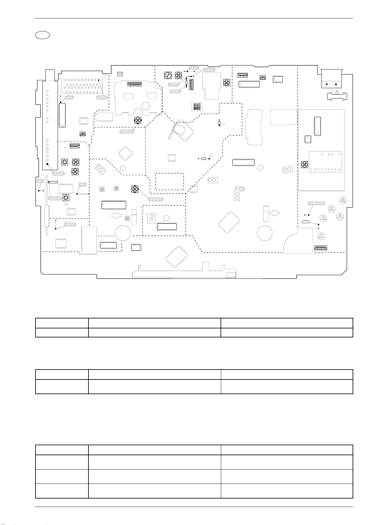
Chassisplatte (QMB).................................................................. 4-15
• Empfangseinheit (FV) ............................................................. 4-21
• OSD (OS)................................................................................ 4-24
• Follow-TV (FM) ....................................................................... 4-24
• VPS/PDC (VP) ........................................................................ 4-24
• Video/Chroma (VS)................................................................. 4-25
• Standardton (AL)..................................................................... 4-25
• IN/OUT (IO)............................................................................. 4-27
• SECAM-L (VS-S) .................................................................... 4-28
• FM-Ton (AF) ........................................................................... 4-29
• Kopfverstärker (HA) ................................................................ 4-30
• Netzteil (PS)............................................................................ 4-31
• Laufwerksteuerung / Deck-Elektronik (DE)............................. 4-33
• Bedieneinheit (DC).................................................................. 4-35
NICAM-Decoder (QNIC) ............................................................ 4-36
Oszillogramme ........................................................................... 4-38
Laufwerk .............................................5-1…5-12
Meßgeräte / Meßmittel................................................................. 5-1
Servicehinweise ........................................................................... 5-2
Auswechseln von Laufwerksteilen ............................................... 5-3
Einstellungen ............................................................................. 5-10
Layout of the PCBs
and Circuit Diagrams .........................4-1…4-40
Abbreviations ............................................................................... 4-1
Wiring Diagram ............................................................................ 4-3
Block Circuit Diagram .................................................................. 4-4
• Power Supply / Bus System...................................................... 4-4
• Video/Chroma ........................................................................... 4-7
• Standard Sound ...................................................................... 4-10
• FM Sound ............................................................................... 4-11
• Digital ...................................................................................... 4-13
Chassis Board (QMB) ................................................................ 4-15
• Frontend (FV).......................................................................... 4-21
• OSD (OS)................................................................................ 4-24
• Follow-TV (FM) ....................................................................... 4-24
• VPS/PDC (VP) ........................................................................ 4-24
• Video/Chroma (VS)................................................................. 4-25
• Standard Sound (AL) .............................................................. 4-25
• IN/OUT (IO)............................................................................. 4-27
• SECAM L (VS-S) .................................................................... 4-28
• FM Sound (AF) ....................................................................... 4-29
• Head Amplifier (HA) ................................................................ 4-30
• Power Supply (PS).................................................................. 4-31
• Drive Control / Deck Electronic (DE)....................................... 4-33
• Display Control (DC) ............................................................... 4-35
NICAM Decoder (QNIC) ............................................................ 4-36
Oscillograms .............................................................................. 4-38
Drive Mechanism................................5-1…5-12
Test Equipment / Jigs .................................................................. 5-1
Service Instructions...................................................................... 5-2
Replacement of Tape Deck Components .................................... 5-3
Adjustments ............................................................................... 5-10
Explosionszeichnungen
und Ersatzteillisten ............................6-1…6-20
1 - 2 GRUNDIG Service
Exploded Views and
Spare Parts Lists................................6-1…6-20
Page 3
GV 27 …, GV 47 …, GV 7… Allgemeiner Teil / General Section
Allgemeiner Teil / General Section
Geräteübersicht / Video Recorder Overview
GV 27 …, GV 47 …, GV 7… Allgemeiner Teil / General Section
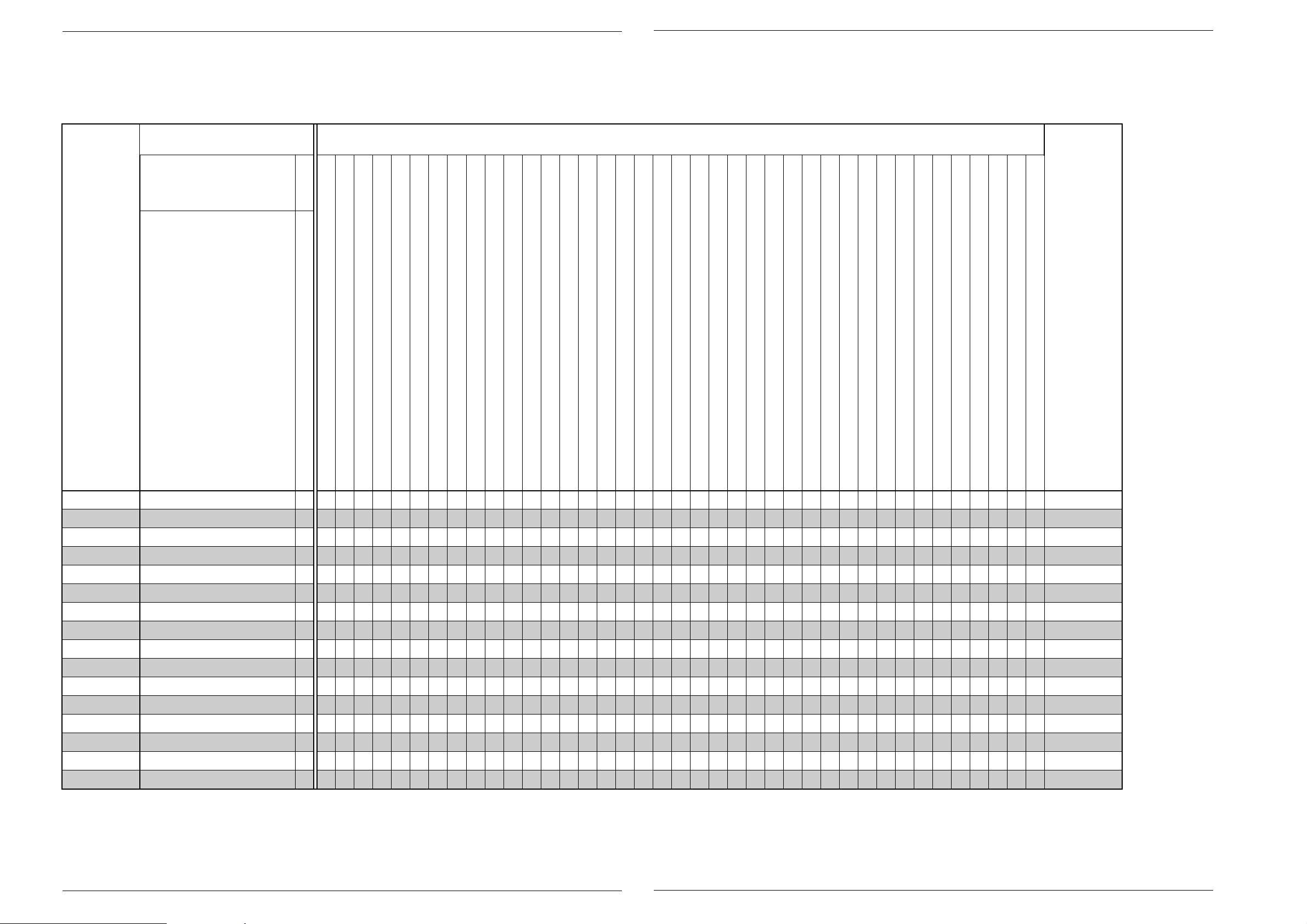
Bausteinübersicht
Table of Moduls
S./P 4-15
S./P 4-21
S./P 4-24
S./P 4-24
S./P 4-24
S./P 4-25
S./P 4-25
S./P 4-27
S./P 4-29
S./P 4-30
S./P 4-31
S./P 4-33
S./P 4-35
Feature-Übersicht
Table of Features
S./P 4-36NICAM-Decoder (QNIC)
GV 27
GV 27 VPS/5
GV 47
GV 47 VPS/5
GV 7000 SV
GV 7000 SV-C
GV 7003
GV 7300 SV
GV 7300 SV/5
GV 7400 HiFi
GV 7400 HiFi/5
GV 7400 NIC
KV 7001 VPS/5
KV 7301 VPS/5
SE 7100 SV
SE 7105 HiFi
Chassisplatte / Chassis Board (QMB)
· Empfangseinheit / Frontend (FV)
· OSD (OS)
· Follow TV (FM)
· VPS/PDC (VP)
· Video/Chroma (VS)
· Standardton / Standard Sound (AL)
· IN/OUT (IO)
· FM-Ton / FM Sound (AF)
· Kopfverstärker / Head Amplifier (HC)
· Netzteil / Power Supply (PS)
· Laufwerkssteuerung / Deck Electronic (DE)
· Bedieneinheit / Keyboard Control (DC)
• • • • • • • • • • • • • • • •
CCIR, B/G/H - PAL
• • • • • • • • • • • • • • • •
• • •
S-VHS-Aufnahme / S-VHS Record
NTSC-Wiedergabe / NTSC Playback
NICAM
CCIR, B/G/D/K - SECAM
• • • • • •
• • • • • • • • • •
• • •
Longplay
Normalplay
HiFi-Stereo
Rotierender Löschkopf / Flying Erase Head
2 Kopf / Head (Audio)
4 Kopf / Head (Video)
2 Kopf / Head (Video)
S-VHS-Wiedergabe / S-VHS Playback
• • • • • • •
• • • • • • • • •
• • • •
• • • • • • • • • • • • • • • •
• • • • • • • • •
• • • •
• • • • •
Teletext "DOS"
99 Programme
SHOW VIEW
6 Timer
PDC
VPS
Follow TV
Megalogic
Energiesparend / Low Power (Standby <6W)
• • • • • • • • • • • • • • • •
• • • • • • • • • • • • • • • •
• • • • • • • • • • • • • •
• • • • • • • • • • • •
• • • • • • •
• • • • • • • • • •
• • • • • • • • • •
VISS
Insert-Schnitt / Insert Edit
Nachvertonung / Dubbing
Kindersicherung / child lock
OSD
• • • • • • • • • • • • • • • •
• • • •
SAT-Steuerbuchse / SAT Remote Control
RS232-Buchse / Socket
Kopfhörerbuchse / Headphone Jack
Mikrofonbuchse / Micro Jack
"SYNCHRO-EDIT"-Buchse / Socket (ø 2,5mm Klinkenbuchse / mini-minijack)
S-VHS-Buchsen / S-VHS Sockets (IN/OUT)
CV-Eingangs-Buchsen / Input Sockets
LINE-Ausgangs-Buchsen / Output Sockets
LINE-Eingangs-Buchsen / Input Sockets
"PAY-TV"-Buchse / Socket (EURO-AV2)
EURO-AV-Buchse / Socket
Akustische Funktionskontorlle / Acoustic Function Control
• • • • • • • • • • • • • • • •
• • • • • • •
• • • •
GV 27
GV 27 VPS/5
GV 47
GV 47 VPS/5
GV 7000 SV
GV 7000 SV-C
GV 7003
GV 7300 SV
GV 7300 SV/5
GV 7400 HiFi
GV 7400 HiFi/5
GV 7400 NIC
KV 7001 VPS/5
KV 7301 VPS/5
SE 7100 SV
SE 7105 HiFi
GRUNDIG Service 1 - 3
GRUNDIG Service 1 - 4
Page 4

Allgemeiner Teil / General Section GV 27 …, GV 47 …, GV 7… Allgemeiner Teil / General Section GV 27 …, GV 47 …, GV 7…
Meßgeräte / Meßmittel
Regeltrenntrafo Farbgenerator
Zweikanaloszilloskop Tongenerator
Digitalmultimeter Stabilisiertes Netzgerät
Millivoltmeter Frequenzzähler
Beachten Sie bitte das Grundig Meßtechnik-Programm, das Sie unter
folgender Adresse erhalten:
Grundig Instruments
Test- und Meßsysteme GmbH
Würzburger Str. 150, D-90766 Fürth/Bay.
Tel. 0911/703-4118, Telefax 0911/703-4130
Sach-Nr.
Testcassette................................................................ 9.27540-1011
Testcassette (HiFi)...................................................... 9.27540-1016
Drehmomentmesser 600gf-cm ................................... 75987-262.72
Adapter für Drehmomentmesser 600gf-cm................. 75987-262.73
Einstellschraubendreher ............................................. 75987-262.80
Bandzug-Einstellgriff und -stift .................................... 75988-002.27
Kopfscheibenabzieher ................................................ 75988-002.37
Nylonhandschuhe ....................................................... handelsüblich
Tentelometer ............................................................... handelsüblich
Diese Meßmittel können Sie über die Serviceorganisation beziehen.
Wir weisen jedoch darauf hin, daß es sich hierbei z.T. um Meßmittel
handelt, die am Markt bereits eingeführt sind.
Testcassette Sach-Nr. 9.27540-1011
• Farbtestbild mit Dropout-Einblendung
• 6,3kHz-Senkrecht-Vollspuraufzeichnung und Bezugspegel 333Hz
in dreiminütigem Wechsel.
Testcassette (HiFi) Sach-Nr. 9.27540-1016
• Farbtestbild mit Dropout-Einblendung
• Längsspur-Ton: 6,3kHz und 333Hz
• FM-Ton: 1kHz Vollpegel (± 50kHz Hub)
Video-Lehrfilm Sach-Nr. 72007-744.81
• Laufwerk "High Speed Drive"
Test Equipment / Jigs
Variable isolating transformer Colour generator
Dual channel oscilloscope AF generator
Digital multimeter Stabilized power supply
Millivoltmeter Frequency counter
Please note the Grundig Catalog "Test and Measuring Equipment"
obtainable from:
Grundig Instruments
Test- und Meßsysteme GmbH
Würzburger Str. 150, D-90766 Fürth/Bay.
Tel. 0911/703-4118, Telefax 0911/703-4130
Part No.
Test cassette............................................................... 9.27540-1011
Test cassette (HiFi)..................................................... 9.27540-1016
Torquemeter 600gf-cm ............................................... 75987-262.72
Adapter for torquemeter 600gf-cm.............................. 75987-262.73
Adjustment screw driver.............................................. 75987-262.80
Tape tension adjustment tool - handle and pin ........... 75988-002.27
Headwheel extractor ................................................... 75988-002.37
Nylon gloves ...................................................... commonly available
Tentelometer ...................................................... commonly available
You can order these test equipments from the Service organization.
We refer to you that a number of these test equipments is already
obtainable on the market.
Test cassette Part No. 9.27540-1011
• Colour test pattern with dropout recording
• 6.3kHz vertical full-track recording alternating with 333Hz reference
level every 3 minutes.
Test cassette (HiFi) Part No. 9.27540-1016
• Colour test pattern with dropout recording
• Longitudinal track sound: 6.3kHz and 333Hz
• FM sound: 1kHz full level (± 50kHz deviation)
Video Training Film Part No. 72007-744.81
• Drive mechanism "High Speed Drive"
Anschlußmöglichkeiten:
EURO-AV1 / AV2
Audio
– Kontakt 1, Ausgang rechts ...........................500mV
– Kontakt 2, Eingang rechts .................................... 0,2…2V, ≥10kΩ
– Kontakt 3, Ausgang links..............................500mV
– Kontakt 6, Eingang links....................................... 0,2…2V, ≥10kΩ
±3dB, ≤1kΩ
eff
±3dB, ≤1kΩ
eff
Video
– Kontakt 19, Videoausgang (FBAS) ........... 1VSS +1dB / -2dB, 75Ω
– Kontakt 20, Videoeingang (FBAS) ....................... 1VSS ±3dB, 75Ω
Schaltspannung (bei nur einer EURO-AV-Buchse dient der Kontakt 8 als Aus- und Eingang)
– Kontakt 8,
Ausgang bei AV1
................ LOW 2V, HIGH 9,5V, Ansprechzeit 5ms, ≥10kΩ, ≤2nF
Eingang bei AV2............................. LOW 2V, HIGH ≥4,5V, ≥10kΩ
RGB (die Signale werden nur von der EURO-AV2 zur EURO-AV1-Buchse durchgeschleift)
– Kontakt 7, Blau
– Kontakt 11, Grün
– Kontakt 15, Rot
– Kontakt 16, Synchron
Audio-Ausgang (Geräterückseite)..................500mV
Hinweis:
±3dB, 1kΩ
eff
Diese Ausgänge sind den Ausgängen der EURO-AV1-Buchse parallel
geschaltet.
Modulator
Durchschleifbetrieb
– Frequenzgang .......................................................... 45…860MHz
– Dämpfung
Antenneneingang – TV-Ausgang .......................... 2dB +3dB/-2dB
Antenneneingang – Tuner-Ausgang ..................... 2dB +3dB/-2dB
Modulatorausgangskanal (über I
2
C-Bus einstellbar) .................. Kanal 21…55
Tuner
Frequenzgang.............................................................. 45…860MHz
Eingangspannung ....................................................... 60…100dBµV
Connections:
EURO-AV1 / AV2
Audio
– contact 1, right output................................. 500mV
– contact 2, right input ............................................. 0.2…2V, ≥10kΩ
– contact 3, left output................................... 500mV
– contact 6, left input ............................................... 0.2…2V, ≥10kΩ
±3dB, ≤1kΩ
rms
±3dB, ≤1kΩ
rms
Video
– contact 19, output video (CVBS)............... 1VPP +1dB / -2dB, 75Ω
– contact 20, input video (CVBS) ............................ 1VPP ±3dB, 75Ω
Switch voltage (if there is only one EURO-AV socket, contact 8 is used as input and output)
– contact 8,
AV1 output
....................... LOW 2V, HIGH 9.5V, rise time 5ms, ≥10kΩ, ≤2nF
AV2 input........................................ LOW 2V, HIGH ≥4.5V, ≥10kΩ
RGB (the signals are only looped through from the EURO-AV2 to EURO-AV1 socket)
– contact 7, blue
– contact 11, green
– contact 15, red
– contact 16, sync
Audio output (rear side) ................................ 500mV
Note:
±3dB, 1kΩ
rms
These outputs are connected in parrallel with the outputs of the EUROAV1 socket.
Modulator
Loop-through mode
– Frequency response ................................................ 45…860MHz
– Attenuation
Aerial input – TV output......................................... 2dB +3dB/-2dB
Aerial input – Tuner ouput ..................................... 2dB +3dB/-2dB
Modulator output channel (adjustable via I
2
C-bus) ............... Channel 21…55
Tuner
Frequency response .................................................... 45…860MHz
Input voltage ............................................................... 60…100dBµV
Technische Daten
VHS-System
1/2” Video - Cassettenrecorder
Bandgeschwindigkeit .............................. 2,339cm/s (Standard play)
Aufzeichnungsgeschwindigkeit ................... 4,84m/s (Standard play)
FS-Norm
CCIR, B/G/H - PAL
CCIR, B/G - SECAM
Video
Signal / Rauschabstand .........................................≥48dB (bewertet)
Auflösung ........................................................................... ca. 3MHz
Ton
Frequenzgang:
Standard play..................................................... 80Hz…10kHz ±4dB
Longplay .............................................................. 80Hz…5kHz ±4dB
FM-Ton ........................................................... 20Hz…20kHz ±1,5dB
Signal / Rauschabstand .........................................≥43dB (bewertet)
Gleichlaufschwankung: .......................................≤0,3% (DIN 45507)
Netzspannung ......................................................... 220V~…240V~
Netzfrequenz ................................................................... 45…63Hz
Leistungsaufnahme
– Aufnahme (Mono-Variante)............................................ ca. 12,5W
– Aufnahme (Stereo-Variante) ............................................. ca. 15W
– Stand by (Modulator aus)................................................. ca. 9,5W
– Energiesparbetrieb (Option).................................................... <6W
Umgebungstemperatur ...........................................+10°C…+35°C
Relative Luftfeuchte............................................................... ≤80%
Betriebslage ..................................................................... horizontal
Specifications
VHS-System
1/2” video cassette recorder
Tape speed ............................................. 2.339cm/s (Standard play)
Head to tape speed..................................... 4.84m/s (Standard play)
TV standard
CCIR, B/G/H - PAL
CCIR, B/G - SECAM
Video
Signal / noise ratio ................................................ ≥48dB (weighted)
Video resolution ................................................................. ca. 3MHz
Sound
Frequency response:
Standard play..................................................... 80Hz…10kHz ±4dB
Longplay .............................................................. 80Hz…5kHz ±4dB
FM Sound ....................................................... 20Hz…20kHz ±1.5dB
Signal / noise ratio ................................................ ≥43dB (weighted)
Wow and flutter ...................................................≤0.3% (DIN 45507)
Mains voltage .......................................................... 220V~…240V~
Mains frequency.............................................................. 45…63Hz
Power consumption
– Record (mono type) ....................................................... ca. 12.5W
– Record (stereo type) ......................................................... ca. 15W
– Stand by mode (Modulator off) ........................................ ca. 9.5W
– Low power (option) ................................................................. <6W
Ambient temperature ...............................................+10°C…+35°C
Relative humidity ................................................................... ≤80%
Operating position ...........................................................horizontal
1 - 5 GRUNDIG Service 1 - 6 GRUNDIG Service
Page 5
GV 27 …, GV 47 …, GV 7… Allgemeiner Teil / General Section
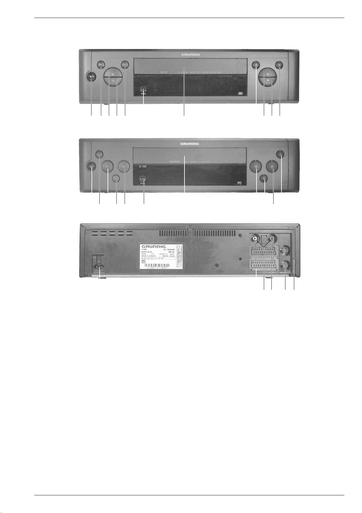
Operating Elements on the Video RecorderBedienelemente des Videorecorders
12345 6 7 890!
124 53 6 7 0 8 9!
@#$%^&
1 Schaltet den Videorecorder ab (Standby)
2 Zur Programmplatzwahl (bei Stop)
3 Cassettenauswurf
4 Aufnahme
5 Zur Programmplatzwahl (bei Stop)
6 Installation / ATS EURO Suchlauf
7 Cassettenfach
8 Bildsuchlauf rückwärts (bei Wiedergabe);
Rücklauf bei Stop
9 Startet die Wiedergabe
0 Pause;
Beendet alle Funktionen (Stop)
! Bildsuchlauf vorwärts (bei Wiedergabe);
Vorlauf bei Stop
@ Netzanschluß
# EURO-AV1-Buchse
$ Audioausgang
% EURO-AV2-Buchse
^ Antennenausgang
& Antenneneingang
1 Switches the recorder to standby
2 For selecting programme positions (on stop)
3 Cassette eject
4 Record
5 For selecting programme positions (on stop)
6 Installation / ATS EURO search
7 Cassette compartment
8 Reverse picture search (on playback);
rewind (on stop)
9 Starts playback
0 Pause;
Terminates all functions (stop)
! Forward picture search (on playback);
wind (on stop)
@ Mains socket
# EURO-AV1-socket
$ Audio output
% EURO-AV2-socket
^ Aerial socket output
& Aerial socket input
GRUNDIG Service 1 - 7
Page 6
Allgemeiner Teil / General Section GV 27 …, GV 47 …, GV 7…
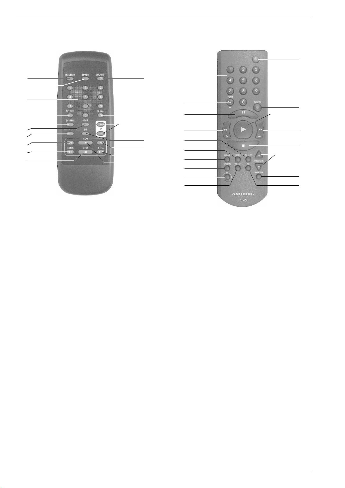
Bedienelemente der Fernbedienung
1
2
3
4
5
6
7
8
9
0
!
@
#
$
%
^
&
Operating Elements of the Remote Control
3
2
^
8
4
9
@
5
*
6
!
7
&
%
0
#
1
$
1 TV-Monitorfunktion
2 Eröffnet die Timer-Programmierung
und bestätigt Timer-Daten
3 Ziffern-Tasten für verschiedene Eingaben
4 Funktionswahl
5 Normumschaltung (ohne Funktion)
6 Schaltet auf Langspiel-Betrieb und wieder zurück auf
Standardspiel-Betrieb
7 Startet die Aufnahme
8 Bildsuchlauf rückwärts (bei Wiedergabe);
Rücklauf (bei Stop)
9 Wählt die INDEX-Such-Funktion
0 Pause;
Beendet alle Funktionen (Stop)
! Schaltet den Recorder ab (STANDBY);
aktiviert und deaktiviert die Kindersicherung (Option)
@ Löscht Daten
# Wählt den Programmplatz (bei Stop);
wählt Daten (bei der Timer-Programmierung)
$ Bestätigt Daten
% Bildsuchlauf vorwärts (bei Wiedergabe);
Vorlauf (bei Stop)
^ Standbild bei Wiedergabe
& Startet die Wiedergabe
* Fernsehgerät fernbedienen (dazu Taste TV gedrückt halten)
1
TV monitor function
2 Activates the timer programming function
and confirms timer data
3 Numbered buttons for various entries
4 Function selection
5 Standard switching (no function allocated)
6 Switches over to Long Play and back to
Standard Play
7 Starts recording function
8 Reverse picture search (on playback);
rewind (from stop)
9 Selects the INDEX search funktion
0 Pause;
Terminates all functions (stop)
! Switches the recorder off (Standby);
activates and deactivates the parental programme lock (Option)
@ Clears data
# Selects the programme position (from stop);
selects data (on timer programming)
$ Confirms data
% Forward picture search (on playback);
fast forward (from stop)
^ Freeze-frame on pla yback
& Starts playback function
* Remote control of television (press and hold down TV button)
1 - 8 GRUNDIG Service
Page 7
GV 27 …, GV 47 …, GV 7… Allgemeiner Teil / General Section
Servicehinweise
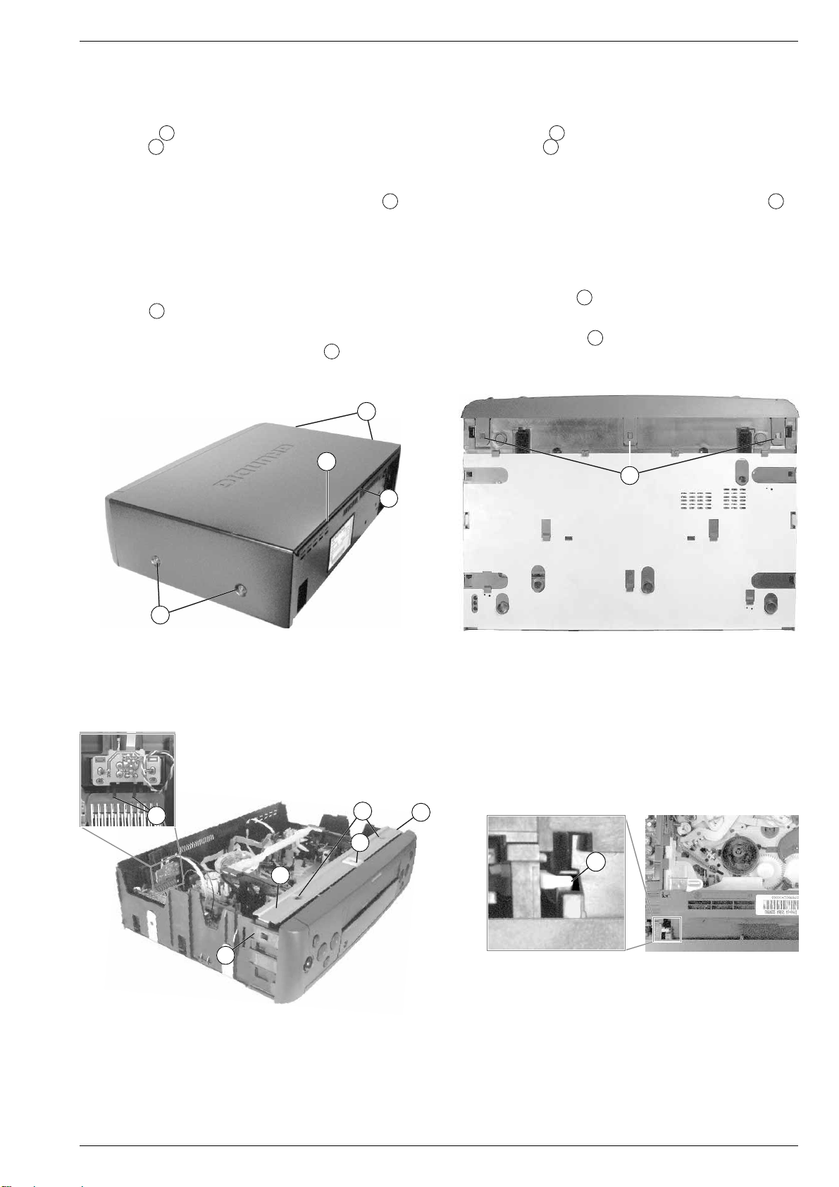
1. Entfernen der Gehäuseteile
1.1 Gehäuseoberteil
– 4 Schrauben A herausdrehen (Fig. 1).
– Rasthaken B (Fig. 1) lösen, Gehäuseoberteil hinten anheben und
1cm nach hinten schieben.
– Seitenteile des Gehäuseoberteils vorsichtig auseinanderziehen
und dabei Gehäuseoberteil abnehmen.
Montagehinweis: Das Gehäuseoberteil muß in die Rille C der
Rückwand eintauchen (Fig. 1).
1.2 Bodenblech
– Das Bodenblech darf aus Sicherheitsgründen (Massefedern durch-
trennen Leiterbahnen durch das Schieben des Bodenbleches) nicht
abgenommen werden.
1.3 Frontblende
– Rasthaken D (Fig. 2 / 3) lösen und Frontblende abnehmen.
Montagehinweis: Beim Aufstecken der Frontblende von vorne auf
das Gerät ist die Cassettenklappe so nach innen
zu drücken, daß der Hebel E in die Führung
(Fig. 4) der Cassettenklappe eintaucht.
A
C
B
Service Instructions
1. Removing the Cabinet Parts
1.1 Cabinet Upper Part
– Undo 4 screws A (Fig. 1).
– Release catch B (Fig. 1), lift the cabinet upper part on the rear edge
and push it backwards by 1cm.
– Remove the cabinet upper part by pressing its side panels carefully
apart.
Reassembly: The cabinet upper part must fit into the groove C on
the back panel (Fig. 1).
1.2 Bottom Panel
– For reasons of safety the bottom panel must not be removed (by
pushing the bottom panel the earthing springs cut the circuit tracks).
1.3 Front Panel
– Release the catches D (Fig. 2 / 3) and remove the front panel.
Reassembly: When attaching the front panel from the front to the
video recorder press the cassette lid inwards so that
the lever E engages with the guide (Fig. 4) of the
cassette lid.
D
S
siehe Punkt 1.2
see para 1.2
A
Fig. 1
H
F
D
D
Fig. 2
E
G
D
Fig. 3
Fig. 4
GRUNDIG Service 1 - 9
Page 8
Allgemeiner Teil / General Section GV 27 …, GV 47 …, GV 7…
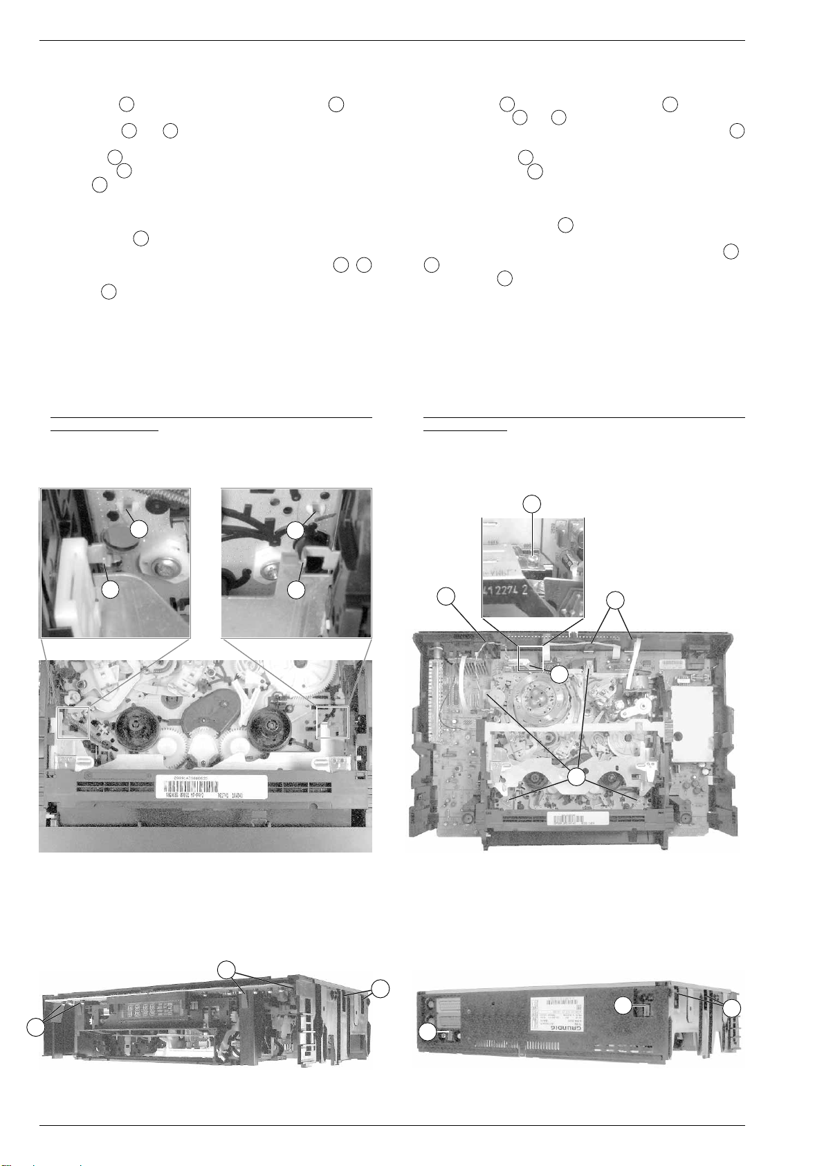
2. Ausbauhinweise
2.1 Chassisplatte mit Laufwerk ausbauen
– 2 Schrauben F (Fig. 3) herausdrehen und den Bügel G nach
oben abziehen.
– Arretierungen R und S (Fig. 5) des Cassettenschachtes lösen
und diesen dabei so weit nach innen schieben, bis die vorderen 2
Schrauben U (Fig. 6) zugänglich sind.
– 4 Schrauben U (Fig. 6) herausdrehen.
– 3 Kabel K (Fig. 6) aus den Haltern der Geräterückseite nehmen
und frei legen.
– Line-Buchsen-Platte (Option) ausbauen:
– Steckverbindungen zur Line-Buchsen-Platte lösen.
– 2 Rasthaken H (Fig. 3) lösen und die Line-Buchsen-Platte
herausziehen.
– Gerät auf die Oberseite legen (Fig. 7 / 8) und 10 Rasthaken I /
lösen (jede Seite von hinten nach vorne).
– Rastnase J (Fig. 8) nochmals lösen.
– Gehäuserahmen vorsichtig abnehmen.
Sicherheitshinweis:
– Nach dem Entfernen des Gehäuserahmens ist die Lötseite des
Netzteils frei zugänglich und damit auch alle lebensgefährlichen
Spannungen. Im Servicefall immer Trenntrafo benutzen!
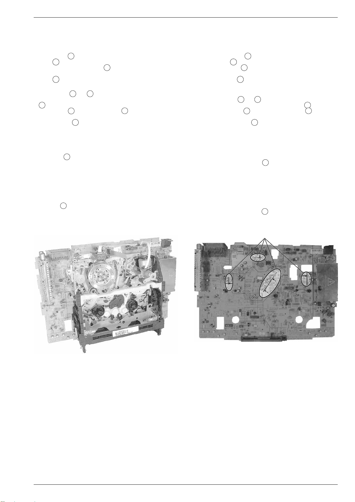
Servicestellung:
– Chassisplatte mit Laufwerk wie in Fig. 9 gezeigt aufstellen.
Achtung: Nicht die Cassetten-Ausgabe-Taste drücken und keinen
Abgleich durchführen.
2. Disassembly Instructions
2.1 Removing the Chassis Board with Mechanics
– Undo 2 screws F (Fig. 3) and raise the bracket G to remove it.
– Release the locks R and S (Fig. 5) of the cassette compartment
and move it inwards to gain access to the two front screws
(Fig. 6).
– Undo the 4 screws U (Fig. 6).
– Release the 3 cables K (Fig. 6) from their holders on the rear side
of the cabinet so that they are free.
– Remove the Line socket board (option):
– Unplug the connections to the Line socket board.
– Disengage the 2 catches H (Fig. 3) and pull out the Line socket
board.
J
– Put the VCR upside down (Fig. 7/8) and release the 10 catches I/
J
(from the back to the front on each side).
– Release catch J (Fig. 8) again.
– Remove the cabinet frame carefully.
Safety Precaution:
– After having removed the cabinet frame the solder side of the Power
Supply Board is freely accessible and with it all voltages dangerous
to life. Do not forget to use an isolating transformer during repairs!
Service Position:
– Place the Chassis Board with the Drive Mechanism in vertical
position as shown in Fig. 9.
Warning: Do not press the cassette eject button and do not carry out
any adjustments.
U
T
Y
R
Fig. 5 Fig. 6
Y
S
K
W
K
U
I
I
J
I
Fig. 7 Fig. 8
1 - 10 GRUNDIG Service
I
I
Page 9
GV 27 …, GV 47 …, GV 7… Allgemeiner Teil / General Section
Einbauhinweis:
– Chassisplatte mit Laufwerk (nur seitlich am Cassettenschacht
anfassen) so in den Gehäuserahmen legen, daß die Netzteilbuchse und die EURO-AV-Buchsen in den dafür vorgesehenen
Führungen sind. Alle 10 Rasthaken müssen dabei einrasten.
– 4 Schrauben U (Fig. 6) hineindrehen.
– Bügel G wie in Fig. 3 dargestellt auf den Gehäuserahmen stek-
ken und mit den 2 Schrauben F befestigen.
– Line-Buchsen-Platte (Option) einbauen und wieder anschließen.
– Kabel K (Fig. 6) in den Haltern der Geräterückseite einlegen.
2.2 Laufwerkausbau
– Arretierungen R und S (Fig. 5) des Cassettenschachtes lösen
und diesen dabei so weit nach innen schieben, bis die Schrauben
U
(Fig. 6) zugänglich sind.
– 4 Schrauben U und Masseschraube T (über die Bohrung der
Geräterückwand zugänglich) herausdrehen (Fig. 6).
– Abschirmblech W (Fig. 6) nach hinten biegen.
– 5 Steckverbindungen vom Laufwerk (Kopfscheibe, Löschkopf,
Kombikopf und Fädelmotor) zur Chassisplatte lösen.
– Laufwerk an der Geräterückseite vorsichtig etwas anheben, damit
sich die Steckverbindung 1946 zwischen dem Laufwerk und der
Chassisplatte löst.
– Rastnasen Y (Fig. 5) lösen und Laufwerk aus dem Gerät neh-
men.
Einbauhinweis:
– In die markierten Bereiche der Chassisplatte (Fig. 10) dürfen keine
Bauteile hineinragen. Die Bauteile (Kondensatoren) sind entspre-
chend der Pfeile auszurichten.
– Nach dem Einbau des Laufwerks ist die Masseverbindung zwi-
schen Chassisplatte und Laufwerk durch Eindrehen der Masse-
schraube T (Fig. 6) herzustellen.
Fitting Instructions:
– Put the Chassis Board together with the Drive Mechanism (take it
only by the side of the cassette compartment) into the cabinet frame
so that the mains socket and the EURO-AV sockets are in their
appropriate guides. All 10 catches must lock in.
– Tighten the 4 screws U (Fig. 6).
– Attach bracket G to the cabinet frame as shown in Fig. 3 and fasten
it with the 2 screws F.
– Re-fit the Line socket board (option) and re-connect it.
– Fasten the cables K (Fig. 6) with the holders on the rear side of the
cabinet.
2.2 Removing the Drive Mechanism
– Release the locks R and S (Fig. 5) of the cassette compartment
and move it inwards to gain access to the screws U (Fig. 6).
– Undo the 4 screws U and the earthing screw T (accessible
through the hole of the cabinet rear side) (Fig. 6).
– Push the shielding plate W (Fig. 6) to the rear.
– Disconnect the 5 plug-in connections from the Drive Mechanism
(headwheel, erase head, combi-head and threading motor) to the
Chassis Board.
– Lift the Drive Mechanism on the rear side carefully by a small amount
to disengage the plug-in connection 1946 between the Drive Mecha-
nism and the Chassis Board.
– Disengage the locking lugs Y (Fig. 5) and remove the Drive
Mechanism.
Fitting Instructions:
– Ensure that no components reach into the marked areas on the
Chassis Board (Fig. 10). Position the components (capacitors) as
shown by the arrows.
– After having re-fitted the Drive Mechanism, re-establish the chassis
connection between the Chassis Board and the Drive Mechanism by
tightening the earthing screw T (Fig. 6).
Fig. 9 Fig. 10
3. Wichtige Masseverbindungen!
Beim Zusammenbau des Gerätes ist darauf zu achten, daß die
Masseverbindungen zwischen Gehäuseboden und Chassisplatte,
Chassisplatte und Laufwerk sowie Gehäuseboden und Gehäuseoberteil gewährleistet sind.
siehe Punkt 2.2
see para 2.2
3. WARNING: Chassis Connections!
When reassembling the machine it is essential to observe that the
chassis connections between the cabinet bottom and Chassis Board,
Chassis Board and Drive Mechanism, cabinet bottom and cabinet
upper part are in good order.
4. Durchführen von Messungen
Bei Messungen mit dem Oszilloskop an Halbleitern sollten Sie nur
Tastköpfe mit 10:1 - Teiler verwenden. Außerdem ist zu beachten, daß
nach vorheriger Messung mit AC-Kopplung der Koppelkondensator
des Oszilloskops aufgeladen sein kann. Durch die Entladung über das
Meßobjekt können diese Bauteile beschädigt werden.
5. Meßwerte und Oszillogramme
Bei den in den Schaltplänen und Oszillogrammen angegebenen
Meßwerten handelt es sich um Näherungswerte!
GRUNDIG Service 1 - 11
4. Carrying out Measurements
When making measurements on semi-conductors with an oscilloscope, ensure that the test probe is set to 10:1 dividing factor. Further,
please note that if the previous measurement is made on AC input, the
coupling capacitor in the oscilloscope will be charged. Discharge via
the item being checked can damage components.
5. Measured Values and Oscillograms
The measured values given in the circuit diagrams and oscillograms
are approximates!
Page 10
Allgemeiner Teil / General Section GV 27 …, GV 47 …, GV 7…
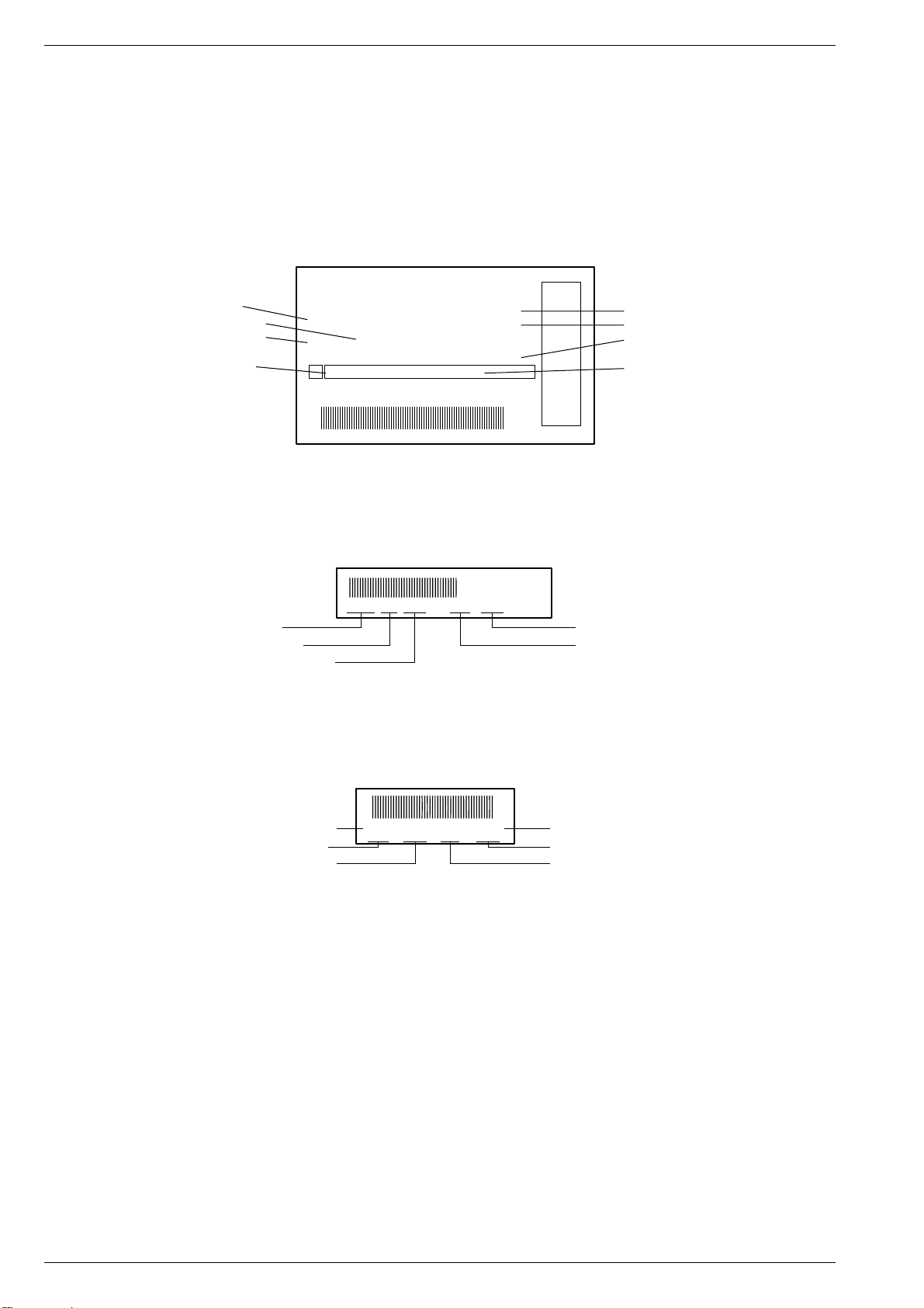
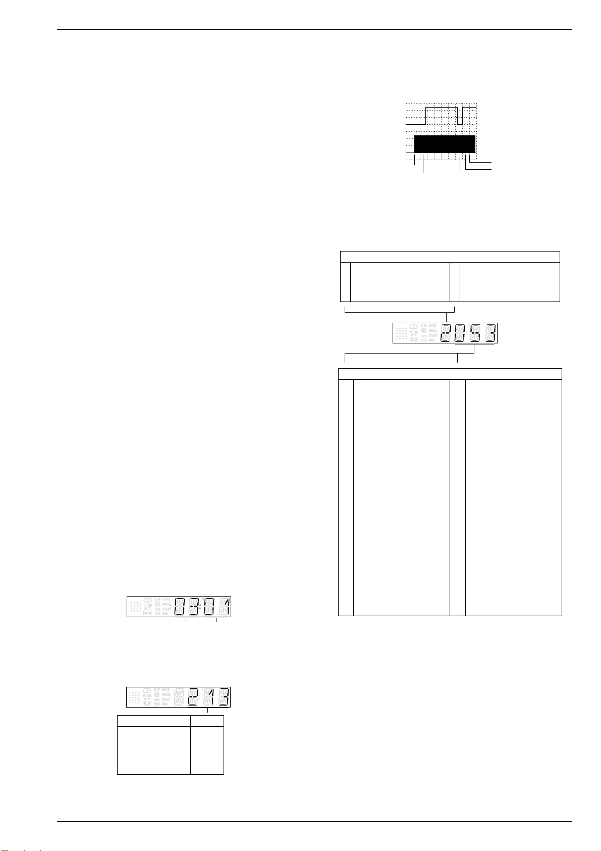
6. Codeaufkleber
Alle wichtigen Komponenten des Gerätes (Laufwerk / Platinen) sind
mit einem Codeaufkleber versehen. Diese Aufkleber beinhalten die
Typenbezeichnung und Produktionsdaten (Seriennummer, Produktionscode, Produktionsdatum, …).
Typenschild des Gerätes
Technische Weiterentwicklungen oder Änderungen sind wie folgt auf
dem Typenschild ersichtlich:
• Produktionscode – geringfügige Änderungen
• Entwicklungscode – gravierende Änderungen
1
Bestellnummer / Order number
Produktionsdatum / Production date
Produktionscode / Production code
Entwicklungscode / Evolution code
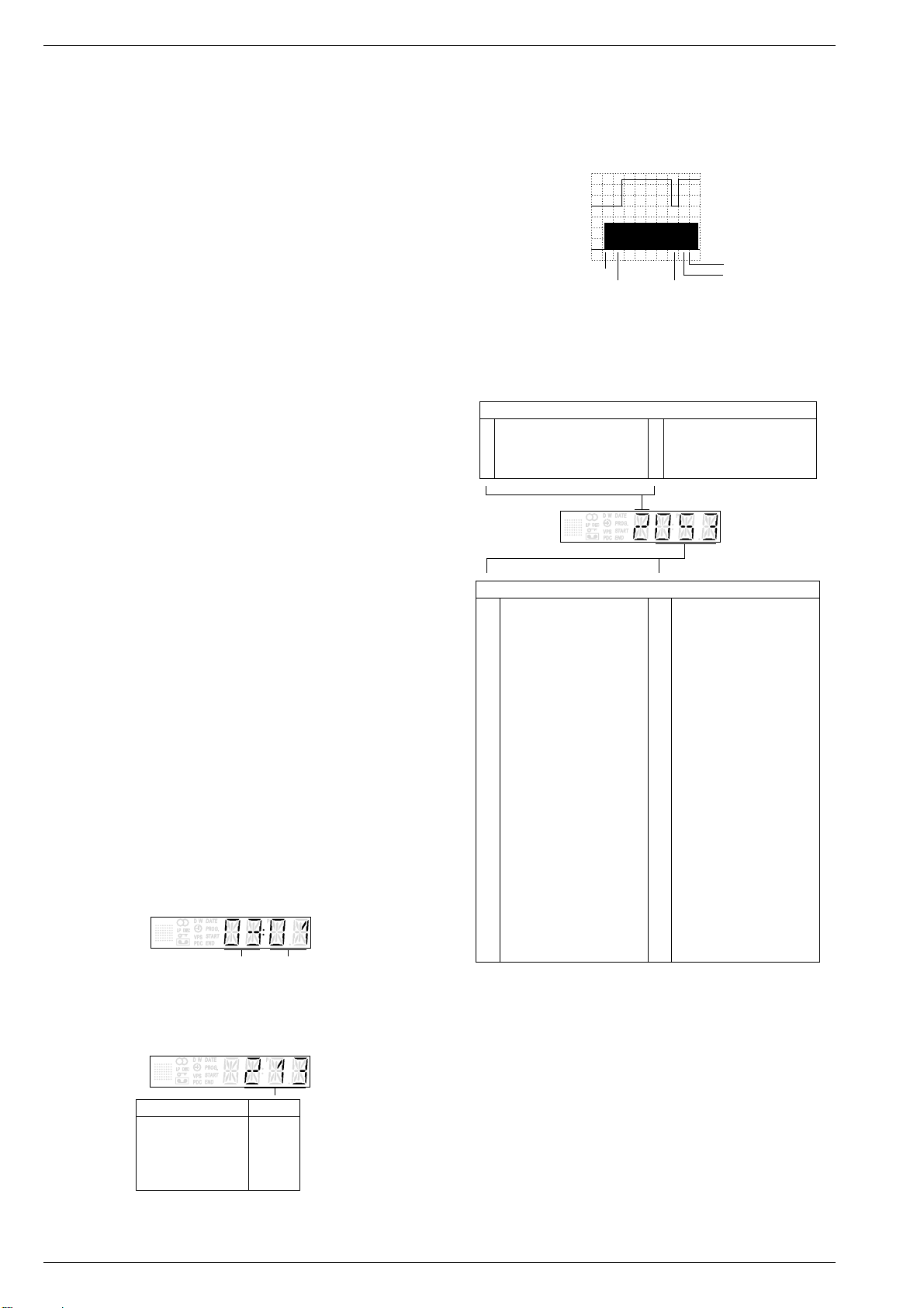
Laufwerks-Codeaufkleber
Hinweis:
Der Produktionscode und die Seriennummer auf dem Codeaufkleber
des Laufwerks müssen nicht mit dem Produktionscode und der Seriennummer auf dem Typenschild übereinstimmen.
TYPE
G.MG 25-00
VN 99 067
MADE IN EUROPE
S AA XXX XXX XXX XXX XXX
A
01 40393 5 52 0 100647 1
6. Code Labels
All important components of the video recorder (drive mechanism /
printed circuit boards) are provided with a code label. These adhesive
labels indicate the type of product and the production data (serial
number, production code, date of production, …).
Type Plate of the Set
Technical advance developments or changes are to be seen from the
type plate as follows:
• Production code – minor changes
• Evolution code – important changes
GV 7400 HIFI
RP 170
220-240V ~ 50Hz
SER.NR. 100647
UNDER LICENSE FROM
BY GEMSTAR DEVELOPMENT CORP.
GEMSTAR DEVELOPMENT CORPORATION
SHOW VIEW SYSTEMS IS MANUFACTURED
SHOW VIEW IS A TRADEMARK APPLIED FOR
Code Label on the Drive Mechanism
Advice:
The production code and the serial number on the code label of the
drive mechanism do not necessarily agree with the production code
and the serial number on the type plate.
Gerätetype / Type of product
Fernbedienung / Remote control
Seriennummer / Serial number
Geräte-Optionscode / Option code
10051442587303
25873030 10051 Q-P 4/2 971521 11WD44
Seriennummer / Serial number
Fabrikcode / Factory code number
Laufwerkstype / Type of drive mechanism
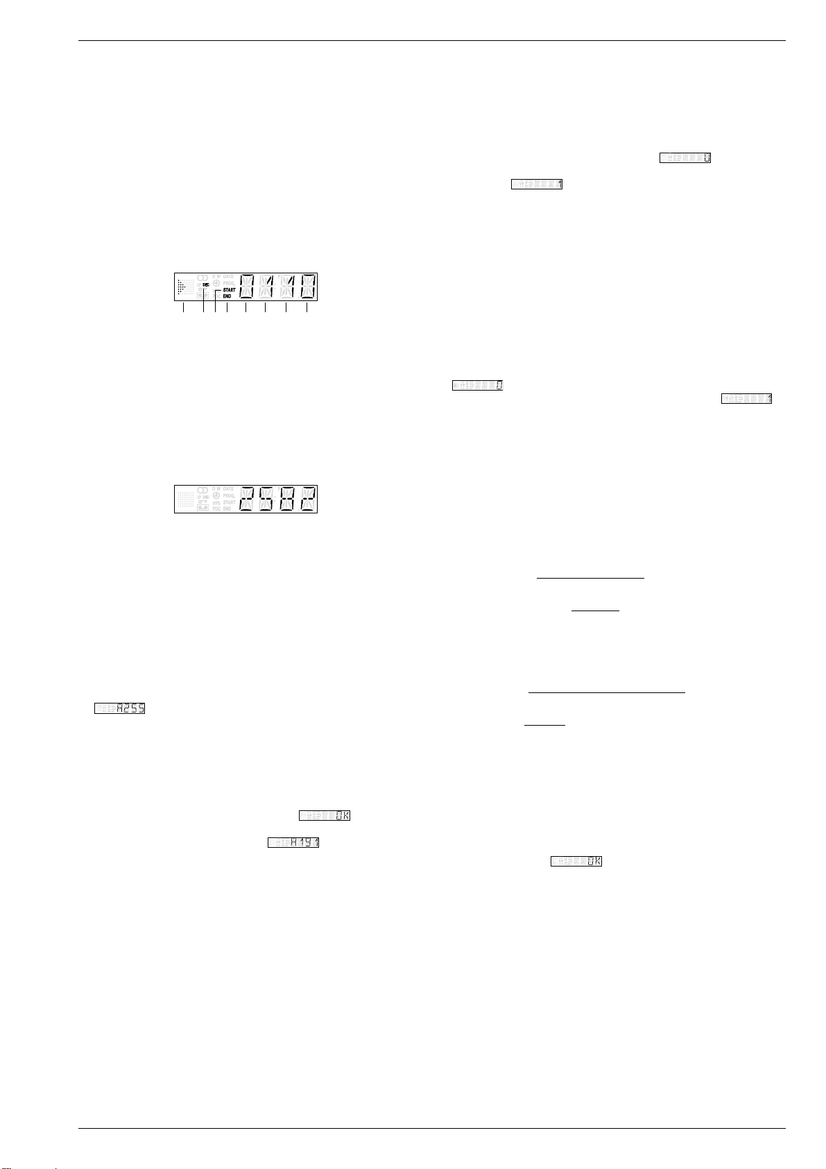
Platinen-Codeaufkleber
Hinweis:
Der Produktionscode ist nicht generell aufgedruckt. Bei wichtigen
Änderungen erhöht sich die letzte Ziffer der Fabrikscodenummer
(Punktnummer).
Platinenbezeichnung / Name of PCB
Fabrikcode / Factory code number
Produktionsdatum / Production date
QGD675021 27599-010.55
82162 KW724 WD01 123456
Produktionscode / Production code
Produktionsdatum / Production date
Code Label on the Printed Circuit Boards
Advice:
The production code is not generally printed on the label. Important
changes are indicated by increasing the last figure of the factory code
by one (figure following the point).
Sach-Nummer / Part number
Seriennummer / Serial number
Produktionscode / Production code
1 - 12 GRUNDIG Service
Page 11
GV 27 …, GV 47 …, GV 7… Servicetestprogramm & Sonderfunktionen
– Laufwerkstellung und Funktion des Init Schalters.
Servicetestprogramm & Sonderfunktionen
Das Diagramm zeigt die Funktion des Init-Schalters in Abhängigkeit
von der Stellung des Laufwerks. Dafür ist die Anzahl der Fädeltacho-
impulse (FTA) wichtig. Diese Impulse erzeugt der Fädeltachogeber
1. Servicetestprogramm
Aufruf, Ebenenkontrolle und Beenden des Servicetestprogrammes
Der Aufruf des Servicetestprogrammes ist bei allen Laufwerksfunktionen
(Flügelrad), der mechanisch mit dem Fädelmotor verbunden ist.
DC, 2V/Div, 0,5s/Div
Init Schalter
möglich, jedoch nicht während der Einstellfunktionen (Sendersuchlauf, …). Während des Servicemodes bleibt das Gerät bei allen
Laufwerksfunktionen voll einsatzbereit.
• Aufruf des Servicetestprogrammes
Die Tasten ■(STOP) auf der Fernbedienung und e(Wiedergabe)
am Gerät in dieser Reihenfolge drücken und für mindestens 5s
Cassette eingeschoben
Cassette unten Index, Umspulen
Fädeltacho-Impuls (FTA)
Wiedergabe rückwärts
Wiedergabe
gedrückt halten.
Im Display erscheinen anschließend die Werte der Ebene 00.
• Ebenenkontrolle des Servicetestprogrammes
Das Servicetestprogramm besteht aus folgenden Ebenen:
Ebene 00 – Masken-Nr. des Laufwerk- und Bedienrechners
Ebene 01 – Laufwerkstellung
Ebene 02 – Fehlercode und Fehlerstatus / Gerätefunktion
Ebene 03 – man. Tracking, Laufwerksensoren und Gerätefunktion
Ebene 04 – Betriebsstundenzähler
Ebene 10 – Laufwerksensoren und Gerätefunktion ohne Laufwerk-
ansteuerung
Ebene 40 – Geräte-Optionscodes
Ebene 02: Fehlercode und Fehlerstatus / Gerätefunktion
Der zuletzt aufgetretene Fehlerstatus und Fehlercode wird im EEPROM
gespeichert und bleibt auch dann erhalten, wenn das Gerät vom Netz
getrennt wird. Löschen kann man diese durch Drücken der Taste
"CLEAR" auf dem Fernbediengeber.
Fehlercode
0 Kein Fehler
1 Fädelfehler
2 Kein Capstantacho
3 Band gerissen
4 Kein Wickeltacho links (Option)
5 Kein Wickeltacho rechts
6 Kopfscheibenmotorfehler
Ebene 51 – Kopfscheibenlagengeber-Abgleich
Ebene 52 – ACC-Abgleich (Automatic Contour Control, optional)
Ebene 53 – Uhr-Takt-Abgleich
Ebene 60 – Audio-Pegeleinstellung des IC7780 (FV)
Ebene 61 – Audio-Kanaltrennung des IC7780 (FV)
Ebene 62 – Standardton-Wiedergabepegel des IC7850 (AF)
Ebene 99 – Uhr-Takt-Ausgabe
Ebenenanwahl
– Vor der Anwahl der Abgleich-Ebenen (51…62) ist auf die Vorbe-
reitung der jeweiligen Ebene zu achten (siehe die folgende
Beschreibung zu der jeweiligen Ebene des Servicetestprogrammes).
– Taste "SELECT" auf der Fernbedienung drücken. Im Display
blinkt die Ebenenanzeige.
– Mit der Taste "+" oder "–" auf die entsprechende Ebene weiter-
schalten oder mit den Tasten "0…9" die gewünschte Ebene direkt
anwählen.
– Mit der Taste "SELECT" die Eingabe bestätigen.
Bei der Anwahl einer nicht belegten Ebene blinkt im Display "--".
• Beenden des Servicetestprogrammes:
Taste 8 "STANDBY" drücken oder Gerät vom Netz trennen.
Ebenen des Servicetestprogrammes
Ebene 00: Masken-Nr. der Laufwerk- und Bedienrechner
Die Maskennummern der einzelnen Rechner werden wie folgt angezeigt.
Fehlerstatus / Gerätefunktion
012 Bereitschaft
014 Tracking
031 Bildsuchlauf rückwärts (3-fach)
034 Zeitlupe rückwärts
041 Standbild
042 Bildsuchlauf vorwärts (3-fach)
044 Bildsuchlauf rückwärts (9-fach)
045 Ausfädeln
046 Bildsuchlauf vorwärts (9-fach)
047 Wiedergabe rückwärts
048 Aufnahme – Pause
050 Rücklauf
052 Vorlauf
053 Wiedergabe
054 Stop
055 Aufnahme
112 Nächster Index
113 Vorheriger Index
114 VISS-Marke schreiben
115 VISS-Marke löschen
125 Tuner
126 Auto Remain
130 ATTS
168 Einzelbildfortschaltung +
169 Einzelbildfortschaltung –
170 Bildsuchlauf rückwärts (11-fach)
171 Bildsuchlauf rückwärts (7-fach)
172 Bildsuchlauf rückwärts (5-fach)
173 Bildsuchlauf vorwärts (5-fach)
174 Bildsuchlauf vorwärts (7-fach)
175 Bildsuchlauf vorwärts (11-fach)
196 EE-Betrieb
197 Bereitschaft - Schacht oben
199 Nachvertonung
202 Nachvertonung – Pause
206 Bandlängenzählwerk löschen
211 Zeitlupe (1/24)
212 Zeitlupe (1/14)
215 Zeitlupe (1/7)
216 Zeitlupe (1/2)
217 Zeitlupe rückwärts (1/24)
218 Zeitlupe rückwärts (1/14)
219 Zeitlupe rückwärts (1/7)
220 Zeitlupe rückwärts (1/2)
222 Sychro-Edit-Aufnahme
223
Kopfscheibenlagengeberabgleich
238 Pause
239 ACC-Abgleich
246 Synchro-Edit-Pause
247 Zeitlupe (1/10)
248 Zeitlupe (1/18)
249 Zeitlupe rückwärts (1/10)
250 Zeitlupe rückwärts (1/18)
253 Tastenfreigabe
Laufwerkrechner Bedienrechner
Ebene 01: Laufwerkstellung
Der Code für die Laufwerkstellung gibt die Positionen des Cassettenschachts und der Fädelschlitten an.
– Überwachung der Laufwerkfunktionen
Das Laufwerk wird mit Sensoren überwacht. Diese liefern entsprechend der Gerätefunktion folgende Tachosignale:
– WTR – Wickelteller rechts
– WTL – Wickelteller links (Option)
– FTA – Fädeltacho
– FG – Capstanmotor
– PG/FG – Kopfscheibenmotor.
Fehlt bei der Ansteuerung des Laufwerks ein Tachosignal, dann
Laufwerkstellung Code
Auswurf 005…009
Index 189…191
Ausgefädelt-Stop 196…204
Wiedergabe 209…217
Wiedergabe rückwärts 237…239
GRUNDIG Service 2 - 1
versucht das Gerät, den Cassettenschacht in die Stellung "EJECT"
zu bringen.
j
Page 12
Servicetestprogramm & Sonderfunktionen GV 27 …, GV 47 …, GV 7…
,
Ebene 03: man. Tracking, Laufwerksensoren und Gerätefunktion
– Manuelles Tracking
Die Trackinglage ist im Servicetestprogramm in der Mittelposition.
Durch das Betätigen der "+" oder "–" -Tasten ist die Verschiebung
der Trackinglage in die erforderliche Position für die Bandlaufeinstellung (s. Kap. 5 – Laufwerk) möglich.
– Laufwerksensoren
Zur Kontrolle der Laufwerksensoren (Init Schalter, Fädeltacho,
Bandanfang, Bandende, Aufnahmesperre, Wickeltacho Links /
Rechts) werden auf dem Display die Betriebszustände mit einer
Digitalstelle angezeigt. Mit jeder Betätigung der Sensoren ändern
sich die Werte der Anzeige.
– Gerätefunktion
Die Symbole ( ■ ● r e ) für die Gerätefunktion geben die Position
des Cassettenschachts und der Fädelschlitten an.
Gerätefunktion
Fädeltacho (FTA)
Init-Schalter (INIT)
Aufnahmesperre (RECP)
Bandende
Wickeltacho links (Option)
Bandanfang
Wickeltacho rechts
Ebene 04: Betriebsstundenzähler
Der Betriebsstundenzähler gibt die Betriebsstunden der Kopfscheibe
an.
Ebene 10: Laufwerksensoren und Gerätefunktion
ohne Laufwerkansteuerung
In dieser Ebene werden die Laufwerksensoren im Display angezeigt,
wie in der Ebene 03 erklärt. Des weiteren sind die Gerätefunktionen
anwählbar und für die Fehlersuche (ohne Laufwerk) werden die
entsprechenden Signalwege freigeschaltet.
In dieser Ebene erfolgt keine Ansteuerung des Laufwerks.
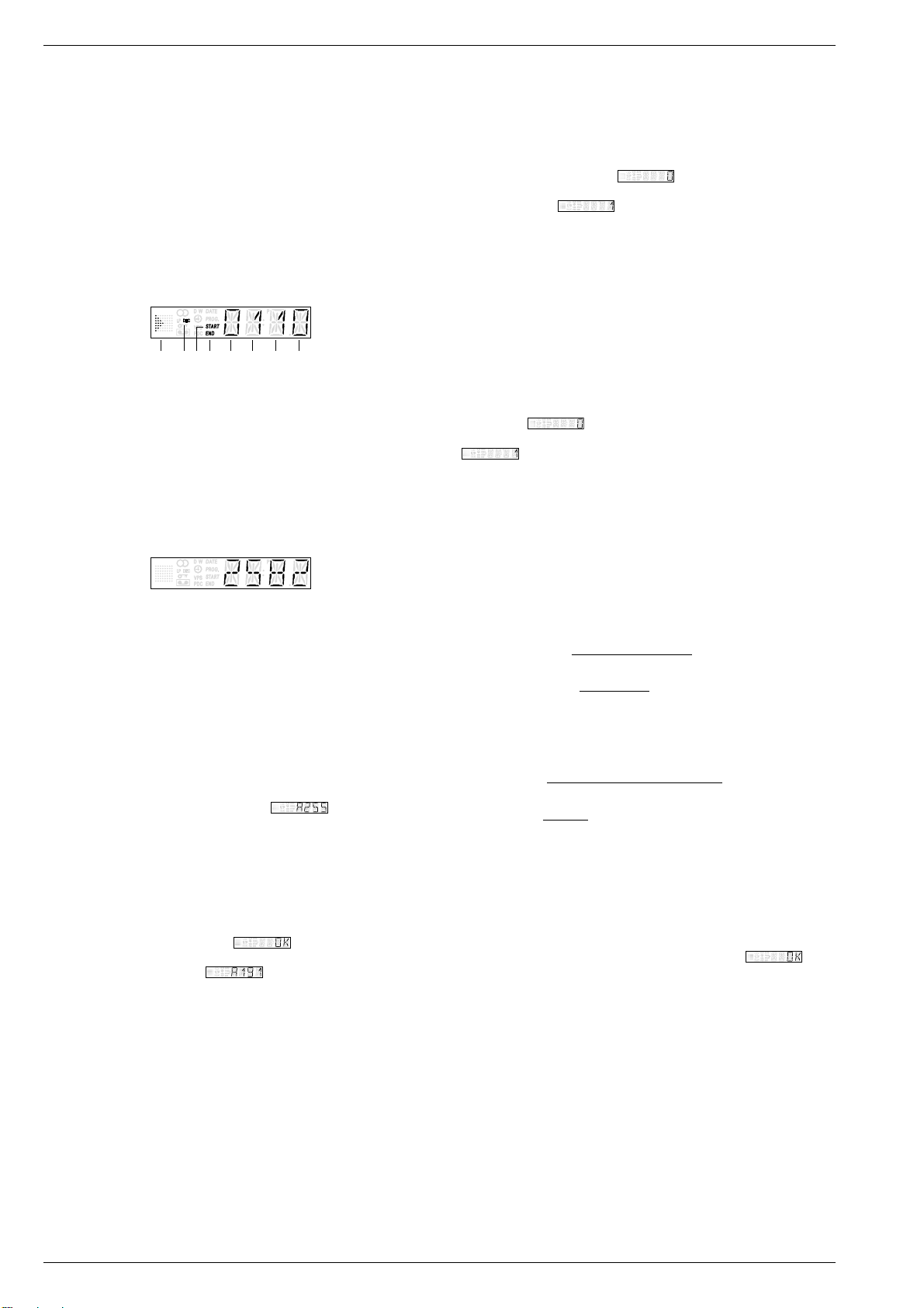
Ebene 40: Geräte-Optionscodes
Mit dem Geräte-Optionscode "A"…"E" wird gemäß dem Geräteaufbau
die entsprechende Software in den maskenprogrammierten µCs aktiviert. Der Optionscode wird im EEPROM gespeichert.
– Im Display erscheint nach dem Aufruf der Ebene 40 die Eingabe-
aufforderung für den Optionscode "A" ( ).
– Gewünschten Optionscode "A"…"E" mit den Tasten "–" oder "+"
anwählen.
– Eingabe der Optionscodes am Beispiel für Optionscode "A":
– Optionscode "A", siehe Geräte-Typenschild (z.B. "191") mit der
Fernbedienung eingeben.
Achtung: Nur bei richtiger Optionscode-Eingabe sind alle
Gerätefunktionen gewährleistet.
– Eingabecode mit der Taste "OK" bestätigen.
Im Display erscheint für ca. 3s . Anschließend schaltet
das Gerät automatisch zur Eingabeaufforderung zurück und zeigt
den gespeicherten Wert .
– Die Eingabeschritte der Optionscodes "B"…"E" sind genauso
durchzuführen wie bei dem Optionscode "A".
– Kontrolle der Optionscodes:
– Durch Betätigen der Tasten "–" oder "+" ohne vorheriger Options-
code-Eingabe ist die Kontrolle der die Optionscodes "A"…"E"
möglich.
Ebene 51: Kopfscheibenlagengeber-Abgleich
Der Kopfscheibenlagengeber-Abgleich ist nach dem Austausch der
Kopfscheibe oder des EEPROMs (IC7890) durchzuführen.
Vorbereitung vor dem Aufruf dieser Ebene:
– Testcassette wiedergeben.
Dieser Abgleich erfolgt nach dem Aufruf automatisch. Während dem
Abgleich zeigt das Display . Der Abgleichwert wird nach
erfolgreich durchgeführtem Abgleich im EEPROM gespeichert. Im
Display erscheint .
Bei nicht erfolgreich durchgeführtem Abgleich gibt das Gerät die
Cassette aus und verläßt das Servicetestprogramm. Ursache: Testcassette, Kopfscheibe oder technischer Defekt (z.B. µC)
Ebene 52: ACC-Abgleich (Automatic Contour Control, optional)
Der ACC-Abgleich ist nach dem Austausch der Kopfscheibe oder des
EEPROMs (IC7890) durchzuführen.
Vorbereitung vor dem Aufruf dieser Ebene:
– Schwarztestbild ohne Burst an der EURO-AV1-Buchse einspeisen
– Aufnahme- / Wiedergabe-Cassette wiedergeben.
Dieser Abgleich erfolgt nach dem Aufruf automatisch
(15s eine Aufnahme in den Betriebsarten SP/LP und bei der Wiedergabe dieser
Aufnahme wird das Gerät abgeglichen)
. Während dem Abgleich zeigt
das Display . Der Abgleichwert wird nach erfolgreich durchgeführtem Abgleich im EEPROM gespeichert. Im Display erscheint
.
Bei nicht erfolgreich durchgeführtem Abgleich gibt das Gerät die
Cassette aus. Ursache: Vorbereitung, Cassette, Kopfscheibe oder
technischer Defekt (z.B. µC)
Ebene 53: Uhr-Takt-Abgleich
Vorbereitung vor dem Aufruf dieser Ebene:
– Ebene 99 – Uhr-Takt-Ausgabe durchführen und Meßwert (f
notieren.
mess
– Ermittlung des Korrekturwertes:
f
= gemessene Frequenz
mess
f
= Sollfrequenz (2048,0000Hz)
soll
Abweichung =
Korrekturwert = +128
1 x 10⁶ x (f
Abweichung
0,763
f
mess
soll
– f
soll
)
Beispiel:
f
= 2047,9700Hz
mess
f
= 2048,0000Hz
soll
-14,648 =
108,80 = +128
1 x 106 x (2047,97Hz – 2048Hz)
2048Hz
-14,648
0
763
Korrekturwert gerundet für Eingabe: 109
Liegt der errechnete Korrekturwert außerhalb des Bereiches 0…255
ist ein technischer Defekt des Quarzes Q1297 möglich.
Eingabe des Korrekturwertes
– Im Display erscheint nach dem Aufruf der Ebene 53 der im Gerät
aktuelle Korrekturwert "0"…"255".
– Korrekturwert (gerundet) eingeben und mit der Taste "OK" bestäti-
gen. Im Display erscheint zur Kontrolle für ca. 3s .
)
2 - 2 GRUNDIG Service
j
Page 13

GV 27 …, GV 47 …, GV 7… Servicetestprogramm & Sonderfunktionen
Ebene 60: Audio-Pegeleinstellung des IC7780 (FV, Option)
Die Audio-Pegeleinstellung ist nach dem Austausch des Stereodecoders (IC7780) oder des EEPROMs (IC7890) durchzuführen.
Vorbereitung vor dem Aufruf dieser Ebene:
– NF-Millivoltmeter an der EURO-AV1-Buchse, Kontakt 1 anschlie-
ßen
– Weißtestbild mit Tonträger (Tonmodulation "Stereo", rechter Kanal
1kHz Sinus, ±27kHz Hub) an der Antenneneingangsbuchse einspeisen
– EE-Betrieb.
Nach dem Aufruf der Ebene 60 erscheint der aktuelle Einstellwert
"0"…"9". Der Ausgangspegel ist mit den Tasten "–" oder "+" auf
500mV
Pegeländerung von 0,5dB und der Einstellwert wird im EEPROM
abgelegt.
Ebene 61: Audio-Kanaltrennung des IC7780 (FV, Option)
Die Audio-Kanaltrennung ist nach dem Austausch des Stereodecoders
(IC7780) oder des EEPROMs (IC7890) durchzuführen.
Vorbereitung vor dem Aufruf dieser Ebene:
– NF-Millivoltmeter an der EURO-AV1-Buchse, Kontakt 3 (linker
– Weißtestbild mit Tonträger (Tonmodulation "Stereo", rechter Kanal
– EE-Betrieb.
Nach dem Aufruf der Ebene 61 erscheint der aktuelle Einstellwert
"0"…"49". Die Rauschspannung des linken Kanals ist mit den Tasten
"–" oder "+" auf Minimum einzustellen. Dabei erfolgt pro Tastendruck
eine Pegeländerung von 0,1dB und der Einstellwert wird im EEPROM
abgelegt.
Ebene 62: Standardton-Wiedergabepegel des IC7850 (AF, Option)
Der Standardton-Wiedergabepegel ist nach dem Austausch des IC7850
oder des EEPROMs (IC7890) durchzuführen.
Vorbereitung vor dem Aufruf dieser Ebene:
– NF-Millivoltmeter an der EURO-AV1-Buchse, Kontakt 1 anschließen
– Tonsignal (1kHz Sinus, 0,7V
– FBAS-Signal an der EURO-AV1-Buchse einspeisen
– Tonsignal aufnehmen.
Nach dem Aufruf der Ebene 62 erscheint der aktuelle Einstellwert
"0"…"15". Das aufgenommene Tonsignal ist wiederzugeben (Standardton-Wiedergabe) und der Ausgangspegel mit den Tasten "–" oder "+"
auf 500mV
Pegeländerung von 1dB und der Einstellwert wird im EEPROM abgelegt.
Ebene 99: Uhr-Takt-Ausgabe
Für den Uhr-Takt-Abgleich (Ebene 53) ist in dieser Ebene die UhrOszillatorfrequenz (ca. 2048Hz) an IC7201-(80) "HEST" der
Bedieneinheit (DC) zu messen (Auflösung mindestens 6 Stellen) und
notieren (f
Hinweis:
Nach der Anwahl dieser Ebene ist das Display dunkel und keine
Funktion am Gerät möglich. Das Verlassen dieser Ebene und des
Servicetestprogrammes ist nur durch das Trennen des Gerätes vom
Netz möglich.
±50mV einzustellen. Dabei erfolgt pro Tastendruck eine
eff
Kanal) anschließen
1kHz Sinus, ±27kHz Hub) an der Antenneneingangsbuchse ein-
speisen
) an der EURO-AV1-Buchse, Kontak-
te 2 und 6 einspeisen
±50mV einzustellen. Dabei erfolgt pro Tastendruck eine
eff
).
mess
eff
2. Sonderfunktionen
Dauerlaufprüfung
Die Aufnahme- oder Wiedergabe-Dauerlaufprüfung ist im Servicetestprogramm integriert. Diese hilft Fehler zu finden, die sporadisch
auftreten. Ein erkannter Fehler wird im EEPROM gespeichert und
bleibt erhalten, wenn das Gerät vom Netz getrennt wird.
Aufruf der Dauerlaufprüfung
– Dauerlaufprüfung starten mit einer der Tasten ●(Aufnahme)
oder e(Wiedergabe).
Beenden der Dauerlaufprüfung
– Taste ■(STOP) oder 8 "STANDBY" drücken.
Reinigung der Kopfscheibe
Beim Einfädeln des Videobandes werden die Videoköpfe nur kurzzeitig gereinigt. Im Wiedergabebetrieb kann diese Funktion durch Drükken der Taste e(mindestens 5s) für ca. 10s aktiviert werden. Dabei
wird der Bandvorschub gestoppt und die Videokopfreinigungsrolle an
die Kopfscheibe gedrückt. Anschließend wird die Wiedergabe wieder
fortgesetzt.
RAM und EEPROM löschen
Am Gerät die Taste 8 "STANDBY" drücken und nach dem Anschließen des Gerätes an das Netz für mindestens 5s gedrückt halten.
Das EEPROM und das interne Prozessor-RAM werden gelöscht und
initialisiert. Dabei werden der kundenspezifische Senderspeicher und
die Timer-Daten gelöscht. Die gerätespezifischen Daten, Laufwerkparameter, Geräte-Optionscodes und die Abgleichwerte bleiben erhalten.
Tausch des EEPROMs IC7890
Achtung: Nach dem Tausch des EEPROMs, IC7890, müssen die
Geräte-Optionscodes der Ebene 40 eingegeben werden.
Des weiteren sind die Software-Abgleiche der Ebenen 51,
52, 53, 60, 61 und 62 durchzuführen.
Data-Programmer "IDP2"
Hinweis: Die Übertragung der im Data-Programmer gespeicherten
Sendereinstellungen ist nur über den VCR1-Mode möglich.
– Taste "EJECT" drücken (eingelegte Cassette ausgeben).
– Die Tasten ■(STOP) auf der Fernbedienung und "INSTALL" am
Gerät in dieser Reihenfolge drücken und für mindestens 5s gedrückt
halten. Im Display erscheint anschließend "MENU".
– Sendereinstellungen mit dem Data-Programmer "IDP2" übertragen
(siehe Bedienungsanleitung "IDP2").
– Am Ende der Übertragung Taste 8 "STANDBY" drücken.
GRUNDIG Service 2 - 3
j
Page 14
Service Test Programme & Special Functions GV 27 …, GV 47 …, GV 7…
– Tape deck position and function of the Init switch
Service Test Programme & Special Functions
The diagram shows the function of the Init switch dependent on the
tape deck position. For this, the number of the threading tacho
pulses (FTA) is important. These signals are generated by the
1. Service Test Programme
threading tacho generator (butterfly sensor) which is mechanically
connected with the threading motor.
Calling up, Checking the Levels of and Terminating the Service Test
Programme
The service test programme can be called from any tape drive function
DC, 2V/Div, 0.5s/Div
Init switch
other than the data entry functions (station search, …). While it is
operating in the service mode, the VCR remains fully operational in all
tape drive functions.
• Calling up the Service Test Programme
Press the ■(STOP) button on the remote control and the e(Play)
button on the video recorder in that order and hold them down for at
Cassette in
Cassette down
Threading pulse (FTA)
Play reverse
Index, wind-rewind
Play
least 5 seconds.
The display will then show the values of Level 00.
• Checking the Levels of the Service Test Programme
The service test programme is made up of the following levels:
Level 00 – mask no. of the tape deck and keyboard control computer
Level 01 – tape deck position
Level 02 – error code and error status / VCR function
Level 03 – man. tracking, tape deck sensors and VCR function
Level 04 – operating hours meter
Level 10 – tape deck sensors and VCR function without drive to the
tape deck
Level 40 – VCR option codes
Level 02: Error Code and Error Status / VCR Function
The last error status and error code that occurred is stored in the
EEPROM and is saved even if the VCR is disconnected from the
mains. The data can be cleared by pressing the "CLEAR" button on the
remote control.
Drive Mechnism Error Code
0 No Error
1 Threading error
2 No capstan tacho
3 Tape torn
4 Missing left reel tacho (option)
5 Missing right reel tacho
6 Headwheel motor error
Level 51 – headwheel position indicator adjustment
Level 52 – ACC adjustment (Automatic Contour Control, option)
Level 53 – timer clock adjustment
Level 60 – audio level adjustment of IC7780 (FV)
Level 61 – audio channel separation of IC7780 (FV)
Level 62 – standard sound playback level of IC7850 (AF)
Level 99 – timer clock output
Level Selection
– Before selecting the adjustment levels (51…62) remember to
prepare the respective level first (see description of the individual
levels of the service test programme given below).
– Press the "SELECT" button on the remote control. The indication
of the level flashes on the display.
– With the "+" or "–" button switch over to the respective level or
select the desired level directly with the buttons "0…9".
– Confirm the entered figures with the "SELECT" button.
On selection of an unused level the indication "--" flashes on the
display.
• Terminating the Service Test Programme:
Press the 8 "STANDBY" button or disconnect the VCR from the
mains.
Levels of the Service Test Programme
Level 00: Mask No. of Tape Deck and Keyboard Control Computers
The mask number of the individual computers is indicated as follows:
Tape Deck Computer Keyboard Control Computer
Level 01: Tape Deck Position
The tape deck position code indicates the position of the cassette
compartment and of the threading roller units.
Drive Mechnism Error Status / VCR Function
012 Standby
014 Tracking
031 Picture search reverse (3x)
034 Slow reverse
041 Still
042 Picture search forward (3x)
044 Picture search reverse (9x)
045 Threaded out
046 Picture search forward (9x)
047 Play reverse
048 Record – Pause
050 Rewind
052 Wind
053 Play
054 Stop
055 Record
112 Next index
113 Previous index
114 Write VISS marks
115 Clearing VISS marks
125 Tuner
126 Auto Remain
130 ATTS
168 Frame forward
169 Frame reverse
170 Picture search reverse (11x)
171 Picture search reverse (7x)
172 Picture search reverse (5x)
173 Picture search forward (5x)
174 Picture search forward (7x)
175 Picture search forward (11x)
196 EE mode
197 Standby Eject
199 Audio Dubbing
202 Audio Dubbing Pause
206 Reset Tapecounter
211 Slow (1/24)
212 Slow (1/14)
215 Slow (1/7)
216 Slow (1/2)
217 Slow reverse (1/24)
218 Slow reverse (1/14)
219 Slow reverse (1/7)
220 Slow reverse (1/2)
222 Sychro-Edit-Record
223 Auto Gap Position Adjustment
238 Pause
239 ACC Adjustment
246 Synchro-Edit-Pause
247 Slow (1/10)
248 Slow (1/18)
249 Slow reverse (1/10)
250 Slow reverse (1/18)
253 Keyboard Enable
– Monitoring the tape deck functions
For monitoring the tape deck functions the tape deck is fitted with
sensors which supply the following tacho signals according to the
functions:
– WTR – reel right
– WTL – reel left (option)
– FTA – threading tacho
– FG – capstan motor
Tape Deck Positions Code
Eject 005…009
Index 189…191
Stop threaded out 196…204
Play position 209…217
Play reverse 237…239
– PG/FG – headwheel motor
When one tacho pulse is missing during the operation of the tape
deck, the VCR tries to move the cassette compartment to the
"EJECT" position.
2 - 4 GRUNDIG Service
k
Page 15
GV 27 …, GV 47 …, GV 7… Service Test Programme & Special Functions
Level 03: Man. Tracking, Tape Deck Sensors and VCR Function
– Manual tracking
The tracking position in the service test programme is set to midposition. By pressing the "+" or "–" button it is possible to change the
tracking position to the required position for tape transport adjustment (see chap. 5 – Tape Deck).
– Tape deck sensors
For checking the tape deck sensors (Init switch, threading tacho,
tape start, tape end, record lock, winding tacho left / right) the
operating positions are indicated on the display by means of one
digit. The indicated value changes with each operation of the
sensors.
– VCR function
The VCR function symbols ( ■ ● r e ) indicate the position of the
cassette compartment and of the threading roller units.
VCR function
Init switch (INIT)
Threading tacho (FTA)
End of Tape
Beginning of tape
Record prodection (RECP)
Right reel tacho
Left reel tacho (Option)
Level 04: Operating Hours Meter
The operating hours meter indicates the number of hours the headwheel has been rotating.
Level 10: Tape Deck Sensors and VCR Function
without Drive to the Tape Deck
At this level, the tape deck sensors are indicated on the display as
explained at Level 03. Additionally, the VCR functions can be selected
and the respective signal paths are released for fault finding (without
tape deck).
The tape deck is not driven at this level.
Level 40: VCR Option Codes
The VCR option codes "A"…"E" serve the purpose of activating the
respective software of the different VCR versions stored in the maskprogrammed µC's. The option code is stored in the EEPROM.
– When calling up Level 40 the request for entering option code "A"
( ) appears on the display.
– Select the desired option code "A"…"E" with the "–" or "+" button.
– Entering the option code, for example option code "A":
– Enter option code "A", see VCR type plate (e.g. "191"), on the
remote control.
Attention: All functions will be available only if the option code
has been entered correctly.
– Confirm the entered code with the "OK" button.
The display shows for approximately 3s . Afterwards,
the recorder switches back automatically requesting another
entry and shows the stored value .
– The option codes "B"…"E" are entered in the same way as option
code "A".
– Checking the option codes:
– The option codes "A"…"E" can be checked by pressing the "–" or
"+" button without having entered an option code previously.
Level 51: Headwheel Position Indicator Adjustment
This adjustment is necessary on replacement of the headwheel or
EEPROM (IC7890).
Preparation before calling up this level:
– Play the test cassette.
This adjustment is started automatically on calling up the level. During
the adjustment process the display shows . On successful
completion the resulting value is stored in the EEPROM. The display
then shows .
If the adjustment is not carried out successfully the machine ejects the
cassette and terminates the service test programme. Cause: Test
cassette, headwheel or technical defect (e.g. µC)
Level 52: ACC Adjustment (Automatic Contour Control, option)
The ACC needs to be adjusted on replacement of the headwheel or
EEPROM (IC7890)
Preparation before calling up this level:
– Feed in a black raster test pattern without burst to EURO-AV1 socket
– Play back the record / play cassette.
This adjustment is started automatically on calling up this level
(recording for 10s in SP/LP mode each and while playing back this recording
the VCR is adjusted)
. During this process the display shows
.The resulting value is stored in the EEPROM on successful
completion of this adjustment. The display then shows .
If the adjustment is not carried out successfully the machine ejects the
cassette. Cause: Preparation, cassette, headwheel or technical defect (e.g.
µC).
Level 53: Timer Clock Adjustment
Preparation before calling up this level:
– Level 99 - measure the timer clock output and note down the
measured value (f
– Calculation of the correction value:
f
= measured frequency
mess
f
= desired frequency (2048.0000Hz)
soll
Deviation =
Correction value = +128
).
mess
1 x 10⁶ x (f
Deviation
mess
f
soll
0.763
– f
soll
)
Example:
f
= 2047.9700Hz
mess
f
= 2048.0000Hz
soll
-14.648 =
108.80 = +128
1 x 106 x (2047.97Hz – 2048Hz)
2048Hz
-14.648
0.763
Rounded correction value to be entered: 109
If the calculated correction value lies outside the range 0…255 the
quartz Q1297 may be technically defective.
Entering the correction value
– On calling up Level 53 the display shows the currently valid correc-
tion value "0"…"255".
– Enter the correction value (rounded) and confirm the value by
pressing the "OK" button. As a check, the display shows for
approximately 3s .
GRUNDIG Service 2 - 5
k
Page 16

Service Test Programme & Special Functions GV 27 …, GV 47 …, GV 7…
Level 60: Audio Level Adjustment of IC7780 (FV, option)
The audio level is to be adjusted on replacement of the stereo decoder
(IC7780) or the EEPROM (IC7890).
Preparation before calling up this level:
– Connect the AF millivoltmeter to the EURO-AV1 socket, contact 1
– Feed in a white test pattern with sound carrier ("stereo" sound
modulation, right channel 1kHz sine, ±27kHz deviation) to the aerial
input socket
– EE operating mode
On calling up adjustment level 60, the actual setting "0"…"9" is
displayed. Set the output level with the button "–" or "+" to 500mV
±50mV. Each time one of these buttons is pressed the level changes
by 0.5dB and the set value is stored in the EEPROM.
Level 61: Audio Channel Separation of IC7780 (FV, option)
The audio channel separation is to be adjusted on replacement of the
stereo decoder (IC7780) or the EEPROM (IC7890).
Preparation before calling up this level:
– Connect the AF millivoltmeter to the EURO-AV1 socket, contact 3
(left channel)
– Feed in a white test pattern with sound carrier ("stereo" sound
modulation, right channel 1kHz sine, ±27kHz deviation) to the aerial
input socket.
– EE operating mode
On calling up adjustment level 61, the actual setting "0"…"49" is
displayed. Set the noise voltage of the left channel with the button "–
" or "+" to minimum. Each time one of these buttons is pressed the level
changes by 0.1dB and the set value is stored in the EEPROM.
Level 62: Standard Sound Playback Level of IC7850 (AF, option)
The standard sound playback level needs to be adjusted on replacement of IC7850 or of the EEPROM (IC7890).
Preparation before calling up this level:
– Connect the AF millivoltmeter to the EURO-AV1 socket, contact 1
– Feed in a sound signal (1kHz sine, 0.7V
contacts 2 and 6.
– Record the sound signal.
On calling up Level 62, the actual setting "0"…"15" is displayed. Play
back the recorded sound signal (standard sound playback) and set the
output level with the "–" or "+" button to 500mV
one of these buttons is pressed the level changes by 1dB and the set
value is stored in the EEPROM.
Level 99: Timer Clock Output
For adjusting the timer clock (Level 53), the timer oscillator frequency
(approx. 2048Hz) must be measured at this level on IC7201-(80)
"HEST" of the keyboard control unit (DC) (resolution: 6 digits at least).
Note it down (f
Note:
After selection of this level, the display is dark and no function of the
VCR is active. This level and the service test programme can be
terminated only by disconnecting the VCR from the mains.
mess
).
) to EURO-AV1 socket
rms
±50mV. Each time
rms
2. Special Functions
Continuous Operation Test
The continuous recording and playback test is part of the service test
programme and helps to find occasionally appearing faults. The
discovered fault is stored in the EEPROM and is saved even if the VCR
is disconnected from the mains.
Calling up the Continuous Operation Test
– Start the continuous test with button ●(Record) or e(Play).
rms
Terminating the Continuous Operation Test
– Press ■(STOP) button or 8 "STANDBY" button.
Cleaning the Headwheel
The video heads are cleaned briefly during the period the video tape
is threaded in. By pressing the e button (min. 5s) the cleaning in play
mode can be activated for approximately 10s. In doing so, the tape
transport is stopped and the video head cleaning roller is pressed
against the headwheel. Afterwards, play is continued.
Erasing the RAM and EEPROM
Depress the 8 "STANDBY" on the machine while connecting it to the
mains and hold the button for at least 5s.
The EEPROM and the internal processor RAM are erased and
initialized. In doing so, the user programmable station memory and the
timer data are erased. The specific data of the VCR, the tape deck
parameters, VCR option codes, and the adjustment values remain
unchanged.
Replacement of the EEPROM IC7890
Attention: On replacement of the EEPROM, IC7890, the VCR option
codes, Level 40, must be entered and the software must
be readjusted according to the Levels 51, 52, 53, 60, 61
and 62.
Data-Programmer "IDP2"
Note: The transfer of the channel settings stored in the Data-Pro-
grammer is only possible in VCR1 Mode.
– Press "EJECT" button (to eject the loaded cassette).
– Press the ■(STOP) button on the remote control and
the "INSTALL" button on the video recorder in that order and hold
them down for at least 5 seconds. The display will then show
"MENU".
– Transfer the channel settings with the Data-Programmer "IDP2"
(see Operation Manual "IDP2").
– On completion of the data transfer press 8 "STANDBY".
2 - 6 GRUNDIG Service
k
Page 17
GV 27 …, GV 47 …, GV 7… Abgleichvorschriften
D
Abgleichvorschriften
1. Chassisplatte (QMB)
SCL
9005
11
1
C
B
A
11
1
2
3
5
6
TUNER
20
&
MODUL.
STV6400
(TUMOD)
1701
11
40,4MHz
17
HF-AFC
1720
1
1
28 15
40,4MHz
FRONT-
END
(FV)
9038
NICAM (QNIC)
110
20 11
21
20
21
20
SDA
9007
10
1
7507
5721
7720/7721
TDA98xx
16 9
5VASW
STEREO
TDA9840
7780
EURO-AV1 / Scart 1
EURO-AV2 / Scart 2
IN/OUT (IO)
1
1711
Band I / PLL
3748
14
AFC
5725
1
8
HEF4053
7722
HEF4053
7513
1
16 9
1710
1
AGC
3742
AFC
9095
1
2
1
2
Audout
HEAD-AMP.
8
AUDIO-FM
(AF)
12
TAE
7461
CLOCHE
ANTI-CLOCHE
5103
5100
7110
32 17
TDA4722
116
SECAM L
(VS-S)
VPS/PDC (VP)
1418
CLOCHE
7
1
1962
(HA)
PAL-Curr.
TDA9604
7850
1
ANTI-
1915, 1916
PAL
Curr.
24
SEC-Curr.
5208
33
3159
7890
24C08
1
3007
14
65
BIAS R BIAS
5603
BIAS-2
BIAS-1
65
VIDEO SIGNAL
PROCESSING
(VS)
17
14 8
FOLLOW TV
(FM)
SEC-Curr.
WTL
7465
24
LC74781
7800
DISPLAY
TMP87CS71F
CONTROL
(DC)
1
3618
999
QQP
LC89980M
7003
13
12
7201/7210
HEAD
GNDAL
9034
9154
3606
1
85
4
1
1
LA71520F
7007
25
41
16 7
14 8
25
41
5001
LM339
7860
3031
5VASW
LED
6460
1
1930
PB-
LEVEL
18 10
3160
19
Lum. Ampl.
check
7460
9
SAA1310
FTA
7466
WTR
7464
20
TMP91C642
7400/7401
33
52
1944
1
TDA5241
7300
1
1810
85
1
1
DECK ELECTRONIC
(DE)
INIT
1480
4
1353
T1,25A
7354
MC44603P
8189
7462
1
1
SOC1012T
+5V
TAS
3379
1
46
17
Transformer
5353
10111 12 13 14 15 16 17 18
POWER
SUPPLY
9071
TRIV
(PS)
SWIN (HP1)
T100mA
9070
1945
1350
1351
T500mA
1352
T500mA
1356
T1A
1355
T1A
65
1.1 Chassisplatte – Netzteil (PS)
Meßgerät: Digitalvoltmeter
Abgleich Vorbereitung Abgleichvorgang
1. +5V, R3379 Spannung mit R3379 auf 5,3V
±0,03V einstellen.Digitalvoltmeter:....................... Drahtbrücke 9038 (5VASW)
1.2 Chassisplatte – Bedieneinheit (DC)
Meßgerät: Frequenzzähler
Abgleich Vorbereitung Abgleichvorgang
1. Uhr-Takt Hinweise zu der Ebene 53 beachten (siehe Seite 2-2).
Servicetestprogramm aufrufen (siehe Seite 2-1).
Ebene 53 aufrufen (siehe Seite 2-1).
Servicetestprogramm beenden (siehe Seite 2-1).
1.3 Chassisplatte – Laufwerksteuerung / Deck-Elektronik (DE)
Meßmittel: Testcassette, Videocassette von Markenhersteller
Servicearbeiten nach Austausch …
… der Kopfscheibe: Abgleich Nr. 1, 3
… des IC7890: Abgleich Nr. 1, 2, 3; Bedieneinheit: Abgleich Nr. 1; Empfangseinheit: Abgleich Nr. 4, 5; Standardton: Abgleich Nr. 2 (bei Stereo-Geräten)
Abgleich Vorbereitung Abgleichvorgang
1. KopfradLagengeber
2. Geräte-Optionscode
3. Automatic Contour
Control (Option)
Servicetestprogramm aufrufen (siehe Seite 2-1).
Ebene 51 aufrufen (siehe Seite 2-1).
Servicetestprogramm aufrufen (siehe Seite 2-1).
Ebene 40 aufrufen (siehe Seite 2-1).
Servicetestprogramm aufrufen (siehe Seite 2-1).
Ebene 52 aufrufen (siehe Seite 2-1).
GRUNDIG Service 3 - 1
Hinweise zu der Ebene 51 beachten (siehe Seite 2-2).
Servicetestprogramm beenden (siehe Seite 2-1).
Geräte-Optionscode eingeben (siehe Ebene 40, Seite 2-2).
Servicetestprogramm beenden (siehe Seite 2-1).
Hinweise zu der Ebene 52 beachten (siehe Seite 2-2).
Servicetestprogramm beenden (siehe Seite 2-1).
j
Page 18

Abgleichvorschriften GV 27 …, GV 47 …, GV 7…
1.4 Chassisplatte – Empfangseinheit (FV)
Meßgeräte: Oszilloskop mit Tastkopf 10:1, Voltmeter, Millivoltmeter, Farbgenerator
Servicearbeiten nach Austausch des …
… Tuners, IC7720, IC7721: Abgleich Nr. 2
… IC7720 (TDA9800T): R3748
… IC7780: Abgleich Nr. 4, 5
Abgleich Vorbereitung Abgleichvorgang
1. Demodulatorkreis
PAL, F5725
(AFC)
SECAM-L,
R3748
(Band I)
2. Tuner-Regelspannungseinsatz,
R3742 (AGC)
3. Trägerrest-Band I,
F5721
(40,4MHz)
4. Stereo-Pegel
5. Übersprechen
(PLL) entfernen. Der neue TDA9800T stellt automatisch einen "Default"-Wert ein.
Voltmeter: ............................. IC7720-(15) oder IC7721-(20)
EE-Betrieb
Farbgenerator 38,9MHz - 500mV
Farbgenerator 33,9MHz, 500mV
Taste "
SYSTEM
" so oft drücken bis im Display "SEC" erscheint.
: .......... Tuner 1701-(17)
SS
: ........... Tuner 1701-(17)
SS
PAL-Weißtestbild mit Tonträger (keine Tonmodulation, Kanal 27,
Antennenpegel 74dBµV) in betriebswarmes Gerät einspeisen.
Spannung mit F5725
Spannung mit R3748
Amplitude mit R3742 (AGC) auf 550mVSS +0/-50mV einstel-
len.
Oszilloskop: ................................................ Tuner 1701-(17)
EE-Betrieb
Farbgenerator 40,4MHz - 300mVSS: .......... Tuner 1701-(17)
Oszilloskop: .......................................................... F1720-(1)
Amplitude mit F5721 (40,4MHz) auf Minimum (mindestens 5dB
kleiner als das Eingangssignal) einstellen.
EE-Betrieb
Servicetestprogramm aufrufen (siehe Seite 2-1).
Ebene 60 aufrufen (siehe Seite 2-1).
Servicetestprogramm aufrufen (siehe Seite 2-1).
Ebene 61 aufrufen (siehe Seite 2-1).
Hinweise zu der Ebene 60 beachten (siehe Seite 2-3).
Servicetestprogramm beenden (siehe Seite 2-1).
Hinweise zu der Ebene 61 beachten (siehe Seite 2-3).
Servicetestprogramm beenden (siehe Seite 2-1).
(AFC) auf 2,5V ±0,2V einstellen.
(Band I) auf 2,5V ±0,2V einstellen.
1.5 Chassisplatte – Video/Chroma (VS, VS-S)
Meßgeräte: Oszilloskop mit Tastkopf 10:1, Farbgenerator
Servicearbeiten nach Austausch des IC7007 oder des IC7110: Abgleich Nr. 1
Abgleich Vorbereitung Abgleichvorgang
1. Chroma-Aufsprechpegel
Laufwerk ausbauen (siehe Seite 1-9)
Servicetestprogramm – Ebene 10 aufrufen (siehe Seite 2-1).
PAL-Rotflächentestbild mit 75% Sättigung (Verhältnis Burst : Chroma
= 1 : 2,2) an der AV1-Buchse einspeisen und aufnehmen.
Die Amplitude des FM-Signals muß 420mV
einer Abweichung von mehr als ±40mVSS liegt ein technischer
Defekt (z.B. IC7007) vor.
Oszilloskop: ................................... R3031 (T7006 – Emitter)
R3031 (T7006 – Emitter) mit L5001 (5VASW) verbinden.
PAL,
R3007
(PAL Curr.)
SECAM-L,
R3159 (SECAM Curr. )
Oszilloskop: ............................................. R3007 – Schleifer
PAL-Rotflächentestbild mit 75% Sättigung
= 1 : 2,2) an der AV1-Buchse einspeisen und aufnehmen.
(Verhältnis Burst : Chroma
Oszilloskop: ............................................ R3159 – Schleifer
SECAM-L-Rotflächentestbild mit 75% Sättigung
Burst : Chroma = 1 : 2,2) an der AV1-Buchse einspeisen und aufneh-
(Verhältnis
men.
Chroma-Signal mit R3007 (PAL Curr.) auf 160mVSS ±20mVSS (2-KopfGeräte) bzw. 130mVSS ±20mVSS (4-Kopf-Geräte) einstellen.
Chroma-Signal mit R3159
(SECAM Curr.) auf 210mV
einstellen.
Servicetestprogramm beenden, Verbindung von R3031 mit
L5001 auftrennen und Laufwerk einbauen.
1.6 Chassisplatte – Standardton (AL)
Meßgeräte / Meßmittel: Frequenzzähler, NF-Millivoltmeter, Tongenerator, Farbgenerator, Videocassette von Markenhersteller
Servicearbeiten nach Austausch des AW-Kopfes, der L5603 oder des IC7007: Abgleich Nr. 1, 2
Abgleich Vorbereitung Abgleichvorgang
1. Löschfrequenz,
F5603
(BIAS R)
1.1 Vormagneti-
sierung, R3618 (BIAS)
1.2 Frequenzgang-
prüfung
2. Wiedergabepegel
bei Mono-Geräten,
R3160 (PB-Lev.)
bei Stereo-Geräten
Frequenzzähler: .......................... Drahtbrücke 9034 (Head)
Aufnahme
NF-Millivoltmeter: ..................... BIAS1 bzw. BIAS2 (R3606)
Aufnahme
–FBAS-Signal über EURO-AV1-Buchse, Kontakt 20 einspeisen.
–Audio-Signal 200mV
EURO-AV1-Buchse, Kontakte 2 oder 6 einspeisen.
(480mVss) vom Tongenerator an der
eff
– Aufnahme mit jeweils ca. 1 Minute 400Hz- und 8kHz-Ton durch-
führen. Anschließend diese Aufnahme (MONO) wiedergeben.
–NF-Millivoltmeter (Oszilloskop) an EURO-AV1-Buchse,
Kontakt 1 oder 3.
NF-Millivoltmeter: .. EURO-AV1-Buchse, Kontakte 1 oder 3
Tongenerator (1kHz / 0,7V
.................................EURO-AV1-Buchse, Kontakte 2 oder 6
):
eff
FBAS-Signal über EURO-AV1-Buchse, Kontakt 20 einspeisen.
Eigenaufnahme (Normalplay) wiedergeben.
Servicetestprogramm aufrufen (siehe Seite 2-1).
Ebene 62 aufrufen (siehe Seite 2-1).
Frequenz mit F5603
(BIAS R) auf 70kHz ±10kHz einstellen.
Spannungsabfall an R3600 mit R3618 (BIAS) auf 15mV
Frequenzgang prüfen.
Das Spannungsverhältnis von 400Hz zu 8kHz darf nicht
größer als 1:0,7 bzw. 0,7:1 sein (±3dB). Überschreitet das
Spannungsverhältnis diese Grenzen, ist die Vormagnetisierung zu verändern:
Wiedergabespannung bei 8kHz …
… vergrößern: "BIAS" verringern.
… verkleinern: "BIAS" erhöhen.
Ausgangsspannung mit R3160 (PB-Lev.) auf 0,5V
einstellen.
Hinweise zu der Ebene 62 beachten (siehe Seite 2-3).
Servicetestprogramm beenden (siehe Seite 2-1).
betragen. Bei
SS
±30mV
SS
einstellen.
eff
±50mV
eff
SS
3 - 2 GRUNDIG Service
j
Page 19
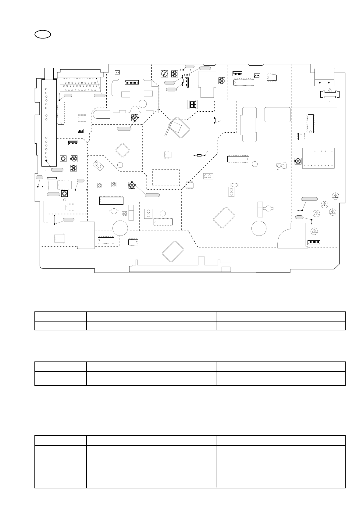
GV 27 …, GV 47 …, GV 7… Adjustment Procedures
GB
Adjustment Procedures
1. Chassis Board (QMB)
SCL
9005
11
1
C
B
A
11
1
2
3
5
6
TUNER
20
&
MODUL.
STV6400
(TUMOD)
1701
11
40,4MHz
17
HF-AFC
1720
1
1
28 15
40,4MHz
FRONT-
END
(FV)
9038
NICAM (QNIC)
110
20 11
21
20
21
20
SDA
9007
10
1
7507
5721
7720/7721
TDA98xx
16 9
5VASW
STEREO
TDA9840
7780
EURO-AV1 / Scart 1
EURO-AV2 / Scart 2
IN/OUT (IO)
1
1711
Band I / PLL
3748
14
AFC
5725
1
8
HEF4053
7722
HEF4053
7513
1
16 9
1710
1
AGC
3742
AFC
9095
1
2
1
2
Audout
HEAD-AMP.
8
AUDIO-FM
(AF)
12
TAE
7461
CLOCHE
ANTI-CLOCHE
5103
5100
7110
32 17
TDA4722
116
SECAM L
(VS-S)
VPS/PDC (VP)
1418
CLOCHE
7
1
1962
(HA)
PAL-Curr.
TDA9604
7850
1
ANTI-
1915, 1916
PAL
Curr.
24
SEC-Curr.
5208
33
3159
7890
24C08
1
3007
14
65
BIAS R BIAS
5603
BIAS-2
BIAS-1
65
VIDEO SIGNAL
PROCESSING
(VS)
17
14 8
FOLLOW TV
(FM)
SEC-Curr.
WTL
7465
24
LC74781
7800
DISPLAY
TMP87CS71F
CONTROL
(DC)
1
3618
999
QQP
LC89980M
7003
13
12
7201/7210
HEAD
GNDAL
9034
9154
3606
1
85
4
1
1
LA71520F
7007
25
41
16 7
14 8
25
41
5001
LM339
7860
3031
5VASW
LED
6460
1
1930
PB-
LEVEL
18 10
3160
19
Lum. Ampl.
check
7460
9
SAA1310
FTA
7466
WTR
7464
20
TMP91C642
7400/7401
33
52
1944
1
TDA5241
7300
1
1810
85
1
1
DECK ELECTRONIC
(DE)
INIT
1480
4
1353
T1,25A
7354
MC44603P
8189
TAS
7462
1
1
SOC1012T
+5V
3379
1
46
17
Transformer
5353
10111 12 13 14 15 16 17 18
POWER
SUPPLY
9071
TRIV
(PS)
SWIN (HP1)
T100mA
9070
1945
1350
1351
T500mA
1352
T500mA
1356
T1A
1355
T1A
65
1.1 Chassis Board – Power Supply (PS)
Test equipment: Digital Voltmeter
Adjustment Preparation Adjustment Procedure
1. +5V, R3379 Adjust voltage to 5.3V ±0.03V with R3379.Digital voltmeter:........................ wire bridge 9038 (5VASW)
1.2 Chassis Board – Keyboard Control Unit (DC)
Test equipment: Frequency Counter
Adjustment Preparation Adjustment Procedure
1. Clock Observe the instructions for Level 53 (see page 2-5).
Call up the Service Test Programme (see page 2-4).
Call up Level 53 (see page 2-4).
Terminate the Service Test Programme (see page 2-4).
1.3 Chassis Board – Deck Control / Deck Electronic (DE)
Test aids: Test Cassette, branded Video Cassette
Service work after changing the …
… Headwheel: Adjustment no. 1, 3
… IC7890: Adjustment no. 1, 2, 3; Keyboard Control Unit: Adjustment no. 1, Frontend: Adjustment no. 4, 5; Standard Sound: Adjustment no. 2
(only for stereo VCR)
Adjustment Preparation Adjustment Procedure
1. Headwheel Position
Indicator
2. VCR Option Code
Call up the Service Test Programme (see page 2-4).
Call up Level 51 (see page 2-4).
Call up the Service Test Programme (see page 2-4).
Call up Level 40 (see page 2-4).
3. Automatic Contour
Control (Option)
Call up the Service Test Programme (see page 2-4).
Call up Level 52 (see page 2-4).
GRUNDIG Service 3 - 3
Observe the instructions for Level 51 (see page 2-5).
Terminate the Service Test Programme (see page 2-4).
Enter VCR option code (see Level 40, see page 2-5).
Terminate the Service Test Programme (see page 2-4).
Observe the instructions for Level 52 (see page 2-5).
Terminate the Service Test Programme (see page 2-4).
k
Page 20

Adjustment Procedures GV 27 …, GV 47 …, GV 7…
1.4 Chassis Board – Frontend (FV)
Test equipment: Oscilloscope with 10:1 Test Probe, Voltmeter, AF Millivoltmeter, Colour Generator
Service work after replacing the
… Tuner, IC7720, IC7721: Adjustments no. 2
… IC7720 (TDA9800T): Remove R3748
… IC7780: Adjustments no. 4, 5
Adjustment Preparation Adjustment Procedure
1. Demodulator Circuit
Voltmeter: ................................. IC7720-(15) or IC7721-(20)
EE-mode.
PAL, F5725
SECAM-L,
R3748 (Band I)
2. Delayed AGC
Voltage,
R3742 (AGC)
(AFC)
Colour generator 38.9MHz - 500mV
Colour generator 33.9MHz / 500mV
Press button "SYSTEM" repeatedly until "SEC" is displayed.
Feed in a PAL white test pattern with sound carrier (without sound
modulation, Ch27, 74dBµV aerial signal) into the warmed-up VCR.
Oscilloscope: .............................................. Tuner 1701-(17)
EE-mode.
3. Residual Carrier
Band I,
F5721 (40.4MHz)
4. Stereo Level
Colour generator 40.4MHz - 300mVPP: ...... Tuner 1701-(17)
Oscilloscope: ........................................................ F1720-(1)
EE-mode.
Call up the Service Test Programme (see page 2-4).
Call up Level 60 (see page 2-4).
5. Cross Talk
Call up the Service Test Programme (see page 2-4).
Call up Level 61 (see page 2-4).
(PLL). The new TDA9800T automatically sets a "Default" value.
: ...... Tuner 1701-(17)
PP
: ...... Tuner 1701-(17)
PP
Set the voltage with F5725
Set the voltage with R3748
Set the amplitude with R3742 (AGC) to 550mVPP +0/-50mV.
Set the amplitude with F5721 (40.4MHz) to minimum (5dB
lower at least than the input signal).
Observe the instructions for Level 60 (see page 2-6).
Terminate the Service Test Programme (see page 2-4).
Observe the instructions for Level 61 (see page 2-6).
Terminate the Service Test Programme (see page 2-4).
(AFC) to 2.5V ±0.2V.
(Band I) to 2.5V ±0.2V.
1.5 Chassis Board – Video/Chroma (VS, VS-S)
Test equipment: Oscilloscope with 10:1 Test Probe, Colour Generator
Service work after replacing the IC7007 or 7110: Adjustment no. 1
Adjustment Preparation Adjustment Procedure
1. Chroma Recording
Current
Remove the drive mechanism (see page 1-9)
Call up the Service Test Programme – Level 10 (see page 2-4)
Feed in a PAL red raster test pattern with 75% saturation (ratio
The FMF signal must have an amplitude of 420mVpp. If the
value deviates by more than ±40mV
defect (e.g. IC7007).
burst: chroma = 1 : 2.2) into the AV1 socket and record it.
Oscilloscope: ................................ R3031 (T7006 – Emitter)
Connect R3031 (T7006 – Emitter) to L5001 (5VASW).
PAL,
R3007
(PAL-Curr.)
Oscilloscope: ................................................ R3007 – wiper
Feed in a PAL red raster test pattern with 75% saturation (ratio
Set Chroma signal with R3007 (PAL-Curr.) to 160mVPP ±20mV
(for 2-Head-VCR) or 130mVPP ±20mVPP (for 4-Head-VCR).
burst: chroma = 1 : 2.2) into the AV1 socket and record it.
SECAM-L,
R3159 (SECAM-Curr .)
Oscilloscope: ................................................ R3159 – wiper
Feed in a SECAM-L red raster test pattern with 75% saturation
(ratio burst: chroma = 1 : 2.2) into the AV1 socket and record
it.
Set Chroma signal with R3159
±30mV
.
PP
Terminate the Service Test Programme, disconnect R3031
from L5001 and reassemble the drive mechanism.
1.6 Chassis Board – Standard Sound (AL)
Test equipment / aids: Frequency Counter, AF Millivoltmeter, AF Generator, Colour Generator, branded Video Cassette.
Service work after replacing the RP-Head, L5603 or IC7007: Adjustment no. 1, 2
Adjustment Preparation Adjustment Procedure
1. Erase Frequency,
F5603
(BIAS R)
1.1 Bias, R3618 (BIAS)
1.2 Frequency
Response Test
2. Playback Level for
Mono VCR,
R3160 (PB-Lev.)
for Stereo VCR
Frequency counter: ....................... wire bridge 9034 (Head)
Record
AF millivoltmeter:.......................... BIAS1 or BIAS2 (R3606)
Record.
–Feed in a CCVS signal via EURO-AV1 socket, contact 20.
–Feed an audio signal of 200mV
generator to the EURO-AV1 socket, contact 2 or 6.
(480mVPP) from the AF
rms
–Make a recording of 400Hz and 8kHz each of 1 min at least.
Afterwards play back these recordings (MONO).
–Connect an AF millivoltmeter (oscilloscope) to EURO-AV1
socket, contact 1 or 3.
AF millivoltmeter:............ EURO-AV1 socket, contact 1 or 3
AF generator (1kHz / 0.7V
........................................EURO-AV1 socket, contact 2 or 6
):
rms
Feed in a CCVS signal via EURO-AV1 socket, contact 20.
Play back the self made recording (Normal Play).
Call up the Service Test Programme (see page 2-4).
Call up Level 62 (see page 2-4).
With F5603 (BIAS R) set the frequency to 70kHz ±10kHz.
Set the voltage drop across R3600 with R3618 (BIAS) to
15mV
.
rms
Check the frequency response.
The voltage ratio of 400Hz to 8kHz must not be higher than
1:0.7 or 0.7:1 (±3dB). If the voltage ratio exceeds these limits,
the bias must be altered:
To increase the playback voltage at 8kHz: Reduce "BIAS".
To reduce the playback voltage at 8kHz: Increase "BIAS".
Set output voltage with R3160 (PB-Lev.) to 0.5V
Observe the instructions for Level 62 (see page 2-6).
Terminate the Service Test Programme (see page 2-4).
there is a technical
pp
(SECAM-Curr.) to 210mV
±50mV.
rms
PP
PP
3 - 4 GRUNDIG Service
k
Page 21

GV 27 …, GV 47 …, GV 7… Platinenabbildungen und Schaltpläne / Layout of PCBs and Circuit Diagrams
Platinenabbildungen und Schaltpläne / Layout of PCBs and Circuit Diagrams
Abkürzungen / Abbreviations
Signal Abkürzungen Abbreviations Verwendung / Application
+5AS +5V Analog nach Sicherung 1700 +5V analog after fuse 1700 QNIC
+5ASS +5V Analog nach Drossel 5706 +5V analog after coil 5706 QNIC
+5D +5V Digital +5V digital DE QNIC
-28V -28V für Display -28V for display DC IO PS
-7V -7V für "IN/OUT" -7V for "IN/OUT" IO
12SW +12V Analog, (< 6W geschaltet) +12V analog, (<6W switched) AL FV PS QNIC
12VA +12 Analog +12V analog AF FV IO PS
14VM1 +14V für Fädel- und Kopfradmotor +14V for threading and head motor DE PS
2FSC Doppelte Farbhilfsträgerfrequenz Double colour subcarrier frequency OS VS
33V +33V für Tunerabstimmung +33V tuner adjustment FV PS
5VA +5V Analog +5V analog AF FV IO OS PS
5VASW +5V Analog (< 6W geschaltet) +5V analog (< 6W switched) DE FV HA OS PS QNIC VS VS-S
5VASW2 +5V Analog nach Drossell 5802 +5V analog after coil 5802 OS
5VASWB +5V Analog nach Drossell 5726 +5V analog after coil 5726 FV
5VD +5V Digital +5V digital DC DE FV PS
5VD1 +5V Digital nach Drossel 5200 +5V digital after coil 5200 DC
5VD2 +5V Digital nach Drossel 5400 +5V digital after coil 5400 DE
8SC1 Scart 1 Pin 8, Ausgang Scart 1 pin 8, output DE IO
8SC2 Scart 2 Pin 8, Eingang Scart 2 pin 8, input DE IO
9/14VM2 Capstanmotor Versorgung, geschaltet Capstan motor supply, switched DE PS
AEH 1/2 Audio Löschkopf Audio erase head AL
AF FM-Ton FM sound
AF1 Audio links vom Stereodecoder Audio left from stereo decoder AF AL FV IO
AF2 Audio rechts vom Stereodecoder Audio right from stereo decoder AF FV
AFC Automatische Frequenzkontrolle Automatic frequency control DC FV
AFE Audio von der Empfangseinheit Audio from Frontend FV IO QNIC
AGC Automatische Verstärkungsregelung Automatic gain control DE FV
AH1/2/C Audioköpfe Audio heads HA
AIN1 Audio Eingang von Scart 1 Audio input scart 1 AL IO
AIN1L Audio Eingang von Scart 1, links Audio input scart 1, left AF IO
AIN1R Audio Eingang von Scart 1, rechts Audio input scart 1, right AF IO
AIN2 Audio Eingang von Scart 2 Audio input scart 2 AL IO
AIN2L Audio Eingang von Scart 2, links Audio input scart 2, left AF IO
AIN2R Audio Eingang von Scart 2, rechts Audio input scart 2, right AF IO
AINFL Audio links von der Frontbuchse Audio left from front socket AF IO
AINFR Audio rechts von der Frontbuchse Audio right from front socket AF IO
AL Standardton Standard Sound
AMCO Audio zum Modulator Audio to the modulator AF FV
AMLP Audio "Mono" Wiedergabe Audio "mono" playback AF AL FV IO
AMLR Audio "Mono" Aufnahme Audio "mono" record AF AL IO
AN1/2 Analogspannung der Tastenmatrix Analog voltage of keyboard matrix DC
ANIL Audio "NICAM", links Audio "NICAM", left FV QNIC
ANIR Audio "NICAM", rechts Audio "NICAM", right FV QNIC
AOUT1L Audio Ausgang von Scart 1, links Audio output from scart 1, left AF IO
AOUT1R Audio Ausgang von Scart 2, rechts Audio output from scart 2, right AF IO
AOUT2L Audio Ausgang von Scart 2, links Audio output from scart 2, left AF IO
AOUT2R Audio Ausgang von Scart 2, rechts Audio output from scart 2, right AF IO
APH Audio Wiedergabekopf Audio playback head AL
ARH Audio Aufnahmekopf Audio record head AL
BLANKING Austastimpuls (für RGB-Durchschleifsignal) Blanking pulse (for RGB loop-through signal) IO
BLUE Blau Signal zwischen Scart 1/2 Blue signal between scart 1/2 IO
CAP Capstan Steuerspannung Capstan control voltage DE
CKDET Farbsystem Information Colour system information DE VS
CLKD1 Serieller Bus (Clock) Serial bus (clock) DC DE
CREV Capstan "Reverse" Capstan "reverse" DE
CROT Farbphasenrotation "Ein/Aus" Colour phase rotation "on/off" DE VS
CSCP Farbphasenumschaltung im LP-Betrieb Colour phase change in LP mode DE VS
CSI Farbsystem Information Colour system information DE VS-S
CSP Chroma-Wiedergabesignal "SECAM" Chrominance playback "SECAM" VS VS-S
CSR Chroma-Aufnahmesignal "SECAM" Chrominance record "SECAM" HA VS-S
CSW 8V/14V Unschaltung für Capstan Motor 8V/14V switching for capstan motor DE PS
CSYNC/1/2 Synchron-Signalgemisch Composite sync pulse DE HA OS VS VS-S
CTL1/2 Signal von der Kontrollspur (CTL) Control track signal (CTL) AL DE
DATD1/2 Daten vom seriellen Bus Serial bus data DC DE
DC Bedieneinheit Keyboard Control Unit
DE Laufwerksteuerung / Deck Elektronik Deck Control / Deck Electronic
DEC Audio-Umschaltung Audio switching voltage IO
ENVC Hüllkur ven Vergleichsignal Envelope comparator signal DE HA
FFP Künstlicher Bildimpuls Artificial frame pulse DE VS
FG/FGD Capstan Tachoimpulse Capstan tacho pulse DE
FM Follow TV Follow TV
FMAP FM Audio Wiedergabe FM audio playback AF HA
FMAR FM Audio Aufnahme FM audio record AF HA
FMPV FM Video-Wiedergabe FM video playback HA VS VS-S
FMRV FM Video-Aufnahme FM video record HA VS
FOME Follow TV-Signal (Videosignale identisch) Follow TV signal (video signals identical) DE FM
GRUNDIG Service 4 - 1
Page 22

Platinenabbildungen und Schaltpläne / Layout of PCBs and Circuit Diagrams GV 27 …, GV 47 …, GV 7…
Signal Abkürzungen Abbreviations Verwendung / Application
FTA/FTAD Fädeltacho Threading tacho DE
FV Empfangseinheit Frontend
GNDA Masse Analog Ground analog FV IO QNIC
GNDA1/A2 Masse Analog "NICAM" Ground analog "NICAM" QNIC
GNDAF Masse Analog "FM-Ton" Ground analog "FM Sound" AF
GNDAIO Masse Analog "IN/OUT" Ground analog "IN/OUT" IO
GNDAL Masse Analog "Standardton" Ground analog "Standard Sound" AL
GNDD Masse Digital Ground digital AF DE IO QNIC
GNDEO Masse Löschoszillator Ground erase oscillator AL
GNDM Masse für Motoren Ground capstan motor DE
GNDVS Masse Signalelektronik Ground Signal Electronics AF
GNDVSIO Masse Analog "Video, IN/OUT" Ground analog "Video, IN/OUT" IO
GREEN Grün Signal zwischen Scart1/2 Green signal between scart1/2 IO
HA Kopfverstärker Head amplifier
HEHI Display-Heizung (HIGH) Display heater (HIGH) DC PS
HELO Display-Heizung (LOW) Display heater (LOW) DC PS
HEST Heizungsspannung - Steuersignal Heater voltage control signal DC
HP2 Kopfumschaltimpuls Audio Head pulse audio AF DE HA
I/R INIT-Schalter / Aufnahmesperre INIT switch / record prodection DE
ILED Steuerspannung für Bandanfang/ende-Sendediode Switching voltage for start/end of tape transmitting diode DE
INIT Initialisierungsschalter für das Laufwerk Initialisation switch for Deck Mechanism DE
IO IN/OUT IN/OUT
IPOR Reset bei Inbetriebnahme (Invertiert) Power-on reset (inverse) DC DE
IRAF Schaltspannung bei FM-Audio-Aufnahme "LOW" Switching voltage for FM audio record "LOW" DE HA
IREV Dubbing Oszillator Ein/Aus Dubbing oscillator on/off AL DE VS
ISTBY Schaltspannung bei STANDBY "LOW" Switching voltage for Standby "LOW" DC PS
ISWS Video-FM Mute Video-FM mute DE VS
IWIND Kontrollimpulse Verstärkung Control pulse amplification DE
LH1/2/C Longplay Köpfe Longplay heads HA
MEH1/2 Hauptlöschkopf Main erase head AL
MON Monitor Durchschleifsignal Scart 1/2 Monitor loop-through scart 1/2 IO
MOT0-3 Kopfmotor Steuerleitungen Head motor control lines DE
MTA Audio-Stummschaltung Audio mute AL DE
NC Nicht verwendet Not connected DE
OCLK OSD-Bus (Clock) OSD bus (clock) DC OS
OCS OSD-Chip Select OSD chip select DC OS
ODAT OSD-Bus (Daten) OSD bus (data) DC OS
OFP Bildimpuls Frame pulse DE OS
OS OSD OSD
PBV Wiedergabe-Schaltspannung Playback switching voltage DE VS-S
PG/FG Kopfscheibenposition/Geschwindigkeit Headwheel position/speed DE
POS Kopfscheibenposition Headwheel position DE
PS Netzteil Power Supply
PSS PAL oder SECAM-L PAL or SECAM-L DC FV
QMB Chassisplatte Family Board
QNIC NICAM-Decoder NICAM Decoder
RECP Aufnahmesperre Record protection DE
RED Rot-Signal zwischen Scart 1/2 Red signal between scart 1/2 IO
REEL Kopfscheibenmotor-Steuerspannung Headwheel motor control voltage DE
SB1 SECAM Band 1 SECAM band 1 DC FV
SCL I2C Bus - Takt I2C bus clock AF DC FV IO OS QNIC
SCL2 Serieller Bus - Takt Serial bus clock DE VS
SDA I
SDA2 Serieller Bus - Daten Serial bus data DE VS
SFS Schaltspannung für ZF-Tonfilter Switching voltage for IF sound filter DC FV
SH1/2/C Standard play Köpfe Standard play heads HA
SSIF Zweiton Zwischenfrequenz Dual sound intermediate frequency FV QNIC
SWIN Kopfumschaltimpuls Head switching pulse DE HA
SYNC Kontrollimpulse CTL von der Kontrollspur CTL control track pulse DE
TAE Bandende-Erkennung Tape end identification DE
TAS Bandanfang–Erkennung Tape start identification DE
THIO Schaltspannung Einfädeln / Ausfädeln Switching voltage threading in/out DE
TMO Fädelmotor-Schaltspannung Threading motor switching voltage DE
TMO1/2 Fädelmotoranschluß Threading motor connection DE
TRIA/ALI Trackinginformation Audio / Aussteuerungsanzeige Tracking information audio / audio level indication AF DE
TRIV Trackinginformation Video Tracking information video DE HA
VBS Video zur Signalelektronik Video to Signal Electronics FM IO VS
VFR Video von der Frontbuchse Video from front socket IO
VFV Video von der Empfangseinheit Video from Frontend FM FV IO VS
VIN1/2 Videoeingang - Scart 1 / 2 Video input scart 1 / 2 IO
VISS Kontrollspurimpuls Invertierung Control track pulse inversion DE
VMOD Video - Modulator Video - modulator FV IO
VOUT Video von OSD Video from OSD IO OS
VP VPS/PDC VPS/PDC
VREC Video Aufnahme von VS / IO Video record from VS / IO IO VP VS VS-S
VREF Referenzspannung Reference voltage VS-S
VS Video/Chroma (Signalelektronik) Video/Chroma (Signal Electronics)
VS-S SECAM-L (SECAM-VS) SECAM L (SECAM-VS)
VSB Video von der Signalelektronik Video from Signal Electronics OS VS
W/R Synchronspur-Schreiben/Lesen Write/read sync track DE
WTL/WTLD Tachosignal vom linken Wickelteller Wind tacho left DE
WTR/WTRD Tachosignal vom rechten Wickelteller Wind tacho right DE
2
C Bus - Daten I2C bus data AF DC FV IO OS QNIC
4 - 2 GRUNDIG Service
Page 23
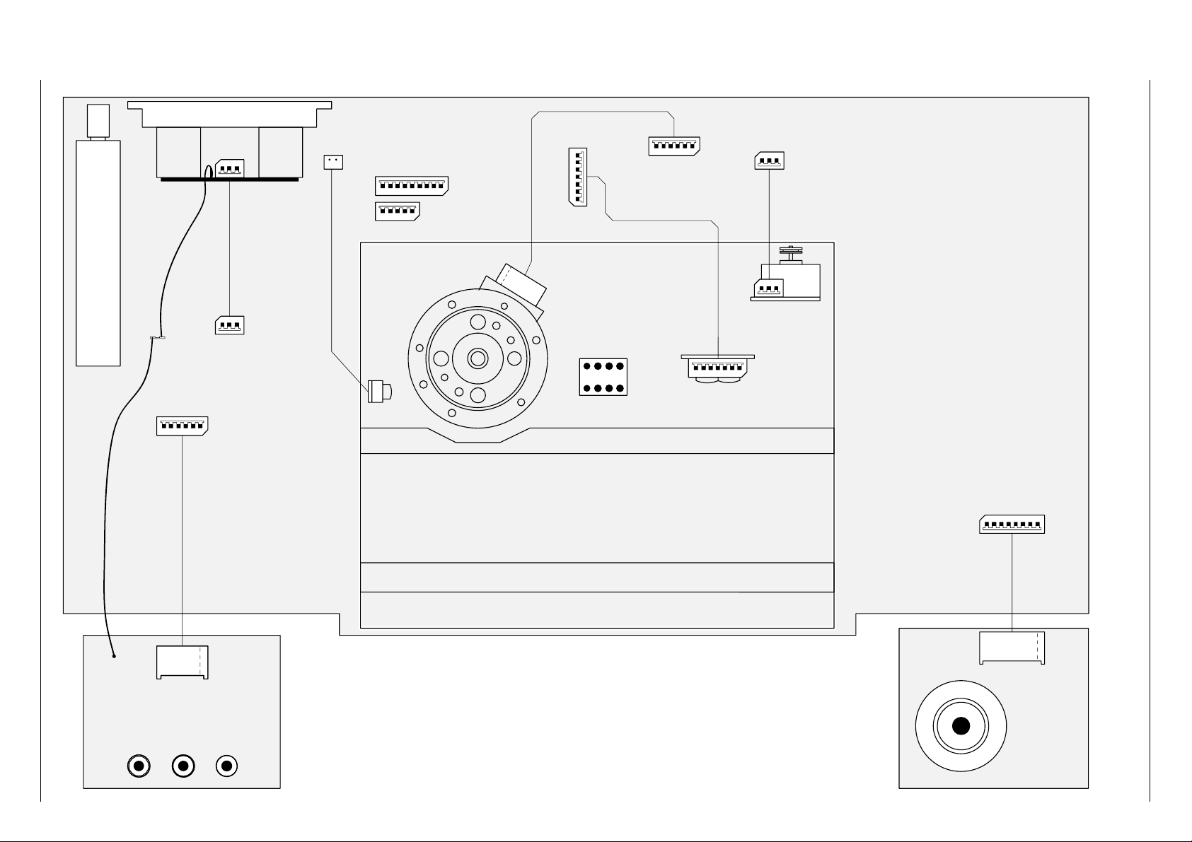
GRUNDIG Service 4 - 3
( # 2645. )
1103
4
3
2
1
5
VID inL inR in
VIDEOAUDIO
1901
6
4
3
2
1
5
SOCKET-Pr.:
6
8004... # 2628.
8001... # 2625.
ARH
1
TD4
Rotating Trafo-Conn.
AH2
AHC
AH1
SH1
SHC
SH2
LH2
LHC
LH1
1915
123456789
1930
M1M3M2
M0
POS
GNDD
12345
6
1-1
6
5
4
3
2
1
GNDD
GNDM2
CREV
FG
+6/16M2
GNDD
+5D
CAP
CAPSTAN-MOTOR-CONN.
1946
567
81
234
TD1(L3)
AUDIO-CONTROL-HEAD
ARH
CTL1
CTL2
AEH1
AEH2
APH
GND
1234567
THREADING MOTOR
ERASE-HEAD
2
1
MEH1
MEH2
TMO1
N.C.
TMO2
M1
M3
M2
M0
POS
GNDD
MOBO-DECK
TD3(L4)
TD2(L8)
1-1
1944
123
1-1
123
1-1
TMO1
N.C.
TMO2
2
3
4
5
6
7
CTL1
CTL2
AEH1
AEH2
APH
GND
8003... # 2627.
1961
12345
1916
2
1
1962
8002... # 2626.
QBOG1
1711
1-1
12VA
GNDVSIO
AINFL
GNDAIO
AINFR
VFR
TUNER + MODULATOR
123
AOUT1R
GNDAIO
AOUT1L
321
7
8
SHUTTLE-Pr.
GND
AN1
5VD
SHUTTLE b2
SHUTTLE b3
SHUTTLE b1
SHUTTLE b4
AN2
1945
1234567
8
GND
AN1
5VD
SHUTTLE b2
SHUTTLE b3
SHUTTLE b1
SHUTTLE b4
AN2
1-1
12VA
GNDVSIO
AINFL
GNDAIO
AINFR
VFR
1-1
1-1
1-1
AOUT1R
GNDAIO
AOUT1L
MEH1
MEH2
1-1
1-1
8006... # 2642.
8007... # 2627. --> 8003
8005... # 2643.
EURO-AV 1/2 CINCH OUT L/R
1917/1918 1911/1912
1750
1710
8008... # 2646.
12345
6
GV 27 …, GV 47 …, GV 7… Platinenabbildungen und Schaltpläne / Layout of PCBs and Circuit Diagrams
Verdrahtungsplan / Wiring Diagram
Page 24
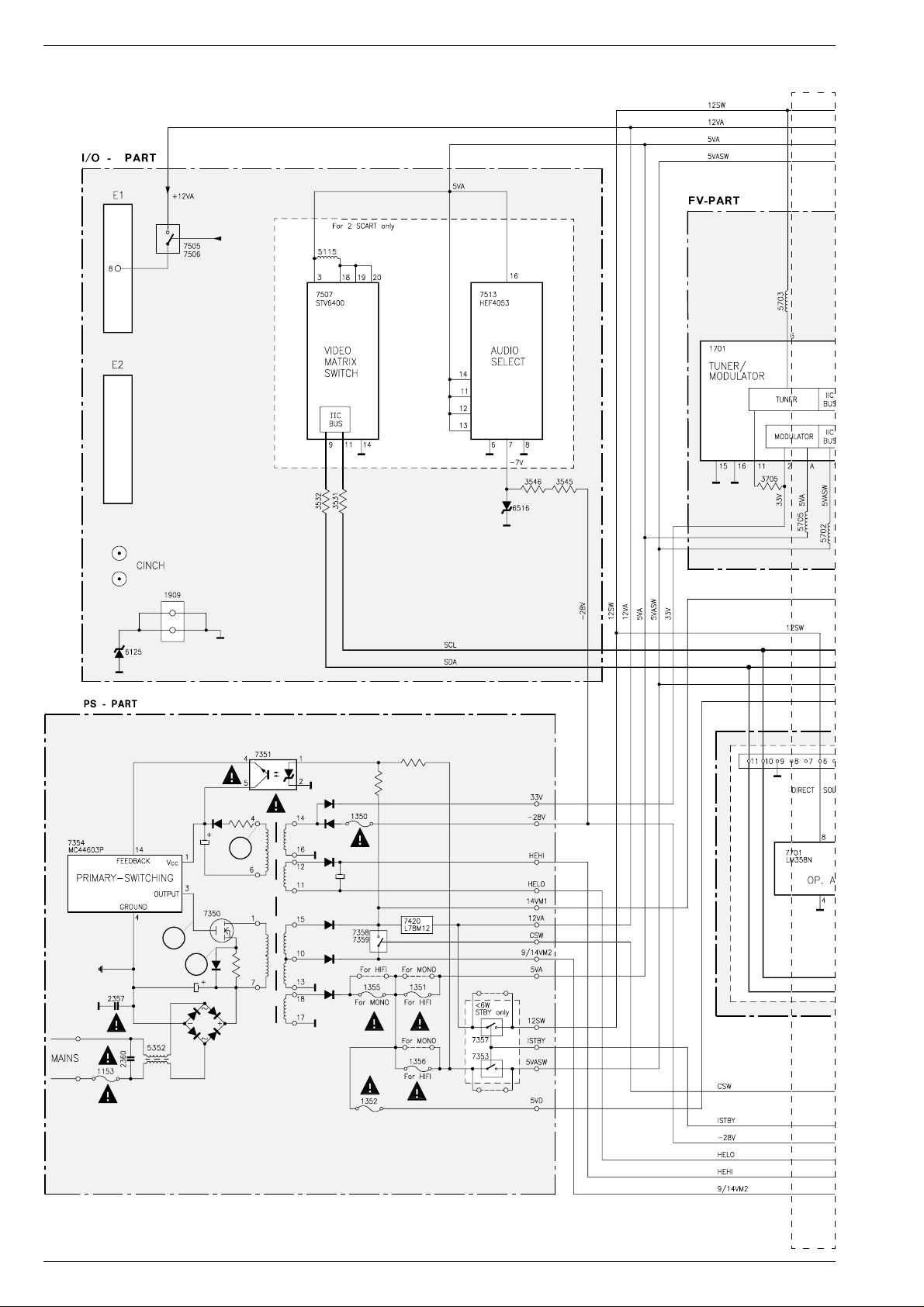
Platinenabbildungen und Schaltpläne / Layout of PCBs and Circuit Diagrams GV 27 …, GV 47 …, GV 7…
Blockschaltplan (Netzteil / Bus-System) / Block Circuit Diagram (Power Supply / Bus System)
EURO-AV
EURO-AV
3
1
2
4 - 4 GRUNDIG Service
Page 25

GV 27 …, GV 47 …, GV 7… Platinenabbildungen und Schaltpläne / Layout of PCBs and Circuit Diagrams
Reference
Oscillograms
....4-38
AF....................4-29
AL....................4-25
DC ...................4-35
DE ...................4-33
FV....................4-21
FM ...................4-24
HA ...................4-30
IO.....................4-27
OS ...................4-24
PS....................4-31
QMB ................4-15
QNIC ...............4-36
VP....................4-24
VS....................4-25
VS-S................4-28
GV 27 …, GV 47 …, GV 7… Platinenabbildungen und Schaltpläne / Layout of PCBs and Circuit Diagrams
GRUNDIG Service 4 - 5
GRUNDIG Service 4 - 6
Page 26

Platinenabbildungen und Schaltpläne / Layout of PCBs and Circuit Diagrams GV 27 …, GV 47 …, GV 7… Platinenabbildungen und Schaltpläne / Layout of PCBs and Circuit Diagrams GV 27 …, GV 47 …, GV 7…
Blockschaltplan / Block Circuit Diagram (Video/Chroma)
EURO-AV2
EURO-AV1
94 852681
60
14
13
62
65
63 18
73
20
4 - 7 GRUNDIG Service 4 - 8 GRUNDIG Service
Page 27

GV 27 …, GV 47 …, GV 7… Platinenabbildungen und Schaltpläne / Layout of PCBs and Circuit Diagrams
12SW 5VASW
5VASWB
SCL2(DE) SDA2(DE)12SW
AIN1
AIN2
AF1
MTA(DE) 12SW
7604
1961/5
TD1/3
1961/4 TD1/4
1962/1 TD2/2
1962/2 TD2/1
1961/1 TD1/7
1961/31961/3 TD1/5
7609
3618
IREV(DE)
5DV1
5DV2
5VA
5VA
-7V
SDA
SDA
(FV)
SCL
(FV)
SCL
IREV
(AL)
SDA2
(AL)
MTA
(AL)
SCL2
(AL)
2
14 13 15,16
24
15
26,43,57
8
2
3610
11 10
6 A 12 20
63 6476 70
A-VCC MUTE
A-GND
HD
SW
33
75
33 6058
56
3
16
7
9
11
29 59
23
-
mute
Erase
Osc.
Serial-Bus
Control
Display
Controller
Deck
Controller
LA71525M
Linear-Aud. Proc.
Mute
ALC
Rec-Amp
EQ-Amp
Line
TDA 9800T Demod.
7720
1701
7007
BIAS
Audio Erase
Head
Main Erase
Head
REC/PB
Head
Front end (FV)
Deck Electronics (DE)
In/Out (IO)
Display Control (DC)
Linear-Audio (AL)
Tape Deck
7201
7400
TUMOD
33V
5,5MHz(BG)
6.0MHz(I)
6,5MHz(DK)
SDA
(DC)
SCL
(DC)
5VA
7725
AF1
91118
1720
1745
17 1
2
3
7371 75
77
1
7
5
6
79
PB
REC
REC
PB
REC
7600
7601
7602
PB
AMLP
AMLP
26
38
40
39
27
31
EURO-AV1
EURO-AV2
1917
7513
7507
7510
7512
1918
2
2
1
1
6
AIN1
AIN1
AF1
AIN2
AIN2
AMLP
5
4
9
7
MON
DEC
10
5
15
3
2
1
6
3
3
Video
Input Sel.
STV6400
HEF4053
GV 27 …, GV 47 …, GV 7… Platinenabbildungen und Schaltpläne / Layout of PCBs and Circuit Diagrams
61
Reference
Oscillograms
AF....................4-29
....4-38
AL....................4-25
DC ...................4-35
DE ...................4-33
FV....................4-21
FM ...................4-24
HA ...................4-30
IO.....................4-27
OS ...................4-24
PS....................4-31
QMB ................4-15
QNIC ...............4-36
VP....................4-24
VS....................4-25
VS-S................4-28
Blockschaltplan (Standardton) / Block Circuit Diagram (Standard Sound)
GRUNDIG Service 4 - 9
GRUNDIG Service 4 - 10
Page 28

Platinenabbildungen und Schaltpläne / Layout of PCBs and Circuit Diagrams GV 27 …, GV 47 …, GV 7… Platinenabbildungen und Schaltpläne / Layout of PCBs and Circuit Diagrams GV 27 …, GV 47 …, GV 7…
Reference
Oscillograms
....4-38
AF....................4-29
AL....................4-25
DC ...................4-35
DE ...................4-33
FV....................4-21
FM ...................4-24
HA ...................4-30
IO.....................4-27
OS ...................4-24
PS....................4-31
QMB ................4-15
QNIC ...............4-36
VP....................4-24
VS....................4-25
VS-S................4-28
Blockschaltplan (FM-Ton) / Block Circuit Diagram (FM Sound)
Front end (FV)
12SW
5VASW
33V
5VA
A12 26 181
2
6
26
1719
17 28
1701
TUMOD
5VASWB 5VASW
7721
27
17
SFS
(DC)
7722
HEF
4053
5,5MHz
5,74MHz
15
6,5MHz
BG
6,25MHz
DK
14 11
31
14 13 15,16
SDA
SCL
(DC)
(DC)
3
SSIF
AMCO
SDA
(DC)
SCL
(DC)
TDA 9813,9814 Demod.
24
5VASW
101
7700
29
50
49
SAA 7284ZP
11
36
NICAM
1975
4
1
2
NICAM (QNIC)
12SW5VD
46 7,16
DEC.
AFE
5
610
4
102
7
15
9
8
Socket PCB In/Out (IO)
1103/3
FrontRear
CINCHCINCH
1103/1
1171/3
1171/1
L
R
AINFL
AINFR
98
1750/1
1917
6
2
3
EURO-AV1EURO-AV2
1
1918
6
2
1750/3
1710/1
1710/3
99
L
R
AIN1L
AIN1R
AOUT1L
AOUT1R
AIN2L
AIN2R
97
90
89
3
1
AOUT2L
AOUT2R
AMCO
Deck Electronics (DE)Display Control (DC)
HP2
MTA
(AL)
IRAF
(HA)
29 59
SCL2
(AL)
SDA2
(AL)
54
SFS
SDA
(FV,AF)
SCL
(FV,AF)
23
(FV)
5DV1
33 31 75
7201 7400
Display
Controller
15 26,43,57
(AF,HA)
5DV2
56
IREV
(AL)
1958
33 38 60
Deck
Controller
10
27
7
8
ANIL
ANIR
TRIA/ALI
SDA
(DC)
7780
TDA 9840
STEREO
DEC.
910
LLR
3
4
5
6
7
8
9
10
15
16
11
39
SCL
(DC)
20
14
13
Source Sel.
16
LineSel
EXT2
OutSel
DecoderSel
EXT1
TUNER
OutSel
AFC
18,27
FM-Audio (AF) Head Amplifier (HA)
AF1
AF2
SDA
12VA
5VA 5VASW
35
38 1
(DC)
SCL
(DC)
41
42 10
91
SUPPLY
R
IIC-Bus
Control
HP2
(DE)
40 39
TRIA/ALI
(DE)
7080
STV 5712
Head Ampl.
InputSel
1
2
TUNER
CINCH
EXT1
EXT2
EXT3
SAP
Lin.Audio Sel
L+R
L+R x Volume
L
R
L x Volume
Volume L/R
+15dB
-48dB
mute
REC
FM Audio
Processing
FMAR
36 11
96
FMAP
37
95
8
6,169 2,415
HP2(DE)
1915/1
PB
TDA 9604H
FM-Audio Processing
Mute
mute
Env-Sel
L
R
STEREO
-
OutSel
OutputSel
STEREO
LEFT
RIGHT
NORMAL
NOR+ST
NOR+L
NOR+R
mute
Level
+15dB
0dB
mute
93
REC
17
SCL2(DE) SDA2(DE)12SW
73
A-VCC MUTE
ALC
19
77
63 6476 70
Serial-Bus
Control
REC
PB
Rec-Amp
92
79
REC
A-GND
2
11 10
3610
MTA(DE) 12SW
LA71525M
Linear-Aud.
Processing
Line
EQ-Amp
Mute
-
mute
PB
REC
IREV(DE)
7007
7604
7609
Erase
1961/5
Osc.
38
1961/4 TD1/4
1962/1 TD2/2
1962/2 TD2/1
1961/1 TD1/7
1961/31961/3 TD1/5
7600
7601
7602
BIAS
3618
1
7
5
PB
6
HD
SW
Linear-Audio (AL) Tape Deck
Head Drum
TD1/3
VCC
1915/2
IRAF
(DE)
7085
1
REC
REC
1915/3
Audio Erase
Head
Main Erase
Head
REC/PB
Head
1
14
4 - 11 GRUNDIG Service 4 - 12 GRUNDIG Service
Page 29

GV 27 …, GV 47 …, GV 7… Platinenabbildungen und Schaltpläne / Layout of PCBs and Circuit Diagrams
Reference
Oscillograms
....4-38
AF....................4-29
AL....................4-25
DC ...................4-35
DE ...................4-33
FV....................4-21
FM ...................4-24
HA ...................4-30
IO.....................4-27
OS ...................4-24
PS....................4-31
QMB ................4-15
QNIC ...............4-36
VP....................4-24
VS....................4-25
VS-S................4-28
Blockschaltplan / Block Circuit Diagram (Digital)
GV 27 …, GV 47 …, GV 7… Platinenabbildungen und Schaltpläne / Layout of PCBs and Circuit Diagrams
GRUNDIG Service 4 - 13
GRUNDIG Service 4 - 14
Page 30

Platinenabbildungen und Schaltpläne / Layout of PCBs and Circuit Diagrams GV 27 …, GV 47 …, GV 7… Platinenabbildungen und Schaltpläne / Layout of PCBs and Circuit Diagrams GV 27 …, GV 47 …, GV 7…
Reference
Oscillograms
....4-38
AF....................4-29
AL....................4-25
DC ...................4-35
DE ...................4-33
FV....................4-21
FM ...................4-24
HA ...................4-30
IO.....................4-27
OS ...................4-24
PS....................4-31
QMB ................4-15
QNIC ...............4-36
VP....................4-24
VS....................4-25
VS-S................4-28
Chassisplatte / Chassis Board (QMB)
Ansicht von der Bestückungsseite / View of Component Side
1 2 3 4 5 6 7 8 9 1011121314151617 18
Line-Buchsen-Platte
Line Socket Board
A
C
B
B
A
1
2
9005
9198
3
5
6
11
17
2740
C
D
E
F
G
SCL
H
I
J
K
L
1975
NICAM
9197
1101
1 2 3 4 5 6 7 8 9 1011121314151617 18
1116
1102
2780
1117
9000
9032
1719
2742
9178
1103
1118
9251
1701
20
9019
5115
1722
1721
1720
FRONTEND
9028
9035
2744
1740
9038
2784
5780
STEREO
1781
1105
1106
1104
1121
1122
1120
21
21
9010
20
6501
SDA
6510
9007
9200
6500
1011
9185
7507
9184
1
9083
2514
5705
2704
5702
19081910
2708
40,4
5720
5721
2750
9086
AFC
5725
9042
5740
9246
5VASW
2792
2786
1107
1108
1110
1109
1119
1123
1124
6511
3521
IN-OUT
6509
9231
9203
9230
9196
1
1711
5703
AGC
3742
3748
PLL
2727
AFC
1746
1745
5741
9218
9026
9031
9029
2787
1111
1113
1127
1125
1126
6502
9229
1
2796
1917
1710
1918
9082
9152
1747
1748
9097
9033
1131
9202
9126
9172
1153
9036
9145
1132
3518
3538
2503
9024
3513
9128
9162
9248
9201
9080
2728
9018
9027
9008
1134
3514
3517
3539
9284
9220
9236
9014
2873
3537
2872
9053
9051
9244
7461
9247
9016
9048
9095
ANTICLOCHE
9096
1135
1136
1154
9182
1
9180
9204
2
9228
9049
2502
9232
9183
9012
2875
2874
9094
0020
TAE
3107
3109
3106
5102
5100
5101
3100
3102
32
1
5111
5114
VPS/PDC
14
7540
1
9022
9023
1141
1140
1156
1155
1157
6516
9058
9150
9011
9192
2877
2876
AUDIO-FM
3103
CLOCHE
5106
7110
5107
5112 5113
3233
1142
1143
1158
1159
1160
1962
1
9233
9260
9087
9078
9186
9234
0060
9227
SECAM-SE
3105
3104
5103
5105
3110
17
16
0030
3115
ANTICLOCH E
8
9050
7
9506
1144
1146
1145
1162
1163
1161
1164
HEAD-AMPL.
9212
9013
AGC
1
1916
1915
0050
0051
2152
9211
3007
9208
9207
PALCURR
2866
2867
9241
2854
2870
2852
2850
9226
SEC-
5104
CURR
6100
3159
3111
3123
RECP
3124
5108
1461
9046
3473
7890
58
9223
9075
3232
1147
1148
1149
3231
3453
9530
9131
1165
9176
3118
3479
1
3120
14
9179
9238
9187
9268
9125
3454
3472
9235
3117
5200
9037
5150
3238
2086
2871
9165
9300
9177
9133
9222
9259
9093
9209
9191
2211
9055
9413
9052
9149
9285
9148
9146
9054
7465
9269
6299
9084
9194
9169
3025
9206
9168
WTL
5080
9210
9081
9225
1
9105
3023
9156
9193
9157
FOME
9151
2804
0007
24
1
2297
9144
1297
3234
9501
2881
2620
5603
2619
2617
3006
6601
2652
3033
2049
3027
3656
3528
999
9155
2039
3017
VIDEO-SE
5831
9504
2880
2888
9174
9219
9112
9079
5810
OSD
0061
7800
5800
9124
3235
1298
13
DISPLAY-
CONTROL
HEST
BIASCURR
2622
3618
C
2602
B
E
7604
2648
9171
AUDIOLINEAR
QQP
9502
9175
9006
9170
1324
12
9519
2805
5604
9224
5802
2651
5601
2032
2043
9243
3052
9288
7202
IC
2059
2054
9073
9505
9289
3604
9801
BIAS-2
3606
9092
9021
2041
5801
9127
9034
9154
BIAS-1
9089
3600
2021
2025
3457
9290
HEAD
GNDAL
9098
1961
5602
1
8
5
1946
14
9250
2014
9510
3570
9237
9517
9520
9515
6250
9503
9409
9514
9522
9406
3022
9401
9407
2017
2010
9521
9114
3021
9004
2019
2020
9283
5402
9103
2044
2005
9516
9518
LED
9102
2460
2604
2012
9509
3432
5001
3451
5002
3424
9213
9411
9065
9414
9412
9512
9101
5005
9039
9205
3401
5400
3411
0021
9147
9129
6460
9415
9418
9163
3417
3251
9111
9507
9242
3402
2401
5026
9513
3416
3460
3253
3005
3045
5000
5000
3483
9104
9110
3252
3302
3303
9099
2302
3160
PB-
LEVEL
9199
9009
3003
3002
3031
3050
3030
3008
9166
9511
9286
9061
9159
9062
C
B
7463
E
9287
9189
9118
3436
3304
9416
3499
3400
DECK-
CONTROL
9100
3228
9195
3254
9057
3475
9143
3435
9132
9134
9160
5004
9437
9106
WTR
3471
2220
7203
9017
3404
3018
3470
9141
3407
9282
2300
3004
3046
5020
9137
9221
9438
9217
9436
9435
9161
3484
9
10
9142
7464
3452
3463
3406
9402
5036
1
9113
7466
9164
3300
3491
9403
1930
9420
0008
SOLDERDIRECTION
9252
3430
1170
1197
9091
3480
3489
9107
9108
3408
3437
9405
3301
3403
3455
1171
1198
7300
3265
9423
1750
3412
1199
3477
18
9067
9404
9122
3431
1176
1912
1909
1911
3490
1
2417
3421
3433
9074
1177
1201
2301
2318
3466
9072
9109
1178
1202
9215
3434
10
9
2463
2466
9123
3313
3316
1203
1944
1
3441
9140
9117
6135
0062
3413
9121
9116
9120
3482
3312
3481
INIT
1460
9422
9424
QMB
97-03-13
9077
9076
1181
1180
1179
1204
1205
1206
9139
9158
1182
3414
3305
3446
9119
3442
9059
1183
1207
3464
9410
0031
1184
1208
3418
3445
9068
9439
9063
5
8
7440
4
1
5300
3415
1209
9304
3240
9441
3459
3405
3469
3423
1185
9216
9130
9281
3447
9302
1186
1210
3440
3448
9135
9303
1187
1211
9308
9431
9305
0022
7462
9301
1212
3443
3546
9060
1188
9440
3444
2462
2459
TAS
9173
1189
1213
9421
2440
9425
9138
2516
2373
5350
3545
9310
QMB
1192
1190
1214
1215
2385
1193
K
R
7352
3395
2367
2370
5355
SUPPLY
1219
1220
1221
1222
0100
3393
2356
1
6
7351
4
3
2357
A
R
K
3379
10
3396
6358
B
2364
C
7358
E
G
G
O
7420
3394-1
9071
SWIN (HP1)
POWER
1224
1223
1226
5352
3392
9
7354
1681
2361
6350
3367 5361
6356
2363
9444
9056
3388
3387
I
3394
T 100mA
1
1227
1228
1241
1240
9306
2377
3394-2
9307
1350
TRIV
T 500mA
1945
6351
3361
6352
LIFE PART
5353
14
131211
6371
3384
9070
1352
9998
97-03-13
1229
1230
1231
1242
1244
1245
1001
2360
T 1,25A
3373
1370
2
3370
~~
3369
6353
3363
S
7350
G
1
46
16
15
6357
2368
2365
2378
2376
T 500mA
9996
1351
1356
T 1A
3244
1232
1233
1246
1247
1353
-+
6360
3
2362
3383
2375
5368
D
I
3365
7
18
17
6359
5358
2371
2374
3385
9995
1355
T 1A
3386
5351
9997
9311
6372
5354
40393
1234
1235
1236
1251
1249
1250
1248
1
18
1
9090
3474
7460
9188
9214
9190
1
3476
3450
9167
3087
1400
3048
9419
1169
A
B
C
D
2366
6354
E
0075
F
G
H
I
J
K
L
4 - 15 GRUNDIG Service 4 - 16 GRUNDIG Service
Page 31

GV 27 …, GV 47 …, GV 7… Platinenabbildungen und Schaltpläne / Layout of PCBs and Circuit Diagrams
0000 B 15
0007 I 7
0008 G 12
0016 F 17
0018 G 17
0020 F 4
0021 G 11
0022 F 15
0030 I 5
0031 I 14
0050 A 7
0051 D 6
0060 F 5
0061 I 8
0062 F 13
0075 C 16
0100 B 15
999 E 8
1001 A 17
1101 L 1
1102 L 1
1103 L 1
1104 L 1
1105 L 2
1106 L 2
1107 L 2
1108 L 2
1109 L 2
1110 L 2
1111 L 3
1113 L 3
1116 L 1
1117 L 1
1118 L 1
1119 L 2
1120 L 2
1121 L 2
1122 L 2
1123 L 2
1124 L 2
1125 L 2
1126 L 3
1127 L 3
1131 L 3
1132 L 3
1134 L 3
1135 L 4
1136 L 4
1140 L 4
1141 L 5
1142 L 5
1143 L 5
1144 L 5
1145 L 5
1146 L 5
1147 L 6
1148 L 6
1149 L 6
1153 L 3
1154 L 4
1155 L 4
1156 L 4
1157 L 4
1158 L 5
1159 L 5
1160 L 5
1161 L 5
1162 L 5
1163 L 5
1164 L 5
1165 L 6
1169 L 12
1170 L 12
1171 L 13
1176 L 13
1177 L 13
1178 L 13
1179 L 13
1180 L 13
1181 L 14
1182 L 14
1183 L 14
1184 L 14
1185 L 14
1186 L 14
1187 L 14
1188 L 15
1189 L 15
1190 L 15
1192 L 15
1193 L 15
1197 L 12
1198 L 13
1199 L 13
1201 L 13
1202 L 13
1203 L 13
1204 L 13
1205 L 14
1206 L 14
1207 L 14
1208 L 14
1209 L 14
1210 L 14
1211 L 14
1212 L 15
1213 L 15
1214 L 15
1215 L 15
1219 L 15
1220 L 16
1221 L 16
1222 L 16
1223 L 16
1224 L 16
1226 L 16
1227 L 16
1228 L 17
1229 L 17
1230 L 17
1231 L 17
1232 L 17
1233 L 17
1234 L 18
1235 L 18
1236 L 18
1240 L 16
1241 L 17
1242 L 17
1244 L 17
1245 L 17
1246 L 17
1247 L 17
1248 L 17
1249 L 18
1250 L 18
1251 L 18
1297 L 8
1298 K 8
1350 I 17
1351 I 17
1352 J 17
1353 B 18
1355 I 18
1356 I 17
1370 C 17
1400 J 12
1460 I 14
1461 I 6
1701 D 1
1710 D 3
1711 E 3
1719 H 1
1720 G 2
1721 G 2
1722 G 2
1740 I 2
1745 H 3
1746 H 3
1747 G 3
1748 G 3
1750 D 13
1781 K 1
1908 E 3
1909 D 13
1910 E 2
1911 E 13
1912 C 13
1915 A 6
1916 A 6
1917 A 3
1918 B 3
1930 A 12
1944 A 13
1945 K 17
1946 C 10
1961 A 9
1962 A 5
1975 I 1
2005 D 10
2010 E 10
2012 D 10
2014 D 10
2017 E 10
2019 E 9
2020 E 9
2021 E 9
2025 F 9
2032 E 9
2039 E 8
2041 F 9
2043 F 9
2044 C 10
2049 C 8
2054 F 9
2059 B 9
2086 C 7
2152 C 6
2211 L 7
2220 L 11
2297 K 7
2300 A 12
2301 A 13
2302 A 12
2318 B 13
2356 D 16
2357 E 17
2360 B 17
2361 E 17
2362 D 18
2363 G 17
2364 G 16
2365 H 17
2366 D 18
2367 G 16
2368 G 17
2370 H 16
2371 H 18
2373 D 15
2374 H 18
2375 D 18
2376 I 17
2377 G 17
2378 H 17
2385 E 15
2401 J 11
2417 F 13
2440 B 15
2459 E 15
2460 C 10
2462 B 15
2463 F 13
2466 G 13
2502 C 4
2503 C 4
2514 D 2
2516 D 15
2602 A 8
2604 C 10
2617 B 8
2619 A 8
2620 A 8
2622 A 8
2648 B 8
2651 B 8
2652 B 8
2704 E 2
2708 E 2
2727 G 3
2728 G 3
2740 G 1
2742 I 1
2744 H 2
2750 F 2
2780 J 1
2784 J 1
2786 K 2
2787 K 3
2792 J 2
2796 J 3
2804 I 8
2805 J 9
2850 F 6
2852 F 6
2854 E 6
2866 D 6
2867 D 6
2870 E 6
2871 E 6
2872 E 4
2873 D 4
2874 E 4
2875 E 4
2876 E 5
2877 E 5
2880 G 8
2881 G 8
2888 G 8
3002 C 11
3003 C 11
3004 C 12
3005 D 11
3006 B 8
3007 D 6
3008 D 11
3017 E 8
3018 C 12
3021 J 10
3022 J 10
3023 D 8
3025 D 7
3027 C 8
3030 D 11
3031 D 11
3033 B 8
3045 D 11
3046 C 12
3048 J 12
3050 D 11
3052 F 9
3087 I 12
3100 H 4
3102 H 5
3103 G 5
3104 G 5
3105 G 5
3106 G 5
3107 G 4
3109 G 4
3110 H 5
3111 H 6
3115 I 6
3117 H 7
3118 I 6
3120 H 6
3123 H 6
3124 I 6
3159 H 6
3160 A 11
3228 L 11
3231 K 6
3232 K 6
3233 K 5
3234 L 7
3235 K 8
3238 J 7
3240 K 14
3244 J 17
3251 L 10
3252 L 11
3253 L 11
3254 L 11
3265 K 13
3300 A 12
3301 A 13
3302 A 12
3303 A 12
3304 H 11
3305 B 14
3312 H 13
3313 H 13
3316 I 13
3361 D 17
3363 E 17
3365 E 18
3367 E 17
3369 D 17
3370 C 17
3373 C 18
3379 F 16
3383 D 18
3384 H 17
3385 I 18
3386 I 18
3387 H 17
3388 H 16
3392 C 17
3393 C 16
3394 I 16
3395 F 16
3396 G 16
3400 H 11
3401 J 10
3402 I 10
3403 H 13
3404 K 12
3405 E 14
3406 K 12
3407 J 12
3408 G 12
3411 K 10
3412 I 13
3413 G 14
3414 D 14
3415 E 14
3416 H 11
3417 J 10
3418 G 14
3421 H 13
3423 F 14
3424 H 11
3430 H 12
3431 H 13
3432 J 10
3433 I 13
3434 H 13
3435 H 12
3436 G 11
3437 H 13
3440 B 14
3441 A 14
3442 A 14
3443 A 15
3444 A 15
3445 A 14
3446 A 14
3447 F 14
3448 H 15
3450 H 12
3451 J 10
3452 H 12
3453 K 6
3454 K 6
3455 I 13
3457 I 9
3459 E 14
3460 J 11
3463 J 12
3464 G 14
3466 I 13
3469 E 14
3470 F 12
3471 H 12
3472 J 6
3473 J 6
3474 F 12
3475 F 12
3476 H 12
3477 J 13
3479 J 6
3480 K 13
3481 H 13
3482 H 14
3483 J 11
3484 F 12
3489 F 13
3490 F 13
3491 F 12
3499 H 11
3513 D 3
3514 B 4
3517 B 4
3518 B 4
3521 B 3
3528 C 8
3537 D 4
3538 B 3
3539 B 4
3545 I 15
3546 G 15
3570 I 10
3600 B 9
3604 B 9
3606 A 9
3618 A 9
3656 C 8
3742 F 3
3748 F 3
5000 F 11
5001 F 10
5002 E 10
5004 C 11
5005 D 10
5020 D 12
5026 C 11
5036 C 12
5080 C 7
5100 H 4
5101 H 5
5102 G 5
5103 H 5
5104 G 6
5105 H 6
5106 H 5
5107 I 5
5108 I 6
5111 I 4
5112 J 4
5113 I 4
5114 I 4
5115 D 2
5150 D 7
5200 K 7
5300 B 14
5350 H 15
5351 I 18
5352 B 17
5354 J 18
5353 F 17
5355 I 16
5358 G 18
5361 E 17
5368 E 18
5400 J 10
5402 J 10
5601 C 9
5602 B 10
5603 A 8
5604 B 9
5702 E 2
5703 F 3
5705 E 2
5720 F 2
5721 F 2
5725 H 2
5740 I 2
5741 H 3
5780 J 2
5800 J 8
5801 J 9
5802 I 9
5810 I 8
5831 F 8
6100 H 6
6135 D 13
6250 L 10
6299 K 7
6350 E 17
6351 C 17
6352 E 17
6353 D 17
6354 D 18
6356 G 16
6357 G 17
6358 G 16
6359 G 18
6360 C 18
6371 G 17
6372 J 18
6460 G 11
6500 C 2
6501 B 2
6502 B 3
6509 C 2
6510 B 2
6511 B 3
6516 A 5
6601 B 8
7110 H 5
7202 L 9
7203 L 12
7300 A 13
7350 E 18
7351 E 16
7352 F 16
7354 D 17
7358 G 16
7420 H 16
7440 A 14
7460 F 12
7461 F 4
7462 F 15
7463 G 11
7464 H 12
7465 I 7
7466 G 12
7507 C 2
7540 K 5
7604 B 8
7800 J 8
7890 K 6
9000 B 1
9004 K 10
9005 H 1
9006 I 8
9007 B 2
9008 I 3
9009 B 11
9010 B 2
9011 D 5
9012 D 5
9013 A 6
9014 D 4
9016 F 4
9017 C 12
9018 I 4
9019 D 2
9021 E 9
9022 K 4
9023 K 4
9024 D 3
9026 I 3
9027 I 3
9028 H 1
9029 K 3
9031 J 3
9032 F 1
9033 F 3
9034 A 9
9035 H 2
9036 H 3
9037 L 6
9038 J 2
9039 E 11
9042 H 3
9046 J 6
9048 G 4
9049 C 4
9050 K 5
9051 F 4
9052 I 7
9053 E 4
9054 H 7
9055 G 7
9056 H 16
9057 B 11
9058 A 5
9059 H 14
9060 I 15
9061 F 11
9062 F 11
9063 A 15
9065 G 11
9067 G 13
9068 D 14
9070 J 17
9071 I 16
9072 K 13
9073 A 9
9074 K 13
9075 K 6
9076 K 13
9077 K 13
9078 D 5
9079 H 8
9080 F 3
9081 F 7
9082 E 3
9083 D 2
9084 D 7
9086 G 2
9087 D 6
9089 B 9
9090 B 12
9091 C 12
9092 C 9
9093 G 7
9094 F 4
9095 H 3
9096 I 4
9097 C 3
9098 A 10
9099 A 11
9100 K 11
9101 K 10
9102 K 10
9103 J 9
9104 K 11
9105 L 7
9106 F 12
9107 G 13
9108 G 13
9109 G 13
9110 K 11
9111 K 10
9112 H 8
9113 C 12
9114 I 10
9116 G 14
9117 B 13
9118 G 11
9119 F 14
9120 G 13
9121 G 13
9122 H 13
9123 G 13
9124 J 8
9125 I 7
9126 E 3
9127 J 9
9128 E 4
9129 E 11
9130 F 14
9131 L 6
9132 I 12
9133 K 7
9134 J 12
9135 H 15
9137 D 12
9138 C 15
9139 B 14
9140 B 13
9141 G 12
9142 G 12
9143 H 11
9144 K 7
9145 I 4
9146 F 7
9147 D 10
9148 F 7
9149 E 7
9150 A 5
9151 H 7
9152 E 3
9154 A 9
9155 E 8
9156 D 7
9157 G 7
9158 G 14
9159 F 11
9160 K 11
9161 F 12
9162 E 4
9163 I 10
9164 G 12
9165 G 7
9166 E 11
9167 H 12
9168 E 7
9169 D 7
9170 I 8
9171 C 9
9172 E 3
9173 G 15
9174 H 8
9175 H 8
9176 F 6
9177 J 7
9178 J 1
9179 D 6
9180 B 5
9182 B 5
9183 D 4
9184 D 3
9185 C 2
9186 D 5
9187 I 7
9188 F 12
9189 G 11
9190 G 12
9191 J 7
9192 D 5
9193 E 7
9194 D 7
9195 L 11
9196 D 2
9197 K 1
9198 E 1
9199 B 11
9200 B 2
9201 F 3
9202 D 3
9203 D 3
9204 B 5
9205 E 10
9206 E 7
9207 D 6
9208 D 6
9209 G 7
9210 E 7
9211 D 6
9212 A 6
9213 I 10
9214 G 12
9215 F 13
9216 I 14
9217 E 12
9218 I 3
9219 H 7
9220 C 4
9221 D 12
9222 F 7
9223 K 6
9224 H 9
9225 F 7
9226 G 6
9227 F 5
9228 B 5
9229 D 3
9230 D 3
9231 C 3
9232 D 4
9233 D 5
9234 D 5
9235 G 6
9236 D 4
9237 K 9
9238 I 7
9241 D 6
9242 D 11
9243 I 9
9244 F 4
9246 I 2
9247 G 4
9248 F 3
9250 C 10
9251 B 2
9252 F 13
9259 G 7
9260 D 5
9268 I 6
9269 J 7
9281 E 14
9282 L 12
9283 F 9
9284 C 4
9285 F 7
9286 F 11
9287 G 11
9288 J 9
9289 J 9
9290 J 9
9300 I 7
9301 G 15
9302 J 14
9303 J 15
9304 J 15
9305 I 15
9306 E 17
9307 I 17
9308 I 15
9310 I 15
9311 J 18
9401 J 10
9402 L 12
9403 K 12
9404 I 13
9405 J 13
9406 I 10
9407 I 10
9409 H 10
9410 B 14
9411 I 10
9412 I 10
9413 G 7
9414 H 10
9415 G 11
9416 H 11
9418 H 11
9419 K 12
9420 C 12
9422 I 13
9423 C 13
9424 K 13
9425 B 15
9431 H 15
9435 E 12
9436 E 12
9437 E 12
9438 E 12
9439 F 14
9440 G 15
9441 G 14
9444 H 17
9501 C 8
9502 G 8
9503 G 10
9504 F 8
9505 I 9
9506 K 5
9507 E 11
9509 E 10
9510 G 10
9511 E 11
9512 F 10
9513 E 11
9514 F 10
9515 F 10
9516 F 10
9517 F 10
9518 F 10
9519 G 8
9520 F 10
9521 G 10
9522 G 10
9530 L 6
9801 I 9
9995 I 18
9996 I 17
9997 I 17
9998 J 17
GRUNDIG Service 4 - 17
Page 32

Platinenabbildungen und Schaltpläne / Layout of PCBs and Circuit Diagrams GV 27 …, GV 47 …, GV 7…
2001 C 10
2002 D 8
2003 D 10
2004 D 11
2006 D 10
2007 D 11
2008 D 11
2009 E 10
2011 E 11
2013 D 11
2015 E 10
2016 E 10
2018 D 12
2022 G 8
2023 E 8
2024 D 8
2026 C 11
2027 E 9
2028 E 8
2029 E 8
2030 F 9
2031 F 8
2033 E 9
2034 F 8
2035 E 8
2036 C 12
2037 D 11
2038 C 5
2040 E 8
2042 E 8
2045 D 8
2046 G 8
2047 F 9
2051 D 7
2055 D 11
2064 D 12
2066 D 11
2080 C 7
2081 B 7
2082 B 7
2083 B 7
2084 B 7
2085 B 7
2087 A 6
2089 C 7
2100 H 5
2101 H 5
2102 H 5
2103 G 5
2104 H 5
2105 H 5
2106 G 4
2107 H 5
2108 G 6
2109 H 5
2110 G 5
2111 H 5
2112 H 6
2113 H 6
2115 G 6
2116 H 7
2117 G 6
2118 H 5
2119 I 6
2121 I 6
2122 I 5
2123 I 5
2124 I 5
2125 J 5
2126 J 5
2128 I 4
2129 J 5
2130 I 5
2132 I 5
2133 I 5
2134 J 5
2135 I 4
2137 D 13
2138 C 13
2150 C 6
2151 C 6
2153 B 5
2154 A 5
2155 C 6
2156 B 6
2157 B 6
2158 B 6
2159 B 6
2160 B 6
2161 B 6
2163 C 6
2203 K 7
2204 K 7
2210 K 7
2212 K 6
2213 K 6
2214 K 6
2230 K 7
2231 L 8
2232 K 7
2233 L 6
2251 K 10
2252 K 8
2308 B 13
2310 B 14
2311 A 13
2313 B 15
2314 A 13
2315 A 13
2316 A 13
2317 A 13
2319 A 13
2320 A 13
2350 C 17
2352 D 16
2353 D 17
2354 J 17
2355 D 17
2358 K 17
2359 I 16
2369 H 16
2372 F 16
2379 E 17
2380 D 17
2381 D 17
2383 J 18
2386 D 17
2400 J 11
2402 J 11
2403 J 12
2404 J 12
2416 F 12
2441 B 14
2442 A 14
2455 I 9
2461 G 14
2464 E 12
2465 E 12
2467 F 12
2468 F 12
2470 H 12
2471 J 7
2472 F 13
2473 F 13
2474 F 12
2501 C 8
2504 B 4
2505 A 4
2506 A 4
2507 A 4
2508 C 3
2509 B 4
2510 B 4
2511 B 4
2512 B 4
2515 A 5
2517 C 1
2519 C 8
2520 C 8
2521 E 10
2523 E 3
2524 C 2
2525 C 2
2526 D 2
2527 C 2
2528 D 3
2530 B 2
2540 K 4
2541 K 5
2542 J 5
2543 J 4
2544 J 5
2545 K 5
2546 J 4
2600 B 9
2601 C 9
2603 C 9
2605 C 11
2606 C 11
2607 B 9
2608 C 9
2618 A 9
2621 A 8
2647 C 8
2650 C 9
2656 C 9
2657 C 9
2700 E 1
2701 E 1
2702 D 1
2705 C 1
2706 F 2
2707 F 2
2710 B 1
2715 B 1
2716 B 1
2722 F 1
2723 G 1
2726 G 3
2729 G 3
2730 I 3
2731 H 3
2732 H 3
2733 G 3
2734 F 3
2735 H 3
2741 G 1
2743 H 2
2745 I 2
2746 G 2
2747 G 3
2748 H 2
2749 G 2
2751 H 2
2752 I 2
2753 G 3
2781 K 1
2782 K 1
2783 J 2
2785 K 2
2788 K 1
2789 K 2
2790 K 2
2793 H 2
2794 D 1
2795 F 2
2800 J 8
2801 J 8
2802 J 8
2803 I 9
2810 I 8
2811 F 7
2829 G 7
2831 E 8
2832 C 6
2851 F 6
2853 F 6
2855 F 6
2856 F 6
2857 F 5
2858 F 5
2859 F 5
2860 F 5
2861 E 5
2862 E 5
2863 D 5
2864 E 5
2865 D 5
2868 E 6
2869 E 6
2878 F 5
2879 F 5
2882 H 9
2883 H 9
2884 H 10
2885 H 10
2889 G 10
3000 C 6
3001 C 5
3009 C 6
3010 F 9
3011 C 6
3012 E 9
3013 E 11
3014 D 11
3015 E 8
3016 E 8
3019 D 8
3020 D 10
3024 D 7
3026 C 7
3028 C 8
3029 B 8
3032 D 11
3034 B 8
3035 D 12
3036 C 12
3047 D 8
3051 B 5
3054 D 10
3055 D 10
3080 C 7
3081 C 7
3082 B 7
3083 B 7
3084 C 7
3085 C 7
3086 B 6
3101 H 4
3112 G 5
3113 G 6
3114 G 6
3116 I 7
3119 I 6
3121 J 5
3122 I 4
3125 I 6
3126 I 5
3127 I 5
3128 I 5
3129 H 6
3134 D 13
3135 D 13
3151 G 11
3152 F 7
3153 C 6
3154 C 6
3155 B 5
3156 A 5
3157 B 6
3158 D 7
3162 B 6
3163 B 6
3164 B 6
3165 B 6
3229 K 11
3230 K 6
3241 K 14
3242 K 14
3243 K 14
3245 L 18
3250 L 10
3270 J 9
3271 J 8
3273 K 8
3297 K 7
3350 D 17
3351 D 17
3352 D 17
3353 D 16
3354 E 17
3355 D 17
3356 D 16
3357 E 17
3358 D 17
3359 D 17
3360 D 17
3362 D 17
3374 E 16
3375 E 16
3376 F 16
3377 F 16
3378 F 16
3380 J 18
3381 J 18
3382 I 15
3389 H 16
3390 J 18
3391 J 18
3410 J 13
3419 I 13
3420 G 11
3438 I 11
3449 I 13
3456 I 9
3458 I 9
3461 J 11
3462 J 11
3478 J 6
3488 F 14
3492 F 12
3493 F 12
3494 F 12
3495 F 12
3496 F 13
3497 F 12
3498 F 11
3500 C 1
3501 D 1
3502 E 2
3503 C 1
3505 B 2
3509 C 2
3510 D 2
3512 K 11
3515 B 4
3516 E 4
3519 C 8
3520 C 2
3522 C 3
3523 A 4
3524 B 2
3525 B 3
3526 C 3
3527 C 3
3529 C 1
3530 C 2
3531 B 1
3532 B 1
3533 C 2
3534 B 4
3535 C 5
3536 C 5
3540 D 5
3542 D 3
3543 C 4
3544 D 4
3547 D 2
3548 J 4
3549 J 5
3550 J 5
3551 K 5
3552 K 5
3553 K 5
3554 K 4
3555 J 4
3556 K 4
3557 K 4
3558 K 5
3560 D 5
3561 B 4
3562 C 8
3563 C 8
3571 H 13
3601 C 9
3602 B 9
3603 B 8
3605 B 9
3607 C 9
3608 C 9
3609 C 9
3610 C 11
3611 C 10
3612 B 9
3615 B 8
3619 A 7
3620 A 7
3622 A 8
3623 A 7
3624 A 7
3625 A 8
3626 A 6
3627 A 7
3638 A 7
3655 C 9
3657 C 9
3702 B 1
3703 B 1
3704 H 3
3705 D 1
3706 H 3
3707 E 1
3708 E 1
3709 F 1
3712 G 1
3715 G 1
3723 I 1
3725 E 1
3726 E 2
3729 I 2
3730 I 4
3731 H 3
3732 G 2
3735 G 2
3736 G 3
3737 G 3
3739 J 2
3744 H 1
3747 I 2
3749 I 2
3750 I 2
3760 G 2
3761 F 3
3762 F 2
3764 G 2
3765 G 3
3766 H 1
3767 H 1
3768 H 2
3769 H 1
3770 H 1
3771 H 1
3772 J 6
3773 G 1
3780 J 1
3781 K 1
3782 K 2
3790 K 3
3791 J 2
3792 J 3
3793 K 3
3805 I 8
3807 I 8
3808 I 8
3813 I 8
3815 J 8
3816 J 8
3817 J 8
3818 H 9
3819 H 9
3820 G 8
3821 H 9
3822 H 10
3823 H 10
3824 G 8
3825 H 9
3826 G 10
3827 G 9
3828 F 6
3829 F 6
3850 E 6
3851 E 6
3852 E 6
3853 E 6
3854 E 6
3855 E 4
3856 E 4
3857 E 4
3858 G 9
3860 G 5
3861 G 5
3862 E 5
3863 E 5
3864 G 9
3865 H 9
3866 G 10
3867 H 10
3870 G 9
3871 G 10
3901 G 10
3902 I 4
3903 D 2
3905 F 16
3906 G 7
3907 H 4
3908 B 4
3910 G 2
3911 G 2
3912 G 1
3913 H 1
3914 E 2
3915 I 2
3916 I 2
3917 I 3
3918 H 3
3919 I 2
3922 J 2
3923 G 1
3924 E 5
3925 G 3
3926 I 2
3927 F 9
3928 J 2
3929 B 6
3930 C 7
3931 I 1
3941 B 7
3942 B 7
3943 E 10
3944 A 9
3945 F 2
3946 J 8
3947 D 12
3950 G 2
3951 B 7
3956 I 3
3960 F 3
3961 K 1
3962 F 3
3965 J 8
3966 A 6
3967 J 4
3970 H 6
3972 H 2
3973 H 3
3984 J 3
3985 J 3
3986 I 3
3988 G 2
3989 G 2
3990 G 3
3998 K 18
3999 J 17
4501 K 1
4502 L 1
4505 L 1
4506 L 1
4511 L 2
4512 L 2
4517 L 2
4518 L 2
4523 L 3
4524 L 3
4533 L 1
4534 L 1
4541 L 2
4542 L 2
4545 L 2
4546 L 2
4551 L 3
4552 L 3
4563 L 3
4564 L 3
4569 L 4
4570 L 4
4579 L 4
4580 L 4
4583 L 4
4584 L 5
4591 L 5
4592 L 5
4595 L 6
4596 L 6
4597 L 4
4598 L 4
4609 L 4
4610 L 4
4615 L 4
4616 L 5
4621 L 5
4622 L 5
4627 L 5
4628 L 6
4639 L 12
4640 L 13
4653 L 13
4654 L 13
4659 L 13
4660 L 14
4665 L 14
4666 L 14
4671 L 14
4672 L 15
4677 L 15
4678 L 15
4683 L 15
4684 L 15
4695 L 12
4696 L 13
4703 L 13
4704 L 13
4709 L 13
4710 L 14
4715 L 14
4716 L 14
4721 L 14
4722 L 15
4727 L 15
4728 L 15
4739 L 15
4740 L 15
4741 L 16
4742 L 15
4745 L 16
4746 L 16
4751 L 16
4752 L 16
4757 L 17
4758 L 17
4763 L 17
4764 L 17
4771 L 18
4772 L 18
4779 L 16
4780 L 16
4787 L 17
4788 L 17
4793 L 17
4794 L 17
4797 L 18
4798 L 18
5130 D 13
5605 B 10
5700 D 1
5726 I 2
6530 F 3
6760 H 1
6761 H 1
7000 C 11
7001 D 11
7002 E 11
7003 F 8
7004 D 12
7005 F 9
7006 D 11
7007 D 9
7008 E 9
7009 C 12
7011 D 12
7020 B 5
7021 E 7
7080 B 7
7085 C 7
7100 G 5
7101 G 4
7102 G 5
7103 G 6
7104 G 6
7105 H 7
7106 I 7
7150 B 6
7151 B 6
7153 C 6
7201 K 9
7231 K 7
7301 G 13
7353 J 17
7356 J 17
7357 K 18
7359 H 15
7400 I 11
7455 I 9
7456 I 9
7457 I 9
7458 G 14
7467 K 12
7468 J 11
7469 F 14
7500 D 1
7501 D 2
7502 C 2
7505 I 13
7506 E 3
7510 B 4
7511 B 3
7512 C 3
7513 D 3
7600 B 9
7601 B 9
7602 B 9
7603 A 7
7609 A 7
7720 G 2
7721 G 2
7722 I 2
7723 F 2
7724 G 1
7725 I 2
7726 F 3
7728 G 1
7729 H 1
7730 H 1
7731 G 1
7780 K 2
7810 I 8
7850 E 6
7851 G 9
7852 G 9
7860 G 9
4 - 18 GRUNDIG Service
Page 33

GV 27 …, GV 47 …, GV 7… Platinenabbildungen und Schaltpläne / Layout of PCBs and Circuit Diagrams
Chassisplatte / Chassis Board (QMB)
Ansicht von der Lötseite / View of Solder Side
Line-Buchsen-Platte
Line Socket Board
GV 27 …, GV 47 …, GV 7… Platinenabbildungen und Schaltpläne / Layout of PCBs and Circuit Diagrams
123456789101112131415161718
2501
2024
2801
2252
2621
3625
3083
3562
2089
3026
2051
2002
3047
2045
2831
2042
3016
3015
2023
2034
2022
2829
2800
3965
EB
2230
2204
2203
2231
3082
3906
3946
7231
3619
3638
3620
2084
3085
3930
C
7603
7609
3623
EB
C
C
3624
2083
2082
3942
2081
81
16
9
7080
3081
3080
C
EB
7085
2080
3084
3158
C
7021
3152
2116
EB
EB
7106
2471
3297
2232
2210
3627
EB
3941
2085
3951
EB
3024
EB
2869
3854
3853
2868
2853
2856
2855
2811
7105
C
C
3116
3478
3230
3966
3626
2087
2157
3086
3929
3164
2158
3165
3163
10
2159
9
11
3162
3157
2151
2155
C
3009
3828
3119
2212
3154
2163
2150
7153
3153
3011
3850
34
2851
3829
7103
C
3114
2117
3970
EB
7104
C
EB
3129
2113
2121
3125
2119
3772
2213
2214
4595
4596
2233
3156
2161
2160
2156
1
16
20
3000
3560
3852
3851
23
7850
1
3113
EB
2108
2115
2110
2109
2112
2123
4628
2515
2154
EB
C
7020
2153
7151
2038
3001
3536
3535
2832
2865
2864
12
3112
7102
C
2103
2107
2111
2105
2122
2124
3128
4592
4591
46224627
3051
3155
2863
2862
2861
2860
2859
2879
2878
2858
2857
3860
3861
7100
EB
2118
2104
3127
3126
2134
2541
2545
4584
3924
3863
C
2102
2100
2130
2129
2126
3550
3552
2505
2507
2506
3523
2504
2512
25092510
3534
2511
3515
EB
3561
7510
3544
3540
3855
3857
3862
3856
7101
C
2106
2101
3121
2544
3549
3553
46164621
3101
3907
3902
3122
2132
2133
2135
2128
2125
3967
2543
3555
2542
2546
3548
2540
3557
3558
3551
3556
3554
4583
4579
4615
4580
C
EB
4609
4570
4610
3730
3516
2733
4597
3908
EB
7512
3543
6530
C
3962
2753
3765
2735
2732
3973
2730
3956
4569
4598
C
8
9
3731
2731
3986
3917
4563
3525
3527
2508
7513
3542
C
7506
3761
3990
7726
EB
2726
4564
3505
3524
C
EB
7511
3520
3522
3526
1
16
C
7501
EB
2528
2523
EB
3960
7723
C
2734
3762
3760
3925
3737
3736
2729
3988 3989
1410
2747
3706
3704
3918
2793
8
7722
916
3916
3984
3791
3985
3792
3793
3790
3782
4524
4523
4551
4552
27162716
3702
2715
3510
3910
2746
3764
3926
3915
3509
3530
2527
3502
3726
3914
2706
3911
3735
1
2743
3749
3739
2783
3531
2524
3529
3533
7502
EB
3547
3501
3725
2707
2795
3945
2749
3712
2741
1
7721
3972
3919
5726
3729
EB
7725
3922
3532
2700
SG
2751
3768
2530
2525
3903
2526
EB
3950
3732
7720
2748
1
3750
2745
3747
3928
110
7780
11
20
2789
2790
2785
4512
4518
4517
45424545 4546
4541
3500
C
C
7500
2701
7728
C
7729
3766
3723
2752
C
2781
2782
45054511
4533
3913
3780
3703
3503
2705
2517
EB
5700
2794
2702
3709
7731
EB
D
C
2723
3773
3923
3771
3769
EB
3744
2788
3961
4501
4502
4534
2710
3705
3708
3707
2722
C
3715
7724
EB
3912
EB
3770
C
7730
3767
6761
3931
3781
4506
A
B
C
D
E
F
G
H
6760
I
J
K
L
2618
2001
3020
3054
2889
7
8
3867
2251
3944
2600
3605
5605
2656
2603
3607
3608
3609
25
EB
7005
3010
3827
3871
3826
1
7860
14
3823
3822
3818
3819
2455
EBCEB
7456
EB
7455
2607
3657
3655
C
3927
2047
3864
7852
C
3865
2883
3458
7457
C
7602
C
3612
3602
2657
2601
7007
41
3012
7008
EB
3870
7851
C
EB
3825
3821
2882
3456
C
3270
41
1
EB
C
3601
2650
2027
C
EB
25
7601
C
7600
2520
2033
2030
3858
2803
7201
3622
EB
2608
3824
3805
3603
EB
3034
3029
3519
3028
2647
2519
66
2035
2028
2029
7003
814
2031
2046
7810
C
EB
3807
3808
2802
3815
3816
3271
3273
1
65
3615
3563
3019
2040
17
3820
2810
3813
3817
A
2442
2310
B
2313
2311
2441
C
2350
3362
3359
3358
D
3357
E
2379
F
2355
3355
3352
2352
3356
2386
2380
3351
2381
3350
3360
2353
3354
3353
3375
3374
2372
3376
3378
3905
3377
EB
3488
C
7469
EB
C
7458
C
7301
EB
2317
2316
2138
5130
2137
2472
SYNC
2320
2314
2319
2315
2308
2605
2026
2007
2013
2055
EB
3610
C
EB
7000
7006
EB
C
2066
3014
2037
EB
7002
C
2011
2606
2008
3032
3013
3611
2003
2004
3055
2006
2016
2015
2521
2009
3943
3901
2036
3036
7009
C
EB
EB
C
7004
2064
2018
3134
3135
3035
EB
7011
3947
C
C
7001
FMPV
2465
2467
2473
3496
2464
2468
3492
3494
3495
3497
3498
2474
3493
2416
G
3389
H
2369
2359
EB
C
7359
I
3382
7353
J
3390
3381
2383
7356
EB
3391
3380
3998
7357
K
40393
2354
C
S
G
G
3999
S
2358
3242
97-03-13
4752
4758
47644771
3245
4772
L
4798
4797
4794
4757
4763
4751
4745
4793
4779
478047874788
4746
4741
QMB
4683
4739
4678
4684
4742
4740
4728
4666
4671
46724677
47224727
2461
2470
3571
3438
3419
3449
EB
C
7505
3410
2404
3241
3243
4665
4660
4659
47094710
471547164721
464046534654
4639
4703
4696
4704
20
7400
33
3462
EB
C
7467
3229
52
2403
4695
3420
3151
3866
28842885
1
2400
3461
2402
C
EB
7468
3512
3250
GRUNDIG Service 4 - 19
123456789101112131415161718
GRUNDIG Service 4 - 20
Page 34

Platinenabbildungen und Schaltpläne / Layout of PCBs and Circuit Diagrams GV 27 …, GV 47 …, GV 7… Platinenabbildungen und Schaltpläne / Layout of PCBs and Circuit Diagrams GV 27 …, GV 47 …, GV 7…
0
2
0
2
0
Chassisplatte – Empfangseinheit / Chassis Board – Frontend (FV)
4567891011121314152 16 17 18 19 20 21 22 23 24 253
VERSION MONO
1u
3708
100E
3707
100E
3702
100E
3703
100E
56p
50V
SDA
SDA SCL
from/to DE/DCfrom AL
*
PAL-I/fullband
0E0E
SCL
FM/AM MONO
G1965M
EFC 5,5MHz
47p
220p
2u2
15p
180E
680E3749 680E
330E
820E
0E
12u15u 15u 15u 15u
39u
TDA9812T
HEF4053
*
2722
1n
25V
*
2795
1n
50V
3709
100E
6
40,4MHz Falle
4
only for PAL-BG,I/SEC-LL’
Achtung: Die Tuner/Modulatoren 1701 der Entwicklungscodes "AA" / "AB" (MK2) sind nicht kompatibel.
Warning: The Tuner/Modulators 1701 with the evolution codes "AA" / "AB" (MK2) are not compatible.
Attentione: Les Tuner/Modulateurs 1701 avec les codes d'études "AA" / "AB" (MK2) ne sont pas compatibles.
1701
Tuner/Modulator
**
9005
SCL
Tuner/Modulatortabelle
Tuner/Modulator Table
table Tuner/Modulateur
Pal-BG 75988-037.87
Pal-BG "MK2" 75988-041.43
Pal-BG/SEC-DK 75988-038.83
Pal-BG/SEC-DK "MK2" 75988-041.48
Pal-BGI/SEC-LL' 75988-037.27
Pal-BGI/SEC-LL' "MK2" 75988-041.40
VERSION STEREO
B
PAL-BG
Amtsblf. PAL-BG
Pos.
FM STEREO
1720
1721
C
1722
1740
1745
1746
EFC 5,5MHz
1747
1748
2730
D
2731
2732
2735 47p
2791
E
2792
2793 15p 15p 15p 15p
2795 1n 1n 1n 1n 1n 1n 1n 1n
3735
3748 4k7(PLL) 4k7(PLL) 4k7(PLL) 4k7(PLL)4k7(PLL)4k7(PLL)22k(BD1) 22k(BD1)
F
3750
3760
3764
3915
3917
3924
G
3972 0E 0E
3973
3984
3985
3987
3988 0E 0E
H
5740 15u 15u 15u 15u 12u
5741 39u 39u 39u 39u
7720
7721
7722
for TDA 9800T only 2726, 2743, 2746, 3706, 3732, 3737, 3910, 3912, 3916, 3918, 3919, 3926, 3989, 3990.
for TDA 9812T only 2729, 2741, 2744, 2749, 2750, 2751, 3704, 3736, 3911, 3913, 3923, 3925, 3950, 3986.
I
for TDA 9813T only 2728, 2733, 2744, 2749, 2750, 2751, 3704, 3765, 3911, 3913, 3923, 3925, 3986.
for TDA 9814T only 2728, 2733, 2741, 2744, 2749, 2750, 2751, 3704, 3765, 3911, 3913, 3923, 3925, 3950, 3986.
for MK2 Tumod only
J
Evolution Code AB
3914
5V
0E
2704
K
GNDA GNDA
1701
**
(Tuner/Modulator)
PAL-BG
NICAM STEREO
TRAP 5,5MHz
EFC 5,5MHz EFC 6,0MHz EFC 6,0MHz
47p 47p 47p
47p
390E 390E 390E
1k
1k
0E
0E
0E 0E 0E 0E
100u
0E
delete for MK2 Tumod
Evolution Code AA
16V
2700
100n
siehe Tuner/Modulatortabelle
see Tuner/Modulator Table
L
M
N
O
P
voir table Tuner/Modulateur
RF-in
passive
loop through
NOTE: Optional
RF-out
AS
15
PLL_suppl
12
5702
5VASW
10u
2701
GNDAGNDA
*
NICAM STEREO FM/NIC. STEREO
J1980MG1984M
TRAP 6,0MHz
EFC 5,74MHzEFC 5,74MHz EFC 5,74MHz
47p
820E
0E0E
0E
0E
0E
TDA9800TTDA9800T
12SW
10u
5703
3725
25V
6
Tun_supply
8k2
III
I
BPF
BPF
AGC
BPF
UHF
NOTE: UHF only for TP944
NOTE: Not in TP 926
MIX
video
31
2705
MOD
31
50V
470p
100n
+
25V
80
GNDA
VMOD AMCO
from IO
from AF
PAL-BG
G1984MG1984M
47p47p
4u7
4u7
1k
0E0E0E0E
0E
5700
5
AGC
AGC
AGC
UHF
sound
A
3924
*
delete for booster
AMLP
PAL-BGI/SEC-LL’PAL-I/fullband
FM/NIC. STEREO
K9456M1719
K3953M
TRAP 5,5MHzTRAP 5,5MHzTRAP 5,5MHz
EFC 5,5MHzEFC 5,5MHz
47p
47p
220p2745
2u22u22u22750
4u7
4u7
390E270E270E270E270E3747
330E
820E 820E
TDA9814TTDA9813TTDA9813T
HEF 4053
600E
I
III
VCO
I’
MIX
MIX
III’
MIX
UHF’
VCO
VCO
11
0E
50V
100n
2702
GNDA
PAL-BG/SEC-DK
FM STEREO
TRAP 5,5MHz
EFC 6,5MHz
EFC 5,5MHz
EFC 5,74MHz
EFC 6,25MHz
PAL-BG/SEC-DK
FM/NIC. STEREO
K9463M K9456M
G3956M
47p
47p
47p
2u2
390E
330E
K9463M
G3956M
TRAP 5,5MHz
EFC 6,5MHz
EFC 5,5MHz
EFC 5,74MHz
EFC 6,25MHz
1n
47p
47p
47p
47p
2u2
4u7
4u7
1n
390E
330E
TRAP 5,5MHz TRAP 5,5MHz TRAP 6,5MHz TRAP 5,5MHzTRAP 6,0MHz
EFC 5,5MHz EFC 6,0MHz EFC 6,5MHzEFC 6,0MHz
47p 47p 47p 47p 47p
330E 270E 390E 270E 330E
1k
820E
0E 0E
IIII
PLL
PLL
5705
27k
delete for
10u
MK2 Tumod
UHF
2710
GNDA
15u
TDA9813T
HEF 4053
17
16
13
14
C
B
25V
100n
not used
TDA9800T TDA9800T TDA9800T TDA9800T
26
5720
GNDA
50V
56p
2716
2715
GNDAGNDA
delete for booster
22u
2708
GNDA GNDA
BPF
I’ III’ UHF’
2
22k
3705
50V
100n
2794
33V
GNDA
15u
TDA9813T
HEF 4053
16V
3726
5VA
4567891011121314152 16 17 18 19 20 21 22 23 24 253
FM MONOFM MONOFM MONO
EFC 6,5MHz
1k 1k820E
0E 0E
2706
220p
50V
5721
41645
GNDA
PAL-BG/SEC-DK/K’SEC-K1PAL-BG/I/SEC LL’
EFC 5,5MHz
3
2
1
from DC
SB1
FM MONO
G1966MK2955MJ1980MG1961M
L9360M
47p
15p
0E0E
0E
0E
39u
120p
2707
0,6V
5VASWB
3773
25V
PAL BG,I/SEC L,L’
PAL, SEC L = L
for PAL-BG,I/SEC-LL’ and
PAL BG/SEC DK,K’ stereo
5VASWB 5VASWB
47k
3766
6760
BA792
6761
BA792
4k7
3767
GNDA
0V
3768
100k
GNDA GNDA
2k7
3712
100k
7728
BSS138
(SWITCH)
Stereo Stereo
SEC L’ = H
2753
GNDA
4k7
3769
40.4MHz
Band 1
3V
0,1V
32.4MHz
7730
BC847B
(SWITCH)
3770
100k
0,6V
0V
7729
BC847B
(SWITCH)
*
1720
1
OFW
2
3
GNDA
*
1721
1
OFW
2
3
GNDA
1722
1
OFW
2
3
GNDA
for PAL-BG/SEC-DK
GV 27
GV 27 EURO
GV 27 VPS/5
GV 47
GV 47 VPS/5
GV 7000 SV
GV 7000 EURO
GV 7000 SV-C
GV 7003
GV 7300 SV
GV 7300 EURO
GV 7300 SV/5
GV 7400 HiFi
GV 7400 EURO
••••••••••
•• • •••
••••
PAL BG/SEC DK,K’
PAL BG = L
PAL/SEC DK = H
25V
100n
not used
4k7
3771
1719
*
1
OFW
2
3
0,1V
3V
GNDA
GNDA
4
5
4
5
4
5
10n
2723
GNDA GNDA
GV 7400 HiFi/5
GV 7400 NIC
KV 7001 VPS/5
KV 7301 VPS/5
SE 7100 SV
5VASWB
3715
50V
SE 7105 HiFi
only for PAL-BG,I/SEC-LL’
GNDA
*
4
GNDA
*
5
GNDA
50V
3,4V
3,4V
0E
3972
*
GNDA
*
3704
680E
*
3706
680E
5VASWB
*
3989
0E
1k2
MMUN2212LT1
(Buffer)
7731
3950
*
from/to DE/DC
2746
100n
2749
220n
2750
2u2
28
27
3,4V
1
3,4V
2
16
2751
GNDAB
25V
25V
220n
2,5V
0E
25V
3,3V
3,3V
12
5VASW
3744
GNDA
1
5VASWB
2
5V
GNDA GNDA
150k
MMUN2212LT1
(SWITCH)
1234
7KM
6
2748
.1%
8p2
VCOWAVE
VIDEO
DEMODULATOR
AGC
2741
GNDA
3915
1
2
GNDA
5725
N750T
50V
8p2
BUFFER AND
NOISE
CLIPPING
8
14
3
25V
100n
0E
*
3749
680E
*
5740
15u
10%
*
1740
3
2
GNDA
**
3732
390E
*
3735
390E
6
SIF AGC
SIF AMP.
7720
TDA9800T/V3
VIF AMP
TUNER
AGC
34 5
3919
0E
3910
0E
**
5726
22k
3742
22u
2742
3V
7724
BC848C
(Buffer)
2740
GNDA
PAL BG,I/SEC L,L’
PSSAGC
AFC-Adj.
2,9V 2,6V 2,8V 2,8V
AGC-Adj.
LOW LEAKAGE
50V
2u2
Stereo Stereo
PAL = H
Mono
SEC = L
PAL = H
52122
SINGEL REF.
QSS MIXER &
AM DEMOD.
2,7V 2,8V 2,7V
6
TRAVELING
DIVIDER
FREQUENCY
DETECTOR
AND PHASE
DETECTOR
IF
AGC
1V
0E
3911
**
GNDA
Z
15 1
S
10
(Deemph.-SWITCH)
DETECTOR
19
25 8
0E
0E
3912
0E
3913
*
*
2793
**
5741
39u
15p
5%
50V
E
Y1
Y0
HEF4053BT
*
7722
PAL BG/SEC DK,K’
BG = HSEC = L
DK = H
Mono
BG = L
DK = H
*
7726
*
3988
2,2V
20
9
0E
3990
*
3748
GNDAGNDA
BAND-1 - /PLL - ADJ.
0E
3,5V
*
7721
(Audio/Videodemod.)
TDA9814T
TDA9812T,
TDA9813T
151617
AFC
AMPLIFIER
19 18 1726
*
*
*
VIDEO
2745
220p
50V
3747
3750
330E
13
AMPLIFIER
*
3916
0E
E
Z
43
S
9
HEF4053BT
*
7722
1,7V
9
AF
10
FM-PLL
7
IRV
18
0V
2,7V2,1V2,1V3,1V1,1V
20
11
3918
*
0E
*
2730
1
47p
50V
2735
1
47p
50V
0E
3973
*
2731
*
1
47p
50V
2732
*
1
47p
50V
Vss
13
Y1
Y0
12
HEF4053BT
(Soundfilter-SWITCH)
Y1
Y0
5
GNDAGNDA
154
*
1745
GNDA
1748
*
GNDA
*
1746
GNDA
*
1747
GNDA
*
Vee
*
7722
3917
2
2
2
2
0E
61678
E
FM DETECT
PLL
FM DETECT
PLL
147
3
3
3
3
Z
S
Vdd
5VASW
14
11
*
GNDA
2,3V2V2,8V2,1V2V2V0V3,1V
*
3986
3772
100k
10
2,1V
13
2,1V
11
1,8V
12
2,5V
23
24
3765
5k6
100n
2747
GNDA GNDA
*
2,5V
2727
*
22u
2743
0V
*
3760
5VASW
2733
*
GNDA
0E
SFS
from DC
5VASW
18k
3730
25V
18k
3731
3925
0E
*
3737
3k9
GNDA
*
2728
22u
GNDA
3926
25V
220n
GNDA
3923
*
GNDAB
GNDA
*
3764
25V
10n
PAL BG,I/SEC L,L’
PAL BG = H
PAL I = L
delete for TDA98
25V
12n
2726
*
GNDA
0E
2u2
2744
**
GNDA
0E
5VASW
1,2V
1k
3762
GNDA
PAL BG/SEC DK,K’
PAL BG = H
PAL/SEC DK = L
39
for TDA9800T M
37
22
2752
220n
25V
5k6
3736
*
10n
2729
*
GNDA
1k
100n
2734
3761
GNDA
1,9V
7723
BC857B
(Buffer)
GNDA
50V
25V
4 - 21 GRUNDIG Service 4 - 22 GRUNDIG Service
Page 35

GV 27 …, GV 47 …, GV 7… Platinenabbildungen und Schaltpläne / Layout of PCBs and Circuit Diagrams
13
81
84
85
94
82
83
OSCILLOGRAMS
…
…V MEASURED IN RECORD MODE
…V MEASURED IN PLAYBACK MODE
chip components
…
OS(40393)
5VA
5VASW
not used
/4-A
from DE/DC
from DE/DC
from IO
from IO
FOLLOW-TV (FM)
0V
0V
0V
0V
0.3V
2.3V
5.13V
5.0V
/4-C
/4-B
/4-D
to DE/DC
from VS
SDA5642-6 for VPS only; SDA5650 for VPS/PDC
VPS/PDC (VP)
Pos 7540:
5,2V
1,2V
5,1V
0V
1,3V
4,1V
5,3V
5,3V
for Secam & OSD only
from VS
from DE
from DE
from PS
from DE/DC
from/to DE/DC
from DE/DC
to IO
OSD (OS)
from PS
from VS
(OSD-Processor)
(SWITCH)
(VPS/PDC-Decoder)
delete for OSD
not used
not used
not used
not used
5V
5V
5V
2,7V
2,6V
2,7V
5,1V
0V
4,4V
0,7V
18V
5V
1,9V
0V
9801 C 6
7860 B11
7860 D11
7860 C11
7860 C14
7852 C12
7851 B12
7810 I 6
7800 F 3
7540 F14
5810 I 5
5802 D 6
5801 H 1
5800 F 2
3871 B13
3870 B13
3867 C 9
3866 A10
3865 C12
3864 B15
3858 A11
3827 C14
3826 C13
3825 B12
3824 A11
3823 D 9
3822 C 9
3821 D 9
3820 B 9
3819 B 9
3818 A 9
3817 G 1
3816 G 2
3815 G 2
3813 I 6
3808 H 5
3807 G 5
3805 H 5
3558 F10
3557 F10
3556 H 8
3555 G 8
3554 G16
3553 G15
3552 H10
3551 H10
3550 H 9
3549 F10
3548 G 9
2889 B15
2888 C13
2885 D 9
2884 D10
2883 B10
2882 B10
2881 C 9
2880 A 9
2810 I 6
2805 I 2
2804 E 5
2803 D 6
2802 I 2
2801 F 2
2800 F 2
2546 G 8
2545 F 9
2544 H 9
2543 H 8
2542 H 9
2541 H10
2540 H11
45671 8 9 10 11 12 13 14 15 1623
H
G
F
E
D
C
B
A
J
I
H
G
F
E
D
C
B
A
J
I
45671 8 9 10 11 12 13 14 15 1623
3858
2k2
3825
4k7
3870
4k7
3824
2k2
3823
10k
3822
15k
3821
10k
3820
10k
3819
10k
3818
15k
3865
4k7
3866
4M7
3867
4M7
3864
4k7
3827
100k
3871
22k
3826
15k
3551
1M
3557
100k
3558
1M
3549
100E
3550
1M
3548
6k8
3556
470k
3555
0E
3552
6k8
3553
100E
3554
100E
3815
10k
3816
10k
3817
10k
3813
4k7
3807
47E
3805
100E
3808
47E
9801
5VASW
5VASW
5VASW5VASW
5VASW
5VA
5VASW
5VA
5VASW2
5VASW
5VASW
5VASW2
5VASW2
5VASW2
BC847B
7852
BC847B
7851
BFS19
7810
470n
2543
16V
2546
4n7
2884
50V
560p
2883
50V
560p
2885
50V
4n7
2882
50V
100n
2889
25V
100n
2545
25V
50V
33n
2542
100n
2540
25V
2n2
2541
50V
25V
100n
2803
25V
18p
2800
25V
33p
2801
25V
120p
2810
25V
100n
2802
25V
100n
2544
10u
2888
16V
10u
2881
16V
10u
2880
16V
50V
1u
2804
47u
2805
6,3V
VREC
FOME
VBS
VFV
2FSC
OCS
OCLK
ODAT
VSB
OFP
CSYNC2
VOUT
SDA
SCL
LM339
7860
2
5
4
12
3
LM339
78609
8
14
LM339
7860
13
10
11
LM339
7860
7
6
1
SDA5642-6
7540
101112
13
14 1
2
3
4
5
678
9
SYNC-
DATA-
CLOCK-PLL
SLICER
AQUISITION
DATA-
INTERFACE
I2C-BUS
TIMING
VCS
FBAS
IREF
VCO
INUL
PD1
UDD
TI
DAVN EHB
SCL
SDA
CSO
USS
5802
33u
5800
5%
10u
5810
10u
5801
LC74781
7800
5
9
421
22
151314
6
7
23
10
18
20
19
11
817
24
12
16
1
2
3
CSYNout SEPin
CTRL1 CTRL2
Xout CTRL3
OSCin SEPout
Xin RST
VSS1 VDD1
SYNC SYNin
CS VDD3
SCLK CVin
SIN NC
VDD2 CVout
OSCout SEPC
LC74781 / LC74782
VSS1
NC
VDD2
VDD1
VDD1
DISPLAY POS. COUNTER
MUX
MUX
MUX
DISPLAY RAM
CHARACTER GENERATOR
CHARACTER ROM
MIX
SYNCSEPARATOR
SYNC-AND BACKGR. GEN.
CHECK
OUT
SYNC-PROCESSING
PORT 1 PORT 0
CONTROL-REGISTERS
RESET
BUS-INTERFACE
0SCILLATOR
21
22
23
24
5
678
9
10
11
12
13
14
15
16
17
181920
1
2
4
3
7800
0SCILLATOR
3
6
6
3
0
6
4
3
0
6
7
5
9
2
7
4
9
0
7
0
3761
2
GV 27 …, GV 47 …, GV 7… Platinenabbildungen und Schaltpläne / Layout of PCBs and Circuit Diagrams
elete for TDA9800T MONO 2Scart
for TDA9800T MONO 2Scart only
752
220n
ASW
GNDA
DK,K’
= H
K = L
GRUNDIG Service 4 - 23
3922
0E
3723
220k
25V
5k6
3736
*
50V
10n
2729
*
GNDA
1k
25V
100n
2734
28
GNDA
1,9V
7723
BC857B
(Buffer)
12SW
3739
7725
BC847B
(Buffer)
3729
GNDA
VFV
to IO
27
680E
390E
GNDA
3790
4k7
3792
4k7
47u
16V
2784
2783
820p
2%
2786
16V
5k6
3791
GNDA
5k6
3793
GNDA
5VASW
11
25V
4u7
2787
4u7
5VD
10
5VASW
Reference
Oscillograms
AF....................4-29
3780
1
100E
2780
10u
2
4,1V
16V
2781
3
10n
3,4V
25V
2782
4
2,6V 2,6V
100n
5%
25V
5780
5
10m
2,6V
25V
100p
2785
6
2,6V
33k
3782
7
2,6V
8
25V
2,6V
2791
*
9
4u7
2,6V
16V
2792
*
10
4u7
2,6V
16V
GNDA
8
9
7
5VD
ANIR
GNDA
ANIL
SDA
I2C Bus
Control
Logic
Dual
Stereo
VDD
Ref.
Vref
Voltage
L+R
2R
Vref
6
12SW
GNDA
3
4
5
AFE
SSIF
GNDA
12SW
AL....................4-25
....4-38
DC ...................4-35
DE ...................4-33
Ctrl
Integr.
Demod.
Vref
Level
Ctrl
Adj.
x2
7780
TDA9840T/V2
(Stereodecoder)
3985
*
0E
*
3984
0E
1975
1
2
SDA
SCL
2L/A/MONO
2R/B
PLL
1970
(QNIC)
…
…V MEASURED IN PLAYBACK MODE
1910
TO CINCHIN
OSCILLOGRAMS
chip components
…
GNDA
1908
TO CINCHREAR
FV....................4-21
FM ...................4-24
HA ...................4-30
32 33 3425 26 27 28 29 30 31
SCL
Osc.
VDD
GND
Source Selector
FM STEREO only
2796
16V
4u7
for mono only
32 33 3425 26 27 28 29 30 31
3781
20
5,2V5,1V
100E
1781
19
3,4V
10MHz
18
5,2V
2789
17
10n
25V
16
0V
2790
15
2,6V
10n
14
2,6V
13
2,6V
12
11
91
IO.....................4-27
OS ...................4-24
PS....................4-31
5VASW
GNDA
25V
22n
2788
GNDA
GNDA
25V
5VASW
12SW
5VA
33V
QMB ................4-15
QNIC ...............4-36
VP....................4-24
AFC
to DE/DC
SDA
to/from DE/DC
SCL
from DE/DC
AF2
to AF
AF1
to AF/IO
5VASW
from PS
12SW
from PS
5VA
from PS
33V
from PS
FV(40393)
VS....................4-25
VS-S................4-28
1701 K 3
1719 E15
1720 H14
B
1721 I14
1722 M14
1740 N19
1745 K22
1746 L22
1747 M22
1748 K22
1781 E33
C
1908 P11
1910 P10
1975 K30
2700 K 4
2701 P 4
2702 P 6
2704 K 3
2705 P 5
2706 L11
D
2707 M11
2708 K 6
2710 P 7
2715 O 8
2716 O 8
2722 K10
2723 N15
2726 H24
E
2727 G23
2728 H24
2729 I25
2730 K22
2731 L22
2732 M22
2733 M23
2734 K25
2735 K22
F
2740 N18
2741 K19
2742 L17
2743 I23
2744 I24
2745 M20
2746 E17
2747 F23
G
2748 E19
2749 E17
2750 E17
2751 K17
2752 G25
2753 D14
2780 E28
2781 E28
2782 F28
H
2783 F28
2784 E27
2785 F28
2786 G28
2787 G28
2788 E33
2789 F33
2790 F33
I
2791 H28
2792 H28
2793 M19
2794 P 6
2795 K10
2796 J31
3702 N 9
3703 O 9
J
3704 I16
3705 P 6
3706 J16
3707 M 9
3708 M 9
3709 L10
3712 L13
3715 M13
3723 G25
K
3725 J 5
3726 K 7
3729 H26
3730 E24
3731 F24
3732 E17
3735 E17
3736 H25
L
3737 G24
3739 G26
3742 K17
3744 O17
3747 N20
3748 D21
3749 M20
3750 N20
3760 K23
M
3761 K25
3762 L24
3764 K24
3765 M23
3766 E13
3767 F13
3768 G13
3769 E14
N
3770 F14
3771 E14
3772 O23
3773 L12
3780 D28
3781 D33
3782 G28
3790 G27
O
3791 G27
3792 H27
3793 H27
3910 K18
3911 K18
3912 K19
3913 K19
3914 J 2
3915 M19
3916 M21
3917 N22
P
3918 J22
3919 J17
3922 F25
3923 J24
3924 P 5
3925 G2
3926 I24
3950 N1
3972 G1
3973 L21
3984 I30
3985 I30
3986 M2
3988 E21
3989 L16
3990 D21
5700 K 5
5702 P 4
5703 J 4
5705 P 7
5720 M 8
5721 L10
5725 E2
5726 K1
5740 M2
5741 M1
5780 F28
6760 E1
6761 F14
7720 G1
7721 F21
7722 O2
7722 O1
7722 P21
7723 K2
7724 M1
7725 G2
7726 C2
7728 M1
7729 G1
7730 F14
7731 N1
7780 H3
9005 O 9
Chassisplatte / Chassis Board – OSD (OS), Follow-TV (FM), VPS/PDC (VP)
GRUNDIG Service 4 - 24
Page 36

Platinenabbildungen und Schaltpläne / Layout of PCBs and Circuit Diagrams GV 27 …, GV 47 …, GV 7… Platinenabbildungen und Schaltpläne / Layout of PCBs and Circuit Diagrams GV 27 …, GV 47 …, GV 7…
Reference
Oscillograms
....4-38
AF....................4-29
AL....................4-25
DC ...................4-35
DE ...................4-33
FV....................4-21
FM ...................4-24
HA ...................4-30
IO.....................4-27
OS ...................4-24
PS....................4-31
QMB ................4-15
QNIC ...............4-36
VP....................4-24
VS....................4-25
VS-S................4-28
Chassisplatte / Chassis Board – Video/Chroma (VS), Standardton / Standard Sound (AL)
45671 8 9 10 11 12 13 14 15 16 17 18 192 20 21 22 23 24 253
A
B
C
D
E
F
G
H
I
J
K
L
M
N
O
P
AINFL
AINFR
AIN1L
AIN1R
AIN2L
AIN2R
AF
AOUT1L
AOUT1R
AOUT2L
AOUT2R
AMLR
AMLP
AF,FV
VFV
VMOD
AF1
VFV
VBS
2FSC
VOUT
OS FVFM
VSB
CSYNC
VS_S,DE,HA
VREC
VS_S,VPS/PDC
CSP
VS_S
FMPV
HA
CROT
FFP
CTL1
CTL2
8SC1
CSCP
FMRV
HA
SCL
SDA
DE/DC
CKDET
SDA2
SCL2
ISWS
MTA
8SC2
IREV
12VA
-28V
5VASW
PS
12SW
5VA
AOUT1L
AOUT1R
12VA
-28V
5VASW
12SW
5VA
AINFL
AINFR
AIN1L
AIN1R
AIN2L
AIN2R
AOUT2L
AOUT2R
AMLR
AMLP
VFV
VMOD
AF1
VFV
VBS
2FSC
VOUT
VSB
CSYNC
VREC
CSP
FMPV
CROT
FFP
CTL1
CTL2
8SC1
CSCP
FMRV
SCL
SDA
CKDET
SDA2
SCL2
ISWS
MTA
8SC2
IREV
1710
1
2
GNDAIO
3
for cinchout rear only
CROT
CSCP
MTA
AIN1
AMLR
0E
3560
3027
27k
3028
GNDAL
1SC 2SC
12SW
16V
47u
3624
12SW
220k
3626
56k
3627
GNDEO
4,3V
for Stereo
2520
100n
25V
3625
33E
3k3
12V
0V
AIN2
AF1
MONO only
3028 5k6 3k3
AMLP
2617
(Erase-Oscillator-SWITCH)
Record
Luminance
Chrominance
Standard Sound
1750
1
1909
for 2scart or stereo only
only
3528
47k
2
3
1
2
3519
GNDAL
AF
7V
-22V
7V
-22V
0,7V
3602
4k7
3612
2k2
-22V
50V
22p
2607
not used
7604
BC328-40
9,8V
GNDEO
12V
10k
0V
3623
12V
7603
BC847B
IREV
45671 8 9 10 11 12 13 14 15 16 17 18 192 20 21 22 23 24 253
0,7V
2619
8k2
7600
BC856B
47u
100n
2608
16V
GNDSUB
5130
2519
50V
10n
7V
6,3V
3V
0V
BC846B
GNDALGNDAL
0,1V
0V
3619
25V
3601
7601
-17V
0V
7602
BC846B
Playback
Luminance
Chrominance
Standard Sound
3134
220E
3135
220E
6135
BZX79-C12
12SW
3615
100E
3603
100E
25V
10k
100n
2650
GNDAL GNDAL
3600
22k
3622
16V
10u
2602
GNDAL
(LIN.Audio PB SWITCH)
10,4V
0,3V10,5V
0,5V
3638
0,3V
10E
7609
BC817-40
(Erase-Oscillator)
1E5
5604
3u3
2651
3M3
3620
2620
470p
2137
21V
SIOV-CN0805M4CCG
470p
2138
21V
SIOV-CN0805M4CCG
6601
16V
47u
BZX79-B7V5
GNDAL
1n
47k
2621
50V
47n
50V
ECQBF
2
3029
9013
GNDAL
6
5603
AGC
2M2
2618
1
2648
HEAD
3006
3656
GNDAL
50V
330p
22u
9034
16V
12k
GNDAL
6k8
4
3
9381C
9381B
2051
3657
GNDAL
GNDEOGNDEOGNDEO
1911
2
1912
2
not used
10n
GNDAL
3034
15k
2622
3618
50V
2657
15n
50V
390E
100k
3023
220k
5VASW
not used
2049
47u
16V
27n
ECQBF
3025
3026
39
3033
BIAS
38
50V
1
1
2647
100n
9073
25V
IC
CINCH
CINCH
AGC
47k
not usednot used
47k
AGC
2652
10u
16V
18k
5601
10m
50V
1
1961
AGC
ARH
SDA2
LEFT
RIGHT
3022
1,8V
65
PQ1
0,6V
66
C-ROT
IN
0V
67
CSCP_IN
PAL-PULSE
68
NC-CTL
2,1V
69
AGC
0V
70
MUTE
CTL
0V
(VIDEO & LIN. Audioprocessor)
3,3V
71
1V
0V
72
IN1
73
3,4V
2
IN3
74
3,4V
3,4V
3,4V
3,4V
3,4V
2656
39n
GNDAL
2
VREF
75
7V
76
A-VCC
77
MUTE
78
0V
REC
79
80
REC
AMP
3655
680E
3604
2059
1u
50V
22k
330u
5602
3
4
5
APH
AEH1
AEH2
TD1
CKDET
SCL2
47k
3048
1k
1k
3021
SERIAL
DECODER
ALC
ALC
DET
A-GND
GNDAL
BIAS2 BIAS1
ACK
OUT
7007
LA71525M
LINE
AMP
A-GND
2
3606
47E
62
REC-LP,EP
3
0V0V3,5V
5605
GNDEO
2045
KIL
DET
2601
36
6
CTL2
7
CTL1
CTL1
1962
CTL2
47n
616364
PB-EP
4
3,4V
2n2
2
MEH2
TD2
50V
BGP
50V
2024
R,A
VREF
LP only
MEH1
ACC
DET
1
60
5
100n
1,4V2,1V0V5V3V
REC
0,2V
2FSC
22u
5831
2831
4k7
3047
not used
25V
5k6
3019
1,5V
3V
58
59
RL
2FSC/
PB-H
OUT
PB
BGA-A
B
P
R
REC
BGA
REC
HD
SW
789
6
3,4V
2k2
3605
63V
820p
2600
9154
GNDAL
GNDAL
5%
osd include
15p
50V
57
C-GND
P
R
R
P
EQ
AMP
PB-
3,6V7V
2603
10n
50V
3607
390k
3611
680E for stereo
100E
2604
100u
GNDAL
10u for stereo
CSP
50V
10n
2034
2043
3016
REC
APC
DET
PB
BGA-B
SUB
CONV
SUB
BPF
MAIN
CONV
100n
2605
PB-Level
GNDALGNDAL
1u
8k2
5,1V2,1V
2606
1n
AFC
DET
50V
2042
25V
50V
BAL
TC1
2044
5VASW
16
50V
47n
53
COMB
TH
BPF1
P
BPF2
P
12
1u
50V
for 2/X 8k2
3007
AMP
LPF
2001
3015
R
P
70
100n
10k
1u
50V
2041
1k
VCO
P
P
R
C-LPF
R
KIL
3V
0V1,6V2,3V3,3V3,3V3,3V3,3V
2002
25V
3024
3009
Pal-Current
2040
MOD
4,5V
3,4V
50V
10n
10k
4k7
not used
18
50V
22n
INV
2055
505152545556
N.L.
DE-EM
DHP
NC
PIC
CTL
Y C
MIX
2003
10n
72
100n
2033
2039
SLD
MAIN
EMPH
FM
AGC
PB-EQ
PM
16
100n
25V
5VASW
50V
MMUN2112LT1
1k8
3017
50V
10n
2035
2048
2p7
1000
4,433619MHz
1002
1
2
3
4,2V2,7V
VXO1
PB
APC
DET
ACC
AMP
LP,SP
10 11 13 14 15 17 181 20 23
40
3609
8k2
3610
12k
3608
2k2
for stereo only
10k
3160
3160 for mono
for 4/2 only
6,3V
ISWS
2046
1n
50V
7021
BC857B
(SWITCH)
3000
1k
FMPV
IREV
FMRV
5VASW
5002
25V
2032
2029
10n
50V
50V
1u
2,9V3,9V3V3,9V3,3V
CNC
SQ
2,6V1,5V
3050
3020
220k
7001
3001
1k
for 2/X 22p
10u
47u
1,9V
100E
15
10%
16V
2027
10n
50V
0V
2V
47
C-VCC
BPF
NPP
KIL
B.D.
1/2
FBC
R
P
N.L.
EMPH
REC
EQ
REC
HIGH
OUT
19
4,8V
71
2,6V
73
5VASW
for mstd 220E
only for 2/X + SECAM
25V
3032
2013
100n
for mstd,mstds,
secdk,secdks,secdkns;
2026
5026
100u
220p
5%
50V
33p
2038
50V
DETAIL
EMPH
2004
7011
BC847B
2k2
10n
2028
10n
50V
P
R
DOUBLE
LIMIT
DEMOD
7004
BFS19
2023
2047
PQ2
1,6V
10n
50V
5VASW
3035
3018
50V
10n
2005
5VASW
16V
47u
50V
44
R
21
16V
22u
2k2
(Buffer)
470E
10u
5001
10%
2025
0V1,9V
NTSC
P
R
LPF
PPR
PEAKING
0V
2008
3005
2018
5005
22p
22
20
150u
50V
2007
39p
50V
3003
680E
22p
2,4V
0,2V2,7V
8k2
1,9V 0V 0,9V 2,4V 9.5V
GND
DL
CENTER
424345464849
VCC2
YNR
VIDEO
AMP
QV/QH
INS
SYNC
SEPA
AGC
DET
SUB
LPF
2,4V
0,3V
1%
2k2
3054
5%
50V
5%
15u
5020
5004
47u
5%
NT
SAMPLE
AND HOLD
OUTPUT AMP
CLOCK
SWITCHING
CIRCUIT
BIAS
2V
5,14V
41
CLP
VIDEO
AGC
CLP
MAIN
EMPH
24
3055
680E
2006
390p
27p
2064
3004
680E
7000
BFS19
(Phase-Shift)
3002
680E
CLOCK
DL
DL
AUTO BIAS
CIRCUIT 1
VCC
12 34 5 6 7
2,6V
7008
BC857B
40
3V
39
1,8V
38
0,5V
37
5,1V
36
Y-VCC
3,1V
35
2,3V
0,2V
34
33
0,4V
1,8V
32
0,1V
31
4,1V
3
2
REG
1,8V
1
30
2,3V
2V
2,5V
29
2,2V
0V
28
27
Y-GND
26
3,1V
R
1,8V
25
P
3014
AUTO BIAS
CIRCUIT 2
CLOCK
CENTER
BIAS
NC
3012
19
16V
10u
2019
for 1Scart only
2015
2016
100n
25V
2014
0u47
50V
75
2012
74
2037
220p
3013
1k3
1%
4k7
3045
270E
1%
2%
63V
2036
5036
56u
82p
5%
1k
2066
10n
50V
3030
50V
7006
BC847B
(Buffer)(SWITCH)
2k2
50V
3046
3011
2k2
1011121314
CLK
WAVE
SHAPER
7003
LC89980M
(DELAY-Line)
SYNC TIP
CLAMP
2,2V2,5V2,5V
3010
2054
1u
2k2
5VASW
5000
10u
2021
10u
16V
2020
10u
14
60
2521
100n
25V
2017
10u
16V
25V
100n
100n
2022
25V
4u7
25V
2%50V
1%
3036
470E
3031
PHASE
COMP
CLOCK
1k
50V
CLOCK
DRIVER
2k2
DL
16V
3008
50V
10n
2030
1/3 VCO
TIMING
GENERATOR
RD
VOLT
GEN
SAMPLE
AND HOLD
OUTPUT AMP
1,5V
1,5V
2,1V3V
7002
BC847B
(Deemphasis)
470E
7009
MMUN2112LT1
100n
2009
89
3052
76
2031
25V
100E
2010
25V
100n
BC857B
(Buffer)
7005
220u
6,3V
2011
10n
1
1711
50V
AINFR
12VA
GNDVSIO
GNDAIO
345
2
for Cinch-IN front only
VSB
VBS
CSYNC
VREC
FFP
VFV
AINFL
VFR
2528
6
25V
100n
4 - 25 GRUNDIG Service 4 - 26 GRUNDIG Service
Page 37

GV 27 …, GV 47 …, GV 7… Platinenabbildungen und Schaltpläne / Layout of PCBs and Circuit Diagrams
61
65
62
63
64
60
67
14
current
SECAM
(Buffer)
(Buffer)
(Buffer)
(Buffer)
(SECAM-Chroma-Processor)
(SWITCH)
(SWITCH)
from DE/DC
from PS
to VS
from DE/DC
to HA
from HA
from VS
from VS
for MSTD or SECAM-L only
1,8V
3,3V
2,5V
2,5V
3,8V
2,9V
3,8V
2,9V
1,5V
1,8V
1,5V
1,8V
2,5V
1,2V
2,5V
2,3V
2,5V
4,4V
5,2V
3,8V
0V
2,5V
2,5V
1,2V
2,5V
5,2V
0V
2,7V
3,2V
1,3V
0,4V
2,7V
2,1V
2,5V
0V
1,9V
1,8V
1,8V
1,8V
1,8V
4V
2,5V
1,8V
5,2V
2,5V
0V
0V
0,3V
0V
5,2V
0,5V
1,8V
12k for 2/X
VS_S(40393)
7110 F 9
7106 H 3
7105 E 3
7104 B 4
7103 A 5
7102 B 6
7101 A10
7100 B11
6100 B 3
5114 K 4
5113 I11
5112 K 2
5111 K 3
5108 J 6
5107 J10
5106 D 3
5105 B 8
5104 B 8
5103 A11
5102 B12
5101 B13
5100 B14
3159 E 4
3155 E 1
3129 C 2
3128 J13
3127 I10
3126 I 9
3125 J 7
3124 I 6
3123 I 5
3122 J 4
3121 K 1
3120 F 4
3119 I 3
3118 H 4
3117 E 2
3116 F 4
3115 I 7
3114 A 3
3113 B 5
3112 B 5
3111 B 7
3110 C 8
3109 A 8
3107 B 9
3106 B10
3105 B11
3104 B11
3103 A12
3102 B13
3101 D14
3100 C14
2135 J 4
2134 J11
2133 I12
2132 I11
2130 I10
2129 J10
2128 K 3
2126 J 2
2125 K 2
2124 J 9
2123 I 9
2122 I 8
2121 I 3
2119 G 4
2118 C 3
2117 C 2
2116 E 2
2115 B 5
2113 D 8
2112 B 6
2111 B 7
2110 A 7
2109 B 7
2108 B 8
2107 B 9
2106 B10
2105 D 9
2104 C10
2103 C11
2102 B12
2101 B12
2100 C13
45671 8 9 10 11 12 13 1423
H
G
F
E
K
D
C
B
A
J
I
H
G
F
E
K
D
C
B
A
J
I
45671 8 9 10 11 12 13 1423
3128
2k2
3112
1k
3121
1k8
3122
1k
3129
1k
3116
1k
3125
2k2
3114
10k
3113
560E
3126
1k
3127
2k2
3101
3k3
3155
15k
3117
2k2
3120
8k2
5VASW
5VASW
VREF
VREF
VREF
VREF VREF VREF
5VASW
5VASW
5VASW
5VASW
5VASW
5VASW
BC557B
7105
10k
3159
PBV
5VASW
VREC
CSYNC
FMPV
CSI
CSP
FMRV
3109
47E
3106
820E
3118
4k7
3119
33k
3103
680E
3124
1k5
3115
18k
3123
10k
3100
330E
3105
390E
3110
1k2
3102
820E
3104
1k
3111
2k2
3107
1k
MMUN2212LT1
7104
15u
5112
5%
15u
5114
5%
5%
330u
5106
5%
15u
5111
5%
56u
5102
5%
150u
5105
5%
150u
5104
15u
5101
5%
100u
5107
5%
150u
5113
BC847B
7106
BC847B
7103
PMBT2369
7102
BC847B
7100
BC847B
7101
50V
27p
2135
25V
33p
2118
50V
82p
2128
25V
220p
2134
25V
10n
2106
25V
82p
2129
50V
27p
2126
47n 50V
2119
25V
1n
2121
25V
100n
2124
25V
100n
2110
25V
15p
2109
25V
220p
2115
25V
1n
2117
25V
10n
2105
25V
10n
2104
25V
100n
2113
25V
10n
2122
25V
100n
2123
25V
150p
2108
25V
10n
2100
25V
1n
2103
25V
10n
2112
25V
100p
2101
25V
22p
2102
25V
68p
2111
25V
10n
2107
50V
82p
2125
25V
47p
2133
25V
220p
2130
25V
6p8
2132
25V
10n
2116
1SS133
6100
TDA4722/V2
7110
111416
25 32
1
29
17 20 23 27 30 31
18
15
2119 2422
8 24567
26 28
1213 10 39
P
LIMITER/
BLANKING
MIXER
RECTIFIER
INTERFACE
P
DETECTOR
SWITCH
RSRS
1,1MHz
S
KILLER
COLOR
DIVIDER
LIMITER
REFERENCE
VOLTAGE
2,5V
P
R
R
P
POWER
R
P
10dB
15dB
10dB
AGC
6dB
CK
RS
by 4
f
x2x2
1.0715MHz
5108
LF CL/ANTICLOCHE
NC
4
1
MT
3
42414
5103
CLOCHE
NC
4.286MHz
6
1
MT
3
42415
5100
ANTICLOCHE
NC
4.286MHz
6
1
MT
3
42415
…
chip components
OSCILLOGRAMS
…
…V MEASURED IN RECORD MODE
…V MEASURED IN PLAYBACK MODE
Chrominance
Record
Playback
Chrominance
GV 27 …, GV 47 …, GV 7… Platinenabbildungen und Schaltpläne / Layout of PCBs and Circuit Diagrams
Chassisplatte / Chassis Board – SECAM L (VS-S)Chassisplatte / Chassis Board – IN/OUT (IO)
VMOD
3500
3k3
GNDVSIO
VOUT
VIN1
8SC1
VFV
VIN1
25V
VIN2
only
3509
for 1Scart
VFR
DEC
MON
3510
for 1Scart only
SDA
SCL
VBS
AMLP
AOUT1L
AOUT1R
AIN1L
AIN1R
AIN1
VIN2
GRUNDIG Service 4 - 27
8SC2
MON
AMLP
DEC
AF1
Pos.6530:
for TDA9800
MONO 2scart only
AIN2
AOUT2L
AOUT2R
AIN2L
AIN2R
…
OSCILLOGRAMS
...V MEASURED IN PLAYBACK MODE
...V MEASURED IN RECORD MODE
chip components
...
5VA
80
3,2V
delete for BOOSTER
not used
2526
100n
25V
2523
100n
25V
2524
100n
2525
25V
100n
0E
0E
3532
100E
2501
100n
25V
3563
GNDAL
5VA
BAT254
6530
3,8V
7500
BC847B
(Buffer)
2,4V
1,8V
1.5V
4
1.5V
6
1.1V
8
2V
1.1V
12
5
7
13
9007
SDA
for mono only
3562
47k
8k2
7501
BC857B
(Buffer)
GNDVSIO GNDVSIO
4.9V
5115
6u8
17 181920
3
10k
10k
IIC
BUS
91011
3531
100E
(Video-Matrix-SWITCH)
5VA
2508
100n
GNDAIO
25V
2502
16V
10u
-7V
7513
9
5
31
3
10
2
1
5VA
11
12
13
32
for 2scart mono only
3540
220E
1k
3501
for 1SCART only
1k
3502
3547
47E
for 2scart only
GNDVSIO GNDVSIO
2
x1
0.5V
1.4V
16
x2
1.2V
15
x2
1
14
STV6400
GNDVSIO
7510
BC848C
(Buffer)
0V
-0,7V
4k7
3517
3561
100k
GNDAIO
5VA
16
VDD
HEF4053BT
0
1
0
1
0
1
VSS VEE
78
GNDAIO GNDAIO
-7V
3537
220E
BC847B
(Buffer)
3503
25V
100n
2527
2514
7507
3514
6k8
3515
6k8
4
15
14
6
7502
1k
47u
5VA
2517
100n
25V
GNDVSIO
0V
5V
6,3V
for 1scart&mono only
3516
220E
for stereo only
5VA
2503
16V
10u
3527
-28V
0V
7505
MMUN2212LT1
(SWITCH)
GNDD
3543
470E
3513
220E
5VA
4k7
3530
3520
150E
3521
GNDVSIO GNDVSIO
for 2scart or
stereo only
3535
220E
7512
BC848C
(Buffer)
3538
0V
4k7
3518
GNDAIO
3539
100k
-0,7V
-7V
3545
3546
2k2
2k2
6516
GNDA
75E
3505
GNDVSIO
3V
3512
12V12V
6k8
2504
GNDAIO
3542
220E
2505
GNDAIO
2506
stereo only
for 2scart or
GNDAIO
3544
220E
for stereo only
3533
75E
7511
BC817-40
(SWITCH)
3525
8k2
2k2
6511
GNDAIO
GNDAIO
3536
220E
for 2scart+stereo only
6k8
3526
6k8
6k8
32 3325 26 27 28 29 30 31
25V
100n
2530
2515
BZX79-C6V8
GNDA GNDA
GNDVSIO
6500
BZX79-C12
-7V
12VA
7506
MMUN2112LT1
(SWITCH)
0V
12V
50V
470p
470p
470p
GNDVSIO
2509
2510
for stereo VDRfor stereo VDRfor stereo VDR
50V
50V
2507
GNDAIO
75E
3524
MTZJ18C
50V
470p
50V
470p
2511
GNDAIO
2512
GNDAIO
mono only
470p
6509
-7V
+stereo VDR
+stereo VDR
for 2scart for 2scart
50V
470p
for 2scart
470p
32 3325 26 27 28 29 30 31
GNDVSIO
21V
-7V
25V
16V
47u
220n
2516
3529
75E
3522
820E
6502
BZX79-C12
0E
3523
21V
GNDVSIO
6501
-7V
21
20
10
19
18
14
BZX79-C12
17
15
13
11
16
GNDAIO
9
7
8
6
5
4
3
2
1
21
6510
-7V
GNDVSIO
for
2Scart
0E
& mono only
MTZJ12C
GNDAIO
for 2scart only
20
10
19
18
14
17
15
13
11
16
9
7
8
6
5
4
3
2
1
MTZJ12C
3534
+stereo VDR
SIOV-CN0805M4CCG
VS,I/O,AL(40393)
E1
1917
VideoIn
VideoOut
red/c
green
blue
blanking
Swtching
AudInL
AudOutL
AudInR
AudOutR
E2
1918
VideoIn
VideoOut
red/c
green
blue
blanking
Swtching
AudInL
AudOutL
AudInR
AudOutR
A
B
C
D
E
F
G
H
I
J
K
L
M
N
O
P
1000 D13
1002 E12
1710 C 3
1711 P22
1750 C 4
1909 D 4
1911 B 8
1912 C 8
1917 B33
1918 I33
1961 O 8
1962 O10
2001 N14
2002 M15
2003 N15
2004 M17
2005 M17
2006 N19
2007 O18
2008 M18
2009 O21
2010 O22
2011 N22
2012 K20
2013 N16
2014 J20
2015 J20
2016 J20
2017 I20
2018 N18
2019 H20
2020 F21
2021 F20
2022 K21
2023 B17
2024 D11
2025 B18
2026 P17
2027 D17
2028 D17
2029 D16
2030 A21
2031 A22
2032 C16
2033 C15
2034 A14
2035 C13
2036 N20
2037 L20
2038 P16
2039 E15
2040 D15
2041 D14
2042 D14
2043 D13
2044 M14
2045 D11
2046 P13
2047 C17
2049 I 8
2051 G 7
2054 D20
2055 N15
2059 N 9
2064 N19
2066 P20
2137 C 6
2138 D 6
2501 I26
2502 I27
2503 N29
2504 E31
2505 F31
2506 G31
2507 H32
2508 H28
2509 M31
2510 M31
2511 N32
2512 O32
2514 C29
2515 A32
2516 A32
2517 A29
2519 I 5
2520 I 3
2521 I21
2523 D26
2524 D26
2525 D26
2526 C26
2527 C28
2528 O24
2530 A32
2600 O11
2601 M11
2602 M 5
2603 N12
2604 P12
2605 O13
2606 N14
2607 M 4
2608 K 5
2617 N 3
2618 N 7
2619 N 4
2620 O 6
2621 N 6
2622 O 8
2647 K 8
2648 I 7
2650 K 5
2651 K 6
2652 K 8
2656 M 8
2657 L 8
2831 B12
3000 P14
3001 P16
3002 P19
3003 P18
3004 O19
3005 N18
3006 K 7
3007 O14
3008 M21
3009 O15
3010 D21
3011 P19
3012 D20
3013 L20
3014 M20
3015 D14
3016 D13
3017 B13
3018 P17
3019 D11
3020 N16
3021 D10
3022 D 9 7505 D30
3023 F 8
3024 N15
3025 G 8
3026 G 8
3027 I 3
3028 J 3
3029 I 7
3030 P20
3031 P21
3032 N17
3033 K 8
3034 K 8
3035 N17
3036 N20
3045 M20
3046 N19
3047 C11
3048 C10
3050 M16
3052 E22
3054 M18
3055 M19
3134 C 5
3135 D 5
3160 O13
3500 A26
3501 A28
3502 A28
3503 B29
3505 B31
3509 E26
3510 F26
3512 D31
3513 H30
3514 I28
3515 I28
3516 H30
3517 I28
3518 N30
3519 I 4
3520 J30
3521 K31
3522 D32
3523 F32
3524 J31
3525 K31
3526 L30
3527 N30
3528 I 4
3529 C32
3530 I30
3531 F27
3532 F26
3533 J31
3534 M32
3535 M30
3536 N31
3537 O28
3538 N312048 D13
3539 N31
3540 O27
3542 F31
3543 F30
3544 G31
3545 A31
3546 A31
3547 A28
3560 I 3
3561 I28
3562 I27
3563 I27
3600 L 5
3601 K 5
3602 L 4
3603 J 5
3604 N 9
3605 N11
3606 N10
3607 O12
3608 N13
3609 M13
3610 N13
3611 O12
3612 M 4
3615 I 5
3618 N 8
3619 O 5
3620 N 6
3622 M 6
3623 O 4
3624 N 3
3625 N 3
3626 O 3
3627 P 3
3638 O 6
3655 M 9
3656 L 7
3657 L 7
5000 E20
5001 B18
5002 C16
5004 O18
5005 M18
5020 N18
5026 P16
5036 N20
5115 C27
5130 D 5
5601 L 8
5602 N 9
5603 O 7
5604 M 6
5605 N10
5831 A12
6135 D 6
6500 B31
6501 C33
6502 E32
6509 J32
6510 J32
6511 L31
6516 A31
6530 M26
6601 K 6
7000 O19
7001 O16
7002 L21
7003 C20
7004 O17
7005 F22
7006 O20
7007 H10
7008 E19
7009 N21
7011 N17
7021 P14
7500 A27
7501 B27
7502 A29
7506 C31
7507 F29
7510 H28
7511 J31
7512 N30
7513 J28
7600 L 5
7601 L 5
7602 M 5
7603 O 4
7604 N 4
7609 O 5
9007 F27
9013 I 7
9034 M 7
9073 N 8
9154 O12
GRUNDIG Service 4 - 28
Page 38

4 - 29 GRUNDIG Service 4 - 30 GRUNDIG Service
92
93
chip components
...
OSCILLOGRAMS
..
95
91
96
97 98
89
90
AF(40393)
to FV
to IO
for 2-SCART STEREO only
PSIO
DE/DC
HAFVAL
... V MEASURED IN PLAYBACK MODE
3,9V
6V
6V
3,9V
3,9V
5V
0V
12V
... V MEASURED IN RECORD MODE
(HIFI-AUDIO-PROCESSOR)
not used
Pos. 2878 & 2879 for cinchin only
Pos. 2861 & 2862 for 2scart only
FOR STEREO ONLY
3,8V
3,8V
3,8V
3,8V
3,8V
3,8V
3,8V
3,8V
1,6V
1,9V
2,8V
2,1V
3,7V
0V
3,8V
3,8V
3,8V
3,8V
3,8V
3,8V
3,8V
0,8V
6V
6V
3,8V
0V
3,8V6V
7850 C10
3863 H13
3862 H14
3861 B 9
3860 B 9
3857 I12
3856 G13
3855 G13
3854 E13
3853 E13
3852 D13
3851 D13
3850 B 6
3829 B 8
3828 B 7
2879 F 2
2878 F 4
2877 H13
2876 G13
2875 I12
2874 I13
2873 F13
2872 F13
2871 F13
2870 E12
2869 E14
2868 E12
2867 D13
2866 D12
2865 D14
2864 D12
2863 I 8
2862 G 2
2861 G 3
2860 G 2
2859 F 3
2858 F 2
2857 F 3
2856 E 3
2855 D 3
2854 B 6
2853 B 6
2852 B 6
2851 B 5
2850 B 5
2832 I11
2829 B 8
2811 B 7
451 6 7 8 9 10 11 12 13 1423
H
G
F
E
D
C
B
A
I
H
G
F
E
D
C
B
A
I
451 6 7 8 9 10 11 12 13 1423
GNDAF
GNDAF
GNDAF
GNDAF GNDAF
GNDAF GNDAF
GNDAF
GNDAF
GNDAF
GNDAF
GNDAF
GNDAF
GNDAF
GNDAF
GNDD
GNDVS
GNDD
25V
220n
2868
25V
22n
2856
25V
22n
2855
25V
220n
2858
25V
220n
2859
25V
220n
2860
25V
220n
2861
25V
220n
2862
25V
4n7
2869
25V
4n7
2865
25V
220n
2864
25V
22n
2853
25V
22n
2851
25V
220n
2857
25V
220n
2863
25V
220n
2878
25V
220n
2879
50V
100p
2811
25V
100n
2832
25V
100n
2829
3862
100k
3863
100k
3857
3M3
3850
1%
TK 50ppm
39k
3855
100k
3856
100k
3851
47k
3854
3k9
3852
3k9
3853
47k
3861
100
3860
100
3828
10k
3829
10k
SCL
SDA
TRIA/ALI
HP2
AOUT2L
AOUT2R
AMLP
AMLR
AMCO
12VA
AOUT1R
AOUT1L
5VA
AIN2R
AIN2L
AIN1R
AIN1L
AF2
AF1
FMAP
FMAR
AINFL
AINFR
7850
TDA9604H/N1
10
11
12
13
14
15
16
17 1819
1
20
22
23
24
25
26
27 2829
2
30
31
32
33
34
35
36
37
38 39
3
40 41 42 43
44
4
5
6
7
8
9
21
RFratio
AFM
RFC Mute
Line Sel
Dec.Sel
Volume L
Volume R
DOC
EOSel
E2R
E2L
TUR
E1R
E1L
TUL
Out Sel
M
M
NILevel
HF AGC
audio LPF
audio LPF
M
SAP
E3R
E2L
E1R
E3L
E1L
CIR
CIL
TUR
TUL
E2R
+
+
Reduction
Reduction
Noise
Noise
+
M
DCR
DCL
+1dB 12V
+
+
1,7/1,8
1,3/1,4
BPF
BPF
Iref
Normal Sel
+
Input Sel
S&H
DCR
DCL
+8dB
SDA
SCL
audio
audio
limiter
limiter
detect
level
LPF
HF
LPF
HF
HF
HF
1.8Mhz
1.7Mhz
clipper
clipper
DOC
Mute
1.4Mhz
1.3Mhz
supply & Vref
2
PLL
PLL
S&H
S&H
CCO
CCO
I C
10u
2877
16V
10u
2876
16V
100u
2852
16V
100u
2850
16V
10u
2875
16V
10u
2874
16V
10u
2872
16V
10u
2873
16V
10u
2871
16V
16V
47u
2870
10u
2867
16V
47u
2866
16V
2u2
2854
50V
12VA
5VA
5VA 12VA
99
Left Channel
Right Channel
Record
Right Channel
Left Channel
Playback
...
chip components
...V MEASURED IN PLAYBACK MODE
...V MEASURED IN RECORD MODE
…
OSCILLOGRAMS
1k2
1k1
1
2
14k 1%
3/0
1
5
1
5
27k 1%18k 1%
4/22/2
7
4
6
6
1
1
6
1
2
2
2
18k 1%18k 1%22k 1%3154
2/0LP2/04/0
1
1
6
93
92
TO ROTATING TRANSFORMER
to AF
from DE/DC
from PS
SWIN
TRIV
(SWITCH)
(HEADAMPLIFIER-AUDIO)
(HEADAMPLIFIER-VIDEO)
(INVERTER)
SH1
SHC
SH2
LH2
LHC
LH1
AH1
AH2
AHC
for STEREO only
to DE/DC
to DE/DC
from AF
from DE/DC
from DE/DC
from DE/DC
to VS,VS-S
from VS,VS-S
2,8V
2,5V
4,4V
1,2V3V2,4V
2,1V 2,1V
5V
0,7V
0,7V
0V 0V
4V
4V 4V
0V0V0V0V0V
0V
Rec. SP
Rec. LP
0,2V
0,2V
0,2V
0,2V
0,2V
0,2V
0,2V
0,2V
0,6V0,6V 0,6V 0,6V0V0V0V0V
4V 4V
0V
0V
4V
2,9V
0V
0V 0V 0V 0V 0V 5,2V
4,2V
4,2V 0,2V 0,2V 5,2V
4,2V 3,4V 3,4V
0V
0V 0V
2,1V 2,1V0,6V 0,6V
4,1V
2,5V
HA(40393)
9071 B 7
9070 J 1
7153 C 9
7151 F 3
7150 D 2
7085 D15
7080 F11
7020 J 3
5150 C 6
5080 H10
3165 I 6
3164 I 6
3163 H 7
3162 G 9
3158 B 9
3157 I 9
3156 J 3
3154 K 2
3153 I 1
3152 C 3
3151 B 6
3087 D16
3086 E10
3085 C15
3084 D14
3083 D15
3082 G15
3081 C13
3080 C12
3051 I 2
2163 C 4
2161 H 6
2160 H 5
2159 H 6
2158 H 7
2157 I 5
2156 I 4
2155 I 9
2154 J 3
2153 C 3
2152 C 5
2151 C 5
2150 J 1
2089 H15
2087 E10
2086 H10
2085 H11
2084 H13
2083 H13
2082 H12
2081 H11
2080 D13
1916 J 5
1915 K 5
4 5 6 79 101112131415 1623
H
G
F
K
E
D
C
B
J
I
H
G
F
K
E
D
C
B
J
I
4 5 6 79 101112131415 1623
3087
100k
50V
10n
2150
25V
220n
2151
50V
22n
2153
50V
10n
2154
50V
10n
2155
50V
10n
2160
50V
10n
2161
50V
10n
2156
50V
10n
2157
50V
10n
2158
50V
10n
2159
50V
10n
2081
50V
10n
2082
25V
100n
2085
50V
100p
2163
50V
10n
2087
50v
22p
2080
50V
10n
2083
50V
10n
2084
50V
220p
2089
3162
0E
3165
0E
3164
0E
3163
0E
3151
100k
3051
220k
3152
39k
3153
10k
3154
3156
330E
3157
330E
3080
5E6
3158
4k7
3086
330E
3082
100E
3081
560E
3083
4k7
3085
3084
4k7
5VASW
FMPV
CSYNC
FMRV
SWIN
TRIV
FMAP
HP2
IRAF
FMAR
ENVC
5VASW
5VASW
5VASW
5VASW
BFS20
7153
BC847B
7085
MMUN2212LT1
7020
STV5712/TR
7080
1
16
87
10
6
11
12
54
13
3
14
2
15
9
VCC
V1 SW-H
FMOUT
REC
C1
SW-
SW LOGIC
H1
VIN
GND1
VMES
H2
PROT
PROT
C2
GND2
V2
IOUT
1915
1
2
3
4
5
6
7
8
9
STV5742DT
7150
1
16
87
10
6
11
12
54
13
3
14
2
15
9
CAGC
REC
I_OUT C2
SWIN
H1
VCC
GND1
SWR
YCPB
H2
GND2
C1
CSYN
V2
TRIV
V1
REC
IN
STV5744AD
7151
SP
REC
SP
LPSP
SP/LP H1/H2
SP LPLP
LP
SPSP
REC
IN
REC
LP
LP
ENVC
20
1
I_OUT
13
8
CAGC
I_OUT H1
SWIN
7
14
H1
VCC
6
15
SWR
YCPB
GND1
5
16
V2
H2
GND2
4
17
H2
CSYN
18
3
I_OUT
V2
TRIV
VCC
19
2
V1
REC
11
10
12
9
I_OUT
VCC
V1
1916
1
2
3
4
5
16V
47u
2152
16V
47u
2086
9070
9071
10%
47u
5150
5%
47u
5080
X
X
X
X
XX
X
X
X
HA 2/0
HA 2/2
HA 3/0
HA 4/0
HA 4/2
12
3
4
5
X
X
X
6
X
X
7
Record (Left/Right Channel)
Record
(Luminance / Chrominance)
Playback (Left/Right Channel)
Playback
(Luminance / Chrominance)
Reference
Oscillograms
....4-38
AF....................4-29
AL....................4-25
DC ...................4-35
DE ...................4-33
FV....................4-21
FM ...................4-24
HA ...................4-30
IO.....................4-27
OS ...................4-24
PS....................4-31
QMB ................4-15
QNIC ...............4-36
VP....................4-24
VS....................4-25
VS-S................4-28
Platinenabbildungen und Schaltpläne / Layout of PCBs and Circuit Diagrams GV 27 …, GV 47 …, GV 7… Platinenabbildungen und Schaltpläne / Layout of PCBs and Circuit Diagrams GV 27 …, GV 47 …, GV 7…
Chassisplatte – FM-Ton / Chassis Board – FM Sound (AF) Chassisplatte – Kopfverstärker / Chassis Board – Head Amplifier (HA)
Page 39

GV 27 …, GV 47 …, GV 7… Platinenabbildungen und Schaltpläne / Layout of PCBs and Circuit Diagrams
Reference
Oscillograms
....4-38
AF....................4-29
AL....................4-25
DC ...................4-35
DE ...................4-33
FV....................4-21
FM ...................4-24
HA ...................4-30
IO.....................4-27
OS ...................4-24
PS....................4-31
QMB ................4-15
QNIC ...............4-36
VP....................4-24
VS....................4-25
VS-S................4-28
Chassisplatte – Netzteil / Chassis Board – Power Supply (PS)
3391 G20
3385 B14
3379 A14
3373 J 6
3362 G 4
3356 G 2
3350 C 4
2379 E 9
2373 G16
2367 G13
2361 D 9
2355 G 4
1356 I15
0075 H 1
1350 C14
1351 H15
1352 J15
1353 J 5
1355 H13
1370 J 7
2350 D 2
2352 F 2
2353 G 2
2354 H19
2356 G 6
2357 H 9
2358 G19
2359 E15
2360 I 6
2362 H 9
2363 C13
2364 E13
2365 F13
2366 F10
2368 E13
2369 G14
2370 G15
2371 I13
2372 A14
2374 I12
2375 G10
2376 C15
2377 C13
2378 C14
2380 E 8
2381 D 7
2383 H21
2385 H22
2386 E 2
4561 7 8 9 10 11 12 13 14 15 16 172 18 19 20 21 22 233
A
B
7354
C
Vdem in
8
10k
3351
22k
2350
470p
3352
5k6
2386
470p
50V
not used
2352
3356
22k
50V
4
9
Sync
C
10
T
50V
R standby
15
2,5V
2%
1n
0,7V
2,2V
NP0
F
R standby
12
P
14
VOLTAGE
FEEDBACK
13
E/A OUT
FOLDBACK INPUT
D
E
F
3353
G
2k2
3354
2353
100n
25V
X7R
3350
2,5V
1%
10k
DEMAGNETICATION
MANAGEMENT
Vdem out
Iref
OSCILLATOR
2.5V
ERROR
AMP
FOLDBACK
0,1V 0V 2,4V
8k2
3355
Vosc prot
Vosc
STANDBY
(REDUCED FREQUENCY)
CURRENT SENSE INPUT
5
82k
3358
3362
H
0075
…
I
...V MEASURED IN PLAYBACK MODE
...V MEASURED IN RECORD MODE
J
OSCILLOGRAMS
chip components
...
COLD GND
GND
1
220-240V 50/60 Hz
HOT GND
K
* Discharge C2362 before repairing !!!
MC44603P
(Power-Supply-Controller)
16 1
Rref
Vref
Iref
REFERENCE
BLOCK
Iref
50V
1n
4k7
2355
1
2
4561 7 8 9 10 11 12 13 14 15 16 172 18 19 20 21 22 233
3359
T1,25A
Vref
enable
CURRENT
SENSE
7
470E
1353
3357 E 9
3351 E 2
3358 G 3
3352 E 2
3359 G 5
3353 F 1
3360 D 8
3354 G 1
3361 D 8
3355 G 3
SUPPLY &
INITIALIZATION BLOCK
Set
Q
Latch
qpsblech
Reset
THERMAL
SHUTDOWN
Dmax & SOFT-START
CONTROL
Iref
2356
2360
L
3363 F 9
3365 G 9
3367 C10
3369 J 6
3370 J 7
UVLO1
BUFFER
Vovp out
Vref
OVERVOLTAGE
MANAGEMENT
OVERVOLTAGE
PROTECTION
UVLO1
Vref
Soft Start & Dmax
11
50V
1u
275V
68n
3373
220E
optional
3369
39k
Vcc
Vcc
10,6V
18V
Vc
OUTPUT
GND
1370
optional
3370
3374 A12
3375 A13
3376 A14
3377 A15
3378 B15
not used
10,1V
2
3
4
6
UF1922V4
39k
3998 F17
3392 J11
3386 B15
2381
6351
1n
3380 H21
3381 G20
3382 H22
3383 G10
3384 B13
50V
BAT85
not used
2380
3360
68E
3387 E14
3388 E15
3389 E14
3390 I20
1
3361
47E
1n
50V
4n7
2379
2
6352
3363
BYD33D
3999 H17
3393 J12
5350 F15
3394 F15
5351 H14
3395 A15
5352 I 7
3396 B15
5353 J11
47u
2361
7350
STP3NA60FI
(Switching-Transistor)
4k7
50V
3357
1%
1E2
MSR25A
3365
*
2362
22u
250V
6360
DF06M
400V
1n
5352
6353
BYD33D
2357
HOT CIRCUIT , BE CAREFUL AND USE AN
ISOLATION TRANSFORMER WHEN SERVICING
DO NOT OPERATE WITHOUT CASE
CAUTION : LETHAL POTENTIALS AT PRIMARY
6350
BAV21
50V
3383
220k
2366
5354 J14
5355 F15
5358 E13
5361 C10
5368 E10
6350 C10
2kV
5%
47p
220k
7351
SOC1012T
(Optocoupler)
5361
22u
3367
not used
FB
5368
6354
1N5062
10n
2375
400V
6351 E 7
6352 F 8
6353 G 8
6354 F10
6355 C13
6356 D13
3
4
6
1
7
6357 F13
6358 G13
6359 H13
6360 I 9
6371 B13
6372 C16
6
3392
3M3
4
5
5353
GV 27 …, GV 47 …, GV 7… Platinenabbildungen und Schaltpläne / Layout of PCBs and Circuit Diagrams
7350 D 9
7351 A10
7352 B12
7353 I19
7354 C 5
7356 I21
1
3
2
(REF-Regulator)
3393
3M3
3374
270E
TL431CLP
14
16
12
11
15
10
13
18
17
7358 D15
7359 F14
7420 F15
9995 H13
9996 H15
3,8V
7352
6371
BYD33D
6355
BYD33D
2377
470p
not used
6356
BYD33D
2368
1n
500V
6357
SBYV27-200
6359
SB340
BYW98-200
for Mono
2374
9997 I157357 F19
9998 I15
3375
500V
10%
5358
6358
BYV27-200
16V
470u
1k
K
A
2363
2364
FB
2365
for Stereo
9995
1355
for Mono
470u
2371
T1A
R
3384
100E
16V
47u
220u
470u
3376
2,4V
2367
0E
50V
25V
16V
220u
2378
5351
22u
5354
10u
2372
10n
25V
3377
25V
X7R
220n
3379
3378
3385
3k3
400V
1350
T100mA
(9/14VM2-SWITCH)
14,3V
2k2
3389
1k
3387
3388
14,3V
2359
0,1V
220n
7359
BC847B
(Buffer)
(12V-Regulator)
2369
2376
7358
BD438
0,7V
100n
25V
4k7
470E
2k7
50V
10u
Wind 14,4V
play 8,2V
1k
25V
0V
7420
L78M12CV
L4812CV
for Stereo
9996
for Mono
1351
T500mA
9997
for Mono
1356
T1A
9998
for Mono
1352
T500mA
for Stereo
3395
22k
3386
330E
3394-2
;
for Stereo
for Stereo
3394
2k2
22k
3396
6372
BZX79-F33
to I/O,DE/DC
9/14VM2
to AL,AF
to VPS/PDC,
I/O,FV,AF
< 6W Standby
12SW
3394-1
5350
10u
5355
330n
20%
12V14,3V
16V
16V
100u
2370
220u
2373
GNDD
3998
3999
0E
not < 6W Stby
0E
7357
STD17N06
(SWITCH)
7353
STD17N06
(SWITCH)
2358
2354
100n
100n
25V
25V
33V
3391
3381
3390
220k
100k
2383
not used
220k
47n
50V
7356
BC847B
3380
5VD
1k
3382
10k
to AL,FV
to VS_S,HA,DE/DC
220u
2385
ISTBY
(Buffer)
33V
to FV
-28V
HEHI
HELO
CSW
14VM1
12VA
5VA
12SW
5VASW
OS,VS,FV
16V
from DE/DC
5VD
to DE/DC
PS(40393)
A
B
C
D
to/from DE/DC
E
F
G
H
I
J
K
GRUNDIG Service 4 - 31
GRUNDIG Service 4 - 32
Page 40

Reference
Oscillograms
....4-38
AF....................4-29
AL....................4-25
DC ...................4-35
DE ...................4-33
FV....................4-21
FM ...................4-24
HA ...................4-30
IO.....................4-27
OS ...................4-24
PS....................4-31
QMB ................4-15
QNIC ...............4-36
VP....................4-24
VS....................4-25
VS-S................4-28
Platinenabbildungen und Schaltpläne / Layout of PCBs and Circuit Diagrams GV 27 …, GV 47 …, GV 7… Platinenabbildungen und Schaltpläne / Layout of PCBs and Circuit Diagrams GV 27 …, GV 47 …, GV 7…
Chassisplatte – Laufwerksteuerung / Deck-Elektronik (DE)
Chassis Board – Drive Control / Deck Electronic (DE)
A
B
C
D
E
F
CSYNC
G
from VS
H
I
J
K
L
M
N
O
P
4 - 33 GRUNDIG Service 4 - 34 GRUNDIG Service
56
1930
1
MOT1
2
MOT3
3
MOT2
4
MOT0
5
POS
to Scanner Motor
CSYNC2
GNDD
14VM1
2313
20%
220p
50V
6
5300
330n
2318
220u
25V
to OSD
3456
0,3V
10k
3458
0,5V
GNDA
22k
50V
2n2
2455
GNDA GNDA GNDA
(CSYNC-Integration)
CTL1
from/to AL
CTL2
from/to AL
..
OSCILLOGRAMS
...V MEASURED IN PLAYBACK MODE
...V MEASURED IN RECORD MODE
chip components
...
3300
100E
3301
100E
3302
100E
4,4V
7457
BC847B
58
5VD
2300
2301
2302
5VASW
3457
7456
BC847B
50V
1u
1u
50V
1u
50V
3303
470E
3305
100n
2310
5VASW
1k
451 67891011121314152 16 17 18 19 20 21 22 23 243
55
3,7V
50V
22n
2320
100p
2308
1k
4k7
3304
25V
2311
10n
50V
PG/FG
57
7455
MMUN2112LT1
1V
CSYNC1
10k
3570
CTL1
CTL2
2460
451 67891011121314152 16 17 18 19 20 21 22 23 243
to Threading Motor
TMO2 TMO1
1944
5VD2
3462
4k7
1461
3
56k
7467
BC847B
(Buffer)
7462
7461
100k
3478
DECK
- AMPLIFIER
- FILTER
- DETECTOR
WRITE
AMPLIFIER
+
-
+
-
Vref
(Control-Interface)
SAA1310
only < 100s
MOT1
CAP-CPC
OUTPUT
DRIVER
STAGE3
4k7
2n2
25V
CAP_CDS
470E
NC1
MOT3
CAP-CPC
MOT0
CTL_IN
CAP_TI
CAP-ST
2463
47u
6,3V
3490
220E
50V
3491
3493
49
2M2
18
172
15
14
13
12
11
3492
3,7V
3,7V
2314
7,9V
100n
25V
3,7V
2,1V
2315
0,1V
10n
50V
2316
0,1V
47n
50V
2317
1V
22n
50V
4,5V
TAS
22n
50V
2319
5VD
3479
2.5V
50V
CTL_FB
1
100p
2472
2.5V
CTL_IN/OUT
2473
100p
2466
47k
47k
2
50V
2.5V
VREF
3
47u
6,3V
2467
2V
4
PO/FC
33n
50V
0.1V
5
COMP1_IN
6
COMP2_IN
7
COMP3_IN
2.5V
811
2417
16V
47u
5.2V
2474
9
100p
COMP4_IN
VCC
50V
5VD
GND1
1
PUSH/PULL
FLYBACK
OUTPUT
DRIVER
NC2
STAGE1
CAP-CPC
THERMAL
PROTECT
OUTPUT
MOT2
316
DRIVER
STAGE2
Vp
4
POSITION
0V
PG_IN
5
DETECTOR
STAGE
ROTATION
2,6V
PG/FG
6
SPEED &
OUTPUT
COMMUNICATION
50V
STAGE
GND2
7
8
PG_out
910
CAP_CDM
1,1V
LOGIC
DEVIDE
BY 2
7300
TDA5241
ADAPTIVE
COMMUNICATION
DELAY
+
-
TIMING
START-UP
OSCILLATOR
(HEAD-DRUM-Driver)
5VD
1k8
3312
5VD2
3460
7461
6460
(SWITCH)
1,1V
WTR
50
47k
4,3V
7469
BC847B
3.2V
2464
3476
5VD5VD
390E
4n7
FTA
3470
(Buffer)
3489
390E
27k
3313
47k
7468
BC847B
5VD5VD
3475
2470
5VD2
3,7V
3461
2.5V
2.5V
3488
4k7
2465
5k6
3474
10k
44
43
50V
10n
100n
2468
4k7
3484
REEL
TAE
IWIND
7466
TCST1030L
3471
1,1V
7464
TCRT5000L
48
43
FGD
FTAD
CAP
47
22k
3482
46
5VD
5
6
7
CAP
+5D
9/14VM2
to Capstan Motor
FG
CREV
5VD
10k
3483
2k2
3424
3
4
2
FG
GNDD
CREV
GNDM
1
3473
1,1V
7465
TCRT5000L
390E
WTL
WTL
5VD5VD
27k
3472
2471
only < 100s
10n
5VD
9/14VM2
2462
not used
not used
1946
3481
2k2
2461
4n7
50V
8
GNDD
NC
2
5VD
3477
1460
Vref
POWER-ON AND
POWER-FAIL
DETECTOR
+
+
+
-
+
-
7460
3494
100k
50V
5VD2
4k7
1
3480
3,9V
2k2
3450
3402
1k
3416
22k
10k
3407
3404
10k
3406
10k
only for SECAM
3410
4k7
3420
10k
CROT
to VS
CROT
5VD
3417
5402
10u
PBV
2.5V
2.8V
2.8V
3,9V
1.5V
0V
0.5V
2.6V
0.9V
5.1V
0.5V
PBV
4k7
5.1V
0V
2.8V
3,7V
to VS-S
5VD2
2402
5.1V
4
10
9
12
13
46
47
48
49
50
51
52
53
54
59
38
6
7
61
60
24
25
40
14
8
FFP
FFP
5VD5VD5VD
25V
100n
not used
3400
15 58
3
P30
P31
P37
11
P64
INT1
P36
P65
P66
P61
P60
P57
P56
P55
P54
P53
P52
P51
55
P50
P40
P13
P33
P34
P42
P41
PW0
PW1
RESET
P67
1
P46
INT2
P35
INT0
2
P47
XTAL2
2403
SWIN
SWIN
to VS
to HA
22u
2401
10k
TEST
PWM8
CAP0
57
CAP1
CAP2
AN11
AN10
AN07
7400
AN06
TMP91C642AF/QTDP2-3U
AN05
T V C
(DECK-Controller)
AN04
AN03
AN02
AN01
AN00
SCLK0
TPG0-11/TPG1-11
C-SYNC
EXT
RXD0
TXD0
50
47
CAP3
TI1
XTAL1
1400
10MHz
22p
2404
50V
HP2
CSCP
HP2
to VS
CSCP
to AF/HA
14VM1
2E2
3440
10k
0,2V
0,2V
2440
(OP-Amp)
2441
3441
(OP-Amp)
3442
82k
2442
10n
50V
100u
7440
L2722
1
100n
1E
7440
L2722
3
25V
14,1V
25V
22k
3443
-2A
3448
0V
7
2
10k
2,1V
8
4
3444
5VD
3445
3,6V
-2B
6
4V
5
3446
10k
51
3449
3k9
10k
22k
3447
22k
TMO
THIO
3401
IWIND
ISWS
SYNC
WTRD
PG/FG
FGD
FTAD
CKDET
AGC
TRIV
TAS
3463
4k7
I/R
8SC2
TRIA/ALI
2.5V
0V
POR
8SC2
8SC2
CSI
from IO
2416
CSI
to VS-S
5VD
5.2V
MMUN2112LT1
(Inverter)
5.1V
5VD
5VD
3498
25V
100n
OFP
OFP
to OSD
3496
ENVC
ENVC
7301
4k7
4k7
3499
from HA
3413
4k7
FOME
FOME
1k
TRIA/ALI
from AF
TRIA/ALI
from OSD
47k
DECK
INITRECP
5V
CAP_REV
18
0V
0.1V
PO/F_OUT
17
CTL_DATA
16
0V
15
COMP1_OUT
14
COMP2_OUT
13
COMP3_OUT
12
GND
COMP4_OUT
10
W/R
5.2V
5VD
3497
4k7
3495
100k
MTA
TRIV
IRAF
CKDET
MTA
IRAF
TRIV
from HA
to HA
to AL
CKDET
from VS
IPOR
VISS
SYNC
FTAD
WTRD
WTLD
FGD
W/R
ISWS
ISWS
to VS,VH
TAE
SCL2
IRAF
CSYNC1
ENVC
CSI
SDA2
REEL
CAP
IPOR
SYNC
FOME
WTLD
VISS
IREV
IREV
to VS
16V
VCC1
2,1V2,1V
8SC1
8SC1
CLK
22p
to IO
5VD
5400
10u
56
VREF
TPG0-10/TPG1-10
TPG0-9/TPG1-9
TPG0-8/TPG1-8
VSS1
26 434142
50V
AGC
AGC
from FV
5.2V5.2V5.2V
SCL2
SCL2
VSS2
to VS
2400
AN12
AN13
TPG1-0
TPG1-1
TPG1-2
TPG1-3
TPG1-4
TPG1-5
TPG1-6
TPG1-7
TPG0-7
TPG0-6
TPG0-5
TPG0-4
TPG0-3
TPG0-2
TPG0-1
TPG0-0
RXD1
TXD1
SCLK1
5739
SDA2
SDA2
3415
10E
270E
270E
270E
50V
10n
3469
3459
3423
14V
7463
BC337-40
(SWITCH)
42
6460
5VD 5VD5VD
3419
3433
5VD
2k2
3403
5VD 5VD5VD
1k8
3431
3430
3437
6k8
only for 3HD & 4HD
0V
5VD
3451
14VM1
9/14VM2
from/to PS
50V
2k2
5VD
3455
3k9
delete for OSD
3436
1k
3438
4k7
10k
3432
5VD 5VD
for
45
P62
TAS/TAE
44
P63
5.1V
37
P12
3,1V ILED
36
P11
0V
35
P10
0V
34
P20
5.1V
33
P21
0V
32
P22
31
P23
30
P24
0V
29
P25
28
P26
0.3V
27
P27
0V
23
P07
5V
22
P06
0V
21
P05
2.6V
20
P04
2.6V
19
P03
0V
18
P02
0V
17
P01
16
P00
5
P32
64
P45
63
P44
62
P43
AGND
-28V
14VM1 9/14VM2 5VD 5VASW
-28V
from/to VS
3405
3411
10k
4k7
3571
5VD
3421
12k
NFR25NFR25
270E
14VM1
2k2
10k
3414
10E
3316
3452
3418
1k
3412
1k8
10k
3434
22k
5VASW
7458
3464
BC847B
(Buffer)
not used
3408
2k2
3435
10k
2k7
14VM1
2459
3466
10k
220u
CSCP
TMO
8SC1
IREV
CSW
MTA
PBV
CROT
OFP
FFP
SWIN
HP2
W/R
SYNC
CREV
DATD1
DATD2
CLKD1
CSW
CSW
25V
IPOR
DATD1
DATD2
CLKD1
5VD
2212
GNDD
SCL
to FV,VP,VS,AF,IO
220n
3453
2213
25V
2231
47n
50V
4k7
3231
not used
GNDD
7
8
ST24C04B1
(EEPROM)
123
GNDD
GNDD
GNDD
5VD1
7231
(Inverter)
3235
MMUN2212LT1
0V
2230
5VD5VD
4k7
3454
100E
2214
not used
100E
3232
GNDDGNDD
ST24C08
for GEMSTAR
6
7890
45
GNDD
SDA
from/to FV,VP,VS,AF,IO
4,9V
10n
10k
50V
1945
1
2
SHUTTLE b2
Shuttle
3228
220E
22u
2220
16V
3
4
SHUTTLE b3
SHUTTLE b1
7203
TFMS5360
(IR-Receiver)
1
22k
3245
5
6
SHUTTLE b4
5VD5VD
10k
3229
5,1V5,2V
32
3240
68k
3241
68k
3242
68k
3243
68k
5VD
1k
3244
7
8
Page 41

GV 27 …, GV 47 …, GV 7… Platinenabbildungen und Schaltpläne / Layout of PCBs and Circuit Diagrams
5
3244
Chassisplatte – Bedieneinheit (DC) / Chassis Board – Display Control (DC)
32 3324 25 26 27 28 29 30 31
1297 C26
A
B
C
D
E
14
F
15
16
17
34
5
G
6
7
8
9
10
H
11
12
13
I
J
K
L
M
from PS
N
O
P
1298 D25
1400 L15
1460 H 9
1461 H 8
1930 A 2
1944 A 8
1945 O23
1946 P 5
2203 B25
2204 C25
2210 C32
2211 C29
2212 O20
2213 N20
2214 N21
2220 E23
2230 G22
2231 G21
2232 H26
2233 H27
2251 J25
2252 C29
2297 C30
2300 A 3
2301 A 3
2302 B 3
2308 D 4
2310 E 3
2311 E 4
2313 D 1
2314 C 7
2315 D 7
2316 D 7
2317 E 7
2318 D 2
2319 G 7
2320 C 4
2400 B16
2401 B15
2402 B14
2403 M15
2404 M15
2416 M11
2417 L 7
2440 B10
2441 C10
2442 E10
2455 H 2
2459 B19
2460 P 4
2461 O 5
2462 P 5
2463 I 7
2464 J 5
2465 J 6
2466 J 7
2467 J 7
2468 M 6
2470 L 5
2471 O 8
2472 I 7
2473 I 7
2474 L 8
3228 D23
3229 D24
3230 K26
3231 N21
3232 N21
3233 N27
3234 K27
3235 F22
3238 G26
3240 L24
3241 L24
3242 L24
3243 M24
3244 N24
3245 O23
3250 M33
3251 M32
3252 M32
3253 M31
3254 L31
3265 G27
3270 B27
3271 B27
3273 B26
3297 C30
3300 A 3
3301 A 3
3302 B 3
3303 B 3
3304 D 4
3305 D 3
3312 F 5
3313 F 5
3316 D18
3400 B14
3401 B13
3402 C14
3403 F17
3404 F14
3405 B18
3406 F14
3407 E14
3408 G18
3410 J14
3411 C18
3412 F18
3413 I12
3414 A18
3415 A18
3416 C14
3417 B14
3418 E18
3419 D17
3420 L14
3421 H18
3423 B17
3424 O 6
3430 H17
3431 H17
3432 L18
3433 D17
3434 H18
3435 I18
3436 I18
3437 H17
3438 I18
3440 B10
3441 D10
OCS
to OSD
OCLK
to OSD
ODAT
6G
a
p
d
MTZJ12C
15k
7G
a
b
f
h
j
k
g
m
n
p
r
c
e
d
DP.
-
j
k
n
to OSD
NC1
NC2
NC3
NC4
NC5
NC6
NC7
NC8
NC9
NC10
NC11
NC12
NC13
NC14
7G
b
c
QB1/7
HEHI
HELO
DE,DC(40393)
DEC LP
14
14
F1+F2-
1G
5
10
9
3
13
11
12
16
15
2
14
8
1
7
4
6
16
3254
3253
6299
RB441Q
25U39113SA
2G
D
-
DEC
OO
LP
Clock
Key
-
W
VPS
PDC
-
Cass.
-
-
-
2G
DW
VPS
PDC
5
137
2
6
15
2
13
7
5
F2+
4E7
4E7
5VD
5200
2210
7202
DATE
PROG.
START
END
3G
DATE
PROG.
START
END
11
11
3251
3G
10u
-
-
-
-
-
-
-
-
-
-
-
10
10n
8
8
100E
not used
50V
4G
4G
a
b
f
h
j
k
g
m
n
p
r
c
e
d
-
-
3252
5G
a
b
f
h
j
k
g
m
n
p
r
c
e
d
Col.
-
5G
f
e
22E
6G
a
b
f
h
j
k
g
m
n
p
r
c
e
d
P
-
P
h
r
-28V
6250
3250
ERD-6FC
3273
for osd only
2203
15p
50V
1297
2204
32,768kHz
15p
50V
5VD
3229
,1V
5VD
1k
8
10k
3240
68k
3241
68k
3242
68k
3243
68k
1298
1
XTAO
XTAI
3
8MHz
GND
2
5VD
5VD
10k
3265
3238
50V
10n
2233
2232
-28V
25V
100n
2251
SFS
to FV
to PS
ISTBY
SB1
to FV
5VD
3230
PSS
to FV
10k
3233
AFC
10k
50V
10n
5VD1
3234
HEST
10k
from FV
24
P37
22
P35
18
P31
16
P20
10
XTIN
1.8V
11
XTOUT
2.4V
14
XOUT
1.9V
13
XIN
2.1V
17
P30
5.2V
1
INT0
5V
12
RESET
4.8V
2
INT1
0V
75
P50
77
P52
76
P51
25
P00
26
P01
28
P03
29
P04
30
P05
21
SO
20
SI
19
SCK
-28V
66
Vkk
31
P06
32
P07
10k
27
P02
79
P54
5.1V
23
P36
2.2V
78
P53
80
PWM
INT2
0V
*
0.808V
*
1.695V
*
2.65V
*
3.41V
*
4.22V
*
5VD1
220u
2211
25V
TEST
P47
P46
P45
P44
P43
P42
P41
P40
P97
P96
P95
P94
P93
P92
P91
P90
P87
P86
P85
P84
P83
P82
P81
P80
P60
P61
P62
P63
P64
P65
P66
P67
P70
P71
P72
P73
P74
P75
P76
P77
P15
P16
P17
*
*
*
*
*
*
74
73
72
71
70
69
68
67
65
64
63
62
61
60
59
58
57
56
55
54
53
52
51
50
34
35
36
37
38
39
40
41
42
43
44
45
46
47
48
49
6
7
8
9
0V
0.808V
1.695V
2.65V
3.41V
4.22V
10V
LOW LEAKAGE
0E
1k8
4k7
10k
18k
39k
100n
2252
4.6V
33
Vdd
7201
TMP87CS71F/QDCPx-xU
(Display-Controller)
Vss
P14
3
4xxx 4xxx
0E
1k8
4k7
10k
18k
39k
DVO
5
4
15
STOP/EJECT
DOWN
UP
STBY
STILL
INSTALL
only with button …… pressed
*
18
19
20
21
22
23
24
25
26
27
28
29
30
31
32
33
41
40
39
38
37
36
35
3297
220m
2297
P1
P2
P3
P4
P5
P6
P7
P8
P9
P10
P11
P12
P13
P14
P15
P16
1G
2G
3G
4G
5G
6G
7G
EJECT
STOP
REWIND
WIND
PLAY
RECORD
5k6
F1-
5,5V
1G
1
9
1
P1
P2
P3
P4
P5
P6
P7
P8
P9
P10
P11
P12
P13
P14
P15
P16
4
12
3
12
4
441452
3270
220E
220E
220E
3271
3442 E10
3443 B11
3444 C11
3445 D11
3446 E11
3447 E12
3448 C11
3449 C12
3450 B13
3451 K17
3452 L18
3453 M20
3454 M21
3455 F18
3456 G 2
3457 F 3
3458 G 2
3459 B17
3460 G 5
3461 H 6
3462 F 8
3463 G 9
3464 C18
3466 D19
3469 B17
3470 L 5
3471 L 5
3472 O 8
3473 O 7
3474 J 6
3475 J 5
3476 J 5
3477 H 9
3478 H 8
3479 H 8
3480 H 9
3481 N 5
3482 O 5
3483 O 7
3484 M 6
3488 I 6
3489 J 5
3490 I 7
3491 J 7
3492 M 7
3493 M 6
3494 M 9
3495 M10
3496 I11
3497 M 9
3498 K11
3499 L12
3570 H 4
3571 H18
5200 B32
5300 D 2
5400 B16
5402 I14
6250 L33
6299 B31
6460 C17
7201 G28
7202 F32
7203 D23
7231 F22
7300 E 5
7301 H12
7400 F15
7440 C10
7440 D10
7455 G 4
7456 G 3
7457 G 2
7458 C19
7460 L 9
7461 H 5
7462 F 8
7463 B17
7464 L 5
7465 P 7
7466 K 5
7467 F 8
7468 G 5
7469 H 5
7890 O21
32 3324 25 26 27 28 29 30 31
GRUNDIG Service 4 - 35
Page 42

Platinenabbildungen und Schaltpläne / Layout of PCBs and Circuit Diagrams GV 27 …, GV 47 …, GV 7…
NICAM-Decoder (QNIC)
Ansicht von der Bestückungsseite / View of Component Side
97-01-23
A
2706
2705
B
2729
2731
Ansicht von der Lötseite / View of Solder Side
123
2714
7700
SOLDERING - DI RE CT I ON
1970
3707
10
1710
1
58
7701
4
1
2725
2716
1
3712
3711
52
1700
T250mA
2733
26
27
QNIC
40523
11
LABEL
20
30 40
2727
5700
40523
97-01-23
QNIC
123
1700 B 3
1710 B 3
1970 A 3
2705 B 1
2706 A 1
2714 A 2
2716 A 3
A
2725 B 3
2727 B 1
2729 B 1
2731 B 1
2733 A 1
3707 A 3
3711 B 3
3712 B 3
5700 B 2
7700 B 2
B
7701 A 3
3703 B 2
123
97-01-23
3796
2720
3705
A
2719
2736
B
3723
3721
3722
3720
5705
3793
3790
2712
2718
3795
5706
5707
1970
3797
3708
2723
3792
2722
2721
2713
3704
2709
6701
3710
3794
2753
2752
2734
3713
2726
2710
2707
3702
2728
2708
3703
6700
3714
2732
2703
2701
3715
2704
5703
QNIC
3700
3701
40523
5704
2700
123
2700 B 1
3704 A 3
2701 B 1
3705 A 3
2703 B 1
2704 B 2
3708 A 2
2707 B 2
3710 B 3
2708 B 2
3713 A 1
2709 B 2
3714 B 1
2710 B 2
2712 A 3
2713 A 2
2718 A 3
2719 A 3
2720 A 3
2721 A 3
2722 A 3
2723 A 2
2726 A 1
2728 B 2
2732 B 2
2734 A 1
2736 A 3
2752 A 2
2753 A 2
3700 B 1
3701 B 1
3702 B 2
3715 B 2
3720 A 3
3721 A 3
3722 A 3
3723 A 3
3790 B 3
3792 A 3
3793 A 3
3794 B 3
3795 B 3
3796 A 3
3797 A 3
5703 B 2
5704 A 1
5705 A 3
5706 B 3
5707 B 3
6700 B 2
6701 B 3
A
B
4 - 36 GRUNDIG Service
Page 43

GRUNDIG Service 4 - 37
…
OSCILLOGRAMS
103
102
102
101
QNIC(40523)
5VASW
AFE
not used
not used
5V
5V
0V
0V
2,5V
4,8V
5V
5V
2,5V
2,5V
2,5V
5V
0V
0V
0V0V5V
1,6V
3,4V
4,4V
0V
2,5V
2,5V
2,5V
2,4V
2,4V
2,4V
2,5V
2,5V
2,5V
2,5V
2,5V
2,5V
2,5V
12SW
SSIF
SDA
SCL
GNDD
ANIL
ANIR
GNDA
+5D
TO QMB 1975 (FV)
2,5V
2,5V
2,5V
2,5V
5V
5V
... chip components
..V
MEASURED IN PLAYBACK MODE
7701 G14
7701 D14
7700 C 7
6701 B 7
6700 H 7
5707 B 9
5706 H 9
5705 E13
5704 E 2
5703 B 4
5700 H 7
3723 E15
3722 E15
3721 G15
3720 H15
3715 D 3
3714 C 5
3713 C 6
3712 C 6
3711 C 7
3710 B 8
3708 D13
3707 D13
3705 G13
3704 F13
3703 H 7
3702 G 6
3701 F 2
3700 G 2
2753 C 9
2752 H 9
2736 J 1
2734 E 2
2733 E 2
2732 H 6
2731 D 2
2729 D 2
2728 C 3
2727 C 3
2726 C 6
2725 B 8
2723 D14
2722 E14
2721 J 3
2720 F14
2719 G14
2718 F12
2716 F12
2714 F11
2713 F11
2712 F12
2710 H 8
2709 G 7
2708 H 6
2707 H 6
2706 H 5
2705 H 5
2704 H 4
2703 H 3
2701 G 2
2700 G 1
1970 K 2
1710 H 7
1700 J 2
4561 7 8 9 1011121314151623
H
G
F
K
E
D
C
B
J
I
H
G
F
K
E
D
C
B
J
I
4561 7 8 9 1011121314151623
12SW
+5AS
+5ASS
+5ASS
+5AS
12SW
+5ASS
+5D
+5AS
+5AS
+5D
1970
1
2
3
4
5
6
7
8
9
10
11
3721
10k
3720
10k
3704
2k2
3705
3k9
3722
10k
3723
10k
3708
2k2
3713
1k8
3714
33k
3710
330k
3702
22k
3700
1k
3715
10k
3701
100E
3703
100k
100n
2736
220n
2721
2n2
2719
2n2
2720
2n2
2723
2n2
2722
100n
2732
47n
2726
100p
2710
22n
2708
220n
2707
220p
2704
100n
2703
22n
2734
100n
2728
100p
2709
10p
2701
390p
2700
100n
2718
2712
2713
220n
2752
220n
2753
BAS216
6701
LM358N
7701
6
5
7
4
8
GNDA
GNDA
GNDA
GNDA
GNDA
GNDA
GNDA1
GNDA2
GNDA
GNDA
GNDD
GNDA2
GNDA
GNDD
GNDA1
GNDA1 GNDA1
GNDA1
GNDA2 GNDA2 GNDA2
GNDA2
GNDA GNDA
GNDA
GNDA
GNDA2
GNDA2
GNDD
GNDA
GNDA
GNDD
GNDA
GNDA2
GNDA2
GNDA2
LM358N
7701
3
2
1
5706
5707
5705
5703
5704
3707
3k9
3712
100E
3711
100E
6u8
5700
T250mA
1700
8,192MHz
1710
1u
2725
10u
2705
10u
2706
47u
2733
47u
2727
10u
2729
10u
2731
47u
2714
47u
2716
SAA7284ZP/M2
7700
10
11
12
13
14
15
161718 1912021
2223
24
25
26
27
28
29
2
30 3132
33
34
35
36
37
38
39
3
40 41 4243 444546
47
48
4945051 52
5
67
8
9
CLOCK
RECOVERY
BIT RATE
PHASE DET
DET
DEMO
NC
NC
NC
NC
8.192MHZ
OSC
DIGITAL
FILTER
DIGITAL
J17
+
DAC
DAC
R
L
a
a
NC
DATA SLICER
VCO
CARRIER
CONTROLLER
DECODER
NICAM
+
IIC
BB149
6700
Reference
Oscillograms
....4-38
AF....................4-29
AL....................4-25
DC ...................4-35
DE ...................4-33
FV....................4-21
FM ...................4-24
HA ...................4-30
IO.....................4-27
OS ...................4-24
PS....................4-31
QMB ................4-15
QNIC ...............4-36
VP....................4-24
VS....................4-25
VS-S................4-28
GV 27 …, GV 47 …, GV 7… Platinenabbildungen und Schaltpläne / Layout of PCBs and Circuit Diagrams
NICAM-Decoder (QNIC)
Page 44

Platinenabbildungen und Schaltpläne / Layout of PCBs and Circuit Diagrams GV 27 …, GV 47 …, GV 7…
2
DC, 200mV/Div, 2µs/Div
0V
T7350 — Source
REC
DC, 500mV/Div, 5µs/Div
IC7354-(10)
4
STANDBY
0V
AC, 100mV/Div, 10µs/Div
IC7007-(46), PAL
PB
15
AC, 100mV/Div, 10µs/Div
IC7007-(40)
PB
19
28
DC, 500mV/Div, 10µs/Div
0V
T7723 – Emitter
REC
DC, 20V/Div, 10µs/Div
0V
Connector 1961-(1)
REC
38
Oszillogramme / Oscillograms
DC, 2V/Div, 5µs/Div
T7350 – Gate
1
DC, 10V/Div, 2µs/Div
5353-(4)
3
STANDBY
REC
REC
0V
DC, 2V/Div, 2µs/Div
T7350 – Gate
1
0V
DC, 10V/Div, 5µs/Div
5353-(4)
3
REC
STANDBY
REC
0V
0V
DC, 200mV/Div, 5µs/Div
T7350 – Source
2
DC, 500mV/Div, 2
IC7354-(10)
4
µs/Div
STANDBY
0V
REC
0V
PB
AC, 200mV/Div, 10µs/Div
IC7540-(13)
13
AC, 100mV/Div, 10µs/Div
IC7007-(52)
16
DC, 100mV/Div, 10µs/Div
Tuner 1701-(17)
26
PB
REC
DC, 1V/Div, 10µs/Div
IC7007-(37) / R3114
14
AC, 100mV/Div, 10µs/Div
IC7007-(48), -(50)
18
0V
DC, 500mV/Div, 200µs/Div
IC7721-(10) / T7725 – Collector
27
PB
REC
0V
0V
AC, 100mV/Div, 10µs/Div
IC7007-(46), SECAM L
15
AC, 100mV/Div, 10µs/Div
IC7007-(42)
20
AC, 500mV/Div, 200µs/Div
Modulator 1701-(3)
31
PB
REC
REC
AC, 200mV/Div, 500µs/Div
IC7513-(3) / C2503
32
4 - 38 GRUNDIG Service
DC, 1V/Div, 10ms/Div
Connector 1961-(7)
36
REC
0V
AC, 200mV/Div, 200µs/Div
C2652
39
PB
Page 45

GV 27 …, GV 47 …, GV 7… Platinenabbildungen und Schaltpläne / Layout of PCBs and Circuit Diagrams
AC, 20mV/Div, 200µs/Div
IC7007-(10)
40
DC, 500mV/Div, 10µs/Div
Connector 1946-(6)
46
PB
PB
PB
DC, 0,5V/Div, 5ms/Div
T7463 – Emitter
42
0V
DC, 1V/Div, 10µs/Div
IC7400-(25)
47
PB
PB
THREADING
0V
DC, 1V/Div, 200ms/Div
IC7460-(6), -(7)
43
0V
DC, 1V/Div, 1ms/Div
Connector 1946-(4)
48
PB
PB
PB
0V
DC, 1V/Div, 10ms/Div
7466
44
0V
DC, 1V/Div, 10ms/Div
IC7460-(2)
49
THREADING
0V
REC
0V
PB
DC, 1V/Div, 10µs/Div
IC7400-(24)
50
DC, 1V/Div, 2ms/Div
IC7400-(12)
57
AC, 50mV/Div, 10µs/Div
IC7110-(29)
62
PB
REC
0V
DC, 1V/Div, 10µs/Div
IC7400-(10)
51
0V
DC, 2V/Div, 10ms/Div
Connector 1930-(5)
58
AC, 200mV/Div, 10µs/Div
IC7110-(23)
63
PB
PB
0V
DC, 500mV/Div, 500µs/Div
Connector 1930-(4)
55
0V
DC, 500mV/Div, 10µs/Div
IC7007-(34) / R3109
60
AC, 200mV/Div, 10µs/Div
IC7110-(18)
64
REC
REC
0V
DC, 2V/Div, 1ms/Div
Connector 1930-(1), -(2), -(3)
56
0V
AC, 200mV/Div, 10µs/Div
IC7110-(17)
61
DC, 500mV/Div, 10µs/Div
IC7110-(1)
65
0V
REC
PB
0V
AC, 50mV/Div, 10µs/Div
T7106 – Emitter
67
PB
AC, 100mV/Div, 10µs/Div
IC7007-(14)
70
REC
AC, 200mV/Div, 10µs/Div
IC7007-(18)
71
REC
AC, 200mV/Div, 10µs/Div
IC7007-(15)
72
PB
GRUNDIG Service 4 - 39
Page 46

Platinenabbildungen und Schaltpläne / Layout of PCBs and Circuit Diagrams GV 27 …, GV 47 …, GV 7…
AC, 200mV/Div, 10µs/Div
IC7007-(28)
REC
75
AC, 200mV/Div, 10µs/Div
C2881
REC
82
89
AC, 500mV/Div, 200µs/Div
IC 7850-(15), -(16)
REC
AC, 200mV/Div, 200µs/Div
IC7850-(17)
REC
93
AC, 200mV/Div, 200µs/Div
IC7850-(7), -(8)
REC
97
AC, 200mV/Div, 200µs/Div
IC7700-(8), -(15)
REC
102
AC, 200mV/Div, 10µs/Div
IC7007-(20)
73
AC, 200mV/Div, 10µs/Div
T7500 – Emitter
80
PB
REC
REC
AC, 100mV/Div, 10µs/Div
IC7007-(26)
74
AC, 200mV/Div, 200ns/Div
IC7800-(2)
81
REC
REC
REC
DC, 500mV/Div, 10µs/Div
IC7007-(38)
76
AC, 200mV/Div, 10µs/Div
C2880
83
REC
0V
REC
REC
DC, 500mV/Div, 10µs/Div
IC7800-(13)
84
REC
AC, 500mV/Div, 200µs/Div
IC7850-(1/2) / IC7780-(13/14)
91
PB
AC, 200mV/Div, 100µs/Div
IC7850-(37)
95
0V
DC, 1V/Div, 20µs/Div
IC7800-(17)
85
AC, 200mV/Div, 200µs/Div
IC7850-(19)
92
DC, 500mV/Div, 10µs/Div
IC7850-(36)
96
PB
REC
0V
0V
AC, 500mV/Div, 200µs/Div
IC7850-(11)
90
DC, 1V/Div, 5ms/Div
IC7800-(20)
94
AC, 200mV/Div, 200µs/Div
IC7850-(5), -(6)
98
OSD
0V
REC
REC
AC, 500mV/Div, 200µs/Div
IC7850-(9), -(10)
99
4 - 40 GRUNDIG Service
AC, 100mV/Div, 200µs/Div
Connector 1970-(8) / 1975-(4)
101
AC, 200mV/Div, 200µs/Div
IC7701-(1), -(7)
103
REC
Page 47

GV 27 …, GV 47 …, GV 7… Laufwerk / Drive Mechanism
Laufwerk
Das Laufwerk besteht aus 3 Motoren:
– Präzisionsantrieb der Kopfscheibe
– Direktantrieb der Capstanwelle und der Wickelteller
– Motor für die Cassettenschachtbewegung und das Ein-/Ausfädeln
des Bandes.
Besondere Merkmale sind:
– Quickstart
– Kurze Umspulzeit
– Automatische Reinigung der Videoköpfe durch Reinigungsrolle.
Um zuverlässige Reparaturen zu garantieren, wurde eine Anzahl von
Service Kits (A, B, C …) entwickelt. Diese Kits enthalten alle wesentlichen Ersatzteile, die miteinander im Eingriff stehen.
Die angegebenen Positionsnummern (Pos. …) sind auch in den
Explosionszeichnungen angegeben.
Meßgeräte / Meßmittel
Sach-Nr.
Testcassette............................................................... 9.27540-1011
Testcassette (HiFi)..................................................... 9.27540-1016
Nylonhandschuhe ...................................................... handelsüblich
Drive Mechanism
The tape deck is fitted with three motors providing:
– Precision drive for the headwheel
– Direct drive for the capstan and the reels
– Drive for the cassette compartment and tape threading/unthreading
operations.
Special features are:
– Quick start
– Short winding time
– Automatic cleaning of video heads with a cleaning roller.
To obtain a high repair standard we have developed a range of service
kits (A, B, C …). These kits cover all important spare parts which
engage with each other.
The position numbers (Pos. …) in this description are also specified in
the exploded views.
Test Equipment / Jigs
Part No.
Test cassette.............................................................. 9.27540-1011
Test cassette (HiFi).................................................... 9.27540-1016
Nylon gloves ...................................................... commonly available
T e n t e l o m e t e r
Bandzugmesser
Tentelometer
handelsüblich / commonly available
Kopfscheibenabzieher
Headwheel extractor
Sach-Nr. / Part No. 75988-002.37
Bandzug-Einstellstift und - griff
Tape tension adjustment tool - pin and handle
Sach-Nr. / Part No. 75988-002.27
Drehmomentmesser: 600gf-cm
Torquemeter: 600gf-cm
Sach-Nr. / Part No. 75987-262.72
Adapter:
Sach-Nr. / Part No. 75987-262.73
GRUNDIG Service 5 - 1
Einstellschraubendreher
Adjustment screw driver
Sach-Nr. / Part No. 75987-262.80
Page 48

Laufwerk / Drive Mechanism GV 27 …, GV 47 …, GV 7…
1. Servicehinweise
Zu den Servicearbeiten am Laufwerk empfehlen wir zusätzlich den
Video-Lehrfilm, Sach-Nr. 72007-744.81.
Da die meisten Teile des Laufwerkes nur mit Schnapphaken befestigt
sind, werden im folgenden nur die wesentlichen Teile beschrieben. Mit
Schrauben sind nur befestigt:
– Cassettenschacht
– Scanner
– Capstanmotor
– Kombikopf.
Anmerkung:
Bei einer Änderung der Position des Cassettenschachtes (Lift) während der Reparatur muß dieser danach von Hand in die Position "Eject"
gebracht werden.
1.1 Absenken des Cassettenschachtes von Hand (ohne Cassette)
– Gerät vom Netz trennen.
– Arretierungen R (Fig. 1) und S (Fig. 2) des Cassettenschachtes
lösen und diesen dabei so weit nach innen schieben, bis sich der
Cassettenschacht leicht absenkt.
– Fädelmotor drehen (Fig. 3), bis der Cassettenschacht abgesenkt ist.
1. Service Instructions
When repairing the drive mechanism we recommend the video training
film, part No. 72007-744.81.
Due to the fact that most of the components are secured with snap
hooks only the important parts will be described in the following. The
only parts fastened with screws:
– cassette compartment
– scanner
– capstan motor
– A/C (combi) head.
Advice:
When changing the position of the cassette compartment (lift) during
repairs, the compartment must be moved manually to the "Eject"
position on completion of the repairs.
1.1 Lowering the Cassette Compartment by Hand (without cass.)
– Disconnect the video recorder from the mains.
– Release the locks R (Fig. 1) and S (Fig. 2) of the cassette
compartment and move it inwards until the cassette compartment
lowers by a small amount.
– Turn the threading motor (Fig. 3) until the cassette compartment is
down.
R
Fig. 1 Fig. 2
1.2 Cassettenauswurf von Hand
Wenn nach dem Drücken der Eject-Taste das Laufwerk nicht ausfädelt
und die Cassette auswirft, kann dies auch von Hand durchgeführt
werden. Dazu ist das Antriebsrad des Fädelmotors zu drehen (Fig. 3).
Um Bandschlaufen zu vermeiden, muß wechselweise auch der Capstanmotor (Pos. 127, Fig. 5) entgegen dem Uhrzeigersinn bewegt
werden, bis das Band komplett in der Cassette aufgewickelt ist.
S
1.2 Manual Ejection of the Cassette
If the tape deck does not unthread and eject the cassette by pressing
the Eject button this function can also be effected manually by turning
the driving gear at the threading motor (Fig 3). To avoid slackening of
the tape, turn the capstan motor (counterclockwise, Pos. 127, Fig. 5)
and the driving gear alternately until the tape is completely wound up
in the cassette.
Einfädeln / thread
Ausfädeln / unthread
Fig. 3
5 - 2 GRUNDIG Service
Page 49

GV 27 …, GV 47 …, GV 7… Laufwerk / Drive Mechanism
2. Auswechseln von Laufwerksteilen
2.1 Zahnräder- und Hebelpositionen
(Laufwerk in Stellung "ausgefädelt; Cassettenschacht unten")
Nachfolgend sind die markierten und gerichtet einzubauenden Teile
der Ober- und Unterseite im Detail dargestellt (Fig. 4, Fig. 5).
Laufwerkoberseite (Cassettenschacht abgenommen).
Reinigungshebel Fädelmotor
Cleaning roller Pos. 35 Threading motor Pos. 38
Pos. 22T
Bandführung links
Roller unit left Pos. 23
Bandzughebelfreigabe
Tension crank Pos.12
Hebel komplett
Tension arm Pos. 15
Bandführung rechts
Roller unit right Pos. 26
Wickelteller
Reel Pos. 20R
2. Replacement of Tape Deck Components
2.1 Position of Gearwheels and Levers
(deck position "unthreaded, cassette compartment down")
The following diagrams show in detail the marked components and their
correctly aligned position on the top and bottom side (Fig. 4, Fig. 5).
Top of the Drive Mechanism (cassette compartment removed)
Zwischenhebel
Intermediate lever Pos. 32Q
Steuerschaft
Cam shaft Pos. 46S
Andruckrollenführung
Pressure roller guide Pos. 41S
Andruckrollenhebel
Pressure roller lever Pos. 37
Schaft mit Riemenscheibe
Shaft with pulley Pos. 47
Reversehebel
Reverse lever Pos. 31Q
Zahnrad
Gearwheel Pos. 44BS
Cass. Ladezahnräder / Feder
Cassette loader gears assy Pos.,
105L, 104L, 103L
Kurvenrad
Cam wheel Pos. 45S
Schnecke
Worm shaft Pos. 48 S
Reverse Bremse
Reverse brake Pos. 42P
Wickelteller
Reel Pos. 20aR
Bremse links
Main break left Pos. 5P
Schwenkrad
Swivelling gear Pos. 17R, 19R
Zahnrad (2x)
Gearwheel (2x) Pos.18R
Bremse rechts
Main brake right Pos. 10P
Fig. 4
2.2 Aus- und Einbau des Cassettenschachtes
Ausbau:
– Gerät vom Netz trennen.
– Laufwerk ausbauen (Servicehinweise, Kap. 1).
– Arretierungen R (Fig. 1) und S (Fig. 2) des Cassettenschachtes
lösen und diesen dabei so weit nach innen schieben, bis sich der
Cassettenschacht leicht absenkt.
– Antriebsrad des Fädelmotors in Drehrichtung "Einfädeln" (Fig. 3) so
weit drehen, bis das Zahnrad (Pos. 103L, Fig. 6) entriegelt ist.
– Klammer (Pos. 102L) von der Achse des Zahnrades "A" lösen
(Fig. 6).
– 4 Befestigungsschrauben A (Fig. 5) des Cassettenschachtes an
der Unterseite entfernen.
– Cassettenschacht abheben.
GRUNDIG Service 5 - 3
2.2 Removal and Reassembly of the Cassette Compartment
Removal:
– Disconnect the video recorder from the mains.
– Remove the Tape Deck (service instructions, chapter 1).
– Release the locks R (Fig. 1) and S (Fig. 2) of the cassette
compartment and move it inwards until the cassette compartment
lowers by a small amount.
– Turn the driving gear of the threading motor in the "threading"
direction (Fig. 3) until the gearwheel (Pos. 103L, Fig. 6) disengages.
– Release the bracket (Pos. 102L) from the shaft of gearwheel "A"
(Fig. 6).
– Unscrew the 4 screws A (Fig. 5) on the underside of the cassette
compartment.
– Raise the cassette compartment to remove it.
Page 50

Laufwerk / Drive Mechanism GV 27 …, GV 47 …, GV 7…
Zahnradpositionen für den Einbau:
– Cassettenschacht abgesenkt und Zahnrad "A" (Fig. 6) eingerastet.
Hinweis: Bei Cassettenliftzahnrädern (A und B, Fig. 6) mit Mar-
kierungspfeilen müssen die Pfeile zueinander zeigen.
– Cassettenlade-Zahnrad (Pos. 103L) ist freigegeben (ist dies nicht
der Fall, muß das Antriebsrad des Fädelmotors verdreht werden bis
es freigegeben ist).
– Cassettenschacht aufsetzen.
– Cassettenschacht mit den 4 Schrauben A (Fig. 5) unten befestigen.
– Klammer (Pos. 102L) auf der Achse des Zahnrades "A" einrasten
(Fig. 6).
Laufwerkunterseite
Capstanriemen (Pos. 126), Riemenscheibe (Pos. 128I) und Sensorplatinen-Einheit demontiert.
Capstan motor Pos. 127 Cam wheel tension Pos. 113B Scanner motor Pos. 34
Kurvenrad Reverse
Cam wheel reverse
Pos. 111B
A
Zahnrad
Gearwheel Pos. 44BS
Gearwheel Positions for Refitting the Cassette Compartment:
– Cassette compartment down, gearwheel "A" (Fig. 6) engaged.
Note: For video recorders which are fitted with cassette lift gear
wheels (A and B, Fig. 6) marked with arrows, the arrows
must show towards each other.
– Cassette loading gearwheel (Pos. 103L) is released (if it is not the
drive gear of the threading motor must be turned to release it).
– Put on the cassette compartment.
– Fasten the cassette compartment with the 4 screws A (Fig. 5) at the
bottom.
– Place the bracket (Pos. 102L) onto the shaft of gearwheel "A" and
lock it in (Fig. 6).
Bottom of Drive Mechanism
Capstan belt (Pos. 126), pulley (Pos. 128I) and sensor print assembly
removed.
Kurvenrad
Cassetten-Ladehebel
Cassette loader
lever Pos. 101L
Hebel
Cam wheel lever
Pos. 120T
Kupplung
Clutch Pos. 115
Init
A
Kupplungshebel / Clutch lever Pos. 114
Wechselzahnrad / Changing gear Pos. 116I
Steuerhebel
Tension lever Pos. 112T
Fädelrad
Loading gear Pos. 27B
A
Bandzughebelfreigabe
Tension crank Pos. 12
A
Hauptschieber / Main slider Pos. 125T
Reverse Kicker Pos. 129
Doppelrad / Double gear Pos. 117I
Fig. 5
B
A
Pos. 102L Pos. 103L
Fig. 6
5 - 4 GRUNDIG Service
Page 51

GV 27 …, GV 47 …, GV 7… Laufwerk / Drive Mechanism
B
A
Fig. 7
2.3 Kopfscheibe
Hinweis: Zum Ausbau der Kopfscheibe benötigt man die Abziehvor-
richtung (Sach-Nr. 75988-002.37).
Kopfscheibe nur mit Nylonhandschuhen anfassen.
Ausbau:
– Referenzstift "C" (jeder Service-Kopfscheibe beigepackt) durch das
Loch im Scannermotor einschieben und die Kopfscheibe solange
verdrehen, bis dieser im Loch des Rotors einschnappt (Fig. 7).
– Abziehvorrichtung auf die Stellung "3 upper plate" (obere Klem-
mung) umstecken (Fig. 8).
– Die Abziehvorrichtung in die Kopfscheibe stecken (Fig. 9).
– Den Griff um 90° in Pfeilrichtung "OPEN" drehen und die obere
Klemmscheibe abnehmen (Fig. 10).
– Den Griff um 90° in Pfeilrichtung "CLOSE" drehen und die Klemm-
scheibe von der Abziehvorrichtung abnehmen.
– Abziehvorrichtung auf die Stellung "0 lower plate" (untere Klem-
mung) umstecken (Fig. 8).
– Die Abziehvorrichtung in die Kopfscheibe stecken (Fig. 9).
– Den Griff um 90° in Pfeilrichtung "OPEN" drehen und die Kopf-
scheibe mit der unteren Klemmscheibe abnehmen (Fig. 10).
2.3 Headwheel
Note: The extractor (part no. 75988-002.37) is necessary to remove
the headwheel.
Do not touch the headwheel with bare hands. Wear the nylon
gloves.
Removal:
– Insert the reference pin "C" (delivered with each service headwheel)
into the hole of the scanner motor and turn the headwheel until the
pin locks into the hole of the rotor (Fig. 7).
– Set the extractor to the position "3 upper plate" (upper clamping
element, Fig. 8).
– Insert the extractor into the headwheel (Fig. 9).
– Turn the lever by 90° in the direction of the arrow "OPEN" and
remove the upper clamping element (Fig. 10).
– Turn the lever by 90° in the direction of the arrow "CLOSE" and
tighten the upper clamping element.
– Change the extractor to the position "0 lower plate" (lower clamping
element, Fig. 8).
– Insert the extractor into the headwheel (Fig. 9).
– Turn the lever by 90° in the direction of the arrow "OPEN" and
remove the headwheel together with the lower clamping element
(Fig. 10).
Klemmscheibe
Clamping element
Fig. 8
GRUNDIG Service 5 - 5
Fig. 9
Fig. 10
Page 52

Laufwerk / Drive Mechanism GV 27 …, GV 47 …, GV 7…
Einbau:
– Vor dem Einbau der neuen Kopfscheibe kontrollieren, ob die An-
triebsachse sauber und unbeschädigt ist (die Achse muß fettfrei
sein und darf nicht mit bloßer Hand berührt werden).
– Die 3 Stifte der Abziehvorrichtung durch die neue Kopfscheibe (mit
Schutzkappe) in die untere Klemmscheibe stecken (die Abziehvor-
richtung ist dabei in der Stellung "0 lower plate" (untere Klemmung).
– Den Griff um 90° in Pfeilrichtung "OPEN" drehen
– Die Kopfscheibe so aufsetzen, daß der Stift "D" der Schutzkappe in
die Bohrung des Stators eingreift. Die Kopfscheibe in der Mitte mit
einer Kraft von 1N niederdrücken und den Griff der Abziehvor-
richtung nach links in Pfeilrichtung "CLOSE" drehen (Fig. 12).
Achtung: Die obere Schutzkappe und die 2 Mylar-Abstandsfolien
(Stärke 0,15mm) bleiben bei diesem Vorgang auf der Kopfscheibe
(Fig. 11).
– Abziehvorrichtung auf die Stellung "3 upper plate" (obere Klem-
mung) umstecken (Fig. 13).
– Die Klemmscheibe auf die Stifte der Abziehvorrichtung legen
(Fig. 13) und den Griff um 90° in Pfeilrichtung "OPEN" drehen.
– Die Abziehvorrichtung mit der Klemmscheibe auf die Kopfscheibe
setzen und den Griff der Abziehvorrichtung nach links in Pfeilrich-
tung "CLOSE" drehen.
– Schutzkappe von der Kopfscheibe abziehen und die 2 Mylarfolien
seitlich aus dem Luftspalt herausnehmen.
– Referenzstift "C" von der Unterseite des Laufwerks entfernen.
Einstellungen und Kontrollen nach Austausch der Kopfscheibe:
– Kopfradlagengeber einstellen (siehe Abgleich Kap. 3).
– Aufsprechstrom einstellen (siehe Abgleich Kap. 3).
– Bandlauf kontrollieren (siehe Punkt 3.1).
Installation:
– Before fitting the new headwheel, make sure that the motor spindle
is clean and undamaged (the spindle should be free of grease and
must not be touched with bare hands).
– Put the 3 pins of the extractor into the new headwheel (with
protective cap) so that they are inserted into the lower clamping
element (the extractor is set to the position "0 lower plate")
– Turn the lever by 90° in the direction of the arrow "OPEN".
– Position the headwheel so that pin "D" of the protecting cap engages
with the hole of the stator. Press the headwheel down in the middle
with a force of 1N and turn the lever of the extractor counter
clockwise in the direction of the arrow "CLOSE" (Fig. 12).
Attention: The upper protecting cap and the 2 Mylar films (0.15mm
thick) remain on the headwheel during this process (Fig. 11).
– Change the position of the extractor to "3 upper plate" (upper
clamping element, Fig. 13).
– Place the clamping element onto the pins of the extractor (Fig. 13)
and turn the lever by 90° in the direction of the arrow "OPEN".
– Position the extractor with the clamping element on the headwheel
and turn the lever in the direction of the arrow "CLOSE".
– Remove the protecting cap from the headwheel and withdraw the 2
Mylar films laterally from the air gap.
– Remove the reference pin "C" from the bottom side of the Drive
Mechanism.
Adjustments and Checks after Replacement of the Headwheel:
– Adjust the headwheel position indicator (see adjustment, chapter 3).
– Adjust the write current (see adjustment, chapter 3).
– Check the tape transport (see para 3.1).
Schutzkappe
Protecting cap
Mylar-Abstandsfolien
Mylar distance films
Fig. 11
Klemmscheibe
Clamping element
D
Fig. 12
5 - 6 GRUNDIG Service
Fig. 13
Page 53

GV 27 …, GV 47 …, GV 7… Laufwerk / Drive Mechanism
2.4 Kombikopf (Pos. 36)
– Befestigungsfeder "A" (Fig. 14) und den Stecker abziehen.
– Montageschraube "B" herausschrauben und den Kombikopf aus-
tauschen.
– Beim Einbau die neue beigepackte Befestigungsfeder verwenden.
Nach dem Austausch des Kombikopfes sind alle Einstellungen wie
unter Punkt 3.1.2 und Punkt 3.2 angegeben durchzuführen.
Höhen-Einstellschraube
Height setting screw
Azimut-Einstellschraube
Azimuth adjustment
screw
2.4 A/C Head (combi head, Pos. 36)
– Remove fixing spring "A" (Fig. 14) and unplug the connector.
– Undo the mounting screw "B" and replace the A/C (combi) head.
– Use the new fixing spring delivered with the replacement A/C head
for reassembly.
After the A/C head has been replaced, all adjustments described in
para 3.1.2 and para 3.2 have to be carried out.
Neigungswinkel-Einstellschraube
Tilt setting screw
Montageschraube B
Mounting screw B
A
2.5 Fädelmotor (Pos. 38)
– Antriebsriemen (Pos. 39) entfernen (Fig. 15) und den Stecker des
Fädelmotors abziehen.
– Motorhalter (Pos. 40T) in Pfeilrichtung drücken und Fädelmotor
(Pos. 38) aus dem Motorhalter nehmen (Fig. 15).
Beim Einbau darauf achten, daß der Fädelmotor vorne und hinten
eingerastet ist.
2.6 Fädelmotorhalter (Pos. 40T)
– Fädelmotor ausbauen siehe Punkt 2.5.
– Capstanmotor ausbauen siehe Punkt 2.7.
– Von unten die vier Sicherungsbolzen (A, Fig. 16) herausdrücken
und Motorhalter abnehmen.
Einbau in umgekehrter Reihenfolge.
39
40T
38
Fig. 14
2.5 Threading Motor (Pos. 38)
– Remove the drive belt (Pos. 39, Fig. 15) and unplug the connector
from the threading motor.
– Press the motor support (Pos. 40T) in the direction of the arrow and
take the threading motor (Pos. 38) out of the motor support (Fig. 15).
When fitting the motor ensure that the threading motor locks into the
front and rear bearing.
2.6 Threading Motor Holder (Pos. 40T)
– Remove the threading motor, para 2.5.
– Remove the capstan motor, para 2.7.
– Push out the four securing bolts (A, Fig. 16) from the bottom and
remove the motor holder.
Reassemble in reverse order.
A
Fig. 15
GRUNDIG Service 5 - 7
Fig. 16
Page 54

Laufwerk / Drive Mechanism GV 27 …, GV 47 …, GV 7…
2.7 Capstanmotor (Pos. 127)
– Laufwerk in Stellung "Eject" bringen.
– Antriebsriemen (Pos. 126) entfernen.
– 3 Befestigungsschrauben (Fig. 17) auf der Oberseite entfernen und
den Capstanmotor nach unten aus dem Laufwerk nehmen.
Der Einbau erfolgt in umgekehrter Reihenfolge. Zu beachten ist, daß
die Capstanwelle fettfrei sein muß.
2.7 Capstan Motor (Pos. 127)
– Set the tape deck to the "Eject" position.
– Remove the driving belt (pos.126).
– Remove the three capstan motor fixing screws (Fig. 17) and with-
draw the capstan motor downward from the tape deck.
Reassembly is carried out in reverse order. Make sure that the capstan
is free of grease.
Chassis
Capstanmotor
127
2.8 Andruckrolle (Pos. 37)
– Laufwerk in Stellung "Eject" bringen.
– Feder der Andruckrolle aushaken und entfernen (Fig. 18).
– Führung (Pos. 41S) aus der Nut des Fädelmotorhalters (Pos. 40)
aushaken und so weit im Uhrzeigersinn verdrehen, bis die Andruckrolle und die Führung (Pos. 41S) entriegelt und abgenommen
werden können (Fig. 18).
Achtung: Kein Fett auf die Capstanwelle bringen. Der Einbau erfolgt
in umgekehrter Reihenfolge.
41S
Fig. 17
2.8 Pressure Roller (Pos. 37)
– Set the tape deck to the "Eject" position.
– Unhook and remove the pressure roller spring (Fig. 18).
– Release the pressure roller guide (pos. 41S) from the guide in the
threading motor holder (Pos. 40) and turn the pressure roller guide
assembly clockwise until the pressure roller and the guide
(Pos. 41S) can be released and removed (Fig. 18).
Attention: Take care that the capstan does not come into contact with
grease. Reassemble in reverse order.
41G
41S
2
1
38
46A
46S
46S
40M
Fig. 18
5 - 8 GRUNDIG Service
Page 55

GV 27 …, GV 47 …, GV 7… Laufwerk / Drive Mechanism
2.9 Fädelschlitten rechts (Pos. 26)
– Laufwerk in Position "Eject" bringen.
– Mit einer Pinzette die beiden Schnapphaken zusammendrücken
und die Umlenkrolle von der Platte (Fig. 19) abnehmen.
– Fädelarm aus der Platte aushängen und diese nach vorne aus der
Führung schieben.
Nach Austausch des Fädelschlittens rechts muß der Bandlauf
(Punkt 3.1) kontrolliert und gegebenenfalls eingestellt werden.
2.10 Fädelschlitten links (Pos. 23)
– Laufwerk in Position "Eject" bringen.
– Feder (Fig. 27, Pos. 11) aushaken, damit der Bandzugfühler nicht
vorgespannt ist.
– Mit einer Pinzette die beiden Schnapphaken zusammendrücken
(Fig. 19) und die Umlenkrolle "A" von der Platte "B" abnehmen
(Fig. 20).
– Fädelarm links aus der Platte aushängen und diese durch die
Aussparung im Chassis nach unten aus dem Laufwerk entfernen
(Fig. 20).
– Der Zusammenbau erfolgt in umgekehrter Reihenfolge.
Nach Austausch des Fädelschlittens links muß der Bandlauf (Punkt
3.1) kontrolliert und gegebenenfalls eingestellt werden.
Pinzette
Tweezers
2.9 Threading Roller Unit, Right (Pos. 26)
– Set the tape deck to the "Eject" position.
– Compress the two snap hooks by means of tweezers and remove
the reverse roller from the holding plate (Fig. 19).
– Release the loading arm from the holding plate and push the latter
towards the front of the deck to remove it from the guide.
After replacing the threading roller unit (right), check and if necessary
readjust the tape transport (para 3.1).
2.10 Threading Roller Unit, Left (Pos. 23)
– Set the tape deck to the "Eject" position.
– Unhook the tension arm spring (Fig. 27, pos. 11) to avoid the tension
arm spring being pre-loaded.
– Compress the two snap hooks by means of tweezers (Fig. 19) and
remove the reverse roller "A" from the plate "B" (Fig. 20).
– Release the loading arm (left) from the holding plate and withdraw
the latter through the cutout in the chassis (Fig. 20).
– Reassemble in reverse order.
After replacing the threading roller unit (left) check and if necessary
readjust the tape transport (para 3.1).
A
Schnapphaken
snap hooks
Fig. 19
2.11 Beruhigungsrolleneinheit (Pos. 9)
– Befestigungshaken der Feder (a) lösen und Beruhigungsrollen-
einheit (Pos. 9) nach oben herausziehen (Fig. 21).
2.12 Löschkopfeinheit (Pos. 16)
– Beruhigungsrolleneinheit (Pkt. 2.11) ausbauen.
– Löschkopf senkrecht nach oben herausziehen (Fig. 21).
Hinweis zum Einbau: Die Löschkopfeinheit muß beim Einbau gerastet sein.
a
B
Fig. 20
2.11 Damping Roller (Pos. 9)
– Loosen the fastening hook of the spring (a) and raise the damping
roller (Pos. 9) to remove it (Fig. 21).
2.12 Erase Head Assy (Pos. 16)
– Remove the damping roller (para 2.11).
– Remove the erase head assembly in vertical direction (Fig. 21).
Note: The erase head assembly must be locked in when refitting it.
Pos. 9
Pos. 16
Fig. 21
GRUNDIG Service 5 - 9
Page 56

Laufwerk / Drive Mechanism GV 27 …, GV 47 …, GV 7…
3. Einstellungen
3.1 Bandlauf
23
33/34
16
3.1.1 Fädelschlitten links und rechts
Grobabgleich:
– Zweikanaloszilloskop (Triggerung - Kanal A) mit den Tastköpfen
10:1 wie folgt anschließen:
• Kanal A: Kopfumschaltimpuls "SWIN (HP1)".
• Kanal B: "FMPV".
– Schwarzweiß-Bild der Testcassette wiedergeben.
– Umlenkrolle des linken (Pos. 23, Fig. 22) und rechten (Pos. 26,
Fig. 22) Fädelschlittens mit dem Einstellschraubendreher so einstellen, daß die Amplitude der FM-Pakete maximal und geradlinig ist.
Feinabgleich:
Vor dem Einstellen der Fädelschlitten links und rechts muß der XAbstand (Punkt 3.2) richtig eingestellt sein. Ist dies nicht der Fall,
können die folgenden Einstellungen eine umgekehrte Wirkung zeigen.
– Zweikanaloszilloskop (Triggerung-Kanal A) mit den Tastköpfen
10:1 wie folgt anschließen:
• Kanal A: Kopfumschaltimpuls "SWIN (HP1)".
• Kanal B: Bandsynchronimpuls "SYNC".
– Vor dieser Einstellung muß die Testcassette erneut eingelegt wer-
den (von Eject-Stellung starten).
– Schwarzweiß-Bild der Testcassette wiedergeben.
– Taste "+" so lange drücken bis im Display "TRAC" erscheint.
– Mit den Tasten "+" / "–" den Zeitabstand zwischen dem Kopfum-
schaltimpuls und der steigenden Flanke des CTL-Impulses auf
∆t = -8ms (Fig. 23) einstellen.
– Kanal B: Trackingsignal "TRIV".
– Einstellung: Durch Justieren der Umlenkrolle des linken und rech-
ten Fädelschlittens (Pos. 23 und Pos. 26) mit dem Einstellschraubendreher das Trackingsignal "TRIV" auf geraden Verlauf und
minimale Abweichung einstellen (Fig. 24).
3. Adjustments
3.1 Tape Transport
26
29F
31F
Fig. 22
3.1.1 Threading Roller Unit Left / Right
Coarse adjustment:
– Connect the 10:1 test probes of the dual-channel oscilloscope
(channel A triggered) as follows:
• Channel A: Head pulse "SWIN (HP1)".
• Channel B: "FMPV".
– Play back the black/white recording on the test tape.
– Adjust the reverse roller of the left (Pos. 23, Fig. 22) and right
(Pos. 26, Fig. 22) threading roller unit to obtain the maximum
amplitude of the FM-packages with straight-lined envelope.
Fine adjustment:
Before setting the left and the right threading roller units the X-distance
(para 3.2) must be adjusted correctly otherwise the following adjustments may produce an adverse effect.
– Connect the 10:1 test probes of the dual-channel oscilloscope
(channel A triggered) as follows:
• Channel A: Head pulse "SWIN (HP1)".
• Channel B: Tape sync pulse "SYNC".
– Before this adjustment, take out and reload the test cassette (start
from Eject position).
– Play back the black/white recording on the test tape.
– Press button "+" repeatedly until "TRAC" is shown on the display.
– Using the "+" / "–" buttons set the time interval between the head
pulse and the rising edge of the CTL pulse to ∆t = -8ms (Fig. 23).
– Channel B: Tracking signal "TRIV".
– Adjustment: With the adjustment screw driver set the reverse roller
of the left and right threading roller units (Pos. 23 and Pos. 26) to
make the tracking signal "TRIV" as straight and flat as possible
(Fig. 24).
Videokopf
Video head
Videospur
Video track
20ms
t = -8ms
∆
SWIN (HP1)
SYNC
Spurbild
Video Track Diagram
Fig. 23
5 - 10 GRUNDIG Service
Band
Tape
Ansicht von der Bandoberseite
View to foil side
TRIV
SWIN (HP1)
Fig. 24
Page 57

GV 27 …, GV 47 …, GV 7… Laufwerk / Drive Mechanism
3.1.2 Kombikopf
Einstellen des Neigungswinkels (Tilt)
– Das Laufwerk in eine Feature-Funktion (z.B. Bildsuchlauf 7-fach
vorwärts) bringen.
– Mit der Schraube für den Neigungswinkel (Fig. 25) die Bandunter-
kante gut auf die Bandführung "A1" aufsetzen (das Band darf nicht
an der Unterkante eingerollt sein).
Höhen-Einstellschraube
Height adjustment screw
Azimut-Einstellschraube
Azimuth adjustment screw
Exzenterschraube X
Eccentric screw X
Band
Tape
Einstellung des Azimutwinkels und der Kopfhöhe
– Oszilloskop an den Audioausgang anschließen.
– Testcassette mit dem Standardton-Audiosignal 400Hz wiederge-
ben.
– Mit der Höheneinstellschraube maximale Ausgangsspannung ein-
stellen (Fig. 25).
– Testcassette mit dem Standardton-Audiosignal 8kHz wiedergeben.
– Mit der Azimuteinstellschraube auf maximale Ausgangsspannung
einstellen (Fig. 25).
– Diesen Vorgang gegebenenfalls wiederholen.
– Neigungswinkel kontrollieren.
Wenn der Bandlauf komplett verstellt war oder mehrere Teile des
Bandlaufes getauscht wurden, müssen die Einstellungen der Punkte
3.1.1 und 3.1.2 gegebenenfalls mehrmals durchgeführt werden.
3.2 Einstellung des X-Abstandes
– Vor dieser Einstellung muß die Testcassette erneut eingelegt wer-
den (von Eject-Stellung starten).
– Servicetestprogramm aufrufen (der Trackingwert geht dadurch in
die Mittelstellung) und die Taste "Wiedergabe" drücken. Auto-
tracking ist dabei ausgeschaltet.
– Schwarz/Weiß-Teil der Testcassette wiedergeben.
– Mit der Exzenterschraube X (Fig. 25) das Trackingsignal "TRIV" auf
Maximum stellen (DC-gekoppelt).
– Servicetestprogramm verlassen durch Drücken der Taste
"STANDBY" oder durch Trennen des Gerätes vom Netz.
8
3.1.2 A/C (combi) Head
Tilt Angle Adjustment
– Set the tape deck to a feature mode (e.g. picture search forward, 7-
times normal play).
– By means of the tilt adjustment screw (Fig. 25) move the tape until
the lower edge just touches the tape guide "A1" (the lower edge of
the tape must not bend).
Neigungswinkel-Einstellschraube
Tilt adjustment screw
Bandführung
A1
Tape guide
Capstan
Andruckrolle
Pressure roller
Fig. 25
Adjustment of the Azimuth Angle and Height of the Head
– Connect an oscilloscope to the Audio output.
– Play the 400Hz standard audio signal recording on the test tape.
– Adjust for maximum output voltage with the height adjustment screw
(Fig. 25).
– Play the 8kHz standard audio signal recording on the test tape.
– Adjust to maximum output voltage with the azimuth adjustment
screw (Fig. 25).
– If necessary, repeat this process.
– Check the tilt angle.
If the tape transport was completely out of adjustment or if several
components in the tape path have been replaced, the adjustments
described under the paras 3.1.1 and 3.1.2 have to be repeated several
times.
3.2 Adjustment of the Horizontal Distance (x-distance)
– Before this adjustment, take out and reload the test cassette (start
from Eject position).
– Call the service test programme (tracking value will take up its
nominal position) and press the "play" button. The Autotracking
function is switched off in this case.
– Play back the black/white recording on the test cassette.
– With the eccentric screw X (Fig. 25) adjust the "TRIV" tracking signal
to maximum voltage (DC-coupling).
– Terminate the service test programme by pressing button
"STANDBY" or by disconnecting the VCR from the mains.
8
Bandzug-Einstellstift
Bremsbandeinstellung
Brake Band Adjustment
Bandzugeinstellung
Tape Tension Adjustment
Tape tension adjustment pin
Fig. 26
GRUNDIG Service 5 - 11
Page 58

Laufwerk / Drive Mechanism GV 27 …, GV 47 …, GV 7…
3.3 Bremsbandeinstellung
– Cassettenschacht absenken (Punkt 1.1). Riemenscheibe des Fä-
delmotors (Fig. 3) in Richtung "Einfädeln" drehen, bis das Kurvenrad
in der abgebildeten Stellung (Fig. 29) ist.
– Mittels Bandzug-Einstellwerkzeug (von der Unterseite des Lauf-
werks, Fig. 26) das Bremsband (Fig. 27, Pos. 14P) so einstellen, daß
die Nase des Bandzugfühlers (Pos. 15) deckungsgleich mit der
linken inneren Führungskante der Führung links ist (Fig. 27).
3.4 Bandzugeinstellung
– Eine Cassette (E180) vom Bandanfang ausgehend wiedergeben.
– Mit dem Tentelometer den Bandzug zwischen Hauptlöschkopf
(Fig. 22, Pos. 16) und der Umlenkrolle (Fig. 22, Pos. 23) messen
(dazu den Hauptlöschkopf nach links drücken).
– Mit dem Bandzug-Einstellwerkzeug die Feder (Fig. 27, Pos.11) auf
einen Bandzug von 0,24N ±0,02N (24g ±2g) einstellen (Fig. 27).
linke innere Führungskante
Guiding left
Ø ÷ 0.5mm
Pos. 15
Bandzugfühlhebel
Tension arm
3.3 Brake Band Adjustment
– Lower the cassette compartment (para 1.1). Turn the pulley of the
threading motor (Fig. 3) in the "threading" direction until the cam
wheel takes the position shown in Fig. 29.
– Adjust the brake band (Fig. 27, Pos. 14P) by means of the tape
tension adjustment tool (from the underside of the tape deck, Fig. 26)
so that the edge of the elbow of the tape tension arm (Pos. 15)
overlaps with the left inner edge of the left guide (see Fig. 27).
3.4 Tape Tension Adjustment
– Play a cassette (E 180) starting from the beginning of the tape.
– Measure the tape tension between the full-track erase head (Fig. 22,
Pos. 16) and the reverse roller (Fig. 22, Pos. 23) by means of the
tentelometer (for this press the full-track erase head to the left).
– Adjust the spring (Fig. 27, pos.11) to a tape tension of 0.24N ±0.02N
(24g ±2g) by means of the tape tension adjustment tool (Fig. 27).
Pos. 14P
Pos. 11
Bremsbandjustierung
Brake band adjustment
Bandzugjustierung
Tape tension adjustment
Fig. 27 Fig. 28
3.5 Kontrolle der Rutschkupplung
– Cassettenschacht absenken (Punkt 1.1). Riemenscheibe des Fä-
delmotors (Fig. 3) in Richtung "Einfädeln" drehen, bis das Kurvenrad
in der abgebildeten Stellung (Fig. 29) ist.
– Drehmomentmesser auf den rechten Wickelteller aufsetzen
(Fig. 28).
– Capstanmotor so drehen, daß sich der rechte Wickelteller im
Uhrzeigersinn bewegt.
– So lange drehen, bis sich die Anzeige am Drehmomentmesser nicht
mehr verändert (Fig. 28).
– Drehmoment muß 10,5mNm ±25% (105gf-cm ±25%) sein.
3.6 Kontrolle der Reversebremse
– Cassettenschacht absenken (Punkt 1.1). Riemenscheibe des Fä-
delmotors (Fig. 4) in Richtung "Einfädeln" drehen, bis das Kurvenrad
in der abgebildeten Stellung (Fig. 30) ist.
– Hebel (Fig. 31, Pos. 19R) nach links schwenken, damit das Um-
lenkrad (Pos. 17R) nicht in das rechte Zahnrad (Pos. 18R) eingreift.
– Drehmomentmesser auf den rechten Wickelteller aufsetzen und
entgegen dem Uhrzeigersinn so lange drehen, bis der Wickelteller
leicht durchrutscht (Fig. 28).
– Wert am Drehmomentmesser muß 7mNm ±3mNm (70gf-cm
±30gf-cm) betragen.
Pos. 41S
3.5 Checking the Friction Clutch
– Lower the cassette compartment (para 1.1). Turn the pulley of the
threading motor (Fig. 3) in the "threading" direction until the cam
wheel takes the position shown in Fig. 29.
– Place the torque meter on the right reel (Fig. 28).
– Turn the capstan motor to move the right reel clockwise.
– Keep turning until the reading on the torque meter does not change
any more (Fig. 28).
– The torquemeter must read 10.5 mNm ±25% (105gf-cm ±25%).
3.6 Checking the Reverse Brake
– Lower the cassette compartment (para 1.1). Turn the pulley of the
threading motor (Fig. 4) in the "threading" direction until the cam
wheel takes the position shown in Fig. 30.
– Turn the lever (Fig. 31, Pos. 19R) to the left so that the swivelling
gear (Pos. 17R) does not engage with the right gearwheel (Pos.
18R).
– Place the torque meter on the right reel and turn the latter counter-
clockwise until the reel just starts to slip (Fig. 28).
– The torquemeter must read 7mNm ±3mNm (70gf-cm ±30gf-cm).
Pos. 17R
Pos. 19R
Pos. 18R
Pos. 45S
Fig. 29 Fig. 30
5 - 12 GRUNDIG Service
Fig. 31
Page 59

GRUNDIG Service 6 - 1
Explosionszeichnungen
und Ersatzteillisten
Exploded Views
and Spare Parts Lists
GV 27 …, GV 47 …, GV 7… Explosionszeichnungen und Ersatzteillisten / Exploded Views and Spare Parts Lists
Öl / Oil (Sach-Nr. / Part No. 75988-002.35)
Fett / Grease (Sach-Nr. / Part No. 75988-002.36)
Isopropanol
Fusselfreies Tuch / Fibrefree Tissue
150
1
Page 60

Explosionszeichnungen und Ersatzteillisten / Exploded Views and Spare Parts Lists GV 27 …, GV 47 …, GV 7…
2
Fett / Grease (Sach-Nr. / Part No. 75988-002.36)
Isopropanol
Fusselfreies Tuch / Fibrefree Tissue
6 - 2 GRUNDIG Service
Page 61

GV 27 …, GV 47 …, GV 7… Explosionszeichnungen und Ersatzteillisten / Exploded Views and Spare Parts Lists
0007.000
0026.000
0006.002
0006.001
0006.000
0001.200
0050.000
0003.000
0002.000
0027.000
0001.200
0001.000
0100.000
0005.000
0004.000
0011.000
0160.000
0007.100
0025.000
3
GRUNDIG Service 6 - 3
Page 62

6 - 4 GRUNDIG Service
1
Explosionszeichnungen und Ersatzteillisten / Exploded Views and Spare Parts Lists GV 27 …, GV 47 …, GV 7…
1
Ersatzteilliste
Spare Parts List
VIDEO
08 / 97
SACH-NR. / PART NO.: 77400-810.51
POS. NR. ABB. SACHNUMMER ANZ. BEZEICHNUNG DESCRIPTION
POS. NO. FIG. PART NUMBER QTY.
0001.000 3 75988-040.02 RAHMEN FRAME
0001.200 3 75988-040.03 3 MASSEFEDER EARTH SPRING
0002.000 3 75988-000.02 2 FUSS FOOT
0003.000 3 75988-040.04 BODEN BOTTOM
0004.000 3 8114-990-022 4 PLASTITE-SHR 3,5X16 SCREW 3,5X16
0006.000 3 75988-040.06 FRONTPLATTE KPL. FRONT PANEL CPL.
0006.001 3 75988-040.07 CASSETTENFACHKLAPPE LIFT FLAP
0006.002 3 75988-000.08 SCHENKELFEDER LEG SPRING
0007.000 3 75988-040.08 DECKEL LID
0007.100 3 75988-037.36 4 SCHRAUBE 3,5X10 SCREW 3,5X10
0011.000 3 75988-040.05 HALTER, LAUFWERK HOLDER DRIVE MECHANISM
S 75988-009.52 NETZKABEL POWER CABLE
0015.000
0020.000 75988-009.53 HF-VERBINDUNGSKABEL RF-CONNECTING CABLE
0021.000 72011-660.00 FERNBEDIENGEBER RP 170 REMOTE CONTROL RP 170
S3 75988-025.50 X LAUFWERK DRIVE MECHANISM
0025.000
0026.000 3 75988-037.19 2 DISTANZHALTER DECK SPACER DECK
0027.000 3 75988-040.09 3 DISTANZHALTER MOBO (QMB) SPACER MOBO (QMB)
0033.000 1 27599-005.22 KOPFRAD 2/0 HEAD WHEEL 2/0
0034.000 1 75988-023.08 SCANNERMOTOR 2/0 SCANNERMOTOR 2/0
S3 27599-010.35 X LP-CHASSIS QGD171021 (QMB) PCB-CHASSIS QGD171021 (QMB)
0050.000
0160.000 3 75988-037.87 TUNER/MODULATOR PAL-BG TUNER/MODULATOR PAL-BG
0160.000 3 75988-041.43
8001.000 75988-040.14 FLEXIBLE LEITUNG TD1-1961 FLEXIBLE CABLE TD1-1961
8002.000 75988-040.15 KABELBAUM TD2-1962 WIRE HARNESS TD2-1962
8003.000 75988-040.16 FLEXIBLE LEITUNG TD3-1944 FLEXIBLE CABLE TD3-1944
8004.000 75988-040.17 FLEXIBLE LEITUNG TD4-1930 FLEXIBLE CABLE TD4-1930
72010-530.40 BEDIENUNGSANLEITUNG D/DK/I/P/E/SW OPERATING INSTRUCTIONS D/DK/I/P/E/SW
72010-530.25 SERVICE MANUAL D/GB SERVICE MANUAL D/GB
72010-531.40 SERVICE TRAINING D SERVICE TRAINING D
72010-531.41 SERVICE TRAINING GB SERVICE TRAINING GB
d©
KEIN E-TEIL NO SPARE PART
KEIN E-TEIL / G NO SPARE PART / G
* TUNER/MODULATOR PAL-BG "MK2" TUNER/MODULATOR PAL-BG "MK2"
X = SIEHE GESONDERTE E-LISTE X = SEE SEPARATE PARTS LIST
* = AB ENTWICKLUNGSCODE "AB" * = FROM DEVELOPMENT CODE "AB"
BESTELL-NR. / ORDER NO.: G.MG 0100
GV 27
Ersatzteilliste
Spare Parts List
08 / 97
SACH-NR. / PART NO.: 77400-811.51
POS. NR. ABB. SACHNUMMER ANZ. BEZEICHNUNG DESCRIPTION
POS. NO. FIG. PART NUMBER QTY.
0001.000 3 75988-040.02 RAHMEN FRAME
0001.200 3 75988-040.03 3 MASSEFEDER EARTH SPRING
0002.000 3 75988-000.02 2 FUSS FOOT
0003.000 3 75988-040.04 BODEN BOTTOM
0004.000 3 8114-990-022 4 PLASTITE-SHR 3,5X16 SCREW 3,5X16
0006.000 3 75988-040.06 FRONTPLATTE KPL. FRONT PANEL CPL.
0006.001 3 75988-040.07 CASSETTENFACHKLAPPE LIFT FLAP
0006.002 3 75988-000.08 SCHENKELFEDER LEG SPRING
0007.000 3 75988-040.08 DECKEL LID
0007.100 3 75988-037.36 4 SCHRAUBE 3,5X10 SCREW 3,5X10
0011.000 3 75988-040.05 HALTER, LAUFWERK HOLDER DRIVE MECHANISM
S 75988-009.52 NETZKABEL POWER CABLE
0015.000
0020.000 75988-009.53 HF-VERBINDUNGSKABEL RF-CONNECTING CABLE
0021.000 72011-660.00 FERNBEDIENGEBER RP 170 REMOTE CONTROL RP 170
S3 75988-025.50 X LAUFWERK DRIVE MECHANISM
0025.000
0026.000 3 75988-037.19 2 DISTANZHALTER DECK SPACER DECK
0027.000 3 75988-040.09 3 DISTANZHALTER MOBO (QMB) SPACER MOBO (QMB)
0033.000 1 27599-005.22 KOPFRAD 2/0 HEAD WHEEL 2/0
0034.000 1 75988-023.08 SCANNERMOTOR 2/0 SCANNERMOTOR 2/0
S3 27599-010.38 X LP-CHASSIS QGD171581 (QMB) PCB-CHASSIS QGD171581 (QMB)
0050.000
0160.000 3 75988-038.83 TUNER/MODULATOR PAL-BG/SEC-DK TUNER/MODULATOR PAL-BG/SEC-DK
0160.000 3 75988-041.48
8001.000 75988-040.14 FLEXIBLE LEITUNG TD1-1961 FLEXIBLE CABLE TD1-1961
8002.000 75988-040.15 KABELBAUM TD2-1962 WIRE HARNESS TD2-1962
8003.000 75988-040.16 FLEXIBLE LEITUNG TD3-1944 FLEXIBLE CABLE TD3-1944
8004.000 75988-040.17 FLEXIBLE LEITUNG TD4-1930 FLEXIBLE CABLE TD4-1930
72010-530.42 BEDIENUNGSANLEITUNG OPERATING INSTRUCTIONS
72010-530.25 SERVICE MANUAL D/GB SERVICE MANUAL D/GB
72010-531.40 SERVICE TRAINING D SERVICE TRAINING D
72010-531.41 SERVICE TRAINING GB SERVICE TRAINING GB
d©
KEIN E-TEIL NO SPARE PART
KEIN E-TEIL / G NO SPARE PART / G
* TUNER/MODULATOR PAL-BG/SEC-DK "MK2" TUNER/MODULATOR PAL-BG/SEC-DK "MK2"
GB/SF/PL/GUS/SLO/CS/HU GB/SF/PL/GUS/SLO/CS/HU
X = SIEHE GESONDERTE E-LISTE X = SEE SEPARATE PARTS LIST
* = AB ENTWICKLUNGSCODE "AB" * = FROM DEVELOPMENT CODE "AB"
BESTELL-NR. / ORDER NO.: G.MG 4300
VIDEO
GV 27 VPS/5
Es gelten die Vorschriften und Sicherheitshinweise
gemäß dem Service Manual "Sicherheit", Sach-Nummer 72010-800.00, sowie zusätzlich die eventuell abweichenden, landesspezifischen Vorschriften!
Btx *32700#
The regulations and safety instructions shall be valid
!
as provided by the "Safety" Service Manual, part
number 72010-800.00, as well as the respective
( ! )
national deviations.
ÄNDERUNGEN VORBEHALTEN / SUBJECT TO ALTERATION
Page 63

GRUNDIG Service 6 - 5
1
GV 27 …, GV 47 …, GV 7… Explosionszeichnungen und Ersatzteillisten / Exploded Views and Spare Parts Lists
1
Ersatzteilliste
Spare Parts List
VIDEO
08 / 97
SACH-NR. / PART NO.: 77400-820.51
BESTELL-NR. / ORDER NO.: G.MG 0900
POS. NR. ABB. SACHNUMMER ANZ. BEZEICHNUNG DESCRIPTION
POS. NO. FIG. PART NUMBER QTY.
0001.000 3 75988-040.02 RAHMEN FRAME
0001.200 3 75988-040.03 3 MASSEFEDER EARTH SPRING
0002.000 3 75988-000.02 2 FUSS FOOT
0003.000 3 75988-040.04 BODEN BOTTOM
0004.000 3 8114-990-022 4 PLASTITE-SHR 3,5X16 SCREW 3,5X16
0006.000 3 75988-040.38 FRONTPLATTE KPL. FRONT PANEL CPL.
0006.001 3 75988-040.39 CASSETTENFACHKLAPPE LIFT FLAP
0006.002 3 75988-000.08 SCHENKELFEDER LEG SPRING
0007.000 3 75988-040.08 DECKEL LID
0007.100 3 75988-037.36 4 SCHRAUBE 3,5X10 SCREW 3,5X10
0011.000 3 75988-040.05 HALTER, LAUFWERK HOLDER DRIVE MECHANISM
S 75988-009.52 NETZKABEL POWER CABLE
0015.000
0020.000 75988-009.53 HF-VERBINDUNGSKABEL RF-CONNECTING CABLE
0021.000 72011-660.00 FERNBEDIENGEBER RP 170 REMOTE CONTROL RP 170
S3 75988-025.50 X LAUFWERK DRIVE MECHANISM
0025.000
0026.000 3 75988-037.19 2 DISTANZHALTER DECK SPACER DECK
0027.000 3 75988-040.09 3 DISTANZHALTER MOBO (QMB) SPACER MOBO (QMB)
0033.000 1 27599-005.14 KOPFRAD 4/0 PAL HEAD WHEEL 4/0 PAL
0034.000 1 75988-023.09 SCANNERMOTOR 4/0 SCANNERMOTOR 4/0
S3 27599-010.42 X LP-CHASSIS QGD471021 (QMB) PCB-CHASSIS QGD471021 (QMB)
0050.000
0160.000 3 75988-037.87 TUNER/MODULATOR PAL-BG TUNER/MODULATOR PAL-BG
0160.000 3 75988-041.43
8001.000 75988-040.14 FLEXIBLE LEITUNG TD1-1961 FLEXIBLE CABLE TD1-1961
8002.000 75988-040.15 KABELBAUM TD2-1962 WIRE HARNESS TD2-1962
8003.000 75988-040.16 FLEXIBLE LEITUNG TD3-1944 FLEXIBLE CABLE TD3-1944
8004.000 75988-040.17 FLEXIBLE LEITUNG TD4-1930 FLEXIBLE CABLE TD4-1930
72010-530.60 BEDIENUNGSANLEITUNG I/P/E OPERATING INSTRUCTIONS I/P/E
72010-530.25 SERVICE MANUAL D/GB SERVICE MANUAL D/GB
72010-531.40 SERVICE TRAINING D SERVICE TRAINING D
72010-531.41 SERVICE TRAINING GB SERVICE TRAINING GB
d©
KEIN E-TEIL NO SPARE PART
KEIN E-TEIL / G NO SPARE PART / G
* TUNER/MODULATOR PAL-BG "MK2" TUNER/MODULATOR PAL-BG "MK2"
X = SIEHE GESONDERTE E-LISTE X = SEE SEPARATE PARTS LIST
* = AB ENTWICKLUNGSCODE "AB" * = FROM DEVELOPMENT CODE "AB"
GV 47
Ersatzteilliste
Spare Parts List
08 / 97
SACH-NR. / PART NO.: 77400-823.51
POS. NR. ABB. SACHNUMMER ANZ. BEZEICHNUNG DESCRIPTION
POS. NO. FIG. PART NUMBER QTY.
0001.000 3 75988-040.02 RAHMEN FRAME
0001.200 3 75988-040.03 3 MASSEFEDER EARTH SPRING
0002.000 3 75988-000.02 2 FUSS FOOT
0003.000 3 75988-040.04 BODEN BOTTOM
0004.000 3 8114-990-022 4 PLASTITE-SHR 3,5X16 SCREW 3,5X16
0006.000 3 75988-040.38 FRONTPLATTE KPL. FRONT PANEL CPL.
0006.001 3 75988-040.39 CASSETTENFACHKLAPPE LIFT FLAP
0006.002 3 75988-000.08 SCHENKELFEDER LEG SPRING
0007.000 3 75988-040.08 DECKEL LID
0007.100 3 75988-037.36 4 SCHRAUBE 3,5X10 SCREW 3,5X10
0011.000 3 75988-040.05 HALTER, LAUFWERK HOLDER DRIVE MECHANISM
S 75988-009.52 NETZKABEL POWER CABLE
0015.000
0020.000 75988-009.53 HF-VERBINDUNGSKABEL RF-CONNECTING CABLE
0021.000 72011-660.00 FERNBEDIENGEBER RP 170 REMOTE CONTROL RP 170
S3 75988-025.50 X LAUFWERK DRIVE MECHANISM
0025.000
0026.000 3 75988-037.19 2 DISTANZHALTER DECK SPACER DECK
0027.000 3 75988-040.09 3 DISTANZHALTER MOBO (QMB) SPACER MOBO (QMB)
0033.000 1 27599-005.15 KOPFRAD 4/0 SECAM HEAD WHEEL 4/0 SECAM
0034.000 1 75988-023.09 SCANNERMOTOR 4/0 SCANNERMOTOR 4/0
S3 27599-010.43 X LP-CHASSIS QGD471581 (QMB) PCB-CHASSIS QGD471581 (QMB)
0050.000
0160.000 3 75988-038.83 TUNER/MODULATOR PAL-BG/SEC-DK TUNER MODULATOR PAL-BG/SEC-DK
0160.000 3 75988-041.48
8001.000 75988-040.14 FLEXIBLE LEITUNG TD1-1961 FLEXIBLE CABLE TD1-1961
8002.000 75988-040.15 KABELBAUM TD2-1962 WIRE HARNESS TD2-1962
8003.000 75988-040.16 FLEXIBLE LEITUNG TD3-1944 FLEXIBLE CABLE TD3-1944
8004.000 75988-040.17 FLEXIBLE LEITUNG TD4-1930 FLEXIBLE CABLE TD4-1930
72010-530.61 BEDIENUNGSANLEITUNG OPERATING INSTRUCTIONS
72010-530.25 SERVICE MANUAL D/GB SERVICE MANUAL D/GB
72010-531.40 SERVICE TRAINING D SERVICE TRAINING D
72010-531.41 SERVICE TRAINING GB SERVICE TRAINING GB
d©
KEIN E-TEIL NO SPARE PART
KEIN E-TEIL / G NO SPARE PART / G
* TUNER/MODULATOR PAL-BG/SEC-DK"MK2" TUNER MODULATOR PAL-BG/SEC-DK"MK2"
GB/PL/GUS/SLO/CS/HU GB/PL/GUS/SLO/CS/HU
X = SIEHE GESONDERTE E-LISTE X = SEE SEPARATE PARTS LIST
* = AB ENTWICKLUNGSCODE "AB" * = FROM DEVELOPMENT CODE "AB"
BESTELL-NR. / ORDER NO.: G.MG 4600
VIDEO
GV 47 VPS/5
Es gelten die Vorschriften und Sicherheitshinweise
gemäß dem Service Manual "Sicherheit", Sach-Nummer 72010-800.00, sowie zusätzlich die eventuell abweichenden, landesspezifischen Vorschriften!
Btx *32700#
The regulations and safety instructions shall be valid
!
as provided by the "Safety" Service Manual, part
number 72010-800.00, as well as the respective
( ! )
national deviations.
ÄNDERUNGEN VORBEHALTEN / SUBJECT TO ALTERATION
Page 64

6 - 6 GRUNDIG Service
1
Explosionszeichnungen und Ersatzteillisten / Exploded Views and Spare Parts Lists GV 27 …, GV 47 …, GV 7…
1
Ersatzteilliste
Spare Parts List
08 / 97
SACH-NR. / PART NO.: 77400-814.51
BESTELL-NR. / ORDER NO.: G.MG 0200
POS. NR. ABB. SACHNUMMER ANZ. BEZEICHNUNG DESCRIPTION
POS. NO. FIG. PART NUMBER QTY.
0001.000 3 75988-040.02 RAHMEN FRAME
0001.200 3 75988-040.03 3 MASSEFEDER EARTH SPRING
0002.000 3 75988-000.02 2 FUSS FOOT
0003.000 3 75988-040.04 BODEN BOTTOM
0004.000 3 8114-990-022 4 PLASTITE-SHR 3,5X16 SCREW 3,5X16
0006.000 3 75988-040.40 FRONTPLATTE KPL. FRONT PANEL CPL.
0006.001 3 75988-040.41 CASSETTENFACHKLAPPE LIFT FLAP
0006.002 3 75988-000.08 SCHENKELFEDER LEG SPRING
0007.000 3 75988-040.08 DECKEL LID
0007.100 3 75988-037.36 4 SCHRAUBE 3,5X10 SCREW 3,5X10
0011.000 3 75988-040.05 HALTER, LAUFWERK HOLDER DRIVE MECHANISM
S 75988-009.52 NETZKABEL POWER CABLE
0015.000
0020.000 75988-009.53 HF-VERBINDUNGSKABEL RF-CONNECTING CABLE
0021.000 72011-660.00 FERNBEDIENGEBER RP 170 REMOTE CONTROL RP 170
S3 75988-025.50 X LAUFWERK DRIVE MECHANISM
0025.000
0026.000 3 75988-037.19 2 DISTANZHALTER DECK SPACER DECK
0027.000 3 75988-040.09 3 DISTANZHALTER MOBO (QMB) SPACER MOBO (QMB)
0033.000 1 27599-005.22 KOPFRAD 2/0 HEAD WHEEL 2/0
0034.000 1 75988-023.08 SCANNERMOTOR 2/0 SCANNERMOTOR 2/0
S3 27599-010.39 X LP-CHASSIS QGD175021 (QMB) PCB-CHASSIS QGD175021 (QMB)
0050.000
0160.000 3 75988-037.87 TUNER/MODULATOR PAL-BG TUNER/MODULATOR PAL-BG
0160.000 3 75988-041.43
8001.000 75988-040.14 FLEXIBLE LEITUNG TD1-1961 FLEXIBLE CABLE TD1-1961
8002.000 75988-040.15 KABELBAUM TD2-1962 WIRE HARNESS TD2-1962
8003.000 75988-040.16 FLEXIBLE LEITUNG TD3-1944 FLEXIBLE CABLE TD3-1944
8004.000 75988-040.17 FLEXIBLE LEITUNG TD4-1930 FLEXIBLE CABLE TD4-1930
72010-530.50 BEDIENUNGSANLEITUNG OPERATING INSTRUCTIONS
72010-530.25 SERVICE MANUAL D/GB SERVICE MANUAL D/GB
72010-531.40 SERVICE TRAINING D SERVICE TRAINING D
72010-531.41 SERVICE TRAINING GB SERVICE TRAINING GB
d©
KEIN E-TEIL NO SPARE PART
KEIN E-TEIL / G NO SPARE PART / G
* TUNER/MODULATOR PAL-BG "MK2" TUNER/MODULATOR PAL-BG "MK2"
D/DK/SF/F/NL/I/N/E/S D/DK/SF/F/NL/I/N/E/S
X = SIEHE GESONDERTE E-LISTE X = SEE SEPARATE PARTS LIST
* = AB ENTWICKLUNGSCODE "AB" * = FROM DEVELOPMENT CODE "AB"
VIDEO
GV 7000 SV
Ersatzteilliste
Spare Parts List
08 / 97
POS. NR. ABB. SACHNUMMER ANZ. BEZEICHNUNG DESCRIPTION
POS. NO. FIG. PART NUMBER QTY.
0001.000 3 75988-040.35 RAHMEN FRAME
0001.200 3 75988-040.03 3 MASSEFEDER EARTH SPRING
0002.000 3 75988-000.02 2 FUSS FOOT
0003.000 3 75988-040.04 BODEN BOTTOM
0004.000 3 8114-990-022 4 PLASTITE-SHR 3,5X16 SCREW 3,5X16
0006.000 3 75988-040.40 FRONTPLATTE KPL. FRONT PANEL CPL.
0006.001 3 75988-040.41 CASSETTENFACHKLAPPE LIFT FLAP
0006.002 3 75988-000.08 SCHENKELFEDER LEG SPRING
0007.000 3 75988-040.08 DECKEL LID
0007.100 3 75988-037.36 4 SCHRAUBE 3,5X10 SCREW 3,5X10
0011.000 3 75988-040.05 HALTER, LAUFWERK HOLDER DRIVE MECHANISM
S 75988-009.52 NETZKABEL POWER CABLE
0015.000
0020.000 75988-009.53 HF-VERBINDUNGSKABEL RF-CONNECTING CABLE
0021.000 72011-660.00 FERNBEDIENGEBER RP 170 REMOTE CONTROL RP 170
S3 75988-025.50 X LAUFWERK DRIVE MECHANISM
0025.000
0026.000 3 75988-037.19 2 DISTANZHALTER DECK SPACER DECK
0027.000 3 75988-040.09 3 DISTANZHALTER MOBO (QMB) SPACER MOBO (QMB)
0033.000 1 27599-005.22 KOPFRAD 2/0 HEAD WHEEL 2/0
0034.000 1 75988-023.08 SCANNERMOTOR 2/0 SCANNERMOTOR 2/0
S3 27599-010.40 X LP-CHASSIS QGD175022 (QMB) PCB-CHASSIS QGD175022 (QMB)
0050.000
0160.000 3 75988-037.87 TUNER/MODULATOR PAL-BG TUNER/MODULATOR PAL-BG
0160.000 3 75988-041.43
8001.000 75988-040.14 FLEXIBLE LEITUNG TD1-1961 FLEXIBLE CABLE TD1-1961
8002.000 75988-040.15 KABELBAUM TD2-1962 WIRE HARNESS TD2-1962
8003.000 75988-040.16 FLEXIBLE LEITUNG TD3-1944 FLEXIBLE CABLE TD3-1944
8004.000 75988-040.17 FLEXIBLE LEITUNG TD4-1930 FLEXIBLE CABLE TD4-1930
72010-530.51 BEDIENUNGSANLEITUNG GB/I/P/E OPERATING INSTRUCTIONS GB/I/P/E
72010-530.25 SERVICE MANUAL D/GB SERVICE MANUAL D/GB
72010-531.40 SERVICE TRAINING D SERVICE TRAINING D
72010-531.41 SERVICE TRAINING GB SERVICE TRAINING GB
d©
KEIN E-TEIL NO SPARE PART
KEIN E-TEIL / G NO SPARE PART / G
* TUNER/MODULATOR PAL-BG "MK2" TUNER/MODULATOR PAL-BG "MK2"
X = SIEHE GESONDERTE E-LISTE X = SEE SEPARATE PARTS LIST
* = AB ENTWICKLUNGSCODE "AB" * = FROM DEVELOPMENT CODE "AB"
GV 7000 SV-C
SACH-NR. / PART NO.: 77400-816.51
BESTELL-NR. / ORDER NO.: G.MG 0300
VIDEO
Es gelten die Vorschriften und Sicherheitshinweise
gemäß dem Service Manual "Sicherheit", Sach-Nummer 72010-800.00, sowie zusätzlich die eventuell abweichenden, landesspezifischen Vorschriften!
Btx *32700#
The regulations and safety instructions shall be valid
!
as provided by the "Safety" Service Manual, part
number 72010-800.00, as well as the respective
( ! )
national deviations.
ÄNDERUNGEN VORBEHALTEN / SUBJECT TO ALTERATION
Page 65

GRUNDIG Service 6 - 7
1
GV 27 …, GV 47 …, GV 7… Explosionszeichnungen und Ersatzteillisten / Exploded Views and Spare Parts Lists
1
Ersatzteilliste
Spare Parts List
08 / 97
SACH-NR. / PART NO.: 77400-813.51
BESTELL-NR. / ORDER NO.: G.MG 4500
POS. NR. ABB. SACHNUMMER ANZ. BEZEICHNUNG DESCRIPTION
POS. NO. FIG. PART NUMBER QTY.
0001.000 3 75988-040.02 RAHMEN FRAME
0001.200 3 75988-040.03 2 MASSEFEDER EARTH SPRING
0002.000 3 75988-000.02 2 FUSS FOOT
0003.000 3 75988-040.04 BODEN BOTTOM
0004.000 3 8114-990-022 4 PLASTITE-SHR 3,5X16 SCREW 3,5X16
0006.000 3 75988-040.44 FRONTPLATTE FRONT PANEL
0006.001 3 75988-040.45 CASSETTENFACHKLAPPE LIFT FLAP
0006.002 3 75988-000.08 SCHENKELFEDER LEG SPRING
0007.000 3 75988-040.08 DECKEL LID
0007.100 3 75988-037.36 4 SCHRAUBE 3,5X10 SCREW 3,5X10
0011.000 3 75988-040.05 HALTER, LAUFWERK HOLDER DRIVE MECHANISM
S 75988-009.52 NETZKABEL POWER CABLE
0015.000
0020.000 75988-009.53 HF-VERBINDUNGSKABEL RF-CONNECTING CABLE
0021.000 72011-660.00 FERNBEDIENGEBER RP 170 REMOTE CONTROL RP 170
S3 75988-025.50 X LAUFWERK DRIVE MECHANISM
0025.000
0026.000 75988-037.19 DISTANZHALTER DECK SPACER DECK
0027.000 75988-040.09 3 DISTANZHALTER MOBO (QMB) SPACER MOBO (QMB)
0033.000 27599-005.22 KOPFRAD 2/0 HEAD WHEEL 2/0
0034.000 75988-023.08 SCANNERMOTOR 2/0 SCANNERMOTOR 2/0
S3 27599-010.36 X LP-CHASSIS QGD175023 (QMB) PCB-CHASSIS QGD 175023 (QMB)
0050.000
0160.000 3 75988-037.87 TUNER/MODULATOR PAL BG TUNER/MODULATOR PAL BG
0160.000 3 75988-041.43
8001.000 75988-040.14 FLEXIBLE LEITUNG TD1-1961 FLEXIBLE CABLE TD1-1961
8002.000 75988-040.15 KABELBAUM TD2-1962 WIRE HARNESS TD2-1962
8003.000 75988-040.16 FLEXIBLE LEITUNG TD3-1944 FLEXIBLE CABLE TD3-1944
8004.000 75988-040.17 FLEXIBLE LEITUNG TD4-1930 FLEXIBLE CABLE TD4-1930
72010-530.55 BEDIENUNGSANLEITUNG E OPERATING INSTRUCTIONS E
72010-530.25 SERVICE MANUAL D/GB SERVICE MANUAL D/GB
72010-531.40 SERVICE TRAINING D SERVICE TRAINING D
72010-531.41 SERVICE TRAINING GB SERVICE TRAINING GB
d©
KEIN E-TEIL NO SPARE PART
KEIN E-TEIL / G NO SPARE PART / G
* TUNER/MODULATOR PAL BG "MK2" TUNER/MODULATOR PAL BG "MK2"
X = SIEHE GESONDERTE E-LISTE X = SEE SEPARATE PARTS LIST
* = AB ENTWICKLUNGSCODE "AB" * = FROM DEVELOPMENT CODE "AB"
VIDEO
GV 7003
Ersatzteilliste
Spare Parts List
08 / 97
SACH-NR. / PART NO.: 77400-821.51
POS. NR. ABB. SACHNUMMER ANZ. BEZEICHNUNG DESCRIPTION
POS. NO. FIG. PART NUMBER QTY.
0001.000 3 75988-040.35 RAHMEN FRAME
0001.200 3 75988-040.03 3 MASSEFEDER EARTH SPRING
0002.000 3 75988-000.02 2 FUSS FOOT
0003.000 3 75988-040.04 BODEN BOTTOM
0004.000 3 8114-990-022 4 PLASTITE-SHR 3,5X16 SCREW 3,5X16
0006.000 3 75988-040.49 FRONTPLATTE KPL. FRONT PANEL CPL.
0006.001 3 75988-040.50 CASSETTENFACHKLAPPE LIFT FLAP
0006.002 3 75988-000.08 SCHENKELFEDER LEG SPRING
0007.000 3 75988-040.08 DECKEL LID
0007.100 3 75988-037.36 4 SCHRAUBE 3,5X10 SCREW 3,5X10
0011.000 3 75988-040.05 HALTER, LAUFWERK HOLDER DRIVE MECHANISM
S 75988-009.52 NETZKABEL POWER CABLE
0015.000
0020.000 75988-009.53 HF-VERBINDUNGSKABEL RF-CONNECTING CABLE
0021.000 72011-660.00 FERNBEDIENGEBER RP 170 REMOTE CONTROL RP 170
S3 75988-025.50 X LAUFWERK DRIVE MECHANISM
0025.000
0026.000 3 75988-037.19 2 DISTANZHALTER DECK SPACER DECK
0027.000 3 75988-040.09 3 DISTANZHALTER MOBO (QMB) SPACER MOBO (QMB)
0033.000 1 27599-005.14 KOPFRAD 4/0 PAL HEAD WHEEL 4/0 PAL
0034.000 1 75988-023.09 SCANNERMOTOR 4/0 SCANNERMOTOR 4/0
S3 27599-010.46 X LP-CHASSIS QGD475021 (QMB) PCB-CHASSIS QGD475021 (QMB)
0050.000
0160.000 3 75988-037.87 TUNER/MODULATOR PAL-BG TUNER/MODULATOR PAL-BG
0160.000 3 75988-041.43
8001.000 75988-040.14 FLEXIBLE LEITUNG TD1-1961 FLEXIBLE CABLE TD1-1961
8002.000 75988-040.15 KABELBAUM TD2-1962 WIRE HARNESS TD2-1962
8003.000 75988-040.16 FLEXIBLE LEITUNG TD3-1944 FLEXIBLE CABLE TD3-1944
8004.000 75988-040.17 FLEXIBLE LEITUNG TD4-1930 FLEXIBLE CABLE TD4-1930
72010-530.70 BEDIENUNGSANLEITUNG OPERATING INSTRUCTIONS
72010-530.25 SERVICE MANUAL SERVICE MANUAL
72010-531.40 SERVICE TRAINING D SERVICE TRAINING D
72010-531.41 SERVICE TRAINING GB SERVICE TRAINING GB
d©
KEIN E-TEIL NO SPARE PART
KEIN E-TEIL / G NO SPARE PART / G
* TUNER/MODULATOR PAL-BG "MK2" TUNER/MODULATOR PAL-BG "MK2"
D/DK/SF/F/NL/I/N/P/E D/DK/SF/F/NL/I/N/P/E
X = SIEHE GESONDERTE E-LISTE X = SEE SEPARATE PARTS LIST
* = AB ENTWICKLUNGSCODE "AB" * = FROM DEVELOPMENT CODE "AB"
BESTELL-NR. / ORDER NO.: G.MG 1000
VIDEO
GV 7300 SV
Es gelten die Vorschriften und Sicherheitshinweise
gemäß dem Service Manual "Sicherheit", Sach-Nummer 72010-800.00, sowie zusätzlich die eventuell abweichenden, landesspezifischen Vorschriften!
Btx *32700#
The regulations and safety instructions shall be valid
!
as provided by the "Safety" Service Manual, part
number 72010-800.00, as well as the respective
( ! )
national deviations.
ÄNDERUNGEN VORBEHALTEN / SUBJECT TO ALTERATION
Page 66

6 - 8 GRUNDIG Service
1
Explosionszeichnungen und Ersatzteillisten / Exploded Views and Spare Parts Lists GV 27 …, GV 47 …, GV 7…
1
Ersatzteilliste
Spare Parts List
08 / 97
POS. NR. ABB. SACHNUMMER ANZ. BEZEICHNUNG DESCRIPTION
POS. NO. FIG. PART NUMBER QTY.
0001.000 3 75988-040.35 RAHMEN FRAME
0001.200 3 75988-040.03 3 MASSEFEDER EARTH SPRING
0002.000 3 75988-000.02 2 FUSS FOOT
0003.000 3 75988-040.04 BODEN BOTTOM
0004.000 3 8114-990-022 4 PLASTITE-SHR 3,5X16 SCREW 3,5X16
0006.000 3 75988-040.49 FRONTPLATTE KPL. FRONT PANEL CPL.
0006.001 3 75988-040.50 CASSETTENFACHKLAPPE LIFT FLAP
0006.002 3 75988-000.08 SCHENKELFEDER LEG SPRING
0007.000 3 75988-040.08 DECKEL LID
0007.100 3 75988-037.36 4 SCHRAUBE 3,5X10 SCREW 3,5X10
0011.000 3 75988-040.05 HALTER, LAUFWERK HOLDER DRIVE MECHANISM
S 75988-009.52 NETZKABEL POWER CABLE
0015.000
0020.000 75988-009.53 HF-VERBINDUNGSKABEL RF-CONNECTING CABLE
0021.000 72011-660.00 FERNBEDIENGEBER RP 170 REMOTE CONTROL RP 170
S3 75988-025.50 X LAUFWERK DRIVE MECHANISM
0025.000
0026.000 3 75988-037.19 2 DISTANZHALTER DECK SPACER DECK
0027.000 3 75988-040.09 3 DISTANZHALTER MOBO (QMB) SPACER MOBO (QMB)
0033.000 1 27599-005.15 KOPFRAD 4/0 SECAM HEAD WHEEL 4/0 SECAM
0034.000 1 75988-023.09 SCANNERMOTOR 4/0 SCANNERMOTOR 4/0
S3 27599-010.48 X LP-CHASSIS QGD475591 (QMB) PCB-CHASSIS QGD475591 (QMB)
0050.000
0160.000 3 75988-038.83 TUNER/MODULATOR PAL-BG/SEC-DK TUNER MODULATOR PAL-BG/SEC-DK
0160.000 3 75988-041.48
8001.000 75988-040.14 FLEXIBLE LEITUNG TD1-1961 FLEXIBLE CABLE TD1-1961
8002.000 75988-040.15 KABELBAUM TD2-1962 WIRE HARNESS TD2-1962
8003.000 75988-040.16 FLEXIBLE LEITUNG TD3-1944 FLEXIBLE CABLE TD3-1944
8004.000 75988-040.17 FLEXIBLE LEITUNG TD4-1930 FLEXIBLE CABLE TD4-1930
72010-530.72 BEDIENUNGSANLEITUNG OPERATING INSTRUCTIONS
72010-530.25 SERVICE MANUAL D/GB SERVICE MANUAL D/GB
72010-531.40 SERVICE TRAINING D SERVICE TRAINING D
72010-531.41 SERVICE TRAINING GB SERVICE TRAINING GB
d©
KEIN E-TEIL NO SPARE PART
KEIN E-TEIL / G NO SPARE PART / G
* TUNER/MODULATOR PAL-BG/SEC-DK "MK2" TUNER MODULATOR PAL-BG/SEC-DK "MK2"
GB/SF/PL/GUS/SLO/CS/HU GB/SF/PL/GUS/SLO/CS/HU
X = SIEHE GESONDERTE E-LISTE X = SEE SEPARATE PARTS LIST
* = AB ENTWICKLUNGSCODE "AB" * = FROM DEVELOPMENT CODE "AB"
GV 7300 SV/5
SACH-NR. / PART NO.: 77400-824.51
BESTELL-NR. / ORDER NO.: G.MG 1200
VIDEO
Ersatzteilliste
Spare Parts List
08 / 97
SACH-NR. / PART NO.: 77400-827.51
POS. NR. ABB. SACHNUMMER ANZ. BEZEICHNUNG DESCRIPTION
POS. NO. FIG. PART NUMBER QTY.
0001.000 3 75988-040.55 RAHMEN FRAME
0001.200 3 75988-040.03 3 MASSEFEDER EARTH SPRING
0002.000 3 75988-000.02 2 FUSS FOOT
0003.000 3 75988-040.04 BODEN BOTTOM
0004.000 3 8114-990-022 4 PLASTITE-SHR 3,5X16 SCREW 3,5X16
0005.000 3 75988-041.05 CINCHTRAEGER CINCH CARRIER
0006.000 3 75988-041.00 FRONTPLATTE KPL. FRONT PANEL CPL.
0006.001 3 75988-040.59 CASSETTENFACHKLAPPE LIFT FLAP
0006.002 3 75988-000.08 SCHENKELFEDER LEG SPRING
0007.000 3 75988-040.08 DECKEL LID
0007.100 3 75988-037.36 4 SCHRAUBE 3,5X10 SCREW 3,5X10
0011.000 3 75988-040.05 HALTER, LAUFWERK HOLDER DRIVE MECHANISM
S 75988-009.52 NETZKABEL POWER CABLE
0015.000
0020.000 75988-009.53 HF-VERBINDUNGSKABEL RF-CONNECTING CABLE
0021.000 72011-660.00 FERNBEDIENGEBER RP 170 REMOTE CONTROL RP 170
S3 75988-025.50 X LAUFWERK DRIVE MECHANISM
0025.000
0026.000 3 75988-037.19 2 DISTANZHALTER DECK SPACER DECK
0027.000 3 75988-040.09 3 DISTANZHALTER MOBO (QMB) SPACER MOBO (QMB)
0033.000 1 27599-005.24 KOPFRAD 4/2 HEAD WHEEL 4/2
0034.000 1 75988-023.10 SCANNERMOTOR 4/2 SCANNERMOTOR 4/2
S3 27599-010.55 X LP-CHASSIS QGD675021 (QMB) PCB-CHASSIS QGD675021 (QMB)
0050.000
0160.000 3 75988-037.87 TUNER/MODULATOR PAL-BG TUNER/MODULATOR PAL-BG
0160.000 3 75988-041.43
8001.000 75988-040.14 FLEXIBLE LEITUNG TD1-1961 FLEXIBLE CABLE TD1-1961
8002.000 75988-040.15 KABELBAUM TD2-1962 WIRE HARNESS TD2-1962
8003.000 75988-040.16 FLEXIBLE LEITUNG TD3-1944 FLEXIBLE CABLE TD3-1944
8004.000 75988-040.17 FLEXIBLE LEITUNG TD4-1930 FLEXIBLE CABLE TD4-1930
8007.000 75988-040.16 FLEXIBLE LEITUNG TD3-1944 FLEXIBLE CABLE TD3-1944
8008.000 75988-040.58 KABELBAUM ESD-GND CON WIRE HARNESS ESD-GND CON
72010-530.77 BEDIENUNGSANLEITUNG D/F/NL/I OPERATING INSTRUCTIONS D/F/NL/I
72010-530.25 SERVICE MANUAL D/GB SERVICE MANUAL D/GB
72010-531.40 SERVICE TRAINING D SERVICE TRAINING D
72010-531.41 SERVICE TRAINING GB SERVICE TRAINING GB
d©
KEIN E-TEIL NO SPARE PART
KEIN E-TEIL / G NO SPARE PART / G
* TUNER/MODULATOR PAL-BG "MK2" TUNER/MODULATOR PAL-BG "MK2"
X = SIEHE GESONDERTE E-LISTE X = SEE SEPARATE PARTS LIST
* = AB ENTWICKLUNGSCODE "AB" * = FROM DEVELOPMENT CODE "AB"
BESTELL-NR. / ORDER NO.: G.MG 2500
VIDEO
GV 7400 HIFI
Es gelten die Vorschriften und Sicherheitshinweise
gemäß dem Service Manual "Sicherheit", Sach-Nummer 72010-800.00, sowie zusätzlich die eventuell abweichenden, landesspezifischen Vorschriften!
Btx *32700#
The regulations and safety instructions shall be valid
!
as provided by the "Safety" Service Manual, part
number 72010-800.00, as well as the respective
( ! )
national deviations.
ÄNDERUNGEN VORBEHALTEN / SUBJECT TO ALTERATION
Page 67

GRUNDIG Service 6 - 9
1
GV 27 …, GV 47 …, GV 7… Explosionszeichnungen und Ersatzteillisten / Exploded Views and Spare Parts Lists
1
Ersatzteilliste
Spare Parts List
08 / 97
POS. NR. ABB. SACHNUMMER ANZ. BEZEICHNUNG DESCRIPTION
POS. NO. FIG. PART NUMBER QTY.
0001.000 3 75988-040.55 RAHMEN FRAME
0001.200 3 75988-040.03 3 MASSEFEDER EARTH SPRING
0002.000 3 75988-000.02 2 FUSS FOOT
0003.000 3 75988-040.04 BODEN BOTTOM
0004.000 3 8114-990-022 4 PLASTITE-SHR 3,5X16 SCREW 3,5X16
0005.000 3 75988-041.05 CINCHTRAEGER CINCH CARRIER
0006.000 3 75988-041.00 FRONTPLATTE KPL. FRONT PANEL CPL.
0006.001 3 75988-040.59 CASSETTENFACHKLAPPE LIFT FLAP
0006.002 3 75988-000.08 SCHENKELFEDER LEG SPRING
0007.000 3 75988-040.08 DECKEL LID
0007.100 3 75988-037.36 4 SCHRAUBE 3,5X10 SCREW 3,5X10
0011.000 3 75988-040.05 HALTER, LAUFWERK HOLDER DRIVE MECHANISM
S 75988-009.52 NETZKABEL POWER CABLE
0015.000
0020.000 75988-009.53 HF-VERBINDUNGSKABEL RF-CONNECTING CABLE CPL.
0021.000 72011-660.00 FERNBEDIENGEBER RP 170 REMOTE CONTROL RP 170
S3 75988-025.50 X LAUFWERK DRIVE MECHANISM
0025.000
0026.000 3 75988-037.19 2 DISTANZHALTER DECK SPACER DECK
0027.000 3 75988-040.09 3 DISTANZHALTER MOBO (QMB) SPACER MOBO (QMB)
0033.000 1 27599-005.25 KOPFRAD 4/2 SECAM HEAD WHEEL 4/2 SECAM
0034.000 1 75988-023.10 SCANNERMOTOR 4/2 SCANNERMOTOR 4/2
S3 27599-010.51 X LP-CHASSIS QGD675591 (QMB) PCB-CHASSIS QGD675591 (QMB)
0050.000
S3 27599-006.04 X NICAM DECODER QNIC NICAM DECODER QNIC
0100.000
0160.000 3 75988-038.83 TUNER/MODULATOR PAL-BG/SEC-DK TUNER MODULATOR PAL-BG/SEC-DK
0160.000 3 75988-041.48
8001.000 75988-040.14 FLEXIBLE LEITUNG TD1-1961 FLEXIBLE CABLE TD1-1961
8002.000 75988-040.15 KABELBAUM TD2-1962 WIRE HARNESS TD2-1962
8003.000 75988-040.16 FLEXIBLE LEITUNG TD3-1944 FLEXIBLE CABLE TD3-1944
8004.000 75988-040.17 FLEXIBLE LEITUNG TD4-1930 FLEXIBLE CABLE TD4-1930
8008.000 75988-040.58 KABELBAUM ESD-GND CON WIRE HARNESS ESD-GND CON
72010-530.79 BEDIENUNGSANLEITUNG GB/PL/SOL/CS/HU
72010-530.25 SERVICE MANUAL D/GB SERVICE MANUAL D/GB
72010-531.40 SERVICE TRAINING D SERVICE TRAINING D
72010-531.41 SERVICE TRAINING GB SERVICE TRAINING GB
d©
KEIN E-TEIL NO SPARE PART
KEIN E-TEIL / G NO SPARE PART / G
KEIN E-TEIL NO SPARE PART
* TUNER/MODULATOR PAL-BG/SEC-DK "MK2" TUNER MODULATOR PAL-BG/SEC-DK "MK2"
X = SIEHE GESONDERTE E-LISTE X = SEE SEPARATE PARTS LIST
* = AB ENTWICKLUNGSCOKE "AB" * = FROM DEVELOPMENT CODE "AB"
GV 7400 HIFI/5
SACH-NR. / PART NO.: 77400-829.51
BESTELL-NR. / ORDER NO.: G.MG 2600
OPERATING INSTRUCTIONS GB/PL/SOL/CS/
VIDEO
Ersatzteilliste
Spare Parts List
08 / 97
SACH-NR. / PART NO.: 77400-830.51 BESTELL-NR. / ORDER NO.: G.MG 2700
POS. NR. ABB. SACHNUMMER ANZ. BEZEICHNUNG DESCRIPTION
POS. NO. FIG. PART NUMBER QTY.
0001.000 3 75988-040.55 RAHMEN FRAME
0001.200 3 75988-040.03 3 MASSEFEDER EARTH SPRING
0002.000 3 75988-000.02 2 FUSS FOOT
0003.000 3 75988-040.04 BODEN BOTTOM
0004.000 3 8114-990-022 4 PLASTITE-SHR 3,5X16 SCREW 3,5X16
0005.000 3 75988-041.05 CINCHTRAEGER CINCH CARRIER
0006.000 3 75988-040.99 FRONTPLATTE KPL. FRONT PANEL CPL.
0006.001 3 75988-040.56 CASSETTENFACHKLAPPE LIFT FLAP
0006.002 3 75988-000.08 SCHENKELFEDER LEG SPRING
0007.000 3 75988-040.08 DECKEL LID
0007.001 3 75988-037.36 4 SCHRAUBE 3,5X10 SCREW 3,5X10
S 75988-009.52 NETZKABEL POWER CABLE
0015.000
0020.000 75988-009.53 HF-VERBINDUNGSKABEL RF-CONNECTING CABLE
0021.000 72011-660.00 FERNBEDIENGEBER RP 170 REMOTE CONTROL RP 170
S3 75988-025.50 X LAUFWERK DRIVE MECHANISM
0025.000
0026.000 75988-037.19 2 DISTANZHALTER DECK SPACER DECK
0027.000 3 75988-040.09 3 DISTANZHALTER MOBO (QMB) SPACER MOBO (QMB)
0033.000 1 27599-005.24 KOPFRAD 4/2 HEAD WHEEL 4/2
0034.000 1 75988-023.10 SCANNERMOTOR 4/2 SCANNERMOTOR 4/2
S3 27599-010.52 X LP-CHASSIS QGD675011 (QMB) PCB-CHASSIS QGD675011 (QMB)
0050.000
0050.000
S3 27599-010.50 X ** LP-CHASSIS QGD675012 (QMB) PCB-CHASSIS QGD675012 (QMB)
S3 27599-006.04 X NICAM DECODER QNIC NICAM DECODER QNIC
0100.000
0160.000 3 75988-037.87 TUNER/MODULATOR PAL-BG TUNER/MODULATOR PAL-BG
0160.000 3 75988-041.43
8001.000 75988-040.14 FLEXIBLE LEITUNG TD1-1961 FLEXIBLE CABLE TD1-1961
8002.000 75988-040.15 KABELBAUM TD2-1962 WIRE HARNESS TD2-1962
8003.000 75988-040.16 FLEXIBLE LEITUNG TD3-1944 FLEXIBLE CABLE TD3-1944
HU
8004.000 75988-040.17 FLEXIBLE LEITUNG TD4-1930 FLEXIBLE CABLE TD4-1930
8007.000 75988-040.16 FLEXIBLE LEITUNG TD3-1944 FLEXIBLE CABLE TD3-1944
8008.000 75988-040.58 KABELBAUM ESD-GND CON WIRE HARNESS ESD-GND CON
72010-530.75 BEDIENUNGSANLEITUNG F/NL/P/E OPERATING INSTRUCTIONS F/NL/P/E
72010-530.76
72010-530.25 SERVICE MANUAL D/GB SERVICE MANUAL D/GB
72010-531.40 SERVICE TRAINING D SERVICE TRAINING D
72010-531.41 SERVICE TRAINING GB SERVICE TRAINING GB
* TUNER/MODULATOR PAL-BG "MK2" TUNER/MODULATOR PAL-BG "MK2"
** BEDIENUNGSANLEITUNG DK/SF/N/S OPERATING INSTRUCTIONS DK/SF/N/S
SACH-NR. / PART NO.: 77400-831.51 BESTELL-NR. / ORDER NO.: G.MG 2710
d©
KEIN E-TEIL NO SPARE PART
KEIN E-TEIL / G NO SPARE PART / G
KEIN E-TEIL / G NO SPARE PART / G
KEIN E-TEIL NO SPARE PART
VIDEO
GV 7400 NIC
**
Es gelten die Vorschriften und Sicherheitshinweise
gemäß dem Service Manual "Sicherheit", Sach-Nummer 72010-800.00, sowie zusätzlich die eventuell abweichenden, landesspezifischen Vorschriften!
Btx *32700#
The regulations and safety instructions shall be valid
!
as provided by the "Safety" Service Manual, part
number 72010-800.00, as well as the respective
( ! )
national deviations.
ÄNDERUNGEN VORBEHALTEN / SUBJECT TO ALTERATION
X = SIEHE GESONDERTE E-LISTE X = SEE SEPARATE PARTS LIST
* = AB ENTWICKLUNGSCODE "AB" * = FROM DEVELOPMENT CODE "AB"
Es gelten die Vorschriften und Sicherheitshinweise
gemäß dem Service Manual "Sicherheit", Sach-Nummer 72010-800.00, sowie zusätzlich die eventuell abweichenden, landesspezifischen Vorschriften!
Btx *32700#
The regulations and safety instructions shall be valid
!
as provided by the "Safety" Service Manual, part
number 72010-800.00, as well as the respective
( ! )
national deviations.
ÄNDERUNGEN VORBEHALTEN / SUBJECT TO ALTERATION
Page 68

6 - 10 GRUNDIG Service
1
Explosionszeichnungen und Ersatzteillisten / Exploded Views and Spare Parts Lists GV 27 …, GV 47 …, GV 7…
1
Ersatzteilliste
Spare Parts List
08 / 97
POS. NR. ABB. SACHNUMMER ANZ. BEZEICHNUNG DESCRIPTION
POS. NO. FIG. PART NUMBER QTY.
0001.000 3 75988-040.02 RAHMEN FRAME
0001.200 3 75988-040.03 3 MASSEFEDER EARTH SPRING
0002.000 3 75988-000.02 2 FUSS FOOT
0003.000 3 75988-040.04 BODEN BOTTOM
0004.000 3 8114-990-022 4 PLASTITE-SHR 3,5X16 SCREW 3,5X16
0006.000 3 75988-040.42 FRONTPLATTE KPL. FRONT PANEL CPL.
0006.001 3 75988-040.43 CASSETTENFACHKLAPPE LIFT FLAP ASSY
0006.002 3 75988-000.08 SCHENKELFEDER LEG SPRING
0007.000 3 75988-040.08 DECKEL LID
0007.100 3 75988-037.36 4 SCHRAUBE 3,5X10 SCREW 3,5X10
0011.000 3 75988-040.05 HALTER, LAUFWERK HOLDER DRIVE MECHANISM
S 75988-009.52 NETZKABEL POWER CABLE
0015.000
0020.000 75988-009.53 HF-VERBINDUNGSKABEL RF-CONNECTING CABLE
0021.000 72011-660.00 FERNBEDIENGEBER RP 170 REMOTE CONTROL RP 170
S3 75988-025.50 X LAUFWERK DRIVE MECHANISM
0025.000
0026.000 3 75988-037.19 2 DISTANZHALTER DECK SPACER DECK
0027.000 3 75988-040.09 3 DISTANZHALTER MOBO (QMB) SPACER MOBO (QMB)
0033.000 1 27599-005.22 KOPFRAD 2/0 HEAD WHEEL 2/0
0034.000 1 75988-023.08 SCANNERMOTOR 2/0 SCANNERMOTOR 2/0
S3 27599-010.44 X LP-CHASSIS QGD171582 (QMB) PCB-CHASSIS QGD171582 (QMB)
0050.000
0160.000 3 75988-038.83 TUNER/MODULATOR PAL-BG/SEC-DK TUNER MODULATOR PAL-BG/SEC-DK
0160.000 3 75988-041.48
8001.000 75988-040.14 FLEXIBLE LEITUNG TD1-1961 FLEXIBLE CABLE TD1-1961
8002.000 75988-040.15 KABELBAUM TD2-1962 WIRE HARNESS TD2-1962
8003.000 75988-040.16 FLEXIBLE LEITUNG TD3-1944 FLEXIBLE CABLE TD3-1944
8004.000 75988-040.17 FLEXIBLE LEITUNG TD4-1930 FLEXIBLE CABLE TD4-1930
72010-530.45 BEDIENUNGSANLEITUNG OPERATING INSTRUCTIONS
72010-530.25 SERVICE MANUAL D/GB SERVICE MANUAL D/GB
72010-531.40 SERVICE TRAINING D SERVICE TRAINING D
72010-531.41 SERVICE TRAINING GB SERVICE TRAINING GB
d©
KEIN E-TEIL NO SPARE PART
KEIN E-TEIL / G NO SPARE PART / G
* TUNER/MODULATOR PAL-BG/SEC-DK "MK2" TUNER MODULATOR PAL-BG/SEC-DK "MK2"
GB/PL/GUS/SLO/CS/HU GB/PL/GUS/SLO/CS/HU
KV 7001 VPS/5
SACH-NR. / PART NO.: 77400-815.51
BESTELL-NR. / ORDER NO.: G.MG 5200
VIDEO
Ersatzteilliste
Spare Parts List
08 / 97
POS. NR. ABB. SACHNUMMER ANZ. BEZEICHNUNG DESCRIPTION
POS. NO. FIG. PART NUMBER QTY.
0001.000 3 75988-040.02 RAHMEN FRAME
0001.200 3 75988-040.03 3 MASSEFEDER EARTH SPRING
0002.000 3 75988-000.02 2 FUSS FOOT
0003.000 3 75988-040.04 BODEN BOTTOM
0004.000 3 8114-990-022 4 PLASTITE-SHR 3,5X16 SCREW 3,5X16
0006.000 3 75988-040.53 FRONTPLATTE KPL. FRONT PANEL CPL.
0006.001 3 75988-040.54 CASSETTENFACHKLAPPE LIFT FLAP
0006.002 3 75988-000.08 SCHENKELFEDER LEG SPRING
0007.000 3 75988-040.08 DECKEL LID
0007.100 3 75988-037.36 2 SCHRAUBE 3,5X10 SCREW 3,5X10
0011.000 3 75988-040.05 HALTER, LAUFWERK HOLDER DRIVE MECHANISM
S 75988-009.52 NETZKABEL POWER CABLE
0015.000
0020.000 75988-009.53 HF-VERBINDUNGSKABEL RF-CONNECTING CABLE
0021.000 72011-660.00 FERNBEDIENGEBER RP 170 REMOTE CONTROL RP 170
S3 75988-025.50 X LAUFWERK DRIVE MECHANISM
0025.000
0026.000 3 75988-037.19 2 DISTANZHALTER DECK SPACER DECK
0027.000 3 75988-040.09 3 DISTANZHALTER MOBO (QMB) SPACER MOBO (QMB)
0033.000 1 27599-005.15 KOPFRAD 4/0 SECAM HEAD WHEEL 4/0 SECAM
0034.000 1 75988-023.09 SCANNERMOTOR 4/0 SCANNERMOTOR 4/0
S3 27599-010.49 X LP-CHASSIS QGD471582 (QMB) PCB-CHASSIS QGD471582 (QMB)
0050.000
0160.000 3 75988-038.83 TUNER/MODULATOR PAL-BG/SEC-DK TUNER MODULATOR PAL-BG/SEC-DK
0160.000 3 75988-041.48
8001.000 75988-040.14 FLEXIBLE LEITUNG TD1-1961 FLEXIBLE CABLE TD1-1961
8002.000 75988-040.15 KABELBAUM TD2-1962 WIRE HARNESS TD2-1962
8003.000 75988-040.16 FLEXIBLE LEITUNG TD3-1944 FLEXIBLE CABLE TD3-1944
8004.000 75988-040.17 FLEXIBLE LEITUNG TD4-1930 FLEXIBLE CABLE TD4-1930
72010-530.65 BEDIENUNGSANLEITUNG OPERATING INSTRUCTIONS
72010-530.25 SERVICE MANUAL D/GB SERVICE MANUAL D/GB
72010-531.40 SERVICE TRAINING D SERVICE TRAINING D
72010-531.41 SERVICE TRAINING GB SERVICE TRAINING GB
d©
KEIN E-TEIL NO SPARE PART
KEIN E-TEIL / G NO SPARE PART / G
* TUNER/MODULATOR PAL-BG/SEC-DK "MK2" TUNER MODULATOR PAL-BG/SEC-DK "MK2"
GB/PL/GUS/SLO/CS/HU GB/PL/GUS/SLO/CS/HU
KV 7301 VPS/5
SACH-NR. / PART NO.: 77400-825.51
BESTELL-NR. / ORDER NO.: G.MG 5300
VIDEO
X = SIEHE GESONDERTE E-LISTE X = SEE SEPARATE PARTS LIST
* = AB ENTWICKLUNGSCODE "AB" * = FROM DEVELOPMENT CODE "AB"
Es gelten die Vorschriften und Sicherheitshinweise
gemäß dem Service Manual "Sicherheit", Sach-Nummer 72010-800.00, sowie zusätzlich die eventuell abweichenden, landesspezifischen Vorschriften!
Btx *32700#
The regulations and safety instructions shall be valid
!
as provided by the "Safety" Service Manual, part
number 72010-800.00, as well as the respective
( ! )
national deviations.
ÄNDERUNGEN VORBEHALTEN / SUBJECT TO ALTERATION
Page 69

GRUNDIG Service 6 - 11
1
GV 27 …, GV 47 …, GV 7… Explosionszeichnungen und Ersatzteillisten / Exploded Views and Spare Parts Lists
1
Ersatzteilliste
Spare Parts List
08 / 97
POS. NR. ABB. SACHNUMMER ANZ. BEZEICHNUNG DESCRIPTION
POS. NO. FIG. PART NUMBER QTY.
0001.000 3 75988-040.02 RAHMEN FRAME
0001.200 3 75988-040.03 3 MASSEFEDER EARTH SPRING
0002.000 3 75988-000.02 2 FUSS FOOT
0003.000 3 75988-040.04 BODEN BOTTOM
0004.000 3 8114-990-022 4 PLASTITE-SHR 3,5X16 SCREW 3,5X16
0006.000 3 75988-040.96 FRONTPLATTE KPL. FRONT PANEL CPL.
0006.001 3 75988-040.97 CASSETTENFACHKLAPPE LIFT FLAP
0006.002 3 75988-000.08 SCHENKELFEDER LEG SPRING
0007.000 3 75988-040.08 DECKEL LID
0007.100 3 75988-037.36 4 SCHRAUBE 3,5X10 SCREW 3,5X10
0011.000 3 75988-040.05 HALTER, LAUFWERK HOLDER DRIVE MECHANISM
S 75988-009.52 NETZKABEL POWER CABLE
0015.000
0020.000 75988-009.53 HF-VERBINDUNGSKABEL RF-CONNECTING CABLE
0021.000 72011-660.00 FERNBEDIENGEBER RP 170 REMOTE CONTROL RP 170
S3 75988-025.50 X LAUFWERK DRIVE MECHANISM
0025.000
0026.000 3 75988-037.19 2 DISTANZHALTER DECK SPACER DECK
0027.000 3 75988-040.09 3 DISTANZHALTER MOBO (QMB) SPACER MOBO (QMB)
0033.000 1 27599-005.22 KOPFRAD 2/0 PAL HEAD WHEEL 2/0 PAL
0034.000 1 75988-023.08 SCANNERMOTOR 2/0 SCANNERMOTOR 2/0
S3 27599-010.54 X LP-CHASSIC QCI175021 (QMB) PCB-CHASSIS QCI175021 (QMB)
0050.000
0160.000 3 75988-037.87 TUNER/MODULATOR PAL-BG TUNER/MODULATOR PAL-BG
0160.000 3 75988-041.43
8001.000 75988-040.14 FLEXIBLE LEITUNG TD1-1961 FLEXIBLE CABLE TD1-1961
8002.000 75988-040.15 KABELBAUM TD2-1962 WIRE HARNESS TD2-1962
8003.000 75988-040.16 FLEXIBLE LEITUNG TD3-1944 FLEXIBLE CABLE TD3-1944
8004.000 75988-040.17 FLEXIBLE LEITUNG TD4-1930 FLEXIBLE CABLE TD4-1930
72010-530.35 BEDIENUNGSANLEITUNG D/DK/F/NL/I/N/S OPERATING INSTRUCTIONS D/DK/F/NL/I/N/S
72010-530.25 SERVICE MANUAL D/GB SERVICE MANUAL D/GB
72010-531.40 SERVICE TRAINING D SERVICE TRAINING D
72010-531.41 SERVICE TRAINING GB SERVICE TRAINING GB
d©
KEIN E-TEIL NO SPARE PART
KEIN E-TEIL / G NO SPARE PART / G
* TUNER/MODULATOR PAL-BG "MK2" TUNER/MODULATOR PAL-BG "MK2"
X = SIEHE GESONDERTE E-LISTE X = SEE SEPARATE PARTS LIST
* = AB ENTWICKLUNGSCODE "AB" * = FROM DEVELOPMENT CODE "AB"
SE 7100 SV PALERMO
SACH-NR. / PART NO.: 77400-819.51
BESTELL-NR. / ORDER NO.: G.MG 0700
VIDEO
Ersatzteilliste
Spare Parts List
08 / 97
POS. NR. ABB. SACHNUMMER ANZ. BEZEICHNUNG DESCRIPTION
POS. NO. FIG. PART NUMBER QTY.
0001.000 3 75988-040.55 RAHMEN FRAME
0001.200 3 75988-040.03 3 MASSEFEDER EARTH SPRING
0002.000 3 75988-000.02 2 FUSS FOOT
0003.000 3 75988-040.04 BODEN BOTTOM
0004.000 3 8114-990-022 4 PLASTITE-SHR 3,5X16 SCREW 3,5X16
0005.000 3 75988-041.05 CINCHTRAEGER CINCH CARRIER
0006.000 3 75988-041.02 FRONTPLATTE KPL. FRONT PANEL CPL.
0006.001 3 75988-041.03 CASSETTENFACHKLAPPE LIFT FLAP
0006.002 3 75988-000.08 SCHENKELFEDER LEG SPRING
0007.000 3 75988-040.08 DECKEL LID
0007.100 3 75988-037.36 4 SCHRAUBE 3,5X10 SCREW 3,5X10
0011.000 3 75988-040.05 HALTER, LAUFWERK HOLDER, DRIVE MECHANISM
S 75988-021.08 NETZKABEL POWER CABLE
0015.000
0020.000 75988-009.53 HF-VERBINDUNGSKABEL RF-CONNECTING CABLE
0021.000 72011-660.00 FERNBEDIENGEBER RP 170 REMOTE CONTROL RP 170
S3 75988-025.50 X LAUFWERK DRIVE MECHANISM
0025.000
0026.000 3 75988-037.19 2 DISTANZHALTER DECK SPACER DECK
0027.000 3 75988-040.09 3 DISTANZHALTER MOBO (QMB) SPACER MOBO (QMB)
0033.000 1 27599-005.24 KOPFRAD 4/2 HEAD WHEEL 4/2
0034.000 1 75988-023.10 SCANNERMOTOR 4/2 SCANNERMOTOR 4/2
S3 27599-010.56 X LP-CHASSIS QCI675021 (QMB) PCB-CHASSIS QCI675021 (QMB)
0050.000
S3 27599-006.04 X NICAM DECODER QNIC NICAM DECODER QNIC
0100.000
0160.000 3 75988-037.87 TUNER/MODULATOR PAL-BG TUNER/MODULATOR PAL-BG
0160.000 3 75988-041.43
8001.000 75988-040.14 FLEXIBLE LEITUNG TD1-1961 FLEXIBLE CABLE TD1-1961
8002.000 75988-040.15 KABELBAUM TD2-1962 WIRE HARNESS TD2-1962
8003.000 75988-040.16 FLEXIBLE LEITUNG TD3-1944 FLEXIBLE CABLE TD3-1944
8004.000 75988-040.17 FLEXIBLE LEITUNG TD4-1930 FLEXIBLE CABLE TD4-1930
8007.000 75988-040.16 FLEXIBLE LEITUNG TD3-1944 FLEXIBLE CABLE TD3-1944
8008.000 75988-040.58 KABELBAUM ESD-GND CON WIRE HARNESS ESD-GND CON
72010-530.80 BEDIENUNGSANLEITUNG D/DK/F/NL/I/N/E OPERATING INSTRUCTIONS D/DK/F/NL/I/N/E
72010-530.25 SERVICE MANUAL D/GB SERVICE MANUAL D/GB
72010-531.40 SERVICE TRAINING D SERVICE TRAINING D
72010-531.41 SERVICE TRAINING GB SERVICE TRAINING GB
d©
KEIN E-TEIL NO SPARE PART
KEIN E-TEIL / G NO SPARE PART / G
KEIN E-TEIL NO SPARE PART
* TUNER/MODULATOR PAL-BG "MK2" TUNER/MODULATOR PAL-BG "MK2"
SE 7105 HIFI SEVILLA
SACH-NR. / PART NO.: 77400-828.51
BESTELL-NR. / ORDER NO.: G.MG 5400
VIDEO
Es gelten die Vorschriften und Sicherheitshinweise
gemäß dem Service Manual "Sicherheit", Sach-Nummer 72010-800.00, sowie zusätzlich die eventuell abweichenden, landesspezifischen Vorschriften!
Btx *32700#
The regulations and safety instructions shall be valid
!
as provided by the "Safety" Service Manual, part
number 72010-800.00, as well as the respective
( ! )
national deviations.
ÄNDERUNGEN VORBEHALTEN / SUBJECT TO ALTERATION
X = SIEHE GESONDERTE E-LISTE X = SEE SEPARATE PARTS LIST
* = AB ENTWICKUNGSCODE "AB" * = FROM DEVELOPMENT CODE "AB"
Es gelten die Vorschriften und Sicherheitshinweise
gemäß dem Service Manual "Sicherheit", Sach-Nummer 72010-800.00, sowie zusätzlich die eventuell abweichenden, landesspezifischen Vorschriften!
Btx *32700#
The regulations and safety instructions shall be valid
!
as provided by the "Safety" Service Manual, part
number 72010-800.00, as well as the respective
( ! )
national deviations.
ÄNDERUNGEN VORBEHALTEN / SUBJECT TO ALTERATION
Page 70

6 - 12 GRUNDIG Service
Ersatzteilliste
Spare Parts List
02 / 97
POS. NR. ABB. SACHNUMMER ANZ. BEZEICHNUNG DESCRIPTION
POS. NO. FIG. PART NUMBER QTY.
0001.000 1 75988-025.51 AUFNAHMESPERRHEBEL RECORD LOCK LEVER
0002.000 1 75988-001.02 MONTAGEFEDER (2X) CHASSIS MOUNTING SPRING (2X)
0005.000 1 75988-018.13 P BREMSE LINKS MAIN BRAKE, LEFT
0006.000 1 75988-018.13 P BREMSFEDER (2X) MAIN BRAKE, SPRING (2X)
0009.000 1 75988-025.03 * DAEMPFUNGSROLLE DAMPING ROLLER
0010.000 1 75988-018.13 P BREMSE RECHTS MAIN BRAKE, RIGHT
0011.000 1 75988-001.03 ZUGFEDER TENSION SPRING
0012.000 1 75988-001.04 KLINKE TENSION CRANK
0013.000 1 75988-025.11 R SCHLUPFRING SLIP RING
0014.000 1 75988-018.13 P ZUGBAND TENSION BAND
0015.000 1 75988-001.05 HEBEL KPL. LEVER
0016.000 1 75988-025.04 LOESCHKOPF ERASE HEAD
0017.000 1 75988-025.11 R SCHWENKRAD SWIVEL WHEEL
0018.000 1 75988-025.11 R BREMSRAD (2X) BRAKE WHEEL (2X)
0019.000 1 75988-025.11 R SCHWENKPLATTE SWIVEL PLATE
0020.000 1 75988-025.11 R WICKELTELLER (S) REEL TABLE (S)
0020.00a 1 75988-025.11 R WICKELTELLER (T) REEL TABLE (T)
0021.000 1 75988-025.39 T HALTER, FLEX.PRINT HOLDER FLEX. PRINT
0022.000 1 75988-025.39 T TRAEGER BRACKET
0023.000 1 75988-001.07 FAEDELSCHLITTEN, LINKS ROLLER UNIT, LEFT
0024.000 1 75988-001.25 B LADEARM, LINKS LOADING ARM LEFT
0025.000 1 75988-001.25 B LADEARM, RECHTS LOADING ARM RIGHT
0026.000 1 75988-001.08 FAEDELSCHLITTEN, RECHTS ROLLER UNIT, RIGHT
0027.000 1 75988-001.25 B LADEZAHNRAD LOADING GEAR
0029.000 1 75988-025.39 T PLATTE PLATE
0030.000 1 75988-025.10 Q REVERSE CLIP REVERSE CLIP
0031.000 1 75988-025.10 Q REVERSE HEBEL REVERSE LEVER
0032.000 1 75988-025.10 Q ZWISCHENHEBEL INTERMEDIATE LEVER
0033.000 1 KOPFRAD HEAD WHEEL
0034.000 1 SCANNERMOTOR SCANNERMOTOR
0035.000 1 75988-001.09 REINIGUNGSHEBEL CLEANING ROLLER ASSY
0036.000 1 75988-001.10 A/C KOPF KPL. A/C HEAD CPL.
0037.000 1 75988-001.11 ANDRUCKROLLENHEBEL PRESSURE ROLLER LEVER
0038.000 1 75988-025.08 FAEDELMOTOR LOADING MOTOR
0039.000 1 75988-025.05 LADERIEMEN LOADING BELT
0040.000 1 75988-025.39 T MOTOR HALTER MOTOR HOLDER
0041.000 1 75988-025.12 S ANDRUCKROLLENFUEHRUNG PRESSURE ROLLER GUIDE
0042.000 1 75988-018.13 P REVERSE BREMSE REVERSE BRAKE
0044.000 1 75988-001.25 B SCHIEBERAD SLIDER GEAR
0044.000 1 75988-025.12 S SCHIEBERAD SLIDER GEAR
0045.000 1 75988-025.12 S KURVENRAD CAM WHEEL
0046.000 1 75988-025.12 S STEUERSCHAFT TENSION WHEEL
0047.000 1 75988-001.14 SCHAFT MIT RIEMENSCHEIBE SHAFT PULLEY
0048.000 1 75988-025.12 S SCHNECKE WORM SHAFT
0049.000 1 75988-025.39 T MONTAGE CLIP CHASSIS MOUNTING CLIP
0101.000 2 75988-002.39 L CASS. LADEHEBEL CASS. LOADER LEVER
0102.000 2 75988-002.39 L CLIP CLIP
0103.000 2 75988-002.39 L CASS. LADEZAHNRAD 1 CASS. LOUDER GEAR 1
0104.000 2 75988-002.39 L FEDER SPRING
0105.000 2 75988-002.39 L CASS. LADEZAHNRAD 2 CASS. LOUDER GEAR 2
0106.000 2 75988-001.15 ACHSE SPINDLE; SHAFT
0111.000 2 75988-001.25 B KURVENRAD REVERSE CAM WHEEL REVERSE
Btx *32700#
1
VIDEO
LAUFWERK
SACH-NR. / PART NO.: 75988-025.50
d©
(SIEHE GERAETE E-LISTE) (SEE VCR SPARE PARTS)
(SIEHE GERAETE E-LISTE) (SEE VCR SPARE PARTS)
ÄNDERUNGEN VORBEHALTEN / SUBJECT TO ALTERATION
SACH-NR. / PART NO.:
TAPE DRIVE
75988-025.50
POS. NR. ABB. SACHNUMMER ANZ. BEZEICHNUNG DESCRIPTION
POS. NO. FIG. PART NUMBER QTY.
0112.000 2 75988-025.39 T STEUERHEBEL TENSION LEVER
0113.000 2 75988-001.25 B KURVENRAD CAM WHEEL TENSION
0114.000 2 75988-001.16 KUPPLUNGSHEBEL CLUTCH LEVER
0115.000 2 75988-001.17 KUPPLUNG CLUTCH
0116.000 2 75988-001.30 I WECHSELZAHNRAD CHANGING GEAR
0117.000 2 75988-001.30 I DOPPELRAD DOUBLE GEAR
0118.000 2 75988-025.39 T PRISMA PRISMA
0119.000 2 75988-025.39 T HEBEL INDEX LEVER INDEX
0120.000 2 75988-025.39 T HEBEL KURVENRAD CAM WHEEL LEVER
0121.000 2 75988-025.39 T HEBEL S-VHS LEVER S-VHS
0122.000 2 75988-025.39 T LICHTLEITER, RECHTS PRISM, RIGHT
0123.000 2 75988-025.39 T LICHTLEITER, LINKS PRISM, LEFT
0124.000 2 75988-025.39 T HALTER HOLDER
0125.000 2 75988-025.39 T HAUPTSCHIEBER MAIN SLIDER
0126.000 2 75988-001.19 ANTRIEBSRIEMEN DRIVE BELT
0127.000 2 75988-025.38 CAPSTAN MOTOR CAPSTAN MOTOR
0128.000 2 75988-001.30 RIEMENSCHEIBE GEAR PULLEY
0129.000 2 75988-001.21 ZAHNRAD REVERSE KICKER
0150.000 1 75988-009.80 CASSETTENSCHACHT KPL. LIFT ASSY
75988-001.25 KIT B KIT B
75988-001.30 KIT I KIT I
75988-002.39 KIT L KIT L
75988-018.13 KIT P KIT P
75988-025.10 KIT Q KIT Q
75988-025.11 KIT R KIT R
75988-025.12 KIT S KIT S
75988-025.39 KIT T KIT T
Es gelten die Vorschriften und Sicherheitshinweise
gemäß dem Service Manual "Sicherheit", Sach-Nummer 72010-800.00, sowie zusätzlich die eventuell abweichenden, landesspezifischen Vorschriften!
Btx *32700#
d©
* OPTION * OPTION
The regulations and safety instructions shall be valid
!
as provided by the "Safety" Service Manual, part
number 72010-800.00, as well as the respective
( ! )
national deviations.
ÄNDERUNGEN VORBEHALTEN / SUBJECT TO ALTERATION
Explosionszeichnungen und Ersatzteillisten / Exploded Views and Spare Parts Lists GV 27 …, GV 47 …, GV 7…
Page 71

GRUNDIG Service 6 - 13
1
Ersatzteilliste
Spare Parts List
08 / 97
POS. NR. ABB. SACHNUMMER ANZ. BEZEICHNUNG DESCRIPTION
POS. NO. FIG. PART NUMBER QTY.
0008.000 75988-036.07 TACHO-HALTER TACHO HOLDER
0020.000 75988-036.06 SENSORHALTER SENSOR HOLDER
0021.000 75988-036.06 SENSORHALTER SENSOR HOLDER
0022.000 75988-036.06 SENSORHALTER SENSOR HOLDER
0200.000 75988-040.22 VERBINDER 7 POL. CONNECTOR 7 P
S 75988-040.23 NETZSTECKER MAINS PLUG
1001.000
1002.000 75988-038.28 VERBINDUNG 3 POL. CONNECTOR 3P
1916.000 75988-040.11 VERBINDER 5 POL. CONNECTOR 5P
1917.000 75988-041.52 EURO-AV BUCHSE SCHWARZ 7133C EURO-AV SOCKET, BLACK 7133C
1930.000 75988-000.93 STECKERLEISTE 6P MULTIPOINT CONNECTOR 6P
1944.000 75988-009.48 STECKERLEISTE 3P MULTIPOINT CONNECTOR 3P
1946.000 75988-038.08 CAPSTAN MOBO-BUCHSE JST CAPSTAN MOBO SOCKET JST
1961.000 75988-017.52 STECKERLEISTE 7-P MULTIPOINT CONNECTOR 7-P
1962.000 75988-040.24 VERBINDER BM V 2POL.M 2,0 CONNECTOR BM V 2PLS.M 2.0
1969.000 75988-040.25 VERBINDER BMT HOR 3 POL. CONNECTOR BMT HOR 3 PLS
7202.000 75988-040.33 DISPLAY 25U39113SA DISPLAY 25U39113SA
POS. NR. SACHNUMMER BEZEICHNUNG
POS. NO. PART NUMBER DESCRIPTION
S 75988-019.85 KONDENSATOR 1NF 250V 20%
C 2357
S 75988-040.26 KONDENSATOR MKP336 275V/
C 2360
S 75988-019.87 ELKO 220UF 25V 20%
C 2364
S 75981-308.11 ELKO CB 470UF 16V 20%
C 2365
S 75981-308.11 ELKO CB 470UF 16V 20%
C 2371
S 75981-308.11 ELKO CB 470UF 16V 20%
C 2374
D 5000 8309-720-112 Z DIODE 12 C 0,5W
D 6100 75954-035.69 DIODE 1SS133
D 6135 8309-720-112 Z DIODE 12 C 0,5W
D 6250 8309-720-113 Z DIODE 12 B 0,5W
D 6299 75988-040.20 DIODE RB441Q-40T-72A
D 6350 8309-200-021 DIODE BAV21 ITT/ TFK
D 6351 8309-198-085 DIODE BAT85 PHI
D 6352 75987-538.95 DIODE BYD 33 D
D 6353 75987-538.95 DIODE BYD 33 D
D 6354 75988-027.75 DIODE 1 N 5062-TAP
D 6355 75987-538.95 DIODE BYD 33 D
D 6356 75987-538.95 DIODE BYD 33 D
D 6357 75988-040.21 DIODE SBYV27-200
D 6358 8309-516-272 DIODE BYV27/200 PHI/TFK/
D 6359 75988-324.25 DIODE BYW 98-200 RL
D 6360 75988-010.69 GLEICHRICHTER DF 08 M
D 6371 75987-538.95 DIODE BYD 33 D
D 6372 8309-707-135 Z DIODE 33 B 0,5W
D 6501 8309-720-112 Z DIODE 12 C 0,5W
D 6502 8309-720-112 Z DIODE 12 C 0,5W
Btx *32700#
CAPACITOR
d©
POS. NR. SACHNUMMER BEZEICHNUNG
POS. NO. PART NUMBER DESCRIPTION
D 6516 8309-720-068 Z DIODE 6,8 C 0,5W
D 6601 8309-720-074 Z DIODE 7,5 B 0,5W
F 1721 75988-040.10 FILTER SAW OFWG1961M
F 1740 75988-005.37 FILTER 5,5MHZ
F 1745 75988-035.72 FILTER CER 5,5 MHZ
F 5352
IC 7003 75988-040.31 IC LC 89980M
IC 7007 75988-040.32 IC LA 71525M
IC 7150 75988-324.31 IC STV 5742 DT
IC 7201 75988-040.13 IC TMP 87CS71F QDCE2-1U
IC 7300 75988-035.45 TRANS OPT SEN S298P
IC 7352 75988-000.62 IC TL 431 CLPRP
IC 7354 75988-027.79 IC MC 44603 F
IC 7400 75988-040.34 IC TMP 91C642AF QTDP2-3U
IC 7420 8305-202-812 IC UA 78 M 12
IC 7440 8305-204-275 IC L 2722 SGS
IC 7460 75988-000.39 IC SAA 1310 N 2
IC 7720 75988-039.07 SMD IC TDA 9800 T/V3
IC 7890 8305-602-405 IC X 24 C 04 XICOR
L 5000 75981-313.32 DR 10UH RM5 GR
L 5001 75988-040.18 SPULE 10UH PM10/COIL
L 5002 75988-040.18 SPULE 10UH PM10/COIL
L 5004 75988-019.54 DR 0207 47 UH 5% AX
L 5005 75988-019.56 DR 0207 150UH 5% AX
L 5020 75988-039.02 DR 0207 15UH 5% GR
ÄNDERUNGEN VORBEHALTEN / SUBJECT TO ALTERATION
LP-CHASSIS QGD171021
PCB-CHASSIS QGD171021
S 75988-035.32 FILTER CHOKE
SACH-NR. / PART NO.: 27599-010.35
VIDEO
POS. NR. SACHNUMMER BEZEICHNUNG
POS. NO. PART NUMBER DESCRIPTION
L 5026 75988-039.01 SPULE 100UH PM5 LAN02/COIL
L 5036 75988-019.60 DR 0207 56 UH 5% AX
L 5101 75988-039.02 DR 0207 15UH 5% GR
L 5102 75988-019.60 DR 0207 56 UH 5% AX
L 5106 75988-019.61 DR 0207 330 UH 5% AX
L 5107 75988-039.01 SPULE 100UH PM5 LAN02/COIL
L 5112 75988-039.02 DR 0207 15UH 5% GR
L 5113 75988-019.56 DR 0207 150UH 5% AX
L 5114 75988-039.02 DR 0207 15UH 5% GR
L 5150 75988-040.19 SPULE 47UH PM10 LAL02/COIL
L 5200 75988-040.18 SPULE 10UH PM10/COIL
L 5300 75988-000.25 DR 0309 0,33UH 20% GA
L 5350 8140-526-417 DR AX 0411-GA 1,5MH
L 5351 75988-010.52 SPULE 22UH/COIL
L 5354 8140-526-412 DR AX 0411 10UH
L 5355 75988-000.25 DR 0309 0,33UH 20% GA
L 5358 8104-982-014 DAEMPFUNGSPERLE 4330 030/
L 5361 75988-002.17 DR 0309 22UH 10% AX
L 5368 8104-982-014 DAEMPFUNGSPERLE 4330 030/
L 5400 75988-040.18 SPULE 10UH PM10/COIL
L 5402 75988-040.18 SPULE 10UH PM10/COIL
L 5601 75988-039.50 DR 10 MH RMS 10 RB
L 5602 75988-019.61 DR 0207 330 UH 5% AX
L 5603 75988-000.46 SPULE/COIL
L 5604 75987-567.25 DR. 0207 3,3UH 5% AX.
L 5605 75988-037.14 DROSSEL 100MHZ 600R BLM21/
L 5700 75988-037.14 DROSSEL 100MHZ 600R BLM21/
L 5702 75988-040.18 SPULE 10UH PM10/COIL
L 5703 75988-040.18 SPULE 10UH PM10/COIL
L 5705 75988-040.18 SPULE 10UH PM10/COIL
L 5720 75990-500.28 SPULE 1UH 10% LAL 02/COIL
L 5725 75988-005.56 SPULE 0,256 UH +6-10%/COIL
L 5740 75988-001.68 DR 15UH 5% RM5 GR
L 5800 75981-310.56 DR 0207U33UH 5% GA
L 5801 75988-040.18 SPULE 10UH PM10/COIL
L 5831 75952-013.83 SPULE 22UH/COIL
Q 1000 75988-005.36 QUARZ 4,433619 MHZ
Q 1297 75988-000.64 QUARZ 32,768 KHZ
Q 1298 75988-028.25 CER.RES. 8,00 MHZ
Q 1400 75988-028.04 QUARZ 10 MHZ H
R 3160 75988-009.41 TRIMMER 10KOHM PM30
S 75988-010.87 SI.-WIDERST.22 OHM ERD6FC/
R 3252
S 75988-027.67 MSW NB 0207 47 OHM 5%
R 3361
R 3379 75988-040.27 ESTR 470 OHM PM30 CARB
S 8700-229-049 KSW NB 0207 100 OHM 5%
R 3384
S 8700-229-025 KSW NB 0207 10 OHM 5%
R 3414
S 8700-229-025 KSW NB 0207 10 OHM 5%
R 3415
S 75988-012.21 WIDERST.2,2 OHM 5%/
R 3440
R 3618 75988-009.42 ESTR. S6 100 KOHM LIN RM3
R 3742 75988-001.64 ESTR 22 KOHM PM30
R 3748 75988-010.70 TRIMMER 4,7KOHM PM30
S 1103 75988-037.16 SCHALTER TAKT 1P SKQNAE
S 1108 75988-037.16 SCHALTER TAKT 1P SKQNAE
S 1113 75988-037.16 SCHALTER TAKT 1P SKQNAE
S 1147 75988-037.16 SCHALTER TAKT 1P SKQNAE
S 1153 75988-037.16 SCHALTER TAKT 1P SKQNAE
S 1155 75988-037.16 SCHALTER TAKT 1P SKQNAE
S 1190 75988-037.16 SCHALTER TAKT 1P SKQNAE
Es gelten die Vorschriften und Sicherheitshinweise
gemäß dem Service Manual "Sicherheit", Sach-Nummer 72010-800.00, sowie zusätzlich die eventuell abweichenden, landesspezifischen Vorschriften!
Btx *32700#
DAMPING BEAD
DAMPING BEAD
CHOKE COIL
FUSE RESISTOR
RESISTOR
POS. NR. SACHNUMMER BEZEICHNUNG
POS. NO. PART NUMBER DESCRIPTION
S 1222 75988-037.16 SCHALTER TAKT 1P SKQNAE
S 1224 75988-037.16 SCHALTER TAKT 1P SKQNAE
S 1230 75988-037.16 SCHALTER TAKT 1P SKQNAE
S 1460 75988-035.41 SCHALTER DECK
S 1461 75988-035.41 SCHALTER DECK/
S 8315-607-026 LOET-SI.-GR 100 MA/T
SI 1350
S 8315-618-002 SI 5X20 T1,25A L 250V
SI 1353
S 8315-618-200 LOET-SI.-GR 1 A/T
SI 1355
T 6460 75988-039.05 OPTOKOPPLER KPL TCZT8298
T 7000 8301-185-019 SMD-TRANS.BFS 19 PHI
T 7001 75988-040.30 TRANS. MMUN 2112 LT1
T 7002 8301-004-847 SMD-TRANS.BC 847 B
T 7004 8301-185-019 SMD-TRANS.BFS 19 PHI
T 7005 8301-004-857 SMD-TRANS.BC 857 B
T 7006 8301-004-847 SMD-TRANS.BC 847 B
T 7008 8301-004-857 SMD-TRANS.BC 857 B
T 7009 75988-040.30 TRANS. MMUN 2112 LT1
T 7011 8301-004-848 SMD-TRANS.BC 848 B
T 7203 75988-000.69 IR-EMPFAENGER/
T 7231 75988-040.30 TRANS. MMUN 2112 LT1
T 7301 75988-040.30 TRANS. MMUN 2112 LT1
T 7350 75988-027.80 TRANS. STP3NA60
S 75988-010.62 OPTOKOPPLER SOC 1012 T
T 7351
T 7358 75988-027.81 TRANS. BD 438
T 7359 8301-004-847 SMD-TRANS.BC 847 B
T 7455 75988-040.30 TRANS. MMUN 2112 LT1
T 7456 8301-004-847 SMD-TRANS.BC 847 B
T 7457 8301-004-847 SMD-TRANS.BC 847 B
T 7458 8301-004-847 SMD-TRANS.BC 847 B
T 7461 75988-039.05 OPTOKOPPLER KPL TCZT8298
T 7462 75988-039.05 OPTOKOPPLER KPL TCZT8298
T 7463 75988-010.40 TRANS.BC 337-40
T 7464 75988-035.43 TRANS. OPT CP TCRT 5000L
T 7466 75988-035.43 TRANS. OPT CP TCRT 5000L
T 7467 8301-004-847 SMD-TRANS.BC 847 B
T 7468 8301-004-847 SMD-TRANS.BC 847 B
T 7469 8301-004-847 SMD-TRANS.BC 847 B
T 7500 8301-004-847 SMD-TRANS.BC 847 B
T 7501 8301-004-857 SMD-TRANS.BC 857 B
T 7502 8301-004-847 SMD-TRANS.BC 847 B
T 7505 75988-040.30 TRANS. MMUN 2112 LT1
T 7506 75988-040.30 TRANS. MMUN 2112 LT1
T 7510 8301-006-848 SMD-TRANS.BC 848 C
T 7600 8301-004-856 SMD-TRANS.BC 856 B
T 7601 75988-038.30 TRANSISTOR SM BC846B
T 7602 75988-038.30 TRANSISTOR SM BC846B
T 7603 8301-004-847 SMD-TRANS.BC 847 B
T 7604 8303-275-328 TRANS.BC 328-40
T 7609 75988-009.84 TRANS.BC 817-40
T 7723 8301-004-857 SMD-TRANS.BC 857 B
T 7724 8301-006-848 SMD-TRANS.BC 848 C
S 75988-040.28 TRAFO SRW32ES-E01/
TR 5353
The regulations and safety instructions shall be valid
!
as provided by the "Safety" Service Manual, part
number 72010-800.00, as well as the respective
( ! )
national deviations.
ÄNDERUNGEN VORBEHALTEN / SUBJECT TO ALTERATION
SWITCH
IR RECEIVER
TRANSFORMER
GV 27 …, GV 47 …, GV 7… Explosionszeichnungen und Ersatzteillisten / Exploded Views and Spare Parts Lists
Page 72

6 - 14 GRUNDIG Service
1
Explosionszeichnungen und Ersatzteillisten / Exploded Views and Spare Parts Lists GV 27 …, GV 47 …, GV 7…
1
Ersatzteilliste
Spare Parts List
ALLE NICHT AUFGEFÜHRTEN E-TEILE
SIEHE E-LISTE LP-CHASSISPL. 27599-010.35
08 / 97
POS. NR. SACHNUMMER BEZEICHNUNG
POS. NO. PART NUMBER DESCRIPTION
IC 7540 75988-040.74 IC SDA 5642-6
IC 7800 75988-040.75 IC LC 74781-9663
IC 7860 75988-000.37 SMD-IC LM 339 DT
IC 7890 8305-602-408 IC 24 C 08
T 7851 8301-004-847 SMD-TRANS.BC 847 B
T 7852 8301-004-847 SMD-TRANS.BC 847 B
08 / 97
POS. NR. SACHNUMMER BEZEICHNUNG
POS. NO. PART NUMBER DESCRIPTION
F 1721 75988-000.29 SAW FILTER OFWG1966M
F 1722 75988-040.63 FILTER SAW OFWL9360M
F 1746 75988-038.80 CER. FIL. 6,5MHZ EFCT-YS5
IC 7201 75988-040.65 IC TMP 87CS71F QDCE3-1U
IC 7540 75988-040.74 IC SDA 5642-6
L 5741 75988-040.64 SPULE 39UF PM5 EL0305/COIL
T 7728 8301-190-138 SMD TRANS BSS138 SIE
T 7731 75988-040.30 TRANS. MMUN 2112 LT1
ALL PARTS NOT LISTED REFER TO
PARTS-LIST PCB-CHASSIS 27599-010.35
ALLE NICHT AUFGEFÜHRTEN E-TEILE
SIEHE E-LISTE LP-CHASSISPL. 27599-010.35
ALL PARTS NOT LISTED REFER TO
PARTS-LIST PCB-CHASSIS 27599-010.35
VIDEO
LP-CHASSIS QGD175023
PCB-CHASSIS QGD175023
POS. NR. SACHNUMMER BEZEICHNUNG
POS. NO. PART NUMBER DESCRIPTION
PCB-CHASSIS QGD171581
POS. NR. SACHNUMMER BEZEICHNUNG
POS. NO. PART NUMBER DESCRIPTION
SACH-NR. / PART NO.: 27599-010.36
LP-CHASSIS QGD171581
SACH-NR. / PART NO.: 27599-010.38
Ersatzteilliste
Spare Parts List
ALLE NICHT AUFGEFÜHRTEN E-TEILE
SIEHE E-LISTE LP-CHASSISPL. 27599-010.35
08 / 97
POS. NR. SACHNUMMER BEZEICHNUNG
POS. NO. PART NUMBER DESCRIPTION
IC 7540 75988-040.82 IC SDA 5650
IC 7800 75988-040.75 IC LC 74781-9663
IC 7860 75988-000.37 SMD-IC LM 339 DT
IC 7890 8305-602-408 IC 24 C 08
08 / 97
POS. NR. ABB. SACHNUMMER ANZ. BEZEICHNUNG DESCRIPTION
POS. NO. FIG. PART NUMBER QTY.
1918.000 75988-040.79 EURO-AV BUCHSE BLAU 7135D EURO-AV SOCKET BLUE 7135D
POS. NR. SACHNUMMER BEZEICHNUNG
POS. NO. PART NUMBER DESCRIPTION
D 6509 8309-720-113 Z DIODE 12 B 0,5W
D 6510 8309-720-113 Z DIODE 12 B 0,5W
D 6511 8309-720-119 Z DIODE 18 C 0,5W
D 6530 75988-019.62 DIODE-SM BAT 254
F 2422 75988-040.10 FILTER SAW OFWG 1961 M
IC 7507 75988-024.06 IC STV 6400
IC 7513 75988-019.73 IC SM 4053BT
IC 7540 75988-040.74 IC SDA 5642-6
IC 7720 75988-039.07 SMD IC TDA 9800 T/V3
IC 7800 75988-040.75 IC LC 74781-9663
ALL PARTS NOT LISTED REFER TO
PARTS-LIST PCB-CHASSIS 27599-010.35
ALLE NICHT AUFGEFÜHRTEN E-TEILE
SIEHE E-LISTE LP-CHASSISPL. 27599-010.35
ALL PARTS NOT LISTED REFER TO
PARTS-LIST PCB-CHASSIS 27599-010.35
d©
POS. NR. SACHNUMMER BEZEICHNUNG
POS. NO. PART NUMBER DESCRIPTION
T 7851 8301-004-847 SMD-TRANS.BC 847 B
T 7852 8301-004-847 SMD-TRANS.BC 847 B
POS. NR. SACHNUMMER BEZEICHNUNG
POS. NO. PART NUMBER DESCRIPTION
IC 7860 75988-000.37 SMD-IC LM 339 DT
IC 7890 8305-602-405 IC X 24 C 04 XICOR
L 5115 75988-008.22 DR 6,8UH 10% RM5 GR
T 7511 75988-009.84 TRANS.BC 817-40
T 7512 8301-006-848 SMD-TRANS.BC 848 C
T 7725 8301-004-847 SMD-TRANS.BC 847 B
T 7851 8301-004-847 SMD-TRANS.BC 847 B
T 7852 8301-004-847 SMD-TRANS.BC 847 B
LP-CHASSIS QGD175021
PCB-CHASSIS QGD175021
SACH-NR. / PART NO.: 27599-010.39
LP-CHASSIS QGD175022
PCB-CHASSIS QGD175022
SACH-NR. / PART NO.: 27599-010.40
VIDEO
Es gelten die Vorschriften und Sicherheitshinweise
gemäß dem Service Manual "Sicherheit", Sach-Nummer 72010-800.00, sowie zusätzlich die eventuell abweichenden, landesspezifischen Vorschriften!
Btx *32700#
The regulations and safety instructions shall be valid
!
as provided by the "Safety" Service Manual, part
number 72010-800.00, as well as the respective
( ! )
national deviations.
ÄNDERUNGEN VORBEHALTEN / SUBJECT TO ALTERATION
Page 73

GRUNDIG Service 6 - 15
1
GV 27 …, GV 47 …, GV 7… Explosionszeichnungen und Ersatzteillisten / Exploded Views and Spare Parts Lists
1
Ersatzteilliste
Spare Parts List
ALLE NICHT AUFGEFÜHRTEN E-TEILE
SIEHE E-LISTE LP-CHASSISPL. 27599-010.35
08 / 97
POS. NR. ABB. SACHNUMMER ANZ. BEZEICHNUNG DESCRIPTION
POS. NO. FIG. PART NUMBER QTY.
1915.000 75988-037.75 VERBINDER 9 POL. CONNECTOR 9 PLS
POS. NR. SACHNUMMER BEZEICHNUNG
POS. NO. PART NUMBER DESCRIPTION
IC 7151 75988-031.71 SMD-IC STV5744DT
T 7020 75988-040.30 TRANS. MMUN 2112 LT1
08 / 97
POS. NR. ABB. SACHNUMMER ANZ. BEZEICHNUNG DESCRIPTION
POS. NO. FIG. PART NUMBER QTY.
1915.000 75988-037.75 VERBINDER 9 POL. CONNECTOR 9 P
POS. NR. SACHNUMMER BEZEICHNUNG
POS. NO. PART NUMBER DESCRIPTION
ALL PARTS NOT LISTED REFER TO
PARTS-LIST PCB-CHASSIS 27599-010.35
d©
ALLE NICHT AUFGEFÜHRTEN E-TEILE
SIEHE E-LISTE LP-CHASSISPL. 27599-010.35
ALL PARTS NOT LISTED REFER TO
PARTS-LIST PCB-CHASSIS 27599-010.35
d©
POS. NR. SACHNUMMER BEZEICHNUNG
POS. NO. PART NUMBER DESCRIPTION
T 7021 8301-004-857 TRANS. BC 857 B
T 7153 8301-004-847 SMD-TRANS. BC 847 B
POS. NR. SACHNUMMER BEZEICHNUNG
POS. NO. PART NUMBER DESCRIPTION
LP-CHASSIS QGD471021
PCB-CHASSIS QGD471021
SACH-NR. / PART NO.: 27599-010.42
LP-CHASSIS QGD471581
PCB-CHASSIS QGD471581
SACH-NR. / PART NO.: 27599-010.43
VIDEO
Ersatzteilliste
Spare Parts List
ALLE NICHT AUFGEFÜHRTEN E-TEILE
SIEHE E-LISTE LP-CHASSISPL. 27599-010.35
08 / 97
POS. NR. SACHNUMMER BEZEICHNUNG
POS. NO. PART NUMBER DESCRIPTION
F 1721 75988-000.29 SAW FILTER OFWG1966M
F 1722 75988-040.63 FILTER SAW OFWL9360M
F 1746 75988-038.80 CER. FIL. 6,5MHZ EFCT-YS5
IC 7201 75988-040.65 IC TMP 87CS71F QDCE3-1U
IC 7540 75988-040.74 IC SDA 5642-6
IC 7860 75988-000.37 SMD-IC LM 339 DT
S 1102 75988-037.16 SCHALTER TAKT 1P SKQNAE
S 1145 75988-037.16 SCHALTER TAKT 1P SKQNAE
S 1154 75988-037.16 SCHALTER TAKT 1P SKQNAE
08 / 97
POS. NR. ABB. SACHNUMMER ANZ. BEZEICHNUNG DESCRIPTION
POS. NO. FIG. PART NUMBER QTY.
1915.000 75988-037.75 VERBINDER 9 POL. CONNECTOR 9 P
1918.000 75988-040.79 EURO-AV BUCHSE BLAU 7135D EURO-AV SOCKET BLUE 7135D
POS. NR. SACHNUMMER BEZEICHNUNG
POS. NO. PART NUMBER DESCRIPTION
ALL PARTS NOT LISTED REFER TO
PARTS-LIST PCB-CHASSIS 27599-010.35
ALLE NICHT AUFGEFÜHRTEN E-TEILE
SIEHE E-LISTE LP-CHASSISPL. 27599-010.35
ALL PARTS NOT LISTED REFER TO
PARTS-LIST PCB-CHASSIS 27599-010.35
d©
POS. NR. SACHNUMMER BEZEICHNUNG
POS. NO. PART NUMBER DESCRIPTION
S 1219 75988-037.16 SCHALTER TAKT 1P SKQNAE
S 1223 75988-037.16 SCHALTER TAKT 1P SKQNAE
S 1232 75988-037.16 SCHALTER TAKT 1P SKQNAE
S 1236 75988-037.16 SCHALTER TAKT 1P SKQNAE/
T 7728 8301-190-138 SMD TRANS BSS138 SIE
T 7731 75988-040.30 TRANS. MMUN 2112 LT1
T 7851 8301-004-847 SMD-TRANS.BC 847 B
T 7852 8301-004-847 SMD-TRANS.BC 847 B
POS. NR. SACHNUMMER BEZEICHNUNG
POS. NO. PART NUMBER DESCRIPTION
LP-CHASSIS QGD171582
PCB-CHASSIS QGD171582
SACH-NR. / PART NO.: 27599-010.44
LP-CHASSIS QGD475021
PCB-CHASSIS QGD475021
SACH-NR. / PART NO.: 27599-010.46
VIDEO
SWITCH
F 1721 75988-000.29 SAW FILTER OFWG1966M
F 1722 75988-040.63 FILTER SAW OFWL9360M
F 1746 75988-038.80 CER. FIL. 6,5MHZ EFCT-YS5
IC 7151 75988-031.71 SMD-IC STV5744DT
IC 7201 75988-040.65 IC TMP 87CS71F QDCE3-1U
IC 7540 75988-040.74 IC SDA 5642-6
Es gelten die Vorschriften und Sicherheitshinweise
gemäß dem Service Manual "Sicherheit", Sach-Nummer 72010-800.00, sowie zusätzlich die eventuell abweichenden, landesspezifischen Vorschriften!
Btx *32700#
L 5741 75988-040.64 SPULE 39UF PM5 EL0305/COIL
T 7020 75988-040.30 TRANS. MMUN 2112 LT1
T 7021 8301-004-857 SMD-TRANS. BC 857 B
T 7153 8301-004-847 SMD-TRANS. BC 847 B
T 7728 8301-190-138 SMD TRANS BSS138 SIE
T 7731 75988-040.30 TRANS. MMUN 2112 LT1
The regulations and safety instructions shall be valid
!
as provided by the "Safety" Service Manual, part
number 72010-800.00, as well as the respective
( ! )
national deviations.
ÄNDERUNGEN VORBEHALTEN / SUBJECT TO ALTERATION
D 6509 8309-720-113 Z DIODE 12 B 0,5W
D 6510 8309-720-113 Z DIODE 12 B 0,5W
D 6511 8309-720-119 Z DIODE 18 C 0,5W
D 6530 75988-019.62 DIODE-SM BAT 254
IC 7151 75988-031.71 SMD-IC STV5744DT
IC 7507 75988-024.06 IC STV 6400
IC 7513 75988-019.73 IC SM 4053BT
IC 7540 75988-040.82 IC SDA 5650
IC 7800 75988-040.75 IC LC 74781-9663
IC 7860 75988-000.37 SMD-IC LM 339 DT
Es gelten die Vorschriften und Sicherheitshinweise
gemäß dem Service Manual "Sicherheit", Sach-Nummer 72010-800.00, sowie zusätzlich die eventuell abweichenden, landesspezifischen Vorschriften!
Btx *32700#
IC 7890 8305-602-408 IC 24 C 08
L 5115 75988-008.22 DR 6,8UH 10% RM5 GR
T 7020 75988-040.30 TRANS. MMUN 2112 LT1
T 7021 8301-004-857 TRANS. BC 857 B
T 7153 8301-004-847 SMD-TRANS. BC 847 B
T 7511 75988-009.84 TRANS.BC 817-40
T 7512 8301-006-848 SMD-TRANS.BC 848 C
T 7725 8301-004-847 SMD-TRANS.BC 847 B
T 7851 8301-004-847 SMD-TRANS.BC 847 B
T 7852 8301-004-847 SMD-TRANS.BC 847 B
The regulations and safety instructions shall be valid
!
as provided by the "Safety" Service Manual, part
number 72010-800.00, as well as the respective
( ! )
national deviations.
ÄNDERUNGEN VORBEHALTEN / SUBJECT TO ALTERATION
Page 74

6 - 16 GRUNDIG Service
1
Explosionszeichnungen und Ersatzteillisten / Exploded Views and Spare Parts Lists GV 27 …, GV 47 …, GV 7…
1
Ersatzteilliste
Spare Parts List
ALLE NICHT AUFGEFÜHRTEN E-TEILE
08 / 97
POS. NR. ABB. SACHNUMMER ANZ. BEZEICHNUNG DESCRIPTION
POS. NO. FIG. PART NUMBER QTY.
1915.000 75988-037.75 VERBINDER 9 POL. CONNECTOR 9 P
1918.000 75988-040.79 EURO-AV BUCHSE BLAU 7135D EURO-AV SOCKET BLUE 7135D
POS. NR. SACHNUMMER BEZEICHNUNG
POS. NO. PART NUMBER DESCRIPTION
D 6509 8309-720-113 Z DIODE 12 B 0,5W
D 6510 8309-720-113 Z DIODE 12 B 0,5W
D 6511 8309-720-119 Z DIODE 18 C 0,5W
D 6530 75988-019.62 DIODE-SM BAT 254
F 1721 75988-000.29 SAW FILTER OFWG1966M
F 1722 75988-040.63 FILTER SAW OFWL9360M
F 1746 75988-038.80 CER. FIL. 6,5MHZ EFCT-YS5
IC 7151 75988-031.71 SMD-IC STV5744DT
IC 7201 75988-040.65 IC TMP 87CS71F QDCE3-1U
IC 7507 75988-024.06 IC STV 6400
IC 7513 75988-019.73 IC SM 4053BT
IC 7540 75988-040.74 IC SDA 5642-6
IC 7800 75988-040.75 IC LC 74781-9663
IC 7860 75988-000.37 SMD-IC LM 339 DT
08 / 97
POS. NR. ABB. SACHNUMMER ANZ. BEZEICHNUNG DESCRIPTION
POS. NO. FIG. PART NUMBER QTY.
1915.000 75988-037.75 VERBINDER 9 POL. CONNECTOR 9 P
POS. NR. SACHNUMMER BEZEICHNUNG
POS. NO. PART NUMBER DESCRIPTION
F 1721 75988-000.29 SAW FILTER OFWG1966M
F 1722 75988-040.63 FILTER SAW OFWL9360M
F 1746 75988-038.80 CER. FIL. 6,5MHZ EFCT-YS5
IC 7151 75988-031.71 SMD-IC STV5744DT
IC 7201 75988-040.65 IC TMP 87CS71F QDCE3-1U
IC 7540 75988-040.74 IC SDA 5642-6
IC 7860 75988-000.37 SMD-IC LM 339 DT
L 5741 75988-040.64 SPULE 39UF PM5 EL0305/COIL
S 1102 75988-037.16 SCHALTER TAKT 1P SKQNAE
S 1145 75988-037.16 SCHALTER TAKT 1P SKQNAE
S 1154 75988-037.16 SCHALTER TAKT 1P SKQNAE
SIEHE E-LISTE LP-CHASSISPL. 27599-010.35
ALL PARTS NOT LISTED REFER TO
PARTS-LIST PCB-CHASSIS 27599-010.35
d©
ALLE NICHT AUFGEFÜHRTEN E-TEILE
SIEHE E-LISTE LP-CHASSISPL. 27599-010.35
ALL PARTS NOT LISTED REFER TO
PARTS-LIST PCB-CHASSIS 27599-010.35
d©
POS. NR. SACHNUMMER BEZEICHNUNG
POS. NO. PART NUMBER DESCRIPTION
IC 7890 8305-602-408 IC 24 C 08
L 5115 75988-008.22 DR 6,8UH 10% RM5 GR
L 5741 75988-040.64 SPULE 39UF PM5 EL0305/COIL
L 5810 75988-040.81 SPULE 10UH PM5 EL0305/COIL
T 7020 75988-040.30 TRANS. MMUN 2112 LT1
T 7021 8301-004-857 SMD-TRANS.BC 857 B
T 7153 8301-004-847 SMD-TRANS. BC 847 B
T 7511 75988-009.84 TRANS.BC 817-40
T 7512 8301-006-848 SMD-TRANS.BC 848 C
T 7725 8301-004-847 SMD-TRANS.BC 847 B
T 7728 8301-190-138 SMD TRANS BSS138 SIE
T 7731 75988-040.30 TRANS. MMUN 2112 LT1
T 7810 8301-004-847 SMD-TRANS.BC 847 B
T 7851 8301-004-847 SMD-TRANS.BC 847 B
T 7852 8301-004-847 SMD-TRANS.BC 847 B
POS. NR. SACHNUMMER BEZEICHNUNG
POS. NO. PART NUMBER DESCRIPTION
S 1219 75988-037.16 SCHALTER TAKT 1P SKQNAE
S 1223 75988-037.16 SCHALTER TAKT 1P SKQNAE
S 1232 75988-037.16 SCHALTER TAKT 1P SKQNAE
S 1236 75988-037.16 SCHALTER TAKT 1P SKQNAE/
T 7020 75988-040.30 TRANS. MMUN 2112 LT1
T 7021 8301-004-857 TRANS.BC 857 B
T 7153 8301-004-847 SMD-TRANS. BC 847 B
T 7728 8301-190-138 SMD TRANS BSS138 SIE
T 7731 75988-040.30 TRANS. MMUN 2112 LT1
T 7851 8301-004-847 SMD-TRANS.BC 847 B
T 7852 8301-004-847 SMD-TRANS.BC 847 B
T 9322 75988-040.30 TRANS. MMUN 2112 LT1
LP-CHASSIS QGD475591
PCB-CHASSIS QGD475591
SACH-NR. / PART NO.: 27599-010.48
LP-CHASSIS QGD471582
PCB-CHASSIS QGD471582
SACH-NR. / PART NO.: 27599-010.49
VIDEO
SWITCH
Ersatzteilliste
Spare Parts List
ALLE NICHT AUFGEFÜHRTEN E-TEILE
08 / 97
POS. NR. ABB. SACHNUMMER ANZ. BEZEICHNUNG DESCRIPTION
POS. NO. FIG. PART NUMBER QTY.
0007.000 75988-036.08 WICKELTELLER TACHOHALTER REEL PLATE TACHO HOLDER
1710.000 75988-009.48 STECKERLEISTE 3P MULTIPOINT CONNECTOR 3P
1750.000 75988-040.25 VERBINDER BMT HOR 3 POL. CONNECTOR BMT HOR 3 P
1908.000 75988-040.84 VERBINDER 1P VERT 735187 CONNECTOR 1P VERT 735187
1909.000 75988-040.85 VERBINDER 2P HOR 725996 CONNECTOR 2P HOR 725996
1911.000 75988-040.86 CINCHBUCHSE 2P VERT 9381C CINCH SOCKET 2P VERT 9381
1912.000 75988-040.87 CINCHBUCHSE 2P VERT 9381B CINCH SOCKET 2P VERT 9381
1915.000 75988-037.75 VERBINDER 9 POL. CONNECTOR 9 P
1918.000 75988-040.79 EURO-AV BUCHSE BLAU 7135D EURO-AV SOCKET BLUE 7135D
POS. NR. SACHNUMMER BEZEICHNUNG
POS. NO. PART NUMBER DESCRIPTION
D 6359 75988-010.68 DIODE SB 340
D 6509 8309-720-113 Z DIODE 12 B 0,5W
D 6510 8309-720-113 Z DIODE 12 B 0,5W
D 6511 8309-720-180 Z DIODE 18 B 0,5W
F 1720 75988-027.23 FILTER SAW 38,9MHZ
F 1746 75988-035.72 FILTER CER 5,5 MHZ
F 1747 75988-038.06 FILTER CER 5MZ74
IC 7080 75988-031.72 SMD-IC STV5712TR
IC 7151 75988-031.71 SMD-IC STV5744DT
IC 7201 75988-040.66 IC TMP 87CS71F QDCH5-1U
IC 7420 75988-040.91 IC L 4931CV120
IC 7507 75988-024.06 IC STV 6400
IC 7540 75988-040.82 IC SDA 5650
IC 7721 75988-032.02 IC TDA 9813T/V3
IC 7780 75988-332.16 IC TDA 9840 T/V2 G13
IC 7800 75988-040.75 IC LC 74781-9663
IC 7850 75988-040.67 IC SM TDA 9604H/N1
IC 7860 75988-000.37 SMD-IC LM 339 DT
IC 7890 8305-602-408 IC 24 C 08
L 5080 75988-035.11 DR A 47UH 5% RM5 RAD
L 5115 75988-008.22 DR 6,8UH 10% RM5 GR
L 5130 75988-037.14 DROSSEL 100MHZ 600R BLM21/
L 5741 75988-040.64 SPULE 39UF PM5 EL0305/COIL
L 5780 75988-001.73 DR A 10UH 10% RMS GR
Q 1781 75988-028.04 QUARZ 10 MHZ H
R 2137 75988-040.89 WIDERSTAND VDR 0805 1MA/8
R 2138 75988-040.89 WIDERSTAND VDR 0805 1MA/8
R 2504 75988-040.89 WIDERSTAND VDR 0805 1MA/8
R 2505 75988-040.89 WIDERSTAND VDR 0805 1MA/8
R 2506 75988-040.89 WIDERSTAND VDR 0805 1MA/8
Es gelten die Vorschriften und Sicherheitshinweise
gemäß dem Service Manual "Sicherheit", Sach-Nummer 72010-800.00, sowie zusätzlich die eventuell abweichenden, landesspezifischen Vorschriften!
Btx *32700#
SIEHE E-LISTE LP-CHASSISPL. 27599-010.35
ALL PARTS NOT LISTED REFER TO
PARTS-LIST PCB-CHASSIS 27599-010.35
d©
CHOKE COIL
( ! )
POS. NR. SACHNUMMER BEZEICHNUNG
POS. NO. PART NUMBER DESCRIPTION
R 2507 75988-040.89 WIDERSTAND VDR 0805 1MA/8
R 2509 75988-040.89 WIDERSTAND VDR 0805 1MA/8
R 2510 75988-040.89 WIDERSTAND VDR 0805 1MA/8
R 2511 75988-040.89 WIDERSTAND VDR 0805 1MA/8
R 2512 75988-040.89 WIDERSTAND VDR 0805 1MA/8/
S 1107 75988-037.16 SCHALTER TAKT 1P SKQNAE
S 1111 75988-037.16 SCHALTER TAKT 1P SKQNAE
S 1227 75988-037.16 SCHALTER TAKT 1P SKQNAE
S 1231 75988-037.16 SCHALTER TAKT 1P SKQNAE/
SI 1351
SI 1352
SI 1356
T 7020 75988-040.30 TRANS. MMUN 2112 LT1
T 7021 8301-004-857 SMD-TRANS.BC 857 B
T 7085 8301-004-847 SMD-TRANS.BC 847 B
T 7153 8301-004-847 SMD-TRANS. BC 847 B
T 7353 75988-021.27 TRANS. FET POW STD17N06
T 7356 8301-004-847 SMD-TRANS.BC 847 B
T 7357 75988-021.27 TRANS. FET POW STD17N06
T 7465 75988-035.43 TRANS. OPT CP TCRT 5000L
T 7511 75988-009.84 TRANS.BC 817-40
T 7851 8301-004-847 SMD-TRANS.BC 847 B
T 7852 8301-004-847 SMD-TRANS.BC 847 B
The regulations and safety instructions shall be valid
!
as provided by the "Safety" Service Manual, part
number 72010-800.00, as well as the respective
national deviations.
ÄNDERUNGEN VORBEHALTEN / SUBJECT TO ALTERATION
LP-CHASSIS QGD675012
PCB-CHASSIS QGD675012
SACH-NR. / PART NO.: 27599-010.50
S 75988-019.75 SICHERUNG MRT 0.500-C1/FUSE
S 75988-019.75 SICHERUNG MRT 0.500-C1/FUSE
S 8315-618-200 LOET-SI.-GR 1 A/T
VIDEO
RESISTOR
SWITCH
Page 75

GRUNDIG Service 6 - 17
1
GV 27 …, GV 47 …, GV 7… Explosionszeichnungen und Ersatzteillisten / Exploded Views and Spare Parts Lists
1
Ersatzteilliste
Spare Parts List
ALLE NICHT AUFGEFÜHRTEN E-TEILE
08 / 97
POS. NR. ABB. SACHNUMMER ANZ. BEZEICHNUNG DESCRIPTION
POS. NO. FIG. PART NUMBER QTY.
0007.000 75988-036.08 WICKELTELLER TACHOHALTER REEL PLATE TACHO HOLDER
1710.000 75988-009.48 STECKERLEISTE 3P MULTIPOINT CONNECTOR 3P
1750.000 75988-040.25 VERBINDER BMT HOR 3 POL. CONNECTOR BMT HOR 3 P
1908.000 75988-040.84 VERBINDER 1P VERT 735187 CONNECTOR 1P VERT 735187
1909.000 75988-040.85 VERBINDER 2P HOR 725996 CONNECTOR 2P HOR 725996
1911.000 75988-040.86 CINCHBUCHSE 2P VERT 9381C CINCH SOCKET 2P VERT 9381C
1912.000 75988-040.87 CINCHBUCHSE 2P VERT 9381B CINCH SOCKET 2P VERT 9381B
1915.000 75988-037.75 VERBINDER 9 POL. CONNECTOR 9 P
1918.000 75988-040.79 EURO-AV BUCHSE BLAU 7135D EURO-AV SOCKET BLUE 7135D
POS. NR. SACHNUMMER BEZEICHNUNG
POS. NO. PART NUMBER DESCRIPTION
D 6359 75988-010.68 DIODE SB 340
D 6509 8309-720-113 Z DIODE 12 B 0,5W
D 6510 8309-720-113 Z DIODE 12 B 0,5W
D 6511 8309-720-119 Z DIODE 18 C 0,5W
D 6760 75988-037.29 DIODE BA 792
D 6761 75988-037.29 DIODE BA 792
F 1719 75988-040.70 FILTER SAW OFWK9463M
F 1720 75988-040.71 FILTER SAW OFWG3956M
F 1745 75988-038.80 CER. FIL. 6,5MHZ EFCT-YS5
F 1746 75988-035.72 FILTER CER 5,5 MHZ
F 1747 75988-038.06 FILTER CER 5MZ74
IC 7080 75988-031.72 SMD-IC STV5712TR
IC 7151 75988-031.71 SMD-IC STV5744DT
IC 7201 75988-040.73 IC TMP 87CS71F QDCH4-1U
IC 7420 75988-040.91 IC L 4931CV120
IC 7507 75988-024.06 IC STV 6400
IC 7540 75988-040.74 IC SDA 5642-6
IC 7721 75988-032.02 IC TDA 9813T/V3
IC 7722 75988-019.73 IC SM 4053BT
IC 7780 75988-332.16 IC TDA 9840 T/V2 G13
IC 7800 75988-040.75 IC LC 74781-9663
IC 7850 75988-040.76 IC SM TDA 9604H/N2
IC 7860 75988-000.37 SMD-IC LM 339 DT
IC 7890 8305-602-408 IC 24 C 08
L 5080 75988-035.11 DR A 47UH 5% RM5 RAD
L 5115 75988-008.22 DR 6,8UH 10% RM5 GR
L 5130 75988-037.14 DROSSEL 100MHZ 600R BLM21/
L 5780 75988-001.73 DR A 10UH 10% RMS GR
L 5810 75981-313.32 DR 10UH RM5 GR
OK 7465 75988-035.43 TRANS. OPT CP TCRT 5000L
Q 1781 75988-028.04 QUARZ 10 MHZ H
SIEHE E-LISTE LP-CHASSISPL. 27599-010.35
ALL PARTS NOT LISTED REFER TO
PARTS-LIST PCB-CHASSIS 27599-010.35
d©
CHOKE COIL
POS. NR. SACHNUMMER BEZEICHNUNG
POS. NO. PART NUMBER DESCRIPTION
R 2137 75988-040.89 WIDERSTAND VDR 0805 1MA/8
R 2138 75988-040.89 WIDERSTAND VDR 0805 1MA/8
R 2504 75988-040.89 WIDERSTAND VDR 0805 1MA/8
R 2505 75988-040.89 WIDERSTAND VDR 0805 1MA/8
R 2506 75988-040.89 WIDERSTAND VDR 0805 1MA/8
R 2507 75988-040.89 WIDERSTAND VDR 0805 1MA/8
R 2509 75988-040.89 WIDERSTAND VDR 0805 1MA/8
R 2510 75988-040.89 WIDERSTAND VDR 0805 1MA/8
R 2511 75988-040.89 WIDERSTAND VDR 0805 1MA/8
R 2512 75988-040.89 WIDERSTAND VDR 0805 1MA/8/
S 1107 75988-037.16 SCHALTER TAKT 1P SKQNAE
S 1111 75988-037.16 SCHALTER TAKT 1P SKQNAE
S 1227 75988-037.16 SCHALTER TAKT 1P SKQNAE
S 1231 75988-037.16 SCHALTER TAKT 1P SKQNAE/
SI 1351
SI 1352
SI 1356
T 7020 75988-040.30 TRANS. MMUN 2112 LT1
T 7021 8301-004-857 SMD-TRANS.BC 857 B
T 7085 8301-004-847 SMD-TRANS.BC 847 B
T 7153 8301-004-847 SMD-TRANS. BC 847 B
T 7511 75988-009.84 TRANS.BC 817-40
T 7729 8301-004-847 SMD-TRANS.BC 847 B
T 7730 8301-004-847 SMD-TRANS.BC 847 B
T 7810 8301-185-019 SMD-TRANS.BFS 19 PHI
T 7851 8301-004-847 SMD-TRANS.BC 847 B
T 7852 8301-004-847 SMD-TRANS.BC 847 B
LP-CHASSIS QGD675591
PCB-CHASSIS QGD675591
SACH-NR. / PART NO.: 27599-010.51
RESISTOR
SWITCH
S 75988-019.75 SICHERUNG MRT 0.500-C1/FUSE
S 75988-019.75 SICHERUNG MRT 0.500-C1/FUSE
S 8315-618-200 LOET-SI.-GR 1 A/T
TV
Ersatzteilliste
Spare Parts List
ALLE NICHT AUFGEFÜHRTEN E-TEILE
08 / 97
POS. NR. ABB. SACHNUMMER ANZ. BEZEICHNUNG DESCRIPTION
POS. NO. FIG. PART NUMBER QTY.
0007.000 75988-036.08 WICKELTELLER TACHOHALTER REEL PLATE TACHO HOLDER
1710.000 75988-009.48 STECKERLEISTE 3P MULTIPOINT CONNECTOR 3P
1750.000 75988-040.25 VERBINDER BMT HOR 3 POL. CONNECTOR BMT HOR 3 P
1908.000 75988-040.84 VERBINDER 1P VERT 735187 CONNECTOR 1P VERT 735187
1909.000 75988-040.85 VERBINDER 2P HOR 725996 CONNECTOR 2P HOR 725996
1911.000 75988-040.86 CINCHBUCHSE 2P VERT 9381C CINCH SOCKET 2P VERT 9381C
1912.000 75988-040.87 CINCHBUCHSE 2P VERT 9381B CINCH SOCKET 2P VERT 9381B
1915.000 75988-037.75 VERBINDER 9 POL. CONNECTOR 9 P
1918.000 75988-040.79 EURO-AV BUCHSE BLAU 7135D EURO-AV SOCKET BLUE 7135D
POS. NR. SACHNUMMER BEZEICHNUNG
POS. NO. PART NUMBER DESCRIPTION
D 6359 75988-010.68 DIODE SB 340
D 6509 8309-720-113 Z DIODE 12 B 0,5W
D 6510 8309-720-113 Z DIODE 12 B 0,5W
D 6511 8309-720-119 Z DIODE 18 C 0,5W
F 1720 75988-027.23 FILTER SAW 38,9MHZ
F 1746 75988-035.72 FILTER CER 5,5 MHZ
F 1747 75988-038.06 FILTER CER 5MZ74
IC 7080 75988-031.72 SMD-IC STV5712TR
IC 7151 75988-031.71 SMD-IC STV5744DT
IC 7201 75988-040.68 IC TMP 87CS71F QDCH3-1U
IC 7420 75988-040.91 IC L 4931CV120
IC 7507 75988-024.06 IC STV 6400
IC 7540 75988-040.82 IC SDA 5650
IC 7721 75988-032.02 IC TDA 9813T/V3
IC 7780 75988-332.16 IC TDA 9840 T/V2 G13
IC 7800 75988-040.75 IC LC 74781-9663
IC 7850 75988-040.67 IC SM TDA 9604H/N1
IC 7860 75988-000.37 SMD-IC LM 339 DT
IC 7890 8305-602-408 IC 24 C 08
L 5080 75988-035.11 DR A 47UH 5% RM5 RAD
L 5115 75988-008.22 DR 6,8UH 10% RM5 GR
L 5130 75988-037.14 DROSSEL 100MHZ 600R BLM21/
L 5741 75988-040.64 SPULE 39UF PM5 EL0305/COIL
L 5780 75988-001.73 DR A 10UH 10% RMS GR
Q 1781 75988-028.04 QUARZ 10 MHZ H
R 2137 75988-040.89 WIDERSTAND VDR 0805 1MA/8
R 2138 75988-040.89 WIDERSTAND VDR 0805 1MA/8
R 2504 75988-040.89 WIDERSTAND VDR 0805 1MA/8
R 2505 75988-040.89 WIDERSTAND VDR 0805 1MA/8
R 2506 75988-040.89 WIDERSTAND VDR 0805 1MA/8
SIEHE E-LISTE LP-CHASSISPL. 27599-010.35
ALL PARTS NOT LISTED REFER TO
PARTS-LIST PCB-CHASSIS 27599-010.35
d©
CHOKE COIL
POS. NR. SACHNUMMER BEZEICHNUNG
POS. NO. PART NUMBER DESCRIPTION
R 2507 75988-040.89 WIDERSTAND VDR 0805 1MA/8
R 2509 75988-040.89 WIDERSTAND VDR 0805 1MA/8
R 2510 75988-040.89 WIDERSTAND VDR 0805 1MA/8
R 2511 75988-040.89 WIDERSTAND VDR 0805 1MA/8
R 2512 75988-040.89 WIDERSTAND VDR 0805 1MA/8/
S 1107 75988-037.16 SCHALTER TAKT 1P SKQNAE
S 1111 75988-037.16 SCHALTER TAKT 1P SKQNAE
S 1227 75988-037.16 SCHALTER TAKT 1P SKQNAE
S 1231 75988-037.16 SCHALTER TAKT 1P SKQNAE/
SI 1351
SI 1352
SI 1356
T 7020 75988-040.30 TRANS. MMUN 2112 LT1
T 7021 8301-004-857 SMD-TRANS.BC 857 B
T 7085 8301-004-847 SMD-TRANS.BC 847 B
T 7153 8301-004-847 SMD-TRANS. BC 847 B
T 7353 75988-021.27 TRANS. FET POW STD17N06
T 7356 8301-004-847 SMD-TRANS.BC 847 B
T 7357 75988-021.27 TRANS. FET POW STD17N06
T 7465 75988-035.43 TRANS. OPT CP TCRT 5000L
T 7511 75988-009.84 TRANS.BC 817-40
T 7851 8301-004-847 SMD-TRANS.BC 847 B
T 7852 8301-004-847 SMD-TRANS.BC 847 B
LP-CHASSIS QGD675011
PCB-CHASSIS QGD675011
S 75988-019.75 SICHERUNG MRT 0.500-C1/FUSE
S 75988-019.75 SICHERUNG MRT0.500-C1/FUSE
S 8315-618-200 LOET-SI.-GR 1 A/T
SACH-NR. / PART NO.: 27599-010.52
VIDEO
RESISTOR
SWITCH
Es gelten die Vorschriften und Sicherheitshinweise
gemäß dem Service Manual "Sicherheit", Sach-Nummer 72010-800.00, sowie zusätzlich die eventuell abweichenden, landesspezifischen Vorschriften!
Btx *32700#
The regulations and safety instructions shall be valid
!
as provided by the "Safety" Service Manual, part
number 72010-800.00, as well as the respective
( ! )
national deviations.
ÄNDERUNGEN VORBEHALTEN / SUBJECT TO ALTERATION
Page 76

6 - 18 GRUNDIG Service
1
Explosionszeichnungen und Ersatzteillisten / Exploded Views and Spare Parts Lists GV 27 …, GV 47 …, GV 7…
1
Ersatzteilliste
Spare Parts List
ALLE NICHT AUFGEFÜHRTEN E-TEILE
SIEHE E-LISTE LP-CHASSISPL. 27599-010.35
08 / 97
POS. NR. SACHNUMMER BEZEICHNUNG
POS. NO. PART NUMBER DESCRIPTION
IC 7540 75988-040.82 IC SDA 5650
IC 7800 75988-040.75 IC LC 74781-9663
IC 7860 75988-000.37 SMD-IC LM 339 DT
IC 7890 8305-602-405 IC X 24 C 04 XICOR
S 1104 75988-037.16 SCHALTER TAKT 1P SKQNAE
S 1136 75988-037.16 SCHALTER TAKT 1P SKQNAE
S 1193 75988-037.16 SCHALTER TAKT 1P SKQNAE/
T 7851 8301-004-847 SMD-TRANS.BC 847 B
T 7852 8301-004-847 SMD-TRANS.BC 847 B
ALL PARTS NOT LISTED REFER TO
PARTS-LIST PCB-CHASSIS 27599-010.35
SWITCH
VIDEO
LP-CHASSIS QCI175021
PCB-CHASSIS QCI175021
SACH-NR. / PART NO.: 27599-010.54
POS. NR. SACHNUMMER BEZEICHNUNG
POS. NO. PART NUMBER DESCRIPTION
Ersatzteilliste
Spare Parts List
ALLE NICHT AUFGEFÜHRTEN E-TEILE
08 / 97
POS. NR. ABB. SACHNUMMER ANZ. BEZEICHNUNG DESCRIPTION
POS. NO. FIG. PART NUMBER QTY.
0007.000 75988-036.08 WICKELTELLER TACHOHALTER REEL PLATE TACHO HOLDER
1710.000 75988-009.48 STECKERLEISTE 3P MULTIPOINT CONNECTOR 3P
1750.000 75988-040.25 VERBINDER BMT HOR 3 POL. CONNECTOR BMT HOR 3 P
1908.000 75988-040.84 VERBINDER 1P VERT 735187 CONNECTOR 1P VERT 735187
1909.000 75988-040.85 VERBINDER 2P HOR 725996 CONNECTOR 2P HOR 725996
1911.000 75988-040.86 CINCHBUCHSE 2P VERT 9381C CINCH SOCKET 2P VERT 9381C
1912.000 75988-040.87 CINCHBUCHSE 2P VERT 9381B CINCH SOCKET 2P VERT 9381B
1915.000 75988-037.75 VERBINDER 9 POL. CONNECTOR 9 P
1918.000 75988-040.79 EURO-AV BUCHSE BLAU 7135D EURO-AV SOCKET BLUE 7135D
POS. NR. SACHNUMMER BEZEICHNUNG
POS. NO. PART NUMBER DESCRIPTION
D 6135 8309-720-113 Z DIODE 12 B 0,5W
D 6359 75988-010.68 DIODE SB 340
D 6509 8309-720-113 Z DIODE 12 B 0,5W
D 6510 8309-720-113 Z DIODE 12 B 0,5W
D 6511 8309-720-119 Z DIODE 18 C 0,5W
F 1720 75988-027.23 FILTER SAW 38,9MHZ
F 1746 75988-035.72 FILTER CER 5,5 MHZ
F 1747 75988-038.06 FILTER CER 5MZ74
IC 7080 75988-031.72 SMD-IC STV5712TR
IC 7151 75988-031.71 SMD-IC STV5744DT
IC 7201 75988-040.90 IC TMP 87CS71F/QDCH2-1U
IC 7420 75988-040.91 IC L 4931CV120
IC 7507 75988-024.06 IC STV 6400
IC 7540 75988-040.82 IC SDA 5650
IC 7721 75988-032.02 IC TDA 9813T/V3
IC 7780 75988-332.16 IC TDA 9840 T/V2 G13
IC 7800 75988-040.75 IC LC 74781-9663
IC 7850 75988-040.67 IC SM TDA 9604H/N1
IC 7860 75988-000.37 SMD-IC LM 339 DT
IC 7890 8305-602-408 IC 24 C 08
L 5080 75988-035.11 DR A 47UH 5% RM5 RAD
L 5115 75988-008.22 DR 6,8UH 10% RM5 GR
L 5130 75988-037.14 DROSSEL 100MHZ 600R BLM21/
L 5741 75988-040.64 SPULE 39UF PM5 EL0305/COIL
L 5780 75988-001.73 DR A 10UH 10% RMS GR
Q 1781 75988-028.04 QUARZ 10 MHZ H
R 2504 75988-040.89 WIDERSTAND VDR 0805 1MA/8
R 2505 75988-040.89 WIDERSTAND VDR 0805 1MA/8
R 2506 75988-040.89 WIDERSTAND VDR 0805 1MA/8
R 2507 75988-040.89 WIDERSTAND VDR 0805 1MA/8
SIEHE E-LISTE LP-CHASSISPL. 27599-010.35
ALL PARTS NOT LISTED REFER TO
PARTS-LIST PCB-CHASSIS 27599-010.35
d©
CHOKE COIL
POS. NR. SACHNUMMER BEZEICHNUNG
POS. NO. PART NUMBER DESCRIPTION
R 2509 75988-040.89 WIDERSTAND VDR 0805 1MA/8
R 2510 75988-040.89 WIDERSTAND VDR 0805 1MA/8
R 2511 75988-040.89 WIDERSTAND VDR 0805 1MA/8
R 2512 75988-040.89 WIDERSTAND VDR 0805 1MA/8/
S 1107 75988-037.16 SCHALTER TAKT 1P SKQNAE
S 1111 75988-037.16 SCHALTER TAKT 1P SKQNAE
S 1227 75988-037.16 SCHALTER TAKT 1P SKQNAE
S 1231 75988-037.16 SCHALTER TAKT 1P SKQNAE/
SI 1351
SI 1352
SI 1356
T 7020 75988-040.30 TRANS. MMUN 2112 LT1
T 7021 8301-004-857 SMD-TRANS.BC 857 B
T 7085 8301-004-847 SMD-TRANS.BC 847 B
T 7153 8301-004-847 SMD-TRANS.BC 847 B
T 7353 75988-021.27 TRANS. FET POW STD17N06
T 7356 8301-004-847 SMD-TRANS.BC 847 B
T 7357 75988-021.27 TRANS. FET POW STD17N06
T 7511 75988-009.84 TRANS.BC 817-40
T 7851 8301-004-847 SMD-TRANS.BC 847 B
T 7852 8301-004-847 SMD-TRANS.BC 847 B
T 7465 75988-035.43 TRANS. OPT CP TCRT 5000L
LP-CHASSIS QGD675021
PCB-CHASSIS QGD675021
S 75988-019.75 SICHERUNG MRT 0.500-C1/FUSE
S 75988-019.75 SICHERUNG MRT 0.500-C1/FUSE
S 8315-618-200 LOET-SI.-GR 1 A/T
SACH-NR. / PART NO.: 27599-010.55
VIDEO
RESISTOR
SWITCH
Es gelten die Vorschriften und Sicherheitshinweise
gemäß dem Service Manual "Sicherheit", Sach-Nummer 72010-800.00, sowie zusätzlich die eventuell abweichenden, landesspezifischen Vorschriften!
Btx *32700#
The regulations and safety instructions shall be valid
!
as provided by the "Safety" Service Manual, part
number 72010-800.00, as well as the respective
( ! )
national deviations.
ÄNDERUNGEN VORBEHALTEN / SUBJECT TO ALTERATION
Es gelten die Vorschriften und Sicherheitshinweise
gemäß dem Service Manual "Sicherheit", Sach-Nummer 72010-800.00, sowie zusätzlich die eventuell abweichenden, landesspezifischen Vorschriften!
Btx *32700#
The regulations and safety instructions shall be valid
!
as provided by the "Safety" Service Manual, part
number 72010-800.00, as well as the respective
( ! )
national deviations.
ÄNDERUNGEN VORBEHALTEN / SUBJECT TO ALTERATION
Page 77

GRUNDIG Service 6 - 19
1
GV 27 …, GV 47 …, GV 7… Explosionszeichnungen und Ersatzteillisten / Exploded Views and Spare Parts Lists
1
Ersatzteilliste
Spare Parts List
ALLE NICHT AUFGEFÜHRTEN E-TEILE
08 / 97
POS. NR. ABB. SACHNUMMER ANZ. BEZEICHNUNG DESCRIPTION
POS. NO. FIG. PART NUMBER QTY.
0007.000 75988-036.08 WICKELTELLER TACHOHALTER REEL PLATE TACHO HOLDER
1710.000 75988-009.48 STECKERLEISTE 3P MULTIPOINT CONNECTOR 3P
1750.000 75988-040.25 VERBINDER BMT HOR 3 POL. CONNECTOR BMT HOR 3 P
1908.000 75988-040.84 VERBINDER 1P VERT 735187 CONNECTOR 1P VERT 735187
1909.000 75988-040.85 VERBINDER 2P HOR 725996 CONNECTOR 2P HOR 725996
1911.000 75988-040.86 CINCHBUCHSE 2P VERT 9381C CINCH SOCKET 2P VERT 9381C
1912.000 75988-040.87 CINCHBUCHSE 2P VERT 9381B CINCH SOCKET 2P VERT 9381B
1915.000 75988-037.75 VERBINDER 9 POL. CONNECTOR 9 P
1918.000 75988-040.79 EURO-AV BUCHSE BLAU 7135D EURO-AV SOCKET BLUE 7135D
POS. NR. SACHNUMMER BEZEICHNUNG
POS. NO. PART NUMBER DESCRIPTION
D 6135 8309-720-113 Z DIODE 12 B 0,5W
D 6359 75988-010.68 DIODE SB 340
D 6509 8309-720-113 Z DIODE 12 B 0,5W
D 6510 8309-720-113 Z DIODE 12 B 0,5W
D 6511 8309-720-119 Z DIODE 18 C 0,5W
F 1720 75988-027.23 FILTER SAW 38,9MHZ
F 1746 75988-035.72 FILTER CER 5,5 MHZ
F 1747 75988-038.06 FILTER CER 5MZ74
IC 7080 75988-031.72 SMD-IC STV5712TR
IC 7151 75988-031.71 SMD-IC STV5744DT
IC 7201 75988-040.90 IC TMP 87CS71F/QDCH2-1U
IC 7420 75988-040.91 IC L 4931CV120
IC 7507 75988-024.06 IC STV 6400
IC 7540 75988-040.82 IC SDA 5650
IC 7721 75988-032.02 IC TDA 9813T/V3
IC 7780 75988-332.16 IC TDA 9840 T/V2 G13
IC 7800 75988-040.75 IC LC 74781-9663
IC 7850 75988-040.67 IC SM TDA 9604H/N1
IC 7860 75988-000.37 SMD-IC LM 339 DT
IC 7890 8305-602-408 IC 24 C 08
L 5080 75988-035.11 DR A 47UH 5% RM5 RAD
L 5115 75988-008.22 DR 6,8UH 10% RM5 GR
L 5130 75988-037.14 DROSSEL 100MHZ 600R BLM21/
L 5741 75988-040.64 SPULE 39UF PM5 EL0305/COIL
L 5780 75988-001.73 DR A 10UH 10% RMS GR
Q 1781 75988-028.04 QUARZ 10 MHZ H
R 2137 75988-040.89 WIDERSTAND VDR 0805 1MA/8
R 2138 75988-040.89 WIDERSTAND VDR 0805 1MA/8
R 2504 75988-040.89 WIDERSTAND VDR 0805 1MA/8
R 2505 75988-040.89 WIDERSTAND VDR 0805 1MA/8
R 2506 75988-040.89 WIDERSTAND VDR 0805 1MA/8
SIEHE E-LISTE LP-CHASSISPL. 27599-010.35
ALL PARTS NOT LISTED REFER TO
PARTS-LIST PCB-CHASSIS 27599-010.35
d©
CHOKE COIL
POS. NR. SACHNUMMER BEZEICHNUNG
POS. NO. PART NUMBER DESCRIPTION
R 2507 75988-040.89 WIDERSTAND VDR 0805 1MA/8
R 2509 75988-040.89 WIDERSTAND VDR 0805 1MA/8
R 2510 75988-040.89 WIDERSTAND VDR 0805 1MA/8
R 2511 75988-040.89 WIDERSTAND VDR 0805 1MA/8
R 2512 75988-040.89 WIDERSTAND VDR 0805 1MA/8/
S 1104 75988-037.16 SCHALTER TAKT 1P SKQNAE
S 1136 75988-037.16 SCHALTER TAKT 1P SKQNAE
S 1193 75988-037.16 SCHALTER TAKT 1P SKQNAE/
SI 1351
SI 1352
SI 1356
T 7020 75988-040.30 TRANS. MMUN 2112 LT1
T 7021 8301-004-857 SMD-TRANS.BC 857 B
T 7085 8301-004-847 SMD-TRANS.BC 847 B
T 7153 8301-004-847 SMD-TRANS.BC 847 B
T 7353 75988-021.27 TRANS. FET POW STD17N06
T 7356 8301-004-847 SMD-TRANS.BC 847 B
T 7357 75988-021.27 TRANS. FET POW STD17N06
T 7465 75988-035.43 TRANS. OPT CP TCRT 5000L
T 7511 75988-009.84 TRANS.BC 817-40
T 7851 8301-004-847 SMD-TRANS.BC 847 B
T 7852 8301-004-847 SMD-TRANS.BC 847 B
LP-CHASSIS QCI675021
PCB-CHASSIS QCI675021
SACH-NR. / PART NO.: 27599-010.56
S 75988-019.75 SICHERUNG MRT 0.500-C1/FUSE
S 75988-019.75 SICHERUNG MRT 0.500-C1/FUSE
S 8315-618-200 LOET-SI.-GR 1 A/T
VIDEO
RESISTOR
SWITCH
Ersatzteilliste
Spare Parts List
08 / 97
POS. NR. ABB. SACHNUMMER ANZ. BEZEICHNUNG DESCRIPTION
POS. NO. FIG. PART NUMBER QTY.
1970.000 75988-041.06 VERBINDER 11POL HOR 890 CONNECTOR 11PLS HOR 890
POS. NR. SACHNUMMER BEZEICHNUNG
POS. NO. PART NUMBER DESCRIPTION
D 6700 75988-038.24 SMD DIODE BB 149
D 6701 75954-020.90 SMD-DIODE BAS 216
IC 7700 75988-033.28 IC SAA7284ZP/M2
IC 7701 8305-204-357 IC LM 358 N NSC/TID/MOT/
L 5700 75988-008.22 DR 6,8UH 10% RM5 GR
L 5703 75988-037.14 DROSSEL 100MHZ 600R BLM21
L 5704 75988-037.14 DROSSEL 100MHZ 600R BLM21
L 5705 75988-037.14 DROSSEL 100MHZ 600R BLM21
L 5706 75988-037.14 DROSSEL 100MHZ 600R BLM21
L 5707 75988-037.14 DROSSEL 100MHZ 600R BLM21/
Q 1710 75988-032.28 QUARZ 8,192MHZ 15P HC49/U
S 8315-611-025 LOET-SI.L2 250 MA/T
SI 1700
CHOKE COIL
d©
NICAM-DECODER QNIC
SACH-NR. / PART NO.: 27599-006.04
POS. NR. SACHNUMMER BEZEICHNUNG
POS. NO. PART NUMBER DESCRIPTION
VIDEO
Es gelten die Vorschriften und Sicherheitshinweise
gemäß dem Service Manual "Sicherheit", Sach-Nummer 72010-800.00, sowie zusätzlich die eventuell abweichenden, landesspezifischen Vorschriften!
Btx *32700#
The regulations and safety instructions shall be valid
!
as provided by the "Safety" Service Manual, part
number 72010-800.00, as well as the respective
( ! )
national deviations.
ÄNDERUNGEN VORBEHALTEN / SUBJECT TO ALTERATION
Page 78

GRUNDIG Service
Marketing und Vertrieb Europa GmbH
Kundendienst
Europa
22113
13509
90471
GRUNDIG
Vertriebs-GmbH
Kundendienst Nord
Kolumbusstr. 14
Hamburg
0 40/7 33 31-0
GRUNDIG
Vertriebs-GmbH
Kundendienst Ost
Wittestr. 30e
Berlin
0 30/4 38 03-21
GRUNDIG
Vertriebs-GmbH
Kundendienst Süd
Beuthener Str. 65
Nürnberg
09 11/7 03-0
GRUNDIG
Vertriebs-GmbH
Kundendienst West
Horbeller Str. 19
Köln
0 22 34/95 81-251
GRUNDIG
Vertriebs-GmbH
Kundendienst Mitte
Dudenstr. 45-53
Mannheim
06 21/33 76-70
50858
68167
Marketing und Vertrieb Europa GmbH
Kundendienst
Deutschland
B-1930
GB
EIR
F-92563
CH-8302
P-1495
E-08820
A-1120
NL-1096
I-38100
S-17104
GRUNDIG OY
Luoteisrinne 5
Espoo
0 03 58-9-8 04 39 00
N-1401
DK-3500
GRUNDIG AUSTRIA Ges.m.b.H.
Breitenfurter Straße 43-45
Wien
00 43-1-8 11 17 0
GRUNDIG NEDERLAND B. V.
Gebouw Amstelveste
Joan Muyskenweg 22
CJ Amsterdam
00 31-20-5 68 15 68
GRUNDIG ITALIANA S.P.A.
Via G.B. Trener, 8
Trento
00 39-461 89 31 11
GRUNDIG SVENSKA AB
Albygatan 109 d, Box 4050
Solna
00 46-8-6 29 85 30
GRUNDIG DANMARK A/S
Lejrvej 19
Værløse
00 45-42 48 68 22
SF-02271
GRUNDIG NORGE A. S.
Glynitveien 25, Postboks 234
Ski
00 47-64 87 82 00
GRUNDIG BELUX N.V.
Deltapark Unit 3, Weihoek 3
Zaventem
00 32-2-7 16 04 00
GRUNDIG INTERNATIONAL LTD.
Millroad, Rugby Warwickshire, CV21 1PR
Großbritannien/Great Britain
00 44-1-7 88-57 71 55
GRUNDIG IRELAND LTD.
Unit 9, Western Industrial Estate, Naas Road
Dublin 12
0 03 53-1-4 50 93 66
GRUNDIG FRANCE S.A.
5 Boulevard Marcel Pourtout
Rueil Malmaison Cedex
00 33-1-41 39 26 26
GRUNDIG SCHWEIZ AG
Steinacker Str. 28
Kloten
00 41-1-8 15 81 11
GRUNDIG Ibérica
Centro de Servicos Lda.
Rua Bento de Jesus Caraca 17
Lisboa, Cruz Quebrada
0 03 51-1-4 19 75 70
GRUNDIG ESPAÑA S.A.
Solsonés S/N°, B3
Edificio Muntadas (Mas Blau 1)
El Prat De Llobregat (Barcelona)
00 34-3-4 79 92 00
Änderungen vorbehalten Printed in Germany Service Manual Sach-Nr. / Part No. 72010-530.25
Subject to alteration VK 21/VK211 0997 8002/8012, 8003/8013
 Loading...