

Page 1
Service Manual
HiFi
Grundig Service
Hotline Deutschland...
Technik:
TV/SAT
VCR/LiveCam
HiFi/Audio
Car Audio
T elekommunikation
Fax:
Ersatzteil-Bestellannahme:
Telefon:
Fax:
...Mo.-Fr. 8.00-16.30 Uhr
2
3
1
HIFI STEREO MINI SYSTEM
BASS BOOST
REMOTE SENSOR
30 STATIONS
PRESET MEMORY
ON/OFF
0180/52318-41
0180/52318-42
0180/52318-43
0180/52318-44
0180/52318-45
0180/52318-51
0180/52318-40
0180/52318-50
S SKIP/SEARCH T
KM 13
3 - DISC CD CHANGER
KM13
DISC SELECT
C
PRESET
PRESET
D
12
TUNER
3
CD
TAPE
aB;
9
DIGITAL SOUND CONTROL
MEMORY
AUTO STORE
CD PROGRAM
CLOCK
TIMER
MODE
DSC
SET
VOLUME
a/
OPEN/CLOSE
Service
Manual
KM 13
Sach-Nr./Part No.
72010-757.15
DECK A
RECORD/PLAYBACK
0 RECORD
CD SYNCHRO RECORD
B
9//
Q
R
FULL AUTOMATIC STOP
;
Zusätzlich erforderliche
Unterlagen für den Komplettservice
Additionally required
Service Manuals for the Complete Service
Service
Manual
Sicherheit
Safety
Sach-Nr./Part No.
72010-800.00
DECK B
PLAYBACK
R
9//
Q
B
;
Btx * 32700 #
Sachnummer
Part Number 72010-757.15
Änderungen vorbehalten
Subject to alteration
Printed in Germany
VK232 1297
Page 2

Allgemeiner Teil / General Section KM 13
Es gelten die Vorschriften und Sicherheitshinweise gemäß dem Service Manual "Sicherheit",
Sach-Nummer 72010-800.00, sowie zusätzlich
die eventuell abweichenden, landesspezifischen
Vorschriften!
d
Inhaltsverzeichnis
Seite
Allgemeiner Teil .......................... 1 - 2 … 1 - 11
Meßgeräte / Meßmittel............................................................... 1 - 2
Technische Daten ..................................................................... 1 - 3
Servicehinweis .......................................................................... 1 - 3
Ausbauhinweise......................................................................... 1 - 4
Bedienhinweise ........................................................................ 1 - 10
Abgleichvorschriften ......................2 - 1 ... 2 - 3
Platinenabbildungen
und Schaltpläne ........................... 3 - 1 … 3 - 26
Blockschaltpläne:
KM 13 ..................................................................................... 3 - 1
CD-Teil ................................................................................... 3 - 2
Verdrahtungsplan....................................................................... 3 - 3
Schaltpläne:
Tuner...................................................................................... 3 - 5
LED-Platte, Motorplatte, CD-Decoder-Platte,
Schalterplatten A - D .............................................................. 3 - 9
Front-Platte, Fernbedienplatte ............................................. 3 - 13
Aufnahmeschalterplatte, Trafoplatte, Hauptplatte................ 3 - 17
Platinenabbildungen:
Tuner-Platte ........................................................................... 3 - 7
LED-Platte, Motorplatte, CD-Decoder-Platte,
Schalterplatten A - D ............................................................ 3 - 11
Front-Platte, Fernbedienplatte ............................................. 3 - 15
Aufnahmeschalterplatte, Trafoplatte, Hauptplatte................ 3 - 19
IC-Block-Diagramme................................................................ 3 - 23
The regulations and safety instructions shall be
valid as provided by the "Safety" Service Manual,
part number 72010-800.00, as well as the
respective national deviations.
©
Table of Contents
Page
General Section............................ 1 - 2 … 1 - 13
Test Equipment / Aids................................................................ 1 - 2
Technical Data .......................................................................... 1 - 3
Service Hint............................................................................... 1 - 3
Disassembly Instructions ........................................................... 1 - 4
Operating Instructions.............................................................. 1 - 12
Adjustment Procedures..................2 - 2 ... 2 - 3
Layout of the PCBs
and Circuit Diagrams ................... 3 - 1 … 3 - 26
Block Diagrams:
KM 13 ..................................................................................... 3 - 1
CD Part .................................................................................. 3 - 2
Wiring Diagram ......................................................................... 3 - 3
Circuit Diagrams:
Tuner...................................................................................... 3 - 5
LED Board, Motor Board, CD Decoder Board,
Switch Boards A - D ............................................................... 3 - 9
Front Board, Remote Receiver Board.................................. 3 - 13
Transformer Primary Board,
Record Switch Board, Main Board ....................................... 3 - 17
Layout of the PCBs:
Tuner Board ........................................................................... 3 - 7
LED Board, Motor Board, CD Decoder Board,
Switch Boards A - D ............................................................. 3 - 11
Front Board, Remote Receiver Board.................................. 3 - 15
Transformer Primary Board,
Record Switch Board, Main Board ...................................... 3 - 19
IC Block Diagrams ................................................................... 3 - 23
Ersatzteilliste und
Explosionszeichnungen ................ 4 - 1 … 4 - 6
Explosionszeichnungen:
KM 13 ..................................................................................... 4 - 1
CD-Teil ................................................................................... 4 - 3
Ersatzteilliste.............................................................................. 4 - 5
Allgemeiner T eil
Meßgeräte / Meßmittel
Beachten Sie bitte das GRUNDIG Meßtechnik-Programm, das Sie
unter folgender Adresse erhalten:
GRUNDIG Instruments
Test- und Meßsysteme GmbH
Würzburger Str. 150, D-90766 Fürth/Bay
Tel. 0911/703-4118, Telefax 0911/703-4130
1 - 2 GRUNDIG Service
Spare Parts List and
Exploded Views.............................. 4 - 1 … 4 - 6
Exploded Views:
KM 13 ..................................................................................... 4 - 1
CD-Teil ................................................................................... 4 - 3
Spare Parts List ......................................................................... 4 - 5
General Section
Test Equipment / Aids
Please note the Grundig Catalog “Test and Measuring Equipment”
obtainable from:
GRUNDIG Instruments
Test- und Meßsysteme GmbH
Würzburger Str. 150, D-90766 Fürth/Bay
Tel. 0911/703-4118, Telefax 0911/703-4130
Page 3

Allgemeiner Teil / General SectionKM 13
Technische Daten
Spannungsversorgung
Netzbetrieb.................................................................230V, 50/60Hz
Verstärkerteil
Ausgangsleistung DIN 45324, 10% THD
Musikleistung ....................................................................... 2 x 60W
Sinusleistung........................................................................ 2 x 30W
Stereo-Kopfhörer-Klinkenbuchse ......................................... 3,5mmØ
Rundfunkteil
Wellenbereiche ...................................................FM 87,5 - 108MHz
..................................................MW 522 - 1611kHz
Zwischenfrequenzen ....................................... 10,7MHz und 450kHz
Antennen ......................................................... Drahtantenne für FM
................................................... Rahmenantenne für MW
CD-Teil
Frequenzübertragungsbereich .....................................40Hz - 20kHz
Geräuschspannungsabstand .................................................... 65dB
Cassettenteil
Tonträger ..................................Compact-Cassette nach DIN 45516
Spurlage...................................................... Viertelspur International
Bandgeschwindigkeit ..................................................... 4,76cm/sec.
Motor .................................................................................. DC-Motor
Frequenzübertragungsbereich ...................................125Hz - 10kHz
Geräuschspannungsabstand .................................................... 42dB
Gleichlauffehler ....................................................................... 0,35%
Automatikfunktionen
............................................Aussteuerungsautomatik bei Aufnahme
......................... Automatisches Auslösen der Tasten am Bandende
Technical Data
Power Supply
Mains operation .........................................................230V, 50/60Hz
Amplifier Section
Output power DIN 45324, 10% THD
Music power......................................................................... 2 x 60W
Nominal power ..................................................................... 2 x 30W
Socket for stereo headphones .............................................3.5mmØ
Radio Section
Wavebands .........................................................FM 87.5 - 108MHz
........................................................MW 522 - 1611kHz
Intermediate frequencies ................................10.7MHz and 450kHz
Aerials ...............................................................Wire antenna for FM
.............................................................Loop antenna for MW
CD Section
Frequency range .......................................................... 40Hz - 20kHz
S/N ratio, weighted.................................................................... 65dB
Cassette Section
Cassette ......................................... Compact cassette to DIN 45516
Track system............................................. International quartertrack
Tape speed .................................................................... 4.76cm/sec.
Motor .................................................................................. DC motor
Frequency range ........................................................125Hz - 10kHz
S/N ratio, weighted.................................................................... 42dB
Wow and flutter ....................................................................... 0.35%
Automatic functions
...................................................... Automatic recording level control
................................................Automatic button release at tape end
Servicehinweis
Bei Ausbau des CD-Laufwerks muß vor Abziehen der Steckverbindungen eine Schutzlötstelle auf der Leiterplatte der Lasereinheit
angebracht werden, um eine Zerstörung der
Laserdiode durch statische Aufladung zu
vermeiden.
Beim Einbau einer neuen Lasereinheit muß
nach Einstecken der Steckverbindungen die
werkseitig angebrachte Schutzlötstelle entfernt werden.
GRUNDIG Service 1 - 3
Schutzlötstelle
protective soldered joint
Service Hint
Before detaching the plug-in connections
when removing the CD drive mechanism a
protective solder joint must be provided on
the circuit board of the laser pick-up to avoid
the laser diode being destroyed by static
charges.
When fitting a new laser pick-up the protective solder joint provided in the factory must
be removed before inserting the plug-in connections.
Page 4
Allgemeiner Teil / General Section KM 13
Ausbauhinweise
Die Teilebezeichnungen (wie z.B. M71) im Text und bei den Abbildungen sind mit den Positionsnummern in den Ersatzteillisten und
Explosionszeichnungen übereinstimmend.
Anhand der Indexnummer (…
Explosionszeichnung das Teil abgebildet ist.
Die Explosionszeichnungen sind in dem Kapitel „Ersatzteillisten und
Explosionszeichnungen“ zu finden.
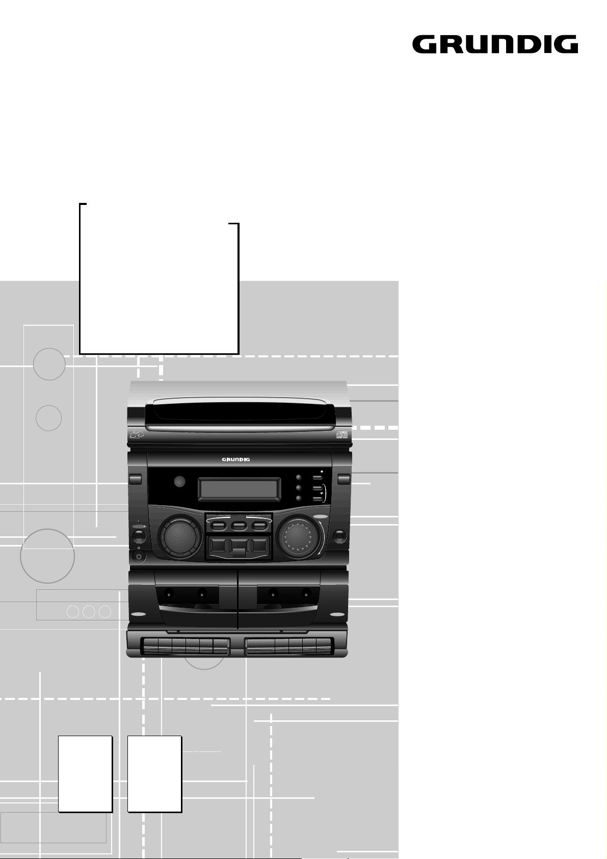
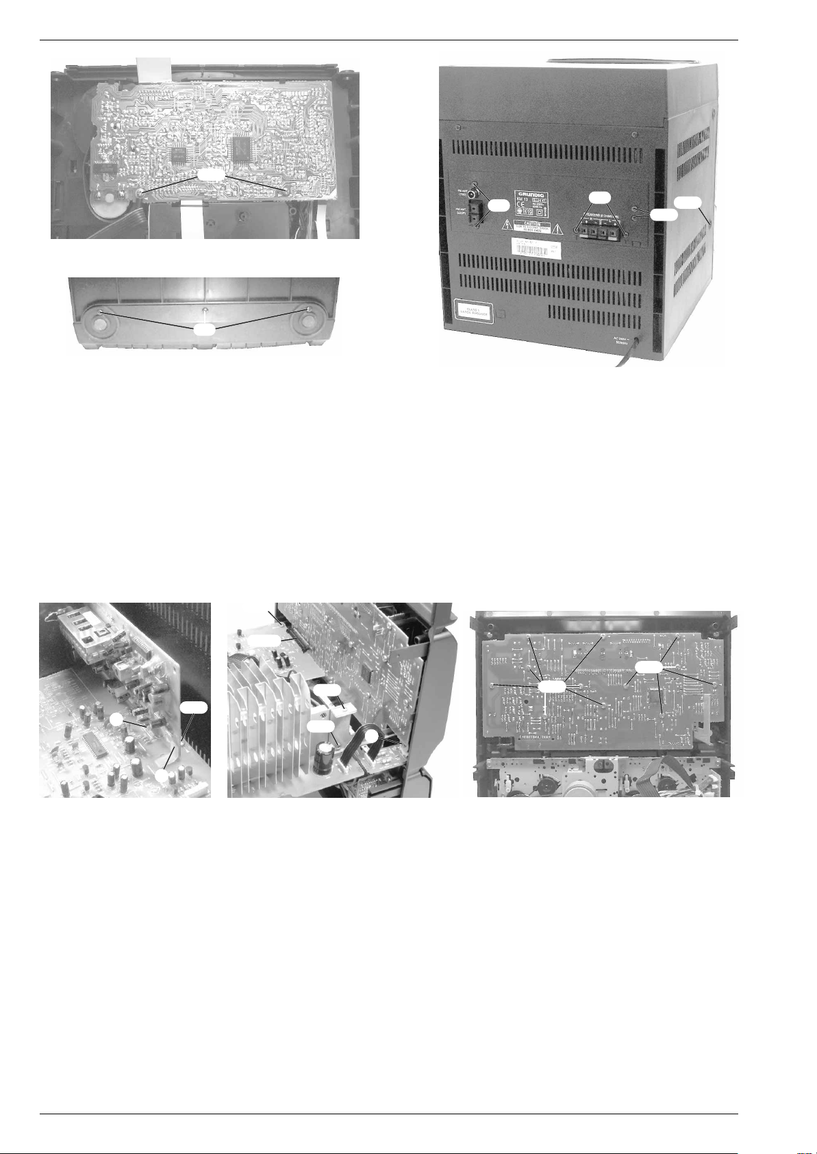
1. Gehäuseoberteil M32
- CD-Schublade M1
Schubladenblende M10
- 2 Schrauben M80
2
herausziehen, 2 Rastnasen A ausrasten und
1
und 2 Schrauben M781 herausschrauben
(Fig. 2).
- Gehäuseoberteil M32
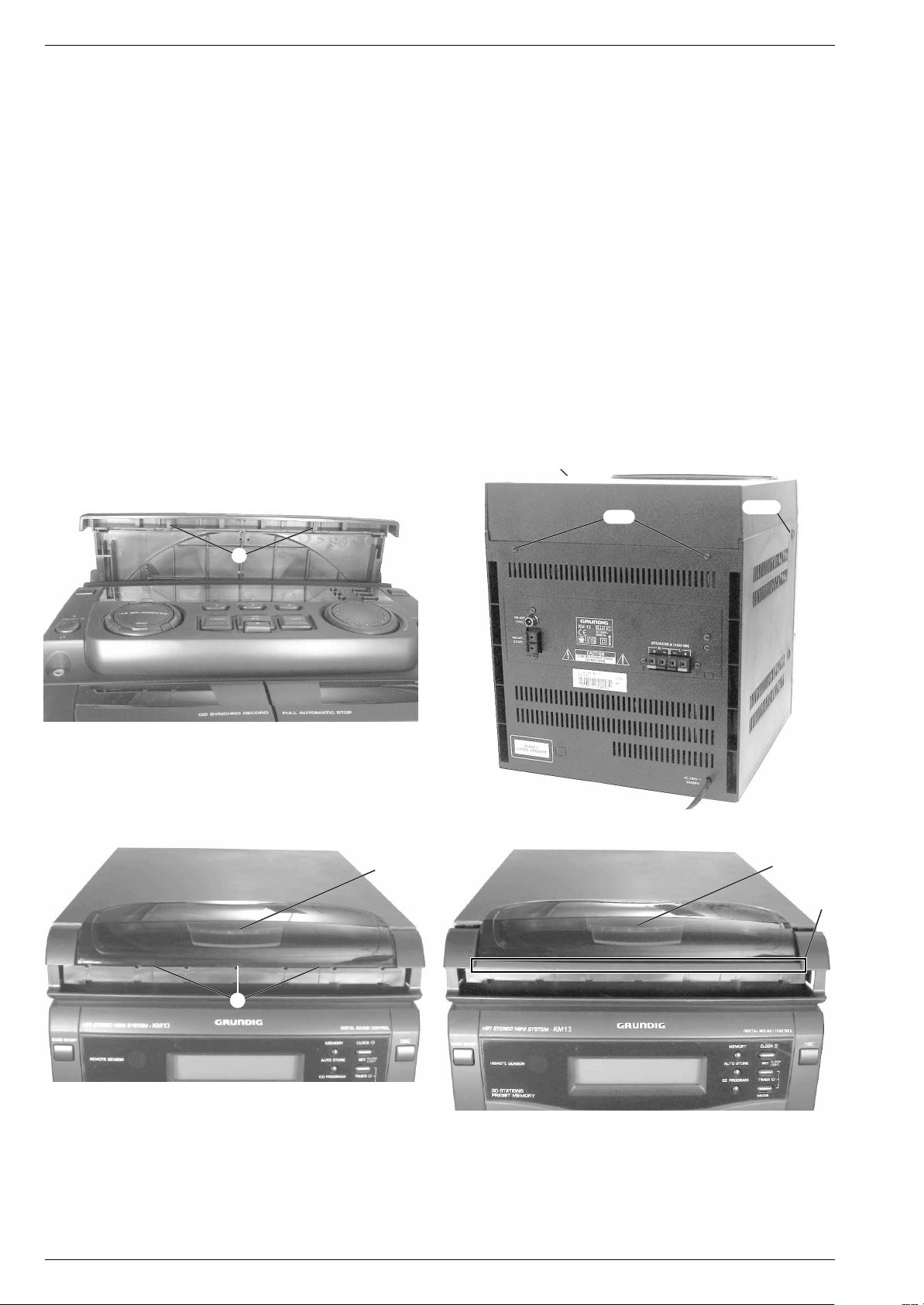
- Die 3 kleinen Rastnasen B an der Fensterunterkante ausrasten
(Fig. 3), das Fenster M33
nach oben drücken bis man das Fenster M33
Frontblende M8
1
nach hinten schieben kann (Fig. 4).
- Gehäuseoberteil M32
bei Bedarf die beiden Steckverbindungen lösen.
Achtung:
M33
Das Gehäuseoberteil M321 kann nur ohne das Fenster
1
eingebaut werden. Das Fenster M331 muß zuvor ausgebaut
werden, wie unter Pkt. 2. beschrieben.
1
) kann man erkennen, in welcher
1
mit CD-Teil ausbauen
1
nach oben abnehmen (Fig. 1).
1
mit CD-Teil hinten 2-3cm anheben.
1
mit dem Gehäuseoberteil M321 soweit
1
mit dem CD-Teil nach oben abnehmen und
1
über den Steg X der
Disassembly Instructions
The designations of parts (e.g. M71) in the text and figures are identical
with the position numbers in the spare parts lists and exploded views.
From the index number (…1) it can be seen in which exploded view this
part is to be found.
The exploded views are shown in chapter „Spare Parts Lists and
Exploded Views“.
1. Removing the Cabinet Top M32
- Draw out the CD tray M1
tray cover M10
1
towards the top (Fig. 1).
- Undo 2 screws M80
- Lift the cabinet top M32
2
1
and 2 screws M781 (Fig. 2).
1
with the CD unit on the rear side by 2-3cm.
- Disengage the 3 small catches B at the bottom edge of the window
(Fig. 3), press the window M33
until it is possible to move the window M33
cover M8
- Lift the cabinet top M32
1
to the rear (Fig. 4).
1
with the CD unit to remove it. If necessary
loosen the connectors.
Attention:
window M33
The cabinet top M321 can only be fitted without the
1
. For this, remove the window M331 first as described
under para 2.
1
M78
M80
1
with CD Unit
, disengage 2 catches A and pull out the
1
with the cabinet top M321 upwards
1
1
over rail X of the front
1
M78
Fig. 1
A
B
M33
Fig. 2
1
1
M33
X
Fig. 3
Fig. 4
1
2. Fenster M33
- Gehäuseoberteil M32
ausbauen
1
mit CD-Teil ausbauen (Pkt.1).
- Die 4 Rastnasen C ausrasten und das Fenster M33
(Fig. 5, 6).
- Das Fenster M33
1
darf nur bei eingebautem Gehäuseoberteil M32
1
abnehmen
2. Removing Window M33
- Remove cabinet top M321 with CD unit (para 1).
- Disengage 4 catches C and take out window M33
1
- The window M33
cabinet top M32
1
1
1
1
(Fig. 5, 6).
is allowed to be inserted onlyafter having fitted the
.
eingesetzt werden.
1 - 4 GRUNDIG Service
Page 5
M33
1
Fig. 5
C
Fig. 6
C
M33
Allgemeiner Teil / General SectionKM 13
1
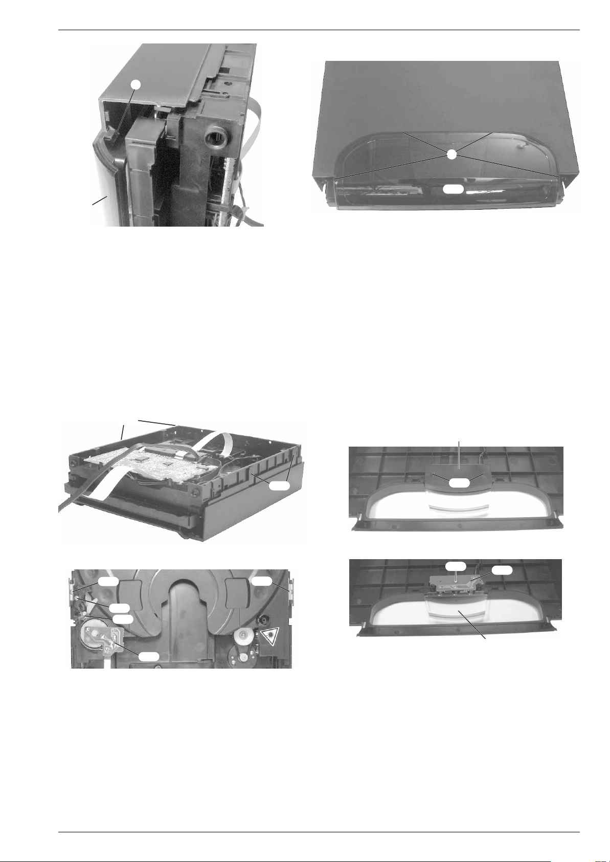
3. CD-Teil ausbauen
- Gehäuseoberteil M32
- 4 Schrauben M26
- Bei Bedarf die Leitung für die CD-Beleuchtungsplatte M29
1
mit CD-Teil ausbauen (Pkt. 1).
1
herausschrauben (Fig. 7).
1
lösen
und das CD-Teil aus dem Gehäuseoberteil herausnehmen.
1
4. CD-Beleuchtungsplatte M29
- CD-Teil ausbauen (Pkt. 3).
- 2 Schrauben M26
abnehmen (Fig. 8).
- Schraube M28
1
herausschrauben und die Abdeckung M27
1
der CD-Beleuchtungsplatte M291 herausschrauben
ausbauen
(Fig. 9).
- Die Leiterplatte M291 und der Lichtleiter M301 können aus dem
Gehäuseoberteil M32
1
herausgenommen werden (Fig. 9).
1
M26
M26
1
Fig. 7
M42
2
M42
2
3. Removing the CD Unit
- Remove cabinet top M321 with the CD unit (para 1).
- Undo 4 screws M26
- If necessary disconnect the lead for the CD-LED circuit board M29
1
(Fig. 7).
1
and take the CD unit out of the cabinet top.
4. Removing the CD-LED Circuit Board M29
1
- Remove the CD unit (para 3).
- Undo 2 screws M26
- Undo screw M28
- Circuit board M29
from the cabinet top M32
1
and take cover M271 off (Fig. 8).
1
on the CD-LED circuit board M291 (Fig. 9).
1
and fiber-optic light guide M301 can be taken out
1
(Fig. 9).
M27
M26
1
1
1
Fig. 8
1
M28
M29
1
2
M33
2
M30
1
M30
M34
2
Fig. 9
Fig. 10
5. CD-Teil zerlegen
- CD-Teil ausbauen (Pkt.3).
5.1 CD-Schublade ausbauen
- Bei Bedarf die Flachbandleitung zur Drehtellermotorplatte M34
lösen (Fig. 10).
- 2 Schrauben M42
denführungen M41
2
(Fig. 10) herausschrauben und die Schubla-
2
abnehmen.
2
5. Dismantling the CD Unit
- Remove the CD unit (para 3).
5.1 Removing the CD Tray
- If necessary disconnect the ribbon cable to the disc turntable motor
2
M34
(Fig. 10).
- Undo 2 screws M42
2
(Fig. 10) and take the tray guides M412 off.
- Pull the tray out.
- Die Schublade herausziehen.
GRUNDIG Service 1 - 5
Page 6

Allgemeiner Teil / General Section KM 13
5.2 Move/Stop-Platte M282 ausbauen
- Schraube M33
2
M32
abnehmen.
- Die Feder M30
Leiterplatte M28
2
(Fig. 10) herausschrauben und die Abdeckung
2
(Fig. 10) aushängen, den Hebel M272 und die
2
herausnehmen.
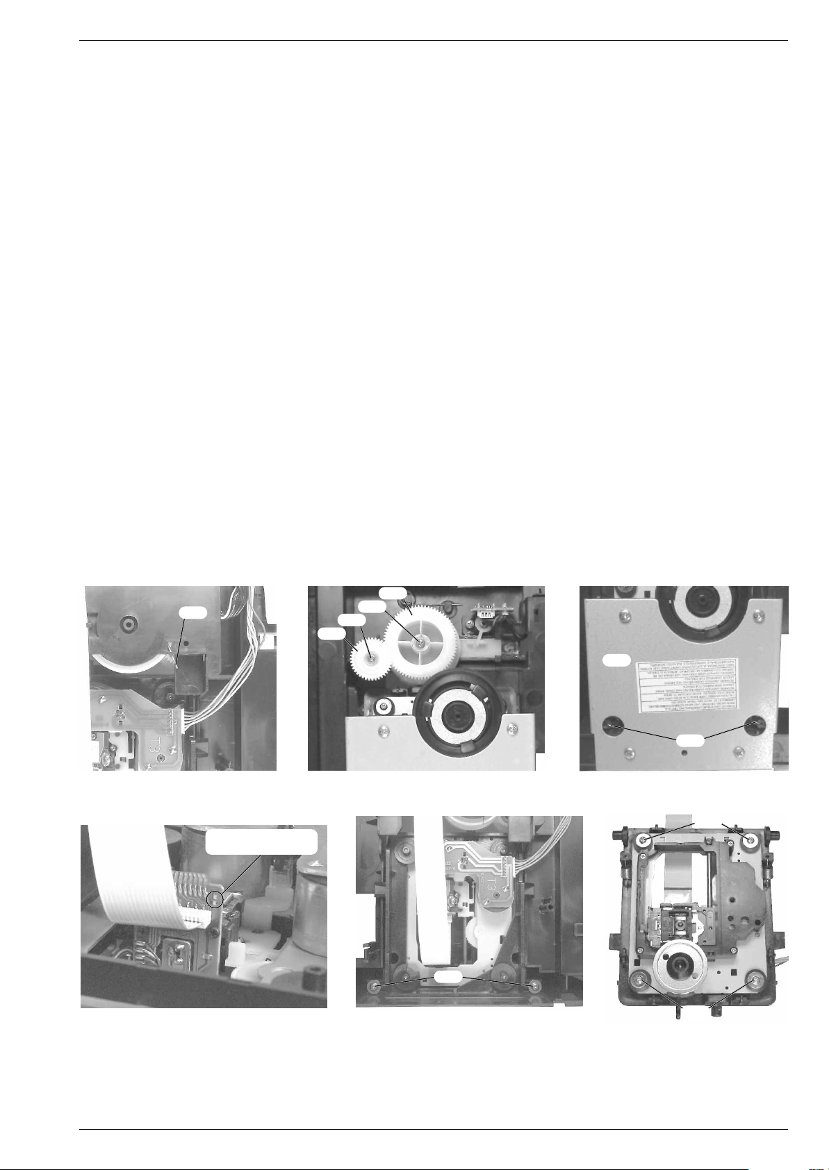
5.3 CD-Tellermechanik ausbauen
- CD-Schublade ausbauen (Pkt. 5.1).
- Schraube M25
abnehmen.
- Die aufgeklebte Zahnradabdeckung M21
fernen.
- Das kleine Zahnrad M18
einfach nach oben herausgenommen werden.
- Das sperrbare Zahnrad M17
wenn der Verriegelungshebel M8
wird.
- Schraube M9
der Verriegelunshebel M8
2
(Fig. 11) herausschrauben und den Teller M24
2
(Fig. 12) vorsichtig ent-
2
und das Doppelzahnrad M202 kann
2
kann nur herausgenommen werden
2
(Fig. 13) zurückgeschoben
2
(Fig. 14) herausschrauben, das Zahnrad M102 und
2
(Fig. 13, 14) können herausgenom-
men werden.
- Die Sicherungscheibe M32 (Fig. 14) lösen und beim Herausnehmen des Zahnrads M6
achten, diese kann wegspringen.
- Die Riemenscheibe M13
Herausschrauben der jeweilgen Schraube M12
genommen werden.
- 2 Schrauben M16
motor E1
5.4 Disc Counter-Platte M23
- Schraube M25
2
herausnehmen.
2
2
auf die darunterbefindliche Feder M5
2
und das Zahnrad M152 können durch
2
(Fig. 14) herausschrauben und Drehteller-
2
ausbauen
2
(Fig. 14) heraus-
(Fig. 11) herausschrauben und den Teller M24
abnehmen.
- Die Klebestellen am Schalter lösen, die Rastnase D (Fig. 13)
ausrasten und Leiterplatte M23
2
herausnehmen.
5.2 Removing the Move/Stop Circuit Board M28
- Undo screw M332 (Fig. 10) and take the cover M322 off.
- Detach spring M30
2
M28
.
2
(Fig. 10), remove lever M272 and circuit board
2
5.3 Removing the CD Turntable Mechanics
2
2
2
- Remove the CD tray (para 5.1).
- Undo screw M25
- Remove the glued on gearwheel cover M21
- The small gearwheel M18
lifted and removed.
- The lockable gearwheel M17
pushed back the locking lever M8
- Undo screw M9
(Fig. 13, 14) can be taken out.
- Loosen the securing washer M3
gearwheel M6
- Pulley M13
corresponding screw M12
- Undo 2 screws M16
5.4 Removing the Disc Counter Circuit Board M23
2
(Fig. 11) and take turntable M242 out.
2
and the gear pair M202 can simply be
2
can only be taken out after having
2
2
(Fig. 14), gearwheel M102 and locking lever M8
2
take care of spring M52 below it. It may come off.
2
and gearwheel M152 can be taken out by undoing the
2
2
(Fig. 14) and remove the turntable motor E12.
(Fig. 13).
2
(Fig. 14). When taking out the
(Fig. 14).
2
(Fig. 12) carefully.
2
- Undo screw M252 (Fig. 11) and take the turntable M242 off.
- Loosen the glued joints on the switch, disengage catch D (Fig. 13)
and remove circuit board M23
2
.
2
2
M21
2
M25
Fig. 11 Fig. 12 Fig. 13
2
Fig. 14
M3
M9
M12
2
M16
M8
2
2
2
Fig. 15
M42
M61
2
M46
2
2
M8
2
D
2
M42
2
M57
2
M16
5.5 CD Deck Up/Down-Platte M61
- CD-Schublade ausbauen (Pkt. 5.1).
- Schraube M42
zur CD-Decoder-Platte M35
Platte M61
2
(Fig. 15) herausschrauben, bei Bedarf die Leitung
2
(Fig. 15) herausnehmen.
2
lösen und die CD Deck Up/Down-
2
ausbauen
5.5 Removing the CD Deck Up/Down Circuit Board M61
- Remove the CD tray (para 5.1).
- Undo screw M42
circuit board M35
Down circuit board M61
2
(Fig. 15), disconnect the lead to the CD decoder
2
if necessary, and remove the CD Deck Up/
2
(Fig. 15).
2
1 - 6 GRUNDIG Service
Page 7
Allgemeiner Teil / General SectionKM 13
5.6 CD Deck Open/Close-Platte M572 ausbauen
- CD-Schublade ausbauen (Pkt. 5.1).
- Schraube M42
2
herausschrauben und die Leiterplatte M572 her-
ausnehmen (Fig. 15).
5.7 CD-Schubladenantrieb ausbauen
- CD-Schublade ausbauen (Pkt. 5.1).
- Die Riemenscheibe M52
Herausschrauben der jeweilgen Schraube M46
2
und das Zahnrad M562 kann durch
2
(Fig. 15) heraus-
genommen werden.
- CD-Decoder-Platte ausbauen (Pkt. 5.10).
- 2 Schrauben M16
motor E1
2
5.8 CD-Laufwerklift ausbauen
- Die Feder M59
abgebildet.
- Die Schrauben M29
2
(Fig. 15) herausschrauben und Schubladen-
nach unten herausnehmen.
2
in die Service-Stellung bringen wie in Fig. 16
2
, M462 herausschrauben, das Zahnrad M62
und das Kurvenrad M642 abnehmen (Fig. 17).
5.9 CD-Laufwerk ausbauen
*Achtung:
Bei Ausbau des CD-Laufwerks muß vor Abziehen der
Steckverbindungen eine Schutzlötstelle auf der Leiterplatte
(Fig. 19) der Lasereinheit angebracht werden, um eine Zerstörung
der Laserdiode durch statische Aufladung zu vermeiden.
Beim Einbau einer neuen Lasereinheit muß nach Einstecken der
Steckverbindungen die werkseitig angebrachte Schutzlötstelle
entfernt werden.
- Das CD-Laufwerk in die oberste Liftstellung bringen.
- Die beiden Federn M47
Das Ausbauen der Metallplatte M65
der Federn M47
- Bei Bedarf die Verbindungsleitungen lösen*.
- Die beiden Schrauben M46
2
(Fig. 18) aushängen.
2
(Fig. 18).
2
erleichtert das Einhängen
2
(Fig. 20) auf der Unterseite herausschrauben und das CD-Laufwerk mit dem Laufwerkrahmen von
unten herausnehmen.
- 4 Schrauben M50
2
(Fig. 21) herausschrauben und das CD-Lauf-
werk aus dem Laufwerkrahmen herausnehmen.
5.6 Removing the CD Deck Open/Close Circuit Board M57
- Remove the CD tray (para 5.1).
- Undo screw M42
2
and remove circuit board M572 (Fig. 15).
2
5.7 Removing the CD Tray Gear
- Remove the CD tray (para 5.1).
- Pulley M52
corresponding screw M46
- Remove the CD-Decoder circuit board (para 5.10).
- Undo 2 screws M16
2
and gearwheel M562 can be taken out by undoing the
2
(Fig. 15).
2
(Fig. 15) and remove the tray motor E1
2
towards the bottom.
5.8 Removing the Lift of the CD Drive Mechanism
- Set spring M59
2
- Undo screws M29
(Fig. 17).
2
in service position as shown in Fig. 16.
2
, M462 , take out gearwheel M622 and cam M64
2
5.9 Removing the CD Drive Mechanism
*Warning:
Before detaching the plug-in connections when
removing the CD drive mechanism a protective solder joint must be
provided on the circuit board (Fig. 19) of the laser pick-up to avoid
the laser diode being destroyed by static charges.
When fitting a new laser pick-up the protective solder joint provided
in the factory must be removed before inserting the plug-in
connections.
- Move the CD drive mechanism to its upper limit lift position.
- Detach the two springs M47
The springs M47
plate M65
2
can be attached easier when removing the metal
2
(Fig. 18).
- Loosen the conncting leads if necessary*.
- Undo the two screws M46
CD drive mechanism together with the frame from the bottom.
- Undo the 4 screws M50
2
(Fig. 18).
2
(Fig. 20) on the bottom and remove the
2
(Fig. 21) and remove the CD drive
mechanism from its frame.
Fig. 16
2
M59
Schutzlötstelle
protective soldered joint
M62
Fig. 17
M29
2
M46
2
M64
2
2
2
M65
2
M47
Fig. 18
2
M50
2
M46
2
Fig. 19
5.10 CD-Decoder-Platte M352 ausbauen
- 2 Schrauben M36
motorkontakte E1
- Die Leiterplatte M35
2
herausschrauben (Fig. 22), die Schubladen-
2
ablöten.
2
herausnehmen und bei Bedarf die Steck-
verbindungen lösen.
Fig. 20
Fig. 21
5.10 Removing the CD-Decoder Circuit Board M35
- Undo 2 screws M362 (Fig. 22), unsolder the tray motor contacts
2
E1
.
- Remove the circuit board M35
connections if necessary.
M50
2
2
and detach the plug-in
GRUNDIG Service 1 - 7
Page 8
Allgemeiner Teil / General Section KM 13
2
M36
1
M7
1
M7
M79
1
M71
1
Fig. 22
1
M7
Fig. 23
6. Hauptplatte M601 ausbauen
- Gehäuseoberteil M32
- Bei Bedarf die Steckverbindungen lösen.
- 4 Schrauben M7
1
M7
(Fig. 23) auf der Geräteunterseite herausschrauben.
- 2 Schrauben M79
(Fig. 24).
- Schraube M15
mit der kompletten Gerätefront nach vorne herausziehen.
- Schraube M15
1
mit CD-Teil ausbauen (Pkt. 1).
1
(Fig. 24) auf der Geräterückseite und 3 Schrauben
1
und 2 Schrauben M711 herausschrauben
1
(Fig. 25) herausschrauben und Hauptplatte M60
1
, 2 Schrauben M591 und Schraube G herausschrau-
ben (Fig. 26).
- Die über die Steckverbindung CN301 (Fig. 26) mit der Frontplatte
1
M37
verbundene Hauptplatte M601 abziehen.
1
M15
CN301
1
M59
1
KF
M15
M59
1
1
KG
Fig. 24
6. Removing the Main Circuit Board M60
1
- Remove the cabinet top M321 with CD unit (para 1).
- Detach the plug-in connections if necessary.
- Undo the 4 screws M7
(Fig. 23) on the bottom of the mini system.
- Undo 2 screws M79
- Undo screw M15
together with the complete front of the mini system towards the front.
- Undo screw M15
- Pull off the main circuit board M60
circuit board M37
1
(Fig. 24) on the rear and 3 screws M7
1
and 2 screws M711 (Fig. 24).
1
(Fig. 25) and pull out the main circuit board M60
1
, 2 screws M591 and screw G (Fig. 26).
1
by CN301(Fig. 26).
M15
1
which is plugged into the front
1
M15
1
1
1
KE
Fig. 25 Fig. 26
1
7. Frontplatte M37
- Hauptplatte M60
- Lautstärkeknopf von vorne abziehen.
- 12 Schrauben M15
1
M37
abnehmen.
8. Cassettentürbremse M9
- Gehäuseoberteil M32
- Bei Bedarf die Seckverbindungen lösen.
- 4 Schrauben M7
1
M7
(Fig. 23) auf der Geräteunterseite herausschrauben.
- 2 Schrauben M79
(Fig. 24).
- Schraube M15
mit der kompletten Gerätefront nach vorne herausziehen.
- Die Rastnase H (Fig. 28) ausrasten und die Cassettentürbremse
ausbauen
1
ausbauen (Pkt. 6).
1
(Fig. 27) herausschrauben und die Frontplatte
1
ausbauen
1
mit CD-Teil ausbauen (Pkt. 1).
1
(Fig. 24) auf der Geräterückseite und 3 Schrauben
1
und 2 Schrauben M711 herausschrauben
1
(Fig. 25) herausschrauben und Hauptplatte M60
7. Removing the Front Circuit Board M37
- Remove the main circuit board M601 (para 6).
- Pull off the volume control knob from the front.
- Undo 12 screws M15
M37
8. Removing the Brake of the Cassette Door M9
- Remove the cabinet top M321 with the CD unit (para 1).
- Detach the plug-in connections if necessary.
- Undo the 4 screws M7
(Fig. 23) on the bottom of the mini system.
- Undo 2 screws M79
1
- Undo screw M15
together with the complete front of the mini system towards the front.
- Disengage catch H (Fig. 28) and remove brake M9
door.
M91 herausnehmen.
1 - 8 GRUNDIG Service
Fig. 27
1
1
1
.
(Fig. 27) and remove the front circuit board
1
1
(Fig. 24) on the rear and 3 screws M7
1
and 2 screws M711 (Fig. 24).
1
(Fig. 25) and pull out the main circuit board M60
1
of the cassette
1
1
Page 9
H
Allgemeiner Teil / General SectionKM 13
1
M15
Fig. 28
9. Tuner ausbauen
- 2 Schrauben M7
1
(Fig. 24) herausschrauben.
Fig. 29
- Rastung E (Fig. 25) ausrasten und Tuner abziehen.
- Beim Wiedereinbau auf korrekten Sitz des Steckverbinders F
(Fig. 25) achten.
10. Kopfhörerplatte ausbauen
- Schraube G (Fig. 26) herausschrauben.
11. Laufwerk ausbauen
- Hauptplatte M60
- Die beiden Cassettentüren öffnen.
- 6 Schrauben M15
1
ausbauen (Pkt. 6).
1
(Fig. 29) herausschrauben und das Laufwerk
abnehmen.
M15
1
M15
1
J
9. Removing the Tuner
- Undo 2 screws M7
- Unhook the catch E (Fig. 25). and pull off the tuner.
- When reassembling take care of the correct position of connector F
(Fig. 25).
10. Removing the Headphone Board
- Undo screw G (Fig. 26).
11. Removing the Drive Mechanism
- Remove the main circuit board M60
- Open the two cassette doors.
- Undo 6 screws M15
1
(Fig. 24).
1
(para 6).
1
(Fig. 29) and take the drive mechanism off.
L
L
N
K
M
K
Fig. 30
Fig. 31
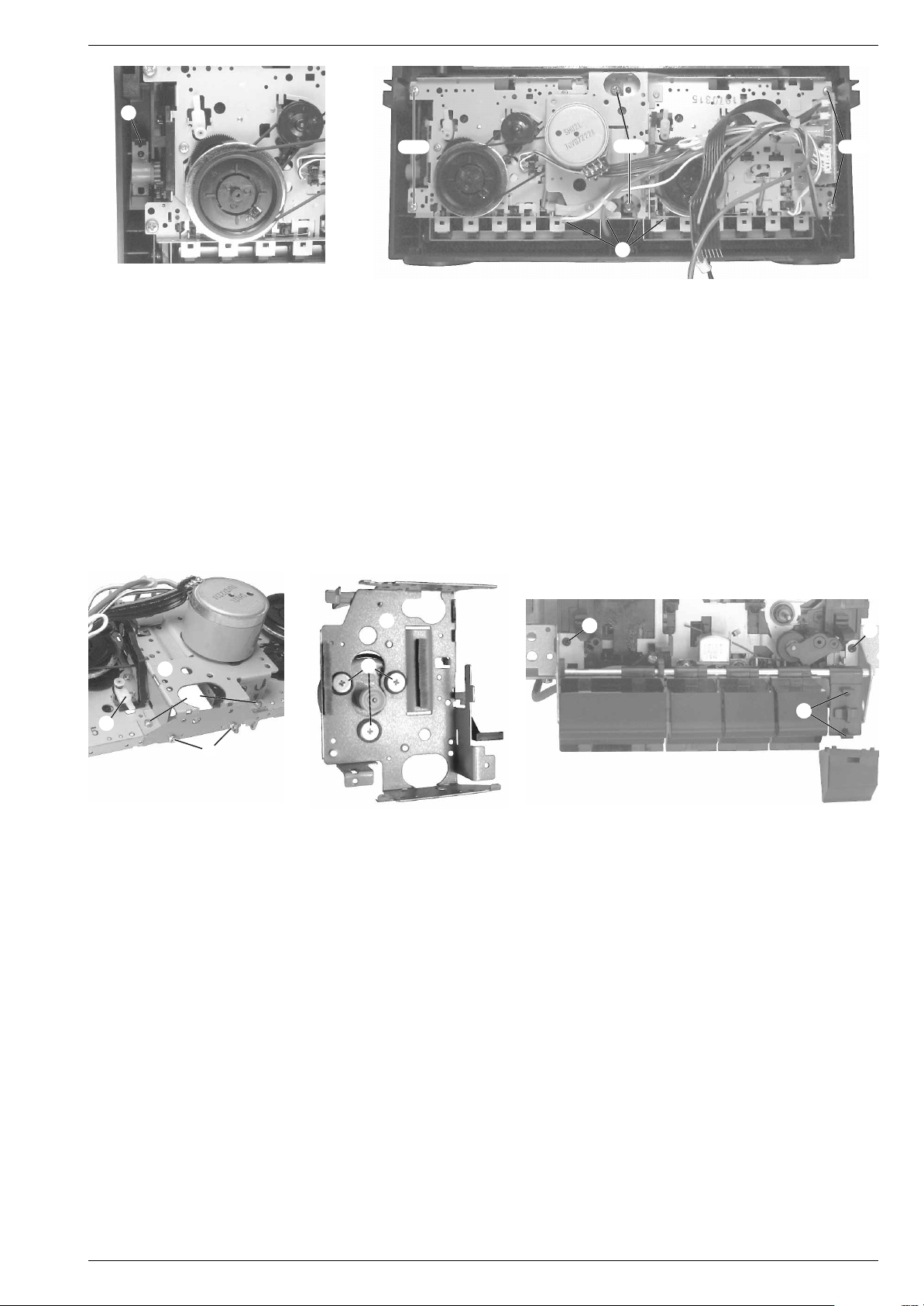
12. Laufwerk zerlegen
- Laufwerk ausbauen (Pkt. 11).
12.1 Motor ausbauen
- Flachbandleitung zum Motor ablöten.
- Die beiden Antriebsriemen aushängen.
- Die 4 Schrauben J (Fig. 29), die 4 Schrauben K (Fig. 30)
herausschrauben und den Verbindungsrahmen L vorsichtig
aushängen.
Achtung:
auf den Pausenverriegelungshebel M achten (Fig. 30)!
- 3 Schrauben N herausschrauben und den Motor abnehmen
(Fig. 31).
12.2 Laufwerktasten M41
- Jeweils die beiden Rastnasen O (Fig. 32) auf den Tastenträgern
ausrasten und die auszuwechselnden Tasten abnehmen.
12.3 Laufwerktastenrahmen ausbauen
- Laufwerktasten M41
- Die 2 Schrauben P (Fig. 32) des auszubauenden Rahmens
herausschrauben.
- Den Tastenrahmen aushängen, indem man den Rahmen auf der
linken Seite nach unten schiebt und leicht anhebt, danach den
Rahmen vorsichtig nach rechts schieben, bis der Laufwerktastenrahmen abgenommen werden kann.
Beim Aus- und Einbau des Verbindungsrahmens L
1
- M511 ausbauen
1
- M511 ausbauen (Pkt. 12.2).
KPP
KO
Fig. 32
12. Disassembling the Drive Mechanism
- Dismantle the drive mechanism (para 11).
12.1 Removing the Motor
- Unsolder the ribbon cable to the motor.
- Detach the two drive belts.
- Undo 4 screws J (Fig. 29), 4 screws K (Fig. 30) and disengage
the connecting frame L carefully.
Warning:
take care of the pause locking lever M (Fig. 30)!
- Undo 3 screws N and take the motor off (Fig. 31).
12.2 Removing the Tape Deck Operating Buttons M41
- Disengage the two catches O (Fig. 32) on each of the button
carriers and remove the buttons which are to be replaced.
12.3 Removing the Frame of the Tape Deck Operating Buttons
- Remove the tape deck operating buttons M41
(para 12.2).
- Undo the 2 screws P (Fig. 32) of the frame which is to be
removed.
- Push the frame of the buttons down on the left side and raise it
slightly to detach it, then push it carefully to the right until it can be
taken off.
When removing and refitting the connecting frame L
1
- M51
1
- M51
1
1
GRUNDIG Service 1 - 9
Page 10
Allgemeiner Teil / General Section KM 13
1 - 10 GRUNDIG Service
Bedienhinweise Dieses Kapitel enthält Auszüge aus der Bedienungsanleitung. Weitergehende Informationen entnehmen Sie bitte der gerätespezifischen Bedienungsanleitung, deren
Sachnummer Sie in der entsprechenden Ersatzteilliste finden.
POWER
CD
1
2
3
M.SCAN
RANDOM
REPEA
T
TIME
SKIP
PROGRAM
CLEAR
CHECK
PRESET
TUNER/BAND
TAPE
B.BOOST
FM MODE
SLEEP
MUTE
VOLUME
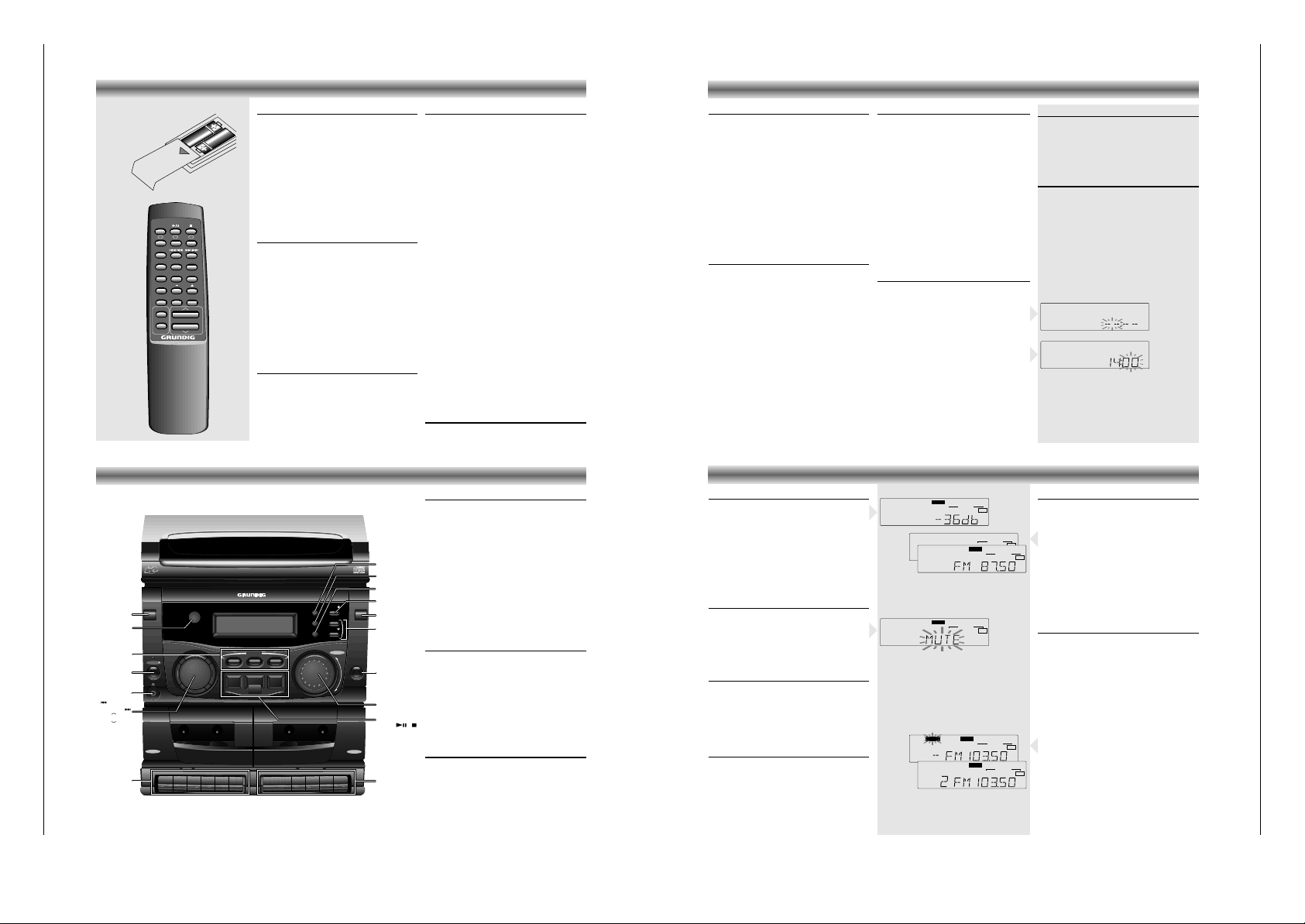
Batteriewechsel
Läßt die Reichweite Ihres IR-Gebers nach oder
lassen sich einzelne Funktionen nicht mehr
ausführen, sollten Sie die Batterien auswechseln.
• Verwendeter Batterietyp 2x Micro 1,5 Volt LR03,
Größe AAA.
• Öffnen Sie zum Batteriewechsel den Deckel des
Batteriefaches auf der Rückseite des Gebers.
Achten Sie auf die richtige Polung der Batterien
(Markierung im Batteriefach beachten).
Umwelthinweis:
Denken Sie beim Batteriewechsel daran: Batterien
sind Sondermüll.
Allgemeine Tasten
ON/OFF y - zum Ein-und Ausschalten des Geräts.
MUTE - zum Stummschalten der Lautsprecher.
Nochmaliges Drücken stellt den Klang wieder her.
VOLUME C/D - Drücken Sie Taste D, um die
Lautstärke zu reduzieren, bzw. die Taste C, um sie
zu erhöhen. Jedes Mal, wenn das Gerät angestellt
wird, stellt sich die Lautstärke auf den vorherigen
Pegel ein.
B.BOOST -
Zum Ein- /Ausschalten der dynamischen
Baßverstärkung
SLEEP - Einstellen einer Zeit, zu der sich das Gerät
automatisch abschaltet.
Radiofunktionen
TUNER/BAND -
Einstellen der Radiofunktion und
Einstellen des Wellenbereichs AM oder FM.
FM MODE - Auswahl des FM-Stereo oder -Mono-
Empfangs.
PRESET 34- Auswahl innerhalb der 30 UKW-
oder AM-Senderspeicher.
CD-Funktionen
CD 2/; - Einstellen der CD-Funktion und zum
Starten der Wiedergabe, zum temporären
Unterbrechen und anschließendem Fortfahren der
Wiedergabe.
STOP 9 - Beenden der CD Wiedergabe oder
Löschen eines Programmes
DISC SELECT
123
- Auswahl einer CD, die
wiedergegeben werden soll.
M.SCAN - spielt die ersten 10 Sekunden jedes
Stücks jeder CD an.
SKIP S/Q - Einmal drücken, springt an den
Anfang des vorherigen Stücks. Durch mehrmaliges
Drücken gelangen Sie an die Anfänge aller
vorheriger Stücke. Halten Sie diese Taste während
Wiedergabe gedrückt, um die CD in
Rückwärtsrichtung zu durchlaufen.
SKIP R/T - Springen Sie durch einmaliges
Drücken an den Anfang des folgenden Stücks. Halten Sie diese Taste während Wiedergabe gedrückt,
um die CD in Vorwärtsrichtung zu durchlaufen.
RANDOM - Wiedergabe in willkürlicher Reihenfolge.
REPEAT - zur Wiederholung eines Stücks, einer
oder aller drei CDs.
TIME - Umschalten der im Display angezeigten
Information zwischen verstrichener Wiedergabezeit,
verbleibende Zeit des aktuellen Stücks oder
verbleibende Zeit der gesamten CD.
PROGRAM - Programmierung von bestimmten
Musikstücken.
CLEAR - Löschen eines programmierten Titels.
CHECK - Anzeige eines Programminhaltes.
Cassettenfunktionen
TAPE - Einstellen der TAPE-Funktion.
FERNBEDIENUNG
BEDIENELEMENTE AN DER VORDERSEITE
Bedienelemente Verstärker
ON/OFF y – Gerät einschalten oder in Bereit-
schaftsfunktion bringen (6 erscheint, solange das
Gerät mit dem Netz verbunden ist).
REMOTE SENSOR – Empfang der Signale der
Fernbedienung.
BASS BOOST – Zum Ein- und Ausschalten der
Baßverstärkung
DSC – Digital Sound Control - Zum Wählen der gewünschten Klangeffekte: JAZZ, POP, ROCK oder FLAT.
VOLUME – Mit diesem Regler passen Sie die
Lautstärke an.
CD B;/TAPE/TUNER – Gerät einschalten und
Wählen der Signalquelle. Wird CD B; gedrückt,
beginnt bei eingelegter CD sofort die Wiedergabe.
p – Kopfhöreranschluß
Bedienelemente Radio
TUNER – Radio einschalten und Wellenbereich AM
oder FM einstellen
.
PRESET CD – Wählen eines gespeicherten
Radiosenders.
SKIP/SEARCH ST–
Drücken Sie die Taste
T
, um höhere
bzw. S, um niedrigere
Frequenzen auszuwählen.
MEMORY – Speichern von Radiosendern.
AUTO STORE – Automatische Speicherung von bis
zu 30 Sendern.
Uhren-/Timer-Regler
S SKIP/SEARCH T – Einstellen der Stunden
und Minuten für Uhr und Timer.
CLOCK – Einstellen oder Anzeigen der Uhr.
TIMER SET/CLOCK LIGHT – Einstellen oder
Anzeigen der On/Off-Zeit und Beleuchten des
Displays zum Überprüfen der Uhr, wenn das Gerät
nicht mit Strom gespeist wird.
TIMER MODE – Timer einschalten.
S SKIP/SEARCH T
C
D
TUNER
TAPE
CD
aB;
9
0 RECORD
Q
R
9//
;
Q
R
9//
;
B
B
3
1
2
DECK A
DECK B
BASS
BOOST
PHONES
PRESET
DSC
ON/OFF y
REMOTE
SENSOR
VOLUME
SKIP/
SEARCH
/
OPEN/CLOSE
CLOCK
MEMORY
DISC
SELECT
TUNER
CD
TAPE
TIMER
CD PROGRAM
AUTO STORE
PRESET
PRESET
BASS BOOST
REMOTE SENSOR
12
3
MEMORY
AUTO STORE
CD PROGRAM
MODE
SET
DSC
a/
OPEN/CLOSE
DIGITAL SOUND CONTROL
3 - DISC CD CHANGER
HIFI STEREO MINI SYSTEM
KM13
CD SYNCHRO RECORD
DECK A
FULL AUTOMATIC STOP
TIMER
CLOCK
VOLUME
ON/OFF
DECK B
RECORD/PLAYBACK
PLAYBACK
30 STATIONS
PRESET MEMORY
DISC SELECT
BEDIENELEMENTE BEDIENUNG
p (Kopfhörer)-Öffnung
Der Kopfhörerstecker bietet privates Hörvergnügen.
Möchten Sie Kopfhörer verwenden, setzen Sie die
Lautstärke auf das Minimum und führen Sie einen
3.5 mm Ministecker der Kopfhörer in die pÖffnung. Die Lautsprecher werden abgeschaltet,
sobald der Anschluß des Steckers erfolgt ist.
Displaybeleuchtung
• Bei abgeschaltetem Strom CLOCK LIGHT
drücken.
– Die Hintergrundbeleuchtung des Displays wird
fünf Sekunden lang eingeschaltet.
Bedienelemente CD
CD B; – CD-Spieler einschalten und Beginnen
oder Unterbrechen einer CD Wiedergabe.
9 –
Beenden der CD Wiedergabe oder Löschen
eines Programmes
S SKIP/SEARCH T – Kurz drücken:
Titelsprung vor- oder rückwärts.
Halten Sie diese Taste während Wiedergabe
gedrückt, um die ausgewählte CD in Vorwärtsoder Rückwärtsrichtung zu durchlaufen.
CD PROGRAM – Programmieren von Titeln.
OPEN/CLOSE / – Öffnen oder Schließen des CD
Faches
DISC SELECT 1~3 – bewegt den drehbaren CD-
Teller, um eine CD auswählen zu können.
Bedienelemente Cassettendeck
TAPE 1 – Bedienelemente an Deck A
0 RECORD
– Starten der Aufnahme.
B – Starten der Wiedergabe.
5 – Schneller Rücklauf.
6 – Schneller Vorlauf.
9// – Stoppen des Bandlaufs und
Öffnen des Cassettenfachs.
; – Unterbrechen der Wiedergabe
TAPE 2 – Bedienelemente an Deck B
B – Starten der Wiedergabe.
5 – Schneller Rücklauf.
6 – Schneller Vorlauf.
9// – Stoppen des Bandlaufs und
Öffnen des Cassettenfachs.
; – Unterbrechen der Wiedergabe
An- und Ausschalten des Geräts
• Drücken Sie die Taste ON/OFF y am Gerät
oder an der Fernbedienung, um die Anlage
einzuschalten.
• Drücken Sie nochmals ON/OFF y, um die
Anlage auszuschalten.
• Ist das Gerät durch eine dieser Weisen ausgeschaltet, leuchtet die Standby-Anzeige 6.
Hinweis: Selbst wenn Sie die Anlage
ausschalten, bleibt die Stromversorgung über das
Netz erhalten.
Um die Stromversorgung zur Anlage vollständig
zu unterbrechen, den Netzstecker ziehen.
Automatische Stromeinschaltung
• Durch Drücken von TUNER, CD B; oder TAPE
auf dem Hauptgerät wird das Gerät automatisch eingeschaltet und die betreffende Quelle
gewählt.
Einstellen der Uhrzeit
•
Wenn das Gerät abgeschaltet ist (Bereitschaft),
die CLOCK-Taste während drei Sekunden
drücken.
– Auf dem Display erscheint ‘--:--’.
•
Die Stunden mit SKIP/SEARCH S und T
einstellen.
• Drücken Sie die Taste CLOCK erneut.
• Die Minuten mit SKIP/SEARCH S und T
einstellen.
• Drücken Sie die Taste CLOCK nochmals.
– Die Uhr beginnt zu laufen.
Überprüfen der Uhr
• Drücken Sie die Taste CLOCK.
– Die Uhr wird fünf Sekunden lang angezeigt.
Lautstärkeregelung
• Drehen Sie den Lautstärkeregler VOLUME nach
rechts, um die Lautstärke anzuheben. Drehen Sie
den Regler VOLUME nach links, um die
Lautstärke herunterzudrehen.
• Sie können auch die Taste VOLUME C oder D
auf der Fernbedienung drücken.
– Im Display erscheint der Lautstärkepegel.
– Beim Einschalten des Geräts wählt dieses immer
die vorherige Einstellung der Lautstärke.
MUTE
• Drücken Sie MUTE auf der Fernbedienung, um
den Ton für kürzere Zeit abzuschalten.
– MUTE blinkt im Display.
• Nochmaliges Drücken stellt den Ton wieder her.
– Die Anzeige MUTE erlischt damit.
BASS BOOST
• Die Taste BASS BOOST drücken, um den BaßFrequenzgang zu verstärken.
– BASS BOOST leuchtet im Display.
• Durch erneutes Drücken von BASS BOOST wird
die Funktion abgeschaltet.
Digital Sound Control
Die DSC-Funktion schafft eine realistische
Atmosphäre für die gewählte Musikart.
• Um den gewünschten speziellen Klangeffekt zu
genießen, die Taste DSC mehrmals drücken.
– Die jeweilige Klangeinstellung erscheint im
Display: FLAT, ROCK, POPS oder JAZZ.
KLANGEINSTELLUNG RADIO
Radiosender einstellen
•
TUNER drücken, um TUNER und den gewünschten
Wellenbereich AM/FM einzustellen.
•
FM MODE auf der Fernbedienung
drücken,
um
zwischen FM Stereo- oder Mono-Empfang zu wählen.
– Wählen Sie Stereo, erscheint im Display die
STEREO-Anzeige. Die MONO-Anzeige erlischt.
•
SKIP/SEARCH S oder T länger als eine Se
kunde drücken. Die Senderabstimmung läuft, bis ein
Sender mit ausreichendem Radiosignal gefunden ist.
•
Wenn Sie einen schwachen Sender einstellen möchten drücken Sie mehrmals kurz SKIP/SEARCH S
oder T bis die Anzeige die gewünschte Frequenz
anzeigt und/oder bester Empfang erreicht wurde.
Radiosender speichern
Bis zu 30 Sender können für den Wellenbereich
FM und AM im Speicher aufgenommen werden.
Automatische Programmierung
• Drücken Sie die Taste AUTO STORE. MEMORY
blinkt auf dem Display. Der Tuner beginnt
zunächst im FM-Band und anschließend im AMBand mit der Sendersuche.
Der Suchlauf stoppt, wenn alle verfügbaren Sender
gespeichert oder die 30 Speicherplätze belegt sind.
Manuelle Programmierung
• Zu speichernden Sender einstellen.
• MEMORY drücken. MEMORY blinkt im Display.
• Die Tasten PRESET CD drücken um die
gewünschte Speicherplatznummer zu wählen.
• MEMORY erneut drücken um den Sender zu
speichern. PRESET erscheint im Display.
• Oben beschriebenen Vorgang für jeden zu
speichernden Sender wiederholen.
•
Möchten Sie einen gespeicherten Sender anhören,
wählen Sie die gewünschte Speicherplatznummer
mit den Tasten PRESET CD.
MHz
MEMORY STEREO
FLAT ROCK POPS
JAZZ
PRESET EQ
➥
MHz
STEREO
FLAT ROCK POPS
JAZZ
PRESET EQ
PRESET
STEREO B.BOOST
FLAT ROCK POPS JAZZ
PRESET EQ
MHz
FLAT ROCK POPS
JAZZ
PRESET EQ
MONO
➥
MHz
STEREO
FLAT ROCK POPS
JAZZ
PRESET EQ
➥
STEREO B.BOOST
FLAT ROCK POPS
JAZZ
PRESET EQ
Page 11
KM 13 Allgemeiner Teil / General Section
GRUNDIG Service 1 - 11
Wahl eines anderen Titels
• Durch wiederholtes Drücken der Taste SKIP/SEARCH T gelangen Sie an den Anfang der
folgenden Titel. Mit S SKIP/SEARCH an den
Anfang der vorherigen Titel.
• Drücken Sie S SKIP/SEARCH nur einmal,
gelangen Sie an den Anfang des laufenden
Titels.
Rasches suchen einer Passage
Rasches Suchen kann im Wiedergabe- oder
Pausemodus aktiviert werden.
• SKIP/SEARCH S oder T gedrückt halten,
bis die gewünschte Stelle erreicht ist.
– Während der Suchfunktion wird der Ton
schneller als normal und mit gedämpfter
Lautstärke wiedergegeben.
• Sobald S oder T freigegeben wird, erfolgt
wieder normale Wiedergabe.
Umschalten der Anzeige
• TIME auf der Fernbedienung drücken, wenn die
verbleibende Spieldauer des gerade spielenden
Titels angezeigt werden soll.
• Erneut TIME drücken, wenn die verbleibende
Spieldauer der gesamten CD (oder CDProgramm) angezeigt werden soll.
• Erneut TIME drücken, um zur Anzeige der abgelaufenden Spieldauer des gerade spielenden
Titels zurückzukehren.
CD-SPIELER
➥
➥
➥
FLAT ROCK POPS JAZZ
PRESET EQ
DISC
1
2
3
B
FLAT ROCK POPS JAZZ
PRESET EQ
DISC
1
2
3
B
FLAT ROCK POPS JAZZ
PRESET EQ
DISC
1
2
3
B
FLAT ROCK POPS JAZZ
PRESET EQ
RANDOM
DISC
1
2
3
B
➥
➥
➥
FLAT ROCK POPS JAZZ
PRESET EQ
REPEAT 1
DISC
1
2
3
FLAT ROCK POPS JAZZ
PRESET EQ
DISC
REPEAT 1
DISC
1
2
3
FLAT ROCK POPS JAZZ
PRESET EQ
ALLDISC
REPEAT 1
DISC
1
2
3
➥
PROGRAM
FLAT ROCK POPS
JAZZ
PRESET EQ
DISC
1
2
3
PROGRAM
PROGRAM
PROGRAM
➥
➥
➥
FLAT ROCK POPS JAZZ
PRESET EQ
REPEAT 1
DISC
1
2
3
FLAT ROCK POPS JAZZ
PRESET EQ
DISC
REPEAT 1
DISC
1
2
3
FLAT ROCK POPS JAZZ
PRESET EQ
ALLDISC
REPEAT 1
DISC
1
2
3
➥
FLAT ROCK POPS JAZZ
PRESET EQ
DISC
1
2
3
Repeat-Funktion
Wenn Sie CDs oder ein CD-Programm mehrmals
hören möchten, können Sie dies mit der REPEATFunktion tun.
• REPEAT auf der Fernbedienung drücken
– Der Wiederholstatus ändert sich von ‘REPEAT 1’
in ‘REPEAT 1 DISC’ in ‘REPEAT ALL DISC’ und
'REPEAT off'.
– REPEAT 1: Ein bestimmter Titel wird ständig
wiederholt.
– REPEAT 1 DISC: Die aktuelle CD wird von
Anfang bis Ende wiederholt.
– REPEAT ALL DISC: Alle eingelegten CDs werden
von Anfang bis Ende wiederholt.
– REPEAT PROGRAM: Wird REPEAT im Program-
modus gedrückt, werden die programmierten
Titel einer oder aller CDs wiederholt.
Random-Funktion
Sie können alle Titel aller CDs in zufälliger
Reihenfolge abspielen.
• Drücken Sie RANDOM auf der Fernbedienung.
– Im Display erscheint 'RANDOM'.
– Die Titel und CDs werden in zufälliger
Reihenfolge abgespielt.
• Drücken Sie noch einmal RANDOM, um zum
normalen Abspielen zurückzukehren.
Scan-Funktion
• Drücken Sie die Taste M.SCAN auf der
Fernbedienung, um die ersten 10 Sekunden
jedes Titels (von allen eingelegten CDs)
abzuspielen.
• Drücken Sie die Taste M.SCAN noch einmal, um
die Wiedergabe eines bestimmten Titels normal
fortzusetzen.
CD-SPIELER
Beim Speichern eines Programms können bis zu 32
Titel in jeder beliebigen Reihenfolge aufgenommen
werden.
Speichern eines Programms
• Legen Sie CD(s) ein (siehe Einlegen von CDs).
• Drücken Sie die Taste CD PROGRAM.
– Die PROGRAM-Anzeige erscheint.
‘O ----’ erscheint im Display.
• Drücken Sie die gewünschte DISC SELECT-Taste.
Die CD-Anzeige blinkt und ‘0P- 1’ erscheint im
Display.
• Drücken Sie die entsprechende SKIP/SEARCH
S oder T-Taste, um den gewünschten Titel
auszuwählen.
– Die Nummer neben “P” zeigt die jeweils
ausgewähle Titelnummer an.
Beispiel: Sie wählen Titel 3 aus, ‘3P- 1’
erscheint im Display.
• Nach Auswahl des Titels drücken Sie erneut
CD PROGRAM.
– Das Display hört auf zu blinken. Sie können nun
den nächsten Titel speichern.
• Wiederholen Sie die oben genannten Schritte,
um weitere Titel zu speichern.
– Bis zu 32 Titel können gespeichert werden.
Versuchen Sie weitere Titel aufzunehmen,
erscheint “FULL” im Display.
Überprüfen der programmierten Titelfolge
• Nach dem Programmieren kann die programmierte Titelfolge durch wiederholtes Drücken von
CHECK auf der Fernbedienung überprüft werden.
PROGRAM
FLAT ROCK POPS JAZZ
PRESET EQ
DISC
1
2
3
PROGRAM
FLAT ROCK POPS JAZZ
PRESET EQ
DISC
1
2
3
PROGRAM
FLAT ROCK POPS JAZZ
PRESET EQ
DISC
1
2
3
Abspielen eines Programms
• Drücken Sie die Taste CD B;, um ein Programm
wiederzugeben.
• Stellen Sie die Lautstärke nach Belieben ein.
– Die Wiedergabe endet durch Drücken der
9
-Taste oder am Ende des Programms.
– Erneut CD PROGRAM drücken. Das Symbol
PROGRAM verschwindet (für normale Wiedergabe). Die Reihenfolge des Programms bleibt
jedoch im Speicher erhalten.
• Zum nochmaligen Abspielen des Programms
drücken Sie erst die Taste CD PROGRAM.
– Die Programmanzeige erscheint.
• Drücken Sie anschließend die Taste CD B;.
Hinzufügen von Titeln zu einem
Programm
• Um einen Titel einem Programm hinzuzufügen,
drücken Sie die Taste CD PROGRAM; die zuletzt
programmierte Nummer wird angezeigt.
• Speichern Sie den nächsten Titel gemäß der
beschriebenen Schritte.
– Neue Titel können dem Programm nur am Ende
hinzugefügt werden.
– Während Wiedergabe können keine Titel in das
Programm aufgenommen werden.
Löschen von Programmtiteln
• Um alle gespeicherten Titel eines Programm zu
löschen, drücken Sie die Taste 9länger als drei
Sekunden.
• Durch Drücken von CLEAR auf der Fernbedienung
kann der letzte Titel der programmierten Titelfolge
gelöscht werden.
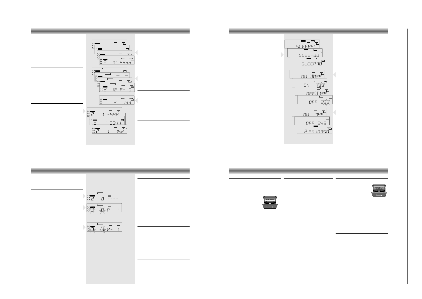
Einstellen des Sleep-Timers
Das Gerät kann zu einem vorher eingestellten
Zeitpunkt abschalten.
So können Sie beim Zuhören ruhig einschlafen.
• Drücken Sie SLEEP auf der Fernbedienung.
– Im Display erscheint SLEEP90.
• Durch wiederholtes Drücken der SLEEP-Taste
kann die Einschlafzeit in zehn-Minuten-Schritten
von 90 Minuten bis “off” reduziert werden.
Timer
Das System kann automatisch zu einer bestimmten
Uhrzeit auf CD- oder TUNER-Betrieb geschaltet
werden und auf diese Weise z.B. als Wecker
dienen.
• Vor dem Einstellen des Timers sicherstellen, daß
die Uhrzeit stimmt.
• Die Lautstärke des Timers entspricht der zuletzt
gewählten Einstellung vor dem Ausschalten des
Gerätes.
• Sofern der Timer nicht ausgeschaltet oder
gelöscht wird, wirkt er jeden Tag zur selben Zeit.
• Werden Sleep-Timer und normaler Timer
gleichzeitig eingestellt, hat die Funktion des
Sleep-Timers Vorrang.
TIMER
➥
FLAT ROCK POPS JAZZ
PRESET EQ
PRESET
FLAT ROCK POPS JAZZ
PRESET EQ
PRESET
➥
MHz
STEREO
FLAT ROCK POPS
JAZZ
PRESET EQ
PRESET
➥
➥
FLAT ROCK POPS JAZZ
PRESET EQ
PRESET
FLAT ROCK POPS JAZZ
PRESET EQ
PRESET
TIMER
FLAT ROCK POPS
JAZZ
PRESET EQ
PRESET
TIMER
FLAT ROCK POPS
JAZZ
PRESET EQ
PRESET
➥
STEREO SLEEP
FLAT ROCK POPS
JAZZ
PRESET EQ
PRESET
STEREO SLEEP
FLAT ROCK POPS
JAZZ
PRESET EQ
PRESET
STEREO SLEEP
FLAT ROCK POPS
JAZZ
PRESET EQ
PRESET
➥
➥
Einstellen des Timers
• Die gewünschte Signalquelle CD oder TUNER
wählen und eine CD einlegen oder einen
Sender einstellen.
• Die Taste TIMER SET drücken.
– Auf dem Display erscheint ‘ON’, die aktuelle Zeit
und die Anzeige der Stunden blinkt.
•
Durch Drücken von SKIP/SEARCH S oder T
wird die Stunde für den Timer-Start eingestellt.
• Die Taste TIMER SET erneut drücken.
– Die Anzeige der Minuten blinkt.
•
Durch Drücken von SKIP/SEARCH S oder T
werden die Minuten für den Timer-Start eingestellt.
• Die Taste TIMER SET erneut drücken.
– Auf dem Display erscheint ‘OFF’ die Zeit und die
Anzeige der Stunden blinkt.
•
Durch Drücken von SKIP/SEARCH S oder T
wird die Stunde für den Timer-Stop eingestellt.
• Die Taste TIMER SET erneut drücken.
– Die Anzeige der Minuten blinkt.
•
Durch Drücken von SKIP/SEARCH S oder T
werden die Minuten für den Timer-Stop eingestellt.
• Die Taste TIMER SET erneut drücken.
– Im Display erscheint zunächst die Startzeit, dann
die Stopzeit und anschließlich wieder die
ursprüngliche Anzeige.
• Die Taste TIMER MODE drücken.
– Das Symbol TIMER leuchtet im Display.
• Die Taste ON/OFF y drücken, um die Anlage
auszuschalten.
Mit SLEEP TIMER kann das Gerät ebenfalls zu
einem vorher eingestellten Zeitpunkt abgeschaltet
werden.
Cassettenwiedergabe
Wiedergabe einer Cassette mit Deck A oder Deck B
• Drücken Sie TAPE, um das Cassettendeck zu
selektieren.
•
Drücken Sie auf
9//
von Deck A oder
Deck B, um das Cassettenfach zu öffnen.
• Legen Sie eine bespielte
Cassette ein.
• Zum Starten des Abspielens
auf B drücken.
• Die Lautstärke mit VOLUME
einstellen.
– Am Bandende stoppt die Wiedergabe.
• Für kurzzeitige Unterbrechungen auf ;drücken.
• Erneut auf;drücken, wenn die Wiedergabe
fortgesetzt werden soll.
• Zum Stoppen auf 9// von Deck A oder
Deck B drücken.
–
Am Bandende wird die B-Taste entriegelt.
Gestaffeltes Abspielen (Deck 2 gefolgt von Deck 1)
• Beide
9//
-Tasten drücken und in beide Decks
eine bespielte Cassette einlegen.
• Drücken Sie auf B von Deck B und auf ; und B
von Deck A.
– Deck B startet mit der Wiedergabe.
– Im Moment, wo Deck B stoppt (am Bandende),
rastet ; aus und Deck A startet mit der
Wiedergabe.
• Zum Stoppen auf 9// von Deck A oder
Deck B drücken.
– Das Gerät wird damit ausgeschaltet.
Hinweis
Wenn auf 9// auf Deck B gedrückt wird, startet
Deck A das Abspielen.
CASSETTENDECK
Aufnahme (Deck A)
Aufnahme vom CD-Spieler
• Öffnen Sie das Cassettenfach von Deck 1 mit
9//.
• Legen Sie eine Leercassette ein.
• Durch zweimaliges Drücken von CD B; wird
die Betriebsart “Pause” gewählt.
• Drücken Sie die Taste 0 RECORD.
– Der CD-Spieler startet automatisch.
– Wenn das Bandende erreicht ist, werden die
Recorder-Tasten freigegeben.
• Die Taste 9// drücken, wenn die Aufnahme
vor Erreichen des Bandendes gestoppt werden
soll.
Aufnahme vom Radio
• Öffnen Sie das Cassettenfach von Deck A mit
9//.
• Legen Sie eine Leercassette ein.
• Drücken Sie die Taste TUNER.
• Auf den gewünschten Radiosender abstimmen.
•
Drücken Sie auf ; und
0 RECORD
von Deck A.
– Die B-Taste senkt sich automatisch.
•
Lösen Sie ;, um die Aufnahme zu beginnen.
– Wenn das Bandende erreicht ist, werden die
Recorder-Tasten freigegeben.
• Die Taste 9// drücken, wenn die Aufnahme
vor Erreichen des Bandendes gestoppt werden
soll.
Automatische Aussteuerungskontrolle
Dieses Gerät ist ausgestattet mit einer automatischen
Pegelaussteuerungskontrolle, die elektronisch den
Aufnahmepegel von jeder Signalquelle anpaßt.
Deshalb werden Aufnahme oder Kopieren nicht
von den Einstellungen der Lautstärke, DSC oder
von BASS BOOST beeinflußt.
DUBBING - Kopieren von Deck B nach A
• Drücken Sie die Taste TAPE.
•
Beide 9//-Tasten drücken und
eine bespielte Cassette in
Deck B und eine bespielbare
Cassette in Deck A einlegen.
• Drücken Sie an Deck A die
Taste ; und dann 0 RECORD.
–Bsenkt sich automatisch.
• Drücken Sie
B
an Deck B; ; an Deck A wird
automatisch gelöst und der Kopiervorgang
beginnt.
– Am Bandende der ersten Seite stoppt Deck A.
– Das Band in Deck B spielt eine Seite der
Cassette ab und stoppt.
• Zum vorzeitigen Stoppen beide 9//-Tasten
drücken.
Vollautomatischer Stop
• Deck A und B haben einen eingebauten vollautomatischen Stopmechanismus. Dieser stoppt
das Band, wenn das Ende erreicht wird in jedem
Modus.
• Ein vorzeitiges Beenden wird durch Drücken der
Taste 9// herbeigeführt.
Page 12

Allgemeiner Teil / General Section KM 13
1 - 12 GRUNDIG Service
Operating Hints This chapter contains excerpts from the operating instructions. For further particulars please refer to the appropriate user instructions the part number of which is indicated in the
relevant spare parts list.
Changing batteries
If the range of your infrared remote control seems to
decrease, or if certain functions can no longer be
carried out, you should replace the batteries.
• Two mignon 1.5Volt LR03, size AAA batteries
are required.
• To change the batteries, open the compartment
on the back of the remote control. Ensure that the
batteries are inserted properly (note the markings
in the compartment).
Note on Environmental Protection
Do not throw exhausted batteries in the household
refuse. Hand over the old batteries to your dealer
or public collecting points when buying new ones.
General functions
ON/OFF y - to turn the unit on and off.
MUTE - to turn off the sound. Press again to restore
the sound.
VOLUME C/D - Press the D button to decrease the
volume and press the C button to increase the
volume. Each time the unit is turned on, the volume
is automatically set to the previous level.
B.BOOST - to switch on and off dynamic bass
boost.
SLEEP - to set a time for the unit to switch off
automatically.
RADIO functions
TUNER/BAND - to select the TUNER function and
to
select between the tuner bands AM and FM.
FM MODE - to select FM auto (stereo) or mono
reception.
PRESET 34- to cycle through the 30 presets in the
FM and AM band.
CD functions
CD 2/; - to select the CD function and to start
playback. Press again during playback to
temporarily stop playback. Press again to resume
playback.
STOP 9 - to stop CD playback or to clear a
program.
DISC SELECT
123
- to select one of the discs
to be played.
M.SCAN - to play the first ten seconds of each
track on the discs in the tray.
SKIP S/Q - Press briefly to skip to the
beginning of the present track. Press again to skip
to the beginning of previous tracks.Press and hold
during playback to search backwards through the
disc.
SKIP R/T - Press briefly to skip to the
beginning of the next track. Press and hold during
playback to search forward through the disc.
RANDOM - to activate random playback.
REPEAT - to playback one track, one disc or all
three discs repeatedly.
TIME - to change the information shown on the
display between elapsed playing time, remaining
time of the current track or remaining time of the
disc being played.
PROGRAM - to program tracks to be played.
CLEAR - to erase a programmed track.
CHECK - to review the contents of a programme.
TAPE functions
TAPE - to select the TAPE function.
REMOTE CONTROL
FRONT PANEL CONTROLS
Amplifier controls
ON/OFF y – Switches the unit on or to standby
(the 6 lights always up when the unit is connected
to the mains).
REMOTE SENSOR – To receive signals from the
remote control.
BASS BOOST – To enhance the bass response.
DSC – Digital Sound Control - to select the desired
sound effect: JAZZ, POP, ROCK or FLAT.
VOLUME – To adjust the volume level.
CD B;/TAPE/TUNER – To activate the set and
select the desired programme source. When
CD B; is pressed, playback will start immediately
in case a CD is inserted.
p – connection for headphones.
Radio controls
TUNER –
To switch on the radio and to select the
waveband AM or FM.
PRESET CD – To select preset stations.
SKIP/SEARCH ST– Press the T button
to tune to higher frequencies and the S button to
tune to lower frequencies.
MEMORY –To program preset stations.
AUTO STORE –To store up to 30 stations
automatically.
Clock/Timer controls
S SKIP/SEARCH T – to set the hour and
minutes for the clock or timer.
CLOCK – to set or display the clock.
TIMER SET/CLOCK LIGHT – to set or display the
On/Off time, and to light up the display for
checking the clock when the power is off.
TIMER MODE – to activate the timer.
S SKIP/SEARCH T
C
D
TUNER
TAPE
CD
aB;
9
0 RECORD
Q
R
9//
;
Q
R
9//
;
B
B
3
1
2
DECK A
DECK B
BASS
BOOST
PHONES
PRESET
DSC
ON/OFF y
REMOTE
SENSOR
VOLUME
SKIP/
SEARCH
/
OPEN/CLOSE
CLOCK
MEMORY
DISC
SELECT
TUNER
CD
TAPE
TIMER
CD PROGRAM
AUTO STORE
PRESET
PRESET
BASS BOOST
REMOTE SENSOR
12
3
MEMORY
AUTO STORE
CD PROGRAM
MODE
SET
DSC
a/
OPEN/CLOSE
DIGITAL SOUND CONTROL
3 - DISC CD CHANGER
HIFI STEREO MINI SYSTEM
KM13
CD SYNCHRO RECORD
DECK A
FULL AUTOMATIC STOP
TIMER
CLOCK
VOLUME
ON/OFF
DECK B
RECORD/PLAYBACK
PLAYBACK
30 STATIONS
PRESET MEMORY
DISC SELECT
CONTROLS OPERATION
p (Headphone) Jack
A headphone jack is provided for private listening.
•
To listen to the unit with headphones, set the
volume
to minimum and insert the 3.5mm mini
plug from the headphones into the p jack.
– The speakers will
be disconnected when the plug
is inserted in the jack.
Display light
• Press CLOCK LIGHT when the power is off.
– The background light of the display will be
turned on during 5 seconds
CD player controls
CD B; – to switch on the CD player and to start
or interrupt CD play.
9 – to stop CD playback or to clear a program.
S SKIP/SEARCH T – press briefly to skip to
previous and next tracks. Press and hold during
playback to search forward or backward through
the selected disc.
CD PROGRAM – to program track numbers in the
memory.
OPEN/CLOSE / – to open and close the CD tray.
DISC SELECT 1~3 – to turn the rotary CD tray in
order to select a CD.
Cassette deck controls
controls for DECK A
0 RECORD
– to start recording.
2 – to start cassette playback.
5 – fast rewind.
6 – fast forward.
9// – to stop and eject the cassette.
; – to interrupt playback.
controls for DECK B
2 – to start cassette playback.
5 – fast rewind.
6 – fast forward.
9// – to stop and eject the cassette.
; – to interrupt playback.
To turn the unit on and off
• Press the ON/OFF y button on the main unit
or on the remote control to turn the unit on.
• Press ON/OFF y again to turn the unit off.
• When the unit is turned off either by the
remote control or the main unit, the standby 6
indicator will light up.
Note: Even if you switch your unit off, it remains
connected to the mains power supply. If you
want to completely disconnect the unit from the
power supply, remove the plug from the mains
socket.
Automatic Power on
• If you press TUNER, CD B; or TAPEon the
main unit, the unit will be switched on automatically and the respective source is chosen.
Setting the clock
• Press while the unit is switched off (standby) the
CLOCK button during 3 seconds.
–‘--:--’ appears on the display.
•
Set the hour with SKIP/SEARCH S and
T.
• Press the CLOCK button again.
• Set the minutes with SKIP/SEARCH S and
T.
• Press the CLOCK button one more time.
– The clock starts working.
To check the clock
• Press the CLOCK button.
– The clock is displayed for 5 seconds
VOLUME control
• Turn the VOLUME control to the right or left to
increase or decrease the volume level.
• You can also press VOLUME C or D on the
remote control.
– The display will show the volume level
– When the unit is turned on, the volume will be
set to the previous level.
MUTE
• Press the MUTE button on the remote control to
temporarily switch off the sound
– MUTE blinks on the Display.
• Press the MUTE button again to restore the sound
– MUTE will disappear.
BASS BOOST
• Press BASS BOOST to enhance the bass
response.
– BASS BOOST lights up on the display.
• Press BASS BOOST again to switch the function
off.
Digital Sound Control
The DSC feature creates a realistic atmosphere for
the style of music you select.
• To enjoy a special sound effect, press several
time the DSC button.
– A frame on the display will show the selected
effect: FLAT, ROCK, POPS or JAZZ.
SOUND CONTROL RADIO
Radio reception
• Press TUNER to select the radio and the desired
waveband. AM or FM.
• Press FM MODE on the remote control to select
FM auto (stereo) or mono reception.
– When stereo is selected, the MONO indicator
will disappear. The STEREO indicator lights up
when receiving a stereo station.
• Press SKIP/SEARCH S or T for one
second, the frequency display will change until a
station with sufficient strength is found.
• If you wish to tune to a weak station, press
SKIP/SEARCH S or T repeatedly until the
display shows the right frequency and/or
optimum reception has been obtained.
Storing Preset Stations
You can store up to 30 stations in the FM and AM
waveband in the memory.
Automatic programming
• Press AUTO STORE. MEMORY blinks on the
display. The tuner will start searching for stations
first in the FM band and then in the AM band.
It will stop searching when all the available stations
are stored or the memory for 30 stations is used.
Manual programming
• Tune to the station to be programmed.
• Press MEMORY. MEMORY blinks on the display.
• Press the PRESET CD buttons to select a preset
number
• Press MEMORY again to store the station.
– PRESET appears on the display
• Repeat above procedure for each station to be
stored.
• If you wish to listen to a stored station, select the
preset number by pressing PRESET CD.
MHz
MEMORY STEREO
FLAT ROCK POPS
JAZZ
PRESET EQ
➥
MHz
STEREO
FLAT ROCK POPS
JAZZ
PRESET EQ
PRESET
STEREO B.BOOST
FLAT ROCK POPS JAZZ
PRESET EQ
MHz
FLAT ROCK POPS
JAZZ
PRESET EQ
MONO
➥
MHz
STEREO
FLAT ROCK POPS
JAZZ
PRESET EQ
➥
STEREO B.BOOST
FLAT ROCK POPS
JAZZ
PRESET EQ
POWER
M.SCAN
RANDOM
PROGRAM
TUNER/BAND
CD
2
1
3
SKIP
TIME
T
REPEA
CHECK
CLEAR
PRESET
B.BOOST
TAPE
FM MODE
SLEEP
VOLUME
MUTE
Page 13

KM 13 Allgemeiner Teil / General Section
GRUNDIG Service 1 - 13
Selecting a different track
• By pressing repeatedly SKIP/SEARCH T you
can skip to the beginning of next tracks and by
pressing repeatedly S SKIP/SEARCH you can
skip to the beginning of preceding tracks.
• If you press S SKIP/SEARCH only once, you
skip to the beginning of the current track.
Fast search
Fast search can be activated during playback or in
the pause mode.
• By keeping SKIP/SEARCH S or T pressed,
you activate the fast search in the corresponding
direction.
– During the fast search procedure you can listen
to the tracks at a reduced volume.
• Normal playback will continue as soon as you
release S or T.
Changing display indication
• Press TIME on the remote control whenever you
want to know the remaining playing time of the
track being played.
• Press TIME again if you wish to know the
remaining playing time of the entire CD (or CD
programme).
• Press TIME again if you wish to return to the
elapsed playing time indication of the current
track
CD PLAYER
➥
➥
➥
FLAT ROCK POPS JAZZ
PRESET EQ
DISC
1
2
3
B
FLAT ROCK POPS JAZZ
PRESET EQ
DISC
1
2
3
B
FLAT ROCK POPS JAZZ
PRESET EQ
DISC
1
2
3
B
FLAT ROCK POPS JAZZ
PRESET EQ
RANDOM
DISC
1
2
3
B
➥
➥
➥
FLAT ROCK POPS JAZZ
PRESET EQ
REPEAT 1
DISC
1
2
3
FLAT ROCK POPS JAZZ
PRESET EQ
DISC
REPEAT 1
DISC
1
2
3
FLAT ROCK POPS JAZZ
PRESET EQ
ALLDISC
REPEAT 1
DISC
1
2
3
➥
PROGRAM
FLAT ROCK POPS
JAZZ
PRESET EQ
DISC
1
2
3
PROGRAM
PROGRAM
PROGRAM
➥
➥
➥
FLAT ROCK POPS JAZZ
PRESET EQ
REPEAT 1
DISC
1
2
3
FLAT ROCK POPS JAZZ
PRESET EQ
DISC
REPEAT 1
DISC
1
2
3
FLAT ROCK POPS JAZZ
PRESET EQ
ALLDISC
REPEAT 1
DISC
1
2
3
➥
FLAT ROCK POPS JAZZ
PRESET EQ
DISC
1
2
3
Repeat function
If you want to listen to CDs or a CD programme
more than once without having to start playback
again, you can do so with the REPEAT function.
• Press REPEAT on the remote control.
– You can change the repeat status from ‘REPEAT
1’ to ‘REPEAT 1 DISC’ to ‘REPEAT ALL DISC’ to
'REPEAT off'.
– REPEAT 1: A specific title is played over and
over again.
– REPEAT 1 DISC: The current CD is repeated from
the beginning till the end of the CD´s last title.
– REPEAT ALL DISC: All CD’s are repeated from
the beginning till the end.
– REPEAT PROGRAM: When REPEAT is pressed in
the programme mode, the programmed track(s)
on one disc or on all discs will be repeated.
Random playback
You can play all the titles on all CDs in random
order.
• To do so, press RANDOM on the remote control.
– 'RANDOM' appears in the display.
– The titles and discs are played in random order.
• Press RANDOM again to resume normal
playback.
Scan function
• Press M SCAN on the remote control to play the
first ten
seconds of each track on all discs in the
CD tray.
• Press M.SCAN again while a desired track is
playing to resume normal playback.
CD PROGRAMMING
By programming the player you can play up to 32
tracks in any desired order.
Storing a programme
• Insert CD(s) (see LOADING CD’s).
• Press the CD PROGRAM button
– The PROGRAM indicator will light up,
‘O ----’ will appear in the display.
• Press the desired DISC SELECT button. The
number of the selected disc starts blinking and
‘0P- 1’ will be displayed.
• Press SKIP/SEARCH S or T to select the
first desired track.
– The number next to the ‘P’ will count up or down
indicating the first programmed track.
For example, if track 3 is selected, ‘3P- 1’ will
be displayed.
• After the track is selected, press the
CD PROGRAM button again.
– The display will stop blinking indicating that you
can now programme the next track.
• Repeat above mentioned steps to program
additional tracks.
– Up to 32 tracks can be programmed. If you try
to program more than 32 tracks, ‘FULL’ will
appear on the display.
Reviewing the program
• After programming you can press CHECK on the
remote control repeatedly to review the
programmed tracks.
PROGRAM
FLAT ROCK POPS JAZZ
PRESET EQ
DISC
1
2
3
PROGRAM
FLAT ROCK POPS JAZZ
PRESET EQ
DISC
1
2
3
PROGRAM
FLAT ROCK POPS JAZZ
PRESET EQ
DISC
1
2
3
Playing a programme
• Press CD B; to play the programmed tracks.
• Adjust the VOLUME control as desired.
– Play stops at the end of the programme
sequence or when
9
is pressed.
– Press CD PROGRAM again, the PROGRAM
indicator will disappear (for normal playback).
However, the programme sequence will remain
in memory.
• To play the program sequence again, press first
the CD PROGRAM button.
– The PROGRAM indicator will light up.
• Then press CD B;.
Adding tracks to a programme
• To add a track to the programme, press the CD
PROGRAM button and the last programme
number will be displayed.
• Programme the next track according to the
normal programming procedure.
– New tracks can only be added at the end of the
programme.
– Also, tracks cannot be added to the programme
during playback.
Deleting programmed tracks
• To delete all programmed tracks from the
memory, press the 9button during 3 seconds.
• You can also delete the last track from the
programme by pressing CLEAR on the remote
control.
Setting the Sleep Timer
You can let the unit switch off at a preset time
period.
This allows you to fall asleep while listening to
music.
• Press SLEEP on the remote control.
– SLEEP90 appears on the display
• The ‘sleep’ time can be reduced in 10 minutes
steps from 90 minutes to ‘off’, by pressing
repeatedly the SLEEP button.
Timer
The system can switch on to CD or TUNER mode
automatically at a preset time.
It can serve as an alarm to wake you up.
• Before setting the timer, make sure the clock is
set correctly.
• The volume of the timer will be at the last setting
before the set was switched off.
• The timer works every day on the same time
unless it is switched off or cancelled.
• The volume of the timer will be at the last setting
before the set is switched off.
• If both Sleep Timer and normal Timer are set
simultaneously, the Sleep Timer has the priority in
operation.
TIMER
➥
FLAT ROCK POPS JAZZ
PRESET EQ
PRESET
FLAT ROCK POPS JAZZ
PRESET EQ
PRESET
➥
MHz
STEREO
FLAT ROCK POPS
JAZZ
PRESET EQ
PRESET
➥
➥
FLAT ROCK POPS JAZZ
PRESET EQ
PRESET
FLAT ROCK POPS JAZZ
PRESET EQ
PRESET
TIMER
FLAT ROCK POPS
JAZZ
PRESET EQ
PRESET
TIMER
FLAT ROCK POPS
JAZZ
PRESET EQ
PRESET
➥
STEREO SLEEP
FLAT ROCK POPS
JAZZ
PRESET EQ
PRESET
STEREO SLEEP
FLAT ROCK POPS
JAZZ
PRESET EQ
PRESET
STEREO SLEEP
FLAT ROCK POPS
JAZZ
PRESET EQ
PRESET
➥
➥
Setting the Timer
• Select the desired source CD or TUNER and
insert a CD or select a station.
• Press TIMER SET.
– The display will show ‘ON’, the actual time and
the hour indication flashes.
• Press SKIP/SEARCH S or T to set the hour
for the timer to start.
• Press TIMER SET again.
– The minute indication flashes.
• Press SKIP/SEARCH S or T to set the
minutes for the timer to start.
• Press TIMER SET again.
– The display will show ‘OFF’ the time and the hour
indication flashes.
• Press SKIP/SEARCH S or T to set the hour
for the timer to stop.
• Press TIMER SET again.
– The minute indication flashes.
• Press SKIP/SEARCH S or T to set the
minutes for the timer to stop.
• Press TIMER SET again.
– The display shows the start time, followed by the
stop time and then the original display again.
• Press TIMER MODE
– The display will show the TIMER flag.
• Press ON/OFF y to switch off the set
You can also use the SLEEP TIMER to turn the unit
off at a preset time.
Cassette playback
Playback on deck A or B
• Press TAPE to switch the system on and to
select the cassette deck.
• Press 9// on deck A and/or B to open the
cassette holder.
• Insert a recorded cassette.
• Press B and playback will
start.
• Adjust the sound using the
VOLUME control.
– Playback stops when the tape in the deck
reaches the end.
• For brief interruptions, press ;.
–
To restart playback, press this button once more.
•
To stop, press 9// on deck A or B
– When the end of the tape is reached the B
button is released.
Continuous play
•
Press both 9//
buttons and insert a recorded
cassette in both decks.
• Press B on deck B. Then press ; and B on
deck A.
– Playback begins with deck B.
– Playback stops when the tape in deck B
reaches the end.
– The ; button will automatically be released
and playback continues with deck A.
• To stop, press 9// on deck A and B.
– The set is then switched off.
Note: When you press 9// on deck B,
playback will continue with deck A.
CASSETTE DECK
Recording (deck A only)
Recording from the CD-player
•
Press 9// to open the cassette holder of
deck A.
• Insert a blank cassette.
• Press the CD B; button twice to select the
pause mode.
•
Press
0 RECORD
– The CD player starts automatically.
– When the end of the tape is reached, the
recording will stop.
•
Press
9//
if you want to stop recording before
the end of the tape.
Recording from the radio
•
Press 9// to open the cassette holder of
deck A.
• Insert a blank cassette.
• Press the TUNER button.
• Tune to desired radio station
• Press the ; button and then the
0 RECORD button on Deck A.
–
The B button will go down automatically.
•
Release the ; button to begin recording.
– When the end of the tape is reached, the
recording will stop.
•
Press
9//
if you want to stop recording before
the end of the tape.
Automatic level control
This unit has a built-in automatic level control circuit
that electronically adjusts the recording level from
any source. Therefore, recording and dubbing are
not affected by the settings of the VOLUME, DSC,
or BASS BOOST controls.
DUBBING - Copying from deck B to A
• Press the TAPE button.
•
Press both 9//
buttons and
insert a recorded cassette into
deck B and a cassette which
is suited for recording into
deck A.
• Press the ; button and then
the 0 RECORD button on Deck A.
–
The B button will go down automatically.
• Press the Bbutton on Deck B; the ; button on
Deck A will be released and dubbing will start.
– The tape in Deck A will stop at the end of the
first side.
– The tape in Deck B will play one side of the
tape and then stop.
• To stop dubbing before the end of the tapes,
press both 9// buttons.
Full automatic stop
• Decks A and B have a built-in Full Automatic
Stop System that stops the tape when it reaches
the end in all modes.
• To stop the tape before it reaches the end, press
the 9// button.
Page 14

Abgleichvorschriften / Adjustment Procedures KM 13
Abgleichvorschriften
D
1. Tuner
Meßgeräte: Wobbler, Meßsender, Stereocoder, Oszilloskop, DC-Voltmeter, NF-Voltmeter
Hinweis: Das Frontend ist ein komplett abgeglichener Baustein. Nur das ZF-Filter muß dem ZF-Verstärker angeglichen werden (1).
Abgleich Vorbereitung Abgleichvorgang
1. MW-ZF
2. MW-Oszillator
3. MW-Vorkreis
4. FM-ZF-Filter
5. FM-Oszillator
6. Stereo
MW; am Gerät 522kHz einstellen.
Wobbler 450kHz an Antennenbuchse.
Ua nur so groß, daß das Signal gerade erkennbar ist;
f
= 400Hz; m = 30%;
mod
Oszilloskop an Lautsprecherausgang.
MW;
DC-Voltmeter an Meßpunkt TP2 (VT).
MW;
Meßsender an Antennenbuchse.
Ua nur so groß, daß das Signal gerade erkennbar ist;
f
= 400Hz; m = 30%;
mod
NF-Voltmeter an Lautsprecherausgang.
FM, 98MHz.
Wobbler 98MHz an Antennenbuchse. Pegel ca. 100µV
Oszilloskop an Meßpunkt TP1 (VT).
FM;
DC-Voltmeter an Meßpunkt TP2 (VT).
FM;
Stereocoder 98MHz an Antennenanschluß.
Ua = 26dBµV; f
= 19kHz;
mod
2. Cassettenteil
Meßgeräte: NF-Voltmeter, Frequenzzähler, Testkassette 449 Sach-Nr.: 35079-019.00
Mit T102 auf NF-Maximum abgleichen.
Mit L105 bei 522kHz auf 1,2V ±0,05V.
Kontrolle bei 1629kHz 8,0V ±0,5V.
Wechselweise mit L104 bei 603kHz und mit TC102 bei
1404kHz auf NF-Maximum abgleichen.
Mit Filter a auf Maximum und Symmetrie einstellen.
Kontrolle bei 87,5MHz 1,6V ±0,05V.
Kontrolle bei 108MHz 8,0V ±0,5V.
Mit SFR101 die Stereo-Schwelle (Ua = 26dBµV) so
abgleichen, daß die Stereo-Anzeige im Display noch
aufleuchtet.
Abgleich Vorbereitung Abgleichvorgang
1. Azimut
2. Geschwindigkeit
Die Einstellschrauben sind durch Aussparungen unter
den Cassettenklappen zugänglich.
Testkassette 449 Pegeltonteil 8kHz wiedergeben
NF-Voltmeter an NF-Ausgang.
Tape, Fe.
Testkassette 449 Pegeltonteil 3150Hz wiedergeben
Frequenzzähler an NF-Ausgang
Mit Schraube A auf NF-Maximum
abgleichen.
Mit SFR201 auf 3110Hz - 3240Hz einstellen.
3. CD-Teil
Meßgeräte: DC-Voltmeter, Oszilloskop, Test-CD Sachnr.: 72008-376.00
Abgleich Vorbereitung Abgleichvorgang
1. RF Gain
2. E-F-Balance
CD-Spieler auf STOP.
DC-Voltmeter an Meßpunkt CN12.
Auf der Front-Platte, wie auf Seite 3 - 15 abgebildet, mit
einer Diode (1N4148) die Pins der Steckverbindung
CN601 Pin 19 (Anode) und Pin 8 (Katode) verbinden
und die Tasten „CD CHECK“ und „REPEAT“ einlöten.
Oszilloskop an Meßpunkt CN02 (+/-).
Test-CD einlegen und wiedergeben.
Die eingebauten Tasten „CD CHECK“ und „REPEAT“
gleichzeitig drücken und VR02 abgleichen.
Nach Beendigung des Abgleichvorgangs, die Taste
„STOP“ drücken und die Diode entfernen.
Mit VR01 auf 0V ±20mV abgleichen.
Mit VR02 die Amplitude des Signals symmetrisch zur
Null-Linie abgleichen (A=B).
A
2 - 1 GRUNDIG Service
Page 15

Abgleichvorschriften / Adjustment ProceduresKM 13
Adjustment Procedures
GB
1. Tuner
Test equipment: Sweep Generator, Test Generator, Stereo Coder, Oscilloscope, DC Voltmeter, AF Voltmeter
Note: The frontend is a completely preadjusted module. Only the IF filter must be adjusted to the IF amplifier (1).
Adjustment Preperation Adjustment Procedure
1. AM IF
2. AM Oscillator
3. AM Aerial
Bandpass
4. IF Filter
5. FM Oscillator
6. Stereo
MW; set the tuner to 522kHz.
Sweep generator 450kHz at aerial input.
Ua as low as possible; f
Oscilloscope at loudspeaker output.
MW;
DC voltmeter at test point TP2 (VT).
MW;
Test generator at aerial input.
Ua as low as possible; f
AF voltmeter at loudspeaker output.
FM, 98MHz.
Sweep generator 98MHz to aerial socket. Level approx.
100µV.
Oscilloscope at test point TP1 (VT).
FM;
DC voltmeter at test point TP2 (VT).
FM;
Stereo coder 98MHz at aerial input.
Ua = 26dBµV; f
mod
= 400Hz; m = 30%;
mod
= 400Hz; m = 30%;
mod
= 19kHz;
Adjust T102 for AF maximum.
Adjust L105 at 522kHz for 1.2V ±0.05V.
Check at 1629kHz 8.0V ±0.5V.
Adjust alternately L104 at 603kHz and TC102 at
1404kHz for AF maximum.
Adjust Filter a to maximum and symmetry.
Check at 87.5MHz 1.6V ±0.05V.
Check at 108MHz 8.0V ±0.5V.
With SFR101 adjust the stereo threshold (Ua = 26dBµV)
so that the stereo indication still illuminates on the
display.
2. Cassette Part
Test equipment: AF Voltmeter, Frequency Counter, Test Cassette 449 Part No.: 35079-019.00
Adjustment Preperation Adjustment Procedure
1. Azimuth
2. Tape Speed
Access to the screws is gained through holes below the
cassette flaps.
Play Test Cassette 449, 8kHz part.
AF voltmeter at AF output.
Tape, Fe.
Play Test Cassette 449, 3150Hz part.
Frequency counter at AF output.
Adjust screw A for AF maximum.
Adjust SFR201 for 3110Hz - 3240Hz.
3. CD Part
Test equipment: DC Voltmeter, Oscilloscope, Test CD Part No.: 72008-376.00
Adjustment Preperation Adjustment Procedure
1. RF Gain
2. E-F-Balance
Set CD player to STOP.
DC voltmeter at test point CN12.
Connect a diode (1N4148) between pin 19 (anode) and
pin 8 (cathode) of connector CN601 on the Front Panel
as shown on page 3 - 15, and solder the buttons
„CD CHECK“ and „REPEAT“ on to the panel.
Oscilloscope to test point CN02 (+/-).
Load the test CD and play.
Depress the soldered buttons „CD CHECK“ and
„REPEAT“ simultaneously and adjust VR02.
On completion of this adjustment press the „STOP“
button and remove the diode.
Adjust VR01 for 0V ±20mV.
Set VR02 so that the signal amplitude is symmetrical
to the datum line (A=B).
A
GRUNDIG Service 2 - 2
Page 16

Abgleichvorschriften / Adjustment Procedures KM 13
Abgleichlagepläne / Alignment Layouts
1. Tuner
FM FRONT END
FM
ANTENNA
MW
ANTENNA
L101
L104
TC102
L105
a
TP2
T102
VT
SFR101
T101
TP1
IF
Tuner-Platte
Tuner Board
2. Cassette
SPEAKER JACK
3. CD
SFR201
Hauptplatte
Main Board
CN12
CN02
VR01
VR02
CD-Decoder-Platte
CD Decoder Board
2 - 3 GRUNDIG Service
19
8
121
CN09
Page 17

GRUNDIG Service 3 - 1
Blockschaltplan – KM 13 / Block Diagram – KM 13
Platinenabbildungen und Schaltpläne / Layout of PCBs and Circuit Diagrams
Platinenabbildungen und Schaltpläne / Layout of PCBs and Circuit DiagramsKM 13
Page 18

3 - 2 GRUNDIG Service
Platinenabbildungen und Schaltpläne / Layout of PCBs and Circuit Diagrams KM 13
Blockschaltplan – CD-Teil / Block Diagram – CD Part
Page 19

Verdrahtungsplan / Wiring Diagram
Platinenabbildungen und Schaltpläne / Layout of PCBs and Circuit Diagrams Platinenabbildungen und Schaltpläne / Layout of PCBs and Circuit DiagramsKM 13 KM 13
GRUNDIG Service GRUNDIG Service
3 - 3 3 - 4
Page 20

Platinenabbildungen und Schaltpläne / Layout of PCBs and Circuit Diagrams Platinenabbildungen und Schaltpläne / Layout of PCBs and Circuit Diagrams KM 13KM 13
Schaltplan – Tuner / Circuit Diagram – Tuner
3 - 5 3 - 6
GRUNDIG Service GRUNDIG Service
TO MAIN PCB CN101 PAGE 3 - 17
Page 21

Platinenabbildungen und Schaltpläne / Layout of PCBs and Circuit Diagrams Platinenabbildungen und Schaltpläne / Layout of PCBs and Circuit DiagramsKM 13 KM 13
Platinenabbildungen – Tuner-Platte / Layout of PCBs – Tuner Board
Ansicht von der Bestückungsseite / View of component side Ansicht von der Lötseite / View of solder side
GRUNDIG Service GRUNDIG Service
3 - 7 3 - 8
Page 22

Platinenabbildungen und Schaltpläne / Layout of PCBs and Circuit Diagrams Platinenabbildungen und Schaltpläne / Layout of PCBs and Circuit Diagrams KM 13KM 13
Schaltplan / Circuit Diagram: -LED-Platte / LED Board -CD-Decoder-Platte / CD Decoder Board
-Motorplatte / Motor Board -Schalterplatten A - D / Switch Boards A - D
TO MOTOR PCB
CN06-
PAGE 3 - 10
TO SWITCH D PCB
CN05-
PAGE 3 - 10
TO FRONT PCB
CN601
PAGE 3 - 14
º
º
TEST POINT TEST POINT
º
º
º
º
º
º
TO MAIN PCB
CN08PAGE 3 - 17
ººº
TO CD DECODER PCB CN05
PAGE 3 - 10
º
º
TO CD DECODER PCB CN06
PAGE 3 - 10
º
º
3 - 9 3 - 10
GRUNDIG Service GRUNDIG Service
Page 23

Platinenabbildungen und Schaltpläne / Layout of PCBs and Circuit Diagrams Platinenabbildungen und Schaltpläne / Layout of PCBs and Circuit DiagramsKM 13 KM 13
Platinenabbildungen / Layout of PCBs: -LED-Platte / LED Board -CD-Decoder-Platte / CD Decoder Board
-Motorplatte / Motor Board -Schalterplatten A - D / Switch Boards A - D
Bauteile der Bestückungsseite (Sicht von der Lötseite) / Components of component side (View of Solder side) Ansicht von der Lötseite / View of solder side
GRUNDIG Service GRUNDIG Service
3 - 11 3 - 12
Page 24

Platinenabbildungen und Schaltpläne / Layout of PCBs and Circuit Diagrams Platinenabbildungen und Schaltpläne / Layout of PCBs and Circuit Diagrams KM 13KM 13
Schaltplan / Circuit Diagram: -Front-Platte / Front Board
-RC-Empfängerplatte / Remote Receiver Board
TO MAIN PCB
CN301
PAGE 3 - 18
º
º
º
TO CD DECODER PCB
CN09
PAGE 3 - 10
3 - 13 3 - 14
GRUNDIG Service GRUNDIG Service
Page 25

Platinenabbildungen und Schaltpläne / Layout of PCBs and Circuit Diagrams Platinenabbildungen und Schaltpläne / Layout of PCBs and Circuit DiagramsKM 13 KM 13
Platinenabbildungen / Layout of PCBs: -RC-Empfängerplatte / Remote Receiver Board
-Front-Platte / Front Board
Ansicht von der Bestückungsseite / View of component side
Ansicht von der Lötseite / View of solder side
CD CHECK KEY
REPEAT KEY
(Tasten nur für CD-Abgleich notwendig)
(Buttons only necessary for CD adjustment)
1 21
8
GRUNDIG Service GRUNDIG Service
1N4148
19
(Diode nur für CD-Abgleich notwendig)
(Diode only necessary for CD adjustment)
3 - 15 3 - 16
Page 26

Platinenabbildungen und Schaltpläne / Layout of PCBs and Circuit Diagrams Platinenabbildungen und Schaltpläne / Layout of PCBs and Circuit Diagrams KM 13KM 13
Schaltplan / Circuit Diagram:
-Aufnahmeschalterplatte / Record Switch
Board
-Hauptplatte / Main Board
-Trafoplatte / Transformer Primary Board
TO CD DECODER PCB
CN08
PAGE 3 - 10
TO TUNER PCB CN101
PAGE 3 - 6
TO FRONT PCB
CN301
PAGE 3 - 13
PAGE 3- 18
TO MAIN PCB CN401
CN401-
PAGE 3 - 18
TO AC POWER SUPPLY PCB
º
º
º
º
º
º
º
º
º
º
º
º
º
º
º
º
º
º
º
º
º
º
º
º
º
º
º
º
º
º
º
º
º
3 - 17 3 - 18
GRUNDIG Service GRUNDIG Service
Page 27

Platinenabbildungen und Schaltpläne / Layout of PCBs and Circuit Diagrams Platinenabbildungen und Schaltpläne / Layout of PCBs and Circuit DiagramsKM 13 KM 13
Platinenabbildungen / Layout of PCBs: -Trafoplatte / Transformer Primary Board -Hauptplatte / Main Board
-Aufnahmeschalterplatte / Record Switch Board
Ansicht von der Bestückungsseite / View of component side
GRUNDIG Service GRUNDIG Service
3 - 19 3 - 20
Page 28

Platinenabbildungen und Schaltpläne / Layout of PCBs and Circuit Diagrams Platinenabbildungen und Schaltpläne / Layout of PCBs and Circuit Diagrams KM 13KM 13
Platinenabbildungen / Layout of PCBs: -Trafoplatte / Transformer Primary Board -Hauptplatte / Main Board
-Aufnahmeschalterplatte / Record Switch Board
Ansicht von der Lötseite / View of solder side
3 - 21 3 - 22
GRUNDIG Service GRUNDIG Service
Page 29

KM 13 Platinenabbildungen und Schaltpläne / Layout of PCBs and Circuit Diagrams
IC-Block-Diagramme / IC Block Diagrams
IC01 CXA1782BG
IC102 LA1831
GRUNDIG Service 3 - 23
Page 30

Platinenabbildungen und Schaltpläne / Layout of PCBs and Circuit Diagrams KM 13
IC04 CXA2508Q
63
EMPHI
43
LRCK1
45
PGMDI
47
BCK1
6
MUTE
46
BCK
44
BCMD
42
LRCK
41
WDCK
54
C2PO
52
RFCK
58
MNT0
MNT1
MNT3
WFCK
EMPH
GFS
XUGF
GTOP
57
56
64
62
51
49
48
corrector
clock
generator
error
Interface
EFM
demodulator
asymmetry
corrector
D/A
16K RAM
SUB code
Processor
digital
PLL
XTAI
XTAO
Digital Filter
+
1bit DAC
digital
OUT
ZEROL
73 74 66 65
ZEROR
digital
CLV
CPU
Interface
Servo auto
sequencer
69
70
78
77
61
55
27
26
25
24
5
4
3
2
1
22
19
11
10
9
7
17
16
15
NLPWM
LPWM
RPWM
NRPWM
DOUT
XROF
LOCK
MDS
MDP
MON
SQCK
SQSO
EXCK
SBSO
SCOR
XLON
SPOB~D
CLOK
XLAT
DATA
SENS
CLKO
XLTO
DATO
IC03 BA5941FP
20K
–
15
+
+
16
–
20K
20K
–
17
+
+
18
–
20K
Vcc
19
µC
20
21
22
23
24
25
26
27
19.9K 19.9K
+
–
10K
19.9K 19.9K
10K
LEVEL
–
LEVEL
SHIFT
+
–
SHIFT
+–+
SHIFT
LEVEL
–
LEVEL
+
SHIFT
–
20K
20K
20K
20K
–
+
+
–
–
+
+
–
Vcc
MUTE
10K
10K
14
13
12
11
10
9
8
7
6
5
4
3
2
59
IC103 LC7218
1
XIN
24
XOUT
19
FMIN
18
AMIN
2
CE
3
DI
4
CL
DO
5
60RF36
FSTT
C4M
OUT0
38
ASYI
REFERENCE
DIVIDER
1
2
9
39
ASYO
SHIFT REGISTER
40
37
50
29
30
FILO
BIAS
ASYE
XPCK
SYC
6
PHASE DETECTOR
CHARGE PUMP
SWALLOW COUNTER
1/16, 1/17 4BIT
12 BIT PROGRAMMABLE
DIVIDER
LATCH
121110
13 14 17 7 8
OUT3OUT2OUT1
OUT4 OUT5 OUT6 IN0 IN1
FILI
31
28
34
23
13
14
FOK
PCO
CLTV
SEIN
CNIN
Vcc
1
IC02 TC9173P
LC7218
UNIVERSAL
COUNTER
CK SOSI
21
PD1
22
PD2
HCTR
16
LCTR
15
V
20
DD
23
Vss
STB
V
GND
I/O-1
(OP-1)
15
16
DD
1
2
SERIAL I/O
CONTROL CIRCUIT
CY
LATCH
3456
I/O-2
(OP-2)
I/O-3
(OP-3)
I/O-4
(OP-4)
Note: The name in ( ) is the terminal name for TC9174P/F.
I/O-10
(OP-10)
11121314
LATCH
I/O-5
(OP-5)
DRIVER
I/O-9
10
(OP-9)
I/O-8
9
(OP-8)
I/O-7
8
(OP-7)
I/O-6
7
(OP-6)
3 - 24 GRUNDIG Service
Page 31

KM 13 Platinenabbildungen und Schaltpläne / Layout of PCBs and Circuit Diagrams
IC602 TC74HC237AP
SELECT
A
B
C
ENABLE
INPUTS
G1
G2
GL
Y0
Y1
Y2
Y3
Y4
Y5
Y6
Y7
DATA
OUTPUTS
IC601 µPD753017AGC-E03
BASIC
INTERVAL
WATCHDOG
TIMER
INTBT
TI0/P13
PTO0/P20
BUZ/P23
SWSB1/P03
SO/SB0/P02
SCK/P01
INT0/P10
INT1/P11
INT2/P12
INT4/P00
KR0/P60
KR7/P73
TIMER/
EVENT
COUNTER
INTT0 TOUT0
WATCH
TIMER
INTW f
CLOCKED
SERIAL
INTERFACE
INTCSI TOUT0
INTERRUPT
CONTROL
8
BIT SEQ
BUFFER (16)
P0
LC0
TI1/TI2/
ROM *2
MEMORY
CLOCK
OUTPUT
CONTROL
P12/INT2
CLOCK
DIVIDER
TIMER/EVENT
COUNTER *2
fx/2
SYSTEM CLOCK
GENERATOR
SUB MAIN
ALU
DECODER
AND
CONTROL
PT01/P21 PT02/P22/PCL
TIMER/EVENT
COUNTER *1
PROGRAM
COUNTER *1
PROGRAM
TOUT0
INTT2INTT1
CY
STAND BY
CONTROL
SP (8)
SBS
BANK
GENERAL REG.
RAM
DATA
MEMORY
1024 X 4 BITS
CPU CLOCK
f
LCD
PORT0
PORT1
PORT2
PORT3
PORT4
PORT5
PORT6
PORT7
LCD
CONTROLLER
DRIVER
4
4
4
4
4
4
4
4
24
8
4
3
P00-P03
P10-13
P20-23
P30-33
P40-43
P50-53
P60-63
P70-73
S0-S23
S24/BP0S31/BP7
COM0-COM3
V
LC0-VLC2
BIAS
LCDCL/P30
SYNC/P31
IC V
*1. µPD753012, 753016, 753017
*2. ROM
PCL/PT02/P22
X2X1XT1 XT2
DD VSS RESET
GRUNDIG Service 3 - 25
Page 32

Platinenabbildungen und Schaltpläne / Layout of PCBs and Circuit Diagrams KM 13
IC301 LC75392
LT1
LT2
LT3
LT4
L1
(R1)
L2
(R2)
L3
(R3)
L4
(R4)
(RT1)
(RT2)
(RT3)
(RT4)
LTCOM
(RTCOM)
LVRIN
LTOUT
(RVRIN)
(RTOUT)
+
–
LVROUT
(RVROUT)
+
–
Vref
LATCH
CL
DI
CE
IC301 LC75392
L1
(R1)
L2
(R2)
L3
(R3)
L4
(R4)
CONTROL
DECODER
SHIFT REGISTR
V
DD VSS
LT1
LT2
LT3
LT4
(RT1)
(RT2)
(RT3)
(RT4)
LTCOM
(RTCOM)
LTOUT
(RTOUT)
LVRIN
(RVRIN)
LVROUT
(RVROUT)
+
–
+
–
Vref
LATCH
DECODER
CL
DI
CE
3 - 26 GRUNDIG Service
CONTROL
SHIFT REGISTR
V
DD VSS
Page 33

Ersatzteilliste und Explosionszeichnungen / Spare Parts List and Exploded Views Ersatzteilliste und Explosionszeichnungen / Spare Parts List and Exploded ViewsKM 13 KM 13
Ersatzteilliste und Explosionszeichnungen / Spare Parts List and Exploded Views
Explosionszeichnung – KM 13 / Exploded View – KM 13
1
GRUNDIG Service GRUNDIG Service
4 - 1 4 - 2
Page 34

Ersatzteilliste und Explosionszeichnungen / Spare Parts List and Exploded Views Ersatzteilliste und Explosionszeichnungen / Spare Parts List and Exploded Views KM 13KM 13
Explosionszeichnung – CD-Teil / Exploded View – CD Part
2
4 - 3 4 - 4
GRUNDIG Service GRUNDIG Service
Page 35

GRUNDIG Service 4 - 5
1
Ersatzteilliste
Spare Parts List
12 / 97
SACH-NR. / PART NO.: 75.4030-1051
POS. NR. ABB. SACHNUMMER ANZ. BEZEICHNUNG DESCRIPTION
POS. NO. FIG. PART NUMBER QTY.
M01.000 1 75954-062.35 2 FEDER, TUER SPRING DOOR
M02.000 1 75954-506.01 CASSETTENSCHACHT L CASSETTE COMPARTMENT L
M03.000 1 75954-506.02 CASSETTENSCHACHT R CASSETTE COMPARTMENT R
M04.000 1 75954-506.03 FENSTER DISPLAY WINDOW DISPLAY
M05.000 1 75954-506.04 KNOPF VOLUME KNOB VOLUME
M06.000 1 75954-062.40 4 GUMMI, FUSS RUBBER FOOT
M08.000 1 75954-506.05 GEH-VORDERTEIL CABINET FRONT PART
M09.000 1 75954-042.63 2 DAEMPFER DAMPER
M10.000 1 75954-506.06 TUER CD DOOR CD
M12.000 1 75954-506.07 TASTE OPEN/CLOSE KEY OPEN/CLOSE
M14.000 1 75954-506.08 TASTE BASS BOOST KEY BASS BOOST
M16.000 1 75954-062.44 LINSE, POWER LENS POWER
M17.000 1 75954-506.09 KNOPF POWER KNOB POWER
M18.000 1 75954-506.10 TASTEN DISC KEY DISC
M19.000 1 75954-042.52 KOPFHOERERBUCHSE EAR PHONE SOCKET
M21.000 1 75954-506.11 KNOPF SKIP/SEARCH KNOB SKIP/SEARCH
M22.000 1 75954-506.12 TASTEN FUNKTION KEY FUNKTION
M23.000 1 75954-062.48 TASTE, MEMORY/TIMER KEY MEMORY/TIMER
M24.000 1 75954-062.47 KNOPF DSC KNOB DSC
M25.000 1 75954-506.13 TASTE STOP KEY STOP
M33.000 1 75954-062.52 FENSTER, CD WINDOW CD
M41.000 1 75954-506.14 TASTE RECORD L KEY RECORD L
M42.000 1 75954-506.15 TASTE PLAY L KEY PLAY L
M43.000 1 75954-506.16 TASTE RUECKLAUF L KEY REWIND L
M44.000 1 75954-506.17 TASTE VORLAUF L KEY FORWARD L
M45.000 1 75954-506.18 TASTE STOP/EJECT L KEY STOP/EJECT L
M46.000 1 75954-506.19 TASTE PAUSE L KEY PAUSE L
M47.000 1 75954-506.20 TASTE PLAY R KEY PLAY R
M48.000 1 75954-506.21 TASTE RUECKLAUF R KEY REWIND R
M49.000 1 75954-506.22 TASTE VORLAUF R KEY FORWARD R
M50.000 1 75954-506.23 TASTE STOP/EJECT R KEY STOP/EJECT R
M51.000 1 75954-506.24 TASTE PAUSE R KEY PAUSE R
M55.000 1 75954-062.54 LAUFWERK, CASS. ZY-300-FW DRIVE MECHANISM CASS ZY-300-FW
M55.100 1 75986-626.98 MOTOR MIT PULLY MOTOR WITH PULLEY
M55.200 1 39721-129.02 2 PROFILRIEMEN KUPPLUNG DRIVE BELT CLUTCH
M55.300 72008-566.26 RIEMEN DECK A BELT DECK A
M55.400 75987-436.33 RIEMEN DECK B BELT DECK B
M69.000 1 75954-062.57 FERNBEDIENUNG REMOTE CONTROL
M72.000 1 75954-062.58 2 FUSS FOOT
E01.000 2 75954-062.84 2 MOTOR MHS-5B MOTOR MHS-5B
M06.000 2 75954-062.59 ZAHNRAD GEAR WHEEL
M10.000 2 75954-062.60 ZAHNRAD B GEAR WHEEL B
M13.000 2 75954-062.61 HUBRAD, PULLY GEAR PULLEY
M14.000 2 75954-062.62 RIEMEN, LOADING BELT LOADING
M15.000 2 75954-062.63 ZAHNRAD A GEAR WHEEL A
M17.000 2 75954-062.64 ZAHNRAD GEAR WHEEL
M18.000 2 75954-062.65 ZAHNRAD C GEAR WHEEL C
M20.000 2 75954-062.66 HUBRAD GEAR
M22.000 2 75954-062.67 SCHALTER SWITCH
M24.000 2 75954-506.27 DREHTELLER ROTARY PLATE
M27.000 2 75954-062.70 HEBEL, SCHALTER LEVER SWITCH
M31.000 2 75954-042.87 PULLY, MOTOR PULLEY MOTOR
75403-010.51 KM 13 GRAU KM 13 GREY
d©
LAUFWERK CDC DRIVE MECHANISM CDC
BESTELL-NR. / ORDER NO.: G.LH 4151 GRAU/GREY
AUDIO/HIFI
KM 13
POS. NR. ABB. SACHNUMMER ANZ. BEZEICHNUNG DESCRIPTION
POS. NO. FIG. PART NUMBER QTY.
M39.000 2 75954-062.72 PULLY, MOTOR PULLEY MOTOR
M48.000 2 75954-062.73 2 PUFFER, ROT CUSHION RED
M49.000 2 75954-062.74 CD LAUFWERK 94V5T3 CD DRAWER 94V5T3
M51.000 2 75954-062.75 2 PUFFER, GRUEN CUSHION GREEN
M52.000 2 75954-062.76 HUBRAD, PULLY B GEAR PULLEY B
M53.000 2 75954-062.77 RIEMEN BELT
M56.000 2 75954-062.78 HUBRAD, SCHIEBER GEAR SLIDER
M60.000 2 75954-062.80 HEBEL, SCHALTER LEVER SWITCH
M62.000 2 75954-062.82 ZAHNRAD GEAR WHEEL
M64.000 2 75954-062.83 KURVENRAD CAM GEAR
0085.000 75954-506.25 2 BOX BOX
0090.000
S 8290-991-003 NETZKABEL M.FLACHSTECKER MAINS LEAD W.FLAT PLUG
72010-757.30 BEDIENUNGSANLEITUNG OPERATING INSTRUCTIONS
72010-757.15 SERVICE MANUAL D/GB SERVICE MANUAL D/GB
POS. NR. SACHNUMMER BEZEICHNUNG
POS. NO. PART NUMBER DESCRIPTION
FRONT/HAUPTPLATTE
FRONT/MAIN BOARD
C 305 8452-996-270 ELKO 1000UF 20% 50V
C 306 8452-996-270 ELKO 1000UF 20% 50V
C 360 75954-506.30 ELKO 3300UF/80V
C 371 75952-015.13 ELKO 3300UF 25V
C 603 8452-967-104 ELKO AMMO5 1000UF 16V
CF 101 75954-506.36 CER.FILTER SFE10.7MJA10-A
CF 102 75954-506.36 CER.FILTER SFE10.7MJA10-A
CF 103 75954-042.16 FILTER SFZ450B
CF 104 75954-062.22 CER. DIS. CDA10.7MG43-1
CF 105 75952-015.99 RESONATOR
D 101 8309-215-045 DIODE 1N4148
D 102 8309-215-045 DIODE 1N4148
D 108 75954-062.14 KAP. DIODE KV1561A-2
D 109 75954-062.14 KAP. DIODE KV1561A-2
D 110 75954-042.32 ZENER DIODE MTZ5.6B,
D 111 8309-215-045 DIODE 1N4148
D 112 8309-215-045 DIODE 1N4148
D 201 8309-215-045 DIODE 1N4148
D 202 8309-215-045 DIODE 1N4148
D 203 8309-215-045 DIODE 1N4148
D 205 8309-215-045 DIODE 1N4148
D 206 75952-013.86 DIODE 1 N 4002 L
D 207 75952-013.86 DIODE 1 N 4002 L
D 208 8309-215-045 DIODE 1N4148
D 209 8309-215-045 DIODE 1N4148
D 211 8309-215-045 DIODE 1N4148
D 212 8309-215-045 DIODE 1N4148
D 213 8309-215-045 DIODE 1N4148
D 301 75952-015.59 Z DIODE MTZ 6,2 B
D 302 8309-215-045 DIODE 1N4148
D 303 8309-215-045 DIODE 1N4148
D 304 8309-215-045 DIODE 1N4148
D 306 75954-506.33 DIODE GBU4D
D 310 75952-013.86 DIODE 1 N 4002 L
D 311 75952-013.86 DIODE 1 N 4002 L
D 312 75952-013.86 DIODE 1 N 4002 L
D 313 75952-013.86 DIODE 1 N 4002 L
D 314 8309-720-083 Z DIODE 8,2 B 0,5W
D 315 75954-042.53 ZENER DIODE MTZ12B
D 316 75954-042.53 ZENER DIODE MTZ12B
D 318 8309-215-045 DIODE 1N4148
D 319 8309-215-045 DIODE 1N4148
D 321 8309-215-045 DIODE 1N4148
d©
D/GB/F/I/P/E/NL/DK/S/FIN D/GB/F/I/P/E/NL/DK/S/FIN
POS. NR. SACHNUMMER BEZEICHNUNG
POS. NO. PART NUMBER DESCRIPTION
D 322 8309-215-045 DIODE 1N4148
D 401 8309-215-045 DIODE 1N4148
D 601 8309-215-045 DIODE 1N4148
D 602 8309-215-045 DIODE 1N4148
D 603 8309-215-045 DIODE 1N4148
D 604 8309-215-045 DIODE 1N4148
D 605 8309-215-045 DIODE 1N4148
D 608 8309-215-045 DIODE 1N4148
D 610 8309-215-045 DIODE 1N4148
D 611 8309-215-045 DIODE 1N4148
D 612 8309-215-045 DIODE 1N4148
D 613 8309-215-045 DIODE 1N4148
D 614 8309-215-045 DIODE 1N4148
D 615 8309-215-045 DIODE 1N4148
D 616 8309-215-045 DIODE 1N4148
D 617 8309-215-045 DIODE 1N4148
D 620 75952-015.59 Z DIODE MTZ 6,2 B
F 301
S 8315-623-003 SI 5X20 T4A L 250V
F 302
S 8315-617-006 SI 5X20 T2,5A L 250V
S 75954-506.29 MSW 82 OHM,1/4W
FR 303
FR 304
S 75954-506.29 MSW 82 OHM,1/4W
IC 102 75954-062.07 IC LA 1831
IC 201 75987-592.02 IC TA 8189 N
IC 201 8305-262-218 IC LC7218 SANYO TUNER
IC 301 75954-506.31 IC STK4432
IC 303 75954-062.08 IC LC 75392
IC 305
S 75954-043.26 IC PN25
IC 601 75954-506.32 IC UPD75301AGC-E04-3B9
IC 602 75954-062.11 IC TC 74HC237AP
JK 101 75954-506.34 ANTENNENBUCHSE/
JK 301 75954-042.44 LS-BUCHSE/SOCKET
JK 302 75954-042.52 KOPFHOERERBUCHSE/
L 101 75952-013.87 FM ANTENNENSPULE/
L 102 75952-013.83 SPULE 22UH/COIL
L 103 75952-013.83 SPULE 22UH/COIL
L 104 75954-062.15 SPULE AM TWS-358-762/COIL
L 105 75954-062.16 SPULE MW TWS-358-751/COIL
L 106 75952-013.83 SPULE 22UH/COIL
L 107 75954-506.35 SPULE 47MH/COIL
L 108 75954-506.35 SPULE 47MH/COIL
AERIAL SOCKET
EAR PHONE SOCKET
ANTENNA COIL
KM 13 Ersatzteilliste und Explosionszeichnungen / Spare Parts List and Exploded Views
Btx *32700#
ÄNDERUNGEN VORBEHALTEN / SUBJECT TO ALTERATION
Btx *32700#
ÄNDERUNGEN VORBEHALTEN / SUBJECT TO ALTERATION
Page 36

Änderungen vorbehalten Printed in Germany Service Manual Sach-Nr. / Part No. 72010-757.15
Subject to alteration VK 232 1297 8002/8012, 8005/8015, 8006/8016
POS. NR. SACHNUMMER BEZEICHNUNG
POS. NO. PART NUMBER DESCRIPTION
POS. NR. SACHNUMMER BEZEICHNUNG
POS. NO. PART NUMBER DESCRIPTION
POS. NR. SACHNUMMER BEZEICHNUNG
POS. NO. PART NUMBER DESCRIPTION
POS. NR. SACHNUMMER BEZEICHNUNG
POS. NO. PART NUMBER DESCRIPTION
Ersatzteilliste und Explosionszeichnungen / Spare Parts List and Exploded Views KM 13
L 110 75954-043.15 SPULE 100UH „K“/COIL
L 201 75954-043.14 SPULE/COIL
L 202 75952-015.39 DR 470UH 10% GR5
L 203 75954-062.17 SPULE 47UH „K“/COIL
L 301 75952-022.31 SPULE 1,0UH/COIL
L 302 75952-022.31 SPULE 1,0UH/COIL
L 601 75954-062.19 DROSSEL 470UH/CHOKE COIL
L 602 75954-062.20 SPULE 47UH
LCD 601 75954-062.25 LCD DISPLAY DLC-5167P
LED 601 75954-062.26 LED ROT 3Q EL204ID
LP 603 75954-042.45 LAMPE 12V/120MA/LAMP
LP 604 75954-042.45 LAMPE 12V/120MA/LAMP
LP 605 75954-042.45 LAMPE 12V/120MA/LAMP
PT 501
S 75954-506.38 NETZTRAFO EI-76/
Q 101 75972-505.00 TRANS.2 SC 1675 L
Q 105 75987-574.14 TRANS.DTA 114 YS
Q 106 8302-991-044 FE-TRANS.2 SK 544 E
Q 107 75964-502.00 TRANS.2 SC 945 P,Q
Q 108 75964-502.00 TRANS.2 SC 945 P,Q
Q 201 75964-502.00 TRANS.2 SC 945 P,Q
Q 202 75964-502.00 TRANS.2 SC 945 P,Q
Q 203 75964-502.00 TRANS.2 SC 945 P,Q
Q 204 75964-502.00 TRANS.2 SC 945 P,Q
Q 205 75964-502.00 TRANS.2 SC 945 P,Q
Q 206 75964-502.00 TRANS.2 SC 945 P,Q
Q 207 75982-502.00 TRANS.2 SA 733 P
Q 208 75964-502.00 TRANS.2 SC 945 P,Q
Q 209 75964-502.00 TRANS.2 SC 945 P,Q
Q 210 75964-502.00 TRANS.2 SC 945 P,Q
Q 211 75964-502.00 TRANS.2 SC 945 P,Q
Q 212 75964-502.00 TRANS.2 SC 945 P,Q
Q 213 75982-502.00 TRANS.2 SA 733 P
Q 214 75964-502.00 TRANS.2 SC 945 P,Q
Q 215 75964-502.00 TRANS.2 SC 945 P,Q
Q 216 75982-502.00 TRANS.2 SA 733 P
Q 217 75964-502.00 TRANS.2 SC 945 P,Q
Q 218 75952-015.22 TRANS.2 SC 2001 L
Q 219 75964-502.00 TRANS.2 SC 945 P,Q
Q 220 75952-015.22 TRANS.2 SC 2001 L
Q 301 75952-015.22 TRANS.2 SC 2001 L
Q 302 75987-509.08 TRANS.2 SC 2878 A
Q 303 75987-509.08 TRANS.2 SC 2878 A
Q 305 75964-502.00 TRANS.2 SC 945 P,Q
Q 306 75964-502.00 TRANS.2 SC 945 P,Q
Q 307 75964-502.00 TRANS.2 SC 945 P,Q
Q 308 75964-502.00 TRANS.2 SC 945 P,Q
Q 309 75964-502.00 TRANS.2 SC 945 P,Q
Q 311 75964-502.00 TRANS.2 SC 945 P,Q
Q 312 75964-502.00 TRANS.2 SC 945 P,Q
Q 313 75964-502.00 TRANS.2 SC 945 P,Q
Q 315 75952-022.09 TRANS.2 SD 882 P,Q
Q 316 75952-022.09 TRANS.2 SD 882 P,Q
Q 317 75952-022.09 TRANS.2 SD 882 P,Q
Q 319 75964-502.00 TRANS.2 SC 945 P,Q
Q 320 75964-502.00 TRANS.2 SC 945 P,Q
Q 321
S 75952-015.22 TRANS.2 SC 2001 L
Q 601 75964-502.00 TRANS.2 SC 945 P,Q
Q 602 75964-502.00 TRANS.2 SC 945 P,Q
Q 603 75964-502.00 TRANS.2 SC 945 P,Q
Q 604 75982-502.00 TRANS.2 SA 733 P
Q 606 75964-502.00 TRANS.2 SC 945 P,Q
Q 607 75964-502.00 TRANS.2 SC 945 P,Q
Q 608 75964-502.00 TRANS.2 SC 945 P,Q
Q 609 75964-502.00 TRANS.2 SC 945 P,Q
Btx *32700#
POWER TRANSFORMER
R 130 75954-506.28 MSW NB 150 OHM 1/2W
R 307 75954-062.00 MSW NB 100 OHM 1/2W, 5%
R 381 8705-227-001 MOW 0411 1 OHM 5%
R 389 8705-227-001 MOW 0411 1 OHM 5%
RM 601 75954-062.27 EMPFAENGER SPS-447/
RY 301 75954-506.37 RELAIS OSA-SS-212DM3
S 601 75954-042.39 TAKTSCHALTER
S 602 75954-042.39 TAKTSCHALTER
S 603 75954-042.39 TAKTSCHALTER
S 604 75954-042.39 TAKTSCHALTER
S 605 75954-042.39 TAKTSCHALTER
S 606 75954-042.39 TAKTSCHALTER
S 609 75954-042.39 TAKTSCHALTER
S 610 75954-042.39 TAKTSCHALTER
S 611 75954-042.39 TAKTSCHALTER
S 612 75954-042.39 TAKTSCHALTER
S 613 75954-042.39 TAKTSCHALTER
S 614 75954-042.39 TAKTSCHALTER
S 615 75954-042.39 TAKTSCHALTER
S 616 75954-042.39 TAKTSCHALTER
S 617 75954-042.39 TAKTSCHALTER
S 618 75954-042.39 TAKTSCHALTER
S 619 75954-042.39 TAKTSCHALTER
S 620 75954-042.39 TAKTSCHALTER
S 621 75954-042.39 TAKTSCHALTER
S 622 75954-042.39 TAKTSCHALTER
S 623 75954-042.39 TAKTSCHALTER/
SFR 101 8792-002-251 ESTR.S6 10 KOHM LIN/STEREO
SFR 201 75981-312.43 ESTR S6 4,7 KOHM LIN/
SW 201 75954-062.24 R/P SCHALTER SPPJ22SE06CP/
T 101 75952-022.26 BAND PASS FILTER
T 102 75954-043.13 SPULE R22-E792/COIL
TC 102 75952-015.34 TRIMMER 10PF
U 1 75952-022.37 FRONT END MODUL(TUNER)
VR 601 75954-062.23 ENCODER EVQ WQ5 F25-24B
X 201 8382-312-072 QUARZ 7,2 MHZ
X 601 75954-062.12 QUARZ 4.194304MHZ
D 1 8309-215-045 DIODE 1N4148
D 3 75986-200.81 DIODE MTZ 5,6 B
D 5 75952-013.86 DIODE 1 N 4002 L
D 6 75952-013.86 DIODE 1 N 4002 L
D 7 75952-013.86 DIODE 1 N 4002 L
D 8 75952-013.86 DIODE 1 N 4002 L
D 9 75986-200.81 DIODE MTZ 5,6 B
D 15 75954-062.29 LED A93B/YT
D 16 75954-062.30 LED A93B/GT
D 17 75954-062.29 LED A93B/YT
D 20 8309-215-045 DIODE 1N4148
D 21 8309-215-045 DIODE 1N4148
D 22 8309-215-045 DIODE 1N4148
ÄNDERUNGEN VORBEHALTEN / SUBJECT TO ALTERATION
RECEIVER
PUSHBUTTON SWITCH
(NON-LOCKING)
GESCHWINDIGKEIT/SPEED
SWITCH
CD-PLATTE/BOARD
D 23 8309-215-045 DIODE 1N4148
D 24 8309-215-045 DIODE 1N4148
D 25 8309-215-045 DIODE 1N4148
D 26 8309-215-045 DIODE 1N4148
D 27 8309-215-045 DIODE 1N4148
D 32 8309-215-045 DIODE 1N4148
D 33 8309-215-045 DIODE 1N4148
D 34 8309-215-045 DIODE 1N4148
D 35 8309-720-042 Z DIODE 4,3 B 0,5W
D 36 75952-013.86 DIODE 1 N 4002 L
IC 1 75954-021.21 SMD-IC CXA 1782 BQ
IC 2 75981-312.65 IC TC 9173 P
IC 3 75954-062.28 IC BA 5941FP
IC 4 75954-046.07 IC CXD 2508AQ
IC 5 75952-015.74 IC NJM 4558 L
ICP 1
S 75954-043.26 IC PN25
L 1 75952-015.96 DR 0207 10UH 10% AX
Q 1 75987-522.21 TRANS.2 SA 952 L
Q 2 75987-522.21 TRANS.2 SA 952 L
Q 4 75964-502.00 TRANS.2 SC 945 P,Q
Q 5 75952-015.22 TRANS.2 SC 2001 L
Q 6 75987-522.21 TRANS.2 SA 952 L
Q 7 75987-522.21 TRANS.2 SA 952 L
Q 8 75952-015.22 TRANS.2 SC 2001 L
Q 9 75952-015.22 TRANS.2 SC 2001 L
Q 10 75987-522.21 TRANS.2 SA 952 L
Q 11 75987-522.21 TRANS.2 SA 952 L
Q 12 75952-022.09 TRANS.2 SD 882 P,Q
Q 13 75952-015.22 TRANS.2 SC 2001 L
Q 14 75952-015.22 TRANS.2 SC 2001 L
Q 15 75952-015.22 TRANS.2 SC 2001 L
S 1 75954-062.32 SCHALTER SSS-13/SWITCH
S 2 75954-062.32 SCHALTER SSS-13/SWITCH
S 3 75954-062.33 SCHALTER MSS-8B/SWITCH
S 4 75954-062.33 SCHALTER MSS-8B/SWITCH
VR 1 75954-062.34 ESTR. 50 KOHM/RF-GAIN
VR 2 75952-015.27 ESTR 200 KOHM/E-F-BALANCE
XTL 1 75954-062.31 QUARZ CSA33.86MXZ040
Es gelten die Vorschriften und Sicherheitshinweise
gemäß dem Service Manual "Sicherheit", Sach-Nummer 72010-800.00, sowie zusätzlich die eventuell abweichenden, landesspezifischen Vorschriften!
Btx *32700#
The regulations and safety instructions shall be valid
!
as provided by the "Safety" Service Manual, part
number 72010-800.00, as well as the respective
( ! )
national deviations.
ÄNDERUNGEN VORBEHALTEN / SUBJECT TO ALTERATION
 Loading...