

Page 1
Service Manual
2
3
1
3 - DISC CD CHANGER
HiFi
KM 12
Service
Manual
KM 12
Sach-Nr./Part No.
72010-754.30
BASS BOOST
ON/OFF
DECK A
RECORD/PLAYBACK
0 RECORD
HIFI STEREO MINI SYSTEM -
REMOTE SENSOR
30 STATIONS
PRESET MEMORY
C
PRESET
S SKIP/SEARCH T
PRESET
D
Q
B
KM12
R
12
TUNER
CD SYNCHRO RECORD
9//
;
DISC
Zusätzlich erforderliche
Unterlagen für den Komplettservice
Additionally required
Service Manuals for the Complete Service
Service
Manual
Sicherheit
Safety
Sach-Nr./Part No.
72010-800.00
CD
aB;
9
FULL AUTOMATIC STOP
DIGITAL SOUND CONTROL
MEMORY
AUTO STORE
CD PROGRAM
3
TAP
R
9//
Q
B
CLOC
TIMER
MODE
SE
VOLUME
DSC
CLOCK
LIGHT
a/
OPEN/CLOSE
DECK B
PLAYBACK
;
Btx * 32700 #
Sachnummer
Part Number 72010-754.30
Änderungen vorbehalten
Subject to alteration
Printed in Germany
VK232 0697
Page 2

Allgemeiner Teil / General Section KM 12
Es gelten die Vorschriften und Sicherheitshinweise gemäß dem Service Manual "Sicherheit",
Sach-Nummer 72010-800.00, sowie zusätzlich
die eventuell abweichenden, landesspezifischen
Vorschriften!
d
Inhaltsverzeichnis
Seite
Allgemeiner Teil .......................... 1 - 2 … 1 - 11
Meßgeräte / Meßmittel ............................................................... 1 - 2
Technische Daten ..................................................................... 1 - 3
Servicehinweis .......................................................................... 1 - 3
Ausbauhinweise......................................................................... 1 - 4
Bedienhinweise ........................................................................ 1 - 10
Abgleichvorschriften ......................2 - 1 ... 2 - 3
Platinenabbildungen
und Schaltpläne ........................... 3 - 1 … 3 - 22
Blockschaltpläne:
KM 12 ..................................................................................... 3 - 1
CD-Teil ................................................................................... 3 - 2
Verdrahtungsplan....................................................................... 3 - 3
Schaltpläne:
LED-Platte, Motorplatte, CD-Decoder-Platte,
Schalterplatten A - D .............................................................. 3 - 5
Front-Platte, Fernbedienplatte ............................................... 3 - 9
Aufnahmeschalterplatte, Trafoplatte, Hauptplatte................ 3 - 13
Platinenabbildungen:
LED-Platte, Motorplatte, CD-Decoder-Platte,
Schalterplatten A - D .............................................................. 3 - 7
Front-Platte, Fernbedienplatte ............................................. 3 - 11
Aufnahmeschalterplatte, Trafoplatte, Hauptplatte................ 3 - 15
IC-Block-Diagramme................................................................ 3 - 19
The regulations and safety instructions shall be
valid as provided by the "Safety" Service Manual,
part number 72010-800.00, as well as the
respective national deviations.
©
Table of Contents
Page
General Section............................ 1 - 2 … 1 - 13
Test Equipment / Aids................................................................ 1 - 2
Technical Data .......................................................................... 1 - 3
Service Hint............................................................................... 1 - 3
Disassembly Instructions ........................................................... 1 - 4
Operating Instructions.............................................................. 1 - 12
Adjustment Procedures..................2 - 2 ... 2 - 3
Layout of the PCBs
and Circuit Diagrams ................... 3 - 1 … 3 - 22
Block Diagrams:
KM 12 ..................................................................................... 3 - 1
CD Part .................................................................................. 3 - 2
Wiring Diagram ......................................................................... 3 - 3
Circuit Diagrams:
LED Board, Motor Board, CD Decoder Board,
Switch Boards A - D ............................................................... 3 - 5
Front Board, Remote Receiver Board.................................... 3 - 9
Transformer Primary Board, Record Switch Board,
Main Board........................................................................... 3 - 13
Layout of the PCBs:
LED Board, Motor Board, CD Decoder Board,
Switch Boards A - D ............................................................... 3 - 7
Front Board, Remote Receiver Board.................................. 3 - 11
Transformer Primary Board, Record Switch Board,
Main Board........................................................................... 3 - 15
IC Block Diagrams ................................................................... 3 - 19
Ersatzteilliste und
Explosionszeichnungen ................ 4 - 1 … 4 - 6
Explosionszeichnungen:
KM 12 ..................................................................................... 4 - 1
CD-Teil ................................................................................... 4 - 3
Ersatzteilliste .............................................................................. 4 - 5
Allgemeiner Teil
Meßgeräte / Meßmittel
Trenntrafo Wobbelsender
Meßsender Oszilloskop
Frequenzzähler Tonhöhenschwankungsmesser
DC-Voltmeter NF-Voltmeter
Testcassette 449 Sach-Nr. 35079-019.00
Drehmomentcassette 456 Sach-Nr. 35079-014.00
Test-CD Sach-Nr. 72008-376.00
Beachten Sie bitte das GRUNDIG Meßtechnik-Programm, das Sie
unter folgender Adresse erhalten:
GRUNDIG Instruments
Test- und Meßsysteme GmbH
Würzburger Str. 150, D-90766 Fürth/Bay
Tel. 0911/703-4118, Telefax 0911/703-4130
Spare Parts List and
Exploded Views.............................. 4 - 1 … 4 - 6
Exploded Views:
KM 12 ..................................................................................... 4 - 1
CD-Teil ................................................................................... 4 - 3
Spare Parts List ......................................................................... 4 - 5
General Section
Test Equipment / Aids
Isolating Transformer Sweep Generator
Test Generator Oscilloscope
Frequency Counter Wow and Flutter Meter
DC Voltmeter AF Voltmeter
Testcassette 449 Part No. 35079-019.00
Cassette torque meter 456 Part No. 35079-014.00
Test CD Part No. 72008-376.00
Please note the Grundig Catalog “Test and Measuring Equipment”
obtainable from:
GRUNDIG Instruments
Test- und Meßsysteme GmbH
Würzburger Str. 150, D-90766 Fürth/Bay
Tel. 0911/703-4118, Telefax 0911/703-4130
1 - 2 GRUNDIG Service
Page 3
Allgemeiner Teil / General SectionKM 12
Technische Daten
Spannungsversorgung
Netzbetrieb.................................................................230V, 50/60Hz
Verstärkerteil
Ausgangsleistung DIN 45324, 10% THD
Musikleistung ....................................................................... 2 x 20W
Sinusleistung........................................................................ 2 x 10W
Stereo-Kopfhörer-Klinkenbuchse ......................................... 3,5mmØ
Rundfunkteil
Wellenbereiche ...................................................FM 87,5 - 108MHz
..................................................MW 522 - 1611kHz
Zwischenfrequenzen....................................... 10,7MHz und 450kHz
Antennen ......................................................... Drahtantenne für FM
................................................... Rahmenantenne für MW
CD-Teil
Frequenzübertragungsbereich.....................................40Hz - 20kHz
Geräuschspannungsabstand .................................................... 65dB
Cassettenteil
Tonträger ..................................Compact-Cassette nach DIN 45516
Spurlage...................................................... Viertelspur International
Bandgeschwindigkeit ..................................................... 4,76cm/sec.
Motor .................................................................................. DC-Motor
Frequenzübertragungsbereich...................................125Hz - 10kHz
Geräuschspannungsabstand .................................................... 42dB
Gleichlauffehler ....................................................................... 0,35%
Automatikfunktionen
............................................Aussteuerungsautomatik bei Aufnahme
......................... Automatisches Auslösen der Tasten am Bandende
Technical Data
Power Supply
Mains operation .........................................................230V, 50/60Hz
Amplifier Section
Output power DIN 45324, 10% THD
Music power......................................................................... 2 x 20W
Nominal power ..................................................................... 2 x 10W
Socket for stereo headphones .............................................3.5mmØ
Radio Section
Wavebands .........................................................FM 87.5 - 108MHz
........................................................MW 522 - 1611kHz
Intermediate frequencies ................................10.7MHz and 450kHz
Aerials ...............................................................Wire antenna for FM
.............................................................Loop antenna for MW
CD Section
Frequency range .......................................................... 40Hz - 20kHz
S/N ratio, weighted.................................................................... 65dB
Cassette Section
Cassette......................................... Compact cassette to DIN 45516
Track system............................................. International quartertrack
Tape speed .................................................................... 4.76cm/sec.
Motor .................................................................................. DC motor
Frequency range ........................................................125Hz - 10kHz
S/N ratio, weighted.................................................................... 42dB
Wow and flutter ....................................................................... 0.35%
Automatic functions
...................................................... Automatic recording level control
................................................Automatic button release at tape end
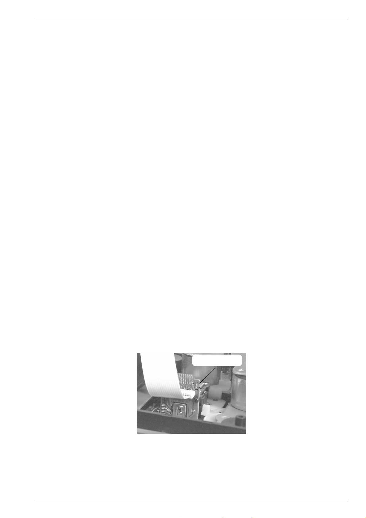
Servicehinweis
Bei Ausbau des CD-Laufwerks muß vor Abziehen der Steckverbindungen eine Schutzlötstelle auf der Leiterplatte der Lasereinheit
angebracht werden, um eine Zerstörung der
Laserdiode durch statische Aufladung zu
vermeiden.
Beim Einbau einer neuen Lasereinheit muß
nach Einstecken der Steckverbindungen die
werkseitig angebrachte Schutzlötstelle entfernt werden.
GRUNDIG Service 1 - 3
Schutzlötstelle
protective soldered joint
Service Hint
Before detaching the plug-in connections
when removing the CD drive mechanism a
protective solder joint must be provided on
the circuit board of the laser pick-up to avoid
the laser diode being destroyed by static
charges.
When fitting a new laser pick-up the protective solder joint provided in the factory must
be removed before inserting the plug-in connections.
Page 4
Allgemeiner Teil / General Section KM 12
Ausbauhinweise
Die Teilebezeichnungen (wie z.B. M7A1) im Text und bei den Abbildungen sind mit den Positionsnummern in den Ersatzteillisten und
Explosionszeichnugen übereinstimmend.
Anhand der Indexnummer (…1) kann man erkennen, in welcher
Explosionszeichnung das Teil abgebildet ist.
Die Explosionszeichnungen sind in dem Kapitel „Ersatzteillisten und
Explosionszeichnungen“ zu finden.
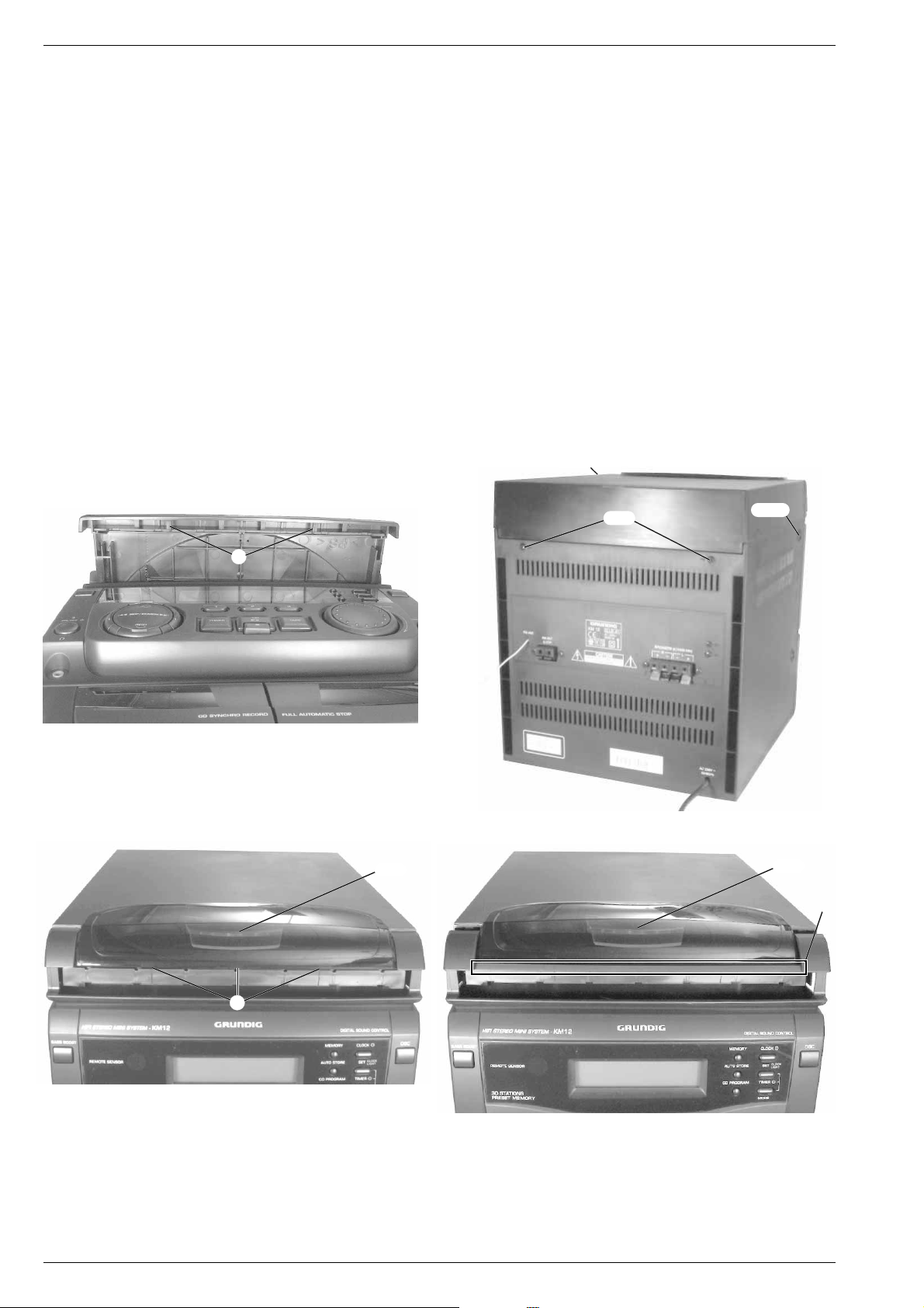
1. Gehäuseoberteil M351 mit CD-Teil ausbauen
- CD-Schublade M12 herausziehen, 2 Rastnasen A ausrasten und
Schubladenblende M101 nach oben abnehmen (Fig. 1).
- 2 Schrauben M7A1 und 2 Schrauben M67A1 herausschrauben
(Fig. 2).
- Gehäuseoberteil M351 mit CD-Teil hinten 2-3cm anheben.
- Die 3 kleinen Rastnasen B an der Fensterunterkante ausrasten
(Fig. 3), das Fenster M361 mit dem Gehäuseoberteil M351 soweit
nach oben drücken bis man das Fenster M361 über den Steg X der
Frontblende M81 nach hinten schieben kann (Fig. 4).
- Gehäuseoberteil M351 mit dem CD-Teil nach oben abnehmen und
bei Bedarf die beiden Steckverbindungen lösen.
Achtung:
M361 eingebaut werden. Das Fenster M361 muß zuvor ausgebaut
werden, wie unter Punkt 2. beschrieben.
Das Gehäuseoberteil M351 kann nur ohne das Fenster
Disassembly Instructions
The designations of parts (e.g. M7A1) in the text and figures are
identical with the position numbers in the spare parts lists and exploded
views.
From the index number (…1) it can be seen in which exploded view this
part is to be found.
The exploded views are shown in chapter „Spare Parts Lists and
Exploded Views“.
1. Removing the Cabinet Top M351 with CD Unit
- Draw out the CD tray M12, disengage 2 catches A and pull out the
tray cover M101 towards the top (Fig. 1).
- Undo 2 screws M7A1 and 2 screws M67A1 (Fig. 2).
- Lift the cabinet top M351 with the CD unit on the rear side by 2-3cm.
- Disengage the 3 small catches B at the bottom edge of the window
(Fig. 3), press the window M361 with the cabinet top M351 upwards
until it is possible to move the window M361 over rail X of the front
cover M81 to the rear (Fig. 4).
- Lift the cabinet top M351 with the CD unit to remove it. If necessary
loosen the connectors.
Attention:
window M361. For this, remove the window M361 first as described
under point 2.
The cabinet top M351 can only be fitted without the
1
M67A
1
M7A
1
M67A
Fig. 1
A
B
M36
Fig. 2
1
1
M36
X
Fig. 3
Fig. 4
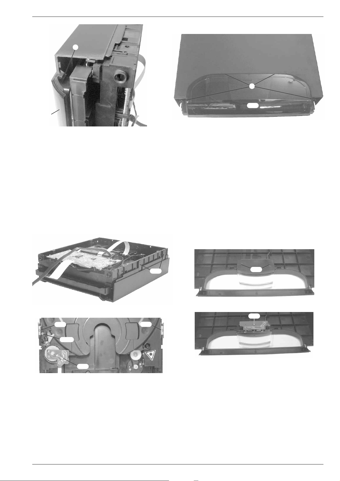
2. Fenster M361 ausbauen
- Gehäuseoberteil M351 mit CD-Teil ausbauen (Punkt 1).
- Die 4 Rastnasen C ausrasten und das Fenster M361 abnehmen
(Fig. 5, 6).
- Das Fenster M361 darf nur bei eingebautem Gehäuseoberteil M35
2. Removing Window M36
- Remove cabinet top M351 with CD unit (point 1).
- Disengage 4 catches C and take out window M361 (Fig. 5, 6).
1
- The window M361 is allowed to be inserted onlyafter having fitted the
cabinet top M351.
1
eingesetzt werden.
1 - 4 GRUNDIG Service
Page 5
M36
1
Fig. 5
C
Fig. 6
C
M36
Allgemeiner Teil / General SectionKM 12
1
3. CD-Teil ausbauen
- Gehäuseoberteil M351 mit CD-Teil ausbauen (Punkt 1).
- 4 Schrauben M301 herausschrauben (Fig. 7).
- Bei Bedarf die Leitung für die CD-Beleuchtungsplatte M33A1 lösen
und das CD-Teil aus dem Gehäuseoberteil herausnehmen.
4. CD-Beleuchtungsplatte M33A1 ausbauen
- CD-Teil ausbauen (Punkt 3).
- 2 Schrauben M301 herausschrauben und die Abdeckung M31
abnehmen (Fig. 8).
- Schraube M321 der CD-Beleuchtungsplatte M33A1 herausschrauben (Fig. 9).
- Die Leiterplatte M33A1 und der Lichtleiter M341 können aus dem
Gehäuseoberteil M351 herausgenommen werden (Fig. 9).
1
M30
Fig. 7
M38
2
M38
2
3. Removing the CD Unit
- Remove cabinet top M351 with the CD unit (point 1).
- Undo 4 screws M301 (Fig. 7).
- If necessary disconnect the lead for the CD-LED circuit board M33A
1
and take the CD unit out of the cabinet top.
4. Removing the CD-LED Circuit Board M33A
1
- Remove the CD unit (point 3).
- Undo 2 screws M301 and take cover M311 off (Fig. 8).
1
- Undo screw M321 on the CD-LED circuit board M33A1 (Fig. 9).
- Circuit board M33A1 and fiber-optic light guide M341 can be taken out
from the cabinet top M351 (Fig. 9).
1
M30
Fig. 8
1
M32
2
M31B
Fig. 9
2
M32
Fig. 10
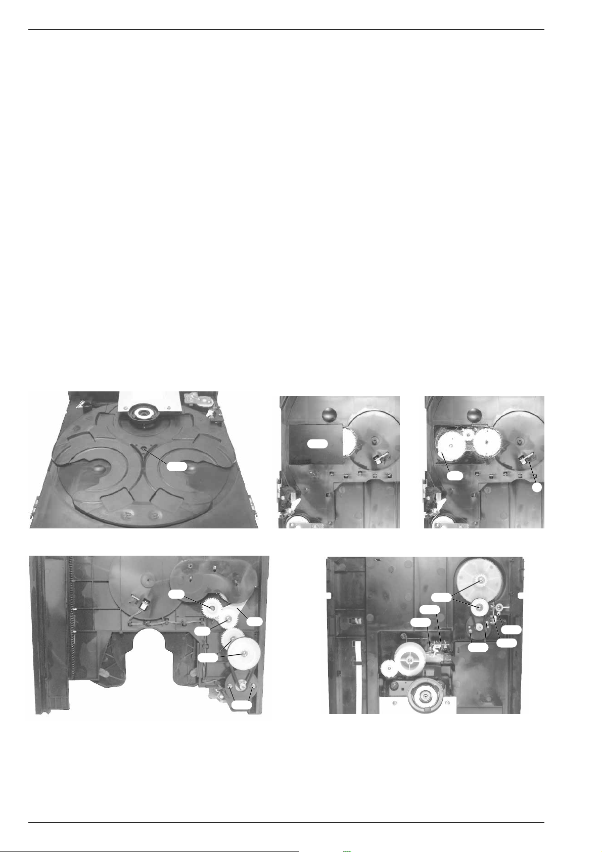
5. CD-Teil zerlegen
- CD-Teil ausbauen (Punkt 3).
5.1 CD-Schublade ausbauen
- Bei Bedarf die Flachbandleitung zur Drehtellermotorplatte M32
lösen (Fig. 10).
- 2 Schrauben M382 (Fig. 10) herausschrauben und die
Schubladenführungen M372 abnehmen.
2
5. Dismantling the CD Unit
- Remove the CD unit (point 3).
5.1 Removing the CD Tray
- If necessary disconnect the ribbon cable to the disc turntable motor
M322 (Fig. 10).
- Undo 2 screws M382 (Fig. 10) and take the tray guides M372 off.
- Pull the tray out.
- Die Schublade herausziehen.
GRUNDIG Service 1 - 5
Page 6
Allgemeiner Teil / General Section KM 12
5.2 Move/Stop-Platte M282 ausbauen
- Schraube M31B2 (Fig. 10) herausschrauben und die Abdeckung
M31A2 abnehmen.
- Die Feder M302 aushängen, den Hebel M272 und die Leiterplatte
M282 herausnehmen.
5.3 CD-Tellermechanik ausbauen
- CD-Schublade ausbauen (Punkt 5.1).
- Schraube M252 (Fig. 11) herausschrauben und den Teller M24
abnehmen.
- Die aufgeklebte Zahnradabdeckung M212 (Fig. 12) vorsichtig entfernen.
- Das kleine Zahnrad M182 und das Doppelzahnrad M202 kann
einfach nach oben herausgenommen werden.
- Das sperrbare Zahnrad M172 kann nur herausgenommen werden
wenn der Verriegelungshebel M82 (Fig. 13) zurückgeschoben
wird.
- Schraube M92 (Fig. 14) herausschrauben, das Zahnrad M102 und
der Verriegelunshebel M82 (Fig. 13, 14) können herausgenommen werden.
- Die Sicherungscheibe M32 (Fig. 14) lösen und beim Herausnehmen des Zahnrads M62 auf die darunterbefindliche Feder M5
achten, diese kann wegspringen.
- Die Riemenscheibe M132 und das Zahnrad M152 können durch
Herausschrauben der jeweilgen Schraube M122 (Fig. 14) herausgenommen werden.
- 2 Schrauben M162 (Fig. 14) herausschrauben und Drehtellermotor E12 herausnehmen.
5.4 Disc Counter-Platte M232 ausbauen
- Schraube M252 (Fig. 11) herausschrauben und den Teller M24
abnehmen.
- Die Klebestellen am Schalter lösen, die Rastnase D (Fig. 13)
ausrasten und Leiterplatte M232 herausnehmen.
5.2 Removing the Move/Stop Circuit Board M28
2
- Undo screw M31B2 (Fig. 10) and take the cover M31A2 off.
- Detach spring M302, remove lever M272 and circuit board M282.
5.3 Removing the CD Turntable Mechanics
2
- Remove the CD tray (point 5.1).
- Undo screw M252 (Fig. 11) and take turntable M242 out.
- Remove the glued on gearwheel cover M212 (Fig. 12) carefully.
- The small gearwheel M182 and the gear pair M202 can simply be
lifted and removed.
- The lockable gearwheel M172 can only be taken out after having
pushed back the locking lever M82 (Fig. 13).
- Undo screw M92 (Fig. 14), gearwheel M102 and locking lever M8
2
(Fig. 13, 14) can be taken out.
- Loosen the securing washer M32 (Fig. 14). When taking out the
gearwheel M62 take care of spring M52 below it. It may come off.
- Pulley M132 and gearwheel M152 can be taken out by undoing the
corresponding screw M122 (Fig. 14).
2
2
- Undo 2 screws M162 (Fig. 14) and remove the turntable motor E12.
5.4 Removing the Disc Counter Circuit Board M23
2
- Undo screw M252 (Fig. 11) and take the turntable M242 off.
- Loosen the glued joints on the switch, disengage catch D (Fig. 13)
and remove circuit board M232.
2
M21
2
M25
Fig. 11 Fig. 12 Fig. 13
2
Fig. 14
M3
M9
M12
2
M16
M8
2
2
2
Fig. 15
M38
M55
2
M41
2
2
M8
2
D
2
M38
2
M51
2
M16
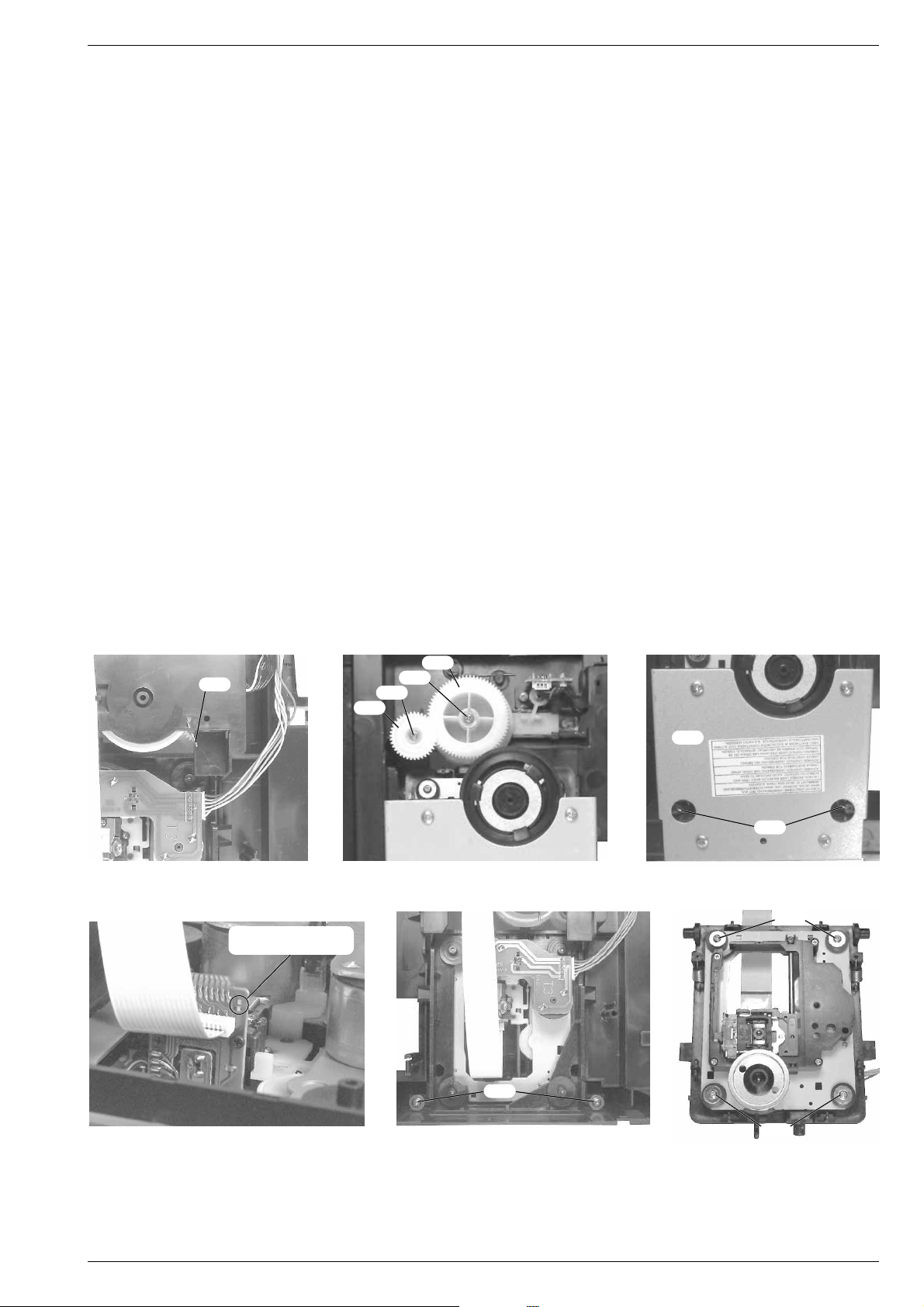
5.5 CD Deck Up/Down-Platte M552 ausbauen
- CD-Schublade ausbauen (Punkt 5.1).
- Schraube M382 (Fig. 15) herausschrauben, bei Bedarf die Leitung
zur CD-Decoder-Platte M332 lösen und die CD Deck Up/DownPlatte M552 (Fig. 15) herausnehmen.
5.5 Removing the CD Deck Up/Down Circuit Board M55
- Remove the CD tray (point 5.1).
- Undo screw M382 (Fig. 15), disconnect the lead to the CD decoder
circuit board M332 if necessary, and remove the CD Deck Up/
Down circuit board M552 (Fig. 15).
2
1 - 6 GRUNDIG Service
Page 7
Allgemeiner Teil / General SectionKM 12
5.6 CD Deck Open/Close-Platte M512 ausbauen
- CD-Schublade ausbauen (Punkt 5.1).
- Schraube M382 herausschrauben und die Leiterplatte M512 herausnehmen (Fig. 15).
5.7 CD-Schubladenantrieb ausbauen
- CD-Schublade ausbauen (Punkt 5.1).
- Die Riemenscheibe M472 und das Zahnrad M502 kann durch
Herausschrauben der jeweilgen Schraube M412 (Fig. 15) herausgenommen werden.
- CD-Decoder-Platte ausbauen (Punkt 5.10).
- 2 Schrauben M162 (Fig. 15) herausschrauben und Schubladenmotor E12 nach unten herausnehmen.
5.8 CD-Laufwerklift ausbauen
- Die Feder M532 in die Service-Stellung bringen wie in Fig. 16
abgebildet.
- Die Schrauben M292, M412 herausschrauben, das Zahnrad M56
und das Kurvenrad M582 abnehmen (Fig. 17).
5.9 CD-Laufwerk ausbauen
*Achtung:
Bei Ausbau des CD-Laufwerks muß vor Abziehen der
Steckverbindungen eine Schutzlötstelle auf der Leiterplatte
(Fig. 19) der Lasereinheit angebracht werden, um eine Zerstörung
der Laserdiode durch statische Aufladung zu vermeiden.
Beim Einbau einer neuen Lasereinheit muß nach Einstecken der
Steckverbindungen die werkseitig angebrachte Schutzlötstelle
entfernt werden.
- Das CD-Laufwerk in die oberste Liftstellung bringen.
- Die beiden Federn M422 (Fig. 18) aushängen.
Das Ausbauen der Metallplatte M592 erleichtert das Einhängen
der Federn M422 (Fig. 18).
- Bei Bedarf die Verbindungsleitungen lösen*.
- Die beiden Schrauben M412 (Fig. 20) auf der Unterseite herausschrauben und das CD-Laufwerk mit dem Laufwerkrahmen von
unten herausnehmen.
- 4 Schrauben M452 (Fig. 21) herausschrauben und das CD-Laufwerk aus dem Laufwerkrahmen herausnehmen.
5.6 Removing the CD Deck Open/Close Circuit Board M51
2
- Remove the CD tray (point 5.1).
- Undo screw M382 and remove circuit board M512 (Fig. 15).
5.7 Removing the CD Tray Gear
- Remove the CD tray (point 5.1).
- Pulley M472 and gearwheel M502 can be taken out by undoing the
corresponding screw M412 (Fig. 15).
- Remove the CD-Decoder circuit board (point 5.10).
- Undo 2 screws M162 (Fig. 15) and remove the tray motor E1
2
towards the bottom.
5.8 Removing the Lift of the CD Drive Mechanism
- Set spring M532 in service position as shown in Fig. 16.
2
- Undo screws M292, M412 , take out gearwheel M562 and cam M58
(Fig. 17).
2
5.9 Removing the CD Drive Mechanism
*Warning:
Before detaching the plug-in connections when
removing the CD drive mechanism a protective solder joint must be
provided on the circuit board (Fig. 19) of the laser pick-up to avoid
the laser diode being destroyed by static charges.
When fitting a new laser pick-up the protective solder joint provided
in the factory must be removed before inserting the plug-in
connections.
- Move the CD drive mechanism to its upper limit lift position.
- Detach the two springs M422 (Fig. 18).
The springs M422 can be attached easier when removing the metal
plate M592 (Fig. 18).
- Loosen the conncting leads if necessary*.
- Undo the two screws M412 (Fig. 20) on the bottom and remove the
CD drive mechanism together with the frame from the bottom.
- Undo the 4 screws M452 (Fig. 21) and remove the CD drive
mechanism from its frame.
Fig. 16
2
M53
Schutzlötstelle
protective soldered joint
M56
Fig. 17
M29
2
M41
2
M58
2
2
2
M59
2
M42
Fig. 18
2
M45
2
M41
2
Fig. 19
5.10 CD-Decoder-Platte M332 ausbauen
- 2 Schrauben M342 herausschrauben (Fig. 22), die Schubladenmotorkontakte E12 ablöten.
- Die Leiterplatte M332 herausnehmen und bei Bedarf die Steckverbindungen lösen.
GRUNDIG Service 1 - 7
Fig. 20
Fig. 21
5.10 Removing the CD-Decoder Circuit Board M33
- Undo 2 screws M342 (Fig. 22), unsolder the tray motor contacts
E12.
- Remove the circuit board M332 and detach the plug-in
connections if necessary.
M45
2
Page 8

Allgemeiner Teil / General Section KM 12
2
M34
1
M7
M7
1
M69
1
M67
1
Fig. 22
1
M7
Fig. 23
6. Hauptplatte M641 ausbauen
- Gehäuseoberteil M351 mit CD-Teil ausbauen (Punkt 1).
- Bei Bedarf die Seckverbindungen lösen.
- 4 Schrauben M71 (Fig. 24) auf der Geräterückseite und 3 Schrauben
M71 (Fig. 23) auf der Geräteunterseite herausschrauben.
- 2 Schrauben M691 und 2 Schrauben M671 herausschrauben
(Fig. 24).
- Schraube M131 (Fig. 25) herausschrauben und Hauptplatte M64
mit der kompletten Gerätefront nach vorne herausziehen.
- Schraube M131, 2 Schrauben M561 herausschrauben (Fig. 26).
- Die über die Steckverbindung CN301 (Fig. 26) mit der Frontplatte
M251 verbundene Hauptplatte M641 abziehen.
1
M13
CN301
1
M13
1
M56
1
M56
Fig. 24
6. Removing the Main Circuit Board M64
1
- Remove the cabinet top M351 with CD unit (point 1).
- Detach the plug-in connections if necessary.
- Undo the 4 screws M71 (Fig. 24) on the rear and 3 screws M7
1
(Fig. 23) on the bottom of the mini system.
- Undo 2 screws M691 and 2 screws M671 (Fig. 24).
1
- Undo screw M131 (Fig. 25) and pull out the main circuit board M64
together with the complete front of the mini system towards the front.
1
- Undo screw M131, 2 screws M561 (Fig. 26).
- Pull off the main circuit board M641 which is plugged into the front
circuit board M251 by CN301(Fig. 26).
1
M13
1
M13
Fig. 25 Fig. 26
7. Frontplatte M251 ausbauen
- Hauptplatte M641 ausbauen (Punkt 6).
- Lautstärkeknopf von vorne abziehen.
- 12 Schrauben M131 (Fig. 27) herausschrauben und die Frontplatte
M251 abnehmen.
8. Cassettentürbremse M91 ausbauen
- Gehäuseoberteil M351 mit CD-Teil ausbauen (Punkt 1).
- Bei Bedarf die Seckverbindungen lösen.
- 4 Schrauben M71 (Fig. 24) auf der Geräterückseite und 3 Schrauben
M71 (Fig. 23) auf der Geräteunterseite herausschrauben.
- 2 Schrauben M691 und 2 Schrauben M671 herausschrauben
(Fig. 24).
- Schraube M131 (Fig. 25) herausschrauben und Hauptplatte M64
mit der kompletten Gerätefront nach vorne herausziehen.
- Die Rastnase E (Fig. 28) ausrasten und die Cassettentürbremse
7. Removing the Front Circuit Board M25
- Remove the main circuit board M641 (point 6).
- Pull off the volume control knob from the front.
- Undo 12 screws M131 (Fig. 27) and remove the front circuit board
M251.
8. Removing the Brake of the Cassette Door M9
- Remove the cabinet top M351 with the CD unit (point 1).
- Detach the plug-in connections if necessary.
- Undo the 4 screws M71 (Fig. 24) on the rear and 3 screws M7
(Fig. 23) on the bottom of the mini system.
- Undo 2 screws M691 and 2 screws M671 (Fig. 24).
1
- Undo screw M131 (Fig. 25) and pull out the main circuit board M64
together with the complete front of the mini system towards the front.
- Disengage catch E (Fig. 28) and remove brake M91 of the cassette
door.
Fig. 27
1
1
M91 herausnehmen.
1 - 8 GRUNDIG Service
1
1
Page 9

E
Allgemeiner Teil / General SectionKM 12
1
M13
Fig. 28
Fig. 29
9. Laufwerk ausbauen
- Hauptplatte M641 ausbauen (Punkt 6).
- Die beiden Cassettentüren öffnen.
- 6 Schrauben M131 (Fig. 29) herausschrauben und das Laufwerk
abnehmen.
10. Laufwerk zerlegen
- Laufwerk ausbauen (Punkt 9).
10.1 Motor M49.100 ausbauen
- Flachbandleitung zum Motor ablöten.
- Die Antriebsriehmen M49.300 und M49.400 aushängen.
- Die 4 Schrauben F (Fig. 29), die 4 Schrauben G (Fig. 30)
herausschrauben und den Verbindungsrahmen H vorsichtig
aushängen.
Achtung:
Beim Aus- und Einbau des Verbindungsrahmens H
auf den Pausenverriegelungshebel I achten (Fig. 30)!
- 3 Schrauben J herausschrauben und den Motor abnehmen
(Fig. 31).
1
M13
M13
F
9. Removing the Drive Mechanism
- Remove the main circuit board M641 (point 6).
- Open the two cassette doors.
- Undo 6 screws M131 (Fig. 29) and take the drive mechanism off.
10. Disassembling the Drive Mechanism
- Dismantle the drive mechanism (point 9).
10.1 Removing the Motor M49.100
- Unsolder the ribbon cable to the motor.
- Detach the drive belts M49.300 and M49.400.
- Undo 4 screws F (Fig. 29), 4 screws G (Fig. 30) and disengage
the connecting frame H carefully.
Warning:
take care of the pause locking lever I (Fig. 30)!
- Undo 3 screws J and take the motor off (Fig. 31).
When removing and refitting the connecting frame H
1
H
H
J
G
I
G
Fig. 30
Fig. 31
10.2 Laufwerktasten M381 - M481 ausbauen
- Jeweils die beiden Rastnasen K (Fig. 32) auf den Tastenträgern
ausrasten und die auszuwechselnden Tasten abnehmen.
10.3 Laufwerktastenrahmen M511, M521 ausbauen
- Laufwerktasten M381 - M481 ausbauen (Punkt 10.1).
- Die 2 Schrauben L (Fig. 32) des auszubauenden Rahmens
herausschrauben.
- Den Tastenrahmen aushängen, indem man den Rahmen auf der
linken Seite nach unten schiebt und leicht anhebt, danach den
Rahmen vorsichtig nach rechts schieben, bis der Laufwerktastenrahmen abgenommen werden kann.
KLL
KK
Fig. 32
10.2 Removing the Tape Deck Operating Buttons M381 - M48
- Disengage the two catches K (Fig. 32) on each of the button
carriers and remove the buttons which are to be replaced.
10.3 Removing the Frame of the Tape Deck Operating Buttons
M511, M52
1
- Remove the tape deck operating buttons M381 - M48
(point 10.1).
- Undo the 2 screws L (Fig. 32) of the frame which is to be
removed.
- Push the frame of the buttons down on the left side and raise it
slightly to detach it, then push it carefully to the right until it can be
taken off.
1
1
GRUNDIG Service 1 - 9
Page 10

Abgleichvorschriften / Adjustment Procedures KM 12
Abgleichvorschriften
D
1. Tuner
Meßgeräte: Meßsender, Stereocoder, Oszilloskop, DC-Voltmeter, NF-Voltmeter
Abgleich Vorbereitung Abgleichvorgang
1. MW-ZF
2. MW-Oszillator
3. MW-Vorkreis
4. FM-Oszillator
5. FM-Vorkreis
6. Stereo
MW; am Gerät 522kHz einstellen.
Meßsender 450kHz an Antennenbuchse.
Ua nur so groß, daß das Signal gerade erkennbar ist;
f
= 400Hz; m = 30%;
mod
NF-Voltmeter an Meßpunkt TP1(IF).
MW;
DC-Voltmeter an Meßpunkt TP1(VT).
MW;
Meßsender an Antennenbuchse.
Ua nur so groß, daß das Signal gerade erkennbar ist;
f
= 400Hz; m = 30%;
mod
NF-Voltmeter an Lautsprecherausgang.
FM;
DC-Voltmeter an Meßpunkt TP1(VT).
FM;
Meßsender an Antennenanschluß.
Ua nur so groß, daß das Signal gerade erkennbar ist;
f
= 1kHz; ∆f = 22,5kHz;
mod
NF-Voltmeter an Lautsprecherausgang.
FM;
Stereocoder 98MHz an Antennenanschluß.
Ua = 26dBµV; f
= 19kHz;
mod
2. Cassettenteil
Meßgeräte: NF-Voltmeter, Frequenzzähler, Testkassette 449 Sach-Nr.: 35079-019.00
Mit T102 auf NF-Maximum abgleichen.
Mit L105 bei 522kHz auf 1,2V ±0,05V.
Kontrolle bei 1629kHz 8,0V ±1,0V.
Wechselweise mit L104 bei 603kHz und mit TC102 bei
1404kHz auf NF-Maximum abgleichen.
Mit L103 bei 87,5MHz auf 1,2V abgleichen.
Kontrolle bei 108MHz 8,0V ±1,0V.
Wechselweise mit L102 bei 90,0MHz und mit TC101 bei
106,0MHz auf NF-Maximum abgleichen.
Mit SFR101 die Stereo-Schwelle (Ua = 26dBµV) so
abgleichen, daß die Stereo-Anzeige im Display noch
aufleuchtet.
Abgleich Vorbereitung Abgleichvorgang
1. Azimut
2. Geschwindigkeit
Die Einstellschrauben sind durch Aussparungen unter
den Cassettenklappen zugänglich.
Testkassette 449 Pegeltonteil 10kHz wiedergeben
NF-Voltmeter an NF-Ausgang.
Tape, Fe.
Testkassette 449 Pegeltonteil 3150Hz wiedergeben
Frequenzzähler an NF-Ausgang
Mit Schraube A auf NF-Maximum
abgleichen.
Mit SFR201 auf 3110Hz - 3240Hz einstellen.
3. CD-Teil
Meßgeräte: DC-Voltmeter, Oszilloskop, Test-CD Sachnr.: 72008-376.00
Abgleich Vorbereitung Abgleichvorgang
1. RF Gain
2. E-F-Balance
CD-Spieler auf STOP.
DC-Voltmeter an Meßpunkt CN12.
Auf der Front-Platte, wie auf Seite 3 - 12 abgebildet, mit
einer Diode (1N4148) die Pins der Steckverbindung
CN601 Pin 19 (Anode) und Pin 8 (Katode) verbinden
und die Tasten „CD CHECK“ und „REPEAT“ anlöten.
Oszilloskop an Meßpunkt CN02 (+/-).
Test-CD einlegen und wiedergeben.
Die eingebauten Tasten „CD CHECK“ und „REPEAT“
gleichzeitig drücken und VR02 abgleichen.
Nach Beendigung des Abgleichvorgangs, die Taste
„STOP“ drücken und die Diode entfernen.
Mit VR01 auf 0V ±20mV abgleichen.
Mit VR02 die Amplitude des Signals symmetrisch zur
Null-Linie abgleichen (A=B).
A
2 - 1 GRUNDIG Service
Page 11

Abgleichvorschriften / Adjustment ProceduresKM 12
Adjustment Procedures
GB
1. Tuner
Test equipment: Test Generator, Stereo Coder, Oscilloscope, DC Voltmeter, AF Voltmeter
Adjustment Preperation Adjustment Procedure
1. AM IF
2. AM Oscillator
3. AM Aerial
Bandpass
4. FM Oscillator
5. FM Aerial
Bandpass
6. Stereo
MW; set the tuner to 522kHz.
Test generator 450kHz at aerial input.
Ua as low as possible; f
AF voltmeter at test point TP1(IF).
MW;
DC voltmeter at test point TP1(VT).
MW;
Test generator at aerial input.
Ua as low as possible; f
AF voltmeter at loudspeaker output.
FM;
DC voltmeter at test point TP1(VT).
FM;
Test generator at aerial input.
Ua as low as possible; f
AF voltmeter at loudspeaker output.
FM;
Stereo coder 98MHz at aerial input.
Ua = 26dBµV; f
= 19kHz;
mod
= 400Hz; m = 30%;
mod
= 400Hz; m = 30%;
mod
= 400Hz; ∆f = 22.5kHz;
mod
Adjust T102 for AF maximum.
Adjust L105 at 522kHz for 1.2V ±0.05V.
Check at 1629kHz 8.0V ±1.0V.
Adjust alternately L104 at 603kHz and TC102 at
1404kHz for AF maximum.
Adjust L103 at 87.5MHz for 1.2V.
Check at 108MHz 8.0V ±1.0V.
Adjust alternately L102 at 90.0MHz and TC101 at
106.0MHz for AF maximum.
With SFR101 adjust the stereo threshold (Ua = 26dBµV)
so that the stereo indication still illuminates on the
display.
2. Cassette Part
Test equipment: AF Voltmeter, Frequency Counter, Test Cassette 449 Part No.: 35079-019.00
Adjustment Preperation Adjustment Procedure
1. Azimuth
2. Tape Speed
Access to the screws is gained through holes below the
cassette flaps.
Play Test Cassette 449, 10kHz part.
AF voltmeter at AF output.
Tape, Fe.
Play Test Cassette 449, 3150Hz part.
Frequency counter at AF output.
Adjust screw A for AF maximum.
Adjust SFR201 for 3110Hz - 3240Hz.
3. CD Part
Test equipment: DC Voltmeter, Oscilloscope, Test CD Part No.: 72008-376.00
Adjustment Preperation Adjustment Procedure
1. RF Gain
2. E-F-Balance
Set CD player to STOP.
DC voltmeter at test point CN12.
Connect a diode (1N4148) between pin 19 (anode) and
pin 8 (cathode) of connector CN601 on the Front Panel
as shown on page 3 - 12, and solder the buttons
„CD CHECK“ and „REPEAT“ on to the panel.
Oscilloscope to test point CN02 (+/-).
Load the test CD and play.
Depress the soldered buttons „CD CHECK“ and
„REPEAT“ simultaneously and adjust VR02.
On completion of this adjustment press the „STOP“
button and remove the diode.
Adjust VR01 for 0V ±20mV.
Set VR02 so that the signal amplitude is symmetrical
to the datum line (A=B).
A
GRUNDIG Service 2 - 2
Page 12

Abgleichvorschriften / Adjustment Procedures KM 12
Abgleichlagepläne / Alignment Layouts
1. Tuner
2. Cassette
SFR201
SPEAKER JACK
3. CD
SFR101
CN12
TP1
VT IF
T102
L105
CN02
VR01
TC102
L103
L104
L102
TC101
B_
B
VR02
8
19
CN09
2 - 3 GRUNDIG Service
121
Page 13

GRUNDIG Service 3 - 1
Blockschaltplan – KM 12 / Block Diagram – KM 12
Platinenabbildungen und Schaltpläne / Layout of PCBs and Circuit Diagrams
Platinenabbildungen und Schaltpläne / Layout of PCBs and Circuit DiagramsKM 12
Page 14

3 - 2 GRUNDIG Service
Platinenabbildungen und Schaltpläne / Layout of PCBs and Circuit Diagrams KM 12
Blockschaltplan – CD-Teil / Block Diagram – CD Part
Page 15

Verdrahtungsplan / Wiring Diagram
Platinenabbildungen und Schaltpläne / Layout of PCBs and Circuit Diagrams Platinenabbildungen und Schaltpläne / Layout of PCBs and Circuit DiagramsKM 12 KM 12
GRUNDIG Service GRUNDIG Service
3 - 3 3 - 4
Page 16

Platinenabbildungen und Schaltpläne / Layout of PCBs and Circuit Diagrams Platinenabbildungen und Schaltpläne / Layout of PCBs and Circuit Diagrams KM 12KM 12
Schaltplan / Circuit Diagram: -LED-Platte / LED Board -CD-Decoder-Platte / CD Decoder Board
-Motorplatte / Motor Board -Schalterplatten A - D / Switch Boards A - D
TO MOTOR PCB
CN06-
TO SWITCH D PCB
CN05-
TO FRONT PCB
CN601
PAGE 3 - 10
º
º
º
º
º
º
º
º
TEST POINT TEST POINT
TO MAIN PCB
CN302
PAGE 3 - 14
TO CD DECODER PCB CN05
ººº
º
TO CD DECODER PCB CN06
º
º
º
3 - 5 3 - 6
GRUNDIG Service GRUNDIG Service
Page 17

Platinenabbildungen und Schaltpläne / Layout of PCBs and Circuit Diagrams Platinenabbildungen und Schaltpläne / Layout of PCBs and Circuit Diagrams KM 12KM 12
Schaltplan / Circuit Diagram: -Front-Platte / Front Board
-Fernbedienplatte / Remote Receiver Board
TO MAIN PCB
CN301
PAGE 3 - 14
TO CD DECODER PCB
CN09
PAGE 3 - 6
3 - 9 3 - 10
GRUNDIG Service GRUNDIG Service
Page 18

Platinenabbildungen und Schaltpläne / Layout of PCBs and Circuit Diagrams Platinenabbildungen und Schaltpläne / Layout of PCBs and Circuit Diagrams KM 12KM 12
Schaltplan / Circuit Diagram: -Aufnahmeschalterplatte / Record Switch Board -Hauptplatte / Main Board
-Trafoplatte / Transformer Primary Board
TO FRONT PCB
CN301
PAGE 3 - 9
TO MAIN PCB
CN401
TO CD DECODER PCB
CN08
PAGE 3 - 6
º
º
º
º
º
º
º
º
3 - 13 3 - 14
GRUNDIG Service GRUNDIG Service
SWITCHES
TO CASS. DECK
MOTOR
TO CASS. DECK
CN401-
TO TRANS. PRIMARY PCB
Page 19

IC-Block-Diagramme / IC Block Diagrams
RF-IN GND IF OUT VccRF-OUT OSCOSC
RF MIX REG OSC
BUFFER
Vref
1 2 3 4 5 6 7 8 9
LA 1186
GND
Platinenabbildungen und Schaltpläne / Layout of PCBs and Circuit Diagrams Platinenabbildungen und Schaltpläne / Layout of PCBs and Circuit DiagramsKM 12 KM 12
IC01 CXA1782BG
EMPHI
LRCK1
PGMDI
BCK1
MUTE
BCK
BCMD
LRCK
WDCK
C2PO
RFCK
MNT0
MNT1
MNT3
WFCK
EMPH
GFS
XUGF
GTOP
IC03 BA5941FPIC04 CXA2508Q
SHIFT
–
SHIFT
LEVEL
–
+
20K
20K
20K
20K
–
+
+
–
–
+
+
–
Vcc
MUTE
10K
10K
14
13
12
11
10
9
8
7
6
5
4
3
2
XTAI
XTAO
ZEROL
73 74 66 65
63
43
45
47
6
46
44
42
41
54
52
58
57
56
64
62
51
49
48
error
corrector
Interface
EFM
demodulator
D/A
16K RAM
SUB code
Processor
Digital Filter
1bit DAC
digital
OUT
ZEROR
69
NLPWM
70
+
digital
CLV
CPU
Interface
78
77
61
55
27
26
25
24
5
4
3
2
1
22
19
11
10
9
7
LPWM
RPWM
NRPWM
DOUT
XROF
LOCK
MDS
MDP
MON
SQCK
SQSO
EXCK
SBSO
SCOR
XLON
SPOB~D
CLOK
XLAT
DATA
SENS
15
16
17
18
19
20
21
22
23
24
25
17
clock
generator
asymmetry
corrector
digital
PLL
Servo auto
sequencer
CLKO
16
XLTO
15
DATO
26
27
20K
–
+
SHIFT
LEVEL
–
LEVEL
+–+
+
–
20K
20K
–
+
SHIFT
+
–
Vcc
µC
19.9K 19.9K
+
–
10K
10K
LEVEL
20K
–
+
19.9K 19.9K
IC101 LA1186N
IC02 TC9173P
15
STB
16
DD
V
1
GND
I/O-1
2
(OP-1)
CK SOSI
SERIAL I/O
CONTROL CIRCUIT
CY
LATCH
I/O-10
(OP-10)
11121314
LATCH
SYC
Vcc
1
59
60RF36
FSTT
C4M
38
39
40
37
50
29
30
31
34
23
13
14
ASYI
ASYO
XPCK
FILI
PCO
FILO
BIAS
ASYE
FOK
SEIN
CLTV
CNIN
IC103 LC7218
28
6
LC7218
PD1
XIN
1
IC102 LA1831
I/O-9
10
(OP-9)
I/O-8
9
(OP-8)
I/O-7
8
(OP-7)
I/O-6
7
(OP-6)
XOUT
FMIN
AMIN
CE
CL
24
19
18
2
3
DI
4
REFERENCE
DIVIDER
1
SWALLOW COUNTER
2
1/16, 1/17 4BIT
12 BIT PROGRAMMABLE
SHIFT REGISTER
LATCH
DIVIDER
PHASE DETECTOR
CHARGE PUMP
UNIVERSAL
COUNTER
21
22
PD2
16
HCTR
15
LCTR
20
DD
V
23
Vss
DO
Note: The name in ( ) is the terminal name for TC9174P/F.
GRUNDIG Service GRUNDIG Service
3456
I/O-2
(OP-2)
I/O-3
(OP-3)
I/O-4
(OP-4)
I/O-5
(OP-5)
DRIVER
3 - 19 3 - 20
5
9
OUT0
121110
13 14 17 7 8
OUT3OUT2OUT1
OUT4 OUT5 OUT6 IN0 IN1
Page 20

Platinenabbildungen und Schaltpläne / Layout of PCBs and Circuit Diagrams Platinenabbildungen und Schaltpläne / Layout of PCBs and Circuit Diagrams KM 12KM 12
IC201 TA8189N IC303 TA8216H IC602 TC74HC237AP
ch2/B
ch2/A
ch1/A
ch1/B
TA 8189 N
23
24
*
1
2
Metal
NF
Out
–
ch 2
+
+
ch 1
–
345678910
NF Metal
Out
T ape A
Pre
Tape B
Out NF
A / B
1
1
ref
ref
I
V
MIX
Pre
Out
Out
GND 1
M / N
M/N
Rec
OutCGVCC
1516171819202122
–
ch 2
Rec
Out
ch 1
+
ALC
+
–
NF
2
ref
V
14
13
12
11
Rec IN
ALC
GND
Rec IN
SELECT
A
B
C
G1
Y0
Y1
Y2
Y3
Y4
Y5
Y6
Y7
DATA
OUTPUTS
IC301 LC75392
L1
(R1)
L2
(R2)
L3
(R3)
L4
(R4)
Vref
ENABLE
INPUTS
G2
GL
IC601 µPD753017AGC-E03
LT1
LT2
LT3
LT4
(RT1)
(RT2)
(RT3)
(RT4)
LTCOM
(RTCOM)
LVRIN
LTOUT
(RVRIN)
(RTOUT)
+
–
LVROUT
(RVROUT)
BASIC
INTERVAL
WATCHDOG
TIMER
INTBT
+
–
TI0/P13
PTO0/P20
TIMER/
EVENT
COUNTER
P0
PT01/P21 PT02/P22/PCL
TIMER/EVENT
COUNTER *1
PROGRAM
COUNTER *1
INTT0 TOUT0
BUZ/P23
WATCH
TIMER
TI1/TI2/
P12/INT2
TIMER/EVENT
COUNTER *2
ALU
TOUT0
INTT2INTT1
CY
GENERAL REG.
SP (8)
SBS
BANK
PORT0
PORT1
PORT2
PORT3
PORT4
PORT5
4
P00-P03
P10-13
4
P20-23
4
P30-33
4
P40-43
4
P50-53
4
LATCH
SWSB1/P03
DECODER
CL
DI
CE
3 - 21 3 - 22
CONTROL
SHIFT REGISTR
V
DD VSS
SO/SB0/P02
SCK/P01
INT0/P10
INT1/P11
INT2/P12
INT4/P00
KR0/P60
KR7/P73
*1. µPD753012, 753016, 753017
*2. ROM
GRUNDIG Service GRUNDIG Service
INTW f
CLOCKED
SERIAL
INTERFACE
INTCSI TOUT0
INTERRUPT
CONTROL
8
BIT SEQ
BUFFER (16)
LC0
ROM *2
PROGRAM
MEMORY
CLOCK
OUTPUT
CONTROL
PCL/PT02/P22
fx/2
CLOCK
DIVIDER
DECODER
AND
CONTROL
SYSTEM CLOCK
GENERATOR
SUB MAIN
X2X1XT1XT2
STAND BY
CONTROL
RAM
DATA
MEMORY
1024 X 4 BITS
CPU CLOCK
IC V
DDVSS
LCD
f
RESET
PORT6
PORT7
LCD
CONTROLLER
DRIVER
4
4
24
8
4
3
P60-63
P70-73
S0-S23
S24/BP0S31/BP7
COM0-COM3
LC0-VLC2
V
BIAS
LCDCL/P30
SYNC/P31
Page 21

GRUNDIG Service 4 - 5
1
Ersatzteilliste
Spare Parts List
05 / 97
SACH-NR. / PART NO.: 75.4028-1051
POS. NR. ABB. SACHNUMMER ANZ. BEZEICHNUNG DESCRIPTION
POS. NO. FIG. PART NUMBER QTY.
M01.000 1 75954-062.35 2 FEDER, TUER SPRING DOOR
M02.000 1 75954-062.36 TUER CASS. R DOOR CASS R
M03.000 1 75954-062.37 TUER, CASS. L DOOR CASS L
M04.000 1 75954-062.38 FENSTER, DISPLAY WINDOW DISPLAY
M05.000 1 75954-062.39 KNOPF, VOLUME KNOB VOLUME
M06.000 1 75954-062.40 2 GUMMI, FUSS RUBBER FOOT
M08.000 1 75954-062.41 FRONTBLENDE FRONT MASK
M09.000 1 75954-042.63 2 DAEMPFER DAMPER
M10.000 1 75954-062.42 TUER, CD DOOR CD
M12.000 1 75954-062.43 KNOPF, BASS KNOB BASS
M14.000 1 75954-062.44 LINSE, POWER LENS POWER
M15.000 1 75954-062.45 KNOPF, POWER KNOB POWER
M16.000 1 75954-062.46 KNOPF, SKIP/SEARCH KNOB SKIP/SEARCH
M17.000 1 75954-062.47 KNOPF DSC KNOB DSC
M19.000 1 75954-062.48 TASTE, MEMORY/TIMER KEY MEMORY/TIMER
M20.000 1 75954-062.49 TASTE, DISC KEY DISC
M21.000 1 75954-062.50 TASTE, FUNKTION KEY FUNCTION
M22.000 1 75954-062.51 KNOPF STOP KNOB STOP
M36.000 1 75954-062.52 FENSTER, CD WINDOW CD
M38.000 1 75954-042.69 TASTE, REKORD L KEY RECORD L
M39.000 1 75954-042.70 TASTE, PLAY L KEY PLAY L
M40.000 1 75954-042.71 TASTE, RUECKLAUF L KEY REWIND L
M41.000 1 75954-042.72 TASTE, VORLAUF L KEY VORWARD L
M42.000 1 75954-042.73 TASTE, STOP L KEY STOP L
M43.000 1 75954-042.74 TASTE, PAUSE L KEY PAUSE L
M44.000 1 75954-062.53 TASTE PLAY R KEY PLAY R
M45.000 1 75954-042.76 TASTE, RUECKLAUF R KEY REWIND R
M46.000 1 75954-042.77 TASTE VORLAUF R KEY VORWARD R
M47.000 1 75954-042.78 TASTE, STOP R KEY STOP R
M48.000 1 75954-042.79 TASTE, PAUSE R KEY PAUSE R
M49.000 1 75954-062.54 LAUFWERK, CASS. ZY-300-FW DRIVE MECHANISM CASS ZY-300-FW
M49.100 75986-626.98 MOTOR MIT PULLY MOTOR WITH PULLEY
M49.200 39721-129.02 2 PROFILRIEMEN / KUPPLUNG DRIVE BELT / CLUTCH
M49.300 72008-566.26 RIEMEN / DECK A BELT / DECK A
M49.400 75987-436.33 ANTRIEBSRIEMEN / DECK B MAIN BELT / DECK B
M51.000 1 75954-062.55 TASTENRAHMEN R KEYS FRAME R
M52.000 1 75954-062.56 TASTENRAHMEN L KEYS FRAME L
M65.000 1 75954-062.57 FERNBEDIENUNG REMOTE CONTROL
M68.000 1 75954-062.58 2 FUSS FOOT
M75.000
S 1 8290-991-003 NETZKABEL M.FLACHSTECKER MAINS LEAD W.FLAT PLUG
M80.000 75954-062.90 BOX RECHTS ODER LINKS (1 STUECK) BOX RIGHT OR LEFT (1 PIECE)
E12.000 2 75954-062.84 2 MOTOR MHS-5B MOTOR MHS-5B
M06.000 2 75954-062.59 ZAHNRAD GEAR WHEEL
M10.000 2 75954-062.60 ZAHNRAD B GEAR WHEEL B
M13.000 2 75954-062.61 HUBRAD, PULLY GEAR PULLEY
M14.000 2 75954-062.62 RIEMEN, LOADING BELT LOADING
M15.000 2 75954-062.63 ZAHNRAD A GEAR WHEEL A
M17.000 2 75954-062.64 ZAHNRAD GEAR WHEEL
M18.000 2 75954-062.65 ZAHNRAD C GEAR WHEEL C
M20.000 2 75954-062.66 HUBRAD GEAR
M22.000 2 75954-062.67 SCHALTER SWITCH
M24.000 2 75954-062.69 DREHTELLER ROTARY PLATE
M27.000 2 75954-062.70 HEBEL, SCHALTER LEVER SWITCH
d©
CD-TEIL CD UNIT
BESTELL-NR. / ORDER NO.: G.LG 4151
HIFI
KM 12
POS. NR. ABB. SACHNUMMER ANZ. BEZEICHNUNG DESCRIPTION
POS. NO. FIG. PART NUMBER QTY.
M31.000 2 75954-042.87 PULLY, MOTOR PULLEY MOTOR
M35.000 2 75954-062.72 PULLY, MOTOR PULLEY MOTOR
M43.000 2 75954-062.73 2 PUFFER, ROT CUSHION RED
M44.000 2 75954-062.74 CD LAUFWERK 94V5T3 CD DRAWER 94V5T3
M46.000 2 75954-062.75 2 PUFFER, GRUEN CUSHION GREEN
M47.000 2 75954-062.76 HUBRAD, PULLY B GEAR PULLEY B
M48.000 2 75954-062.77 RIEMEN BELT
M50.000 2 75954-062.78 HUBRAD, SCHIEBER GEAR SLIDER
M54.000 2 75954-062.80 HEBEL, SCHALTER LEVER SWITCH
M56.000 2 75954-062.82 ZAHNRAD GEAR WHEEL
M58.000 2 75954-062.83 KURVENRAD CAM GEAR
72010-752.80 BEDIENUNGSANLEITUNG OPERATING INSTRUCTIONS
72010-754.30 SERVICE MANUAL D/GB SERVICE MANUAL D/GB
POS. NR. SACHNUMMER BEZEICHNUNG
POS. NO. PART NUMBER DESCRIPTION
FRONT/HAUPTPLATTE/
FRONT/MAIN BOARD
C 354 75954-062.05 ELKO 1000UF 25V
C 355 75954-062.05 ELKO 1000UF 25V
C 401 75954-062.06 ELKO 3300UF 50V
C 409 8452-996-150 ELKO 2200UF 20% 25V
C 416 8452-967-104 ELKO AMMO5 1000UF 16V
C 603 8452-967-104 ELKO AMMO5 1000UF 16V
CF 101 75952-015.98 CERAMIC FILTER
CF 102 72878-700.01 KERAMIK-FILTER SFE 10,7
CF 103 75954-042.16 FILTER SFZ450B
CF 104 75954-062.22 CER. DIS. CDA10.7MG43-1
CF 105 75952-015.99 RESONATOR
D 101 75954-062.13 KAP. DIODE KV1340A-2
D 102 8309-215-045 DIODE 1N4148
D 103 75954-062.13 KAP. DIODE KV1340A-2
D 104 75954-062.14 KAP. DIODE KV1561A-2
D 106 8309-215-045 DIODE 1N4148
D 107 75987-534.45 DIODE RD 5,6 EB 2
D 108 8309-215-045 DIODE 1N4148
D 201-205 8309-215-045 DIODE 1N4148
D 208-211 8309-215-045 DIODE 1N4148
D 401 75954-042.53 ZENER DIODE MTZ12B
D 402 75954-042.53 ZENER DIODE MTZ12B
D 403 8309-720-083 Z DIODE 8,2 B 0,5W
D 404 8309-215-045 DIODE 1N4148
D 406 8309-720-067 Z DIODE 6,8 B 0,5W
D 407-410 75952-013.86 DIODE 1 N 4002 L
D 501-504 75952-013.86 DIODE 1 N 4002 L
D 601-605 8309-215-045 DIODE 1N4148
D 608 8309-215-045 DIODE 1N4148
D 610-617 8309-215-045 DIODE 1N4148
D 620 75952-015.59 Z DIODE MTZ 6,2 B
F 501
S 8315-617-006 SI 5X20 T2,5A L 250V
F 502
S 8315-617-006 SI 5X20 T2,5A L 250V
IC 101 75987-456.62 IC LA 1186 N
IC 102 75954-062.07 IC LA 1831
IC 103 8305-262-218 IC LC 7218 SANYO
IC 201 75987-592.02 IC TA 8189 N
IC 301 75954-062.08 IC LC 75392
d©
D/GB/F/I/P/E/NL/DK/S/FIN D/GB/F/I/P/E/NL/DK/S/FIN
POS. NR. SACHNUMMER BEZEICHNUNG
POS. NO. PART NUMBER DESCRIPTION
IC 303 75954-062.09 IC TA 8216H
IC 601 75954-062.10 IC UPD 753017AGC-E03
IC 602 75954-062.11 IC TC 74HC237AP
JK 101 75954-062.18 ANTENNENBUCHSE/
JK 302 75954-042.44 LS-BUCHSE/SOCKET
JK 303 75954-042.52 KOPFHOERERBUCHSE/
L 101 75952-013.87 FM ANTENNENSPULE
L 102 75954-043.04 SPULE PC8323
L 103 75952-013.89 FM-OSZILLATORSPULE
L 104 75954-062.15 SPULE AM TWS-358-762
L 105 75954-062.16 SPULE MW TWS-358-751
L 106 75954-062.17 SPULE 47UH „K“
L 201 75954-043.14 SPULE
L 401 75952-022.31 SPULE 1,0UH
L 402 75952-022.31 SPULE 1,0UH
L 601 75954-062.19 DROSSEL 470UH
L 602 75954-062.20 SPULE 47UH/
LCD 601 75954-062.25 LCD DISPLAY DLC-5167P
LED 601 75954-062.26 LED ROT 3Q EL204ID
LP 601 75954-042.45 LAMPE 12V/120MA/LAMP
LP 602 75954-042.45 LAMPE 12V/120MA/LAMP
LP 603 75954-042.45 LAMPE 12V/120MA/LAMP
PT 501
S 75954-062.21 TRAFO POWER EI-66/
Q 101 75972-505.00 TRANS.2 SC 1675 L
Q 102 75952-015.16 TRANS.2 SC 1674 L
Q 103 75982-502.00 TRANS.2 SA 733 P
Q 104 8302-991-044 FE-TRANS.2 SK 544 E
Q 105-107 75964-502.00 TRANS.2 SC 945 P,Q
Q 201-206 75964-502.00 TRANS.2 SC 945 P,Q
Q 207 75982-502.00 TRANS.2 SA 733 P
Q 208-212 75964-502.00 TRANS.2 SC 945 P,Q
Q 213 75982-502.00 TRANS.2 SA 733 P
Q 214 75964-502.00 TRANS.2 SC 945 P,Q
Q 215 75964-502.00 TRANS.2 SC 945 P,Q
AERIAL SOCKET
EAR PHONE SOCKET
COIL
TRANSFORMER
KM 12 Ersatzteilliste und Explosionszeichnungen / Spare Parts List and Exploded Views
Btx *32700#
ÄNDERUNGEN VORBEHALTEN / SUBJECT TO ALTERATION
Btx *32700#
ÄNDERUNGEN VORBEHALTEN / SUBJECT TO ALTERATION
Page 22

Änderungen vorbehalten Printed in Germany Service Manual Sach-Nr. / Part No. 72010-754.30
Subject to alteration VK 232 0697 8002/8012, 8003/8013, 8005/8015
POS. NR. SACHNUMMER BEZEICHNUNG
POS. NO. PART NUMBER DESCRIPTION
POS. NR. SACHNUMMER BEZEICHNUNG
POS. NO. PART NUMBER DESCRIPTION
Ersatzteilliste und Explosionszeichnungen / Spare Parts List and Exploded Views KM 12
Q 216 75982-502.00 TRANS.2 SA 733 P
Q 217 75964-502.00 TRANS.2 SC 945 P,Q
Q 218 75952-015.22 TRANS.2 SC 2001 L
Q 219 75952-015.22 TRANS.2 SC 2001 L
Q 220 75964-502.00 TRANS.2 SC 945 P,Q
Q 301 75964-502.00 TRANS.2 SC 945 P,Q
Q 302 75964-502.00 TRANS.2 SC 945 P,Q
Q 304-310 75964-502.00 TRANS.2 SC 945 P,Q
Q 311 75987-454.29 TRANS.DTC 114 ES
Q 401 75952-015.09 TRANS.2 SB 826 R,S
Q 402 75964-502.00 TRANS.2 SC 945 P,Q
Q 403 75964-502.00 TRANS.2 SC 945 P,Q
Q 404-406 75952-022.09 TRANS.2 SD 882 P,Q
Q 407 75952-015.22 TRANS.2 SC 2001 L
Q 601-603 75964-502.00 TRANS.2 SC 945 P,Q
Q 604 75982-502.00 TRANS.2 SA 733 P
Q 605 75952-015.22 TRANS.2 SC 2001 L
Q 606-609 75964-502.00 TRANS.2 SC 945 P,Q
R 130 75954-062.00 MSW NB 100 OHM 1/2W, 5%
R 402 75954-062.01 MSW NB 1 KOHM 3W 5%
R 407 75954-062.02 MSW NB 2,2 OHM 1/2W 5%
R 409 75954-062.03 MSW NB 330 OHM 1/2W 5%
R 410 75954-062.03 MSW NB 330 OHM 1/2W 5%
R 411 75954-062.04 MSW NB 470 OHM 1/2W 5%
RM 601 75954-062.27 EMPFAENGER SPS-4471/
S 601-606 75954-042.39 TAKTSCHALTER
S 609-623 75954-042.39 TAKTSCHALTER/
SFR 101 75952-015.12 ESTR 20 KOHM/SD SENS.ADJ.
SFR 201 75952-015.57 ESTR. S6 5 KOHM LIN RM3/
T 101 75952-013.91 FILTER
T 102 75954-043.13 SPULE R22-E792/COIL
TC 101 75952-015.34 TR. 10PF
TC 102 8699-998-116 TR.53 4,5-20PF
VR 601 75954-062.23 ENCODER EVQ WQ5 F25-24B
X 101 8382-312-072 QUARZ 7,2 MHZ
X 601 75954-062.12 QUARZ 4.194304MHZ
D 1 8309-215-045 DIODE 1N4148
D 3 75986-200.81 DIODE MTZ 5,6 B
D 9 75952-015.59 Z DIODE MTZ 6,2 B
D 20-27 8309-215-045 DIODE 1N4148
D 32-34 8309-215-045 DIODE 1N4148
D 35 8309-720-042 Z DIODE 4,3 B 0,5W
D 36 75952-013.86 DIODE 1 N 4002 L
IC 1 75954-021.21 SMD-IC CXA 1782 BQ
IC 2 75981-312.65 IC TC 9173 P
IC 3 75954-062.28 IC BA 5941FP
IC 4 75954-046.07 IC CXD 2508AQ
IC 5 75952-015.74 IC NJM 4558 L
RECEIVER
PUSHBUTTON SWITCH
(NON-LOCKING)
SPEED ADJ.
CD-PLATTE/BOARD
ICP 01
S 75954-043.26 IC PN25
L 1 75952-015.96 DR 0207 10UH 10% AX
Q 1 75987-522.21 TRANS.2 SA 952 L
Q 2 75987-522.21 TRANS.2 SA 952 L
Q 4 75964-502.00 TRANS.2 SC 945 P,Q
Q 5 75952-015.22 TRANS.2 SC 2001 L
Q 6 75987-522.21 TRANS.2 SA 952 L
Q 7 75987-522.21 TRANS.2 SA 952 L
Q 8 75952-015.22 TRANS.2 SC 2001 L
Q 9 75952-015.22 TRANS.2 SC 2001 L
Q 10 75987-522.21 TRANS.2 SA 952 L
Q 11 75987-522.21 TRANS.2 SA 952 L
Q 12 75952-022.09 TRANS.2 SD 882 P,Q
Q 13 75952-015.22 TRANS.2 SC 2001 L
Q 14 75952-015.22 TRANS.2 SC 2001 L
Q 15 75952-015.22 TRANS.2 SC 2001 L
S 1 75954-062.32 SCHALTER SSS-13/SWITCH
S 2 75954-062.32 SCHALTER SSS-13/SWITCH
S 3 75954-062.33 SCHALTER MSS-8B/SWITCH
S 4 75954-062.33 SCHALTER MSS-8B/SWITCH
VR 1 75954-062.34 ESTR. 50KOHM/RF GAIN
VR 2 75952-015.27 ESTR 200 KOHM/E-F BALANCE
XTL 1 75954-062.31 QUARZ CSA33.86MXZ040
RECORD SCHALTER PLATTE/
RECORD SWITCH BOARD
D 206 75952-013.86 DIODE 1 N 4002 L
D 207 75952-013.86 DIODE 1 N 4002 L
L 202 75952-015.39 DR 470UH 10% GR5
SW 201 75954-062.24 R/P SCHALTER SPPJ22SE06CP
D 15 75954-062.29 LED A93B/YT
D 16 75954-062.30 LED A93B/GT
D 17 75954-062.29 LED A93B/YT
SWITCH
CD-BELEUCHTUNGSPLATTE/
CD-LED PANEL
Es gelten die Vorschriften und Sicherheitshinweise
gemäß dem Service Manual "Sicherheit", Sach-Nummer 72010-800.00, sowie zusätzlich die eventuell abweichenden, landesspezifischen Vorschriften!
Btx *32700#
The regulations and safety instructions shall be valid
!
as provided by the "Safety" Service Manual, part
number 72010-800.00, as well as the respective
( ! )
national deviations.
ÄNDERUNGEN VORBEHALTEN / SUBJECT TO ALTERATION
 Loading...