

Page 1

Service Document
Service
Manual
K 15 PFCD 2602 Txt GML2300
Es gelten die Vorschriften und Sicherheitshinweise
gemäß dem Service Manual „Sicherheit“, Materialnum-
S
mer 720108000001, sowie zusätzlich die eventuell
abweichenden, landesspezifischen Vorschriften!
Sicherheit
Safety
Materialnr./Part No.
720108000001
Dieses Service Dokument ist nur in Datenform verfügbar
This Service Document is only available as data
Materialnummer / Part Number 720130000300
Änderungen vorbehalten/Subject to alteration
Made by GRUNDIG in Germany • TCC 0207 HH
http://www.grundig.com
The regulations and safety instructions shall be valid
as provided by the „Safety“ Service Manual, part
S
number 720108000001, as well as the respective
national deviations.
Page 2
K 15 PFCD 2602 Txt
Page 3
K 15 PFCD 2602 Txt
Page 4
K 15 PFCD 2602 Txt
Page 5

K 15 PFCD 2602 Txt
Page 6
K 15 PFCD 2602 Txt
Page 7

K 15 PFCD 2602 Txt
Page 8

REPLACEMENT OF MEMORY IC
MEMORY IC.
This TV uses memory IC. In the memory IC are memorized data for correctly operating the video and deflection
circuits.
PROCEDURE FOR REPLACING MEMORY IC
- Power off
Switch the power off and unplug the power cord from AC outlet.
- Replace IC
Be sure to use memory IC written with the initial data values.
- Power On
Plug the power cord into the AC outlet and switch the power on.
Check and set SYSTEM default value:
- Press “MENU” x3+1752 buttons in sequence to enter into factory status.
- If the memory IC haven’t been written with the initial data, press [P+] / [P-] to select item INIT and press [V+] / [V-] to start initialize memory IC.
- Check the setting value of the SYSTEM default value of Table below. If the value is different, select items by [P+] / [P-] keys and set value by [V+] /
[V-] keys.
- Press “TV/AV” button to return to the normal screen.
SERVICE ADJUSTMENT
Specific operation: use remote controller
Press “MENU” x3+1752” buttons in sequence to enter into factory mode.
Press [P+] / [P-] to select items and press [V+] / [V-] key, to make data adjustment of corresponding factory
menus.
Press “AV/TV” key to exit factory mode.
Focus adjustment
- Receive a crosshatch signal.
- While watching the screen, adjust the FOCUS VR on the FBT to make the vertical and horizontal lines as fine and sharp as possible.
Geometrical adjustment
Receive PAL standard complete pattern signal.
Adjustment steps:
- Adjust VSL, to the centre horizontal line just appears from half bottom shadow.
- Adjust VAM, to get 92% of vertical picture contents would be displayed on CRT.
- Adjust VSH, the centre horizontal line corresponds to CRT vertical centre.
- Adjust SCL, to the linearity of P card field is in proper condition.
- Adjust HSH, to get the picture horizontal centre correspond to CRT horizontal centre.
Receive NTSC signal and repeat above adjustment.
AGC Adjustment
Receive 60dBμ (1mV) VH colour bar pattern signal.
Select TOP item.
Adjust value, to noise reduce gradually and just disappeared point.
CRT cut off and white balance adjustment
a) CRT cut off adjustment
- Select item VG2B, then adjust value to 32.
- PRESS “0” key, when the screen shows”VG2” adjust the SCREEN control on Fly back transformer to make the screen show alternating flashing
characters of “INSIDE HIGH INSIDE LOW”.
b) White balance adjustment
- Receive a Black and White pattern.
- Adjust WRP, WRG, WRB items to get colour temperature 9300K ±3 JND.
K 15 PFCD 2602 Txt
Page 9

Adjustable Items
Direct access key Items Preset Remark
“1” 5/6HSH 19/27 A HORIZONTAL SHIIFT
“1” 5/6PAR 31/31 A
HORIZONTAL
PARALLELOGRA
M
“1” 5/6BOW 35/31 A
HORIZONTAL
BOW
“1” 5/6EWW 33/34 A
EW WIDTH
“1” 5/6EWP 19/19 A
EW PARABOLA /
WIDTH
“1” 5/6UCR 33/34 A
EW UPPER
CORNER
PARABOLA
“1” 5/6LCR 18/10 A
EW LOWER
CORNER
PARABOLA
“1” 5/6EWT 43/44 A
VERTICAL EW
TRAPEZIUM
“2” 5/6VAM 10/11 Vertical amplitude
“2” 5/6VSH 22/23 A Vertical Shift
“2” 5/6VSL 31/30 A Vertical slope
“2”
5/6RGH
38/38
A
RGB level center
“2”
5/6VOF
63/31
A
OSD Vertical Offset
“2”
HOF
36
A
OSDHorizontalOffset
“2”
ZOOM
32
A
16 9 scene extent
“2”
VOL0
6
A
MIN volume
“2”
VOL16
16
A
SET VOLUME 16
“2”
VOL32
32
A
SET VOLUME 32
“2”
V63
63
A
MAX volume
“3” WPR 31 A White Point R
WPG 31 A White Point G
WPB 31 A White Point B
RED 32 A Black level offset R
RGN 32 A Black level offset G
YDFP 8 A Y-Delay for PAL
TTBR 10 A TELETEXT brightness
ODBR 10 A OSD brightness
MDEL 30 A Boot-strap time-lapse
MUTE
INIC 16 A EEPROM
FILT 2 A TDA9874initialization
NGAN A NICAM frequency out
pressure
NMNG A DTA-9874 M frequency
out pressure
FGAN A DTA-9874FMfrequency
out pressure
DVDB 240 A DVD black electrify
time
CORI A CORING enactment
THDO 4 A TELETEXT cathode
ray tubes
AGC 27 A IF AGC speed
AGCL 27 A SCEAM L IF AGC
speed
“4”
“2”
A
5/6SCL 31/30
Vertical S-correction
K 15 PFCD 2602 Txt
Page 10

FLRE A
VOL 63 A Volume
IFFS 2 Vision IF
HDOL 2 A Cathode drive level
SPD 1 A
VG2B 42 A VG2 Brightness
BBRI 70 A Soft Brightness
WBRI 50 A Whirt Brightness
WCON 50 A WWhirt contrast
WCOL 50 A Whirt color
T1 32 A
DVD START
DELAY TIME
T2 67 A
DVD TRIGGER
TIME
T3 63 A
DVD OFF
DELAY TIME
PWL 24 A peak value whirt
confine
“5” CONO 4 A Enactment contrast 0
BRI0 4 A Listen Brightness
COL0 3 A Listen Color
SHP0 0 A Listen Sharpness
CO32 70 A Contrast 50
BR32 40 A Brightness 50
CL32 240 A Saturation 0
SH32 60 A Definition 50
CONF 100 A Contrast 100
BRIF 100 A Brightness 100
SHPF 100 A Listen Sharpness
RGBL 8 A boot-strap wait for time
ONMT 1F A boot-strap black time
“6” LCOL 3 A factory standard color
SIZE 3 A factory standard size
ICON 5 A Soft CONtrast
ITEM 0 A MENUcharacter diploid
highness
TXMI 40 A
TELETEXT X location
5TYM 38 A
TELETEXT Y location
NOTE: THE ITEMS WITH REMARK “A” IS ADJUSTABLE DATA.
Optional data
1. OP1
Bit Function Description Preset Remark
Bit 0 AV2 1=Enable 1 EA
Bit 1 AV3 1=Enable 0 EA
Bit 2 YPRPB 1=Enable 0 EA
Bit 3 SVHS 1=Enable 0 EA
Bit 4 DVD 1=Enable 1 EA
Bit 5 YUV 1=Enable 0 EA
Bit 6 VG2_MODE
1=Enable(0=Back current detect 1=Horizontal line)
0 EA
Bit 7 BAND 1=Enable 0 EA
2. OP2
Bit Function Description Preset Remark
Bit 0 AVL 1=Enable 0 EA
Bit 1 AUTO_SOUND 1=Enable 0 EA
Bit 2 EUROUP_SET 1=Enable 1 EA
Bit 3 CYRILLIC_SET 1=Enable 0 EA
Bit 4 FARSI_SET 1=Enable 0 EA
Bit 5 ARABIC_SET 1=Enable 0 EA
Bit 6 SOY 1=Enable 1 EA
Bit 7 DVB-T 1=Enable 0 EA
K 15 PFCD 2602 Txt
Page 11

3. OP3
Bit Function Description Preset Remark
Bit 0 COLOR-AUTO 1=Enable 1 EA
Bit 1 COLOR-PAL 1=Enable 1 EA
Bit 2 COLOR-NTSC 1=Enable 1 EA
Bit 3 COLOR-N4.43 1=Enable 1 EA
Bit 4 COLOR-SECAM 1=Enable 0 EA
Bit 5 COLOR-PAL358 1=Enable 1 EA
Bit 6 NOISE REDUCE 1=Enable 1 EA
Bit 7 BLACK-STRETCH 1=Enable 0 EA
4. OP4
Bit Function Description Preset Remark
Bit 0 FMWS 1=Enable 1 AE
Bit 1 DIRECT_SWITCH-ON 1=Enable
0(X-radial
safeguard)
AE
Bit 2 WOOFER 1=Enable 0 EA
Bit 3 LOGO 1=Enable 1 EA
Bit 4 CHANNEL_IN_SCART 1=Enable 1 EA
Bit 5 IDENT_SENSITIVE 1=Enable 0 EA
Bit 6 HALFTONE 1=Enable 0 EA
Bit 7 ZOOM 1=Enable 0 1=Enable
RC ZOOM
EA
5. OP5
Bit Function Description Preset Remark
Bit 0 SOUND_DK 1= Enable 1 EA
Bit 1 SOUND_BG 1= Enable 1 EA
Bit 2 SOUND_I 1=Enable 1 EA
Bit 3 SOUND_L 1=Enable 0 EA
Bit 4 SOUND_M 1= Enable 0 EA
Bit 5 SEARCH_SOUND_SYS_OSD 1= Enable 0 EA
Bit 6
STANDBY PIN
1=Enable
1(1=High
ON 0=
)
EA
Bit 7 STORE_AV 1=Enable 1 EA
6. OP6
Bit Function Descriptionn Preset Remark
Bit 0 MENU_BLUE 1=Enable 1 EA
Bit 1 BLUE_SCREEN 1=Enable 1 EA
Bit 2 CALENDAR 1=Enable 1 EA
Bit 3 CHILDLOCK 1=Enable 1 EA
Bit 4 TELETEXT_COLOUR_KEY 1=Enable 1 EA
Bit 5 HOTEL_MODE 1=Enable 1 EA
Bit 6 POR_WHEN_BLUE 1=Enable 0 EA
Bit 7 GAME 1=Enable 1 EA
7. OP7
Bit Function Description Preset Remark
Bit 0 SERVICE_KEY 1=Enable 0 EA
Low OFF
Bit 1 PROG_SET_ENABLE 1=Enable 0 EA
Bit 2 SVO 1=Enable 1 EA
Bit 3 TV_RC 1=Enable 0 EA
Bit 4 POWER_ALWAYS_ON 1=Enable 1 EA
Bit 5 PAL_PEAK_CENTRE0 1=Enable 1 EA
Bit 6 PAL_PEAK_CENTRRE1 1=Enable 1 EA
Bit 7 TIME 1=Enable 1 EA
K 15 PFCD 2602 Txt
Page 12

8. OP8
Bit Function Description Preset Remark
Bit 0 FARSI 1=Enable 1 EA
Bit 1 ARABIC 1=Enable 1 EA
Bit 2 TURKISH 1=Enable 1 EA
Bit 3 KEY7_DVD 1=Enable 0 EA
Bit 4 MONO 1=Enable 0(POWER
KEY,)1=TV/DVD
KEY
EA
Bit 5 LOGO_CHANGE_CILOUR 1=Enable 1 EA
Bit 6 DISABLE TELETEXT TOP
MODE
1=Enable 1 EA
Bit 7 +6DB 1=Enable 0 EA
9 OP9
Bit Function Description Preset Remark
Bit 0 ENGLISH 1=Enable 1 EA
Bit 1 FRANCE 1=Enable 1 EA
Bit 2 GERMANY 1=Enable 1 EA
Bit 3 ITALY 1=Enable 1 EA
Bit 4 RUSSIA 1=Enable 1 EA
Bit 5 SPANISH 1=Enable 1 EA
Bit 6 PORTUGUESE 1=Enable 1 EA
Bit 7 DUTCH 1=Enable 1 EA
Note Don’t adjust any OPTION items, please inform the engineer about any change.
K 15 PFCD 2602 Txt
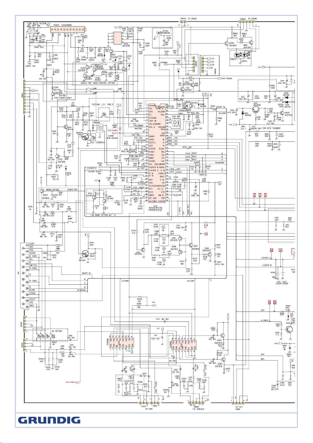
Page 13

PH2LF 16 Phase-2 filter
PH1LF 17 Phase-1 filter
GND3 18 Ground 3 for TV-processor
DECBG 19 Band gap decoupling
AVL 20 Automatic volume levelling
VDIVERB 21 Vertical drive B output
VDIVERA 22 Vertical drive A output
IFIN1 23 IF input 1
IFIN2 24 IF input 2
IREF 25 Reference current input
VSC 26 Vertical sawtooth capacitor
RF AGC 27 Tuner AGC output
SIF 1 28 Audio deemphasize or SIF input
SIF 2 29 Decoupling sound demodulator
GND2 30 Ground 2 for TV processor
SIF AGC 31 Narrow band PLL filter
AV SWITCH 32 Avswitch
H DIR VER 33 Horizontal output
FBT 34 Flyback input/sandcastle output
AMIN 35 AM input
EHT 36 EHT/over voltage protection input
PLL IF 37 IF-PLL loop filter
VIDEO OUT 38 IF video output / selected CVBS output
8V 39 8v
V IN 40 internal CVBS input
GND 41 ground for TV processor
CVBS/Y 42 CVBS/SVHS(Y) input
C IN 43 SVHS (C) input
AUDIO 44 Audio output
INSW2 45 YUV insertion input
S.R 46 R input / V (R-Y) input / PR input
S.G 47 G input / Y input
S.B 48 B input / U (B-Y) input / PB input
BCL 49 Beam current limiter input
BLKI 50 Black current input
RO 51 Red output
GO 52 Green output
BO 53 Blue output
VDDA 54 Analog supply of Closed Caption decoder and digital supply of TV-processor (3.3 V)
VPE 55 Ground
VDDC 56 Digital supply to core (3.3 V)
OSCGND 57 Oscillator ground supply
XTALIN 58 Crystal oscillator input
XTALOUT 59 Crystal oscillator output
RESET 60 Ground
VCC 61 Digital supply to periphery (+3.3 V)
AV/TV 62 AV1 / AV2 mode Output.
SCARTIN/DVD
TRIGGER
63 SCARTINPUT/DVDmode Output.
REMOTE 64 Remote control signal input.
Note
Pin TV SVHS AV1 AV2
62 1 0 0 1
63 1 1 0 0
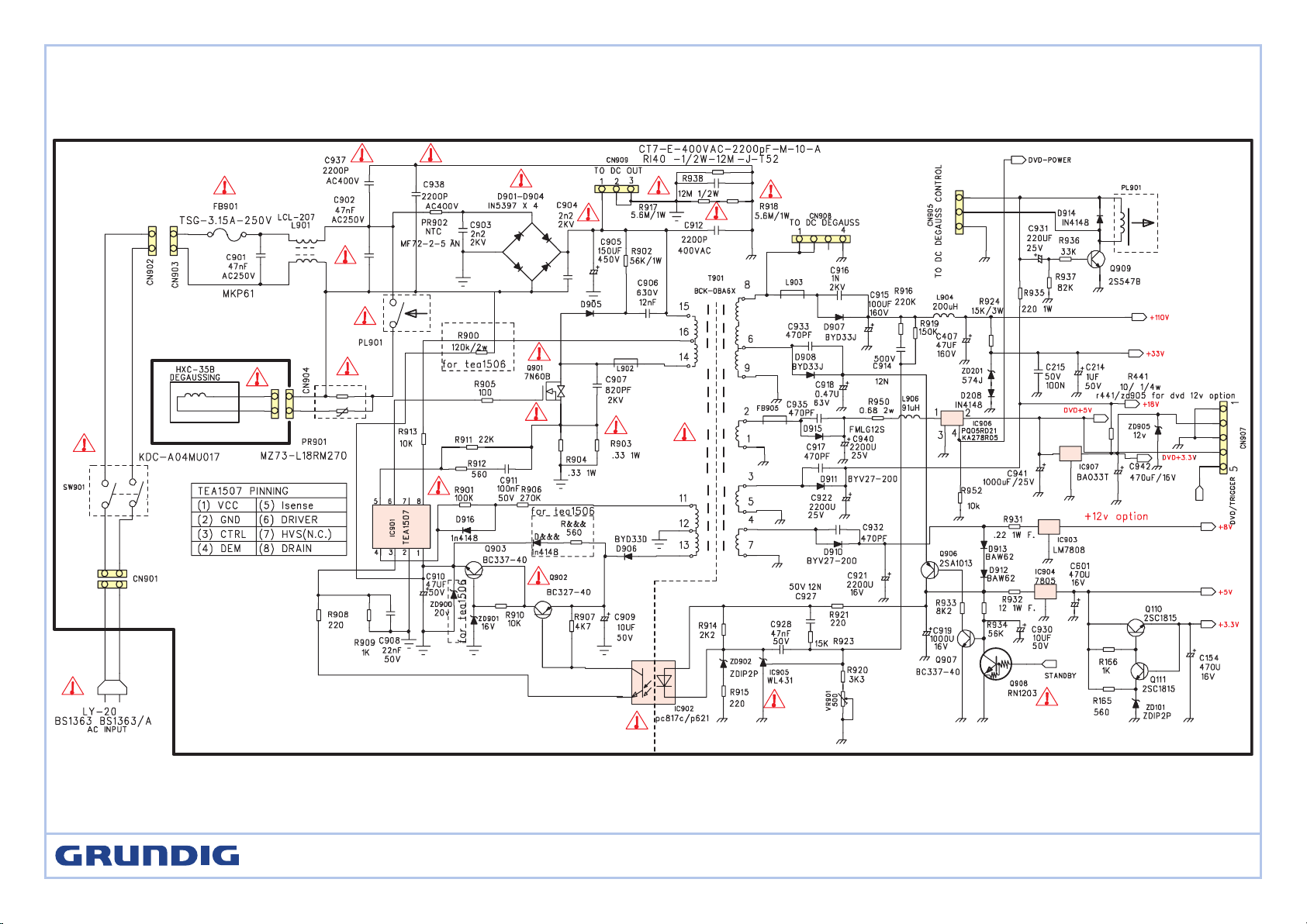
ICs functional description
IC101:TDA9351
SYMBOL PIN DESCRIPTION
STANDBY 1 In STAND BY mode, low level (Power OFF).
For Power ON this pin will be high.
SCL 2 I2C-bus clock line
SDA 3 I2C-bus data line
VT 4 TUNER voltage
SYSTEM 5 TV system control
KEY IN 6 Control keys input
B1AND0(VOL) 7 Sound Volume control PWM output
VOL0 8 Sound mute output
GND 9 Digit ground for µ-controller core and periphery
DVD POWER 10 DVD power control
BAND1 11 STANDBY control
VSSA 12 Analog ground of digital ground of TV-processor
SEC PLL 13 Internally connected
VCC 14 2nd supply voltage TV-processor(+8V)
DECDIG 15 decoupling digital supply of TV-processor
K 15 PFCD 2602 Txt
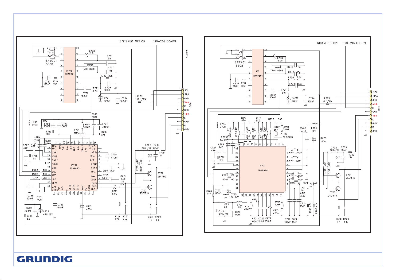
Page 14

TV sound AM -demodulator and audio source switch (TDA9830)
Symbol PIN Function Symbol PIN Function
IFIN
1
sound IF differential input signal EXTIN
9
input signal (from external) to audio switch
n.c.
2
not connected SWITCH
10
switch input select control
C
AGC
3
AGC capacitor
Vp2
11
supply voltage +12 V (alternative)
C
REF
4
REF voltage filtering capacitor MUTE
12
mute control
n.c.
5
not connected
GND
13
ground (0 V)
AMOUT
6
AM demodulator output Vp1
14
supply voltage +5 to +8 V
AMIN
7
input signal (from AM) to audio switch n.c.
15
not connected
AFOUT
8
output signal from audio switch
IFIN
16
sound IF differential input signal
Vertical deflection booster (TDA4863AJ)
Symbol PIN Function Symbol PIN Function
VP1 1 positive supply voltage 1 V-OUT 5
vertical output
VP3 2
flyback generator output INN
6
inverted input of differential input stage
VP2 3
supply voltage 2 for vertical output INP
7
non-inverted input of differential input stage
GND 4
ground or negative supply voltage
Tuner
PIN Function PIN Function
1 AGC 7 +5V
2 vacant 8 vacant
3 Gnd 9 Vt 33V
4 SCL 10 Gnd
5 SDA 11 IF Out
6 +5V
IC102 24C08B/PCF0539
PIN Function
1 GND
2 GND
3 Upper resistance
4 GND
5 SDA data wire
6 SCL clock wire
7 GND
8 +5V Power
K 15 PFCD 2602 Txt
Page 15

V 0 3.8 3.6 3.3 3.5 4.4 5.1 1.8 0 0.18 0.17 0 2.3 8 5 3
PIN 17 18 19 20 21 22 23 24 25 26 27 28 29 30 31 32
V 4 0 4 0.5 0.7 0.8 1.9 1.9 3.9 3.8 1.6 3.2 2.3 0 2.3 0.2
PIN 33 34 35 36 37 38 39 40 41 42 43 44 45 46 47 48
V 0.5 0.3 0 1.7 2.4 3.4 8 3.9 0 3.3 0 3.6 1.4 2.5 2.5 2.5
PIN 49 50 51 52 53 54 55 56 57 58 59 60 61 62 63 64
V 1.9 5.0 2.4 2.4 2.4 3.1 0 3.2 0 1.8 1.7 0 3.2 5.1 3.3 5
TDA4863AJ
PIN 1 2 3 4 5 6 7
13 10.5 13.1 0 0.22 0.2 0.2
TDA9830
PIN 1 2 3 4 5 6 7 8 9 10 11 12 13 14 15 16
1.75 0 2.32 4.37 0 2.2 2.2 2.3 2.2 0 12 3 8 0 1.75
24C08B/PCF0539
PIN 1 2 3 4 5 6 7 8
V 0 0 5.1 0 3.2 0 0 5.1
IC voltages
TDA9351
PIN 1 2 3 4 5 6 7 8 9 10 11 12 13 14 15 16
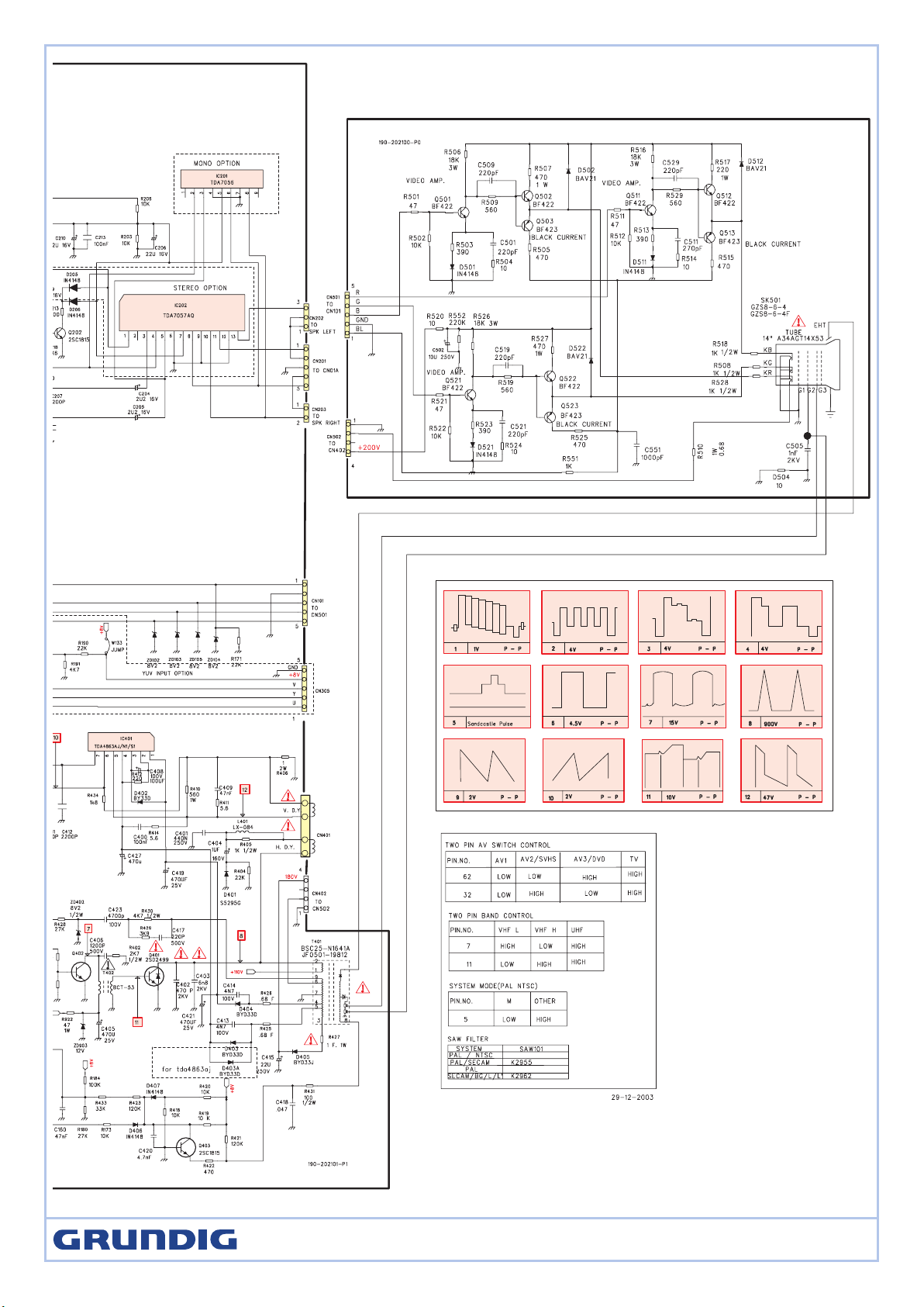
Test point Waveforms
5Vpp
0.9Vpp
1.3Vpp
H
H
1Vpp
V
CRT KB
CRT KGCRT KR
95Vpp
95Vpp
95Vpp
H
H H
TDA9351PIN53
2.5Vpp
2.5Vpp
3.8Vpp
H H
H
TDA9351 PIN52 TDA9351 PIN51
TDA9351 PIN33 TDA9351 PIN34
0.8Vpp
V
TDA9351 PIN21 TDA9351 PIN22 TDA9351 PIN59
1.2Vpp
2.6Vpp
H
H
TDA9351 PIN40
TDA9351 PIN38
K 15 PFCD 2602 Txt
Page 16

DVD Part: Introduction of MTK1389D maintenance
NOTE:
MTK1389D is a type of LSIC for DVD decode .MTK1389D IC consists of RF,SERVO,DSP,DECODE,VIDEO DAC and AUDIO DAC.
1. Under normal power supply conditions, the maintenance plan for MT1389D mono-chip is: first the reset circuit resets the MT1389D, after the crystal
oscillator circuit gave the clock signal to MT1389D, MT1389D will start the initialization check for Flash:E2PROM:SDRAM, after everything is checked
to be normal, it will start initialization check for built-in Audio DAC, servo and motor Driver IC .
2. If the all the a.m. parts are good, then MT1389D will send signal to motor Driver to drive the servo system:pick up then to generate DVD light for col
lection, tracing the main shaft to check if there is any disc, and confirm if it is CD format or DVD format disc. If the disc is in DVD format, the system
will read the data from the disc directly; if it is in CD format built-in servo will drive the CD laser to send out CD light and read the data, the data then
will be amplified through built-in RF amplifier and sent to MT1389D decode part for data processing, released by MPEG and resolved into video data
and audio data, then they will be returned to analog signals through built-in VIDEO DAC:AUDIO DAC.
Decoder section
3. There is power supply, clock and reset, but the system does not work.
- Check if all the address wires required for FLASH are exist, and if they are in normal status, especially check if the A0~A15 of FLASH have normal
signals, if there aren’t, then inspect MT1389D to see if there is faulty soldering. If there are normal signals at A0~A15, check if the address data
signal of MT1389D and SDRAM is normal. If it is normal, then check the signal at A16~A19 of MT1389D; if there are also signals, then check the
video output wires and AV filter circuit; if there is no signal, then check the corresponding pins of MT1389D to see if there is any short circuit, break
or faulty soldering.
4. System in normal operation, but the audio has no sound.
- Because the AUDIO DAC is built in MTK1389D IC.you need to check the lower passing amplifying circuit and the MUTE circuit at the back of the
LPF circuit. Also check if there is any power supply to the LPF circuit.
- Check if the power supply voltage required for playing is at normal level.
Servo Section
5. After the LOGO of the machine shows normally, there is no OSD display. This problem mainly is caused by the abnormality built-in RF and servo,
possible problems may be:
- Built in RF and its surrounding circuits have problems.
- Servo part of MT1389D has problems.
6. OSD display is normal:while there is no action of servo part:feeding motor does not work, main shaft does no turn, possible fault status are:
- The corresponding signals giving by MT1389D to DMSO:FMSO are missing, the reason may be the problem of MT1389D or the communication
between MT1389D and motor Driver IC SA5668.
- Not output from Motor Driver, the reason may be the problem on motor Driver or its corresponding circuit.
7. Servo part in good status, while there is no pick up action:no light, no focus:
- No light, check the power supply:power supply for pick up:, or the light producing driving circuit to see if they are in normal status.
- No focus, check MT1389D to see if there is signal output from FOSO:TRSO. Secondly, check motor driver to see if there is F+:F-:T+:T-signal output.
Thirdly, check the external corresponding circuit of the motor driver to see if there is any problem.
8. All the servo part has action, while it cannot read out the disc
- Check MT1389D if there is RF net picture output, if there isn’t, then it must be the problem of MT1389D and external surrounding circuits, it there is
output, then it might the problem of MT1389D and its surrounding circuits.
- There is RF signal:but not in normal status:then check MT1389D and surrounding circuits.
- Everything is normal, but the disc cannot be read out, check MT1389D and its surrounding circuit
-
K 15 PFCD 2602 Txt
Page 17

Ersatzteilliste
ǵ
Spare Parts List
10 / 2006
POS. NR. ABB. MATERIAL-NR. ANZ. BEZEICHNUNG DESCRIPTION
POS. NO. FIG. PART NUMBER QTY.
GML2300 K 15 PFCD 2602 TXT K 15 PFCD 2602 TXT
0001.000 759551296400 GEH.-VORDERTEIL FRONT CABINET
0002.000 759551297300 RUECKWAND BACK COVER
0003.000 759551296200 KLAPPE DVD FLAP DVD
0007.000 759551297600 LAUTSPRECHER 8 OHM 8 W LOUDSPEAKER 8 OHM 8 W
0015.000 S 759551297400 NETZSCHALTER KDC-A10 POWER SWITCH KDC-A10
0020.000 BR.A36CPAA00X02 PT A36CPAA00X02
0027.000 720117139800 FERNBEDIENUNG HTR-271C REMOTE CONTROL HTR-271C
0030.000 275990218000 LP-BEDIENMODUL CONTROLBOARD
0035.000 275990218200 LP-EMPFANGSMODUL RECEIVER BOARD
0040.000 275990218100 LP-FRONT-AV MODUL FRONT-AV BOARD
0050.000 275990183400 LP-DVD SCART OUTPUT MODUL DVD SCART OUTPUT MODUL
0070.000 S 275990300300 LP-NETZTEILMODUL POWER SUPPLY BOARD
d©
KEIN E-TEIL NO SPARE PART
HINWEIS! NOTE!
IM DEFEKTFALL DER BILDROEHRE IN THE EVENT OF A DEFECTIVE PICTURE
NEHMEN SIE KONTAKT MIT UNSERER TUBE PLEASE CONTACT YOUR SERVICE
HOTLINE AUF
K 15 PFCD 2602 TXT
BESTELL-NR. / ORDER NO.: GML2300
TV
TUN1 759551298300 TUNER TUSVD96HR TUNER TUSVD96HR
T901 S 759551298400 TRAFO BCK-08A6X-1 TRAFO BCK-08A6X-1
T401 S 759551298500 TRAFO JF0501-32806 TRAFO JF0501-32806
T402 S 759551298600 TRAFO BCT-53 TRAFO BCT-53
FB901 S 759550922700 SICHERUNG 3.15AT 250V FUSE 3.15AT 250V
SW01 S 759551297400 NETZSCHALTER KDC-A10 POWER SWITCH KDC-A10
720117233500 BEDIENUNGSANLEITUNG GB, F INSTRUCTION MANUAL GB, F
720130000300 SERVICE DOCUMENT D/GB SERVICE DOCUMENT D/GBP
720108000001 SICHERHEITSMANUAL D/GB/E/F/I SAFETY SERVICE MANUAL D/GB/E/F/I
X = SIEHE GESONDERTE E-LISTE X = SEE SEPARATE PARTS LIST
Es gelten die Vorschriften und Sicherheitshinweise
gemäß dem Service Manual "Sicherheit", Mat.-Nummer 720108000001, sowie zusätzlich die eventuell abweichenden, landesspezifischen Vorschriften!
GRUNDIG Service E - 1
( ! )
The regulations and safety instructions shall be valid
!
as provided by the "Safety" Service Manual, part
number 720108000001, as well as the respective
national deviations.
ÄNDERUNGEN VORBEHALTEN / SUBJECT TO ALTERATION
 Loading...