

Page 1
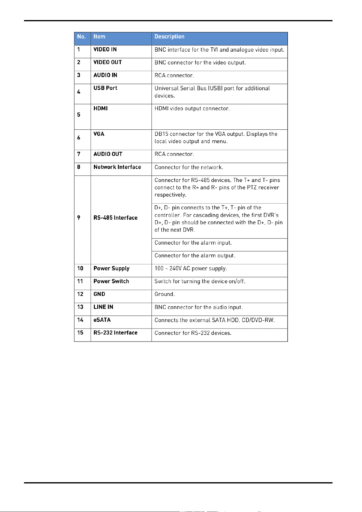
Owner's Manual
HD Video Recorders
GRT-K1104A 4 CH Hybrid HD-TVI / Analog, real time Video Recorder
GRT-K2208A 8 CH Hybrid HD-TVI / Analog, real time Video Recorder
GRY-K4416A 16 CH Tribrid HD-TVI / IP / Analog, real time Video Recorder
GRT-K1104A.173.1.22.10.2015
© ASP AG
Page 2

Page 3

6.2.1. Using the Mouse in Live View ............ 32
Content
1. Introduction ....................................................... 6
1.1. Available Versions ...................................... 7
1.2. Key Features of your NVR .......................... 7
2. Important Safety Instructions ..........................
3. Package Contents ........................................... 10
4. Install
4.1. Connections and Control Keys ................. 11
4.2. HDD Installation ....................................... 13
4.3. Peripheral Connections ........................... 15
5. Getting Started ................................................ 18
5.1. Operation of the NVR ............................... 18
5.1.1. Remote Control ................................. 18
5.1.2. Troubleshooting the Remote
Control ......................................................... 20
n .......................................................11
atio
6.2.2. Quick Setting Toolbar in Live View
Mode ............................................................. 33
6.3. Adjusting the Live View Settings .............. 35
6.4. Digital Spot ............................................... 36
6.5. Manual Video Quality Diagnostics ............ 37
9
7. PTZ Controls .................................................... 38
7.1. Configuring the PTZ Settings ................... 38
7.2. Setting the PTZ Presets, Patrols &
Patterns ........................................................... 38
7.2.1. Customising the Presets ................... 39
7.2.2. Calling the Presets ............................ 39
7.2.3. Customising the Patrols .................... 40
7.2.4. Calling the Patrols ............................. 41
7.2.5. Customising the Patterns .................. 41
7.2.6. Calling the Patterns ........................... 42
5.1.3. USB Mouse Operation ....................... 21
5.1.4. Soft Keyboard .................................... 22
5.2. Menu Overview ......................................... 22
5.3. Starting Up and Shutting Down ............... 22
5.4. Setup Wizard for Basic Configuration ..... 24
5.5. User Login ................................................ 27
5.6. User Logout .............................................. 28
5.7. Menu Operation ........................................ 28
5.8. Adding and Connecting IP Cameras ........ 28
5.8.1. Add Online IP Cameras ..................... 28
6. Live View ......................................................... 31
7.2.7. Customising the Linear Scan Limit ... 42
7.2.8. Calling the Linear Scan ..................... 43
7.2.9. One-touch Park .................................. 43
7.3. PTZ Control Panel .................................... 44
8. Recording Settings .......................................... 45
8.1. Configuring Parameters .......................... 45
8.2. Configuring the Recording Schedule ....... 47
8.3. Configuring the Motion Detection
Recording ........................................................ 50
8.4. Configuring the Alarm Triggered
Recording ........................................................ 51
8.5. Configuring the Manual Recording .......... 53
6.1. Introduction of the Live View .................... 32
6.2. Operations in Live View Mode .................. 32
8.6. Configuring the Holiday Recording .......... 53
Page 4

8.7. Configuring the Redundant Recording .... 54
11.5. Handling an Exceptions Alarm ............. 86
8.8. Configuring the HDD Group for
Recording ........................................................ 56
8.9. Files Protection ........................................ 57
9. Playback .......................................................... 59
9.1. Playing Back Recording Files .................. 59
9.1.1. Playing Back by Channel ................... 59
9.1.2. Playing Back by Time ........................ 61
9.1.3. Playing Back by Event Search ........... 62
9.1.4. Playing Back by Tag .......................... 64
9.1.5. Playing Back by System Logs ........... 66
9.1.6. Playing Back the External File .......... 68
9.2. Auxiliary Functions of Playback ............... 68
9.2.1. Playing Back Frame by Frame .......... 68
9.2.2. Digital Zoom ...................................... 69
9.2.3. Reverse the Playback of
Multi-channel .............................................. 69
10. Backup .......................................................... 70
10.1. Backing up the Recording Files ............. 70
10.1.1. Backing up by Normal
Video Search ................................................ 70
11.6. Setting Alarm Response Actions ......... 86
11.7. Triggering or Clearing an Alarm Output
Manually ........................................................ 89
12. Network Settings ......................................... 90
12.1. Configuring the General Settings ........ 90
12.2. Configuring the Advanced Settings ...... 90
12.2.1. Configuring the PPPoE Settings .... 90
12.2.2. Configuring the Extranet Access ... 90
12.2.3. Configuring DDNS .......................... 91
12.2.4. Configuring the NTP Server ........... 92
12.2.5. Configuring SNMP ......................... 93
12.2.6. Configuring the Remote
Alarm Host ................................................. 93
12.2.7. Configuring Multicast .................... 94
12.2.8. Configuring RTSP ........................... 94
12.2.9. Configuring the Server and
HTTP Ports ................................................. 94
12.2.10. Configuring Email ........................ 95
12.2.11. Configuring NAT ........................... 96
12.3. Checking the Network Traffic .............. 100
10.1.2. Backing up by Event Search ............ 73
10.1.3. Backing up Video Clips .................... 76
10.2. Managing the Backup Devices ............... 77
11. Alarm Settings ............................................. 80
11.1. Setting the Motion Detection Alarm ..... 80
11.2. Setting the Sensor Alarms .................... 82
11.3. Detecting Video Tampering .................. 84
11.4. Detecting a Video Loss Alarm ............... 85
12.4. Configuring the Network Detection ..... 100
12.4.1. Testing the Network Delay and
Packet Loss................................................ 100
12.4.2. Exporting the Network Packet ...... 101
12.4.3. Checking the Network Status ........ 102
12.4.4. Checking the Network Statistics ... 102
13. HDD Management ....................................... 103
13.1. Initialising HDDs ................................... 103
Page 5

13.2. Managing the Network HDD ................. 104
13.3. Managing eSATA HDD
(only for GRY-K4416A) ................................... 105
15.4. Importing/Exporting Configuration
Files ............................................................... 117
15.5. Upgrading the System .......................... 117
13. 4. Managing a HDD Group ........................ 106
13.4.1. Setting up HDD Groups .................. 106
13.4.2. Setting a HDD Property .................. 107
13.5. Configuring the Quota Mode ................. 108
13.6. Checking the HDD Status ...................... 109
13.7. HDD Detection ....................................... 110
13.8. Configuring HDD Error Alarms ............. 111
14. Camera Settings .......................................... 112
14.1. Configuring the OSD Settings ............... 112
14.2. Configuring a Privacy Mask .................. 112
14.3. Configuring Video Parameters ............. 113
15. NVR Management ........................................ 114
15.5.1. Upgrading by a Local Backup
Device ......................................................... 117
15.5.2. Upgrading by FTP .......................... 118
15.6. Restoring the Default Settings ............. 118
16. Other Functions ........................................... 119
16.1. Configuring the RS-232 Serial Port ...... 119
16.2. Configuring the General Settings ........ 119
16.3. Configuring the DST Settings ............... 120
16.4. Configuring More Settings for the Device
Parameters .................................................... 120
16.5. Managing User Accounts...................... 121
16.5.1. Adding a User ................................. 121
16.5.2. Deleting a User .............................. 123
15.1. Viewing the System Information ........... 114
15.2. Searching & Exporting Log Files .......... 114
15.3. Importing/Exporting IP Camera
Information ..................................................... 116
16.5.3. Editing a User ................................. 124
17. Glossary ....................................................... 125
18. Trouble Shooting ......................................... 125
Page 6

1. Introduction
Thank you for purchasing a GRUNDIG video recorder for TVI, CVBS and IP cameras. This manual is for the
recorder models GRT-K1104A, GRT-K2208A and GRY-K4416A.
Before product installation and operation, please become thoroughly familiar with this user manual and other
manuals referenced by this manual.
This user manual, the software and the hardware described here are protected by copyright law. With the
exception of copying for general use within fair use, copying and reprinting the user manual, either partially or in
entirety, or translating it into another language without the consent of ASP AG is strictly prohibited.
This specification may change without prior notice for improvement of product performance.
Product Warranty and Limits of Responsibility:
The manufacturer does not assume any responsibility concerning the sale of this product and does not delegate
any right to any third party to take any responsibility on its behalf. No warranty is offered for any attachments or
parts not supplied by the manufacturer. The product warranty does not cover cases of accidents, negligence,
alteration, misuse or abuse, for example:
- Malfunctions due to negligence by the user
- Deliberate disassembly and replacement by the user
- Connection of a power source other than a properly rated power source
- Malfunctions caused by natural disasters (fire, flood, tidal wave, etc.)
- Replacement of expendable parts (HDD, FAN, etc.)
- Malfunction caused by using an unrecommended HDD
- Malfunction due to HDD failure and not due to a problem in the NVR/DVR
- The warranty period for the Fan is one year after purchase.
This product is not for exclusive use of crime prevention but also for assistance in cases of fire. We take no
responsibility for damage from any incident.
EU Conformity Statement :
This product and - if applicable - the supplied accessories too are marked with "CE" and comply therefore with
the applicable harmonised European standards listed under the Low Voltage Directive 2006/95/EC, the EMC
Directive 2004/108/EC, the RoHS Directive 2011/65/EU.
2012/19/EU (WEEE directive): Products marked with this symbol cannot be disposed of as unsorted municipal
waste in the European Union. For proper recycling, return this product to your local supplier upon the purchase
of equivalent new equipment, or dispose of it at designated collection points.
2006/66/EC (battery directive): This product contains a battery that cannot be disposed of as unsorted municipal
waste in the European Union. See the product documentation for specific battery information. The battery is
marked with a symbol which may include lettering to indicate cadmium (Cd), lead (Pb), or mercury (Hg). For
proper recycling, return the battery to your supplier or to a designated collection point. For more information see:
www.recyclethis.info.
Warning:
1. In case of changing the built-in lithium battery, it should be replaced with the same or a kindred one to prevent
danger of explosion. Since old batteries could be a factor of environment contamination, be cautious how you
treat them.
2. Do not throw the batteries into fire or other heat. Short circuit or disassembly is prohibited.
3. Do not charge the batteries provided with the remote control.
English
Page 7
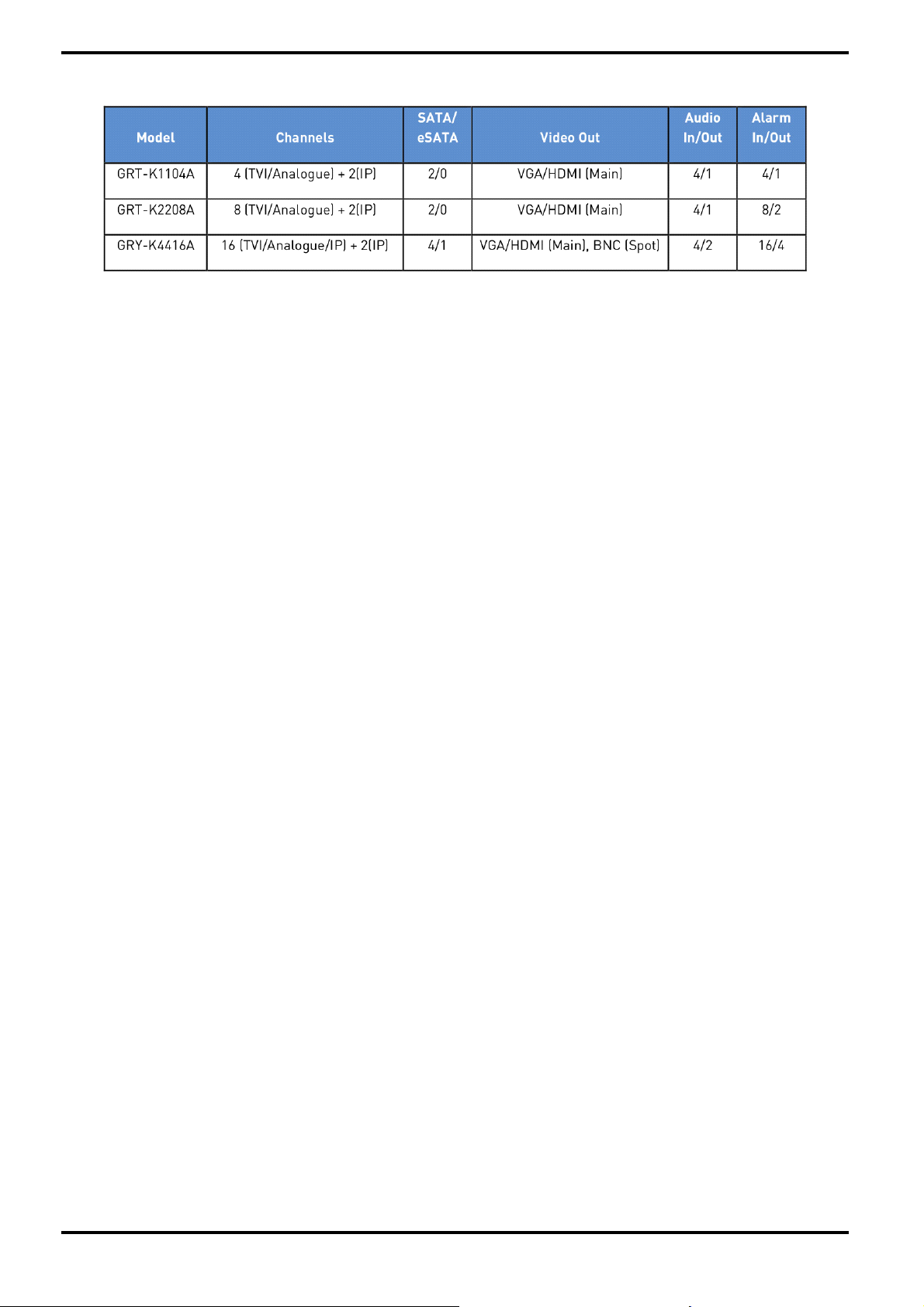
1.1. Available Versions
1.2. Key Features of your DVR
General :
- Connectable to HD-TVI and analogue CVBS cameras.
- Connectable to Grundig & third-party network cameras like ACTI, Arecont, AXIS, Bosch, Brickcom, Canon,
PANASONIC, Pelco, SAMSUNG, SANYO, SONY, Vivotek and ZAVIO, and cameras that adopt ONVIF protocol.
- PAL/NTSC adaptive video inputs.
- Each channel supports dual-stream. Main stream supports up to 1080P resolution and sub-stream supports
up to WD1 resolution.
- Independent configuration for each channel, including resolution, frame rate, bit rate, image quality, etc.
- Encoding for both video stream and video & audio stream, audio and video synchronisation during composite
stream encoding.
- Watermark technology.
Local Monitoring :
- Simultaneous HDMI(Trademark) and VGA outputs with up to 1920×1080 resolution.
- Multiple screen display in live view is supported, and the display sequence of channels is adjustable.
- Live view screen can be switched to group view, manual switch and automatic cycle live view are also provided,
and the interval of automatic cycle can be adjusted.
- Quick setting menu is provided for live view.
- Motion detection, video tampering, video exception alert and video loss alert functions.
- Privacy masking
- Multiple PTZ protocols supported; PTZ preset, patrol and pattern.
- Zooming in by clicking the mouse and PTZ tracing by dragging the mouse.
HDD Management :
- Supports S.M.A.R.T. and bad sector detection
- 8 network disks (NAS /IP SAN disks) can be connected.
- HDD group management.
- Supports HDD standby function.
- HDD property: redundancy, read-only, read/write (R/W).
- HDD quota management; a different capacity can be assigned to different channels.
English
Page 8

Recording and Playback :
- Holiday recording schedule configuration.
- Continuous and event video recording parameters.
- Multiple recording types: manual, continuous, alarm, motion, motion or alarm, motion & alarm
- 8 recording time periods with separated recording types for each day.
- Pre-recording and post-recording for alarm, motion detection for recording, and pre-recording time for
schedule and manual recording.
- Searching recording files by events (alarm input/motion detection).
- Tag adding for recording files, searching and playing back by tags.
- Locking and unlocking recording files.
- Local redundant recording.
- Provides a new playback interface with easy and flexible operation.
- Searching and playing back recording files by camera No., recording type, start time, end time, etc.
- Smart search for the selected area in the video.
- Zooming in during playback.
- Reverse playback of multi-channel views.
- Supports pause, play reverse, speed up, speed down, skip forward, and skip backward during playback, and
locating by dragging the mouse.
- Up to 16-ch synchronous playback in 4CIF real time.
Backup :
- Exports video data to a USB, SATA or eSATA device. (depending on model).
- Exports video clips during playback.
- Management and maintenance of backup devices.
Alarm and Exception :
- Configurable arming time of alarm input/output.
- Alarm for video loss, motion detection, video tampering, HDD full, HDD error, network disconnected, illegal
login, abnormal recording, etc.
- Alarm triggers full screen monitoring, audio alarm, notifying surveillance center, sending email and alarm
output.
- Automatic restoration when system is abnormal.
Other Local Functions :
- Operable by mouse and remote control.
- Three-level user management; admin user is allowed to create many operating accounts and define their
operating permission, which includes the limit to access any channel.
- Operation, alarm, exceptions and log recording and searching.
- Manually triggering and clearing alarms.
- Import and export of device configuration information.
English
Page 9

Network Functions :
- 1 self-adaptive 10M/100M/1000M network interface
- IPv6 is supported.
- TCP/IP protocol, PPPoE, DHCP, DNS, DDNS, NTP, SADP, SMTP, SNMP, NFS, and iSCSI are supported.
- TCP, UDP and RTP for unicast.
- Auto/Manual port mapping by UPnP(Trademark)
- DDNS support with no-ip.org
- Remote reverse playback via RTSP.
- Support access through the platform via ONVIF.
- Remote search, playback, download, locking and unlocking of the recording files, and breakpoint resume is
supported for downloading files.
- Remote parameters setup, remote import/export of device parameters.
- Remote viewing of the device status, system logs and alarm status.
- Remote keyboard operation.
- Remote locking and unlocking of control panel and mouse.
- Remote HDD formatting and program upgrading.
- Remote system restart and shutdown.
- RS-232, RS-485 transparent channel transmission.
- Alarm and exception information can be sent to the remote host
- Remotely starting/stopping the recording.
- Remotely starting/stoping the alarm output.
- Remote PTZ control.
- Remote JPEG capture.
- Two-way audio and voice broadcasting.
- Embedded WEB server.
Development Scalability :
- SDK for Windows and Linux system.
- Source code of application software for demo.
2. Important Safety Instructions
1. Do not place heavy objects on the top of the product.
2. This Product is for indoor use. It is not weatherproof. Please use the product considering its environmental
specifications (Temperature & Humidity). To clean the product, gently wipe the outside with a clean dry cloth.
3. This Product uses AC power of 110V ~ 240V. Be cautious not to cause electric damages to the product.
4. Be careful not to drop the product. Physical shocks may harm the product including the internal HDD. In
addition, be sure the product is secured after installation.
5. This Product is made of metal. Therefore you can hurt human beings if you throw it to them or hit it on them.
When installing the product, be cautious to locate it in safe places where children cannot reach it.
6. If the product does not operate properly, please contact the closest GRUNDIG distributor for after sales
service. Tampering or disassembling the product will cause expiration of the warranty.
7. Security surveillance laws may differ for each country. Therefore, please contact the local region first to avoid
any surveillance law violations.
8. Experience and technical skills are needed for the installation of this product as an improper installation may
cause fire, electric shocks, or defects. Any installation job should be performed by the vendor you purchased this
product from.
The content of this manual can differ according to firmware or software upgrading. The standard and appearance
of the products may be changed for the improvement of quality without prior notice.
English
Page 10
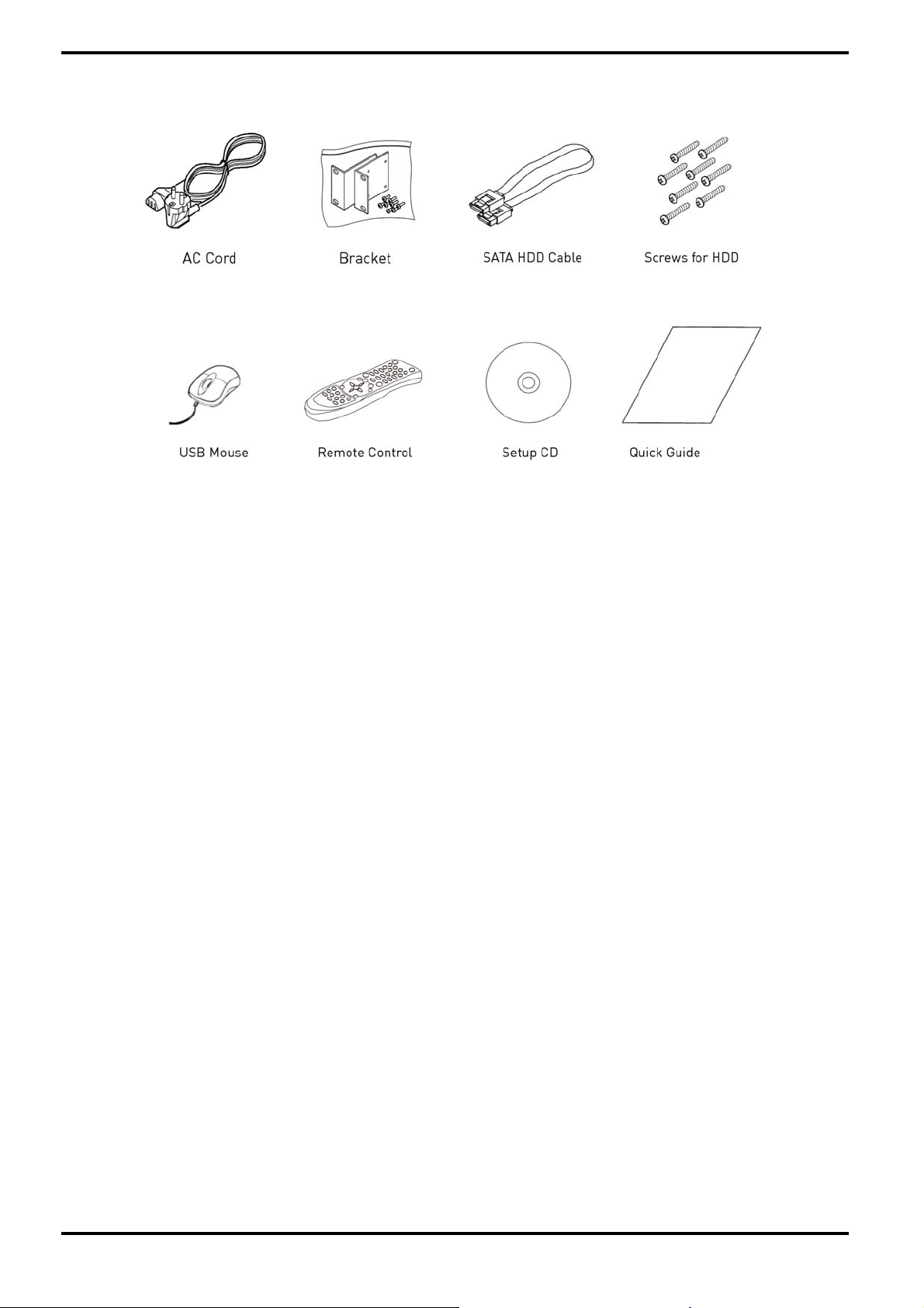
3. Package Contents
These parts are included:
English
Page 11
4. Installation
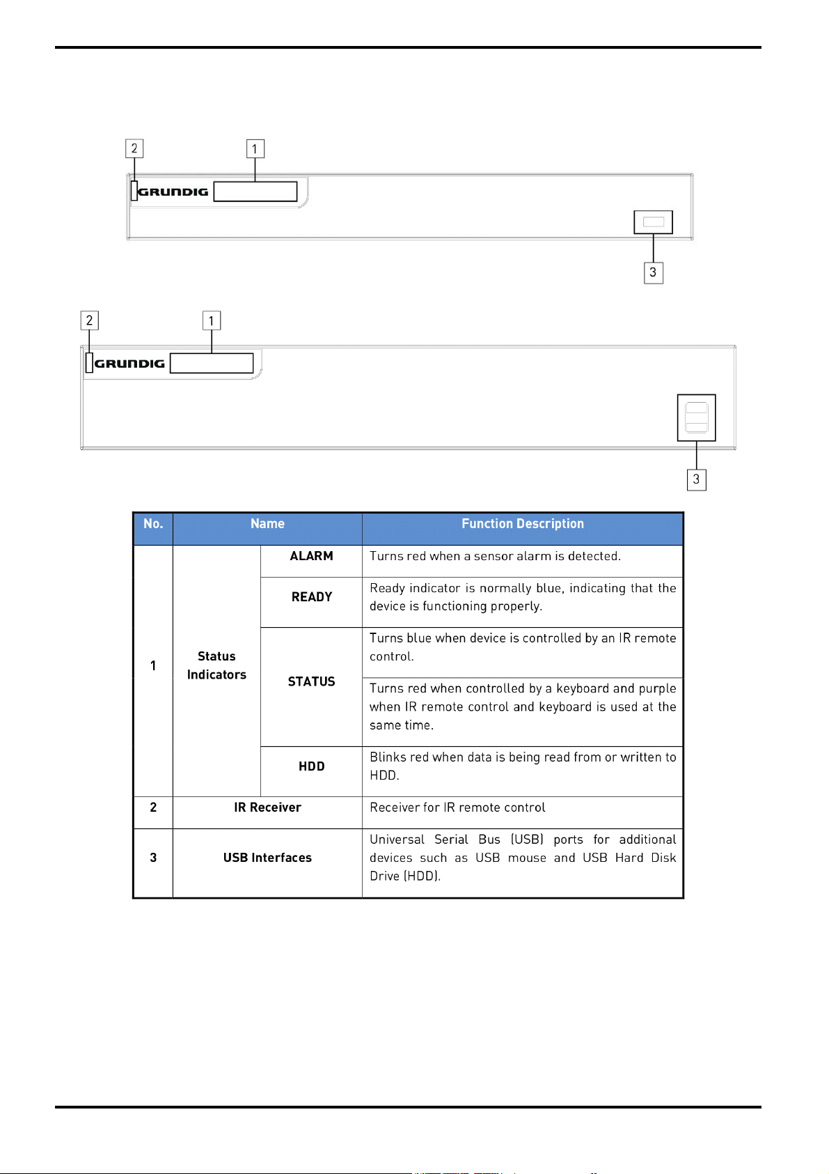
4.1. Connections and Control Keys
Front View:
English
Page 12
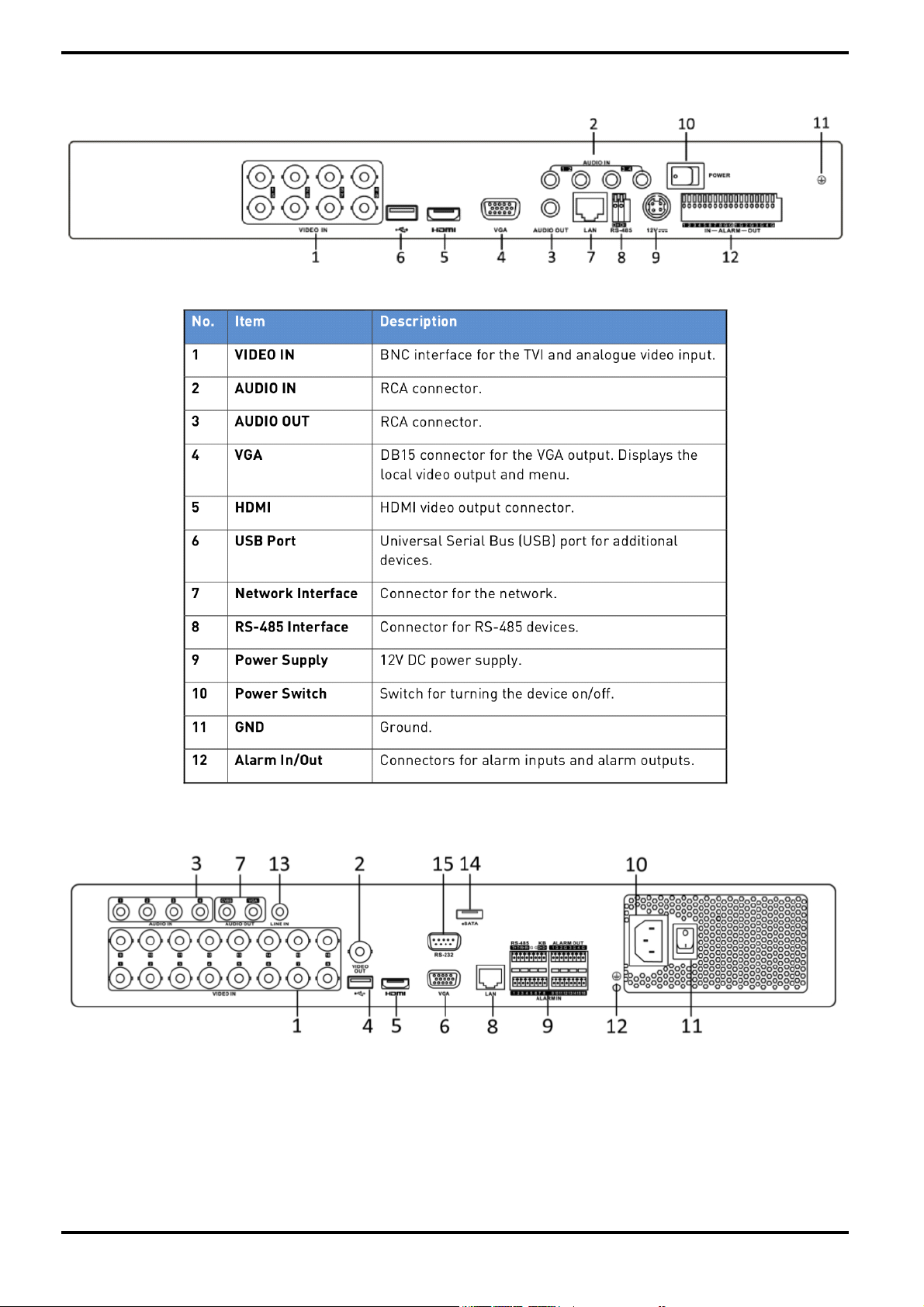
Rear View of the recorder model GRT-K1104A & GRT-K2208A:
Rear View of the recorder model GRY-K4416A:
English
Page 13
4.2. HDD Installation
Check the settings:
Before installation, please read carefully the recommendations below as high internal temperature of the
product can lead to damages and shorten the product’s life cycle.
Recommendations on installing a NVR/DVR in a rack:
Do not seal the inside of the rack where the NVR/DVR is installed. Keep the airflow through the inlet and outlet.
If there is another device installed in the rack, secure the additional space or install an air ventilation. Installation
of an air circulation fan around each inlet and outlet is strongly recommended. (Install the filter for harmful
substances around the inlet or outlet.)
Keep the ambient temperature between 5°C~45°C around the NVR/DVR.
English
Page 14
Warnings if a HDD is installed:
)
Please be extra careful not to damage the HDD as it easily breaks.
During installation, make sure the insulated coat does not come off or is not placed in the wrong place. Do not
lose screws and parts. (If screws and parts are not screwed or assembled correctly, the product may not operate.
Check the HDD compatibility list.
The Partition table must be removed for the HDDs previously used in a PC or other DVR models before
installation.
Before you start:
Disconnect the power from the NVR/DVR before installing a hard disk drive (HDD). A factory recommended HDD
should be used for this installation.
Up to 8 SATA hard disks can be installed on your NVR/DVR.
Tools required:
1 Screwdriver.
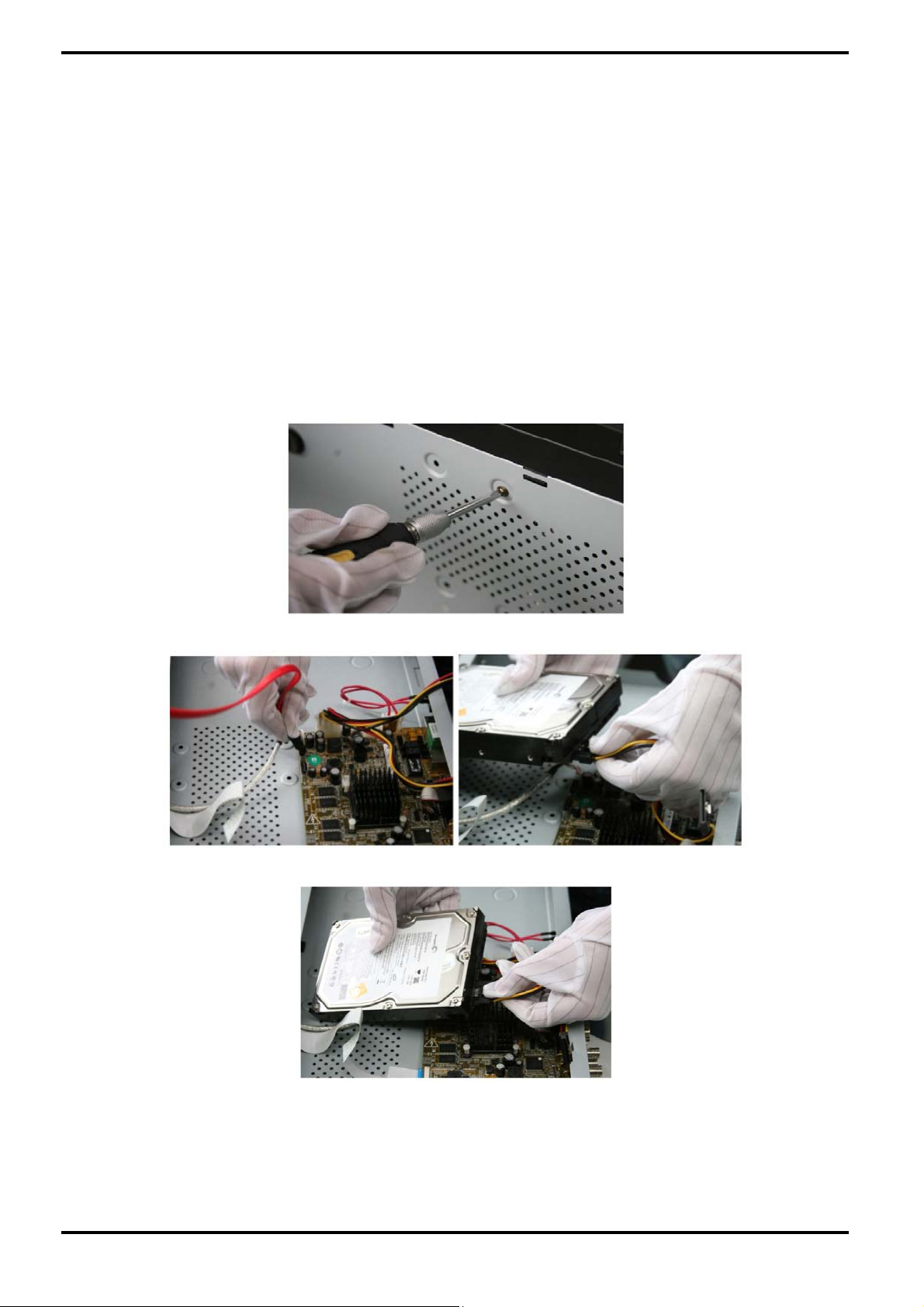
1. Remove the cover from the NVR/DVR by unfastening the screws on the rear and side panel.
2. Connect one end of the data cable to the motherboard of the NVR/DVR and the other end to the HDD.
3. Connect the power cable to the HDD.
English
Page 15
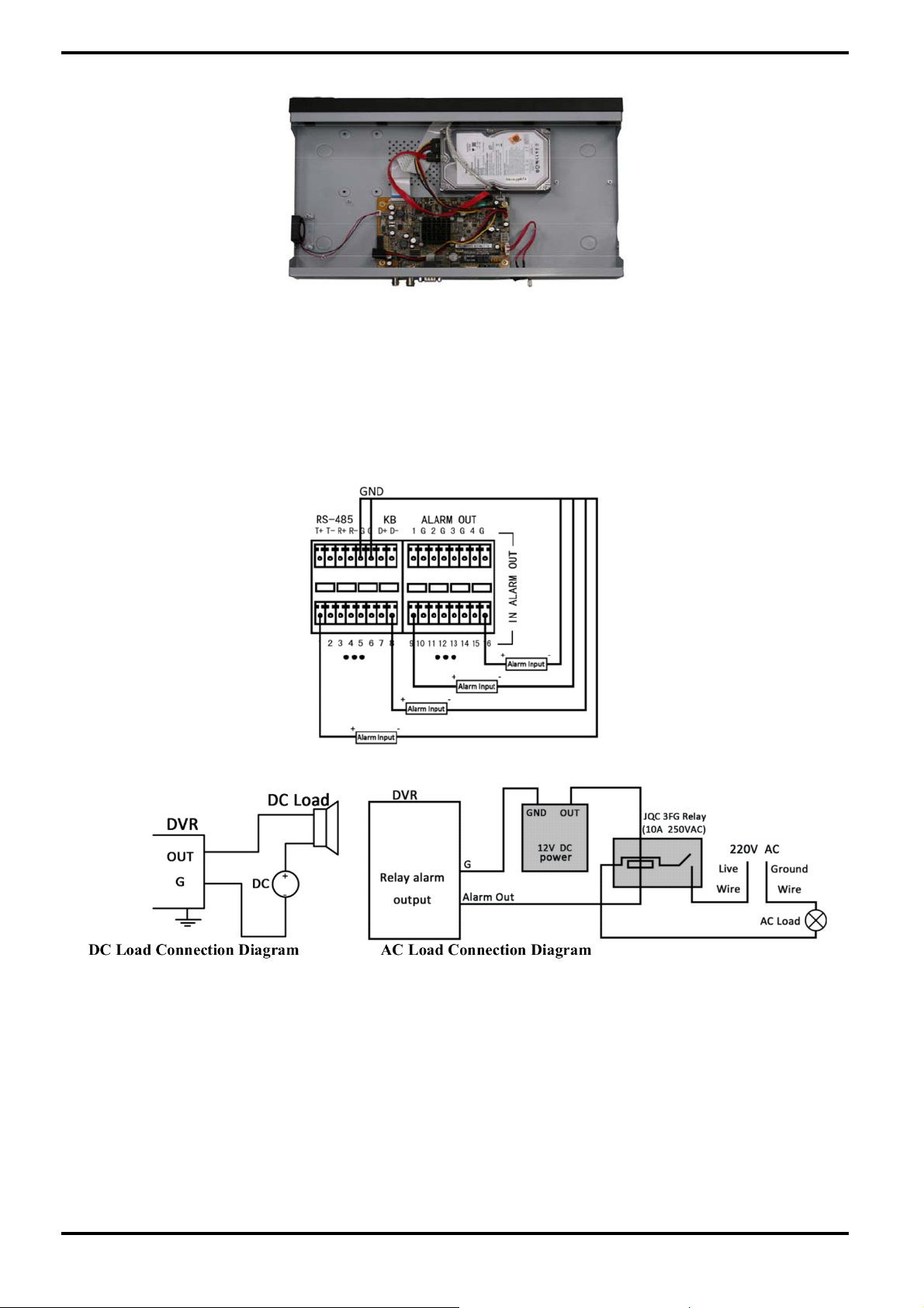
4. Place the HDD on the bottom of the device and then fasten the screws on the bottom to fix the HDD.
5. Re-install the cover of the NVR/DVR and fasten the screws.
4.3. Peripheral Connections
Wiring of the Alarm Input / Output:
The alarm input is an open/closed relay. To connect the alarm input to the device, use the following diagram.
If the alarm input is not an open/close relay, please connect an external relay between the alarm input and the
device.
To connect to an alarm output (AC or DC load), use the following diagram:
For DC load, the jumpers can be used within the limit of 12V/1A safely.
To connect an AC load, jumpers should be left open (you must remove the jumper on the motherboard in the
DVR). Use an external relay for safety (as shown in the figure above).
There are 4 jumpers (JP1, JP2, JP3, and JP4) on the motherboard, each corresponding with one alarm output. By
default, jumpers are connected. To connect an AC load, jumpers should be removed.
Example:
If you connect an AC load to the alarm output 3 of the DVR, then you must remove the JP 3.
English
Page 16

Alarm Connection:
To connect alarm devices to the DVR:
1. Disconnect the pluggable block from the ALARM IN /ALARM OUT terminal block.
2. Press and hold the orange part of the pluggable block; insert signal cables into slots and release the orange
part. Ensure signal cables are in tight.
3. Connect the pluggable block back into the terminal block.
RS-485 and Controller Connection for the models GRT-K1104A/GRT-K2208A:
To connect the PTZ to the models GRT-K1104A/GRT-K2208A:
1. Disconnect the pluggable block from the RS-485 terminal block.
2. Press and hold the orange part of the pluggable block. Insert the signal cables into the slots and release the
orange part. Ensure the signal cables are in tight.
3. Connect R+ on the PTZ to D+ on the terminal block and R- on the controller to D- on the terminal block.
Fasten the stop screws.
4. Connect the pluggable block back into the terminal block.
RS-485 and Controller Connection for the model GRY-K4416A:
English
Page 17
To connect the PTZ to the model GRY-K4416A:
1. Disconnect the pluggable block from the RS-485 terminal block.
2. Press and hold the orange part of the pluggable block. Insert the signal cables into the slots and release the
orange part. Ensure the signal cables are in tight.
3. Connect R+ on the PTZ to T+ on the terminal block and R- on controller to T- on the terminal block. Fasten the
stop screws.
4. Connect the pluggable block back into the terminal block.
To connect a controller to the DVR:
1. Disconnect the pluggable block from the KB terminal block.
2. Press and hold the orange part of the pluggable block. Insert the signal cables into the slots and release the
orange part. Ensure the signal cables are in tight.
3. Connect T+ on the controller to D+ on the terminal block and T- on the controller to D- on the terminal block.
Fasten the stop screws.
4. Connect the pluggable block back into the terminal block.
Make sure both the controller and the DVR are grounded.
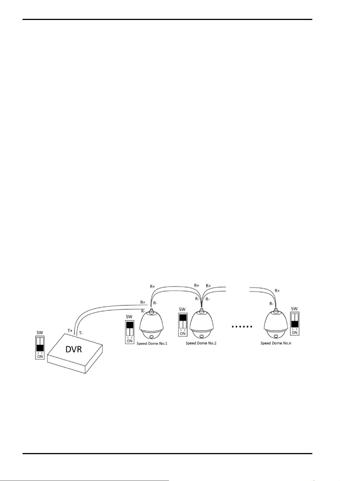
Termination Switch Operation:
The termination switch is placed on the mainboard instead of the rear panel. Open the upper cover and turn
on/off the SW switch if needed.
The termination switch is to connect the DVR with several speed domes, the bus topology can be adopted, which
means the speed domes are connected with each other via the R+ and R- of RS-485 serial interface. But due to
the impedance of 485 wire, the longer the wire is, the greater the impedance gets.
To avoid the signal reduction caused by the great impedance of long distance transmission, please connect two
120Ω resistors in the circuit: one resistor between the DVR and the nearest speed dome, and the other one after
the furthest speed dome.
Steps:
1. Turn on the SW switches on the DVR and the furthest speed dome.
2. Keep the other SW switches off.
The connection diagram and status of each SW switch are shown in the following figure.
English
Page 18
5. Getting Started
5.1. Operation of the DVR
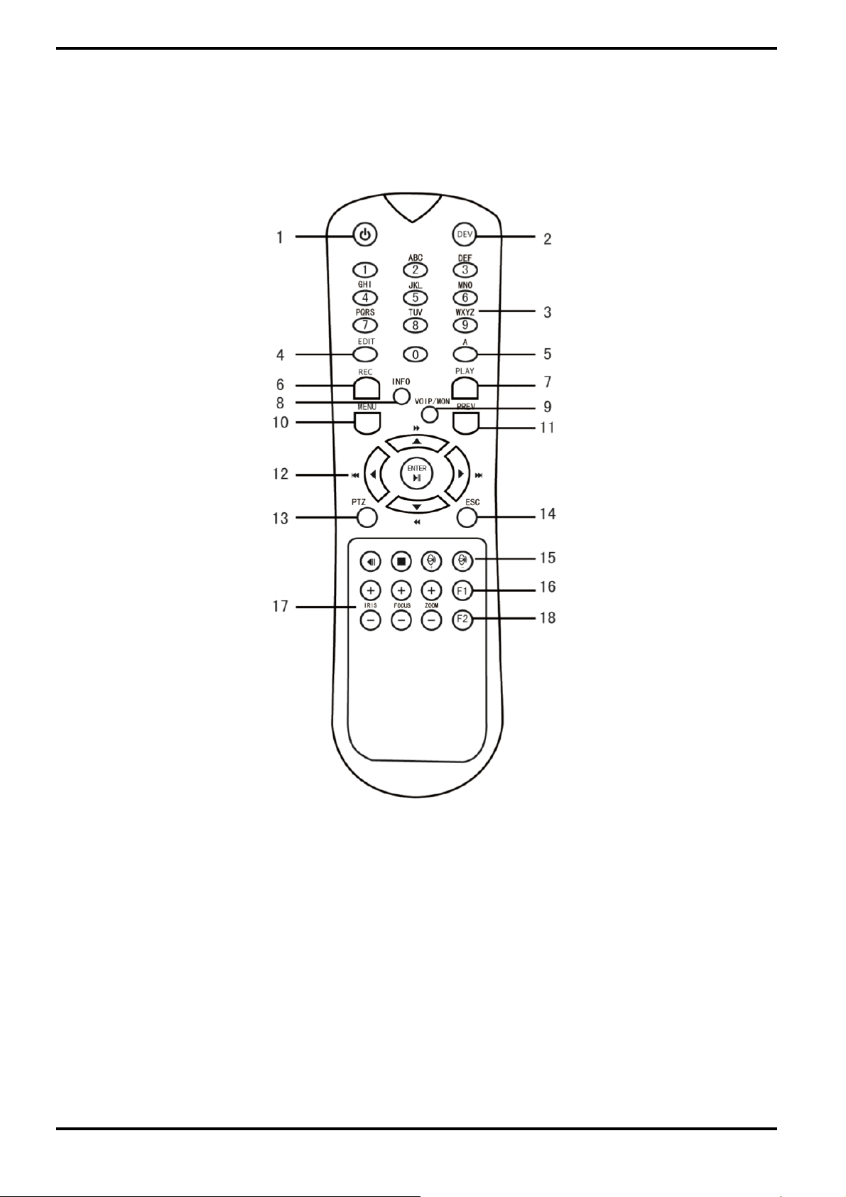
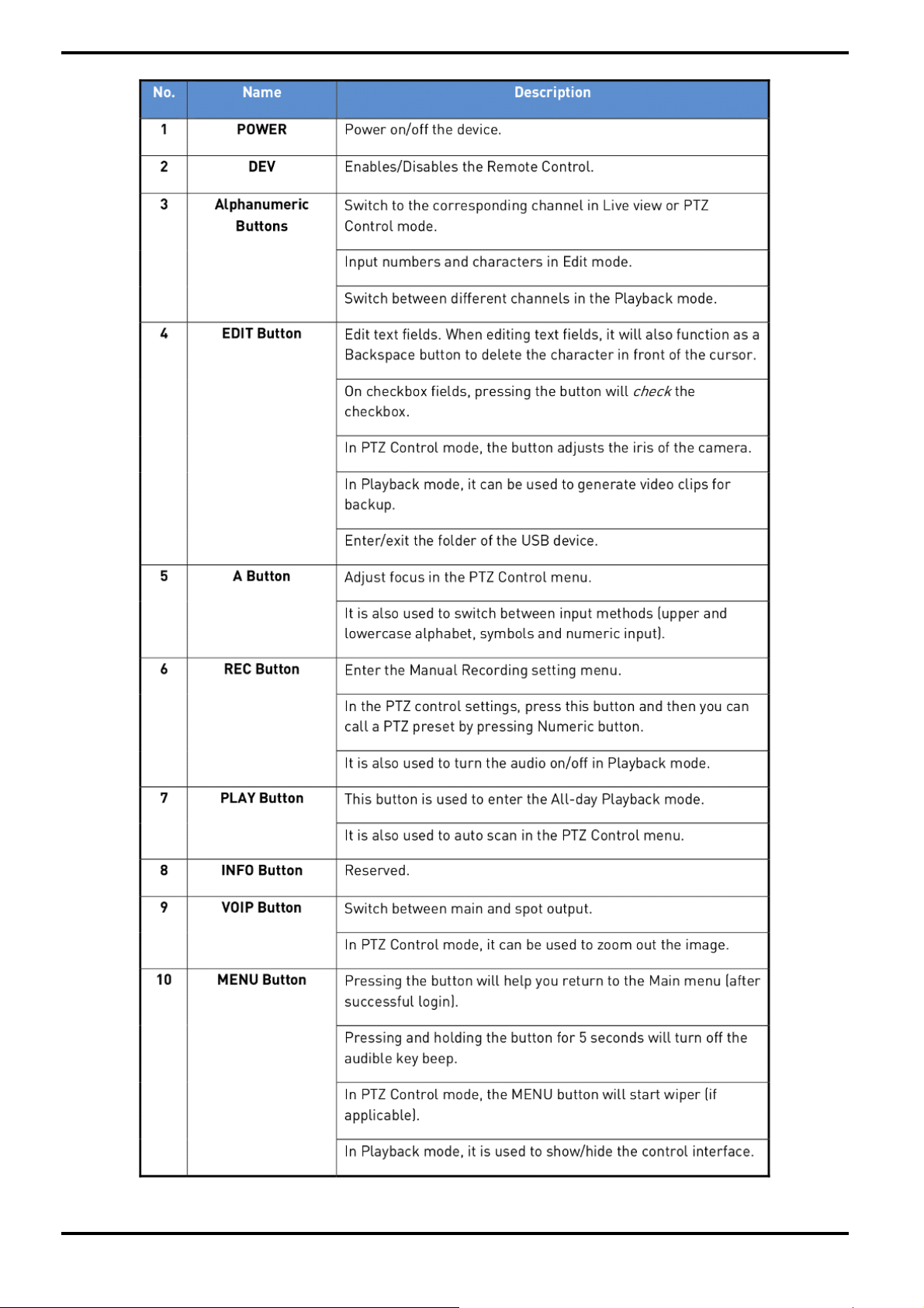
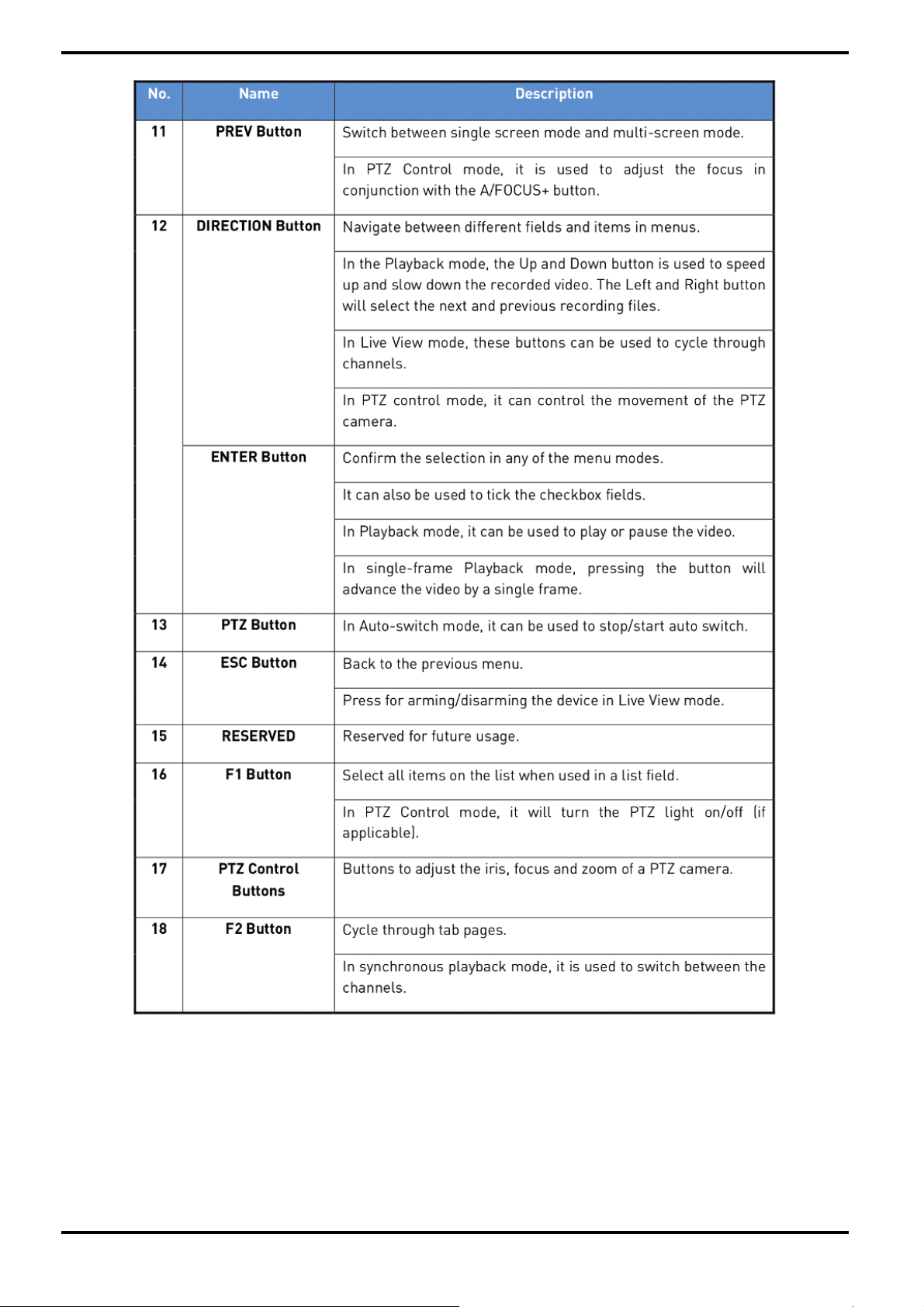
5.1.1. Remote Control
It is possible to use all functions of the NVR/DVR with the remote control. If several NVR/DVRs are set with unique
ID numbers, they can be controlled with one remote control.
English
Page 19
English
Page 20
5.1.2. Troubleshooting the Remote Control
NOTE: Make sure you have installed the batteries properly in the remote control. And you have to aim the remote
control at the IR receiver in the front panel.
If there is no response after you press any button on the remote, follow the procedure below to troubleshoot.
English
Page 21
Setting the ID of the NVR/DVR:
Normally the remote control works out of the box. If the remote control is not working, please set the Remote
Control ID as follows:
Remote Control Setup Steps:
1. Go to Menu > Settings > General > More Settings by operating the front control panel or the mouse.
2. Check and remember the NVR/DVR ID#. The default ID# is 255. This ID# is valid for all the IR remote controls.
3. Press the DEV button on the remote control.
4. Enter the NVR/DVR ID# you set in step 2.
5. Press the ENTER button on the remote.
If the Status indicator on the front panel turns blue, the remote control is operating properly. If the Status
indicator does not turn blue and there is still no response from the remote, please check the following:
1. Batteries are installed correctly and the polarities of the batteries are not reversed.
2. Batteries are fresh and not out of charge.
3. IR receiver is not obstructed.
If the remote still cannot function properly, please change the remote and try again, or contact your dealer.
5.1.3. USB Mouse Operation
A regular 3-button (Left/Right/Scroll-wheel) USB mouse can also be used with this NVR/DVR.
To use an USB mouse:
1. Plug the USB mouse into one of the USB interfaces on the front panel of the NVR/DVR.
2. The mouse should automatically be detected. If in a rare case, the mouse is not detected, the possible reason
may be that the two devices are not compatible, please refer to the recommended device list from your provider.
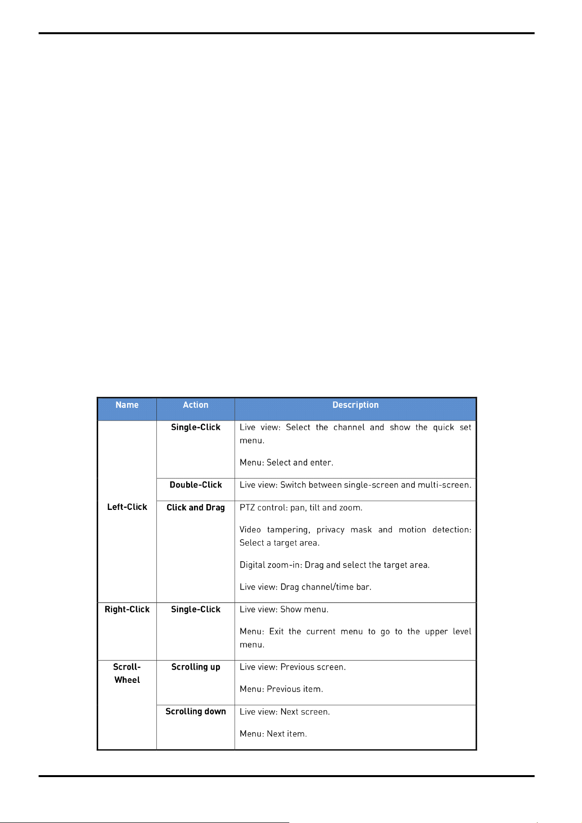
The operation of the mouse:
English
Page 22
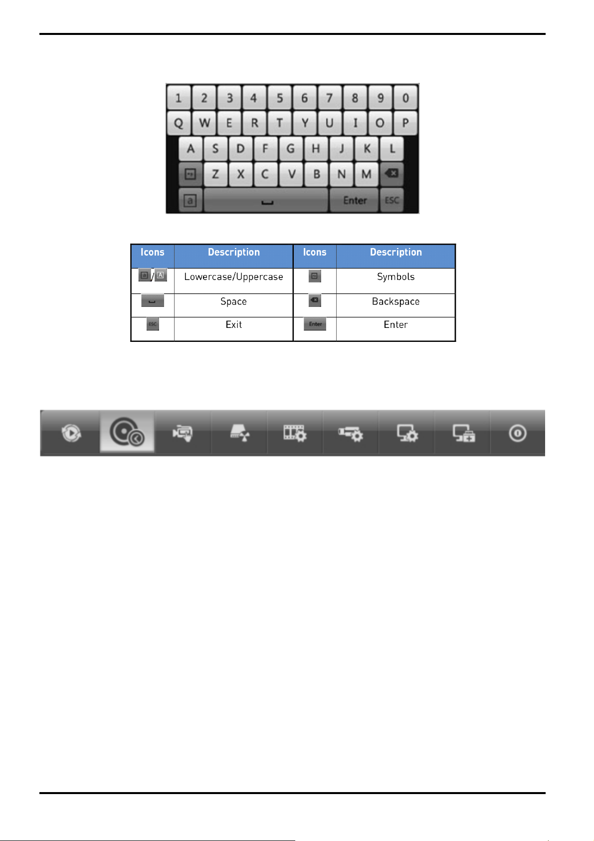
5.1.4. Soft Keyboard
Overview over the Soft Keyboard:
Description of the buttons on the Soft Keyboard:
5.2. Menu Overview
After entering the menu, the menu bar on the top of the screen can be clicked on to set other functions.
From the left to the right, the icon stand for Playback, Export, Manual, HDD, Record, Camera, Configuration,
Maintenance and Shutdown. And the current submenu you are in is marked in light green.
5.3. Starting Up and Shutting Down
Proper startup and shutdown procedures are crucial to expanding the life of the NVR/DVR.
Before you start:
Check that the voltage of the extra power supply is the same as the NVR/DVR’s requirement, and the ground
connection is working properly.
Starting up the NVR/DVR:
Steps:
1. Check whether the power supply is plugged into an electrical outlet. It is HIGHLY recommended that an
Uninterruptible Power Supply (UPS) is used in conjunction with the device. The Power indicator LED on the front
panel should be red, indicating the device gets the power supply.
2. Turn on the power switch on the rear panel if the device starts up for the first time, or press the “Standby”
button on the front panel. The Power indicator LED should turn blue indicating that the unit begins to start up.
3. After startup, the Power indicator LED remains blue. A splash screen with the status of the HDD appears on
the monitor. The row of icons at the bottom of the screen shows the HDD status. ‘X’ means that the HDD is not
installed or cannot be detected.
English
Page 23
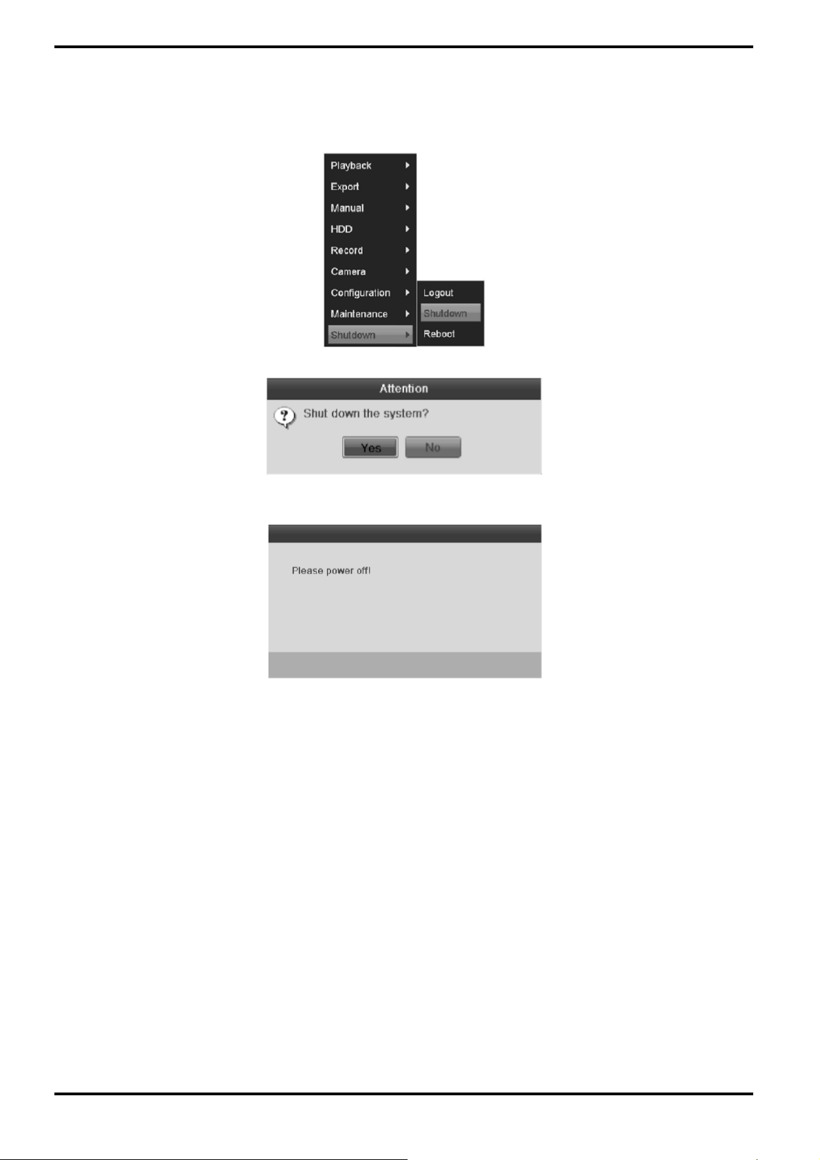
Shutting down the NVR/DVR:
There are two proper ways to shut down the NVR/DVR.
Steps:
1. Enter the Shutdown menu: Menu> Shutdown
2. Click on the "Shutdown" button.
3. Click the “Yes” button.
4. Turn off the power switch on the rear panel when the attention window pops up.
Rebooting the NVR/DVR:
In the Shutdown menu, you can also reboot the NVR/DVR.
Steps:
1. Enter the “Shutdown” menu by clicking Menu> Shutdown.
2. Click on the “Logout” button to lock the NVR/DVR or the “Reboot" button to reboot the NVR/DVR.
English
Page 24
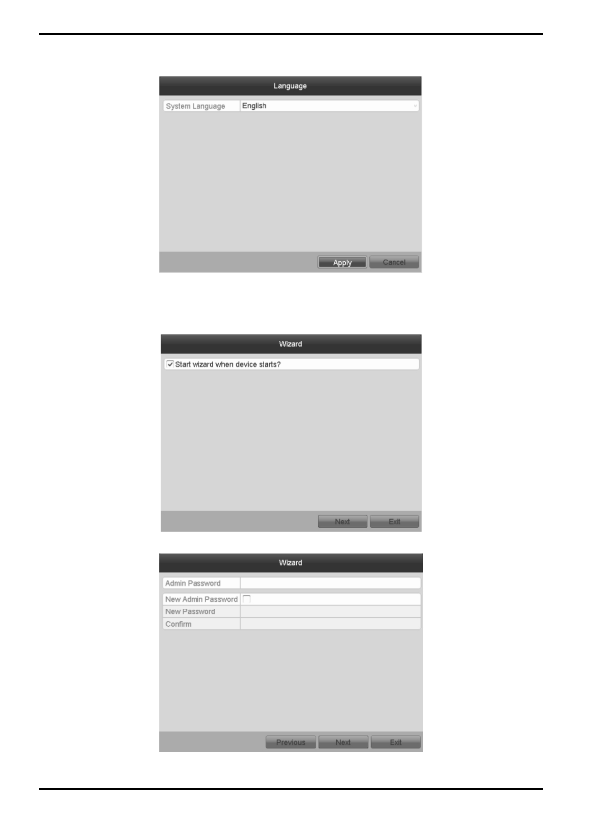
5.4. Setup Wizard for Basic Configuration
By default, the Setup Wizard starts once the NVR/DVR has loaded.
Operating the Setup Wizard:
1. The Setup Wizard can take you through some important settings of the NVR/DVR. If you do not want to use the
Setup Wizard at that moment, click the “Cancel” button. You can also choose to use the Setup Wizard next time by
leaving the “Start wizard when the device starts?” checkbox checked.
2. Click the “Next” button on the Wizard window to enter the Login window.
English
Page 25
3. Enter the admin password. By default, the password is 1234.
4. To change the admin password, check the “New Admin Password” checkbox. Enter the new password and
confirm the password in the given fields.
5. Click the “Next” button to enter the date and time settings window.
6. After the time settings, click the „Next“ button which takes you back to the Network Setup Wizard window, as
shown below.
English
Page 26
7. Click the „Next“ button after you configured the network parameters, which takes you to the HDD
Management window.
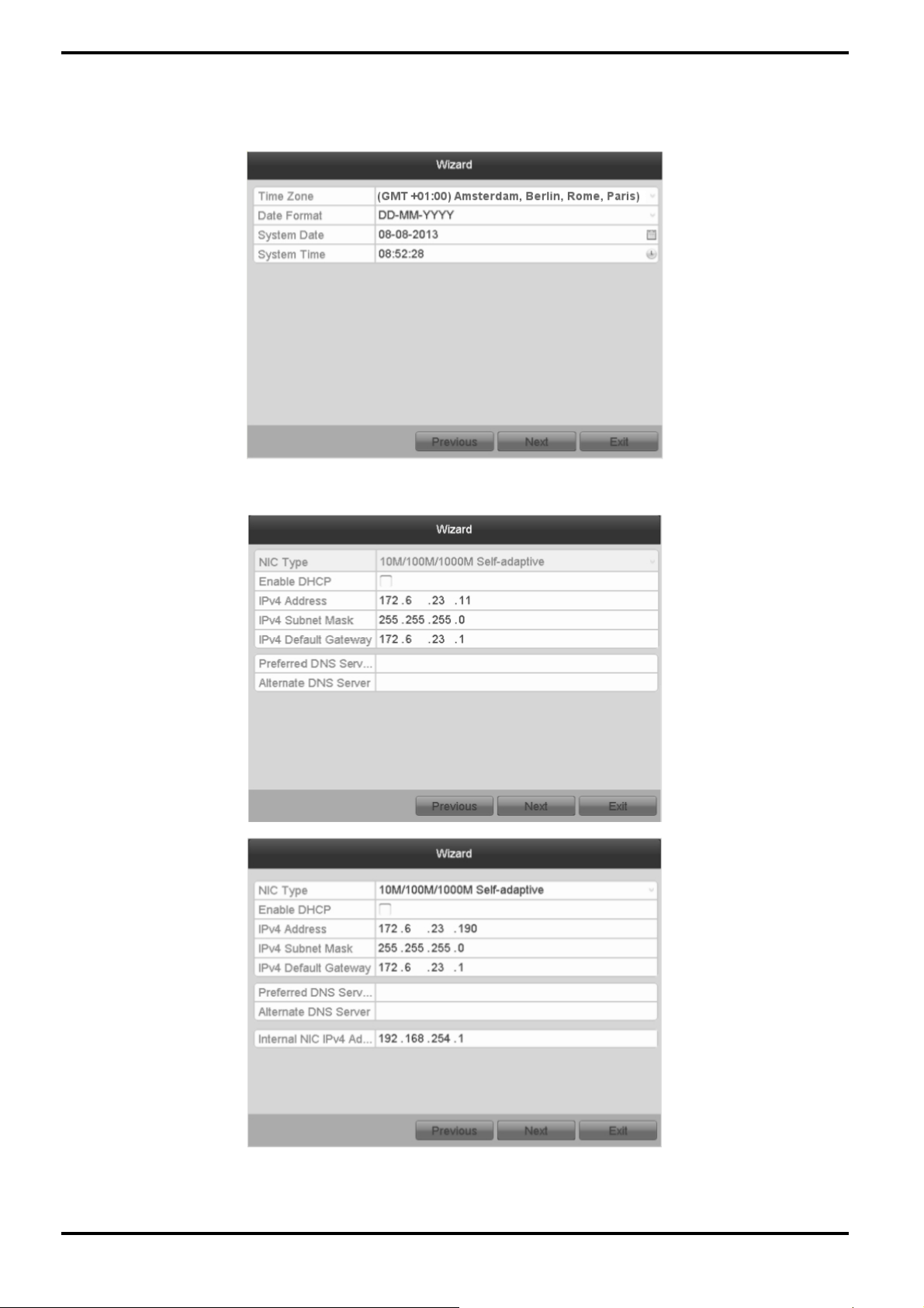
8. To initialise the HDD, click the “Init” button. Initialisation removes all the data saved in the HDD.
9. Click the “Next” button. You enter the Adding IP Camera interface.
10. Click “Search” to find an online IP Camera. Select the IP camera to be added, and click the “Add” button.
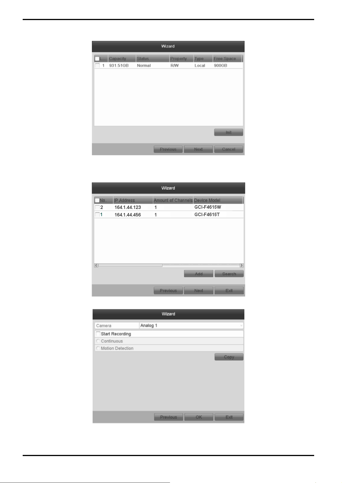
11. Click the “Next” button. Configure the recording for the searched IP Cameras.
English
Page 27
12. Click “Copy” to copy the settings to other channels.
13. Click “OK” to complete the startup Setup Wizard.
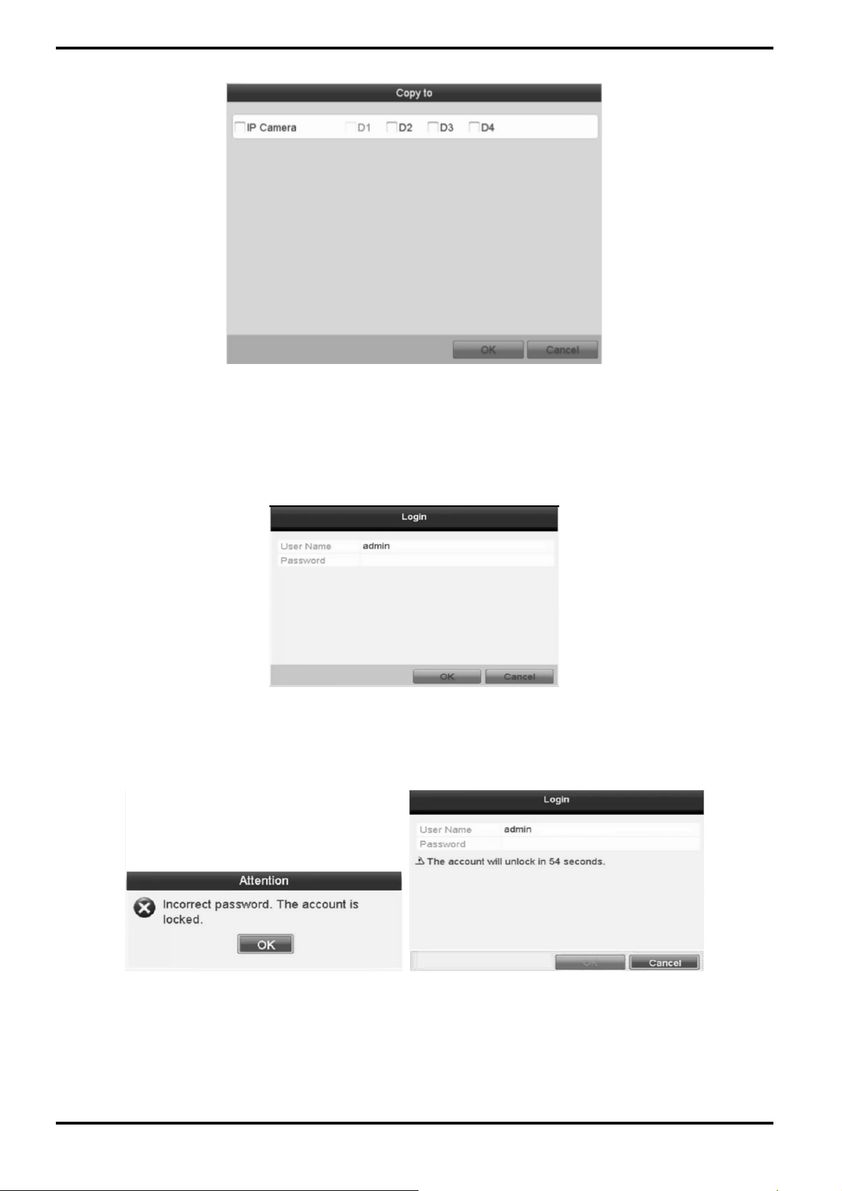
5.5. User Login
To control any function of the NVR/DVR, you must login the device before operating the menu and other functions.
Steps:
1. Select the User Name in the dropdown list.
2. Input the Password.
3. Click OK to log in.
In the Login dialogue box, if you have entered the wrong password for 7 times, the current user account will be
locked for 60 seconds.
English
Page 28

5.6. User Logout
After logging out, the monitor turns to the live view mode and if you want to make a setting or do some other
operation, you need to enter the user name and password again.
Steps:
1. Enter the Shutdown menu: Menu> Shutdown
2. Click “Logout”.
NOTE: After you have logged out of the system, the menu operation on the screen will be invalid. It is required to
input a user name and password to unlock the system.
5.7. Menu Operation
After entering the local operation interface of the device, the main menu bar will be displayed on the top of the
screen. You can click on the icons to enter the corresponding submenus and perform the operations.
The icon of the current submenu is marked in light green.
To exit from the main menu bar, right-click on the screen and you will go back to the live view interface.
5.8. Adding and Connecting IP Cameras
5.8.1. Add Online IP Cameras
The main function of the NVR/DVR is to connect the network cameras and recording the video received from
them. So before you can get a live view or recording of the video, you should add the network cameras to the
connection list of the device.
English
Page 29
Before you start:
Ensure the network connection is valid and correct. For detailed checking and configuring of the network, please
see Chapter 9.3 "Checking Network Traffic" and the Chapter "Configuring Network Detection".
Steps:
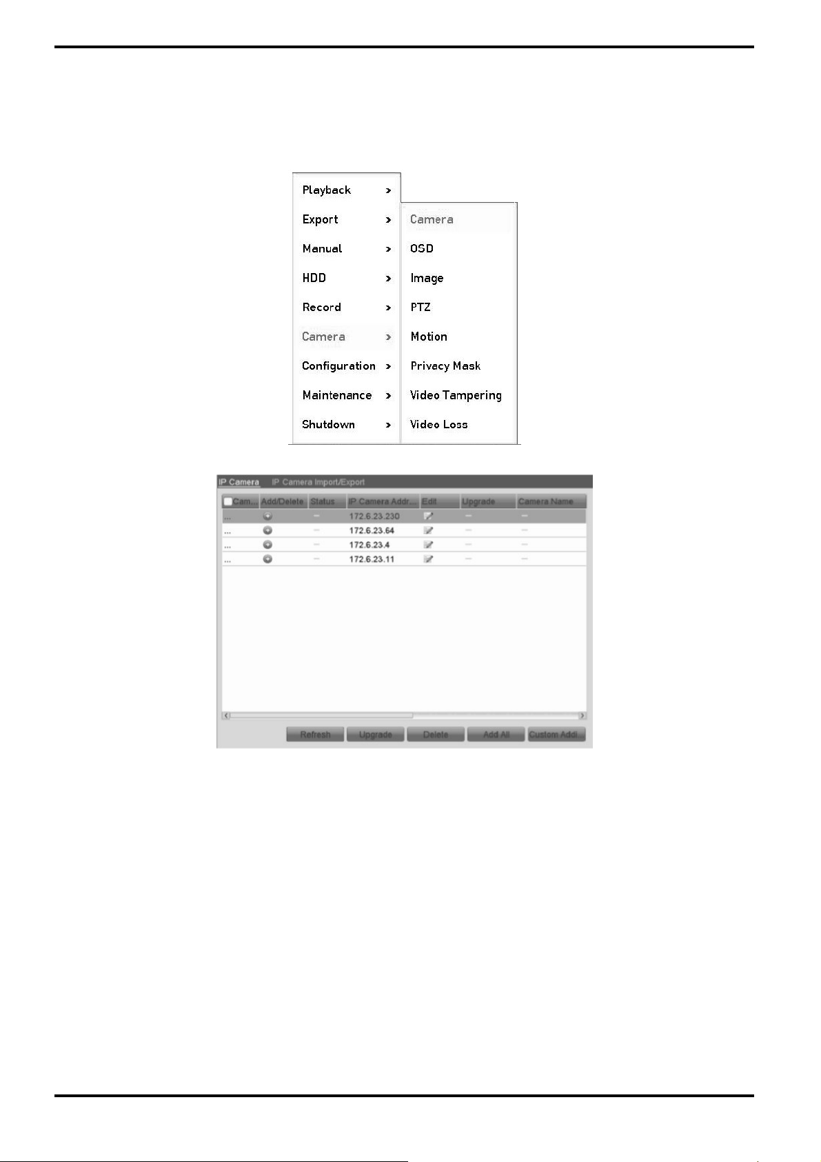
1. Enter the Camera Management interface: Menu> Camera> Camera
2. Select “Add IP Camera” in the pop-up menu to enter the IP Camera Management interface.
English
Page 30
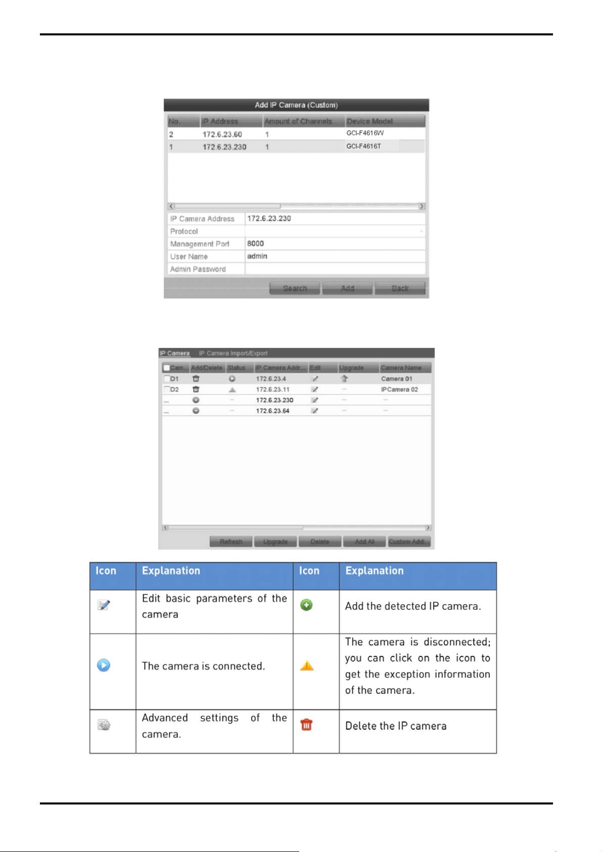
3. The online cameras with the same network segment will be displayed in the camera list. Click the “+” button
to add the camera.
4. To add other IP cameras:
1) Click the “Custom Adding” button to pop up the “Add IP Camera (Custom)” interface.
2) You can edit the IP address, protocol, management port, and other information of the IP camera to be added.
3) Click “Add” to add the camera.
4) The successfully added IP cameras are listed in the interface:
English
Page 31

5. Import/Export the configuration file of the IP cameras.
Import the configuration file of the IP cameras to the device:
Connect the backup device on which the configuration file is stored.
1) Click on the “IP Camera Import/Export” tab.
2) Select the backup device from the drop-down list and click the “Refresh” button to get the latest information
of the backup device.
3) Select the configuration file of the IP camera from the list.
4) Click the “Import” button to import the IP cameras to the device.
5) Click “OK” on the pop-up message box after the importing process is complete. The imported IP cameras will
be displayed on the IP Camera Management interface.
Export the configuration file of the IP cameras to the backup device:
Connect the backup device on which the configuration file is stored to the device.
1) Click on the “IP Camera Import/Export” tab.
2) Select the backup device from the drop-down list. You can click the “Refresh” button to get the latest
information of the backup device.
3) Click the “Export” button to export the configuration file of the IP cameras to the backup device.
4) Click “OK” on the pop-up message box after the exporting process is complete. The configuration file of the IP
cameras will be displayed in a list.
English
Page 32

6. Live View
6.1. Introduction of the Live View
The Live View shows you the video image received from each camera in real time. The NVR/DVR automatically
enters Live View mode when powered on. It is also at the very top of the menu hierarchy, thus pressing the ESC
many times (depending in which menu you are in) takes you to Live View mode.
Live View Icons:
In the live view mode, there are icons at the upper-right of the screen for each channel, showing the status of the
recording and alarm in the channel, so that you can know whether the channel is recorded, or whether there are
any alarms occurring as soon as possible.
6.2. Operations in Live View Mode
In Live View mode, there are many functions provided. The functions are listed below.
- Single Screen: showing only one screen on the monitor.
- Multi-screen: showing multiple screens on the monitor simultaneously.
- Auto-switch: the screen is auto-switched to the next one. And you must set the dwell time for each screen in the
configuration menu before enabling the auto-switch:
Menu> Configuration> Live View> Dwell Time.
- Start Recording: Continuous recording and motion detection recording are supported.
- Output Mode: Select the output mode from Standard, Bright, Gentle or Vivid.
- Add IP Camera: The shortcut to the IP camera management interface.
- Playback: Playback the recorded videos for the current day.
6.2.1. Using the Mouse in Live View
In Live View mode, when you right-click on the screen or move the mouse to the bottom of the screen, the main
menu button and the live view toolbar will appear:
English
Page 33

6.2.2. Quick Setting Toolbar in Live View Mode
On the screen of each channel, there is a quick setting toolbar which shows when you single click the mouse in
the corresponding screen.
English
Page 34

For details about the different buttons from the table, please refer to the explanations below:
Instant Playback :
Instant Playback only shows the recording from the last five minutes. If no recording is found, it means there was
no recording during the last five minutes.
Digital Zoom :
Digital Zoom can zoom in the selected area to the full screen. You can left-click and draw to select the area for
zooming in.
Image Settings :
The Image Settings icon can be selected to enter the Image Settings menu.
English
Page 35

You can set here the image parameters like brightness, contrast, saturation and hue.
Live View Strategy :
Live View Strategy can be selected to set strategy, including Real-time, Balanced, Fluency.
6.3. Adjusting the Live View Settings
The Live View settings can be customised according to different needs. You can configure the output interface,
dwell time for the screen to be shown, mute or turning on the audio, the screen number for each channel, etc.
Steps:
1. Enter the Live View Settings interface: Menu> Configuration> Live View
English
Page 36
The settings available in this menu include:
- Video Output Interface: Designates the output to configure the settings for.
- Live View Mode: Designates the display mode to be used as default in this Video Output Interface.
- Dwell Time: The time in seconds to dwell between the switching of channels when “Auto-switch” in Live View is
enabled.
- Enable Audio Output: Enables/disables audio output for the selected video output.
- Event Output: Designates the output to show the event video.
- Full Screen Monitoring Dwell Time: The time in seconds to show the alarm event screen.
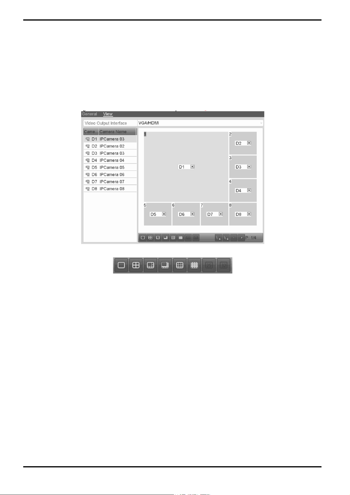
2. View Tab:
Arrange the camera order for each Video Output Interface.
1) Select a View mode by pushing one of the View Buttons shown below:
2) Select a small window, and double-click on the channel number to display the channel in the window.
If you do not want the camera to be displayed in the live view interface, click the corresponding “X” button to stop
it.
You can also click on the “(Forward image)” button to start the live view for all the channels and click the “(Delete
Image)” button to stop all the live views.
3) Click the “Apply” button to save the setting.
6.4. Digital Spot
This chapter is only applicable to GRY-K4416A.
Sometimes you need to get a remote view of many channels in real time from the web browser or CMS (Client
Management System) software. In order to decrease the bandwidth requirements without affecting the image
quality, the Digital Spot is supported as an option for you.
Steps:
1. Enter the Live View Settings interface: Menu> Configuration> Live View
2. Select the Digital Spot tab.
3. Check the checkbox after "Enable Digital Spot".
4. Configure the Frame Rate, Max. Bitrate Mode and Max. Bitrate.
5. Click the "Apply" button to activate the settings.
After you set the Digital Spot, you can get a view in the remote client or web browser of 16 channels in one screen.
English
Page 37

6.5. Manual Video Quality Diagnostics
The video quality of the analogue channels can be diagnosed manually and you can view the diagnostic results in
a list.
Steps:
1. Enter the "Manual Video Quality Diagnostics" interface: Menu> Manual> Manual Video Quality Diagnostics.
2. Check the checkboxes to select the channels for diagnostics.
3. If you click the button "Diagnose", the results will be displayed in a list. You can view there the video status
and diagnostics time of the selected channels.
NOTE:
- Connect the camera to the device for the video quality diagnostics.
- Three exception types can be diagnosed: Blurred Image, Abnormal Brightness and Color Cast.
English
Page 38

7. PTZ Controls
7.1. Configuring the PTZ Settings
The purpose of this function is to follow the procedure to set the parameters for PTZ. The configuring of the PTZ
parameters should be done before you control the PTZ camera.
Please note: Only cameras using Grundig-1 protocol make use of all the PTZ functions. Cameras using Grundig2, ONVIF or any other protocol might need to be configured directly in the camera OSD.
Steps:
1. Enter the PTZ Settings interface: Menu >Camera> PTZ
2. Click the RS-485 Settings button to set the RS-485 parameters.
3. Choose the camera for PTZ setting in the “Camera” dropdown list.
4. Enter the parameters of the PTZ camera.
NOTE: All the parameters should be exactly the same as the PTZ camera parameters.
5. Click the “Apply” button to save the settings.
7.2. Setting the PTZ Presets, Patrols & Patterns
Before you start:
Please make sure that the presets, patrols and patterns should be supported by PTZ protocols.
English
Page 39

7.2.1. Customising the Presets
Follow the steps to set the Preset location which you want the PTZ camera to point to when an event takes place.
Steps:
1. Enter the PTZ Control interface: Menu> Camera> PTZ
2. Use the directional button to wheel the camera to the location where you want to set the limit, and click the
“Left Limit” or “Right Limit” button to link the location to the corresponding limit.
NOTE: A speed dome starts a linear scan from the left limit to the right limit, and you must set the left limit on the
left side of the right limit, as well the angle from the left limit to the right limit should be no more than 180º.
7.2.2. Calling the Presets
This feature enables the camera to point to a specified position such as a window when an event takes place.
Steps:
1. Click the button “PTZ” in the lower-right corner of the PTZ setting interface;
Or press the “PTZ” button on the front panel or click the “(PTZ Control)” icon in the quick setting bar, or select
the “PTZ” option in the right-click menu to show the PTZ control panel.
2. Choose a Camera in the dropdown list.
3. Click the “>” button to show the general settings of the PTZ control.
English
Page 40

4. Click to enter the preset No. in the corresponding text field.
5. Click the “Call Preset” button to call it.
7.2.3. Customising the Patrols
Patrols can be set to move the PTZ to different key points and have it stay there for a set duration before moving
on to the next key point. The key points are corresponding to the presets. The presets can be set following the
steps above in the chapter “Customising the Presets”.
Steps:
1.Enter the PTZ Control interface: Menu> Camera> PTZ
2. Select the Patrol No. in the drop-down list of ”Patrol”.
3. Click the “Set” button to add key points for the patrol.
4. Configure the key point parameters, such as the Key Point No., duration of staying for one key point and speed
of patrol. The key point is corresponding to the preset. The “Key Point” No. Determines the order which the PTZ
will follow while cycling through the patrol. The “Duration” refers to the time span for staying at the
corresponding key point. “Speed” defines the speed at which the PTZ will move from one key point to the next.
5. Click the “Add” button to add the next key point to the patrol, and you can click the “OK” button to save the key
point to the patrol.
You can delete all the key points by clicking the “Clear” button for the selected patrol, or click the “Clear All”
button to delete all the key points for all patrols.
English
Page 41

7.2.4. Calling the Patrols
Calling a patrol makes the PTZ move according the predefined patrol path.
Steps:
1. Click the button “PTZ” in the lower-right corner of the PTZ setting interface;
Or press the PTZ button on the front panel or click the “PTZ Control” icon in the quick setting bar, or select the
PTZ option in the right-click menu to show the PTZ control panel.
2. Click the “>” button to show the general settings of the PTZ control.
3. Select a patrol in the dropdown list and click the “Call Patrol” button to call it.
4. You can click the “Stop Patrol” button to stop calling it.
7.2.5. Customising the Patterns
Patterns can be set by recording the movement of the PTZ. You can call the pattern to make the PTZ movement
according to the predefined path.
Steps:
1. Enter the PTZ Control interface: Menu> Camera> PTZ
2. Choose the pattern number in the dropdown list.
3. Click the “Start” button and click the corresponding buttons in the control panel to move the PTZ camera, and
click the “Stop” button to stop it.
The movement of the PTZ is recorded as the pattern.
English
Page 42

7.2.6. Calling the Patterns
Follow the procedure to move the PTZ camera according to the predefined patterns.
Steps:
1. Click the button “PTZ” in the lower-right corner of the PTZ setting interface;
Or press the PTZ button on the front panel or click the “PTZ Control” icon in the quick setting bar, or select the
PTZ option in the right-click menu to show the PTZ control panel.
2. Click the ”>” button to show the general settings of the PTZ control.
3. Click the “Call Pattern” button to call it.
4. Click the “Stop Pattern” button to stop calling it.
7.2.7. Customising the Linear Scan Limit
The Linear Scan can be enabled to trigger the scan in the horizontal direction in the predefined range.
NOTE: This function is supported by some models.
Steps:
1. Enter the PTZ Control interface: Menu> Camera> PTZ
English
Page 43

2. Use the directional button to wheel the camera to the location where you want to set the limit, and click the
“Left Limit” or “Right Limit” button to link the location to the corresponding limit.
NOTE: A speed dome starts a linear scan from the left limit to the right limit, and you must set the left limit on the
left side of the right limit, as well the angle from the left limit to the right limit should be no more than 180º.
7.2.8. Calling the Linear Scan
Follow the procedure to call the linear scan in the predefined scan range.
Steps:
1. Click the button “PTZ” in the lower-right corner of the PTZ setting interface;
Or press the “PTZ” button on the front panel or click the “PTZ Control” icon in the quick setting bar to enter the
PTZ setting menu in live view mode.
2. Click the ">" button to show the one-touch function of the PTZ control.
3. Click “Linear Scan” button to start the linear scan and click the “Linear Scan” button again to stop it.
You can click the “Restore” button to clear the defined left limit and right limit data and the dome needs to reboot
to make settings take effect.
7.2.9. One-touch Park
For some models of the speed dome, you can configure to start a predefined park action (scan, preset, patrol and
etc.) automatically after a period of inactivity (park time).
Steps:
1. Click the button "PTZ" in the lower-right corner of the PTZ setting interface;
Or press the PTZ button on the front panel or click the "PTZ Control" icon in the quick setting bar to enter the PTZ
setting menu in live view mode.
2. Click the ">" button to show the one-touch function of the PTZ control.
English
Page 44
3. There are 3 one-touch park types selectable, click the corresponding button to activate the park action.
- Park (Quick Patrol): The dome starts to patrol from the predefined preset 1 to preset 32 in this order after the
park time. An undefined preset will be skipped.
- Park (Patrol 1): The dome starts to move according to the predefined patrol 1 path after the park time.
- Park (Preset 1): The dome moves to the predefined preset 1 location after the park time.
NOTE: The park time can only be set through the speed dome configuration interface, by default the value is 5s.
4. Click the button again to inactivate it.
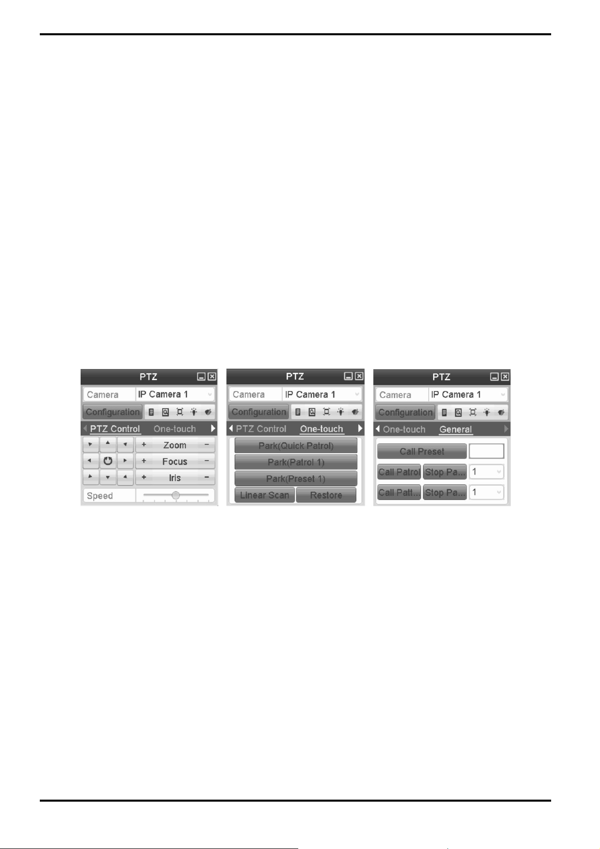
7.3. PTZ Control Panel
To enter the PTZ control panel, two ways are supported.
OPTION 1:
In the PTZ settings interface, click the “PTZ” button on the lower-right corner which is next to the Back button.
OPTION 2:
In the Live View mode, you can press the “PTZ Control” button on the remote control, or choose the “PTZ Control”
icon, or select the “PTZ” option in the right-click menu.
Click the “Configuration” button on the control panel, and you can enter the “PTZ” Settings interface.
NOTE: In PTZ control mode, the PTZ panel will be displayed when a mouse is connected with the device. If no
mouse is connected, the “PTZ” icon appears in the lower-left corner of the window, indicating that this camera is
in PTZ control mode.
English
Page 45

8. Recording Settings
8.1. Configuring Parameters
By configuring the parameters you can define the parameters which affect the image quality, such as the
transmission stream type, the resolution and so on.
Before you start:
1. Make sure that the HDD has already been installed. If not, please install a HDD and initialise it. (Menu> HDD>
General)
2. Check the storage mode of the HDD.
1) Click “Advanced” to check the storage mode of the HDD.
2) If the HDD mode is “Quota”, please set the maximum recording capacity. For detailed information, see the
Chapter “Configuring the Quota Mode”.
3) If the HDD mode is “Group”, you should set the HDD group. For detailed information, see the Chapter
“Configuring the HDD Group for Recording”.
English
Page 46
Steps:
1. Enter the Recording settings interface to configure the recording parameters: Menu> Record> Parameters
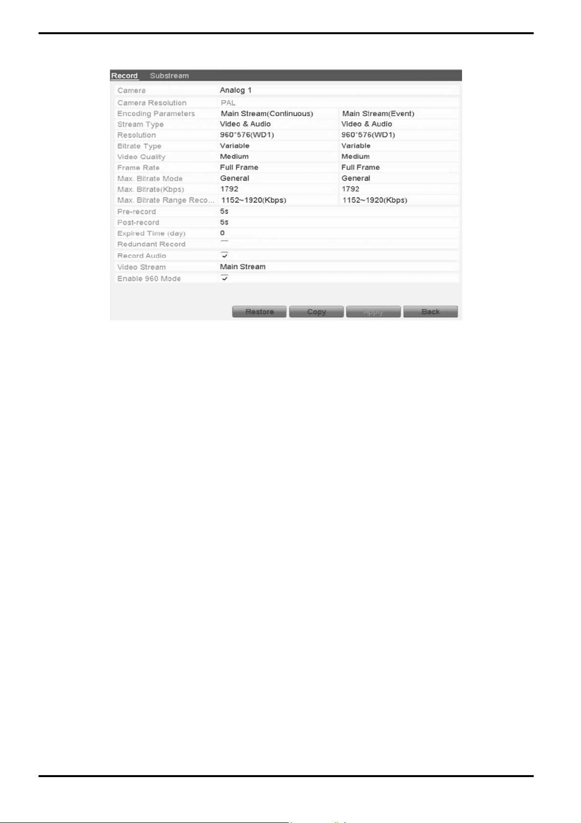
2. Parameters Setting for Recording:
Select the "Record" tab to configure the settings.
2) Select a camera number in the camera dropdown list.
You can configure the stream type, the resolution, the video quality and other parameters on demand for Main
Stream (Continuous) and Main Stream (Event) respectively.
The Input Resolution of the camera connected will be displayed in the live view for 5 seconds when the camera is
connected, or the DVR is powered on. The input resolution includes the resolution and frame rate of the camera,
e.g. 1080P/25.
3) You can configure the advantage parameters, including pre-record, post-record time, expired time, redundant
record (this option is only available when the HDD mode is Group) and whether you want to record audio.
- Pre-record: The time you set to record before the scheduled time or event. For example, when an alarm
triggered the recording at 10:00, if you set the pre-record time as 5 seconds, the camera records it at 9:59:55.
- Post-record: The time you set to record after the event or the scheduled time. For example, when an alarm
triggered the recording ends at 11:00, if you set the post-record time as 5 seconds, it records till 11:00:05.
- Expired Time: The expired time is the longest time for a record file to be kept in the HDD, if the deadline is
reached, the file will be deleted. You can set the expired time to 0, and then the file will not be deleted. The actual
keeping time for the file should be determined by the capacity of the HDD.
- Redundant Record: The redundant record is to decide whether you want the camera to save the record files on
the redundant HDD. You must configure the redundant HDD in the HDD settings. For detailed information, see
Chapter 5.8 "Configuring Redundant Recording".
- Record Audio: Check the checkbox of Record Audio to record the sound, otherwise the image will be recorded
without the sound.
- Video Stream: Main stream and sub-stream are selectable for recording. When you select sub-stream, you can
record for a longer time with the same storage space.
- Enable 960 Mode: The option is supported by analogue cameras. Enable the 960 mode to enable the WD1
resolution for the main stream, otherwise, the resolution supports up to 4CIF. And this option is not supported by
TVI cameras, while the WD1 resolution is available all the time.
4) Click "Apply" to save the settings.
5) You can copy the settings to other channels by clicking "Copy", if the setting can also be used for other
cameras.
English
Page 47

NOTE: You can copy the same settings to the cameras with the same signal. E.g., the channel No. 1-3 connect to
the TVI cameras, and the channel No.4 connects to an analogue camera, and then the settings of channel No. 1
can only be copied to channel 2 and 3.
3. Set encoding parameters for sub-stream.
1) Select the Substream tab.
2) Select a camera in the camera dropdown list.
3) Configure the parameters.
4) Click "Apply" to save the settings.
5) (Optional) If the parameters can also be used for other cameras, click "Copy" to copy the settings to other
channels.
8.2. Configuring the Recording Schedule
Set the recording schedule, and then the camera automatically starts/stops recording according to the
configured schedule.
Steps:
1. Enter the Recording Schedule interface: Menu> Record> Schedule
2. Configure the Recording Schedule:
1) Select “Record Schedule”.
English
Page 48

2) Choose the camera you want to configure.
3) Select the check box after the “Enable Schedule” item.
4) Click the “Edit” button or click on the colour icon under the “Edit” button and draw the schedule line on the
panel.
Edit the schedule:
I. In the message box, you can choose the day for which you want to set a schedule.
You can click the “(clock)” button to set the accurate time of the schedule.
II. To schedule an all-day recording, check the checkbox after the “All Day” item.
III. To arrange another schedule, leave the “All Day” checkbox blank and set the Start/End time.
NOTE: Up to 8 periods can be configured for each day. The time periods cannot overlap each other.
IV. Select the recording type in the dropdown list.
English
Page 49

NOTE:
- To enable Motion, Alarm, M | A (motion or alarm), M & A (motion and alarm) and VCA (Video Content Analysis)
triggered recording and capture, you must configure the motion detection settings, alarm input settings or VCA
settings as well. For detailed information, refer to Chapter 8.1, Chapter 8.2 and Chapter 8.5.
- The VCA settings are only available to IP cameras that are supporting these functions.
Repeat the above edit schedule steps to schedule the recording for other days in the week. You can click “Copy”
to enter “Copy to interface” to copy the schedule settings to other days.
V. Click “Apply” in the Recording Schedule interface to save the settings.
Draw the schedule:
I. If you click on the colour icons, you can choose the schedule type as "Continuous" or "Event".
Descriptions of the colour icons are shown in the figure below.
English
Page 50

II. Click the “Apply” button to validate the settings.
3. (Optional) If the settings can also be used for other channels, click “Copy”, and then choose the channel to
which you want to copy.
4. Click “Apply” to save the settings.
8.3. Configuring the Motion Detection Recording
Follow the steps to set the motion detection parameters. In live view mode, once a motion detection event takes
place, the NVR/DVR can analyse it and perform many actions to handle it. Enabling the motion detection function
can trigger certain channels to start recording, or trigger full screen monitoring, audio warning, notifying the
surveillance center and so on. In this chapter, you can follow the steps to schedule a recording which is triggered
by the detected motion.
Please note: Only cameras using Grundig-1 protocol can be configured for motion recording with the NVR/DVR.
Cameras using Grundig-2, ONVIF or any other protocol need to be configured directly in the camera OSD.
Steps:
1. Enter the Motion Detection interface: Menu> Camera> Motion
2. Configure the Motion Detection:
1) Choose the camera you want to configure.
2) Check the checkbox after “Enable Motion Detection”.
3) Drag and draw the area for motion detection by mouse. If you want to set the motion detection for all the area
shot by the camera, click “Full Screen”. To clear the motion detection area, click “Clear”.
English
Page 51

4) Click “Settings”, and the message box for channel information will pop up.
5) Select the channels for which you want a motion detection event to trigger a recording.
6) Click “Apply” to save the settings.
7) Click “OK” to go back to the upper level menu.
8) Exit the Motion Detection menu.
3. Edit the Motion Detection Recording Schedule. For detailed information of schedule configuration, see
Chapter “Configuring the Recording Schedule”.
8.4. Configuring the Alarm Triggered Recording
Follow the procedure to configure the alarm triggered recording.
Steps:
1. Enter the Alarm setting interface: Menu> Configuration> Alarm
English
Page 52

2. Click the “Alarm Input” tab and set the alarm parameters.
1) Select the Alarm Input number and configure the alarm parameters.
2) Choose N.O (normally open) or N.C (normally closed) as the alarm type.
3) Check the checkbox at “Enable”.
4) Click on the “(cogwheel)” button next to “Settings”.
5) Choose the alarm triggered recording channel.
6) Check the checkboxes to select the channels.
7) Click “Apply” to save the settings.
8) Click “OK” to go back to the upper level menu.
Repeat the above steps to configure other alarm input parameters.
If the settings can also be applied to other alarm inputs, click “Copy” and choose the alarm input number.
3. Edit the Alarm triggered recording in the Recording Schedule setting interface. For detailed information about
the schedule configuration, see Chapter ”Configuring the Recording Schedule”.
English
Page 53

8.5. Configuring the Manual Recording
Follow the steps below to set the parameters for the manual recording. When using Manual Recording, you need
to manually cancel the recording. The manual recording is prior to the scheduled recording.
Steps:
1. Enter the Manual settings interface: Menu> Manual
2. Enable the Manual Recording:
1) Select “Record” on the left bar.
2) Click the status button in front of the camera number to change from “OFF” to “ON”.
3. Disable Manual Recordin:
Click the status button to change from “ON” to “OFF”.
NOTE: The “ON” written in green means that the channel is configured for the recording schedule. After
rebooting, all the manual recordings enabled will be canceled.
8.6. Configuring the Holiday Recording
Follow the steps to configure the recording schedule on holidays for that year as you may want to have a different
plan for recording on a holiday.
Steps:
1. Enter the Recording setting interface:
Menu> Record> Holiday
English
Page 54

2. Enabling the Edit Holiday schedule:
1) Click on the “(pen on a written sheet)” button to enter the “Edit “interface.
2) Check the checkbox after “Enable Holiday”.
3) Select “Mode” from the dropdown list.
There are three different modes for the date format to configure a holiday schedule.
4) Set the start and end date.
5) Click “Apply” to save the settings.
6) Click “OK” to exit the Edit interface.
3. Enter the Recording Schedule settings interface to edit the holiday recording schedule. For details, see
Chapter 6.2 “Configuring the Recording Schedule".
8.7. Configuring the Redundant Recording
This function is for redundant recording which means that saving the recording files, not only on the R/W HDD but
also on the redundant HDD, will effectively enhance the data safety and reliability.
Steps:
1. Enter the HDD Information interface: Menu> HDD
English
Page 55

2. Select the “HDD” and click on the “(pen on a written sheet)” button to enter the Local HDD Settings interface.
1) Set the HDD property to “R/W”.
2) Click “Apply” to save the settings.
3) Click “OK” to go back to the upper level menu.
NOTE: You must set the Storage mode in the HDD advanced settings to “Group” before you set the HDD property
to “Redundant”. For detailed information, please refer to Setting the HDD Property. There should be at least
another HDD which is in Read/Write status.
3. Enter the Recording setting interface: Menu> Record> Parameters
1) Select the “Record” tab.
2) Select the Camera you want to configure in the drop-down list.
3) Check the checkbox of “Redundant Record”.
4) Click “OK” to save the settings and to go back to the upper level menu.
Repeat the above steps for configuring other channels.
English
Page 56

8.8. Configuring the HDD Group for Recording
You can group the HDDs and save the recording files in a certain HDD group.
Steps:
1. Enter the HDD setting interface: Menu> HDD
2. Select “Advanced” on the left side menu.
Check whether the storage mode of the HDD is “Group”. If not, set it to “Group”. For detailed information, please
refer to Chapter “Managing a HDD Group”.
3. Select “General” in the left side menu.
4. Click on the “(pencil on a written sheet)” button to enter the editing interface.
5. Configuring the HDD group:
1) Choose a group number for the HDD group.
2) Click “Apply” and then in the pop-up message box, click “Yes” to save your settings.
3) Click “OK” to go back to the upper level menu.
Repeat the above steps to configure more HDD groups.
6. Choose the Channels for which you want to save the recording files in the HDD group.
1) Select “Advanced” on the left bar.
2) Choose a Group number in the dropdown list of “Record on HDD Group”.
3) Check the channels you want to save in this group.
4) Click “Apply” to save the settings.
English
Page 57

8.9. Files Protection
You can lock the recorded files or set the HDD property to Read-only to protect the recording files from being
overwritten.
Protect a file by locking the recording files:
Steps:
1. Enter Export setting interface: Menu> Export
2. Select the channels you want to investigate by checking the checkbox.
3. Configure the recording type, file type and start/end time.
4. Click “Search” to show the results.
5. Protect the recording files.
1) Find the recording files you want to protect, and then click on the “(open lock)” icon which will turn to a
“(closed lock)”, indicating that the file is locked.
NOTE: The recording files for which the recording is not completed yet cannot be locked.
2) Click on “(closed lock)” to change it to “(open lock)” to unlock the file and the file will not be protected
anymore.
English
Page 58

Protect a file by setting the HDD property to “Read-only”:
Steps:
1. Enter the HDD setting interface: Menu> HDD
2. Click on the “(pencil on a written sheet)” button to edit the HDD you want to protect.
NOTE: To edit the HDD property, you need to set the storage mode of the HDD to “Group”. See Chapter “Managing
a HDD Group”.
3. Set the HDD property to “Read-only”.
4. Click “OK” to save the settings and to go back to the upper level menu.
NOTE:
- You cannot save any files on a Read-only HDD. If you want to save files on the HDD, change the property to
“R/W”.
- If there is only one HDD and it is set to “Read-only”, the NVR/DVR cannot record any files. Only live view mode
is then available.
- If you set the HDD to “Read-only” when the NVR/DVR is saving files on it, then the file will be saved on the next
R/W HDD. If there is only one HDD, the recording will be stopped.
English
Page 59

9. Playback
9.1. Playing Back Recording Files
9.1.1. Playing Back by Channel
This explains how to play back the recorded video files of a specific channel in the live view mode. The Channel
switch is supported.
Instant playback by channel:
Steps:
Choose a channel in live view mode using the mouse and click the “(backward arrow on an SD card)” button in the
quick setting toolbar.
NOTE: In the instant playback mode, only the recording files recorded during the last five minutes on this channel
will be played back.
All-day Playback by channel:
1. Enter the All-day Playback interface.
OPTION 1:
Right-click on the live view window and the live view toolbar appears at the bottom of the screen. Then click the
icon “(backward arrow on a photo negative)” on the live view toolbar to enter the Playback interface.
English
Page 60
NOTE: Pressing numerical buttons will switch the playback to the corresponding channels during the playback
process.
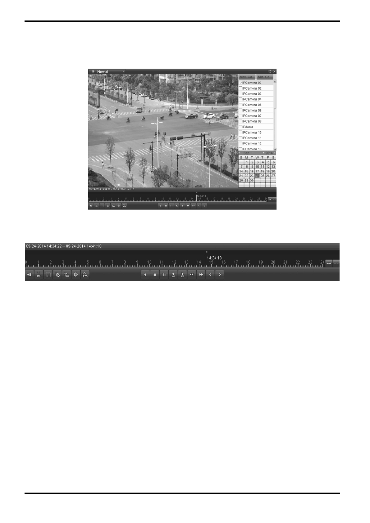
2. Playback management:
The toolbar in the bottom part of the Playback interface can be used to control the playing progress.
Click on the channel(s) to execute simultaneous playback of multiple channels.
NOTE: The writing “09-24-2014 14:34:22 – 09-24-2014 14:41:10” indicates the start/end time of the recording.
English
Page 61

NOTE: For the Playback progress bar: use the mouse to click any point of the progress bar or drag the progress
bar to locate special frames.
9.1.2. Playing Back by Time
This function plays back video files recorded in a specified time duration. Multi-channel simultaneous playback
and channel switch are supported.
Steps:
1. Enter the playback interface: Menu> Playback
2. Check the checkbox of the channel(s) in the channel list and then double-click to select a date on the
calendar.
English
Page 62
NOTE: If there are recording files for that camera in that day, in the calendar, the icon for that day is displayed as
a number in a dark coloured square. Otherwise it is displayed as a number in a light coloured square.
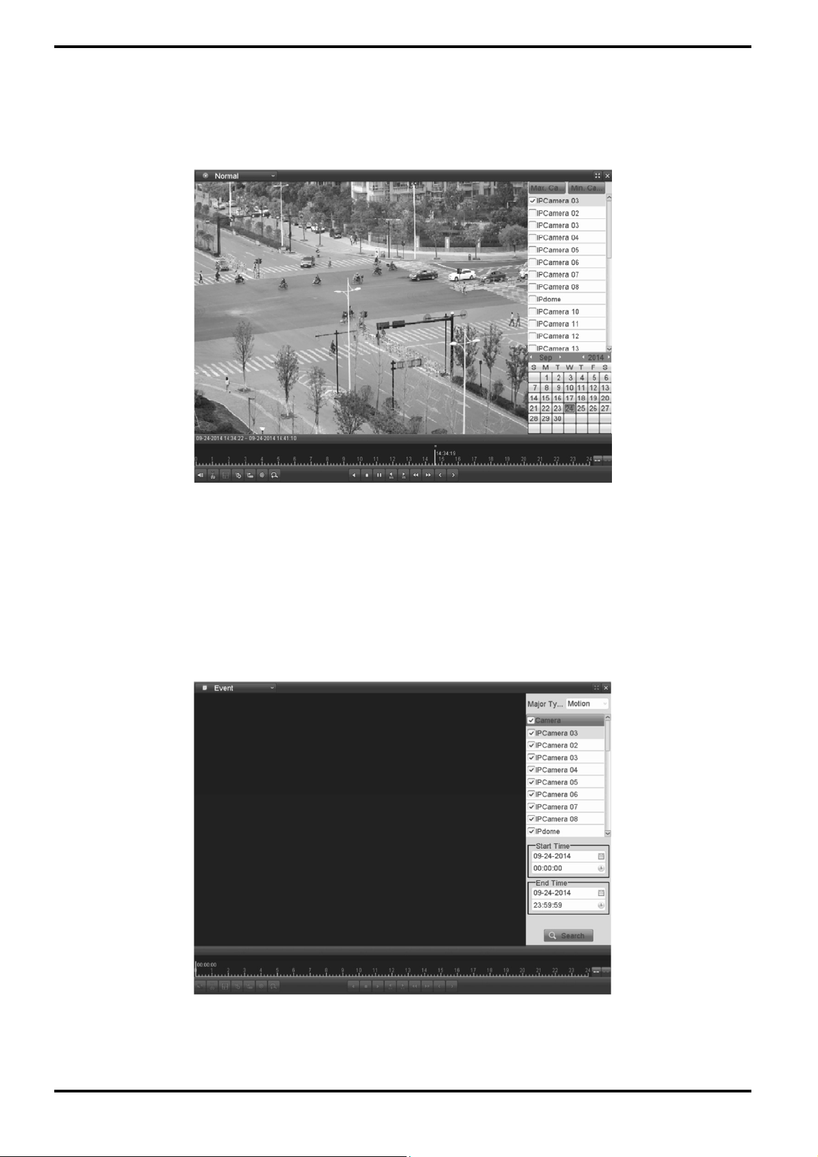
In the Playback interface:
The toolbar in the bottom part of Playback interface can be used to control the playing process.
9.1.3. Playing Back by Event Search
This function plays back the recording files on one or several channels searched out by the restricting event type
(e.g. alarm input and motion detection).
Steps:
1. Enter the Playback interface: Menu> Playback
2. Select “Event” in the drop-down list on the top-left side.
3. Select “Alarm Input”, “Motion” or “VCA” as the event type, edit the Start time and End time.
NOTE: Here we take playback by motion as the example.
English
Page 63
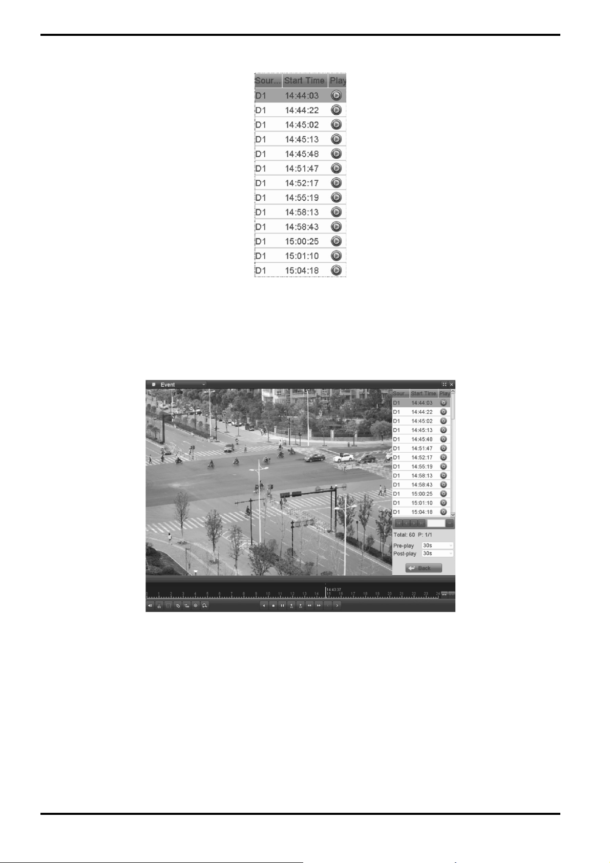
4. Click the “Search” button to get the search result information. You may refer to the right-side bar for the
result.
5. Click the “>” button to play back the file.
You can click the “Back” button to go back to the search interface.
NOTE: Pre-play and post-play can be configured.
6. Playback interface:
The toolbar in the bottom part of Playback interface can be used to control the playing process.
English
Page 64

This function plays back video files recorded in a specified time duration. Multi-channel simultaneous playback
and channel switch are supported.
Steps:
1. Enter the playback interface: Menu> Playback
2. Check the checkbox of the channel(s) in the channel list and then double-click to select a date on the
calendar.
9.1.4. Playing Back by Tag
The Video tag allows you to record related information like people and location at a certain time point during
playback. You are also allowed to use video tag(s) to search for recording files and position a time point.
Before playing back by tag:
1. Enter the Playback interface: Menu> Playback
2. Search and play back the recording file(s). Refer to Chapter 6.1.1 for detailed information about searching and
playback of the recording files.
English
Page 65

Click the “(flag with a plus)” button to add a default tag.
Click the “(flag with dots)” button to add a customised tag and input a tag name.
NOTE: Max. 64 tags can be added to a single video file.
3. Tag management:
Click the “(cogwheel)” button to check, edit and delete tag(s).
Steps:
1. Select “Tag” from the drop-down list in the Playback interface.
2. Choose channels, edit the start time and end time, and then click “Search” to enter the Search Result
interface.
NOTE: You can enter the keyword in the textbox next to “Keyword” to search the tag on your command.
English
Page 66

3. Click the “>” button to play back the file.
You can click the “Back” button to go back to the search interface.
NOTE: Pre-play and post-play can be configured.
9.1.5. Playing Back by System Logs
This function plays back recording file(s) associated with channels after searching the system logs.
Steps:
1. Enter the Log Information interface: Menu> Maintenance> Log Information
2. Click the “Log Search” tab to enter the Playback by System Logs.
Set the search time and type and click the “Search” button.
English
Page 67

3. Choose a log with the recording file and click the “>” button to enter the Playback interface.
NOTE: If there is no recording file at the time point of the log, the message box “No result found” will pop up.
4. Playback interface:
The toolbar in the bottom part of the Playback interface can be used to control the playing process.
English
Page 68

9.1.6. Playing Back the External File
Perform the following steps to look up and play back files in the external devices.
Steps:
1. Enter the Tag Search interface: Menu> Playback
2. Select the External File in the drop-down list on the top-left side. The files are listed in the right-side list. You
can click the “Refresh” button to refresh the file list.
3. Select and click the “>” button to play it back. And you can adjust the playback speed by clicking “>>” and “<<”.
9.2. Auxiliary Functions of Playback
9.2.1. Playing Back Frame by Frame
This function plays the video files frame by frame for checking the image details of the video when abnormal
events happen.
Steps:
Go to the Playback interface.
If you choose the playback of the recording file: click the button “<<” until the speed changes to Single frame and
one click on the playback screen represents the playback of one frame.
If you choose reverse playback of the recording file: click the button “<<” until the speed changes to Single frame
and one click on the playback screen represents the reverse playback of one frame.
It is also feasible to use the button “II” in the toolbar.
English
Page 69

9.2.2. Digital Zoom
Steps:
1. Click the “(magnifying glass with a plus)” button on the playback control bar to enter the Digital Zoom
interface.
2. Use the mouse to draw a red rectangle and the image within it will be enlarged up to 16 times.
3. Right-click on the image to exit the digital zoom interface.
9.2.3. Reverse the Playback of Multi-channel
You can play back the recording files of multi-channel reversely. Up to 16-ch (with 1280*720 resolution)
simultaneous reverse playback is supported; up to 4-ch (with 1920*1080P resolution) simultaneous reverse
playback is supported and up to 1-ch (with 2560*1920 resolution) reverse playback is supported.
Steps:
1. Enter the Playback interface: Menu> Playback
2. Check more than one checkbox to select multiple channels and click to select a date on the calendar.
3. Click “<” to play back the recording files reversely.
English
Page 70
10. Backup
10.1. Backing up the Recording Files
10.1.1. Backing up by Normal Video Search
The recording files can be backed up to various devices, such as USB devices (USB flash drives, USB HDDs, USB
writer) and SATA device.
Backup using USB flash drives and USB HDDs:
Steps:
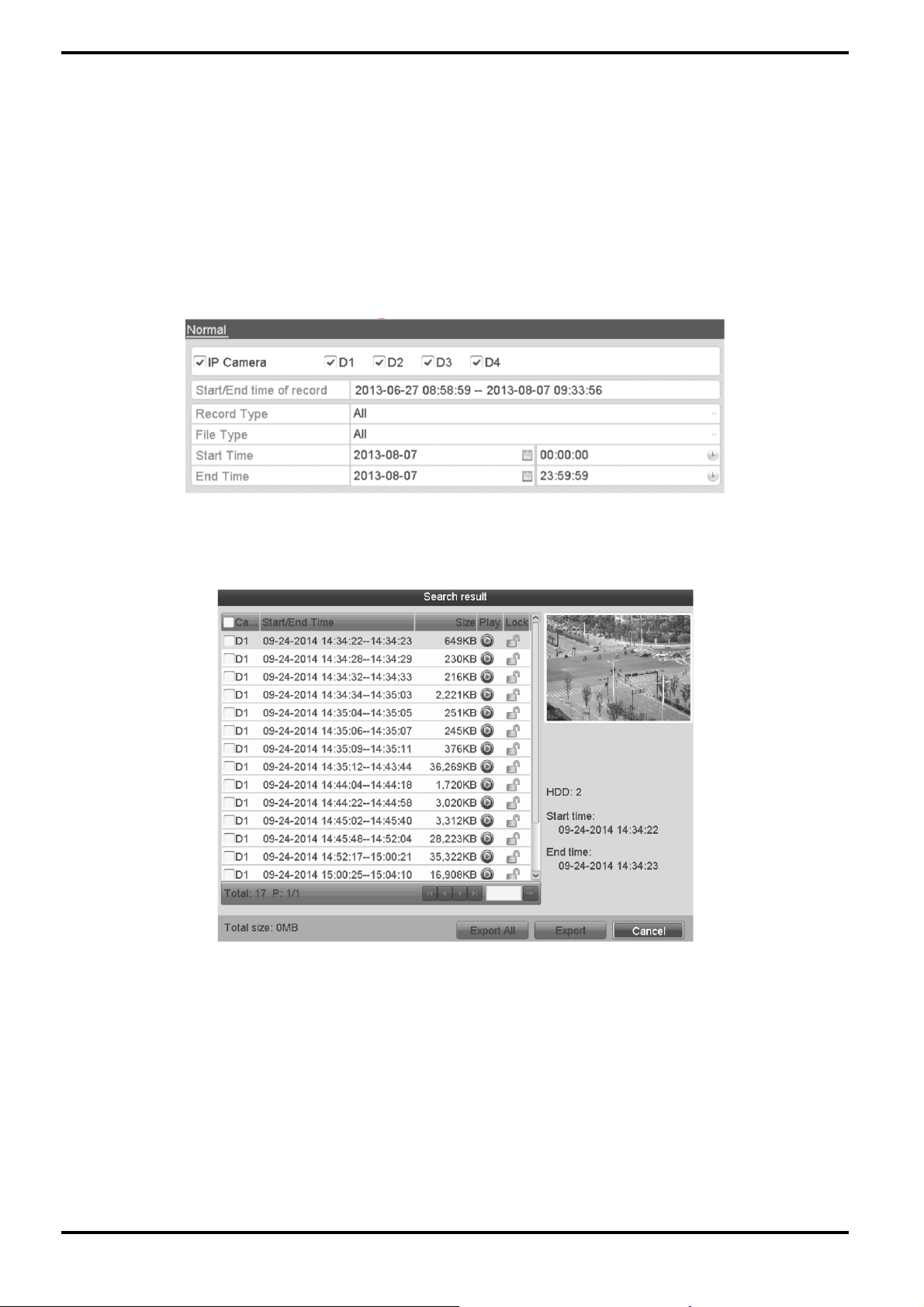
1. Enter the Export interface: Menu> Export> Normal
2. Set the search condition and click the “Search” button to enter the search result interface.
3. Select the recording files you want to back up. Click ”>” to play the recording file if you want to check it. Check
the checkbox in front of the recording files you want to back up.
NOTE: The size of the currently selected files is displayed in the lower-left corner of the window.
English
Page 71

4. Export:
Click the “Export All” button to export all the recording files. Or you can select the recording files you want to
back up, and click the “Export” button to enter the Export interface.
NOTE: If the inserted USB device is not recognised:
- Click the Refresh button.
- Reconnect device.
- If this does not work, this device might not be supported or defect.
You can also format USB flash drives or USB HDDs via the device.
Stay in the Exporting interface until all recording files are exported and until the pop-up message box “Export
finished” appears.
5. Check the backup result:
Choose the recording file in the Export interface and click the button “>” to check it.
NOTE: The Player player.exe will be exported automatically during the recording file export.
English
Page 72

Backup using the USB DVD writer and SATA device:
Steps:
1. Enter the Export interface: Menu> Export> Normal
2. Set the search condition and click the “Search” button to enter the search result interface.
3. Select the recording files you want to back up. Click the “>” button to play the recording file if you want to
check it. Check the checkbox in front of the recording files that you want to back up.
NOTE: The size of the currently selected files is displayed in the lower-left corner of the window.
English
Page 73

4. Export:
Click the “Export” button and start the backup.
NOTE: If the inserted USB writer or SATA writer is not recognised:
- Click the “Refresh” button.
- Reconnect the device.
If this does not work, this device might not be supported or defect.
Stay in the Exporting interface until all recording files are exported and until the pop-up message box “Export
finished” appears.
5. Check the backup result. Choose the recording file in the Export interface and click the “>” button to check it.
10.1.2. Backing up by Event Search
This function backs up event-related recording files using USB devices (USB flash drives, USB HDDs, USB writer)
and/or a SATA device. Quick Backup and Normal Backup are supported.
Steps:
1. Enter the Export interface: Menu> Export> Event
1) Select “Alarm Input” from the dropdown list of “Event Type”.
2) Select the “Alarm Input No.” and “Time”.
3) Click “Search” button to enter the Search Result interface.
NOTE: Event types contain Alarm Input, Motion and VCA.
English
Page 74

2. Select the recording files to export.
1) Clicking the “Quick Export” button will export the recording files of all channels triggered by the selected
alarm input.
2) Click the “Details” button to view detailed information of the recording file, e.g. start time, end time, file size,
etc.
English
Page 75

3. Export:
Click the “Export All” button to export all the recording files. Or you can select the recording files you want to
back up, and click the “Export” button to enter the Export interface.
NOTE: If the inserted USB device is not recognised:
- Click the Refresh button.
- Reconnect the device.
- If this does not work, this device might not be supported or defect.
You can also format the USB flash drive or the USB HDDs via the device.
Stay in the Exporting interface until all recording files are exported and until the pop-up message “Export
finished” appears.
4. Check the backup result.
NOTE: The Player player.exe will be exported automatically during recording file export.
English
Page 76

10.1.3. Backing up Video Clips
You may also select video clips to export directly during Playback, using USB devices (USB flash drives, USB
HDDs, USB writer) or a SATA writer.
Steps:
1. Enter the Playback interface:
Please refer to Chapter 6.1 Playing Back Recording Files.
2. During playback, use the buttons “(scissors)” and “(scissors with a tick)” in the playback toolbar to start or
stop clipping the recording file(s).
3. Click the “(disc)” symbol to save the video clips. Otherwise the promption for saving clips will pop up when you
quit the playback interface.
NOTE: A maximum of 30 clips can be selected for each channel.
English
Page 77
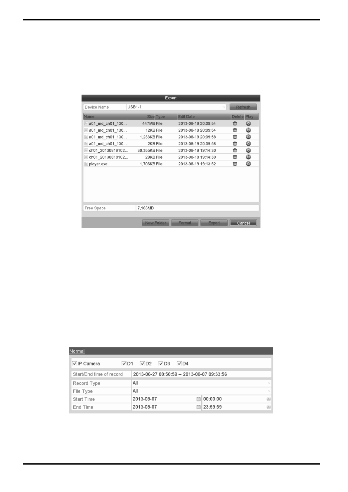
4. Export:
Click on the “Export” button and start the backup.
NOTE: If the inserted USB device is not recognised:
- Click the “Refresh” button.
- Reconnect the device.
- If this does not work, this device might not be supported or defect.
You can also format an USB flash drive or USB HDDs via the device.
Stay in the Exporting interface until all recording files are exported and the pop-up message “Export finished”
appears.
5. Check the backup result.
NOTE: The Player player.exe will be exported automatically during the recording file export.
10.2. Managing the Backup Devices
Management of the USB flash drives and USB HDDs:
Steps:
1. Enter the Search Result interface of the recording files: Menu> Export> Normal
Set the search condition and click the “Search” button to enter the Search Result interface.
NOTE: At least one channel needs to be selected.
English
Page 78
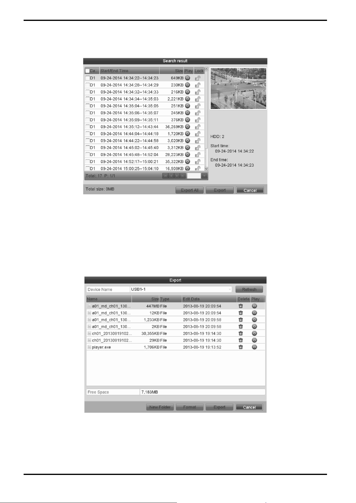
2. Click on the “Export All” button to export all the recording files.
Or you can select recording files you want to back up, and click the “Export” button to enter the Export interface.
NOTE: At least one recording file needs to be selected.
3. Backup device management:
Click on the “New Folder” button if you want to create a new folder on the backup device. Select a recording file
or folder on the backup device and click the “(red bin)” button if you want to delete it. Select a recording file on
the backup device and click the “>” button to play it. Click the “Format” button if you like to format the backup
device.
NOTE: If the inserted USB device is not recognised:
- Click the “Refresh” button.
- Reconnect the device.
- If this does not work, this device might not be supported or defect.
English
Page 79
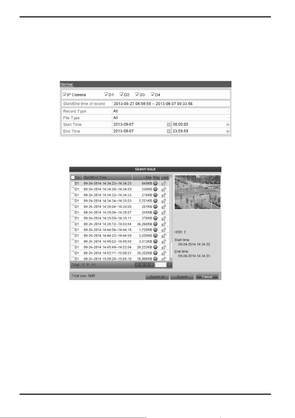
Management of USB DVD-R/W writers:
NOTE: DVD-R/W is only supported by GRY-K4416A.
1. Enter the Search Result interface of the recording files:
Menu> Export> Normal
Set the search condition and click the “Search” button to enter the Search Result interface.
NOTE: At least one channel shall be selected.
2. Select the recording files you want to back up. Click the “Export All” button to export all the recording files. Or
you can select the recording files you want to back up, and click the “Export” button to enter the Export interface.
NOTE: At least one recording file shall be selected.
English
Page 80

3. Backup device management:
Click the “Erase” button if you want to erase the files from a re-writable CD/DVD.
NOTE: Please note the following:
- There must be a re-writable CD/DVD when you make this operation.
- If the inserted USB writer or DVD-R/W is not recognised:
> Click the “Refresh” button.
> Reconnect the device.
> If this does not work, this device might not be supported or defect.
11. Alarm Settings
11.1. Setting the Motion Detection Alarm
Steps:
1. Enter the Motion Detection interface of the Camera Management and choose a camera you want to set up the
motion detection for: Menu> Camera> Motion
2. Set up the detection area and sensitivity. Tick “Enable Motion Detection”, and use the mouse to draw
detection area(s) and drag the sensitivity bar to set the sensitivity.
NOTE: By default, the motion detection is enabled and configured in full screen. Click the “(cogwheel)” button and
set the alarm response actions.
English
Page 81

3. Click the “Trigger Channel” tab and select one or more channels which will start to record or turn to fullscreen monitoring when the motion alarm is triggered, and click “Apply” to save the settings.
4. Set up the arming schedule of the channel:
1) Select the “Arming Schedule” tab to set the arming schedule of handling actions for the motion detection.
2) Choose one day of a week and up to eight time periods can be set within each day.
3) Click “Apply” to save the settings.
NOTE: Time periods shall not be repeated or overlapped.
5. Click the “Handling” tab to set up alarm response actions of the motion alarm (please refer to Chapter
“Setting Alarm Response Actions”).
6. If you want to set the motion detection for another channel, repeat the above steps or just click “Copy” in the
Motion Detection interface to copy the above settings to it.
English
Page 82
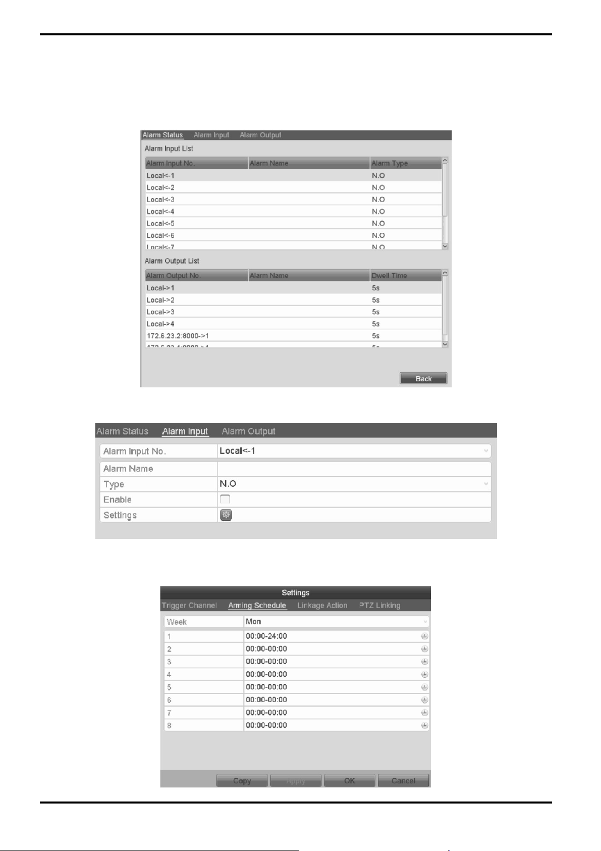
11.2. Setting the Sensor Alarms
Here you can set the handling action of an external sensor alarm.
Steps:
1. Enter the Alarm Settings of System Configuration and select an alarm input: Menu> Configuration> Alarm
Select the “Alarm Input” tab to enter the Alarm Input Settings interface.
2. Set up the handling action of the selected alarm input.
Check the “Enable” checkbox and click the “Settings” button to set up its alarm response actions.
3. Select the “Trigger Channel” tab and select one or more channels which will start to record or turn to fullscreen monitoring when an external alarm is input, and click “Apply” to save the settings.
4. Select the “Arming Schedule” tab to set the arming schedule of handling actions.
English
Page 83

Choose one day of a week and max. eight time periods can be set within each day, and click “Apply” to save the
”
settings.
NOTE: Time periods shall not be repeated or overlapped.
Repeat the above steps to set up the arming schedule for other days of a week. You can also use the “Copy”
button to copy an arming schedule to other days.
5. Select the “Linkage Action” tab to set up alarm response actions for the alarm input (please refer to Chapter
“Setting Alarm Response Actions”).
6. If necessary, select the “PTZ Linking” tab and set the PTZ linkage of the alarm input. Set the PTZ linking
parameters and click “OK” to complete the settings of the alarm input.
NOTE: Please check whether the PTZ or speed dome supports PTZ linkage.
One alarm input can trigger presets, patrol or pattern of more than one channel. But presets, patrols and
patterns are exclusive.
7. If you want to set the handling action of another alarm input, repeat the above steps. Or you can click the “Copy
button on the Alarm Input Setup interface and check the checkbox of alarm inputs to copy the settings to them.
English
Page 84

11.3. Detecting a Video Tampering Alarm
This function is for triggering an alarm when the lens is covered and to take alarm response action(s).
Please note: This function is only supported by cameras using the Grundig-1 protocol.
Steps:
1. Enter the Video Tampering interface of the Camera Management and select a channel you want to detect the
video tampering for: Menu> Camera> Video Tampering
2. Set the video tampering handling action of the channel.
Check the checkbox of “Enable Video Tampering Detection”. Drag the sensitivity bar to set a proper sensitivity
level. Use the mouse to draw an area where you want to detect video tampering. Click the “(cogwheel)” button to
set up the handling action of video tampering.
3. Set the arming schedule and alarm response actions of the channel.
1) Click the “Arming” Schedule tab to set the arming schedule of the handling actions.
2) Choose one day of a week and max. eight time periods can be set within each day.
3) Click “Apply” button to save the settings.
NOTE: Time periods shall not be repeated or overlapped.
4. Select the “Linkage Action” tab to set up alarm response actions for the video tampering alarm (please refer to
“Chapter Setting Alarm Response Actions”).
5. Click the “OK” button to complete the video tampering settings of the channel.
English
Page 85

11.4. Detecting a Video Loss Alarm
This function is for detecting video loss of a channel and taking alarm response action(s).
Steps:
1. Enter the “Video Loss” interface of the Camera Management and select a channel you want to detect:
Menu> Camera> Video Loss
2. Set up the handling action for video loss.
Check the checkbox of “Enable Video Loss Alarm”, and click the “(cogwheel)” button to set up the handling action
of video loss.
3. Set up the arming schedule of the handling actions.
1) Select the “Arming Schedule” tab to set the channel’s arming schedule.
2) Choose one day of a week and up to eight time periods can be set within each day.
3) Click “Apply” button to save the settings.
NOTE: Time periods shall not be repeated or overlapped.
4. Select the “Linkage Action” tab to set up the alarm response action of video loss (please refer to Chapter
“Setting Alarm Response Actions”).
5. Click the “OK” button to complete the video loss settings of the channel.
English
Page 86

11.5. Handling an Exceptions Alarm
The Exception Settings refer to the handling action of various exceptions, e.g.
- HDD Full: The HDD is full.
- HDD Error: Writing HDD error or unformatted HDD.
- Network Disconnected: Disconnected network cable.
- IP Conflicted: Duplicated IP address.
- Illegal Login: Incorrect user ID or password.
- Record Exception: No space for saving recorded files.
11.6. Setting Alarm Response Actions
Alarm response actions will be activated when an alarm or exception occurs, including Event Hint Display, Full
Screen Monitoring, Audible Warning (buzzer), Notify Surveillance Center, Upload Picture to FTP, Trigger Alarm
Output and Send Email.
Event Hint Display:
When an event or exception happens, a hint can be displayed on the lower-left corner of the live view image. And
you can click on the hint icon to check the details. Furthermore, the event to be displayed is configurable.
Steps:
1. Enter the Exception settings interface: Menu> Configuration> Exceptions
2. Check the checkbox of “Enable Event Hint”.
English
Page 87

3. Click the “(cogwheel)” button to set the type of event to be displayed in the image.
4. Click the “OK” button to finish the settings.
Full Screen Monitoring:
When an alarm is triggered, the local monitor (VGA and HDMI monitor) displays in full screen the video image
from the alarming channel configured for full screen monitoring.
If the alarms are triggered simultaneously in several channels, their full-screen images will be switched at an
interval of 10 seconds (default dwell time). A different dwell time can be set by going to Menu> Configuration>
Live View> Full Screen Monitoring Dwell Time.
Auto-switch will terminate once the alarm stops and you will be taken back to the Live View interface.
NOTE: You must select during the “Trigger Channel” settings the channel(s) you want to create the full screen
monitoring for.
Audible Warning:
Triggers an audible beep when an alarm is detected.
Notify Surveillance Center:
Sends an exception or alarm signal to the remote alarm host when an event occurs. The alarm host refers to the
PC installed via a Remote Client.
NOTE: The alarm signal will be transmitted automatically at detection mode when the remote alarm host is
configured. Please refer to Chapter “Configuring a Remote Alarm Host” for details of alarm host configuration.
English
Page 88

Email Linkage:
Send an email with alarm information to a user or users when an alarm is detected. Please refer to Chapter 9.2.9
for details of the Email configuration.
Trigger Alarm Output:
Triggers an alarm output when an alarm is triggered.
1. Enter the Alarm Output interface:Menu> Configuration> Alarm> Alarm Output
Select an alarm output and set the alarm name and dwell time. Click the “Schedule” button to set the arming
schedule of alarm output.
NOTE: If “Manually Clear” is selected in the dropdown list of Dwell Time, you can clear it only by going to Menu>
Manual> Alarm.
2. Set up the arming schedule of the alarm output.
Choose one day of a week and up to 8 time periods can be set within each day.
NOTE: Time periods shall not be repeated or overlapped.
English
Page 89

3. Repeat the above steps to set up the arming schedule of other days of a week. You can also use the “Copy”
button to copy an arming schedule to other days. Click the “OK” button to complete the video tampering settings
of the alarm output No.
4. You can also copy the above settings to another channel.
11.7. Triggering or Clearing an Alarm Output Manually
The sensor alarm can be triggered or cleared manually. If “Manually Clear” is selected in the dropdown list of the
dwell time of an alarm output, the alarm can be cleared only by clicking the “Clear” button in the following
interface.
Steps:
1. Select the alarm output you want to trigger or clear and make related operations for: Menu> Manual> Alarm
2. Click the “Trigger”/”Clear” button if you want to trigger or clear an alarm output.
3. Click the “Trigger All” button if you want to trigger all alarm outputs.
4. Click the “Clear All” button if you want to clear all alarm outputs.
English
Page 90

12. Network Settings
12.1. Configuring the General Settings
The network settings must be properly configured before you operate the NVR/DVR over the network.
Steps:
1. Enter the Network Settings interface: Menu> Configuration> Network
2. Select the “General” tab.
3. In the “General Settings” interface, you can configure the following settings: Working Mode, NIC Type, IPv4
Address, IPv4 Gateway, MTU and DNS Server. If the DHCP server is available, you can click the checkbox of
“DHCP” to automatically obtain an IP address and other network settings from that server.
4. After having configured the general settings, click the “Apply” button to save the settings.
12.2. Configuring the Advanced Settings
12.2.1. Configuring the PPPoE Settings
Your NVR/DVR also allows access by Point-to-Point Protocol over Ethernet (PPPoE).
Steps:
1. Enter the “Network Settings” interface: Menu> Configuration> Network
2. Select the “PPPoE” tab to enter the PPPoE Settings interface.
3. Check the “Enable PPPoE” checkbox to enable this feature.
4. Enter the “User Name”, and “Password” for PPPoE access.
NOTE: The User Name and Password should be assigned by your ISP.
5. Click the “Apply” button to save and exit the interface.
6. After successfully finishing the settings, the system asks you to reboot the device to enable the new settings,
and the PPPoE dial-up will be automatically connected after the reboot. You can go to Menu> Maintenance>
System Info> Network interface to view the status of the PPPoE connection. Please refer to Chapter “Viewing
System Information” for the PPPoE status.
12.2.2. Configuring the Extranet Access
You can choose the access to the device by DDNS through the settings on the “Extranet Access” menu.
English
Page 91

12.2.3. Configuring DDNS
If your NVR/DVR is set to use PPPoE as ist default network connection, you may set Dynamic DNS (DDNS) to be
used for network access. Prior registration with your ISP is required before configuring the system to use DDNS.
Steps:
1. Enter the Network Settings interface: Menu> Configuration> Network
2. Select the “Extranet Access” tab to enter the DDNS Settings interface.
3. Check the “Enable DDNS” checkbox to enable this feature.
4. Select “DDNS Type”. 4 different DDNS types are selectable: IPServer, DynDNS, PeanutHull and NO-IP.
- IPServer: Enter the “Server Address” for the IP Server.
- DynDNS:
1) Enter the “Server Address” for DynDNS (i.e. members.dyndns.org).
2) In the NVR/DVR Domain Name text field, enter the domain obtained from the DynDNS website.
3) Enter the “User Name” and “Password” registered on the DynDNS website.
- PeanutHull: Enter the “User Name” and “Password” obtained from the PeanutHull website.
English
Page 92

- NO-IP:
Enter the account information in the corresponding fields. Refer to the DynDNS settings.
1) Enter the “Server Address” for NO-IP.
2) In the NVR/DVR Domain Name text field, enter the domain obtained from the NO-IP website (www.no-ip.com).
3) Enter the “User Name” and “Password” registered on the NO-IP website.
5. Click the “Apply” button to save the settings. After setting all the required parameters for the DDNS, you can
view the connecting status of the device by checking the “Status” information.
12.2.4. Configuring the NTP Server
Ensure that the network connection of the PC (running FTP server) and the device is valid and correct. Run the
FTP server on the PC and copy the firmware into the corresponding directory of your PC.
NOTE: Refer to the user manual of the FTP server to set the FTP server on your PC and put the firmware file into
the directory as required.
Steps:
1. Enter the Network Settings interface: Menu> Configuration> Network
2. Select the “NTP” tab to enter the NTP Settings interface.
3. Check the “Enable NTP” checkbox to enable this feature.
4. Configure the following NTP settings:
- Interval: Time interval between the two synchronising actions with the NTP server. The unit is minute.
- NTP Server: IP address of the NTP server.
- NTP Port: Port of the NTP server.
5.Click the “Apply” button to save and exit the interface.
NOTE: The time synchronisation interval can be set from 1 to 10080 min, and the default value is 60min. If the
NVR/DVR is connected to a public network, you should use a NTP server that has a time synchronisation function,
such as the server at the National Time Center (IP Address: 210.72.145.44). If the NVR/DVR is setup in a more
customised network, the NTP software can be used to establish a NTP server used for time synchronisation.
English
Page 93
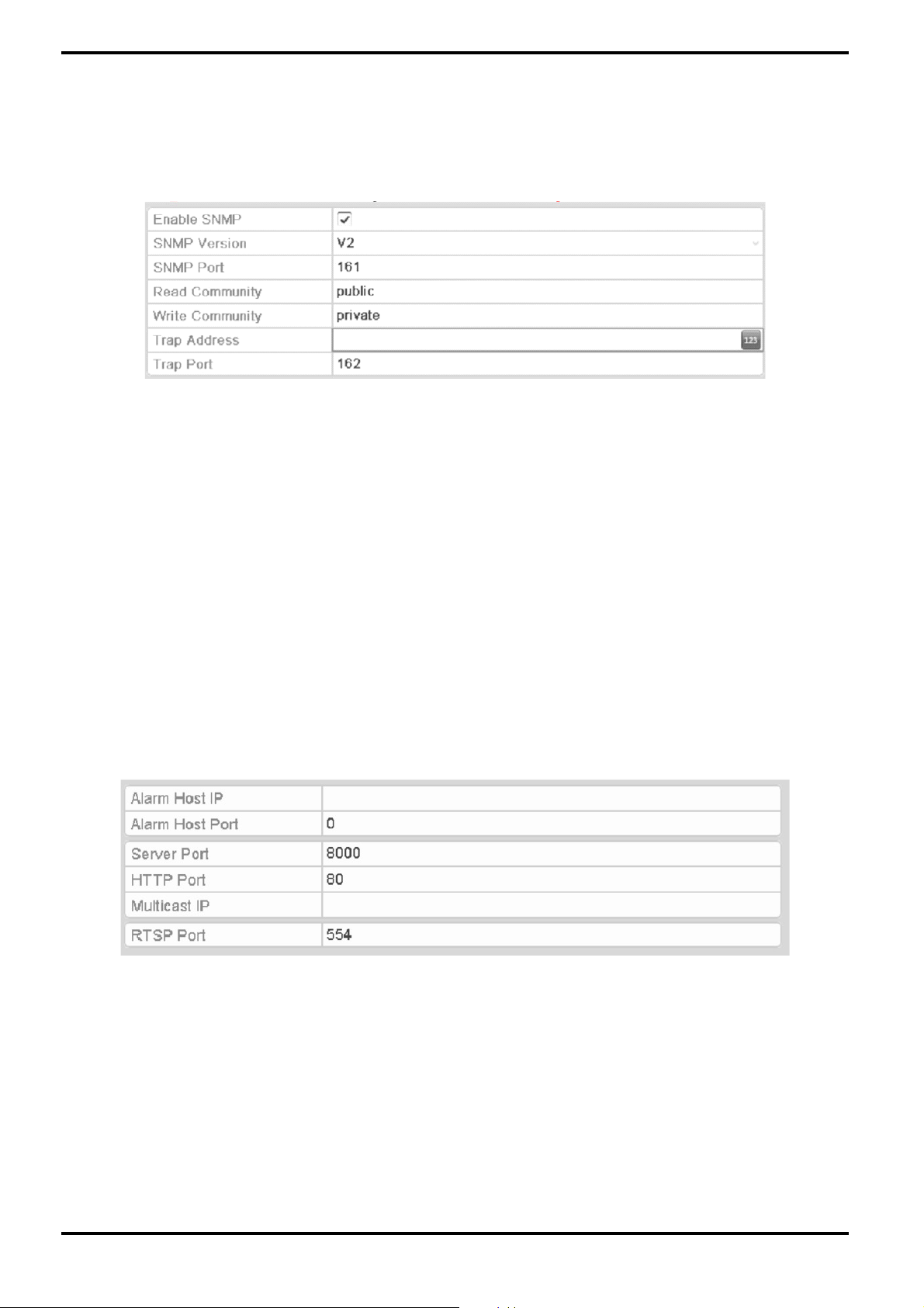
12.2.5. Configuring SNMP
You can use the SNMP protocol to get the device status and parameters related information.
Steps:
1. Enter the Network Settings interface: Menu> Configuration> Network
2. Select the “SNMP” tab to enter the SNMP Settings interface.
3. Check the “Enable SNMP” checkbox to enable this feature.
4. Configure the following SNMP settings:
- Trap Address: IP Address of the SNMP host.
- Trap Port: Port of the SNMP host.
5. Click the “Apply” button to save and exit the interface.
NOTE: Before setting the SNMP, please download the SNMP software and manage to receive the device
information via the SNMP port. By setting the Trap Address, the NVR/DVR is allowed to send the alarm event and
exception message to the surveillance center.
12.2.6. Configuring the Remote Alarm Host
With a remote alarm host configured, the NVR/DVR will send the alarm event or exception message to the host
when an alarm is triggered. The remote alarm host must have the Network Video Surveillance software installed.
Steps:
1. Enter the Network Settings interface: Menu> Configuration> Network
2. Select the “More Settings” tab to enter the More Settings interface, as shown below.
3. Enter the “Alarm Host IP” and “Alarm Host Port” in the text fields. The “Alarm Host IP” refers to the IP
address of the remote PC on which the Network Video Surveillance Software (SCMS) is installed, and
the “Alarm Host Port” must be the same as the alarm monitoring port configured in the software.
4. Click the “Apply” button to save and exit the interface.
English
Page 94

12.2.7. Configuring Multicast
The multicast can be configured to realise a live view for more than 128 connections through the network for the
device.
A multicast address spans the Class-D IP range of 224.0.0.0 to 239.255.255.255. It is recommended to use an IP
address ranging from 239.252.0.0 to 239.255.255.255.
Steps:
1. Enter the Network Settings interface: Menu> Configuration> Network
2. Select the “More Settings” tab to enter the More Settings interface
3. Set the “Multicast IP”. When adding a device to the Network Video Surveillance Software, the multicast
address must be the same as the NVR/DVR’s multicast IP.
4. Click the “Apply” button to save and exit the interface.
NOTE: The multicast function should be supported by the network switch to which the NVR/DVR is connected.
12.2.8. Configuring RTSP
The RTSP (Real Time Streaming Protocol) is a network control protocol designed for use in communication
systems to control streaming media servers.
Steps:
1. Enter the Network Settings menu: Menu> Configuration> Network
2. Select the “More Settings” tab to enter the “More Settings” menu.
3. Enter the RTSP port in the text field of “RTSP Service Port”. The default RTSP port is 554, and you can change
it according to different requirements.
4. Click the “Apply” button to save and exit the menu.
12.2.9. Configuring the Server and HTTP Ports
You can change the server and HTTP ports in the Network Settings menu. The default server port is 8000 and the
default HTTP port is 80.
Steps:
1. Enter the Network Settings interface: Menu> Configuration> Network
2. Select the “More Settings” tab to enter the “More Settings” interface.
3. Enter the new “Server Port” and “HTTP Port”.
4. Enter the Server Port and HTTP Port in the text fields. The default Server Port is 8000 and the HTTP Port is 80,
and you can change them according to different requirements.
5. Click the “Apply2 button to save and exit the interface.
NOTE: The Server Port should be set to the range of 2000-65535 and it is used for remote client software access.
The HTTP port is used for remote web browser access.
English
Page 95

12.2.10. Configuring Email
The system can be configured to send an Email notification to all designated users if an alarm or motion event is
detected or the administrator password is changed.
Before configuring the Email settings, the NVR/DVR must be connected to a local area network (LAN) that
maintains an SMTP mail server. The network must also be connected to either an intranet or the Internet
depending on the location of the e-mail accounts to which you want to send the notification.
Steps:
1. Enter the Network Settings interface: Menu> Configuration> Network
2. Set the “IPv4 Address”, “IPv4 Subnet Mask”, “IPv4 Gateway” and the “Preferred DNS Server” in the Network
Settings menu.
3. Click “Apply” to save the settings.
4. Select the “Email” tab to enter the Email Settings interface.
English
Page 96

5. Configure the following Email settings:
- Enable Server Authentication (optional): Check the checkbox to enable the server authentication feature.
- User Name: The user account of the sender’s Email for SMTP server authentication.
- Password: The password of the sender’s Email for SMTP server authentication.
- SMTP Server: The SMTP Server IP address or host name (e.g., smtp.yourprovider.com).
- SMTP Port No.: The SMTP port. The default TCP/IP port used for SMTP is 25.
- Enable SSL (optional): Click the checkbox to enable SSL if required by the SMTP server.
- Sender: The name of the sender.
- Sender’s Address: The Email address of the sender.
- Select Receivers: Select the receiver. Up to 3 receivers can be configured.
- Receiver: The name of the user to be notified.
- Receiver’s Address: The Email address of the user to be notified.
- Enable Attached Pictures: Check the checkbox of “Enable Attached Picture” if you want to send an email with
attached alarm images. The interval is the time of two adjacent alarm images. You can also set SMTP port and
enable SSL here.
- Interval: The interval refers to the time between two actions of sending attached pictures.
- E-Mail Test: Sends a test message to verify that the SMTP server can be reached.
6. Click the “Apply” button to save the Email settings.
7. You can click the “Test” button to test whether your Email settings work. The corresponding Attention
message box will pop up.
12.2.11. Configuring NAT
Two ways are provided for port mapping to realise the remote access via the cross-segment network, UPnP™ and
manual mapping.
UPnP™:
Universal Plug and Play (UPnP™) can permit the device to seamlessly discover the presence of other network
devices on the network and to establish functional network services for data sharing, communications, etc. You
can use the UPnP™ function to enable the fast connection of the device to the WAN via a router without port
mapping.
English
Page 97

Two ways are provided for port mapping to realise the remote access via the cross-segment network, UPnP™ and
manual mapping.
UPnP™:
Universal Plug and Play (UPnP™) can permit the device to seamlessly discover the presence of other network
devices on the network and to establish functional network services for data sharing, communications, etc. You
can use the UPnP™ function to enable the fast connection of the device to the WAN via a router without port
mapping.
Before you start:
If you want to enable the UPnP™ function of the device, you must enable the UPnP™ function of the router to
which your device is connected. When the network working mode of the device is set as multi-address, the
Default Route of the device should be in the same network segment as that of the LAN IP address of the router.
Steps:
1. Enter the Network Settings interface: Menu> Configuration> Network
2. Select the “NAT” tab to enter the port mapping interface.
English
Page 98

3. Check the checkbox next to “Enable UPnP” to enable UPnP™.
4. Select the “Mapping Type” from “Manual” or “Auto” in the drop-down list.
OPTION 1: Auto
If you select Auto, the Port Mapping items are read-only, and the external ports are going to be set by the router
automatically.
Steps:
1) Select “Auto” in the drop-down list of Mapping Type.
2) Click the “Apply” button to save the settings.
3) You can click the “Refresh” button to get the latest status of the port mapping.
OPTION 2: Manual
If you select “Manual” as the mapping type, you can edit the external port on your demand by clicking on the
“(pencil on a written sheet)” symbol to activate the External Port Settings dialogue box.
Steps:
1) Select “Manual” in the drop-down list of Mapping Type.
2) Click on the “(pencil on a written sheet)” symbol to activate the External Port Settings dialogue box.
Configure the external port No. For server port, http port, RTSP port and https port respectively.
NOTE:
- You can use the default port No., or change it according to your actual requirements.
- The External Port indicates the port No. For port mapping in the router.
- The value of the RTSP port No. Should be 554 or between 1024 and 65535, while the value of the other ports
should be between 1 and 65535 and the values must be different from each other. If multiple devices are
configured for the UPnP™ settings under the same router, the value of the port No. For each device should be
unique.
English
Page 99

3) Click the “Apply” button to save the settings.
4) You can click the “Refresh” button to get the latest status of the port mapping.
Manual Mapping:
If your router does not support the UPnP function, perform the following steps to map the port manually in an
easy way.
Before you start:
Make sure the router supports the configuration of the internal port and the external port in the interface of
Forwarding.
Steps:
1. Enter the Network Settings interface: Menu> Configuration> Network
2. Select the “NAT” tab to enter the port mapping interface.
3. Leave the “Enable UPnP” checkbox unchecked.
4. Click on the “(pencil on a written sheet)” symbol to activate the External Port Settings dialogue box. Configure
the external port No. For server port, http port, RTSP port and https port respectively.
NOTE: The value of the RTSP port No. Should be 554 or between 1024 and 65535, while the value of the other
ports should be between 1 and 65535 and the values must be different from each other. If multiple devices are
configured for the UPnP™ settings under the same router, the value of the port No. For each device should be
unique.
5. Click "OK” to save the setting for the current port and to return to the upper-level menu.
6. Click the “Apply” button to save the settings.
7. Enter the virtual server setting page of router; fill in the blank of the Internal Source Port with the internal
port value, the blank of External Source Port with the external port value, and other required contents.
NOTE: Each item should be corresponding with the device port, including server port, http port, RTSP port and
https port.
English
Page 100

NOTE: The above virtual server setting interface is for reference only, it may be different due to different router
manufacturers. Please contact the manufacturer of the router if you have any problems with setting the virtual
server.
12.3. Checking the Network Traffic
You can check the network traffic to obtain real-time information of the NVR/DVR such as linking status, MTU,
sending/receiving rate, etc.
Steps:
1. Enter the Network Traffic interface: Menu> Maintenance> Net Detect
2. You can view the sending rate and receiving rate information on the interface. The traffic data is going to be
refreshed every second.
12.4. Configuring the Network Detection
You can obtain the network connecting status of the NVR/DVR through the network detection function, including
network delay, packet loss, etc.
12.4.1. Testing the Network Delay and Packet Loss
Steps:
1. Enter the Network Traffic interface: Menu> Maintenance> Net Detect
2. Click the “Network Detection” tab to enter the Network Detection menu.
English
 Loading...