

Page 1
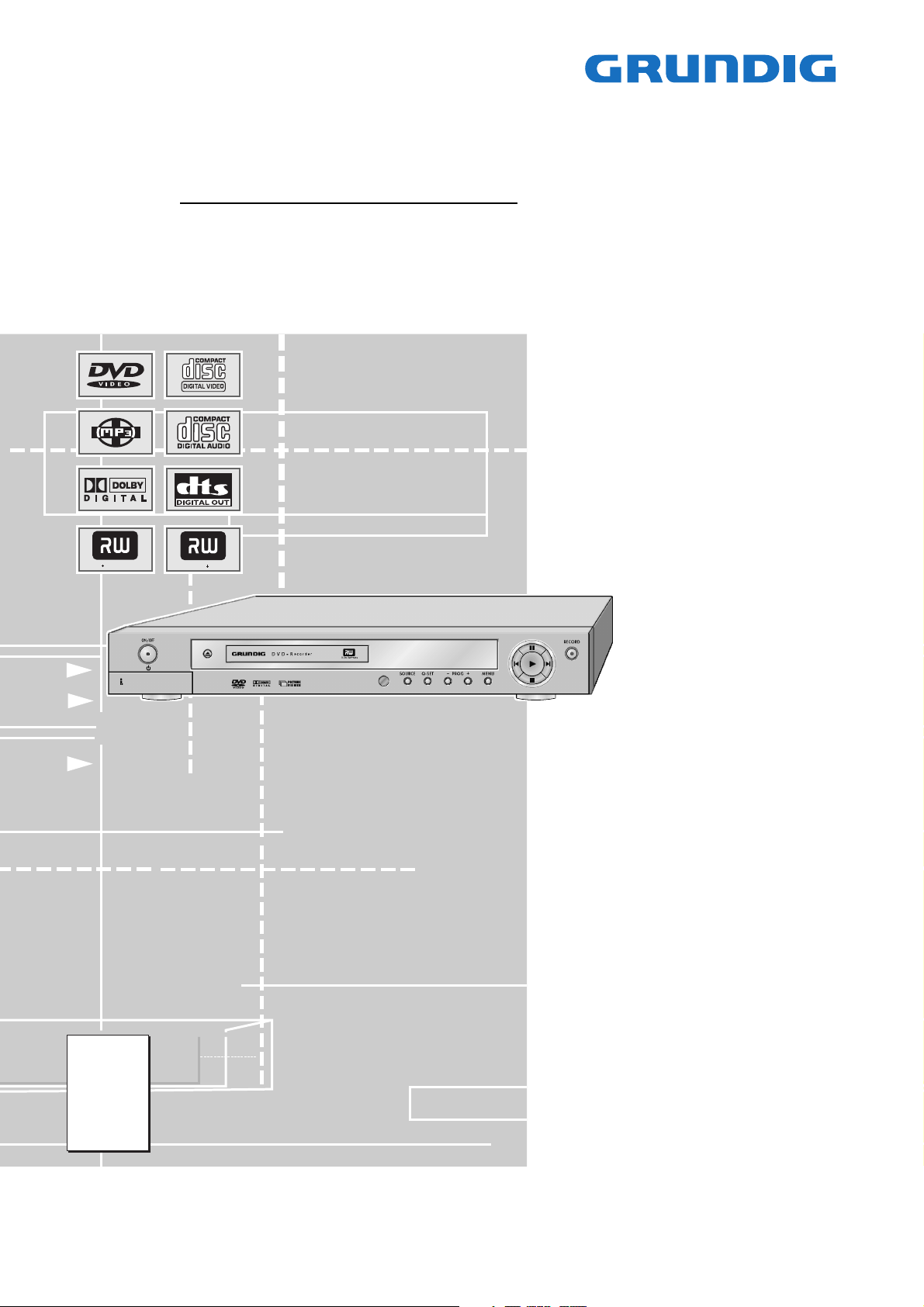
DVD Service Manual
GDR 5400/1
GMK2400
GDR 5400/2
GMK2500
GDR 5404
GMK3200
DVD R eWr itable
Zusätzlich erforderliche Unterlagen für den Komplettservice
Additionally required Service Documents for the Complete Service
DVD R
NUR FÜR INTERNEN GEBRAUCH
FOR INTERNAL USE ONLY
Service
Manual
Sicherheit
Safety
Materialnr./Part No.
720108000001
Materialnummer/Part Number 720100482500
Änderungen vorbehalten/Subject to alteration • Printed in Germany …
H-S41 1104 • 8002/8012 oUKIRL, 8003/8013 oD, 8005/8015
http://www.grundig.com
Page 2
GRUNDIG Service GDR 5400
Es gelten die Vorschriften und Sicherheitshinweise
gemäß dem Service Manual "Sicherheit", Materialnummer 720108000001, sowie zusätzlich die eventuell abweichenden, landesspezifischen Vorschriften!
Inhaltsverzeichnis
Seite
Allgemeiner Teil ................................. 1-2…1-32
Allgemeine Hinweise .................................................................... 1-2
Technische Daten ........................................................................ 1-3
Versions-Nummer (Software / Laufwerk) ..................................... 1-3
Software-Upgrade ........................................................................ 1-3
Servicehinweise ........................................................................... 1-4
Bedienhinweise ............................................................................ 1-5
Platinenabbildungen
und Schaltpläne ................................. 2-1…2-19
Verdrahtungsplan ......................................................................... 2-1
Netzteil ......................................................................................... 2-2
Hauptplatte ................................................................................... 2-4
– Netzteil ..................................................................................... 2-6
– Speicher ................................................................................... 2-7
– Interface ................................................................................... 2-8
– Konverter .................................................................................. 2-9
– Prozessor ............................................................................... 2-10
Buchsenplatte (Version 1) .......................................................... 2-11
– Video-/Audio-Anschlüsse ....................................................... 2-12
– Tuner, Frontend ..................................................................... 2-13
– Audio ...................................................................................... 2-14
– Scart ....................................................................................... 2-15
Buchsenplatte (Version 2) .......................................................... 2-16
– Video-/Audio-Anschlüsse ....................................................... 2-17
– Tuner, Frontend ..................................................................... 2-18
– Audio ...................................................................................... 2-19
– Scart ....................................................................................... 2-20
Bedieneinheit ............................................................................. 2-21
Keyboard.................................................................................... 2-21
DV-Platte .................................................................................... 2-22
AV-IN-Platte ............................................................................... 2-22
Oszillogramme ........................................................................... 2-23
The regulations and safety instructions shall be valid
as provided by the "Safety" Service Manual, part
number 720108000001, as well as the respective
national deviations.
Table of Contents
Page
General Section .................................. 1-2…1-60
General Notes .............................................................................. 1-2
Technical Data ............................................................................. 1-3
Version Numbers (Software / Loader) ......................................... 1-3
Software Upgrade ........................................................................ 1-3
Service Hints ................................................................................ 1-4
Operating Hints .......................................................................... 1-33
Layout of PCBs
and Circuit Diagrams ......................... 2-1…2-19
Wiring Diagram ............................................................................ 2-1
Power Supply ............................................................................... 2-2
Main Board ................................................................................... 2-4
– Power Supply ........................................................................... 2-6
– Memory .................................................................................... 2-7
– Interface ................................................................................... 2-8
– Converter ................................................................................. 2-9
– Processor ............................................................................... 2-10
Socket Board (Version 1) ........................................................... 2-11
– Video/Audio Sockets .............................................................. 2-12
– Tuner, Frontend ..................................................................... 2-13
– Audio ...................................................................................... 2-14
– Scart ....................................................................................... 2-15
Socket Board (Version 2) ........................................................... 2-16
– Video/Audio Sockets .............................................................. 2-17
– Tuner, Frontend ..................................................................... 2-18
– Audio ...................................................................................... 2-19
– Scart ....................................................................................... 2-20
Keyboard Control Unit ................................................................ 2-21
Keyboard .................................................................................... 2-21
DV Board ................................................................................... 2-22
AV-IN Board ............................................................................... 2-22
Oscillograms .............................................................................. 2-23
Explosionszeichnung
und Ersatzteillisten .............................. 3-1…3-2
Allgemeiner Teil
Allgemeine Hinweise
Vor dem Öffnen des Gehäuses den Netzstecker ziehen!
Achtung: ESD-Vorschriften beachten
Leitungsverlegung
Bevor Sie die Leitungen und insbesondere die Masseleitungen lösen,
muss die Leitungsverlegung zu den einzelnen Baugruppen beachtet
werden.
Nach erfolgter Reparatur ist es notwendig, die Leitungsführung wieder
in den werkseitigen Zustand zu versetzen um evtl. spätere Ausfälle
oder Störungen zu vermeiden.
Durchführen von Messungen
Bei Messungen mit dem Oszilloskop an Halbleitern sollten Sie nur
Tastköpfe mit 10:1 - Teiler verwenden. Außerdem ist zu beachten,
dass nach vorheriger Messung mit AC-Kopplung der Koppelkondensator des Oszilloskops aufgeladen sein kann. Durch die Entladung
über das Messobjekt können Bauteile beschädigt werden.
Messwerte und Oszillogramme
Bei den in den Schaltplänen und Oszillogrammen angegebenen
Messwerten handelt es sich um Näherungswerte!
Exploded Views
and Spare Parts Lists .......................... 3-1…3-2
General Section
General Notes
Before opening the cabinet disconnect the mains plug!
Attention: Observe the ESD safety regulations
Wiring
Before disconnecting any leads and especially the earth connecting
leads observe the way they are routed to the individual assemblies.
On completion of the repairs the leads must be laid out as originally
fitted at the factory to avoid later failures or disturbances.
Carrying out Measurements
When making measurements on semi-conductors with an oscilloscope, ensure that the test probe is set to 10:1 dividing factor. If the
previous measurement was made on AC input, please note that the
coupling capacitor in the oscilloscope will be charged. Discharge via
the item being checked can damage the components.
Measured Values and Oscillograms
The measured values given in the circuit diagrams and oscillograms
are approximates!
1 - 2
Page 3

GRUNDIG Service GDR 5400
Technische Daten
Netzspannung: .............................................110 – 240V~, 50/60Hz
Leistungsaufnahme:
– Betrieb: ............................................................................. ca. 35W
– Stand-by: ............................................................................... ≤4W
Umgebungstemperatur: ....................................... +10°C bis +35°C
Wiedergabe-Norm:
– PAL .................................................................... 50Hz, 625 Zeilen
– NTSC ................................................................. 60Hz, 525 Zeilen
Disc-Formate: ........................... DVD+R, DVD+RW, CD-R, CD-RW
Medien-Formate: ......................................... DVD-Video, Audio-CD,
Video-CD (VCD 1.0/1.1/2.0), S-Video-CD,
CD-ROM (DivX©Video, MP3, WMA, JPEG, Kodak Picture CD)
Laser: ...................................................................... Halbleiter-Laser
– Wellenlänge für DVD .......................................................... 650nm
– Wellenlänge für CD ............................................................ 780nm
Audio Format:
– Digital: ...................................... MPEG2/Dolby Digital, PCM, DTS
– Analog: ............................................... Stereoton, Dolby Pro Logic
Audio-Signal Analog:
– DVD: ...................................................... 48/96kHz 4Hz-22/44kHz
– Video-CD:................................................ 44,1kHz 4Hz-20kHz
– Audio-CD:................................................ 44,1kHz 4Hz-20kHz
– Rauschabstand (bei 1kHz): ................................................. ≤90dB
– Dynamik (bei 1kHz): ............................................................ ≤85dB
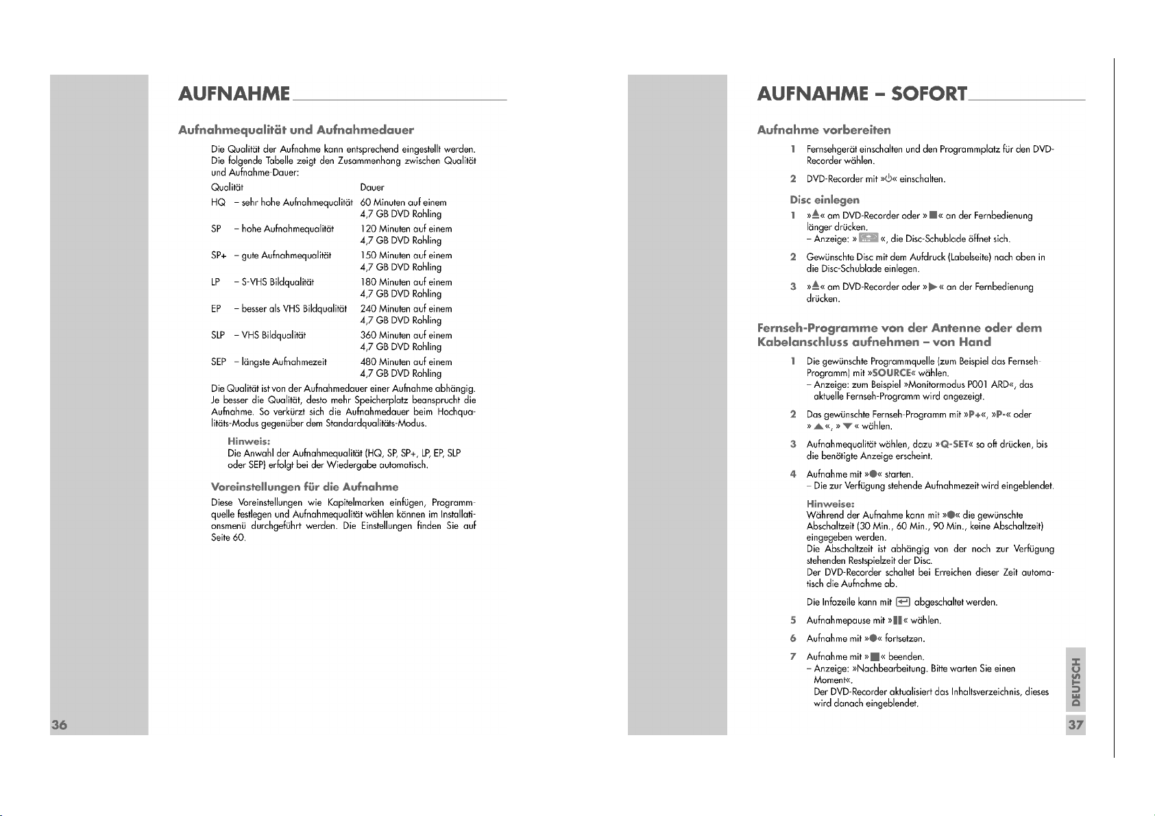
Aufnahmequalität und Dauer auf einem 4,7GB DVD-Rohling:
– HQ ..................................sehr hohe Aufnahmequalität 60 Minuten
– SP ........................................ hohe Aufnahmequalität 120 Minuten
– SP+ ....................................... gute Aufnahmequalität 150 Minuten
– LP ................................................ S-VHS Bildqualität 180 Minuten
– EP ................................. besser als VHS Bildqualität 240 Minuten
– SLP ................................................. VHS Bildqualität 360 Minuten
– SEP ........................................ längste Aufnahmezeit 480 Minuten
Abmessungen B x H x T: ................................... 430 x 55 x 290mm
Gewicht: ...................................................................................3,8kg
Technical Data
Mains voltage: ..............................................110 – 240V~, 50/60Hz
Power consumption:
– Operation: ........................................................................ ca. 35W
– Standby: ................................................................................ ≤4W
Ambient temperature: ............................................ +10°C to +35°C
Playback standard:
– PAL ....................................................................... 50Hz, 625 lines
– NTSC .................................................................... 60Hz, 525 lines
Disc formats: ............................ DVD+R, DVD+RW, CD-R, CD-RW
Media formats: ............................................ DVD-Video, Audio-CD,
Video-CD (VCD 1.0/1.1/2.0), S-Video-CD,
CD-ROM (DivX©Video, MP3, WMA, JPEG, Kodak Picture CD)
Laser: ............................................................... Semiconductor laser
– Wavelength for DVD .......................................................... 650nm
– Wavelength for CD ............................................................. 780nm
Audio format:
– Digital: ...................................... MPEG2/Dolby Digital, PCM, DTS
– Analogue: ......................................Stereo sound, Dolby Pro Logic
Audio Signal Analogue:
– DVD: ...................................................... 48/96kHz 4Hz-22/44kHz
– Video-CD:................................................ 44.1kHz 4Hz-20kHz
– Audio-CD:................................................ 44.1kHz 4Hz-20kHz
– Signal-to-noise ratio (at 1kHz): ............................................ ≤90dB
– Sound volume(at 1kHz): ...................................................... ≤85dB
Recording quality and time on a 4.7 GB blank DVD:
– HQ ........................................ Very high picture quality 60 minutes
– SP .............................................. High picture quality 120 minutes
– SP+ ........................................... Good picture quality 150 minutes
– LP ............................................S-VHS picture quality 180 minutes
– EP ............................ Better than VHS picture quality 240 minutes
– SLP ............................................ VHS picture quality 360 minutes
– SEP ...................................... Longest recording time 480 minutes
Dimensions W x H x L: ....................................... 430 x 55 x 290mm
Weight: .....................................................................................3.8kg
Versions-Nummern (Software / Laufwerk)
Zur Anzeige der Versions-Nummer der Software und des Laufwerks
sind folgende Bedienschritte auszuführen:
– DVD-Recorder einschalten.
– Schublade öffenen.
– Taste
DISPL
Auf dem Bildschirm des Fernsehgerätes werden die VersionsNummer angezeigt:
auf der Fernbedienung drücken.
F/W Version: GHL-GDR5400-V1.02-27-10-04
Loader Version: VER Z352
Software-Upgrade
– Neue Software auf eine CD brennen.
– CD im DVD-Recorder einlegen und Hinweise Bildschirm des Fern-
sehgerätes beachten.
Achtung: Während des Updates keine Tasten drücken oder die
Spannungsversorgung unterbrechen, da sonst der U14 auf der
Hauptplatte zerstört werden kann.
Gewährleistung
Wir weisen ausdrücklich darauf hin, dass nur von GRUNDIG freigegebene System-Software zulässig ist. Wurde als Fehlerursache festgestellt, dass eine aus nicht legitimierten Quellen gleich welcher Herkunft
stammende oder eine veränderte System-Software in die Geräte
geladen wurde, so ist dies ein Fremdeingriff. Ein Fremdeingriff führt
zum Erlöschen jeglicher Gewährleistungsansprüche. GRUNDIG muss
daher alle aus diesen Gründen resultierenden Kostenerstattungen
generell ablehnen. Instandsetzungskosten, auch innerhalb der Gewährleistungszeit, gehen in diesen Fällen zu Lasten des Händlers bzw. des
Endkunden.
Version Numbers (Software / Loader)
The version numbers of software and loader are shown via the
following steps:
– Switch on the DVD recorder.
– Open the tray.
– Press button
At the screen of the TV are shown the Version Numbers:
DISPL
on the remote control.
F/W Version: GHL-GDR5400-V1.02-27-10-04
Loader Version: VER Z352
Software Upgrade
– Burn the new software on a CD.
– Insert the upgrade CD and observe the hints on the screen of the TV
set.
Attention: Don't press any keys and without power interruption
while software upgrading, otherwise, the U14 of the main board may
be destroyed.
Warranty / costs
We expressly point out that only operating software authorized by
GRUNDIG is allowed. If a failure is caused by an operating software
which has been downloaded from not authorized sources, independent of its origin, or by a modified software, this represents an outside
interference. An outside interference leads to the expiration of any
warranty claims. For this reason, GRUNDIG is obliged to generally
refuse any payment due to such infringements. In such cases, the
repair costs are at the charge of the retailer or the final customer, even
within the period of warranty.
1 - 3
Page 4
GRUNDIG Service GDR 5400
Servicehinweise
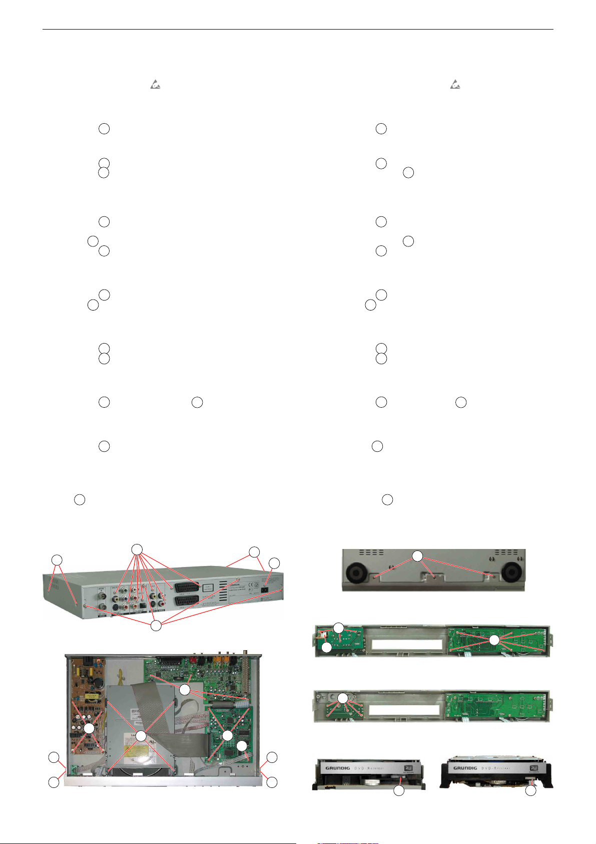
1. Entfernen der Gehäuseteile
– Vor dem Öffenen des Gehäuses das Gerät vom Netz trennen.
– ESD-Vorschriften beachten
– Sicherheitshinweise beachten (siehe Sicherheits-Service-Manual,
Materialnummer 720108000001).
1.1 Gehäuseoberteil
– 8 Schrauben
A
(Fig. 1) herausdrehen.
– Gehäuseoberteil hinten anheben und abnehmen.
1.2 Frontblende
– 5 Schrauben B (Fig. 2/3) herausdrehen.
– 2 Rasthaken C (Fig. 2) lösen und Frontblende abnehmen.
– Gegebenenfalls Steckverbindungen lösen.
2. Ausbauhinweise
2.1 Bedieneinheit, Keyboard, DV-Platte, AV-IN-Platte
– 9 Schrauben D (Fig. 4) herausdrehen.
– Bedieneinheit und Keyboard herausnehmen.
– DV-Platte E (Fig. 4) herausnehmen.
– 5 Schrauben F (Fig. 5) herausdrehen.
– AV-IN-Platte herausnehmen.
– Gegebenenfalls Steckverbindungen lösen.
2.2 Netzteil
– 4 Schrauben G (Fig. 2) herausdrehen.
– Schraube H (Fig. 1) herausdrehen.
– Netzteil herausnehmen.
– Gegebenenfalls Steckverbindungen lösen.
2.3 Buchsenplatte
– 8 Schrauben I (Fig. 1) herausdrehen.
– 4 Schrauben K (Fig. 2) herausdrehen.
– Buchsenplatte herausnehmen.
– Gegebenenfalls Steckverbindungen lösen.
2.4 Hauptplatte
– 3 Schrauben L (Fig. 2) und Schraube M herausdrehen.
– Hauptplatte herausnehmen.
– Gegebenenfalls Steckverbindungen lösen.
2.5 Laufwerk
– 4 Schrauben N (Fig. 2) herausdrehen.
– Laufwerk hinten anheben, nach hinten schieben und herausneh-
men.
– Gegebenenfalls Steckverbindungen lösen.
3 Schublade öffenen bei defektem Laufwerk.
– Hebel O (Fig. 6) nach innen schieben und Schublade herauszie-
hen.
– CD/DVD entnehmen.
.
Service Hints
1. Removing the Cabinet Parts
– Disconnect the set from the mains before opening it.
– Observe the ESD safety regulations
– Observe the savety instructions (see Safety Service Manual, part
number 720108000001).
1.1 Top cover
– Undo 8 screws
A
(Fig. 1)
– Bend the top cover from the rear side and detach from the unit.
1.2 Front Panel
– Undo 5 screws B (Fig. 2/3).
– Release 2 locking lugs C (Fig. 2) and remove the front panel.
– Unplug the connectors if necessary.
2. Disassembly Instructions
2.1 Keyboard Control Unit, Keyboard, DV Board, AV-IN Board
– Undo 9 screws D (Fig. 4).
– Remove the Keyboards Control Unit and the Keyboard.
– Remove the DV Board E (Fig.4).
– Undo 5 screws F (Fig. 5).
– Remove the AV-IN Board.
– Unplug the connectors if necessary.
2.2 Power Supply
– Undo 4 screws G (Fig. 2).
– Undo screw H (Fig. 1).
– Remove the Power Supply Board.
– Unplug the connections if necessary.
2.3 Socket Board
– Undo 8 screws I (Fig. 1).
– Undo 4 screws K (Fig. 2).
– Remove the Socket Board.
– Unplug the connectors if necessary.
2.4 Main Board
– Undo 3 screws L (Fig. 2) and screw M.
– Remove the Main Board.
– Unplug the connectors if necessary.
2.5 Drive Mechanism
– Undo 4 screw N (Fig. 2)
– Lift the Drive Mechanism at its back part, slide it to the rear side and
remove it.
– Unplug the connectors if necessary.
3. Opening the Tray of a Defective Unit
– Slide in the lever O (Fig. 6) and pull out the tray completely.
– Remove the CD/DVD.
.
Fig. 1
C
B
Fig. 2
I
A
A
K
G
N
A
H
L
M
C
B
Fig. 3
D
E
Fig. 4
F
Fig. 5
Fig. 6
1 - 4
B
D
O
O
Page 5

Bedienhinweise
1 - 5
Dieses Kapitel enthält Auszüge aus der Bedienungsanleitung.
Weitergehende Informationen entnehmen Sie bitte der gerätespezifischen Bedienungsanleitung, deren Materialnummer Sie in der ent
GRUNDIG Service GDR 5400
sprechenden Ersatzteilliste finden.
Page 6
1 - 6
GRUNDIG Service GDR 5400
Page 7
1 - 7
GRUNDIG Service GDR 5400
Page 8
1 - 8
GRUNDIG Service GDR 5400
Page 9
1 - 9
GRUNDIG Service GDR 5400
Page 10
GRUNDIG Service GDR 5400
1 - 10
Page 11
GRUNDIG Service GDR 5400
1 - 11
Page 12
GRUNDIG Service GDR 5400
1 - 12
Page 13
GRUNDIG Service GDR 5400
1 - 13
Page 14
GRUNDIG Service GDR 5400
1 - 14
Page 15
GRUNDIG Service GDR 5400
1 - 15
Page 16
GRUNDIG Service GDR 5400
1 - 16
Page 17
GRUNDIG Service GDR 5400
1 - 17
Page 18
GRUNDIG Service GDR 5400
1 - 18
Page 19
GRUNDIG Service GDR 5400
1 - 19
Page 20
GRUNDIG Service GDR 5400
1 - 20
Page 21
GRUNDIG Service GDR 5400
1 - 21
Page 22
GRUNDIG Service GDR 5400
1 - 22
Page 23
GRUNDIG Service GDR 5400
1 - 23
Page 24
GRUNDIG Service GDR 5400
1 - 24
Page 25
GRUNDIG Service GDR 5400
1 - 25
Page 26
GRUNDIG Service GDR 5400
1 - 26
Page 27
GRUNDIG Service GDR 5400
1 - 27
Page 28

GRUNDIG Service GDR 5400
1 - 28
Page 29

GRUNDIG Service GDR 5400
1 - 29
Page 30

GRUNDIG Service GDR 5400
1 - 30
Page 31

GRUNDIG Service GDR 5400
1 - 31
Page 32

GRUNDIG Service GDR 5400
1 - 32
Page 33

Operating Hints
1 - 33
This chapter contains excerpts from the operating instructions.
For further particulars please refer to the appropriate user instructions the part number of which is indicated in the relevant
GRUNDIG Service GDR 5400
spare parts list.
Page 34

GRUNDIG Service GDR 5400
1 - 34
Page 35

GRUNDIG Service GDR 5400
1 - 35
Page 36

GRUNDIG Service GDR 5400
1 - 36
Page 37

GRUNDIG Service GDR 5400
1 - 37
Page 38

GRUNDIG Service GDR 5400
1 - 38
Page 39

GRUNDIG Service GDR 5400
1 - 39
Page 40

GRUNDIG Service GDR 5400
1 - 40
Page 41

GRUNDIG Service GDR 5400
1 - 41
Page 42

GRUNDIG Service GDR 5400
1 - 42
Page 43

GRUNDIG Service GDR 5400
1 - 43
Page 44

GRUNDIG Service GDR 5400
1 - 44
Page 45

GRUNDIG Service GDR 5400
1 - 45
Page 46

GRUNDIG Service GDR 5400
1 - 46
Page 47

GRUNDIG Service GDR 5400
1 - 47
Page 48

GRUNDIG Service GDR 5400
1 - 48
Page 49

GRUNDIG Service GDR 5400
1 - 49
Page 50

GRUNDIG Service GDR 5400
1 - 50
Page 51

GRUNDIG Service GDR 5400
1 - 51
Page 52

GRUNDIG Service GDR 5400
1 - 52
Page 53

GRUNDIG Service GDR 5400
1 - 53
Page 54

GRUNDIG Service GDR 5400
1 - 54
Page 55

GRUNDIG Service GDR 5400
1 - 55
Page 56

GRUNDIG Service GDR 5400
1 - 56
Page 57

GRUNDIG Service GDR 5400
1 - 57
Page 58

GRUNDIG Service GDR 5400
1 - 58
Page 59

GRUNDIG Service GDR 5400
1 - 59
Page 60

GRUNDIG Service GDR 5400
1 - 60
Page 61

GRUNDIG Service GDR 5400
Platinenabbildungen und Schaltpläne / Layout of the PCBs and Circuit Diagrams
Verdrahtungsplan / Wiring Diagram
Socket Board
JP601 JP602
J1001
DV Board
Power Supply
AV-IN Board
Keyboard
J905
J902
J901
J604
JP1001
DVD Drive
JP703
Keyboard Control Unit
J8 J10
J7
J6
Main Board
J3
J4
J2
JP702JP701
2 - 1
Page 62

Netzteil / Power Supply
Ansicht von der Bestückungsseite / View of Component Side
2 - 2
GRUNDIG Service GDR 5400
Page 63

TO FRONT PANEL
TO CODEC BOARD
TO LOADER
+12V
FIP1
25NV
-12V
3V3
12V
+5V
-12V
-12V
2.5V
3.3V
+5V
+5V
2V5
5VSTB
5VSTBY
PWR_CTL
PWR_CTL
5VSTBY
FIP1
5VSTBY
25NV
FIP2
FIP2
+5V
C974
104
U901
L6565
1
2
3
4
5
6
7
8
INV
COM
MUL
CS ZCD
GND
GD
VCC
R931
1K
R991
1K
VD965
6V8
C941
104
+
C972
1000uF/10V
R941
10K
+
C961
2200uF/10V
U953
78R12
1
2
3
4
IN OUT
GND
CON
F901
T2AL 250V
D955
FR104
U931
TL431
R996
10K
+
C992
470uF/16V
C904
0.1uF/275V
L901
LCL16015
R962
100
C905
0.1uF/275V
R905
270K
U902
PC817B
1
2
3
4
V901
STP3NC60FP
R935
10K
D907
1N4148
R906
270K
D974
FR107
R911
100
R901
1M/1W
V957
S8550
R902
47K/1W
L951
2.2uH
L953
5.6uH
D906
1N4148
J906
PH10/2MM
10
9
8
7
6
5
4
3
2
1
C907
472/1KV
VD955
27V
C931
104
R910
33K
C985
104
+
C965
22uF/50V
R963 470
D953
HER306
R967
100
F951
4A/125V
R903
1M5
R966
100
R904
10K
D901
1N4007
R934
2K4
L952
2.2uH
+
C963
470uF/16V
D902
1N4007
+
C971
1000uF/10V
D903
1N4007
+
C993
220UF/25V
D904
1N4007
R916
10K
R965
200
+
C994
220UF/25V
R912
10K
+
C982
220uF/10V
VD957
3V9
R917
2K4
L956
5.6uH
J902
TJC3-4A
1
2
3
4
+
C906
68uF/400V
J901
PH13/2MM
13
12
11
10
9
8
7
6
5
4
3
2
1
U952
1N4007
C903
102/400V
R908
10/2W
+
C962
1000uF/16V
C901
1nF/400V
V951
STP22NE03L
C902
1nF/400V
U951
TL431
U972
78R05
1
2
3
4
IN OUT
GND
CON
R981
2K7
D952A
SR560
+
C910
47uF/16V
R918
47
D952B
SR560
R992
220
R971
DNS-4K7
T901
BCK-70-01B
1
2
3
4
5
6
7
8
9
10
11
12
13
14
15
D905
FR107
+
C973
470uF/16V
L955
10uH
V955
2SA1015
+
C981
10uF/50V
C911
152
D956
RL252
R915
470
+
C975
10uF/50V
D951A
SR540
D957
FR104
R914
22K
C908
104
D951B
SR540
R952
6R8
VD901
18V
R951
6R8
C951
103/500V
+
C967
100uF/16V
R961
1K
D958
RL252
C952
103/500V
J900
AC INPUT
1
2
R932
3K3
1
2
Netzteil / Power Supply
2 - 3
GRUNDIG Service GDR 5400
Page 64

GRUNDIG Service GDR 5400
Hauptplatte / Main Board
Ansicht von der Bestückungsseite / View of Component Side
2 - 4
Page 65

GRUNDIG Service GDR 5400
Hauptplatte / Main Board
Ansicht von der Lötseite / View of Solder Side
2 - 5
Page 66

TERMINATION
AT E5.1
TERMINATION
AT DDR
DDR TERMINATION VOLTAGE REGULATOR
MAIN POWER CONN
FROM POWER BOARD
For DDR VDD-2.5V
For Video Deco de
SDRAM_CS0
E5_SDRAM_DQ3
E5_SDRAM_DQ1
E5_SDRAM_DQ2
E5_SDRAM_DQ0
E5_SDRAM_DQ4
E5_SDRAM_DQ5
E5_SDRAM_DQ6
E5_SDRAM_DQ7
E5_SDRAM_DQ8
E5_SDRAM_DQ9
E5_SDRAM_DQ10
E5_SDRAM_DQ11
E5_SDRAM_DQ12
E5_SDRAM_DQ13
E5_SDRAM_DQ14
E5_SDRAM_DQ15
E5_SDRAM_DQ16
E5_SDRAM_DQ17
E5_SDRAM_DQ18
E5_SDRAM_DQ19
E5_SDRAM_DQ20
E5_SDRAM_DQ21
E5_SDRAM_DQ22
E5_SDRAM_DQ23
E5_SDRAM_DQ24
E5_SDRAM_DQ25
E5_SDRAM_DQ26
E5_SDRAM_DQ27
E5_SDRAM_DQ31
E5_SDRAM_DQ29
E5_SDRAM_DQ30
E5_SDRAM_DQ28
SDRAM_CLK1
SDRAM_CLK#1
SDRAM_CLK#0
SDRAM_CLK0
SDRAM_RAS#
SDRAM_WE#
SDRAM_CLKE
SDRAM_CAS#
SDRAM_A5
SDRAM_A3
SDRAM_A15
SDRAM_A4
SDRAM_A9
SDRAM_A14
SDRAM_A11
SDRAM_A0
SDRAM_A2
SDRAM_A12
SDRAM_A8
SDRAM_A6
SDRAM_A7
SDRAM_A1
SDRAM_DQM3
SDRAM_DQM2
SDRAM_DQS2
SDRAM_DQS3
SDRAM_DQS0
SDRAM_DQS1
SDRAM_A10
SDRAM_DQM0
SDRAM_DQM1
SDRAM_DQ7
SDRAM_DQ3
SDRAM_DQ24
SDRAM_DQ21
SDRAM_DQ17
SDRAM_DQ19
SDRAM_DQ15
SDRAM_DQ28
SDRAM_DQ7
SDRAM_DQ29
SDRAM_DQ30
SDRAM_DQ8
SDRAM_DQ14
SDRAM_DQ12
SDRAM_DQ13
SDRAM_DQ21
SDRAM_DQ3
SDRAM_DQ23
SDRAM_DQ17
SDRAM_DQ9
SDRAM_DQ22
SDRAM_DQ27
SDRAM_DQ23
SDRAM_DQ5
SDRAM_DQ6
SDRAM_DQ27
SDRAM_DQ28
SDRAM_DQ30
SDRAM_DQ6
SDRAM_DQ29
SDRAM_DQ10
SDRAM_DQ19
SDRAM_DQ18
SDRAM_DQ16
SDRAM_DQ26
SDRAM_DQ5
SDRAM_DQ20
SDRAM_DQ25
SDRAM_DQ31
SDRAM_DQ0
SDRAM_DQ0
SDRAM_DQ22
SDRAM_DQ16
SDRAM_DQ9
SDRAM_DQ1
SDRAM_DQ25
SDRAM_DQ14
SDRAM_DQ13
SDRAM_DQ10
SDRAM_DQ18
SDRAM_DQ15
SDRAM_DQ26
SDRAM_DQ12
SDRAM_DQ2
SDRAM_DQ4
SDRAM_DQ1
SDRAM_DQ20
SDRAM_DQ31
SDRAM_DQ11
SDRAM_DQ24
SDRAM_DQ2
SDRAM_DQ8
SDRAM_DQ4
SDRAM_DQ11
GND_SSTL2
GND_SSTL2
GND_SSTL2
GND_SSTL2
GND_SSTL2
VTT
VTT
V33CONN
V5CONN
+12V
-12V
DLED
+5VSTB
V2.5CONN
VREF
VREF
CHASSIS_GND
SDRAM_DQ[31..0]
E5_SDRAM_DQ[31..0]
E5_SDRAM_CLK#1
E5_SDRAM_CLK1
E5_SDRAM_CLK0
E5_SDRAM_CLK#0
E5_SDRAM_CAS#
E5_SDRAM_CS0
E5_SDRAM_DQM0
E5_SDRAM_DQM2
E5_SDRAM_DQM1
E5_SDRAM_DQM3
E5_SDRAM_DQS0
E5_SDRAM_DQS2
E5_SDRAM_DQS1
E5_SDRAM_DQS3
VREF
VREF
E5_SDRAM_RAS#
E5_SDRAM_CLKE
E5_SDRAM_WE#
E5_SDRAM_A3
E5_SDRAM_A15
E5_SDRAM_A1
E5_SDRAM_A6
E5_SDRAM_A12
E5_SDRAM_A14
E5_SDRAM_A9
E5_SDRAM_A4
E5_SDRAM_A2
E5_SDRAM_A5
E5_SDRAM_A0
E5_SDRAM_A11
E5_SDRAM_A7
E5_SDRAM_A8
E5_SDRAM_A10
SDRAM_DQM2
SDRAM_DQM0
SDRAM_CLK0
SDRAM_DQS2
SDRAM_A0
SDRAM_A3
SDRAM_A5
SDRAM_A11
SDRAM_A12
SDRAM_A4
SDRAM_RAS#
SDRAM_WE#
SDRAM_DQS3
SDRAM_DQM1
SDRAM_CLK1
SDRAM_CS0
SDRAM_DQ[31..0]
SDRAM_A1
SDRAM_A7
SDRAM_A8
SDRAM_A10
SDRAM_A15
SDRAM_CAS#
SDRAM_DQS0
SDRAM_DQS1
SDRAM_DQM3
SDRAM_CLK#1
SDRAM_CLK#0
SDRAM_A2
SDRAM_A6
SDRAM_A9
SDRAM_A14
SDRAM_CLKE
VREF
E5_GPIOx33
SSTL2_VDD
SSTL2_VDD
VTT
SSTL2_VDD
SSTL2_VDD
VTT
VTT
SSTL2_VDD
VTT
V18
V25_CON
GND
V25_CON
V5CONN
GND
+5VSTB
-12V
VCC
V33
GND
GND
+12V
GND
GND
GND
V33
V25
CHASSIS_GND
GND
GND
V18
V18_VI
V33
V33_PHY_A
GND
GND
E5_V5BIAS
U9
PQ018EZ02/PQ070XZ02
1
5
3
2
4
6
VIN
GND
VOUT1
VC
ADJ
VOUT2
C327
1000PF
RP44 22/RP
1
8
2
7
3
6
4
5
RP19 51/RP
1
8
2
7
3
6
4
5
+
CA5
220UF/10V
RP26 51/RP
1
8
2
7
3
6
4
5
R20 51
C130
0.1UF
RP43 22/RP
1
8
2
7
3
6
4
5
L7 FBMJ2125HS420-T
RP28 51/RP
1
8
2
7
3
6
4
5
+
CA15
220UF/10V
C120
0.1UF
RP21 51/RP
1
8
2
7
3
6
4
5
FB4
FBMJ3216HS800-T
FB100
PZ2012U420-4R0T
MT1
MountHole
1
2
3
4
5
6
7
8
9
H
2
3
4
5
6
7
8
9
RP8 51/RP
1
8
2
7
3
6
4
5
R27 22
MT2
MountHole
1
2
3
4
5
6
7
8
9
H
2
3
4
5
6
7
8
9
+
CA12
220UF/10V
RP22 51/RP
1
8
2
7
3
6
4
5
C129
0.1UF
RP23 51/RP
1
8
2
7
3
6
4
5
+
CA8
220UF/10V
R162 51
RP35 22/RP
1
8
2
7
3
6
4
5
RP24 51/RP
1
8
2
7
3
6
4
5
+
CA22
47UF/10V
R362
DNS_1K
R164 51
C403
0.1UF
C324
1000PF
+
CA29
220UF/10V
RP10 51/RP
1
8
2
7
3
6
4
5
C319
1000PF
RP32 51/RP
1
8
2
7
3
6
4
5
C39
0.1UF
R19 51
C282
0.01UF
C37
0.1UF
C287
0.01UF
FB93
FBMJ2125HS420-T
+
CA28
220UF/10V
C115
0.1UF
C281
0.01UF
+
CA7
220UF/10V
C131
0.1UF
FB94
FBMJ2125HS420-T
C290
0.01UF
C286
0.01UF
FB1
FBMJ3216HS800-T
+
CA36
100UF/10V
FB95
FBMJ2125HS420-T
R13 22
C292
0.01UF
C283
0.1UF
+
CA31
330UF/10V
C402
0.1UF
FB96
BK1608HM601
-T
C416
0.1UF
C291
0.01UF
C288
0.1UF
FB97
BK1608HM601
-T
R14 22
U26
LP2995
1
2
3
4
5
6
7
8
NC
GND
VSENSE
VREF VDDQ
AVIN
PVIN
VTT
FB98
BK1608HM601
-T
R251
DNS_1K
R31 51
FB99
BK1608HM601
-T
R16 22
C417
0.1UF
R454
DNS_1K
+
CA19
10UF/10V
MT3
MountHole
1
2
3
4
5
6
7
8
9
H
2
3
4
5
6
7
8
9
R444 51
R361
DNS_1K
C40
0.1UF
R18 22
RP48 22/RP
1
8
2
7
3
6
4
5
C135
0.1UF
C133
0.1UF
C315
0.1UF
C280
0.1UF
FB3
FBMJ3216HS800-T
R17 51
R443 51
MT4
MountHole
1
2
3
4
5
6
7
8
9
H
2
3
4
5
6
7
8
9
R3
DNS_0
C418
0.1UF
R21 51
C326
1000PF
D1
LED_GREEN
1
2
C294
0.01UF
C321
1000PF
+
CA10
47UF/10V
R22 51
C127
0.1UF
R8 51
C295
0.01UF
RP47 22/RP
1
8
2
7
3
6
4
5
C112
0.1UF
R58
300
C123
0.1UF
C300
0.01UF
R252
DNS_2.2K
R24 51
C136
0.1UF
R10 51
C301
0.01UF
C124
0.1UF
+
C298
10UF/6V/A
C296
0.1UF
R23 51
RP12 51/RP
1
8
2
7
3
6
4
5
R6 51
C297
0.1UF
C285
0.1UF
+
C299
10UF/6V/A
C302
0.1UF
C328
1000PF
C279
0.1UF
U10
PQ025EZ01
1
5
3
2
4
6
VIN
GND
VOUT1
VC
ADJ
VOUT2
RP14 51/RP
1
8
2
7
3
6
4
5
R5 51
C303
0.1UF
C323
1000PF
J7
13 HEADER 2.0MM CABLE WIRE
1
2
3
4
5
6
7
8
9
10
11
12
13
RP11 51/RP
1
8
2
7
3
6
4
5
C116
0.1UF
C284
0.1UF
FB2
FBMJ3216HS800-T
RP15 51/RP
1
8
2
7
3
6
4
5
RP18 51/RP
1
8
2
7
3
6
4
5
RP20 51/RP
1
8
2
7
3
6
4
5
C325
1000PF
RP7 51/RP
1
8
2
7
3
6
4
5
C320
1000PF
+
CA13
330UF/10V
RP9 51/RP
1
8
2
7
3
6
4
5
FB92
PZ2012U420-4R0T
C119
0.1UF
R15 51
C128
0.1UF
RP13 51/RP
1
8
2
7
3
6
4
5
C329
0.1UF
RP17 51/RP
1
8
2
7
3
6
4
5
C139
0.1UF
R11 51
RP45 22/RP
1
8
2
7
3
6
4
5
C42
0.1UF
R442 51
C43
0.1UF
R168 51
C111
0.1UF
C322
1000PF
The VTT side of the terminaton resistors should be placed
on a wide VTT island on the surface layer. The island is
located at each end of the bus, so it does not i
nterfere
with the signal rout
ing.
VREF needs to be decoupled
to both SSTL2_VDD and SSTL2_GND with balancedd
ecoupling capacitors.
VREF should be routed o
ver a
reference plane and isolated, and po
ssibly
shielded with both SSTL2_VDD and SSTL2_GND
2 - 6
Hauptplatte – Netzteil / Main Board
– Power Supply
GRUNDIG Service GDR 5400
Page 67

1MB
R109
R109,R106
R104,R106,R107
2MB
R104,R106,R107,R109
R104,R107
FLASH MEMORY(2 or 4 or 8 Mb)
R104,R106,R107
Not StuffSize
8MB
R109
4MB
Stuff
SDRAM_DQ1
SDRAM_DQ3
SDRAM_DQ2
SDRAM_DQ4
SDRAM_DQ5
SDRAM_DQ7
SDRAM_DQ6
SDRAM_DQ0
SDRAM_DQ14
SDRAM_DQ15
SDRAM_DQ13
SDRAM_DQ8
SDRAM_DQ10
SDRAM_DQ12
SDRAM_DQ9
SDRAM_DQ11
SDRAM_A0
SDRAM_A10
SDRAM_A1
SDRAM_A11
SDRAM_A8
SDRAM_A3
SDRAM_A9
SDRAM_A2
SDRAM_A11
SDRAM_A1
SDRAM_A5
SDRAM_A2
SDRAM_A8
SDRAM_A3
SDRAM_A6
SDRAM_A7
SDRAM_A0
SDRAM_A9
SDRAM_A4
SDRAM_A10
SDRAM_A14
SDRAM_A12
SDRAM_A15
SDRAM_DQ28
SDRAM_DQ30
SDRAM_DQ31
SDRAM_DQ22
SDRAM_DQ21
SDRAM_DQ19
SDRAM_DQ26
SDRAM_DQ25
SDRAM_DQ20
SDRAM_DQ23
SDRAM_DQ24
SDRAM_DQ17
SDRAM_DQ18
SDRAM_DQ27
SDRAM_DQ29
SDRAM_DQ16
SDRAM_A6
SDRAM_A5
SDRAM_A4
SDRAM_A12
SDRAM_A14
SDRAM_A15
SDRAM_A7
GND_SSTL2
HD12
BA12
BA1
HD0
ACC
BA3
BA4
HD13
BA17
BA16
HD4
BA9
BA4
BA11
HD10
BA9
HD5
A19/A19/A21
RY/BY/A19
HD14
BA22
BA3
BA22
BA18
BA14
BA11
HD6
BA17
HD11
HD7
BA13
HD0
HD2
BA6
BA18
HD1
BA12
HD15
HD10
BA20
BA21
A19/A19/A21
BA10
BA16
BA19
BA[22..1]
BA14
BA1
WP#/ACC
BA8
BA15
BA13
HD9
/SYS_RST
HD9
HD6
HD1
BA5
HD8 HD12
HD3
BA6
HD7
BA8
HD3
BA2
HD8
RY/BY/A19
BA5
BA7
BA17
BA7
NC/A20/A20
BA2
BA20
BA10
HD15
BA15
HD11
HD4
BA1
BA19
HD14 HD2
HD13
HD5
NC/A20/A20
WP#/ACC
BA21
SDRAM_DQ[31..0]
SDRAM_DQS2
SDRAM_DQS3
SDRAM_DQS1
SDRAM_DQS0
SDRAM_CS0
SDRAM_CLKE
SDRAM_RAS#
SDRAM_CAS#
SDRAM_WE#
SDRAM_DQM1
SDRAM_DQM0
SDRAM_DQM2
SDRAM_DQM3
VREF
SDRAM_CLK0
SDRAM_CLK#0
SDRAM_CS0
SDRAM_CLK1
SDRAM_CLK#1
SDRAM_A0
SDRAM_A7
SDRAM_A14
SDRAM_A10
SDRAM_A12
SDRAM_A3
SDRAM_A1
SDRAM_A8
SDRAM_A9
SDRAM_A4
SDRAM_A15
SDRAM_A11
SDRAM_A6
SDRAM_A2
SDRAM_A5
SDRAM_A2
SDRAM_A3
SDRAM_A14
SDRAM_A7
SDRAM_A6
SDRAM_A8
SDRAM_A12
SDRAM_A4
SDRAM_A9
SDRAM_A10
SDRAM_A0
SDRAM_A1
SDRAM_A5
SDRAM_A11
SDRAM_A15
E5_MA22
/E5_OE
E5_MA1
/SYS_RST
/E5_CS0
E5_MA2
E5_MA3
E5_ALE
HD[15..0]
HD[15..0]
E5_MA5
/E5_WEL
E5_MA4
SSTL2_VDD
SSTL2_VDD
SSTL2_VDD
GND
GND
GND
GND
GND
GND
GND
SSTL2_VDD
SSTL2_VDD
V33
V33
V33
C96
0.1UF
R97
0
C95
0.1UF
U25
8MX16 DDR
29
30
31
32
35
36
37
38
39
40
28
41
26
27
24
44
23
22
21
20
47
65
63
62
60
59
57
56
13
11
54
10
8
7
5
4
2
16
51
45
46
1
18
33
3
9
15
55
61
49
34
48
66
6
12
52
58
64
14
17
19
25
42
43
50
53
A0
A1
A2
A3
A4
A5
A6
A7
A8
A9
A10/AP
A11
BA0
BA1
CS#
CKE
RAS#
CAS#
WE#
LDM
UDM
D15
D14
D13
D12
D11
D10
D9
D7
D6
D8
D5
D4
D3
D2
D1
D0
LDQS
UDQS
CLK
CLK#
VCC
VCC
VCC
VCCQ
VCCQ
VCCQ
VCCQ
VCCQ
VREF
GND
GND
GND
GNDQ
GNDQ
GNDQ
GNDQ
GNDQ
NC
NC
NC
NC
A12
NC
NC
NC
U14
MX29LV160
1
2
3
4
5
6
7
8
9
10
11
12
13
14
15
16
17
18
19
20
21
22
23
24
48
47
46
45
44
43
42
41
40
39
38
37
36
35
34
33
32
31
30
29
28
27
26
25
A15
A14
A13
A12
A11
A10
A9
A8
A19/A19/A21
NC/A20/A20
WE
RST
ACC
WP/ACC
RY/BY/A19
A18
A17
A7
A6
A5
A4
A3
A2
A1
A16
BYTE/VIO
VSS
D15
D7
D14
D6
D13
D5
D12
D4
VCC
D11
D3
D10
D2
D9
D1
D8
D0
OE
VSS
CE
A0
U13
74LVC16373
47
46
44
43
41
40
38
37
1
48
36
35
33
32
30
29
27
26
24
25
2
3
5
6
8
9
11
12
13
14
16
17
19
20
22
23
4
10
15
21
28
34
39
45
7
18
31
42
1A1
1A2
1A3
1A4
1A5
1A6
1A7
1A8
1OE
1LE
2A1
2A2
2A3
2A4
2A5
2A6
2A7
2A8
2OE
2LE
1B1
1B2
1B3
1B4
1B5
1B6
1B7
1B8
2B1
2B2
2B3
2B4
2B5
2B6
2B7
2B8
GND
GND
GND
GND
GND
GND
GND
GND
VCC
VCC
VCC
VCC
C71
0.1UF
R107 DNS-0
U22
8MX16 DDR
29
30
31
32
35
36
37
38
39
40
28
41
26
27
24
44
23
22
21
20
47
65
63
62
60
59
57
56
13
11
54
10
8
7
5
4
2
16
51
45
46
1
18
33
3
9
15
55
61
49
34
48
66
6
12
52
58
64
14
17
19
25
42
43
50
53
A0
A1
A2
A3
A4
A5
A6
A7
A8
A9
A10/AP
A11
BA0
BA1
CS#
CKE
RAS#
CAS#
WE#
LDM
UDM
D15
D14
D13
D12
D11
D10
D9
D7
D6
D8
D5
D4
D3
D2
D1
D0
LDQS
UDQS
CLK
CLK#
VCC
VCC
VCC
VCCQ
VCCQ
VCCQ
VCCQ
VCCQ
VREF
GND
GND
GND
GNDQ
GNDQ
GNDQ
GNDQ
GNDQ
NC
NC
NC
NC
A12
NC
NC
NC
C334
0.1UF
R102 0
C333
0.1UF
C332
0.1UF
+
C34 10UF/6V/A
C341
0.1UF
C306
1000PF
C340
0.1UF
+
C38 10UF/6V/A
C307
1000PF
C69
0.1UF
C339
0.1UF
C310
1000PF
C109
1000PF
C311
1000PF
C335
1000PF
C336
1000PF
C108
1000PF
C337
1000PF
+
C338
10UF/6V/A
C107
0.1UF
R106 DNS-0
C342
1000PF
C106
0.1UF
C343
1000PF
C344
1000PF
C105
0.1UF
+
C345
10UF/6V/A
C101
1000PF
C70
0.1UF
C104
0.1UF
C100
1000PF
C103
0.1UF
C99
0.1UF
R109 0
R145
10K
C98
0.1UF
R104 DNS-0
C97
0.1UF
Hauptplatte – Speicher / Main Board
– Memory
GRUNDIG Service GDR 5400
2 - 7
Page 68

RESET CIRCUITRY
E-Link IV
Connector
FRONT PANEL CONNECTOR
FRONT PANEL INTERFACE
D_HOST
D_FM
FP_SCLK
RDY_FM
ATN_FM
/FP_RST
A/V I/O Connector
IRRX
Reserve
To AVIO Board
For Stereo audio output only, don't stuff FB24,FB25,FB26; JP2 use FMN24/1.0mm.
For 5.1 channel audio output, stuff FB24,FB25,FB26; JP2 use FMN28/1.0mm.
/ETHER_IRQ
User can put a 10 pins 2MM
header J8 without putting
the 40 pins hea der JP7 for
UART
(MUTE)
(Input Only)
BTSC and AUDIO RESET
(Ain_Sel1)
(Ain_Sel0)
MAX809
TO AVIO BOARD
IR EMITTER
To AVIO Board
256Mb DDR SDRAM
HOST Read
HD[7]
11
10
Debuge Mode (Jumper 2-3)
11
HD[3:2 ]
Samsung - K4H281638D-TCB3
64Mb DDR SDRAM
00
Nanya
00
Micron - MT46V8M16-55
01
128Mb DDR SDRAM
10
ESMT - M13S128168A-6T
HD[1:0 ]
Reserve
Normal Mode (Jumper 1-2)
KEYWAY (NO PIN)
01
0
DEDICATED ATAPI INTERFACE
1
/RST_HOST
FP_GND
FP_P4
FP_P1
FP_P8
FP_P5
FP_P3
FP_P2
FP_IR
/RST_SW
+3.3V
MUT
E
/RST_HOST
/RST_SW /SYS_RST
I2C_ENA /SYS_RST
SDA_5V
SCL_5V
SCL
SDA_5V
SCL_5V
SDA
-12V
AUDIO_L
AUDIO_R
+5V
+5VSTB
SCL
SDA
HD1
ATA_A 1
INT_ATA
CS3FX
HD_AT10
HD_AT4
CS3FX
HD_AT14
ATA_A 0
DIOR
HD_AT1
HD_AT11
HD_AT3
INT_ATA
HD_AT13
DIOW
HD_AT9
HD_AT1
HD_AT6
CS1FX
HD_AT0
HD_AT3
HD_AT8
HD_AT14
RSTAT A
HD2
HD_AT4
HD_AT5
HD_AT12
HD3
HD5
DMARQ
HD_AT2
HD_AT8
IORDY
IORDY
DMACK
HD_AT9
ATA_A 0
HD_AT7
DIOW
HD0
CS1FX
HD_AT6
HD_AT7
ATA_A 2
HD_AT0
HD_AT10
HD_AT11
HD_AT15
ATA_A 1
HD_AT12
CAB_SEL
HD_AT2
HD_AT13
HD4
HD6
ATA_A 2
DIOR
HD7
DMARQ
HD_AT5
RSTAT A
HD_AT15
DMACK
E5_GPIO0
E5_GPIOx42
E5_GPIOx41
E5_GPIOx24
E5_GPIOx25
AO_D0
AO_D3
AO_FSYNC
E5_SIO_IRRX
TV_CVBS_IN
Y/G_IN
Pb/B_IN
Pr/R_IN
R_C_IN
AO_D2
AO_D1
E5_GPIO3
/E5_UDS
/E5_CS1
E5_ALE
E5_GPIO2
E5_MA 3
E5_MA 5
/E5_WEL
E5_MA 2
E5_MA 4
/E5_OE
E5_MA 1
/WAIT
E5_UART2_RX
E5_UART 2_T
X
HD15
HD13
HD11
HD9
HD8
HD6
HD4
HD2
HD0
HD14
HD12
HD10
HD7
HD5
HD3
HD1
E5_/DTACK
Pr/R_Out
Pb/B_Out
Y/G_Out
Y_Out
CVBS_Out
C_Out
AO_SCLK
AO_MCLKO
AI_D0
AI_FSYNC
AO_IEC958
AI_SCLK
E5_SPI_MOSI
E5_GPIOx5
E5_SPI_CLK
E5_SPI_MISO
AI_MCLKO
/SYS_RST
E5_GPIO6
VI_GPIO_C4
E5_GPIOx4
E5_GPIO4
E5_GPIO5
/SYS_RST
SCL
SCL_5V
SDA_5V
E5_GPIOx35
SDA
AUDIO_R
AUDIO_L
VI_FSS
VI_GPIO_C9
E5_GPIOx32
VI_GPIO_C6
VI_GPIO_C5
CVBS_IN
R_Y_IN
E5_IRTX1
SCL
SDA
ATAPI_DATA1
ATAPI_DATA4
ATAPI_DIOW_L
ATAPI_DATA8
ATAPI_DATA9
ATAPI_RESET
HD[15..0]
ATAPI_DATA7
AtapiAddr1
AtapiAddr0
ATAPI_IORDY
ATAPI_DATA10
ATAPI_DATA2
AtapiAddr2
ATAPI_DATA12
ATAPI_DATA6
ATAPI_DATA15
ATAPI_DATA5
ATAPI_DIOR_L
ATAPI_DATA13
ATAPI_DATA14
ATAPI_DATA0
ATAPI_DMAACK_L
ATAPI_DATA11
AtapiAddr4
ATAPI_DMARQ
AtapiAddr3
ATAPI_DATA3
ATAPI_INTRQ
E5_SPI_CS2
V33
GND
GND
GND
V33
GND
V33
GND
GND
GND
GND
V33
GND
V33
V33
VCC
VCC
GND
V33
GND
+12V
-12V
V5CONN
+5VSTB
V33
V33
V33
VCC
VCC
V33
GND
VCC
V33
FB68 BK1608HM601 -T
R532 0
FB18BK1608HM601-T
R111 82
FB129 BK1608HM601 -T
FB30 BK1608HM601-T
FB70 BK1608HM601 -T
FB82 BK1608HM601 -T
R124 10K
FB130 BK1608HM601 -T
C251
0.1UF
FB72 BK1608HM601 -T
R533 0
R113 82
FB74 BK1608HM601 -T
JP1
DNS HEADER 3X1
1
2
3
FB76 BK1608HM601 -T
R112 82
FB83 BK1608HM601 -T
+
CA413
47UF/10V
FB78 BK1608HM601 -T
FB80 BK1608HM601 -T
FB117BK1608HM601-T
R116
10K
FB45BK1608HM601-T
FB14
BK1608HM601-T
FB37 BK1608HM601-T
C346
0.1UF
FB84 BK1608HM601 -T
U21
TPS3809I50
1
2
3
GND
RST
VDD
R115 0
J8
HEADER 22X2(2.0MM) CABLE WIRE
1
3
5
7
9
11
13
15
17
19
21
23
25
27
29
31
33
35
37
39
41
43
2
4
6
8
10
12
14
16
18
20
22
24
26
28
30
32
34
36
38
40
42
44
FB42 BK1608HM601-T
FB22 BK1608HM601-T
FB19 BK1608HM601-T
FB116BK1608HM601-T
FB63 BK1608HM601 -T
Q1 DNS-2N2222
2
1
3
C253
0.1UF
FB7
BK1608HM601-T
FB85 BK1608HM601 -T
FB28 BK1608HM601-T
R36DNS-10K
D9 IN4148
1
2
R38DNS-10K
FB8
BK1608HM601-T
R37
10K
R447
10K
FB41 BK1608HM601-T
R448
10K
FB46BK1608HM601-T
J13
DNS-PH2/2MM
2MM PITCH
PH2-TH
1
2
FB86 BK1608HM601 -T
FB32 BK1608HM601-T
FB36 BK1608HM601-T
J4
PH8/2MM
2MM PITCH
PH8-TH
1
2
3
4
5
6
7
8
FB65 BK1608HM601 -T
D7 IN4148
1
2
FB29 BK1608HM601-T
RP5 33/RP
1
8
2
7
3
6
4
5
FB60
DNS-BK1608HM601-T
FB9
BK1608HM601-T
C437 0.1UF
R216
220
FB21 BK1608HM601-T
FB87 BK1608HM601 -T
FB67 BK1608HM601 -T
RP27 33/RP
1
8
2
7
3
6
4
5
FB136BK1608HM601-T
FB10
BK1608HM601-T
R132 10K
FB12 BK1608HM601-T
FB20 DNS-BK1608HM601-T
RP4 33/RP
1
8
2
7
3
6
4
5
R423
DNS-100
FB38 BK1608HM601-T
R134 10K
FB135 DNS-BK1608HM601-T
FB88 BK1608HM601 -T
FB69 BK1608HM601 -T
FB118BK1608HM601-T
FB134 DNS-BK1608HM601-T
R355 1.2K
FB35 BK1608HM601-T
FB11
BK1608HM601-T
R135 10K
R50
DNS-10K
FB15BK1608HM601-T
C350
0.1UF
FB39 FBMJ2125HS420-T
R118 DNS-10K
FB71 BK1608HM601 -T
FB90 BK1608HM601 -T
C1
0.01UF
R100
4.7K
FB13
BK1608HM601-T
R129 10K
U31
AT24C16
1
2
3
4
5
6
7
8
A0
A1
A2
GND SDA
SCL
WP
VCC
R101
4.7K
R127
0
FB73 BK1608HM601 -T
FB121 DNS-BK1608HM601-T
R453
DNS-10K
R120 DNS-10K
R1 0
FB122 DNS-BK1608HM601-T
R126
4.7K
R2 0
R122 DNS-10K
C74
22PF
FB75 BK1608HM601 -T
C351
1000PF
R119 DNS-10K
FB1070
J3
HEADER 20X2
12
34
56
78
910
11 12
13 14
15 16
17 18
19 20
21 22
23 24
25 26
27 28
29 30
31 32
33 34
35 36
37 38
39 40
FB26 DNS-BK1608HM601-T
FB1080
FB25 DNS-BK1608HM601-T
R131 10K
R44
10K
FB1090
R114
4.7K
FB77 BK1608HM601 -T
FB16BK1608HM601-T
FB24 DNS-BK1608HM601-T
FB91 BK1608HM601 -T
FB110BK1608HM601-T
FB27 BK1608HM601-T
J10
28PIN 1.0MM FFC
1
2
3
4
5
6
7
8
9
10
11
12
13
14
15
16
17
18
19
20
21
22
23
24
25
26
27
28
FB111BK1608HM601-T
R133 10K
FB89 BK1608HM601 -T
J11
DNS-TCON-05/2.0mm
1
2
3
4
5
FB112BK1608HM601-T
FB131 FBMJ2125HS420-T
R125
680
FB31 BK1608HM601-T
RP40 33/RP
1
8
2
7
3
6
4
5
+
C349
10UF/6V/A
R130 10K
FB79 BK1608HM601 -T
J5
HEADER 20X2
12
34
56
78
910
11 12
13 14
15 16
17 18
19 20
21 22
23 24
25 26
27 28
29 30
31 32
33 34
35 36
37 38
39 40
R117 DNS-10K
R534 0
U2 DNS-PCA9515
8
7
6
5
1
2
3
4
3.3V
SCL_1
SDA_1
E1
NC
SCL_0
SDA_0
GND
R438
DNS-10K
R128 10K
R439
DNS-10K
RP25 33/RP
1
8
2
7
3
6
4
5
R121 DNS-10K
FB81 BK1608HM601 -T
FB17BK1608HM601-T
RP6 33/RP
1
8
2
7
3
6
4
5
C410
0.1UF
R35DNS-10K
FB66 BK1608HM601 -T
R123 DNS-10K
C414
0.1UF
R33DNS-10K
R34DNS-10K
7
15
8
9
10
9
10
19
9
10
3
3
6
16
141312
11
38
36
40
Hauptplatte – / Main Board – Interface
GRUNDIG Service GDR 5400
2 - 8
Page 69

IDC Slave Addr:
0xB8/B9
(Fast switch input source
between RGB andCVBS/YC)
(/RST_VI)
(INT_VI)
(VI_AVID)
(To SCART)
(To SCART)
(To SCART)
(To SCART)
(To SCART)
(Tun_SW1)
(Tun_SW2)
(Tun_Det)
(NC)
If SCART board is used, do not stuff
R393,R398,R401,R405
FROM FRONT AVIN BOARD
6.8K//91K = 6.327K
FIREWIRE PHY
(/RST_PHY)
1394
USB
FROM DVI BOARD
Y/G_IN
F_CVBS_IN
F_Y_IN
F_C_IN
F_Y_IN
F_CVBS_IN
Pb/B_IN
F_C_IN
VI_3
VI_5
VI_4
VI_2
VI_CLK0
VI_FSS
SCL
SDA
VI_1
VI_0
VI_VSYNC
VI_D9
VI_D1
VI_D8
VI_D3
VI_D6
VI_D0
VI_6
VI_D5
VI_8
VI_D7
VI_D2
VI_7
VI_9
VI_D4
AUDIO_R
AUDIO_L
Pr/R_IN
TPBIAS
PHY_CPS
PHY_PC2
PHY_PC0
PHY_XI
PHY_XO
TPBIAS
TPA -
PHY_FILT1
PHY_SE
TPB+
PHY_ISO
TPB -
TPA+
PHY_SM
PHY_PC1
BIO_LREQ
PHY_FILT0
USB_BDM0
USB_BDP0
TPB -
TPA+
TPB+
TPA -
VI_CLK0
E5_GPIOx7
VI_D[9..0]
SDA
SCL
E5_GPIOx6
VI_FSS
E5_GPIOx3
VI_VSYNC
TV_CVBS_IN
Pr/R_IN
Y/G_IN
Pb/B_IN
VI_GPIO_C5
VI_GPIO_C7
VI_GPIO_C6
VI_GPIO_C9
VI_GPIO_C8
VI_GPIO_C4
VI_GPIO_C3
VI_GPIO_C1
VI_GPIO_C2
R_C_IN
AUDIO_L
AUDIO_R
R_Y_IN
CVBS_IN
BIO_PHY_CTL0
BIO_PHY_DATA5
BIO_PHY_DATA6
BIO_PHY_CLK
E5_GPIO1
BIO_LPS
BIO_PHY_DATA3
BIO_PHY_CTL1
BIO_PHY_DATA1
BIO_PHY_DATA2
BIO_LREQ
BIO_PHY_DATA4
BIO_PHY_DATA0
BIO_PHY_DATA7
BIO_LINK_ON
E5_GPIOx0
USB_PO0
USB_D0-
USB_D0+
USB_OC0
V33_VIA
V33
V33
GND_VIN
GND_VIN
GND_VIN
V18_VID
GND
V18_VIA
V18_VID
V18_VI
GND_VIN
V33_VIA
GND
GND
GND
GND
GND
V33
V18_VIA
GND_VIN
GND
V33
GND
GND_PHY_A
GND_PHY_A
V33_PHY_A
GND_PHY_A
GND_PHY_D
V33_PHY_D
V33_PHY_D
GND_PHY_D
GND_PHY_D
GND_PHY_A
GND_PHY_D
V33_PHY_D
GND_PHY_A
GND_PHY_D
GND_PHY_D
V33_PHY_D
GND_PHY_D
VCC
GND_PHY_A
GND_PHY_D
V33_PHY_A
V33_PHY_D
GND_PHY_D
GND_PHY_A
V33
CHASSIS_GND
GND_PHY_A
PHY_PC0
PHY_R0
PHY_PC2 PHY_ISO
PHY_PC1
TPA TPB+
PHY_R1
TPB -
TPA+
+
CA33
100UF/10V
R81 10K
R408
10k
Y2
24.576MHz
R399 75/0805
C52
12PF
C353
1000PF
L9 FBMJ2125HS420-T
R404
33
C51
12PF
R400 75/0805
C399
0.1UF
R84 10K
R74
DNS-10K
C370 0.1UF
+
CA38
100UF/10V
C53 0.1UF
C371 0.1UF
C65
0.1UF
R402 10K/0805
C122
0.1UF
R76
10K
C372 0.1UF
C358
0.1UF
J2
PH7/2MM
2MM/PH7/TH
1
2
3
4
5
6
7
R396 75/0805
L8 2.7UH/0805
C67
0.1UF
R403 75/0805
C369 0.1UF
C373 0.1UF
U38
TVP5146
TQFP-80
1
2
3
4
5
6
7
8
9
10
11
12
13
14
15
16
17
18
19
20
21
22
23
24
25
26
27
28
29
30
31
32
33
34
35
36
37
38
39
40
41
42
43
44
45
46
47
48
49
50
51
52
53
54
55
56
57
58
59
60
61
62
63
64
65
66
67
686970
71
72
73
74
75
76
77
78
79
80
VI_1_B
VI_1_C
CH1_A33GND
CH1_A33VDD
CH2_A33VDD
CH2_A33GND
VI_2_A
VI_2_B
VI_2_C
CH2_A18GND
CH2_A18VDD
A18VDD_REF
A18GND_REF
CH3_A18VDD
CH3_A18GND
VI_3_A
VI_3_B
VI_3_C
CH3_A33GND
CH3_A33VDD
CH4_A33VD D
CH4_A33G N D
VI_4_A
CH4_A18G N D
CH4_A18VD D
AGND
DGND
SCL
SDA
INTREQ
DVDD
DGND
PWDN
RESETB
FSS/GPIO
AVID/GPIO
GLCO/I2 CA
IOVDD
IOGN D
DAT ACLK
DVDD
DGND
Y_9
Y_8
Y_7
Y_6
Y_5
IOVDD
IOGND
Y_4
Y_3
Y_2
Y_1
Y_0
DVDD
DGND
C_9/GPIO/FSO
C_8/GPIO/BLUE
C_7/GPIO/GREEN
C_6/GPIO/RED
IOVDD
IOGND
C_5/G PIO
C_4/G PIO
C_3/G PIO
C_2/G PIO
DVDD
DGND
C_1/G PIO
C_0/G PIO
FID/G PIO
HS/CS/G PIO
VS/VBLK/GPIO
XTAL1
XTAL2
PLL_A18VD D
PLL_A18G N D
CH1 -A18VDD
CH1 -A18GND
VI_1_A
C374 0.1UF
R395 33
C368 0.1UF
R397 33
C375 0.1UF
C66
0.1UF
C367 0.1UF
R73
4.7K
R409 22
R411 22
R415
15K
R436 100
R67
56.2/1%
C376 0.1UF
C409
0.1UF
RP42 33/RP
1
8
2
7
3
6
4
5
R405 150/0805
RP41 33/RP
1
8
2
7
3
6
4
5
R68
56.2/1%
C389
0.1UF
C54
56PF
C406
0.1UF
FB113
BK1608HM601 -T
R71
56.2/1%
FB114
BK1608HM601 -T
R414
15K
R393 75/0805
R64 51
FB115
BK1608HM601 -T
R75
5.11K/1%
R398 75/0805
R401 75/0805
C397
0.1UF
R66 22
R72
56.2/1%
C398
0.1UF
C64
0.01UF
J6
9 HEADER 2.0MM CABLE WIRE
8
7
6
5
4
3
2
1
9
C382
0.1UF
R394 75/0805
C354
1000PF
R83 680
Y4
14.31818MHz
+
CA34
100UF/10V
+
CA32
47UF/10V
C63
0.1UF
C396
0.1UF
R392 DNS-33
C386
0.1UF
R82 680
R455 2.2K
C383
0.1UF
+
CA23
10UF/10V
+
C377
10UF/10V
C384
0.1UF
C381
0.1UF
C385
0.1UF
FB124
BK1608HM601- T
C378
0.1UF
C393
0.1UF
C62
1000PF
R80 680
C379
0.1UF
C395
0.1UF
R410 0
C380
0.1UF
FB125
BK1608HM601- T
C411
0.1UF
R437
10k
C394
0.1UF
C365
33PF
R407
100
R65 91K/1%
J9
DNS-PH7/2MM
1
2
3
4
5
6
7
C390
0.1UF
R412 0
C60
220PF
C391
0.1UF
R63 6.8K/1%
R78 1K
C387
0.1UF
C56
0.22UF/16V
R391 100K
C392
0.1UF
R77 1K
U12
TSB41AB1
S-PQFP-48-TI
25
31
20
19
13
48
43
42
37
22
41
14
35
40
2
3
1
15
33
34
30
29
28
27
21
44
45
46
47
26
32
36
12
16
17
18
38
39
23
24
4
5
6
7
8
9
10
11
AVDD
TPBIAS
CPS
ISO
LPS LR EQ
XO
XI
RESET
TESTM
PLLGND
DGND
AVDD
PLLVDD
CTL0
CTL1
SYSCLK
C/LK ON
R0
R1
TPA+
TPA-
TPB+
TPB-
DVDD
DVDD
DVDD
DGND
DGND
AGND
AGND
AGND
PD
PC0
PC1
PC2
FILTER 0
FILTER 1
SE
SM
D0
D1
D2
D3
D4
D5
D6
D7
+
C55
1UF/16V/A
C388
0.1UF
C366
33PF
R406
DNS-33
FB126
FBMJ2125HS420-T
4
9
10
33
35
19
34
5
Composite and S-Video Processor
Y/C
Separation
5-line
Adaptive
Comb
Luma
Processing
Chroma
Processing
ADC1
ADC2
ADC3
ADC4
M
U
X
Component
Processor
CVBS/Y
C
Y/G
Pb/B
Pr/R
Gain/Offset
Color
Space
Conversion
C
Y
Output
Formatter
Y[9:0]
YCbCr
VBI
TVP5146
Data
Slicer
Copy
Protection
Detector
C[9:0]
Host
Interface
Timing Processor
with Sync Detector
VI_1_A
VI_1_B
VI_1_C
VI_2_A
VI_2_B
VI_2_C
VI_3_A
VI_3_B
VI_3_C
VI_4_A
CVBS/
Y/G
CVBS/
Pb/B/C
CVBS/
Pr/R/C
CVBS/Y
CVBS/Y/G
Analog Front End
Sampling
Clock
GPIO
FSS
HS/CS
VS/VBLK
FID
AVID
XTAL1
XTAL2
DATACLK
RESETB
GLCO
DRDGDB
FSO
PWDN
SCL
SDA
YCbCr
Hauptplatte – Konverter / Main Board
2 - 9
– Converter
GRUNDIG Service GDR 5400
Page 70

VI_D[9..0]
AO_IEC958
AI_FSYNC
AI_SCLK
AI_MCLKO
AO_MCLKO
AO_FSYNC
AO_D0
AO_D3
AO_D2
AO_D1
AO_SCLK
E5_SDRAM_DQ[31..0]
E5_ALE
/E5_WEL
/E5_OE
HD[15..0]
BIO_PHY_DATA3
BIO_PHY_DATA6
E5_MA5
ATAPI_IORDY
SCL
E5_SDRAM_DQS2
E5_SDRAM_CLK#1
E5_MA3
ATAPI_DIOR_L
ATAPI_DATA15
E5_UART2_RX
E5_SDRAM_CLK#0
E5_MA1
AtapiAddr4
E5_SDRAM_WE#
USB_D0+
AtapiAddr0
VI_CLK0
ATAPI_DATA2
ATAPI_DATA1
E5_GPIO2
USB_PO0
ATAPI_DATA13
E5_SDRAM_RAS#
BIO_PHY_DATA5
ATAPI_DATA4
/SYS_RST
E5_SDRAM_DQM2
E5_SDRAM_DQM3
BIO_PHY_DATA7
ATAPI_INTRQ
ATAPI_DATA6
ATAPI_DATA5
E5_GPIO0
E5_SDRAM_DQS1
E5_SIO_IRRX
E5_MA22
ATAPI_DIOW_L
E5_SDRAM_DQS0
E5_SDRAM_DQS3
E5_MA4
ATAPI_DATA9
E5_SDRAM_CLK0
E5_MA2
AtapiAddr3
SDA
/E5_CS0
AtapiAddr1
ATAPI_DATA14
USB_D0-
ATAPI_DMAACK_L
ATAPI_DMARQ
ATAPI_DATA0
USB_OC0
ATAPI_DATA3
E5_SDRAM_DQM1
VREF
ATAPI_RESET
ATAPI_DATA11
E5_SDRAM_CLKE
E5_SDRAM_CLK1
/WAIT
BIO_PHY_DATA4
ATAPI_DATA7
E5_GPIO1
E5_GPIO3
E5_SDRAM_DQM0
E5_SDRAM_CAS#
E5_SDRAM_A0
E5_SDRAM_A1
E5_SDRAM_A3
E5_SDRAM_A4
E5_SDRAM_A6
E5_SDRAM_A2
E5_SDRAM_A15
E5_SDRAM_A7
E5_SDRAM_A12
E5_SDRAM_A10
E5_SDRAM_A5
E5_SDRAM_A8
E5_SDRAM_A14
E5_SDRAM_A11
E5_SDRAM_A9
C_Out
Y/G_Out
Pr/R_Out
Y_Out
Pb/B_Out
CVBS_Out
/E5_UDS
E5_/DTACK
E5_GPIO5
E5_IRTX1
E5_UART2_TX
AtapiAddr2
BIO_LPS
E5_GPIOx5
E5_SPI_CS2
BIO_PHY_DATA2
E5_GPIOx3
VI_VSYNC
E5_GPIO6
E5_GPIO4
BIO_PHY_DATA0
E5_GPIOx2
BIO_PHY_CTL1
ATAPI_DATA10
BIO_PHY_DATA1
E5_GPIOx24
ATAPI_DATA12
BIO_LINK_ON
E5_GPIOx6
E5_SPI_MOSI
E5_GPIOx41
E5_GPIOx33
E5_GPIOx1
E5_GPIOx0
AI_D0
E5_GPIOx25
BIO_LREQ
E5_GPIOx7
E5_SPI_CLK
E5_SPI_MISO
E5_GPIOx35
BIO_PHY_CTL0
E5_SDRAM_CS0
E5_GPIOx32
BIO_PHY_CLK
E5_GPIOx4
E5_GPIOx42
ATAPI_DATA8
/E5_CS1
E5_V5BIAS
E5_VCORE
V18_E5_DAC_DVDD
SSTL2_VDD
E5_AVDD
E5_VPAD
V33
V33
E5_VDDREF
V33_E5_USB
E5_VCORE
E5_AVDD
SSTL2_VDD
E5_VPAD
E5_VDDREF
E5_VDDX
GND
GND
GND
GND
GND
GND
GND
GND
GND
GND
VO_GND
GND
E5_VDDX
GND
GND
VO_GND
GND
V33_E5_DAC_AVDD
GND
V33
V33_E5_USB
V33
E5_VDDX
SSTL2_VDD
V25
E5_VCORE
V18
V33_E5_DAC_AVDD
E5_AVDD
E5_VPAD
E5_VDDREF
GND
V18_E5_DAC_DVDD
GND
VCC
E5_V5BIAS
GND
GND
GND
R365 10K
Y3
13.5MHZ
R136
10K
D8
C7
C8
B8
D9
C9
B9
R177 10K
C158
0.1UF
R146 10K
R140 10K
C163
15P
R139
10K
R179 10K
C159
0.1UF
R137
10K
C146
0.1UF
C145
15P
R138
10K
C160
0.1UF
R188 75
C152
0.1UF
C161
0.1UF
R148 DNS-10K
D18
IN4148
R190 22
R421 10K
C187
0.1UF
C162
0.1UF
R450 10K
R191 22
C277
0.01UF
L3 2.7UH/0805
R172 10K
C278
1000PF
ADDRDATA
SIO
SDRAM I / F
RST-
MASTERSLAVE
MCONFIG
CS-
RDDMAREQ
A0
A1
A2
HINT-
RD
WAITDTACKD31
D30
D29
D28
D27
D26
D5
D6
D7
D8
D9
D10
D11
D12
D13
D14
D15
D16
D17
D4
D3
D2
D1
D0
UDS-
LDS-
PCMCIA_IOWPCMCIA_IORWR-
D25
D24
D23
D22
D21
D20
D19
D18
MA[21]
MA[20]
MA[19]
MA[18]
MA[17]
MA[16]
MA[15]
MA[14]
MA[13]
MA[12]
MA[11]
MA[10]
MA[9]
MA[8]
MA[7]
MA[6]
CONTROL
ATAPI2 I/F
ATAPI I/F
SD/CD SBP
SBP_D[7]
SBP_D[6]
SBP_D[5]
SBP_D[4]
SBP_D[3]
SBP_D[2]
SBP_D[1]
SBP_D[0]
SD_ERROR
SD_
SECSTART
SBP_CLK
SBP_REQ
SBP_RD
SBP_ACK
SBP_FRAME
SD_D[0]
SD_D[1]
SD_D[2]
SD_D[3]
SD_D[4]
SD_D[5]
SD_D[6]
SD_D[7]
SD_CLK
SD_ACK
SD_RDREQ
SD_WRREQ
DATAADDRCONTROL
IDCUART1 UART2SPI
IR
CS10-
CS11-GPIOx[25]
GPIOx[24]
VDENC
012
CPST Y
-
C CPST
-
G/Y Y
-
B/Pb C CPST
R/Pr C CPST
SEL
2nd 24-bi t
VI_D0
VI_D1
VI_D2
VI_D3
VI_D4
VI_D5
VI_D6
VI_D7
VI_D8
VI_D9
VO_D16
VO_D17
VO_D18
VO_D19
VO_D20
VO_D21
VO_D22
VO_D23
VIO
VIN
JTAG
SYSTEM
GPIOx[31]
GPIOx[34]
GPIO[7 ]
GPIO[6 ]
AIN
AOUT
GPIOx[35]
CS[9]-
CS[8]-
USB 1394
POWER GND
PADS CORE
SDRAM
SDR
DDR
3.3V
2.5V 5V
BIAS
3.3V 1.8V 3.3V
PLL PLL
VREF
GPIOx[43]
GPIOx[44]
GPIOx[23]
GPIOx[22]
GPIOx[21]
GPIOx[20]
GPIOx[19]
GPIOx[18]
GPIOx[17]
GPIOx[16]
CD_DATA
CD_LRCK
CD_BCK
CD_C2PO
voutvin
Y CPST
-
2nd
VO_D0
VO_D7
VO_D6
VO_D5
VO_D4
VO_D3
VO_D2
VO_D1
vout
VI_D10
VI_D11
VI_D12
VI_D13
VI_D14
VI_D15
20-bit
vin
E5.1-BGA-308-A
J2
V15
L2
L4
L3J1K4
K3
K2
J3K1N1
M1J4L1
H4
D15
C15
N12
N13
J5
K5
E11
E12
T12
T11
L5
M5
T9
T10
E9
E10
D19
C16
D17
J16
K16
L16
M16
C17
H8
H9
H10
H11
H12
H13
J8
J9
J10
J11
J12
J13
K8
K9
K10
K11
K12
K13
L8
L9
L10
L11
L12
L13M8M9
M10
M11
M12
M13
N8
N9
N10
N11
W3
Y2
Y6
Y4
Y5
Y3
V4
V5
W4
U5
W5
U6
W7
W6
U7
V7
V10
W11
Y10
V9
V11
Y12
W10
W12
Y13
U11
V13
W13
Y14
U12
U13
W14
G2
Y1
T2
W1
T3
V2
U3
R2
V3
T4
V1
U2
U4
W2
U1
R4
R1
P3
P1
N2
M2
M3
M4
N3
N4
P2
P4
R3
T1
Y8
Y9
W15
V14
V12
W9
V8
V6
W8
Y7
U10
U9
Y18
Y17
U16
V18
Y19
U17
U15
W19
W17
W18
W16
V16
Y16
Y15
U14
C4
E4
D3
D2
E2
C3
D4
E3
D1
F2
C2
C1
B1
N20
M19
M18
M17
L19
L18
L17
K18
G20
J19
J18
H17
H19
H18
J17
K17
G19
G18
G17
F18
F17
E19
E18
E17
A18
B18
A20
A19
B20
C19
B19
C20
M20
K19
J20
F19
C18
H20
F20
D18
R17
T19
P17
R19
R18
T18
T20
V20
U19
W20
U18
V19
U20
Y20
R20
P20
N17
N18
N19
L20
K20
E20
D20
D16
U27
DMN 8600
B15
B16
B17
B14
A14
B13
A13
C14
D14
A12
D13
C13
E1
F1
H1
G1
B7
A7
C6
B6
D6
B10
C10
B11
C11
D11
D10
B12
C12
D12
A11
A10
A9
D7
C7
D8
C8
B8
D9
C9
B9
A8
P19
P18
G3
G4
H2
H3
A1
B5
A2
B4
A3
A4
B2
A5
B3
Y11
U8
A16
A15
D5
C5
A6
F3
F4
T17
V17
BIO_PHY_DATA0
IRRX
BIO_PHY_DATA1
BIO_PHY_DATA2
BIO_PHY_DATA3
BIO_PHY_DATA4
BIO_PHY_DATA5
BIO_PHY_DATA6
BIO_PHY_DATA7
BIO_PHY_CTL0
BIO_PHY_CTL1
BIO_LREQ
BIO_LPS
BIO_LINK_ON
BIO_PHY_CLK
VDD_PAD1
5V_BIAS0
VSS_PC2_CTR1
VSS_PC2_CTR37
VSS_PC2_CTR38
VDD_PAD2
VDD_PAD3
VDD_PAD4
VDD_PAD5
VDD_PAD6
VDD_PAD7
VDD_CORE1
VDD_CORE2
VDD_CORE3
VDD_CORE4
VDD_CORE5
VDD_CORE6
VDD_CORE7
VDD_25V1
VDD_25V2
VDD_25V3
VDD_25V4
VDD_25V5
VDD_25V6
VSS_PC2_CTR2
VSS_PC2_CTR3
VSS_PC2_CTR4
VSS_PC2_CTR5
VSS_PC2_CTR6
VSS_PC2_CTR7
VSS_PC2_CTR8
VSS_PC2_CTR9
VSS_PC2_CTR10
VSS_PC2_CTR11
VSS_PC2_CTR12
VSS_PC2_CTR13
VSS_PC2_CTR14
VSS_PC2_CTR15
VSS_PC2_CTR16
VSS_PC2_CTR17
VSS_PC2_CTR18
VSS_PC2_CTR19
VSS_PC2_CTR20
VSS_PC2_CTR21
VSS_PC2_CTR22
VSS_PC2_CTR23
VSS_PC2_CTR24
VSS_PC2_CTR25
VSS_PC2_CTR26
VSS_PC2_CTR27
VSS_PC2_CTR28
VSS_PC2_CTR29
VSS_PC2_CTR30
VSS_PC2_CTR31
VSS_PC2_CTR32
VSS_PC2_CTR33
VSS_PC2_CTR34
VSS_PC2_CTR35
VSS_PC2_CTR36
CS5CS4CS3CS2CS1-
CS0MA[26]
MS[25]
MA[24]
MA[23]
MA[22]
MA[5]
MA[4]
MA[3]
MA[2]
MA[1]
D15
D14
D13
D12
D11
D10
D9
D8
D7
D6
D5
D4
D3
D2
D1
D0
MCONFIG
ATAPI_RESET_L
ATAPI_DMAACK_L
ATAPI_DMARQ
ATAPI_IORDY
ATAPI_INTRQ
ATAPI_DIOR_L
ATAPI_DIOW_L
AtapiAddr0
AtapiAddr1
AtapiAddr2
AtapiAddr3
AtapiAddr4
ATAPI_DATA15
ATAPI_DATA14
ATAPI_DATA13
ATAPI_DATA12
ATAPI_DATA11
ATAPI_DATA10
ATAPI_DATA9
ATAPI_DATA8
ATAPI_DATA7
ATAPI_DATA6
ATAPI_DATA5
ATAPI_DATA4
ATAPI_DATA3
ATAPI_DATA2
ATAPI_DATA1
ATAPI_DATA0
ALE
OE-
RST-
UWE-
GPIO1
GPIO2
GPIO3
GPIO0
GPIO4
LWE-
GPIO5
DTACK-
IDC_CLK
IDC_DAT
UART2_RX
UART2_TX
UART1_RX
UART1_TX
UART1_CTS
UART1_RTS
SPI_MOSI
SPI_MISO
SPI_CS0
SPI_CS1
SPI_CS2
SPI_CLK
IRTX1
AVDD1
AVDD2
AVDD0
AVDD3
VDDX
AGND1
AGND2
AGND0
AGND3
GNDX
VDD_REF
R_REF
VSS_REF
SDRAM_DQ2
SDRAM_DQ1
SDRAM_DQ0
SDRAM_DQ3
SDRAM_DQ4
SDRAM_DQ5
SDRAM_DQ6
SDRAM_DQ7
SDRAM_DQ15
SDRAM_DQ9
SDRAM_DQ12
SDRAM_DQ14
SDRAM_DQ10
SDRAM_DQ13
SDRAM_DQ11
SDRAM_DQ8
SDRAM_DQ16
SDRAM_DQ17
SDRAM_DQ18
SDRAM_DQ19
SDRAM_DQ20
SDRAM_DQ21
SDRAM_DQ22
SDRAM_DQ23
SDRAM_DQ24
SDRAM_DQ25
SDRAM_DQ27
SDRAM_DQ26
SDRAM_DQ28
SDRAM_DQ29
SDRAM_DQ30
SDRAM_DQ31
SDRAM_DQS0
SDRAM_DQM0
SDRAM_DQS1
SDRAM_DQS2
SDRAM_DQS3
SDRAM_DQM1
SDRAM_DQM2
SDRAM_DQM3
SDRAM__A0
SDRAM__A1
SDRAM__A2
SDRAM__A3
SDRAM__A4
SDRAM__A5
SDRAM__A6
SDRAM__A7
SDRAM__A8
SDRAM__A9
SDRAM__A10
SDRAM__A11
SDRAM__A12
*SDRAM__A13
SDRAM__A14
SDRAM__A15
SDRAM_CAS_L
SDRAM_RAS_L
SDRAM_CKE
SDRAM_WE_L
SDRAM_CLK0
SDRAM_CLK_L0
SDRAM_CLK1
SDRAM_CLK_L1
SDRAM_VREF
AO_D0
AO_D1
AO_D2
AO_D3
AO_SCLK
AO_FSYNC
AO_IEC958
AO_MCLKI
AI_D0
AI_D1
AI_SCLK
AI_FSYNC
AI_MCLKI
CLKI
CLKX
CLKO
BYPASS_PLL
TCK
TDI
TDO
TMS
TRST_L
VI_D0
VI_D1
VI_D2
VI_D3
VI_D4
VI_D5
VI_D6
VI_D7
VI_D8
VI_D9
VI_VSYNC0
VI_CLK0
VO_D0
VO_D1
VO_D2
VO_D3
VO_D4
VO_D5
VO_D6
VO_D7
VO_CLK
SDRAM__A17
SDRAM__A16
Dplus_0
Dminus_0
Host_PO_0
Host_OC_0
DAC1
DAC0bar
DAC2
DAC1bar
DAC3
DAC4
DAC_Vdd0(3.3v)
DAC5
DAC_Vdd1(3.3v)
CS0_8BIT
WAIT-
AI_MCLKO
AO_MCLKO
DAC_Dvdd (1.8v)
DAC_Dvss
DAC6
USB_Avdd0(3.3v)
USB_VSS0
VDD_CORE8
VDD_CORE9
+
C165
10UF/6V/A
R452 22
R170 DNS-10K
+
C164
10UF/6V/A
R142
U9
G2
Y3
Y5
Y4
V6
V17
W9
V8
W8
V3
D14
U8
10K
C186
0.1UF
D19
IN4148
R451 22
R183 22
L1 2.7UH/0805
R197
1.2K 1%
R182 22
R181 75
C273
0.1UF
C170
1000PF
+
CA27
47UF/10V
R169 DNS-10K
C169
1000PF
C272
0.01UF
R418 22
R192 22
+
C192
10UF/6V/A
R165 22
R184 22
R185 75
R186 75
C171
1000PF
C191
0.01UF
+
C205
10UF/6V/A
C148
0.1UF
C190
0.1UF
C176
0.1UF
R149 10K
C268
1000PF
+
C156
10UF/6V/A
C149
0.1UF
R173 10K
FB120
FBMJ2125HS420-T
C189
0.1UF
R420 10K
R419 10K
L4 2.7UH/0805
C267
1000PF
+
C265
10UF/6V/A
+
C155
10UF/6V/A
C266
1000PF
L2 2.7UH/0805
C274
0.1UF
C188
0.01UF
C173
0.1UF
C151
0.1UF
C150
0.1UF
C275
0.1UF
C263
1000PF
C193
0.1UF
+
CA37
100UF/10V
C276
0.1UF
C262
1000PF
R175 10K
R155 22
C166
0.1UF
+
C185
10UF/6V/A
C264
1000PF
C404
0.1UF
R176 10K
C167
0.1UF
C147
0.1UF
R178 10K
R174 10K
C168
0.1UF
C270
0.01UF
C175
0.01UF
C269
0.01UF
R187 22
R180 10K
C157
0.1UF
C174
0.01UF
A17
B6
A7
C6
B7
D6
DMN-8600
RISC
CPU
56K
Modem
Modem
DAA
POTS
IRSerial
GPIO
SDR SDRAM
1394 Phy
1394
FP Control
Front Panel
Display
Keypad
NTSC/
PA L
Encoder
Video
Audio DAC
6 + 2 Ch
Audio
S/PDIF
RF
Audio
ADC 4 Ch
NTSC/PAL
Decoder
TV Tuner
w/ MTS Decoder
Video
Audio
Glue
Logic
DVD Recordable
or IDE HDD
SDRAM
DMN-8600
Hauptplatte – Prozessor / Main Board – Processor
2 - 10
GRUNDIG Service GDR 5400
Page 71

Buchsenplatte / Socket Board (Version 1)
Ansicht von der Bestückungsseite / View of Component Side
2 - 11
GRUNDIG Service GDR 5400
Page 72

GND_Chassis
GND_Chassis
GND_Vo
GND_Vo
GND_Vo
Video Input
GND_Vo
GND_Vo
GND_Vo
GND_Vo
GND_Vo
GND_Vo
GND_Vo
GND_Vo
GND_Vo
GND_Vo
GND_Vo
GND_Vo
GND_Vo
Digital Audio Out
R_C_IN
R_CVBS_IN
R_Y_IN
Y_CIN
C_CIN
CVBS_CIN
SCART_G
SCART_B
SCART_R
C_OUT
CVBS_OUT
Y_OUT
Y/G_OUT
Pb/B_OUT
Pr/R_OUT
SCART_C
SCART_Y
SCART_CVBS
IEC_1
IEC_0
IEC958_COXIAL
SCART_CVBS
SCART_Y
SCART_C
SCART_G
SCART_B
SCART_R
R_Y_IN
R_C_IN
AO_IEC958
R_CVBS_IN
CVBS_OUT
Y_OUT
C_OUT
Y/G_OUT
Pr/R_OUT
Pb/B_OUT
GND_AV
GND_AV
GND_AV
GND_AV
GND_AV
GND_AV
GND_AV
GND_AV
GND_AV
GND_AV
GND_AV
GND_AV
GND_AV
GND_AV
GND_AV
GND_AV
GND_AV
GND_AV
GND_AV
GND_AV
GND_AV
VCC_VOUT
GND_AV
VCC_VOUT
GND_AV
VCC_VOUT
GND_AV
VCC_VOUT
VCC_VOUT
VCC_VOUT
VCC_VOUT
GND_AV
VCC_VOUT
VCC_VOUT
GND_AV
VCC_VOUT
VCC_VOUT
GND_AV
VCC_VOUT
VCC_VOUT
GND_AV
GND_AV
GND_AV
GND_AV
GND_AV
GND_AV
GND_AV
VCC
VCC
VCC
VCC
FB511
BK1608HM601-T
FB518
DNS-0
FB510
0
R516
100
L520
0.22UH
C534
120PF
FB513
BK1608HM601-T
C521
150PF
DD515
BAV23S
FB517
DNS-0
Q512
2N3906
FB519
BK1608HM601-T
L510
0.22UH
DD512
BAV23S
FB660
BK1608HM601-T
L513
2.7UH
C535
22PF
J601
COMBO
5
6
1
3
4
2
8
9
7
G1
G2
CEN
LUM
CHR
G0
G4
G5
G3
L518
0.22UH
U660E
74HCT04N
11
10
R521
300
J603C
RCA_JACK_2x3
L519
0.22UH
U660F
74HCT04N
13
12
C516
33PF
L514
2.7UH
R513
150
FB514
0
C511
220PF
DD513
BAV23S
C533
22PF
Q511
2N3906
R511
150
R515
100
+
C526
220UF/16V
C512
33PF
DD511
BAV23S
J602
COMBO
5
6
1
3
4
2
8
9
7
G1
G2
CEN
LUM
CHR
G0
G4
G5
G3
R660
93.1/1%
Q513
2N3906
L511
0.22UH
R517
100
C513
33PF
L512
0.22UH
FB512
0
L515
2.7UH
R519
100
U660A
74HCT04N
1
2
14
7
R510
150
U660B
74HCT04N
3
4
C537
22PF
Q514
2N3906
L516
2.7UH
C524
0.01UF
R518
100
U661
GP1FA550TZ
2
3
1
VCC
Gnd
IN
U660C
74HCT04N
5
6
J603A
RCA_JACK_2x3
R520
150
C514
220PF
DD514
BAV23S
C523
0.1UF
Q515
2N3906
+
C525
220UF/16V
R661 390
C661 10PF
C663
0.1UF
C662 0.1UF
Q510
2N3906
C522
0.1UF
R514
100
+
C532
220UF/16V
DD510
BAV23S
+
C531
220UF/16V
FB661
BK1608HM601-T
C520
0.1UF
R512
150
+
C530
220UF/16V
FB516
FBMJ2125HS420-T
+
C529
220UF/16V
C519
0.1UF
+
C527
220UF/16V
C660
0.1UF
J607B
RCA_JACK_2x3
C538
33PF
C518
0.1UF
U660D
74HCT04N
9
8
L517
2.4UH
C528
120PF
C517
0.1UF
L521
2.4UH
FB515
DNS-0
C515
33PF
C536
120PF
J603B
RCA_JACK_2x3
C510
33PF
Video Output
36
37
39
41
38
40
42
Buchsenplatte – Video/Audio-Buchsen / Socket Board – Video/Audio Sockets (Version 1)
GRUNDIG Service GDR 5400
2 - 12
Page 73

9
IDC Slave Addr: A2H/A3H
To Front Pane l
RTC is used with
NEC FP to reserve
time while power off.
RTC is not stuffed if Holtek FP be used.
TUNER
IDC Slave Addr:0xC0/C1
FROM CEDEC BOARD
(To TVP5146 )
DVSUP
IDC Slave Addr:0x80/81
USA: MSP3425G
EURO: MSP3415G
BTSC
BDCOMP
TV_IF
E5_SPI_MOSI
E5_SPI_CLK
AO_D0
AIN_SEL1
AI_D0
AI_MCLKO
IDC_SDA
IDC_SCL
AO_SCLK
MUTE
AI_FSYNC
/RST_AUD
AIN_SEL0
AO_MCKL0
AI_SCLK
AO_FSYNC
E5_SPI_CS2
AO_IEC958
IDC_SCL
IDC_SDA
TV_CVBS_IN
VI_GPIO_C0
VI_GPIO_C9
VI_FSS
VI_GPIO_C5
VI_GPIO_C6
AIN_L_F
AIN_R_F
E5_GPIOx32
VI_FSS
VI_C_IN
Y/G_OUT
R_CVBS_IN
S2_G_IN
VI_GPIO_C9
Y_OUT
V-12
V+12
CVBS_OUT
VI_CVBS/Y_IN
S2_R/C_IN
V+5
VI_GPIO_C5
C_OUT
TV_CVBS_IN
Pb/B_OUT
Pr/R_OUT
AIN_R_F
S2_B_IN
AIN_L_F
TUN_AUD
+5VSTB
GND
GND
VI_GPIO_C6
GND
BDCOMP
S2_AR_IN
S2_AL_IN
/RST_AUD
TV_MONO
S1_AR_IN
S1_AL_IN
GND_AV
CLK_MSP_XIN
CLK_MSP_XOUT
TV_MONO
IDC_SCL
IDC_SDA
TV_CVBS_IN
C_OUT
CVBS_OUT
Y_OUT
Y/G_OUT
Pb/B_OUT
Pr/R_OUT
S2_G_IN
S2_B_IN
S2_R/C_IN
R_CVBS_IN
VI_C_IN
VI_CVBS/Y_IN
VI_GPIO_C9
VI_GPIO_C0
VI_FSS
VI_GPIO_C6
VI_GPIO_C5
AIN_SEL1
AO_IEC958
AIN_SEL0
AI_MCLKO
AI_SCLK
AI_D0
AI_FSYNC
IDC_SDA
IDC_SCL
MUTE
E5_SPI_CS2
E5_SPI_CLK
E5_SPI_MOSI
AO_MCLKO
AO_SCLK
AO_FSYNC
AO_D0
AIN_R_F
AIN_L_F
S1_AR_IN
IDC_SCL
S1_AL_IN
AIN_R_SCART
BTSC_AINR
BTSC_AINL
S2_AR_IN
AIN_L_SCART
IDC_SDA
S2_AL_IN
GND_TUN
GND_AV
VCC_STB
V12-
V12
GND_AV
GND_AV
GND_TUN
V+12
+5VSTB
VCC
VCC_STB
VCC_STB
GND_TUN
V33
GND
GND_AV
GND_AV
GND_AV
GND
GND
GND
GND
GND_AV
V8+
V12
GND_TUN
VCC_TUNER
GND_TUN
VCC_TUNER
GND_TUN
GND_AV
V8+
VCC
GND
GNDAV
GND_AV
V33
GND_TUN
VCC_A
GND_AV
GND_AV
VCC
VCC
GND_AV
V8+
C641
0.1UF
TUN601
TEMIC-TUNER
11
12
13
14
15
5
3
2
4
1
21
20
19
18
NC
+5V
SCL
SDA
IICAD
AOUT
VOUT
IF OUT
+5V
NC
Chassis GND
Chassis GND
Chassis GND
Chassis GND
C640
DNS-10pF
C631
56PF
C639
DNS-10pF
C614
1500PF
C602
0.1UF
FB809 BK1608HM601 -T
D601
1N4148
+
C615
100UF/10V
C625
1000PF
C613
0.01UF
R612
DNS-100K
C635 0.1UF
U602
MSP34X5G-PMQFP44
7
8
9
10
11
12
13
14
15
16
17
18
19
20
21
22
25
26
27
23
24
28
29
30
31
32
33
34
35
36
37
38
40
41
42
43
44
1
2
3
39
4
5
6
TP
D_CTR_I/O_1
D_CTR_I/O_0
ADR_SEL
STANDBYQ
I2C_SCL
I2C_SDA
I2S_CL
I2S_WS
I2S_DA_OUT
I2S_DA_IN1
TP_CO
DVSUP
DVSS
I2S_DA_IN2
RESETQ
VREF2
DACM_R
DACM_L
NC
NC
NC
VREF1
SC1_OUT_R
SC1_OUT_L
NC
AHVSUP
CAPL_M
AHVSS
AGNDC
SC2_IN_L
SC2_IN_R
SC1_IN_L
SC1_IN_R
VREFTOP
MONO_IN
AVSS
AVSUP
ANA_IN1+
ANA_IN-
ASG1
TESTEN
XTAL_IN
XTAL_OUT
MT604
MountHole
1
2
3
4
5
6
7
8
9
H
2
3
4
5
6
7
8
9
JP602
28PIN 1.0MM FFC
28
27
26
25
24
23
22
21
20
19
18
17
16
15
14
13
12
11
10
9
8
7
6
5
4
3
2
1
MT601
MountHole
1
2
3
4
5
6
7
8
9
H
2
3
4
5
6
7
8
9
R611
DNS-0
+
C636 3.3UF/10V
+
C691
47UF/16V
FB612
FBMJ2125HS420-T
C619
0.01UF
C617
0.1UF
FB614
FBMJ2125HS420-T
FB813 BK1608HM601 -T
FB808 BK1608HM601 -T
+
C620
100UF/16V
C637
0.1UF
C621
56PF
R605
4.7K
JP611
1
2
FB613
FBMJ2125HS420-T
FB611
FBMJ2125HS420-T
FB618
BK1608HM601-T
FB604
JLB0005
FB602
BK1608HM601-T
FB807 BK1608HM601 -T
U601
LM7808
1
2
3
VIN
GND
VOUT
FB603
BK1608HM601-T
JP604
CR20321VB
+3V
+
GND
C616
0.1UF
R603
10K
R608 DNS-300
C601
0.1UF
FB542
R607 DNS-300
Y602
32.768KHZ
MT602
MountHole
1
2
3
4
5
6
7
8
9
H
2
3
4
5
6
7
8
+
C642 22UF/16V
FB601 FBMJ2125HS420-T
+
C643 22UF/16V
+
C606
47UF/25V
R604
10K
R606
DNS-1M
MT603
MountHole
1
2
3
4
5
6
7
8
9
H
2
3
4
5
6
7
8
9
FB541
U603
M41T81M6-ST
1
2
3
4
5
6
7
8
OSCI
OSCO
BAT
GND SDA
SCL
INT
VCC
FB814 BK1608HM601 -T
FB609 FBMJ2125HS420-T
R609
0
C603
0.1UF
R610
DNS-0
+
C605
220UF/16V
JP601
HEADER 22X2(2.0MM) CABLE WIRE
1
3
5
7
9
11
13
15
17
19
21
23
25
27
29
31
33
35
37
39
41
43
2
4
6
8
10
12
14
16
18
20
22
24
26
28
30
32
34
36
38
40
42
44
JP603
PH2/2MM
2MM PITCH
PH2-TH
1
2
FB607
BK1608HM601-T
C608
0.1UF
C622
100PF
C607
0.1UF
FB610
FBMJ2125HS420-T
+
C632
10UF/16V
R602
DNS-1K
FB619
FBMJ2125HS420-T
+
C634
10UF/16V
FB605 BK1608HM601-T
FB617
BK1608HM601-T
C626
0.47UF
C633
0.1UF
Y601
18.432MHz
C624
1000PF
+
C612
100UF/10V
FB616 FBMJ2125HS420-T
C610
0.01UF
C623
1000PF
C628 15PF
D602
DNS-1N4148
C611
1500PF
C630 15PF
C629
0.47uF
D603
1N6263
R601
1K
+
C604
47UF/16V
C627
0.47uF
FB608 FBMJ2125HS420-T
+
C609
47UF/16V
C638
0.1UF
+
C618
220UF/10V
19
20
20
40
38
36
19
42
24
25
9
28
29
6
30
27
23
26
10
10
9
10
6
21
9
9
10
2 - 13
Buchsenplatte / Socket Board – Tuner, Frontend (Version 1)
GRUNDIG Service GDR 5400
Page 74

LINE_AINR A_IN_R
BTSC_AIN_R
A_IN_L
AIN_R
LINE_AINL
AINL
AIN_L
-12V
AIN_L_R
AIN_R_R
AIN_R_F
AINR
AIN_L_F
BTSC_AIN_L
-12V
AIN_L_SCART
MUTEC
AUD_L
AO_RT
AO_LT
MUTEC
AUD_R
AOUT_RT
MUTEC
AOUT_RT
AOUT_LT
AIN_R
AIN_L
AOUT_LT
BTSC_AINL
BTSC_AINR
AIN_SEL1
AIN_SEL0
AIN_L_SCART
AIN_R_SCART
AO_LT
AO_RT
MUTE
AMUTE
E5_SPI_MOSI
AO_SCLK
E5_SPI_CS2
AMUTE
E5_SPI_CLK
AO_FSYNC
AO_D0
AO_MCLKO
AI_FSYNC
AI_D0
AI_SCLK
AI_MCLKO
AIN_L_F
AIN_R_F
AIN_L
AIN_R
DGND
VDD
SCKI
BCK
LRCK DOUT
BYPASS
FMT
VCC
AGND
VREF2
VREF1
BCK
DATA
LRCK
DGND
VDD
VCC
AOUT_L
AOUT_R AGND
VCOM
ZEROR/ZEROA
ZEROL/NA
MD
MC
ML
SCK
A0
INH
V-
NO0B
NO1B
COMB
GND
NO3A
NO0ANO2B
NO3B
V+
NO2A
A1
COMA
NO1A
Line Audio In
AIN_SEL[1:0]
01
10
11
00 BTSC/TUNER
Audio In(Back)
SCART_In
Audio In(Front)
Audio Source
GND_Ain
GND_Ain
GND_Ain
(74HCT4052D)
GND_Ain
GND_Ao
GND_Ao
GND_Chassis
GND_Chassis
GND_Ao
GND_Ao
GND_Ao
GND_Ao
Audio DAC
FMT=H: MSB First, I2S
BYPASS=L: HPF Enabled
Audio ADC
FMT=L: MSB First, Left-Justified
(CD4052BM)
VCC_AIN
GND_AV
V12-
GND_AV
GND_AV
GND_AV
VCC_AIN
GND_AV
GND_AV
VCC
VCC_AIN
GND_AV
V12-
GND_AV
GND_AV
GND_AV
V12
GND_AV
GND_AV
GND_AV
GND_AV
GND_AV
GND_AV
GND_AV
VCC
V12
V12
GND_AV
GND_AV
V12-
VCC_AOUT
GNDGND_AV GND_AV
V33
VCC
VCC
GND_AVGND
VCC_AIN_AVCC_AIN
FB544
BK1608HM601-T
C540
0.1uF
FB543
BK1608HM601-T
Q540
2N3904
C686
1200PF
C542
0.1UF
C552
0.1uF
C543
1000PF
R559
4.7K
R686
3.3K
Q670
2N5401
C550
1000PF
Q673
S9014
R670 10K
R67447K
FB545
FBMJ2125HS420-T
C677
1200PF
R687
2K
+
C678
DNS-10UF/16V
+
C655
47UF/16V
R699
10
R502 1K
+
C671
220UF/16V
+
C553
47UF/25V
R689
100K
C680
DNS-3300PF
+
C690
220UF/16V
+
C541
47UF/25V
J607C
RCA_JACK_2x3
5
6
C684
100PF
Q675
S9014
R544
47K
C689
DNS-3300PF
1
C673
0.1UF
+
C546 22UF/16V
R553
47K
Q674
S9014
R671
100
C549
0.1UF
Q676
S9014
R677
2K
J607A
RCA_JACK_2x3
1
2
R543
4.7K
+
C688
DNS-10UF/16V
R500
10
R542
4.7K
R557
10K
R556
10K
+
C658
DNS-10UF/10V
+
U670B
NJM4580E
5
6
7
84
FB651
FBMJ2125HS420-T
+
C681
47UF/16V
12
D673
1N4148
R546
47K
R541 0
+
C551 22UF/16V
R540 0
C675
100PF
+
C555
22UF/25V
R684
1.8K
R683
3.3K
Q677
S9014
R690
10K
+
U670A
NJM4580E
3
2
1
84
Q672
2N5401
R696
1.8K
R558
4.7K
C674
100PF
+
C652
47UF/16V
R680
180
+
C687
DNS-10UF/16V
D672 DNS
FB540
FBMJ2125HS420-T
R691
150
+
C656 4.7UF/16V
R688
2K
R554
10K
R682
3K
R695
3.3K
R697
3.3K
R650 10K
C682
0.1UF
FB671
BK1608HM601-T
+
C651
47UF/16V
C683
560PF
+
C650
47UF/16V
+
C672
47UF/16V
U650
PCM1801U/2K
1
2
3
4
5
6
78
9
10
11
12
13
14
C685
100PF
+
C657 4.7UF/16V
R685
3.3K
R547
47K
R694
3K
C545
100PF
+
C548
1UF/50V
C676
560PF
C544
100PF
R549
47K
R698
3.3K
C653
0.1UF
R550
9.1K
R538
10K
FB650 0
R551 0
R548
47K
Q671
2N5401
R555
10K
D670
1N4148
R6733.3K
R675
2K
R552 0
R679
150
R693
180
R651 DNS-0
R545
9.1K
R692
180
FB670
BK1608HM601-T
C654
0.1UF
R678
10K
R501
10K
R539 10K
R672 560
R676
100K
U651
PCM1742
1
2
3
4
5
6
7
89
10
11
12
13
14
15
16
J405A
RCA_JACK_2
1
2
J405B
RCA_JACK_2
3
4
Q541
2N3904
+
C679
DNS-10UF/16V
+
C547
1UF/50V
U540
MAX4052A
9
6
7
1
2
3
8
11
125
4
16
14
10
13
15
R681
180
C670
0.1UF
21
21
22
22
23
32
31
24
25
28
29
30
31
26
27
22
Audio
Serial
Port
Output Amp and
Low-Pass Filter
DAC
4x/8x
Oversampling
Digital Filter
with
Function
Controller
Enhanced
Multilevel
Delta-Sigma
Modulator
Output Amp and
Low-Pass Filter
DAC
BCK
LRCK
DATA
ML
MC
MD
Serial
Control
Port
System Clock
Manager
Zero Detect
Power Supply
V
OUT
L
V
COM
V
OUT
R
V
DD
DGND
ZEROL
ZEROR
SCK
System Clock
V
CC
AGND
PCM1742
Clock/Timing Control
BYPAS
V
CC
V
DD
AGND
Reference
Format
Control
FMT
SCKI
Serial Data
Interface
DOUT
BCK
LRCK
V
IN
L
V
REF
1
V
REF
2
V
IN
R
Power Supply
DGND
(–)
(+)
x1/64
Decimation
and
High-Pass Filter
5th-Order
∆∑
Modulator
5th-Order
∆∑
Modulator
PCM1801
(+)
(–)
Single-Ended-
to-Differential
Converter
Single-Ended-
to-Differential
Converter
Buchsenplatte / Socket Board – Audio (Version 1)
2 - 14
GRUNDIG Service GDR 5400
Page 75

S2_CVBS/Y_I
S1_AL_O
S1_CVBS/Y_I
S2_AR_IN
S1_AL_I
S1_FB_O
S2_CVBS/Y_O/TV
S2_AR_I
S1_AL_IN
S1_B_O
SCART_Y
SCART_C
S2_CVBS/Y_O
S2_AR_I
S1_AL_I
VI_CVBS/Y_IN
S2_AL_I
DGO3
S1_AR_I
S1_FS_O
S2_AR_O
S1_R/C_O
S2_AL_O
S1_AR_O
S2_AL_I
S2_C_I
S2_AL_O
S2_R/C_IN
SCART_G
S1_AL_I
S2_FB_I
DGO1
S1_AR_O
S2_B_IN
S1_AL_O
SCL
SCART_B
S1_AR_I
S1_AR_I
S2_AL_I
S1_AR_IN
FB_IN
SDA
S1_CVBS/Y_O
S2_AR_I
S2_G_IN
SCART_R
VI_FSS
S2_G_I
S2_R_I
DGO3
S2_B_I
S1_G_O
S2_AR_O
DGO2
FB_OUT
S2_AL_IN
SCART_CVBS
VI_C_IN
VI_GPIO_C5
VI_GPIO_C0
VI_GPIO_C9
S2_FS_I
S1_FS_O
DGO2
S2_FS_I
DGO2
AO_R
S2_AL_O
S1_AL_O
DGO3
AO_L
S2_AR_O
DGO5
S1_AR_O
DGO6
S2_CVBS/Y_O
S2_CVBS/Y_O/TV
DGO6
DGO5
DGO4
DGO4
IDC_SCL
SCART_C
SCART_R
SCART_G
R_Y_IN
SCART_CVBS
IDC_SDA
SCART_B
R_C_IN
SCART_Y
S2_AR_IN
S2_AL_IN
S1_AR_IN
S1_AL_IN
S2_B_IN
S2_G_IN
S2_R/C_IN
VI_CVBS/Y_IN
VI_C_IN
VI_GPIO_C9
VI_GPIO_C0
VI_GPIO_C6
VI_FSS
BTSC_AINR
AO_RT
BTSC_AINL
AO_LT
TV_CVBS_IN
1Y
1E
2Y
3Y
2E
4Y
4E
4Z
3E
1Z
2Z
3Z
VDDVSS
YIN_ENC
VCC
P/Pr/CIN_ENC
G/YIN_ENC
B/PbIN_ENC
GND2
B/PbIN_AUX
DigOUT4
G/YIN_AUX
DigOUT5
R/Pr/CIN_AUX
DigOUT6
Y/CVBSIN_AUX
VCCB_REC
Y/CVBSOUT_REC
GNDB_REC
Y/CVBSOUT_AUX
GNDB
B/Pb_OUT_TV
COUT_AUX
VCCB1
C_GATE
G/YOUT_TV
VCCB2
R/Pr/COUT_TV
VCCB3
Y/CVBSOUT_TV
FBOUT_TV
FBIN_AUX
VDD
SCL
SDA
CIN_TV
Y/CVBSIN_TV
DigOUT1
CIN_TUN
DigOUT2
Y/CVBSIN_TUN
DigOUT3
GND1
GNDD
CVBSIN_ENC
DECV
CIN_ENC
1Y
1E
2Y
3Y
2E
4Y
4E
4Z
3E
1Z
2Z
3Z
VDDVSS
1Y
1E
2Y
3Y
2E
4Y
4E
4Z
3E
1Z
2Z
3Z
VDDVSS
1Y
1E
2Y
3Y
2E
4Y
4E
4Z
3E
1Z
2Z
3Z
VDDVSS
In1
SW
In2
NC NC
VCC
Out
Gnd
SCART-1
AV(9.5V-12V): 0 0
L/R Out
SCART-2
L/R In
SCART-2 Function S
elect (Pin8):
TV(0V-2V): 1 1
Mode(Voltage): VI_GPIO_C5 VI_GPIO_C6
R/G/B/Y/C/CVBS In
R/G/B/Y/C/CVBS Out
SCART AUDIO IN/OUT LOOP THROUGH
(No Used)
SCART AUDIO IN/OUT LOOP THROUGH
Wide_Screen(5V-8V): 01
CVBS Out
L/R Out
CVBS In
L/R In
SCART FS(Pin8) In/Out loop through
POWER SUPPLY
VCC
VCC_STB
VCC_STB
GND_AV
VCC
VCC_STB
GND_AVGND_AV
GND_AV
VCC_STB
+12V
+12V
VCC_STB
GND_AV
VCC_STB
VCC_STB
VCC_STB
VCC_STB
VCC_STB
VCC
VCC_STB
VCC_STB
VCC_STB
GND_AV
GND_AV
GND_AV
VCC_STB
GND_AV
VCC_STB
GND_AV
VCC_STB
GND_AV
GND_AVGND_AVGND_AV
VCC_STB
GND_AV
VCC_STB
GND_AV
VCC_STB
GND_AV
VCC_STB
GND_AV
VCC_STB
GND_AV
GND_AV
GND_AV
VCC_STB
GND_AV
GND_AV
VCC_STB
VCC_STB
GND_AV
VCC_STB
VCC_STB
GND_AV
GND_AV
GND_AV
GND_AV
GND_AV
GND_AV
GND_AV
GND_AV
GND_AV
GND_AV
GND_AV
GND_AV
GND_AV
V12
GND_AV
GND_AV
GND_AV
GND_AV
GND_AV
GND_AV
VCC_STB
GND_AV
VCC_STB
GND_AV
GND_AV
VCC_STB
GND_AV
GND_AV
GND_AV
VCC_STB
VCC_STB
VCC_STBVCC_STB
C825
0.47UF
R825
10K
C813
0.47UF
R817
10K
R888 0
R836
10K
R804
22K
C845
0.1UF
R858
47K
FB819
FBMJ2125HS420-T
R859
47K
R887 0
R860
47K
R861
47K
FB839
BK1608HM601-T
C830
0.1UF
FB824
BK1608HM601-T
C835
0.1UF
C831
0.1UF
DD810
BAV23SDD812
BAV23S
DD807
BAV23S
R869
75
R819
47K
DD809
BAV23S
DD803
BAV23S
R872 2.7K
Q807
MMBT3904
FB826
BK1608HM601-T
+
C834 22UF/16V
FB828
BK1608HM601-T
+
C815 22UF/16V
+
C848 10UF/16V
C827
0.47UF
+
C852 10UF/16V
+
C849 10UF/16V
+
C809
100UF/16V
R824
150
+
C804 22UF/16V
C805
0.1UF
R857
3.3K
R814
150
R840
4.7K
R835
75
Q806
MMBT3904
+
C802 22UF/16V
R816
75
FB833
BK1608HM601-T
+
C850 10UF/16V
C839
100PF
R802 150
Q803
MMBT3904
C832
0.1UF
R837
75
R811
75
FB804
FB838 BK1608HM601- T
R876
10K
R853
22K
R843
75
U804
74HCT4066M96
1
13
4
8
5
11
12
10
6
2
3
9
147
R841
75
FB806
FB801
FB817
BK1608HM601-T
FB822
BK1608HM601-T
R834
22K
FB827
FB829
BK1608HM601-T
FB836
FB820
BK1608HM601-T
R878
75
DD801
BAV23S
R851
3.9K
R875 2.7K
FB834
DD816
BAV23S
R879 75
R832
1.8K
R866
47K
+
C847 10UF/16V
FB805
C812
0.47UF
R864
47K
FB802
DD804
BAV23S
R801 150
FB837
R865
47K
FB818
BK1608HM601-T
R810
100K
R867
47K
+
C833
100UF/16V
FB835
C828
0.1UF
+
C836
100UF/16V
R838
75
C840
0.47UF
C820 0.047UF
R831
150
C829
0.1UF
DD813
BAV23S
FB815
BK1608HM601-T
R826
150
R803 150
C818
0.47UF
R874 2.7K
R829
47K
C837
0.47UF
R846
10K
R862
820
+
C810
100UF/16V
C806
0.1UF
+
C811
100UF/16V
R821
47K
C807
0.1UF
R830
47K
R849
75
R852
75
U802
STV6618D-ST
7
8
9
10
11
12
13
14
15
16
17
18
19
20
21
22
25
26
27
23
24
28
29
30
31
32
33
34
35
36
37
38
40
41
42
43
44
1
2
3
39
4
5
6
R827
47K
R833
150
U803
74HCT4066M
1
13
4
8
5
11
12
10
6
2
3
9
147
DD805 BAV23S
C844
100PF
C843
0.1UF
FB831
BK1608HM601-T
R873 2.7K
R823 150
R805 150
+
C851 10UF/16V
R828
47K
C817
0.47UF
U805
74HCT4066M
1
13
4
8
5
11
12
10
6
2
3
9
147
R870
75
Q801
MMBT3904
+
C822
100UF/16V
R855
10K
R863
DNS-0
FB803
BK1608HM601-T
FB825
BK1608HM601-T
U801
74HCT4066M96
1
13
4
8
5
11
12
10
6
2
3
9
147
R881
47K
Q802
MMBT3906
DD814
BAV23S
DD806
BAV23S
C821
0.1UF
DD811
BAV23S
R854
390
R845
33
C816
0.47UF
+
C846 10UF/16V
C824 0.47UF
J801-1
SCART-OUT
1
2
3
4
5
6
7
8
9
10
11
19
12
13
14
15
16
18
17
20
21
R868
75
R807 150
U806
MM1225XF
1
2
3
45
6
7
8
R808
10K
R850
10K
R809
100K
C819 0.47UF
R883
47K
Q804
MMBT3904
C826
0.47UF
R884
47K
R848
100K
J802-1
SCART-IN
1
2
3
4
5
6
7
8
9
10
11
19
12
13
14
15
16
18
17
20
21
DD808
BAV23S
Q805
DNS-MMBT3904
R856
10K
DD818
BAV23S
R822
47K
R839 DNS-33K
+
C841
22UF/16V
R882
47K
+
C842
22UF/16V
R??
DNS-33K
R806 150
R877
10K
R812
150
FB823
BK1608HM601-T
R813
150
C814
0.47UF
DD802
BAV23S
FB821
BK1608HM601-T
+
C823 22UF/16V
R885 0
R880
DNS
R844
75
C838
0.47UF
+
C808 22UF/16V
FB816 DNS-BK1608HM601-T
R820
47K
FB832
BK1608HM601-T
+
C803 22UF/16V
R842
75
R886 0
FB830
BK1608HM601-T
+
C801 22UF/16V
C853
0.1UF
DD817
BAV23S
9
10
Buchsenplatte / Socket Board
SW OUT
L IN1
IN2
H
Y/CVBSIN_TUN
Y/CVBSIN_TV
Y/CVBSIN_AUX
CVBSIN_ENC
G/YIN_AUX
R/PR/CIN_AUX
B/PBIN_AUX
G/YIN_ENC
R/PR/CIN_ENC
B/PBIN_ENC
YIN_ENC
CIN_TV
CIN_ENC
mute
0dB
Y/CVBSOUT_REC
STV6618
Recorder
mute
6dB
Y/CVBSOUT_TV
SCART1
mute
6dB
Y/CVBSOUT_AUX
SCART2
mute
6dB
R/Pr/COUT_TV
mute
6dB
G/YOUT_TV
SCART1
SCART1
mute
6dB
B/PbOUT_TV
SCART1
Y/CVBS_TUN
Y/CVBS_TV
Y/CVBS_AUX
CVBSIN_ENC
YIN_ENC
CIN_TV
CIN_ENC
G/YIN_ENC
G/YIN_AUX
R/Pr/CIN_AUX
B/PbIN_AUX
R/Pr/CIN_ENC
B/PbIN_ENC
FBOUT_TV
SCL
FBIN_AUX
0v
5v
SDA
C_GATE
I2C Bus
CVBSIN_TUN
Y/CVBSIN_TV
Y/CVBSIN_AUX
CVBSIN_ENC
YIN_ENC
mute
6dB
COUT_AUX
Y/CVBSIN_AUX
CVBSIN_ENC
YIN_ENC
CVBSIN_TUN
Y/CVBSIN_TV
CVBSIN_ENC
YIN_ENC
CIN__TV
CIN_ENC
CIN_ENC
R/Pr/CIN_AUX
R/Pr/CIN_ENC
G/YIN_AUX
G/YIN_ENC
B/PbIN_AUX
B/PbIN_ENC
FBIN_AUX
CIN_TUN
CIN_TUN
CIN__TUN
DIGOUT1
DIGOUT2
DIGOUT3
DIGOUT4
DIGOUT5
DIGOUT6
Bo.Clamp
Bo.Clamp
Bo.Clamp
Bo.Clamp
Bo.Clamp
Av.Clamp
Av.Clamp
Av.Clamp
Bo.Clamp
Bo.Clamp
Sync Sep.
Bot/Sync/Av.
Bo./Sync
Sync Sep.
Bot/Sync/Av.
Bo./Sync
– Scart
(Version 1)
GRUNDIG Service GDR 5400
2 - 15
Page 76

Buchsenplatte / Socket Board (Version 2)
Ansicht von der Bestückungsseite / View of Component Side
2 - 16
GRUNDIG Service GDR 5400
U541 (only for version 2)
Page 77

Buchsenplatte – Video/Audio-Buchsen / Socket Board – Video/Audio Sockets (Version 2)
36
37
39
41
38
40
42
GND_Chassis
GND_Chassis
Video Input
GND_Vo
GND_Vo
GND_Vo
GND_Vo
GND_Vo
GND_Vo
GND_Vo
GND_Vo
GND_Vo
GND_Vo
Video Output
GND_Vo
GND_Vo
GND_Vo
GND_Vo
Digital Audio Out
GND_Vo
GND_Vo
R_C_IN
R_CVBS_IN
R_Y_IN
Y_CIN
C_CIN
CVBS_CIN
C_OUT
CVBS_OUT
Y_OUT
Y/G_OUT
Pr/R_OUT
SCART_C
SCART_Y
SCART_CVBS
Pb/B_OUT
IEC_0
IEC_1
IEC958_COXIAL
SCART_CVBS
SCART_Y
SCART_C
SCART_G
SCART_R
R_Y_IN
R_C_IN
R_CVBS_IN
C
VBS_OUT
Y_OUT
C_OUT
Y/G_OUT
Pr/R_OUT
SCART_B
Pb/B_OUT
AO_IEC958
S1_FB_O
GND_AV
GND_AV
GND_AV
GND_AV
GND_AV
GND_AV
GND_AV
GND_AV
GND_AV
GND_AV
GND_AV
GND_AV
GND_AV
GND_AV
VCC_VOUT
GND_AV
VCC_VOUT
GND_AV
VCC_VOUT
GND_AV
VCC_VOUT
VCC_VOUT
VCC_VOUT
VCC_VOUT
GND_AV
GND_AV
GND_AV
GND_AV
VCC
GND_AV
GND_AV
GND_AV
GND_AV
GND_AV
GND_AV
GND_AV
VCC
VCC
VCC
GND_AV
VCC_VOUT
VCC_VOUT
GND_AV
GND_AV
VCC_VOUT
VCC_VOUT
GND_AV
GND_AV
VCC_VOUT
GND_AV
VCC_VOUT
GND_AV
VCC_VOUT
GND_AV
VCC_VOUT
FB511
BK1608HM601-T
FB518
DNS-0
FB510
0
R516
100
L520
0.22UH
C534
120PF
DD515
BAV23S
C521
150PF
FB513
BK1608HM601-T
FB517
DNS-0
Q512
2N3906
DD512
BAV23S
L510
0.22UH
FB519
BK1608HM601-T
FB660
BK1608HM601-T
Q516
S9014
R563 DNS-0
L513
2.7UH
C535
22PF
L518
0.22UH
J601
COMBO
5
6
1
3
4
2
8
9
7
G1
G2
CEN
LUM
CHR
G0
G4
G5
G3
U660E
74HCT04N
11
10
R521
300
J603C
RCA_JACK_2x3
5
6
L519
0.22UH
U660F
74HCT04N
13
12
L514
2.7UH
C516
33PF
R513
150
FB514
0
DD513
BAV23S
C511
220PF
C533
22PF
Q511
2N3906
R511
150
+
C526 220UF/16V
R515
100
C512
33PF
DD511
BAV23S
J602
COMBO
5
6
1
3
4
2
8
9
7
G1
G2
CEN
LUM
CHR
G0
G4
G5
G3
R660
93.1/1%
Q513
2N3906
R517
100
L511
0.22UH
U541
74HCT4066M
1
13
4
8
5
11
12
10
6
2
3
9
14
7
1Y
1E
2Y
3Y
2E
4Y
4E
4Z
3E
1Z
2Z
3Z
VDDVSS
C513
33PF
L512
0.22UH
L515
2.7UH
FB512
0
R519
100
U660A
74HCT04N
1
2
14
7
R510
150
U660B
74HCT04N
3
4
Q514
2N3906
C537
22PF
R562 DNS-0
L516
2.7UH
R518
100
C524
0.01UF
U661
GP1FA550TZ
2
3
1
VCC
Gnd
IN
U660C
74HCT04N
5
6
J603A
RCA_JACK_2x3
1
2
R520
150
DD514
BAV23S
C514
220PF
R564 DNS-0
Q515
2N3906
C523
0.1UF
+
C525
220UF/16V
R661 390
C661 10PF
C663
0.1UF
C662 0.1UF
Q510
2N3906
C522
0.1UF
+
C532
220UF/16V
R514
100
DD510
BAV23S
+
C531
220UF/16V
R561
10K
FB661
BK1608HM601-T
C520
0.1UF
+
C530
220UF/16V
R512
150
R560
10K
FB516
FBMJ2125HS420-T
+
C529 220UF/16V
C519
0.1UF
+
C527 220UF/16V
C660
0.1UF
J607B
RCA_JACK_2x3
3
4
C518
0.1UF
C538
33PF
U660D
74HCT04N
9
8
L517
2.4UH
C528
120PF
C517
0.1UF
L521
2.4UH
FB515
DNS-0
C515
33PF
C536
120PF
J603B
RCA_JACK_2x3
3
4
C510
33PF
GRUNDIG Service GDR 5400
2 - 17
Page 78

9
IDC Slave Addr: A2H/A3H
To Front Pane l
RTC is used with
NEC FP to reserve
time while power off.
RTC is not stuffed if Holtek FP be used.
TUNER
IDC Slave Addr:0xC0/C1
FROM CEDEC BOARD
(To TVP5146 )
DVSUP
IDC Slave Addr:0x80/81
USA: MSP3425G
EURO: MSP3415G
BTSC
BDCOMP
TV_IF
E5_SPI_MOSI
E5_SPI_CLK
AO_D0
AIN_SEL1
AI_D0
AI_MCLKO
IDC_SDA
IDC_SCL
AO_SCLK
MUTE
AI_FSYNC
/RST_AUD
AIN_SEL0
AO_MCKL0
AI_SCLK
AO_FSYNC
E5_SPI_CS2
AO_IEC958
IDC_SCL
IDC_SDA
TV_CVBS_IN
VI_GPIO_C0
VI_GPIO_C9
VI_FSS
VI_GPIO_C5
VI_GPIO_C6
AIN_L_F
AIN_R_F
E5_GPIOx32
VI_FSS
VI_C_IN
Y/G_OUT
R_CVBS_IN
S2_G_IN
VI_GPIO_C9
Y_OUT
V-12
V+12
CVBS_OUT
VI_CVBS/Y_IN
S2_R/C_IN
V+5
VI_GPIO_C5
C_OUT
TV_CVBS_IN
Pb/B_OUT
Pr/R_OUT
AIN_R_F
S2_B_IN
AIN_L_F
TUN_AUD
+5VSTB
GND
GND
VI_GPIO_C6
GND
BDCOMP
S2_AR_IN
S2_AL_IN
/RST_AUD
TV_MONO
S1_AR_IN
S1_AL_IN
GND_AV
CLK_MSP_XIN
CLK_MSP_XOUT
TV_MONO
IDC_SCL
IDC_SDA
TV_CVBS_IN
C_OUT
CVBS_OUT
Y_OUT
Y/G_OUT
Pb/B_OUT
Pr/R_OUT
S2_G_IN
S2_B_IN
S2_R/C_IN
R_CVBS_IN
VI_C_IN
VI_CVBS/Y_IN
VI_GPIO_C9
VI_GPIO_C0
VI_FSS
VI_GPIO_C6
VI_GPIO_C5
AIN_SEL1
AO_IEC958
AIN_SEL0
AI_MCLKO
AI_SCLK
AI_D0
AI_FSYNC
IDC_SDA
IDC_SCL
MUTE
E5_SPI_CS2
E5_SPI_CLK
E5_SPI_MOSI
AO_MCLKO
AO_SCLK
AO_FSYNC
AO_D0
AIN_R_F
AIN_L_F
S1_AR_IN
IDC_SCL
S1_AL_IN
AIN_R_SCART
BTSC_AINR
BTSC_AINL
S2_AR_IN
AIN_L_SCART
IDC_SDA
S2_AL_IN
GND_TUN
GND_AV
VCC_STB
V12-
V12
GND_AV
GND_AV
GND_TUN
V+12
+5VSTB
VCC
VCC_STB
VCC_STB
GND_TUN
V33
GND
GND_AV
GND_AV
GND_AV
GND
GND
GND
GND
GND_AV
V8+
V12
GND_TUN
VCC_TUNER
GND_TUN
VCC_TUNER
GND_TUN
GND_AV
V8+
VCC
GND
GNDAV
GND_AV
V33
GND_TUN
VCC_A
GND_AV
GND_AV
VCC
VCC
GND_AV
V8+
C641
0.1UF
TUN601
TEMIC-TUNER
11
12
13
14
15
5
3
2
4
1
21
20
19
18
NC
+5V
SCL
SDA
IICAD
AOUT
VOUT
IF OUT
+5V
NC
Chassis GND
Chassis GND
Chassis GND
Chassis GND
C640
DNS-10pF
C631
56PF
C639
DNS-10pF
C614
1500PF
C602
0.1UF
FB809 BK1608HM601 -T
D601
1N4148
+
C615
100UF/10V
C625
1000PF
C613
0.01UF
R612
DNS-100K
C635 0.1UF
U602
MSP34X5G-PMQFP44
7
8
9
10
11
12
13
14
15
16
17
18
19
20
21
22
25
26
27
23
24
28
29
30
31
32
33
34
35
36
37
38
40
41
42
43
44
1
2
3
39
4
5
6
TP
D_CTR_I/O_1
D_CTR_I/O_0
ADR_SEL
STANDBYQ
I2C_SCL
I2C_SDA
I2S_CL
I2S_WS
I2S_DA_OUT
I2S_DA_IN1
TP_CO
DVSUP
DVSS
I2S_DA_IN2
RESETQ
VREF2
DACM_R
DACM_L
NC
NC
NC
VREF1
SC1_OUT_R
SC1_OUT_L
NC
AHVSUP
CAPL_M
AHVSS
AGNDC
SC2_IN_L
SC2_IN_R
SC1_IN_L
SC1_IN_R
VREFTOP
MONO_IN
AVSS
AVSUP
ANA_IN1+
ANA_IN-
ASG1
TESTEN
XTAL_IN
XTAL_OUT
MT604
MountHole
1
2
3
4
5
6
7
8
9
H
2
3
4
5
6
7
8
9
JP602
28PIN 1.0MM FFC
28
27
26
25
24
23
22
21
20
19
18
17
16
15
14
13
12
11
10
9
8
7
6
5
4
3
2
1
MT601
MountHole
1
2
3
4
5
6
7
8
9
H
2
3
4
5
6
7
8
9
R611
DNS-0
+
C636 3.3UF/10V
+
C691
47UF/16V
FB612
FBMJ2125HS420-T
C619
0.01UF
C617
0.1UF
FB614
FBMJ2125HS420-T
FB813 BK1608HM601 -T
FB808 BK1608HM601 -T
+
C620
100UF/16V
C637
0.1UF
C621
56PF
R605
4.7K
JP611
1
2
FB613
FBMJ2125HS420-T
FB611
FBMJ2125HS420-T
FB618
BK1608HM601-T
FB604
JLB0005
FB602
BK1608HM601-T
FB807 BK1608HM601 -T
U601
LM7808
1
2
3
VIN
GND
VOUT
FB603
BK1608HM601-T
JP604
CR20321VB
+3V
+
GND
C616
0.1UF
R603
10K
R608 DNS-300
C601
0.1UF
FB542
R607 DNS-300
Y602
32.768KHZ
MT602
MountHole
1
2
3
4
5
6
7
8
9
H
2
3
4
5
6
7
8
+
C642 22UF/16V
FB601 FBMJ2125HS420-T
+
C643 22UF/16V
+
C606
47UF/25V
R604
10K
R606
DNS-1M
MT603
MountHole
1
2
3
4
5
6
7
8
9
H
2
3
4
5
6
7
8
9
FB541
U603
M41T81M6-ST
1
2
3
4
5
6
7
8
OSCI
OSCO
BAT
GND SDA
SCL
INT
VCC
FB814 BK1608HM601 -T
FB609 FBMJ2125HS420-T
R609
0
C603
0.1UF
R610
DNS-0
+
C605
220UF/16V
JP601
HEADER 22X2(2.0MM) CABLE WIRE
1
3
5
7
9
11
13
15
17
19
21
23
25
27
29
31
33
35
37
39
41
43
2
4
6
8
10
12
14
16
18
20
22
24
26
28
30
32
34
36
38
40
42
44
JP603
PH2/2MM
2MM PITCH
PH2-TH
1
2
FB607
BK1608HM601-T
C608
0.1UF
C622
100PF
C607
0.1UF
FB610
FBMJ2125HS420-T
+
C632
10UF/16V
R602
DNS-1K
FB619
FBMJ2125HS420-T
+
C634
10UF/16V
FB605 BK1608HM601-T
FB617
BK1608HM601-T
C626
0.47UF
C633
0.1UF
Y601
18.432MHz
C624
1000PF
+
C612
100UF/10V
FB616 FBMJ2125HS420-T
C610
0.01UF
C623
1000PF
C628 15PF
D602
DNS-1N4148
C611
1500PF
C630 15PF
C629
0.47uF
D603
1N6263
R601
1K
+
C604
47UF/16V
C627
0.47uF
FB608 FBMJ2125HS420-T
+
C609
47UF/16V
C638
0.1UF
+
C618
220UF/10V
19
20
20
40
38
36
19
42
24
25
9
28
29
6
30
27
23
26
10
10
9
10
6
21
9
9
10
2 - 18
Buchsenplatte / Socket Board – Tuner, Frontend (Version 2)
GRUNDIG Service GDR 5400
Page 79

LINE_AINR A_IN_R
BTSC_AIN_R
A_IN_L
AIN_R
LINE_AINL
AINL
AIN_L
-12V
AIN_L_R
AIN_R_R
AIN_R_F
AINR
AIN_L_F
BTSC_AIN_L
-12V
AIN_L_SCART
MUTEC
AUD_L
AO_RT
AO_LT
MUTEC
AUD_R
AOUT_RT
MUTEC
AOUT_RT
AOUT_LT
AIN_R
AIN_L
AOUT_LT
BTSC_AINL
BTSC_AINR
AIN_SEL1
AIN_SEL0
AIN_L_SCART
AIN_R_SCART
AO_LT
AO_RT
MUTE
AMUTE
E5_SPI_MOSI
AO_SCLK
E5_SPI_CS2
AMUTE
E5_SPI_CLK
AO_FSYNC
AO_D0
AO_MCLKO
AI_FSYNC
AI_D0
AI_SCLK
AI_MCLKO
AIN_L_F
AIN_R_F
AIN_L
AIN_R
DGND
VDD
SCKI
BCK
LRCK DOUT
BYPASS
FMT
VCC
AGND
VREF2
VREF1
BCK
DATA
LRCK
DGND
VDD
VCC
AOUT_L
AOUT_R AGND
VCOM
ZEROR/ZEROA
ZEROL/NA
MD
MC
ML
SCK
A0
INH
V-
NO0B
NO1B
COMB
GND
NO3A
NO0ANO2B
NO3B
V+
NO2A
A1
COMA
NO1A
Line Audio In
AIN_SEL[1:0]
01
10
11
00 BTSC/TUNER
Audio In(Back)
SCART_In
Audio In(Front)
Audio Source
GND_Ain
GND_Ain
GND_Ain
(74HCT4052D)
GND_Ain
GND_Ao
GND_Ao
GND_Chassis
GND_Chassis
GND_Ao
GND_Ao
GND_Ao
GND_Ao
Audio DAC
FMT=H: MSB First, I2S
BYPASS=L: HPF Enabled
Audio ADC
FMT=L: MSB First, Left-Justified
(CD4052BM)
VCC_AIN
GND_AV
V12-
GND_AV
GND_AV
GND_AV
VCC_AIN
GND_AV
GND_AV
VCC
VCC_AIN
GND_AV
V12-
GND_AV
GND_AV
GND_AV
V12
GND_AV
GND_AV
GND_AV
GND_AV
GND_AV
GND_AV
GND_AV
VCC
V12
V12
GND_AV
GND_AV
V12-
VCC_AOUT
GNDGND_AV GND_AV
V33
VCC
VCC
GND_AVGND
VCC_AIN_AVCC_AIN
FB544
BK1608HM601-T
C540
0.1uF
FB543
BK1608HM601-T
Q540
2N3904
C686
1200PF
C542
0.1UF
C552
0.1uF
C543
1000PF
R559
4.7K
R686
3.3K
Q670
2N5401
C550
1000PF
Q673
S9014
R670 10K
R67447K
FB545
FBMJ2125HS420-T
C677
1200PF
R687
2K
+
C678
DNS-10UF/16V
+
C655
47UF/16V
R699
10
R502 1K
+
C671
220UF/16V
+
C553
47UF/25V
R689
100K
C680
DNS-3300PF
+
C690
220UF/16V
+
C541
47UF/25V
J607C
RCA_JACK_2x3
5
6
C684
100PF
Q675
S9014
R544
47K
C689
DNS-3300PF
1
C673
0.1UF
+
C546 22UF/16V
R553
47K
Q674
S9014
R671
100
C549
0.1UF
Q676
S9014
R677
2K
J607A
RCA_JACK_2x3
1
2
R543
4.7K
+
C688
DNS-10UF/16V
R500
10
R542
4.7K
R557
10K
R556
10K
+
C658
DNS-10UF/10V
+
U670B
NJM4580E
5
6
7
84
FB651
FBMJ2125HS420-T
+
C681
47UF/16V
12
D673
1N4148
R546
47K
R541 0
+
C551 22UF/16V
R540 0
C675
100PF
+
C555
22UF/25V
R684
1.8K
R683
3.3K
Q677
S9014
R690
10K
+
U670A
NJM4580E
3
2
1
84
Q672
2N5401
R696
1.8K
R558
4.7K
C674
100PF
+
C652
47UF/16V
R680
180
+
C687
DNS-10UF/16V
D672 DNS
FB540
FBMJ2125HS420-T
R691
150
+
C656 4.7UF/16V
R688
2K
R554
10K
R682
3K
R695
3.3K
R697
3.3K
R650 10K
C682
0.1UF
FB671
BK1608HM601-T
+
C651
47UF/16V
C683
560PF
+
C650
47UF/16V
+
C672
47UF/16V
U650
PCM1801U/2K
1
2
3
4
5
6
78
9
10
11
12
13
14
C685
100PF
+
C657 4.7UF/16V
R685
3.3K
R547
47K
R694
3K
C545
100PF
+
C548
1UF/50V
C676
560PF
C544
100PF
R549
47K
R698
3.3K
C653
0.1UF
R550
9.1K
R538
10K
FB650 0
R551 0
R548
47K
Q671
2N5401
R555
10K
D670
1N4148
R6733.3K
R675
2K
R552 0
R679
150
R693
180
R651 DNS-0
R545
9.1K
R692
180
FB670
BK1608HM601-T
C654
0.1UF
R678
10K
R501
10K
R539 10K
R672 560
R676
100K
U651
PCM1742
1
2
3
4
5
6
7
89
10
11
12
13
14
15
16
J405A
RCA_JACK_2
1
2
J405B
RCA_JACK_2
3
4
Q541
2N3904
+
C679
DNS-10UF/16V
+
C547
1UF/50V
U540
MAX4052A
9
6
7
1
2
3
8
11
125
4
16
14
10
13
15
R681
180
C670
0.1UF
21
21
22
22
23
32
31
24
25
28
29
30
31
26
27
22
Audio
Serial
Port
Output Amp and
Low-Pass Filter
DAC
4x/8x
Oversampling
Digital Filter
with
Function
Controller
Enhanced
Multilevel
Delta-Sigma
Modulator
Output Amp and
Low-Pass Filter
DAC
BCK
LRCK
DATA
ML
MC
MD
Serial
Control
Port
System Clock
Manager
Zero Detect
Power Supply
V
OUT
L
V
COM
V
OUT
R
V
DD
DGND
ZEROL
ZEROR
SCK
System Clock
V
CC
AGND
PCM1742
Clock/Timing Control
BYPAS
V
CC
V
DD
AGND
Reference
Format
Control
FMT
SCKI
Serial Data
Interface
DOUT
BCK
LRCK
V
IN
L
V
REF
1
V
REF
2
V
IN
R
Power Supply
DGND
(–)
(+)
x1/64
Decimation
and
High-Pass Filter
5th-Order
∆∑
Modulator
5th-Order
∆∑
Modulator
PCM1801
(+)
(–)
Single-Ended-
to-Differential
Converter
Single-Ended-
to-Differential
Converter
Buchsenplatte / Socket Board – Audio (Version 2)
2 - 19
GRUNDIG Service GDR 5400
Page 80

S2_CVBS/Y_I
S1_AL_O
S1_CVBS/Y_I
S2_AR_IN
S1_AL_I
S1_FB_O
S2_CVBS/Y_O/TV
S2_AR_I
S1_AL_IN
S1_B_O
SCART_Y
SCART_C
S2_CVBS/Y_O
S2_AR_I
S1_AL_I
VI_CVBS/Y_IN
S2_AL_I
DGO3
S1_AR_I
S1_FS_O
S2_AR_O
S1_R/C_O
S2_AL_O
S1_AR_O
S2_AL_I
S2_C_I
S2_AL_O
S2_R/C_IN
SCART_G
S1_AL_I
S2_FB_I
DGO1
S1_AR_O
S2_B_IN
S1_AL_O
SCL
SCART_B
S1_AR_I
S1_AR_I
S2_AL_I
S1_AR_IN
FB_IN
SDA
S1_CVBS/Y_O
S2_AR_I
S2_G_IN
SCART_R
VI_FSS
S2_G_I
S2_R_I
DGO3
S2_B_I
S1_G_O
S2_AR_O
DGO2
FB_OUT
S2_AL_IN
SCART_CVBS
VI_C_IN
VI_GPIO_C5
VI_GPIO_C0
VI_GPIO_C9
S2_FS_I
S1_FS_O
DGO2
S2_FS_I
DGO2
AO_R
S2_AL_O
S1_AL_O
DGO3
AO_L
S2_AR_O
DGO5
S1_AR_O
DGO6
S2_CVBS/Y_O
S2_CVBS/Y_O/TV
DGO6
DGO5
DGO4
DGO4
IDC_SCL
SCART_C
SCART_R
SCART_G
R_Y_IN
SCART_CVBS
IDC_SDA
SCART_B
R_C_IN
SCART_Y
S2_AR_IN
S2_AL_IN
S1_AR_IN
S1_AL_IN
S2_B_IN
S2_G_IN
S2_R/C_IN
VI_CVBS/Y_IN
VI_C_IN
VI_GPIO_C9
VI_GPIO_C0
VI_GPIO_C6
VI_FSS
BTSC_AINR
AO_RT
BTSC_AINL
AO_LT
TV_CVBS_IN
1Y
1E
2Y
3Y
2E
4Y
4E
4Z
3E
1Z
2Z
3Z
VDDVSS
YIN_ENC
VCC
P/Pr/CIN_ENC
G/YIN_ENC
B/PbIN_ENC
GND2
B/PbIN_AUX
DigOUT4
G/YIN_AUX
DigOUT5
R/Pr/CIN_AUX
DigOUT6
Y/CVBSIN_AUX
VCCB_REC
Y/CVBSOUT_REC
GNDB_REC
Y/CVBSOUT_AUX
GNDB
B/Pb_OUT_TV
COUT_AUX
VCCB1
C_GATE
G/YOUT_TV
VCCB2
R/Pr/COUT_TV
VCCB3
Y/CVBSOUT_TV
FBOUT_TV
FBIN_AUX
VDD
SCL
SDA
CIN_TV
Y/CVBSIN_TV
DigOUT1
CIN_TUN
DigOUT2
Y/CVBSIN_TUN
DigOUT3
GND1
GNDD
CVBSIN_ENC
DECV
CIN_ENC
1Y
1E
2Y
3Y
2E
4Y
4E
4Z
3E
1Z
2Z
3Z
VDDVSS
1Y
1E
2Y
3Y
2E
4Y
4E
4Z
3E
1Z
2Z
3Z
VDDVSS
1Y
1E
2Y
3Y
2E
4Y
4E
4Z
3E
1Z
2Z
3Z
VDDVSS
In1
SW
In2
NC NC
VCC
Out
Gnd
S1_FB_O
SCART-1
AV(9.5V-12V): 0 0
L/R Out
SCART-2
L/R In
SCART-2 Function S
elect (Pin8):
TV(0V-2V): 1 1
Mode(Voltage): VI_GPIO_C5 VI_GPIO_C6
R/G/B/Y/C/CVBS In
R/G/B/Y/C/CVBS Out
SCART AUDIO IN/OUT LOOP THROUGH
(No Used)
SCART AUDIO IN/OUT LOOP THROUGH
Wide_Screen(5V-8V): 01
CVBS Out
L/R Out
CVBS In
L/R In
SCART FS(Pin8) In/Out loop through
POWER SUPPLY
VCC
VCC_STB
VCC_STB
GND_AV
VCC
VCC_STB
GND_AVGND_AV
GND_AV
VCC_STB
+12V
+12V
VCC_STB
GND_AV
VCC_STB
VCC_STB
VCC_STB
VCC_STB
VCC_STB
VCC
VCC_STB
VCC_STB
VCC_STB
GND_AV
GND_AV
GND_AV
VCC_STB
GND_AV
VCC_STB
GND_AV
VCC_STB
GND_AV
GND_AVGND_AVGND_AV
VCC_STB
GND_AV
VCC_STB
GND_AV
VCC_STB
GND_AV
VCC_STB
GND_AV
VCC_STB
GND_AV
GND_AV
GND_AV
VCC_STB
GND_AV
GND_AV
VCC_STB
VCC_STB
GND_AV
VCC_STB
VCC_STB
GND_AV
GND_AV
GND_AV
GND_AV
GND_AV
GND_AV
GND_AV
GND_AV
GND_AV
GND_AV
GND_AV
GND_AV
GND_AV
V12
GND_AV
GND_AV
GND_AV
GND_AV
GND_AV
GND_AV
VCC_STB
GND_AV
VCC_STB
GND_AV
GND_AV
VCC_STB
GND_AV
GND_AV
GND_AV
VCC_STB
VCC_STB
VCC_STBVCC_STB
C825
0.47UF
R825
10K
C813
0.47UF
R817
10K
R888 0
R836
10K
R804
22K
C845
0.1UF
R858
47K
FB819
FBMJ2125HS420-T
R859
47K
R887 0
R860
47K
R861
47K
FB839
BK1608HM601-T
C830
0.1UF
FB824
BK1608HM601-T
C835
0.1UF
C831
0.1UF
DD810
BAV23SDD812
BAV23S
DD807
BAV23S
R869
75
R819
47K
DD809
BAV23S
DD803
BAV23S
R872 2.7K
Q807
MMBT3904
FB826
BK1608HM601-T
+
C834 22UF/16V
FB828
BK1608HM601-T
+
C815 22UF/16V
+
C848 10UF/16V
C827
0.47UF
+
C852 10UF/16V
+
C849 10UF/16V
+
C809
100UF/16V
R824
150
+
C804 22UF/16V
C805
0.1UF
R857
3.3K
R814
150
R840
4.7K
R835
75
Q806
MMBT3904
+
C802 22UF/16V
R816
75
FB833
BK1608HM601-T
+
C850 10UF/16V
C839
100PF
R802 150
Q803
MMBT3904
C832
0.1UF
R837
75
R811
75
FB804
FB838 BK1608HM601- T
R876
10K
R853
22K
R843
75
U804
74HCT4066M96
1
13
4
8
5
11
12
10
6
2
3
9
147
R841
75
FB806
FB801
FB817
BK1608HM601-T
FB822
BK1608HM601-T
R834
22K
FB827
FB829
BK1608HM601-T
FB836
FB820
BK1608HM601-T
R878
75
DD801
BAV23S
R851
3.9K
R875 2.7K
FB834
DD816
BAV23S
R879 75
R832
1.8K
R866
47K
+
C847 10UF/16V
FB805
C812
0.47UF
R864
47K
FB802
DD804
BAV23S
R801 150
FB837
R865
47K
FB818
BK1608HM601-T
R810
100K
R867
47K
+
C833
100UF/16V
FB835
C828
0.1UF
+
C836
100UF/16V
R838
75
C840
0.47UF
C820 0.047UF
R831
150
C829
0.1UF
DD813
BAV23S
FB815
BK1608HM601-T
R826
150
R803 150
C818
0.47UF
R874 2.7K
R829
47K
C837
0.47UF
R846
10K
R862
820
+
C810
100UF/16V
C806
0.1UF
+
C811
100UF/16V
R821
47K
C807
0.1UF
R830
47K
R849
75
R852
75
U802
STV6618D-ST
7
8
9
10
11
12
13
14
15
16
17
18
19
20
21
22
25
26
27
23
24
28
29
30
31
32
33
34
35
36
37
38
40
41
42
43
44
1
2
3
39
4
5
6
R827
47K
R833
150
U803
74HCT4066M
1
13
4
8
5
11
12
10
6
2
3
9
147
DD805 BAV23S
C844
100PF
C843
0.1UF
FB831
BK1608HM601-T
R873 2.7K
R823 150
R805 150
+
C851 10UF/16V
R828
47K
C817
0.47UF
U805
74HCT4066M
1
13
4
8
5
11
12
10
6
2
3
9
147
R870
75
Q801
MMBT3904
+
C822
100UF/16V
R855
10K
R863
DNS-0
FB803
BK1608HM601-T
FB825
BK1608HM601-T
U801
74HCT4066M96
1
13
4
8
5
11
12
10
6
2
3
9
147
R881
47K
Q802
MMBT3906
DD814
BAV23S
DD806
BAV23S
C821
0.1UF
DD811
BAV23S
R854
390
R845
33
C816
0.47UF
+
C846 10UF/16V
C824 0.47UF
J801-1
SCART-OUT
1
2
3
4
5
6
7
8
9
10
11
19
12
13
14
15
16
18
17
20
21
R868
75
R807 150
U806
MM1225XF
1
2
3
45
6
7
8
R808
10K
R850
10K
R809
100K
C819 0.47UF
R883
47K
Q804
MMBT3904
C826
0.47UF
R884
47K
R848
100K
J802-1
SCART-IN
1
2
3
4
5
6
7
8
9
10
11
19
12
13
14
15
16
18
17
20
21
DD808
BAV23S
Q805
DNS-MMBT3904
R856
10K
DD818
BAV23S
R822
47K
R839 DNS-33K
+
C841
22UF/16V
R882
47K
+
C842
22UF/16V
R??
DNS-33K
R806 150
R877
10K
R812
150
FB823
BK1608HM601-T
R813
150
C814
0.47UF
DD802
BAV23S
FB821
BK1608HM601-T
+
C823 22UF/16V
R885 0
R880
DNS
R844
75
C838
0.47UF
+
C808 22UF/16V
FB816 DNS-BK1608HM601-T
R820
47K
FB832
BK1608HM601-T
+
C803 22UF/16V
R842
75
R886 0
FB830
BK1608HM601-T
+
C801 22UF/16V
C853
0.1UF
DD817
BAV23S
R891DNS-0
R890 DNS-0
R889 DNS-0
9
10
Buchsenplatte / Socket Board
SW OUT
L IN1
IN2
H
Y/CVBSIN_TUN
Y/CVBSIN_TV
Y/CVBSIN_AUX
CVBSIN_ENC
G/YIN_AUX
R/PR/CIN_AUX
B/PBIN_AUX
G/YIN_ENC
R/PR/CIN_ENC
B/PBIN_ENC
YIN_ENC
CIN_TV
CIN_ENC
mute
0dB
Y/CVBSOUT_REC
STV6618
Recorder
mute
6dB
Y/CVBSOUT_TV
SCART1
mute
6dB
Y/CVBSOUT_AUX
SCART2
mute
6dB
R/Pr/COUT_TV
mute
6dB
G/YOUT_TV
SCART1
SCART1
mute
6dB
B/PbOUT_TV
SCART1
Y/CVBS_TUN
Y/CVBS_TV
Y/CVBS_AUX
CVBSIN_ENC
YIN_ENC
CIN_TV
CIN_ENC
G/YIN_ENC
G/YIN_AUX
R/Pr/CIN_AUX
B/PbIN_AUX
R/Pr/CIN_ENC
B/PbIN_ENC
FBOUT_TV
SCL
FBIN_AUX
0v
5v
SDA
C_GATE
I2C Bus
CVBSIN_TUN
Y/CVBSIN_TV
Y/CVBSIN_AUX
CVBSIN_ENC
YIN_ENC
mute
6dB
COUT_AUX
Y/CVBSIN_AUX
CVBSIN_ENC
YIN_ENC
CVBSIN_TUN
Y/CVBSIN_TV
CVBSIN_ENC
YIN_ENC
CIN__TV
CIN_ENC
CIN_ENC
R/Pr/CIN_AUX
R/Pr/CIN_ENC
G/YIN_AUX
G/YIN_ENC
B/PbIN_AUX
B/PbIN_ENC
FBIN_AUX
CIN_TUN
CIN_TUN
CIN__TUN
DIGOUT1
DIGOUT2
DIGOUT3
DIGOUT4
DIGOUT5
DIGOUT6
Bo.Clamp
Bo.Clamp
Bo.Clamp
Bo.Clamp
Bo.Clamp
Av.Clamp
Av.Clamp
Av.Clamp
Bo.Clamp
Bo.Clamp
Sync Sep.
Bot/Sync/Av.
Bo./Sync
Sync Sep.
Bot/Sync/Av.
Bo./Sync
– Scart
(Version 2)
GRUNDIG Service GDR 5400
2 - 20
Page 81

GRUNDIG Service GDR 5400
Bedieneinheit / Keyboard Control Unit
Ansicht von der Bestückungsseite / View of Component Side
JP701
1
2
3
4
5
6
7
8
9
10
HEADER 10
JP703
1
2
3
4
5
GND
VIN
GND
-25V
+F1
+F2
GND
KEY1
KEY2
FIP21
VDD
P_CTL
L701
POWER_CTL
POWER_CTL
.01uF
C710
39
FIP24
KEY_R1
KEY_R2
KEY_R3
POWER_CTL
LED1
LED2
LED3
LED4
IC
X2
X1
VSS
VDD1XT12XT23RESET4RDY _FM5ATN_FM6HOST_RST7SCK8D_FM9D_HOST10SCK 111POW ER_ FA IL12IR
R707
100
Y701
C702
18pF
U701
1
17 18
VFIP
VDD
28
27
U702
VDD
UPD 16316
D16316
47uF
C715
FIP1329FIP1430FIP1531FIP1632FIP1733FIP1834FIP1935FIP2036FIP2137FIP2238FIP23
U702.12
D706
A K
1N4001
R715
10K
26
FIP12
VLOAD
25
FIP11
24
FIP10
23
FIP 9
22
FIP 8
21
FIP 7
20
FIP 6
19
FIP 5
18
FIP 4
17
FIP 3
16
FIP 2
15
FIP 1
14
FIP 0
13
VDD
R706
VDD
C701
0.1uF
IR701
1
GND
2
VCC
3
OUT
IR Sensor
R708 2.7K
R709 2.7K
R710 2.7K
10
D701
A K
U702.12
C712
R714
C711
270K
S704
S707
S701
0.01uF
PAU SE
PLAY
CH+
Q-SET
S702
S705
S708
S710
C714
.01uF
REC
NEXT
MENU
VDD
1N4007
0.01uF
C713
VDD
VFIP
+
0.01uF
STO P
PRE
CH-
SELECT
R701
10K
R702
10K
R703
10K
S706
S709
S711
470uF
S703
C706
0.01uF
C705
30pF
C707
D702
1N4148
D704
1N4148
D705
1N4148
D703
1N4148
5MH Z
Y702
C708
0.01uF
C709
0.01uF
AK
AK
AK
AK
40
41
42
43
44
45
46
47
48
49
50
51
52
VDD
32.766KHZ
C703
C704
18pF
30pF
F235F234P1632P1531P1430P1329P1228P1127P1026P925P824P723P622P521P420P319P218P117NC16NC15NC14NC13NC12NC11NC106G95G84G73G62G51G4NP3F12F1
NP
33
JP702
11
12
1
2
13
3
4
14
5
6
15
7
8
16
7
Keyboard
Ansicht von der Bestückungsseite / View of Component Side
2 - 21
JP1001
KEY1
1
KEY2
2
FIP21
3
VDD
4
P_CTL
5
A K
R1001
300
D1001
LED 1001
OPEN/CL OSE
STANDBY
S1002
Page 82

GRUNDIG Service GDR 5400
DV-Platte / Board
Ansicht von der Bestückungsseite / View of Component Side
TPA+
TPA-
TPB+
TPB-
C1001
1000PF
AV-IN-Platte / Board
Ansicht von der Bestückungsseite / View of Component Side
C1002
0.01UF
GND_PHY
R1001
1M
J1001
6
CHASS_GND
4
TPA+
3
TPA-
2
TPB+
1
TPB-
5
CHASS_GND
1394 CON/TH
AUDIO IN
J1103B
4
J1103A
GND_AIN
VIDEO IN
J1103C
4
GND_VIN
3
657
3
AIN_L_1
AIN_R_1
CVBS_CIN
FB1114 EN9589
FB1115 EN9589
FB1113 EN9589
TPBTPB+
TPATPA+
GND_AIN
GND_AIN
R1101
47K
R1102
47K
GND_VIN
C1112
+
10UF/25V
C1113
+
10UF/25V
C1103
33pF
GND_PHYCHASSIS_GND
GND_VIN
AIN_R_F
AIN_L_F
F_CVBS_IN
J1002
1
2
3
4
5
6
7
PH7/2MM
TO CODEC BOARD
To CODEC
board
J1104
5
4
3
2
1
2 - 22
Page 83

GRUNDIG Service GDR 5400
Ozillogramme / Oscillograms
1 Mode: Playback
switch on (trigger +5V)
5 Mode: Switch unit on
9
Mode: Playback
2
Mode: Playback
switch on (trigger +5V)
6 Mode: Switch unit on
0
Mode: Playback
switch on (trigger +5V)
3 Mode: Switch unit on
switch on (trigger +5V)
7 Mode: Switch unit on
!
Mode: Playback
switch on (trigger +5V)
4 Mode: Switch unit on
switch on (trigger +5V)
8 Mode: Switch unit on
@ Mode: Press any button
# Mode: Playback
$ Mode: Playback % Mode: Playback
& Mode: Playback * Mode: Playback
¡ Mode: Record ™ Mode: Record
( Mode: Record
£ Mode: Record
^ Mode: Press any RC button
) Mode: Record
≤ Mode: Record
2 - 23
Page 84

GRUNDIG Service GDR 5400
∞
ª
Mode: Record
Mode: Playback
§
Mode: Record
º Mode: Playback
‹ Mode: Record › Mode: Record
≥
Mode: Playback
⁄ Mode: Playback
fi Mode: Record
• Mode: Playback
¤ Mode: Playback
fl Mode: Playback
‡ Mode: Playback ° Mode: Playback · Mode: Playback
=
Mode: Playback
+ Mode: Playback
‚ Mode: Playback
2 - 24
Page 85

Explosionszeichnung und Ersatzteilliste / Exploded View and Spare Parts List
1
2
2
2
2
3
3
3
3
4
5
6
7
11
8
9
9
10
10
12
12
12
13
13
12
13
14
14
14
14
46
46
46
46
15
16
20
21
21
22
24
21
18
33
19
25
19
24
24
23
26
26
26
28
32
34
27
35
37
39
36
40
42
41
41
42
44
43
38
29
30
26
23
23
25
45
25
25
43
43
41
GRUNDIG Service GDR 5400
3 - 1
Page 86

GRUNDIG Service GDR 5400
ǵ
Ersatzteilliste
Spare Parts List
NUR FÜR INTERNEN GEBRAUCH
FOR INTERNAL USE ONLY
11 / 2004
MATERIAL-NR. / PART NO.: 774010775100 BESTELL-NR. / ORDER NO.: GMK2400
MATERIAL-NR. / PART NO.: 774010785100 BESTELL-NR. / ORDER NO.: GMK2500
MATERIAL-NR. / PART NO.: 774010795100 BESTELL-NR. / ORDER NO.: GMK3200
POS. NR. ABB. MATERIAL-NR. ANZ. BEZEICHNUNG DESCRIPTION
POS. NO. FIG. PART NUMBER QTY.
774010775100 GDR 5400/1 GDR 5400/1
774010785100 GDR 5400/2 GDR 5400/2
774010795100 GDR 5404 GDR 5404
0001.000 759551070100 DECKEL SILBER COVER SILVER
0004.000 275990132600 LP-CODEC MODUL CODEC BOARD
0005.000 S 275990132700 LP-NETZTEILMODUL POWER BOARD
d©
KEIN E-TEIL NO SPARE PART
KEIN E-TEIL NO SPARE PART
KEIN E-TEIL NO SPARE PART
DVD
GDR 5400/1
GDR 5400/2
GDR 5404
0006.000 275990132800 LP-AVIO MODUL AVIO BOARD
0009.000 759551070200 FUSS HINTEN FOOT REAR
0010.000 759551070300 FUSS VORNE FOOT BIG
0027.000 275990132900 LP BEDIENMODUL LINKS CONTROL BOARD LEFT
0028.000 275990133000 LP BEDIENMODUL RECHTS CONTROL BOARD RIGHT
0029.000 275990133100 LP AV-IN MODUL AV-IN BOARD
0030.000 275990133200 LP DV-IN MODUL DV-IN BOARD
0036.000 759551070400 FRONTBLENDE SILBER FRONT PANEL SILVER
0037.000 759551070500 BEDIENKNOPF SILBER CONTROL KNOB SILVER
0038.000 759551070600 PLAY KNOPF SILBER PLAY KNOB SILVER
0039.000 759551070700 FILTER FILTRE
0040.000 759551070800 SPIEGEL MIRROR
0045.000 S 759551070900 DVD-LAUFWERK KPL. DVD DRIVE MECHANISM
0047.000 759875554700 LITHIUM KNOPFZELLE 3V/200MAH LITHIUM BATTERY 3V/200MAH
0100.000 720117136000 FERNBEDIENUNG TP87D REMOTE CONTROL TP87D
720116038000 BEDIENUNGSANLEITUNG D INSTRUCTION MANUAL D
720116038100 BEDIENUNGSANLEITUNG GB INSTRUCTION MANUAL GB
720116038200 BEDIENUNGSANLEITUNG F INSTRUCTION MANUAL F
720116038300 BEDIENUNGSANLEITUNG I INSTRUCTION MANUAL I
720116038400 BEDIENUNGSANLEITUNG NL INSTRUCTION MANUAL NL
720116038500 BEDIENUNGSANLEITUNG PL INSTRUCTION MANUAL PL
720116038600 BEDIENUNGSANLEITUNG HR INSTRUCTION MANUAL HR
720116039000 BEDIENUNGSANLEITUNG DK INSTRUCTION MANUAL DK
720116039100 BEDIENUNGSANLEITUNG N INSTRUCTION MANUAL N
720116039200 BEDIENUNGSANLEITUNG S INSTRUCTION MANUAL S
720116039300 BEDIENUNGSANLEITUNG FIN INSTRUCTION MANUAL FIN
720116039400 BEDIENUNGSANLEITUNG E INSTRUCTION MANUAL E
720116039500 BEDIENUNGSANLEITUNG P INSTRUCTION MANUAL P
720100482500 SERVICE MANUAL D/GB SERVICE MANUAL D/GB
KEIN E-TEIL NO SPARE PART
KEIN E-TEIL NO SPARE PART
3 - 2
ÄNDERUNGEN VORBEHALTEN / SUBJECT TO ALTERATION
Page 87

GRUNDIG Service GDR 5400
POS. NR. MATERIAL-NR. BEZEICHNUNG
POS. NO. PART NUMBER DESCRIPTION
275990132600 LP-CODEC MODUL
CODEC BOARD
L 1 759551074800 SPULE 2.7 UH 0.8 A
L 2 759551074800 SPULE 2.7 UH 0.8 A
L 3 759551074800 SPULE 2.7 UH 0.8 A
L 4 759551074800 SPULE 2.7 UH 0.8 A
L 8 759551074800 SPULE 2.7 UH 0.8 A
U 9 759551075000 IC PQ018EZ02Z
U 10 759551075100 IC PQ025EZ01Z
U 12 759551075200 IC TSB41AB1
U 13 759551075300 IC 74LVC16373DGG
U 14 759551075400 IC M29W160ET70N6T
U 21 759551075500 IC TPS3809150
U 22 759551075600 IC M13S128168A-6T
U 25 759551075600 IC M13S128168A-6T
U 26 759551075700 IC LP2995
U 27 759551075800 IC DMN8602
U 38 759551074900 IC TVP 5146
Y 2 759880691000 QUARZ 24.576MHZ
Y 3 759883925100 SMD QUARZ KRISTAL 13.5M
Y 4 759880544700 QUARZ 14.31818 MHZ
275990132800 LP-AVIO MODUL
KEIN E-TEIL
J 601 759551072500 BUCHSE CVBS + SVIDEO
J 602 759551072500 BUCHSE CVBS + SVIDEO
L 510 759551072200 SPULE SMT 0.22 MH
L 511 759551072200 SPULE SMT 0.22 MH
L 512 759551072200 SPULE SMT 0.22 MH
L 513 759551072000 SPULE 3.3 UH
L 514 759551072000 SPULE 3.3 UH
L 515 759551072000 SPULE 3.3 UH
L 516 759551072000 SPULE 3.3 UH
L 517 759551072100 SPULE SMT
L 518 759551072200 SPULE SMT 0.22 MH
L 519 759551072200 SPULE SMT 0.22 MH
L 520 759551072200 SPULE SMT 0.22 MH
L 521 759551072100 SPULE SMT
POS. NR. MATERIAL-NR. BEZEICHNUNG
POS. NO. PART NUMBER DESCRIPTION
U 602 759551071000 IC MSP 3415G
U 603 759551071100 IC M41T81M6-ST
U 650 759551071200 IC PCM1801U/2K
U 651 759551071300 IC PCM 1742E/2K
U 660 759551071400 IC SN74HCT04D
U 670 759551071600 IC NJM4580E
U 801 759551071800 IC CD74HCT4066M96
U 802 759551071700 IC STV6618E
U 803 759551071800 IC CD74HCT4066M96
U 804 759551071800 IC CD74HCT4066M96
U 805 759551071800 IC CD74HCT4066M96
U 806 759551071900 IC MMX1225XF
Y 601 759550967400 QUARZ 18.432MHZ +-30PPM
Y 602 759551034200 QUARZ 32.768KHZ
S 275990132700 LP-NETZTEILMODUL
C 901 S 866009823400 KERKO SI 1000PF 20% 400V BC 902 S 866009823400 KERKO SI 1000PF 20% 400V BC 903 S 866009823400 KERKO SI 1000PF 20% 400V BC 904 S 759551072900 KONDENS. 0.1 UF 275 V
C 905 S 759551072900 KONDENS. 0.1 UF 275 V
C 906 S 759551079600 ELKO 68 UF/400V
C 907 S 759551079700 KERKO 4700PF/1 KV
D 901 830921512700 DIODE 1 N 4007 -GA
D 902 830921512700 DIODE 1 N 4007 -GA
D 903 830921512700 DIODE 1 N 4007 -GA
D 904 830921512700 DIODE 1 N 4007 -GA
D 905 759880757900 DIODE SRP-100K/FR107
D 906 S 830921504400 DIODE 1 N 4148
D 907 830921504400 DIODE 1 N 4148
D 951A 759551073400 DIODE SR 540-M25
D 951B 759551073400 DIODE SR 540-M25
D 952A 759551073400 DIODE SR 540-M25
D 952B 759551073400 DIODE SR 540-M25
D 953 759551074700 DIODE HER 306-M25
D 955 759551073500 DIODE FR104-H02-1
D 956 759551073200 DIODE RL 252
D 957 759551073500 DIODE FR104-H02-1
D 958 759551073200 DIODE RL 252
D 974 759880757900 DIODE SRP-100K/FR107
Q 510 759551038900 SMD TRANS 2N3906
Q 511 759551038900 SMD TRANS 2N3906
Q 512 759551038900 SMD TRANS 2N3906
Q 513 759551038900 SMD TRANS 2N3906
Q 514 759551038900 SMD TRANS 2N3906
Q 515 759551038900 SMD TRANS 2N3906
Q 540 759551031100 SMD TRANSISTOR 2N3904
Q 541 759551031100 SMD TRANSISTOR 2N3904
Q 670 759551072400 TRANS 2N 5401
Q 671 759551072400 TRANS 2N 5401
Q 672 759551072400 TRANS 2N 5401
Q 673 759551072300 TRANS SMD 9014
Q 674 759551072300 TRANS SMD 9014
Q 675 759551072300 TRANS SMD 9014
Q 676 759551072300 TRANS SMD 9014
Q 677 759551072300 TRANS SMD 9014
Q 801 759551031100 SMD TRANSISTOR 2N3904
Q 802 759551038900 SMD TRANS 2N3906
Q 803 759551031100 SMD TRANSISTOR 2N3904
Q 804 759551031100 SMD TRANSISTOR 2N3904
Q 806 759551031100 SMD TRANSISTOR 2N3904
Q 807 759551031100 SMD TRANSISTOR 2N3904
TUN 601 759551072700 TUNER DTT-2917PS
U 540 759551071500 IC MAX4052A
F 901 S 831561100200 SI 5X20 T250MA L 250V
F 951 S 759551073000 SICHERUNG 4A / 125 V
L 901 759551073100 SPULE 4 P
L 951 759551073600 SPULE 2.2 UH
L 952 759551073600 SPULE 2.2 UH
L 953 759875345400 SCHIP SPULE 5.6 UH
L 955 759550624400 SPULE 10 UH
L 956 759875345400 SCHIP SPULE 5.6 UH
R 901 S 759551079500 WIDERST. 1MOHM 2W 5%
T 901 S 759551072800 TRAFO HOCHFREQUENZ
U 901 759880721800 IC L6565-DIP8
U 902 S 759551073700 IC PC817 PHOTOKOPPLER
U 931 759551073800 IC AZ431BZ-A
U 951 759551073800 IC AZ431BZ-A
U 952 830921512700 DIODE 1 N 4007 -GA
U 972 759551074000 IC KA378 R 05
V 901 S 759550951300 TRANS TRN STP4NK60ZFP
V 951 759551074100 IC STP22NF03L
V 955 759550231900 TRANS 2SA 1015 PNP
V 957 759550571000 SMD TRANS 8550 SOT-23
ÄNDERUNGEN VORBEHALTEN / SUBJECT TO ALTERATION
3 - 3
Page 88

GRUNDIG Service GDR 5400
POS. NR. MATERIAL-NR. BEZEICHNUNG
POS. NO. PART NUMBER DESCRIPTION
VD 901 830970102500 Z DIODE BZX 55C18
VD 955 759550231700 DIODE BZX 55 27V 1/2W
VD 957 830970102700 Z-DIODE BZX 55 C3 V9
VD 965 759525001700 Z DIODE BZX 55 C6 V8
275990133100 LP AV-IN MODUL
275990133200 LP DV-IN MODUL
275990133000 LP BEDIENMODUL RECHTS
KEIN E-TEIL
D 701 830921500600 DIODE 1 N 4001
D 702 830921504400 DIODE 1 N 4148
D 703 830921504400 DIODE 1 N 4148
D 704 830921504400 DIODE 1 N 4148
D 705 830921504400 DIODE 1 N 4148
D 706 830921500600 DIODE 1 N 4001
IR 701 759551074500 IR EMPFAENGER AT136BT-12DW
S 701 759551074400 SCHALTER
S 702 759551074400 SCHALTER
S 703 759551074400 SCHALTER
S 704 759551074400 SCHALTER
S 705 759551074400 SCHALTER
S 706 759551074400 SCHALTER
S 707 759551074400 SCHALTER
S 708 759551074400 SCHALTER
S 709 759551074400 SCHALTER
S 710 759551074400 SCHALTER
S 711 759551074400 SCHALTER
POS. NR. MATERIAL-NR. BEZEICHNUNG
POS. NO. PART NUMBER DESCRIPTION
U 701 759551074300 DISPLAY VFD
U 702 759551074200 IC UPD16316GB-003-8ET
Y 701 759551034200 QUARZ 32.768KHZ
Y 702 759550971900 QUARZ 5MHZ HC49-U
275990132900 LP BEDIENMODUL LINKS
Es gelten die Vorschriften und Sicherheitshinweise
gemäß dem Service Manual "Sicherheit", Mat.-Nummer 720108000001, sowie zusätzlich die eventuell abweichenden, landesspezifischen Vorschriften!
!
( ! )
3 - 4
The regulations and safety instructions shall be valid
as provided by the "Safety" Service Manual, part
number 720108000001, as well as the respective
national deviations.
ÄNDERUNGEN VORBEHALTEN / SUBJECT TO ALTERATION
 Loading...