


Service Document
Exchange Set
Livance GDP 2400
Service
Manual
Sicherheit
Safety
Materialnr./Part No.
720108000001
Dieses Service Dokument ist nur in Datenform verfügbar
This Service Document is only available as data
Änderungen vorbehalten/Subject to alteration
Made by GRUNDIG in Germany • HS-41 0904
http://www.grundig.com
Es gelten die Vorschriften und Sicherheitshinweise
gemäß dem Service Manual "Sicherheit", Material-
S
nummer 720108000001, sowie zusätzlich die eventuell abweichenden, landesspezifischen Vorschriften!
The regulations and safety instructions shall be
valid as provided by the "Safety" Service Manual,
S
part number 720108000001, as well as the
respective national deviations.
ǵ
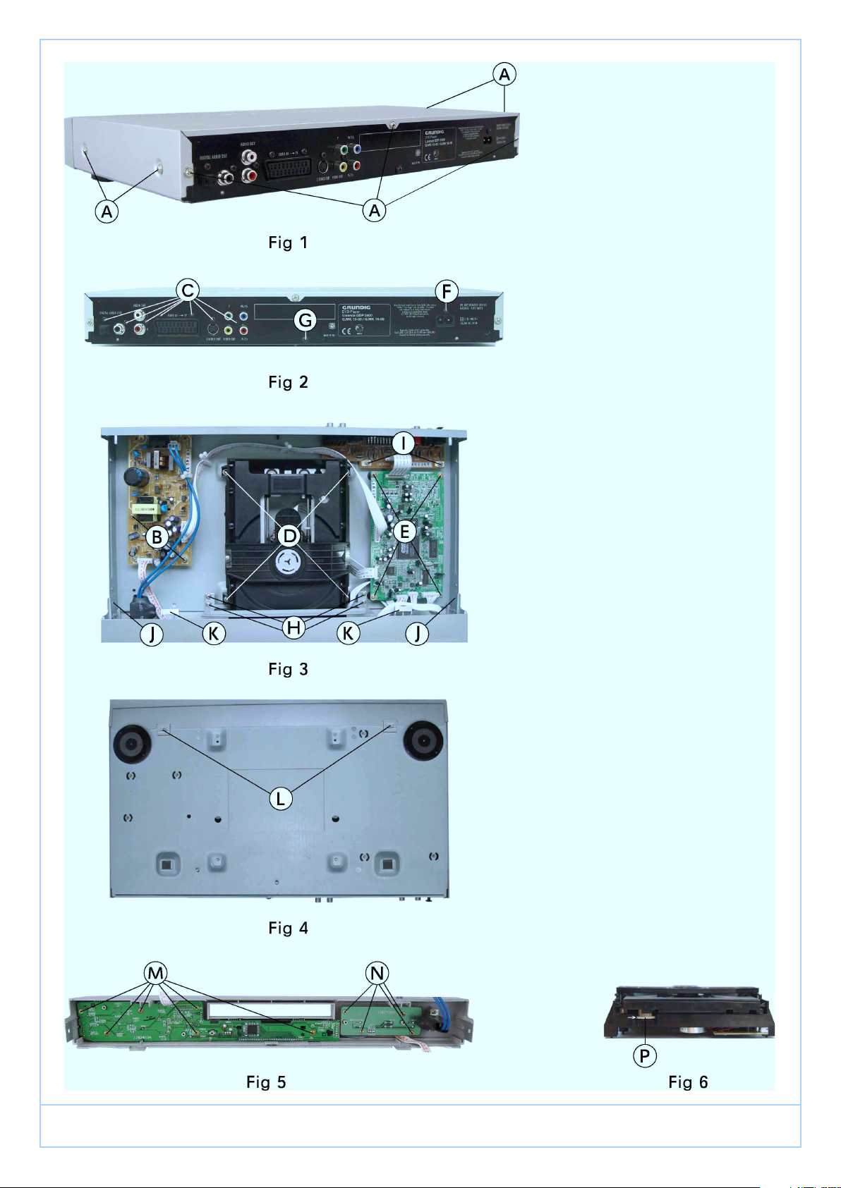
Disassembly Instructions
1. Cabinet Upper Part
– Undo the 7 screws A (Fig. 1).
– Bend the upper part of the cabinet at its centre, slide it to the
rear then remove it.
Reassembly Hint:
– Place the upper part of the cabinet on the recesses K.
2. Front Panel
– Undo the 4 locking lugs J (Fig. 3) / L (Fig. 4) and then remove
the front panel.
– Unplug the connectors if necessary.
3. VFD Driver and Key Control Board Units
– Remove the front panel (Point 2).
– Undo the 10 screws M / N (Fig. 5).
– Remove the VFD Driver and Key Control Board units.
4. Power Supply Board
– Undo the 2 screws B (Fig. 3).
– Undo the 1 screw F (Fig. 2).
– Remove the Power Supply Board from the unit.
– Unplug the connectors if necessary.
5. Main Board
– Undo the 4 screws E (Fig. 3).
– Remove the main board.
– Unplug the connectors if necessary.
6. Output Board
– Undo the 2 screws I (Fig. 3)
– Undo the 7 screws C (Fig. 2).
– Remove the output board.
– Unplug the connectors if necessary.
ǵ
7. Drive Mechanism
– Undo the 4 screws D (Fig. 3)
– Lift the drive mechanism at its back part, slide it to the rear, and
then remove it.
– Unplug the connectors if necessary.
8. Opening the Tray of a Defective Unit
– Turn the toothed wheel P (Fig. 6) in direction of the arrow until
the tray moves then pull out the tray completely.
– Remove the DVD/CD from the defective drive unit if necessary.
GDP 2400
!
!
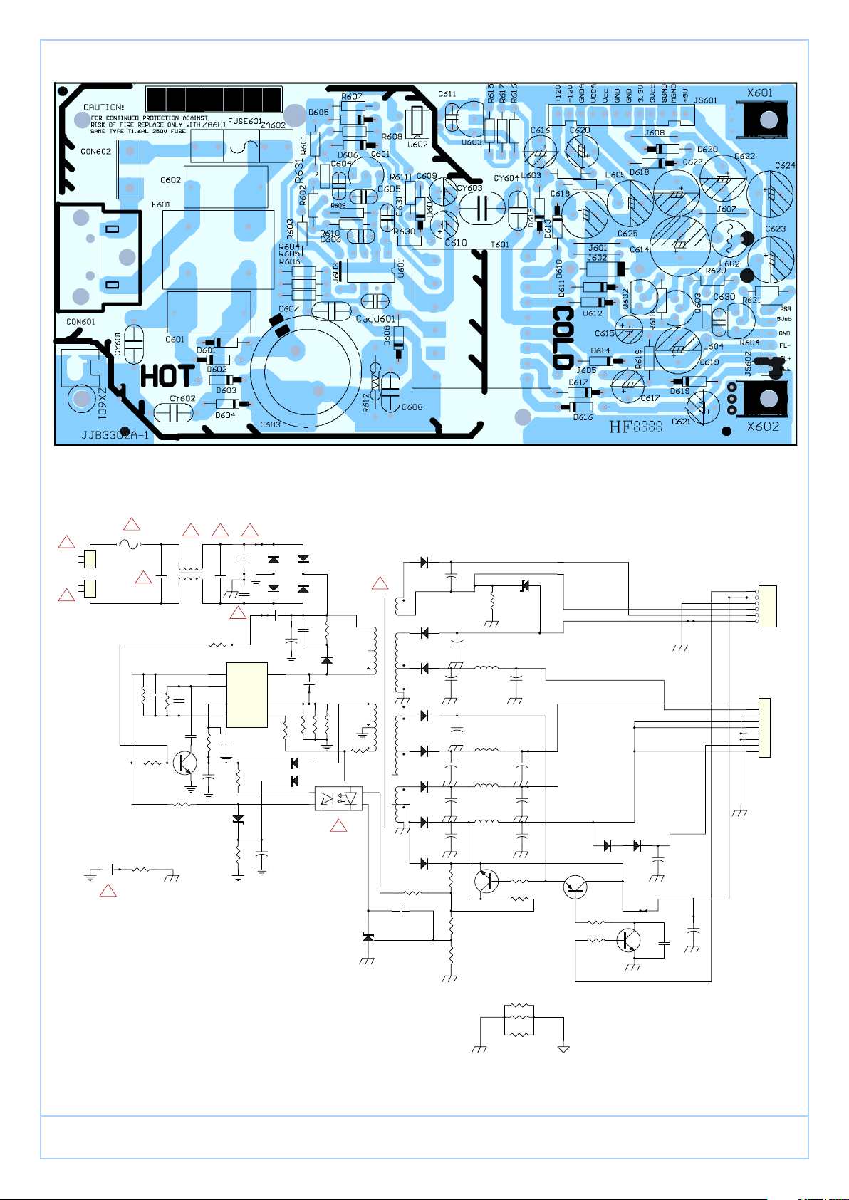
Component_1
1
2
1
2
CON602
POWER SW
CON601
AC I NPUT
CY603
222/2KV
!
!
FUSE601
T1.6AL /250V
0.1u/250V
R610
4.7K
CY604
0 OHM
C602
!
C606
100nF
560P(OPEN)
R602
56K(OPEN)
BC337-40(OPEN)
Q601
R609
6.8K
LC20-001
C605
470P
C604
R631
10 OHM
! !
F601
R630
10K
C6010.1u/250V
R603
3.3M(O PEN)
4
3
1
2
C610
+
10uF/50V
D606
BZX 79C16V
!
U601
REG
RC
VCC
GND
TEA 1523P
C631
220nF
R611
1K
R608
22K
!
CY602
102(OPEN)
CY601
102(OPEN)
472/1KV (OPEN)
Drai n
Source
AUX
+
D601
1N4001
D602
1N4001
C607
C603
68uF/400V
8
6
5
C609
10uF/50V
R601
75K
+
D604
1N4001
D603
1N4001
C608
472/1KV
cadd601
560P(open)
R6041R6051R606
D607
FR104
D605
FR104
R612
120K/1W
D608
FR107
1(OPEN)
!
PC817
R607
100
U602
T601
0
U603
TL431
D617
220uF/25V
FR104
+
!
C617
D616
FR107
D615
FR107
D612
FR107
D613
FR107
D610
IN5822
D611
FR104(OPEN)
C611
100nF
R617
1K
2200uF/16V
+
D614
FR157(OPEN)
C614
j602
0 OHM
C621
+
100uF/50V
220uF/25V
C616
C615
+
2.2u/50V
+
C618
220uF/25V
C619
+
470uF/25V(OPEN)
+
R616
5.6K
R615
5.1K
L60 5
5.6u
L60 4
5.6u(OPEN)
L60 2
R619
33K
L60 3
5.6u
C625
220uF/25V
470uF/25V(OPEN)
10u
C627
1000uF/16V
Q602
BC337-40
D619
BZX 79C9V1
C620
+
220u/25V
C624
R618
3.3K
j601
0 ohm(open)
JS602
PSB
1
5VSB
2
GND
3
FL-
4
FL+
5
VEE
6
HEAD ER 6
JS601
+12v
1
-12v
2
GNDA
3
VCCA
4
VCC
5
GND
6
GND
7
3.3V
8
SVCC
+
+
+
RL205
Q603
BC327-40
R620
470
R621
33K
D618
D620
RL205
C622
470uF/25V
Q604
BC337-40
+
470uF/25V
100NF
C630
C623
+
9
9 HEAD ER
ǵ
X601
X602
ZX601(O PEN)
GDP 2400
ǵ
GDP 2400
 Loading...