

Page 1
Service Manual
HiFi
Grundig Service
Hotline Deutschland...
Technik:
TV/SAT
VCR/LiveCam
HiFi/Audio
Car Audio
T elekommunikation
Fax:
Ersatzteil-Bestellannahme:
Telefon:
Fax:
...Mo.-Fr. 8.00-16.30 Uhr
0180/52318-41
0180/52318-42
0180/52318-43
0180/52318-44
0180/52318-45
0180/52318-51
0180/52318-40
0180/52318-50
CF 21
Service
Manual
CF 21
Sach-Nr./Part No.
72010-755.60
DOLBY B - C NR HX PRO
POWER
MEMOB-C NR INFO REC RECORD/MUTE
0-SET
Zusätzlich erforderliche
Unterlagen für den Komplettservice
Additionally required
Service Manuals for the Complete Service
Service
Manual
Sicherheit
Safety
Sach-Nr./Part No.
72010-800.00
HIFI SINGLE CASSETTE DECK CF21
IR SENSOR BALANCE REC LEVEL
REC
LEFT RIGHT
Btx * 32700 #
Sachnummer
Part Number 72010-755.60
Änderungen vorbehalten
Subject to alteration
Printed in Germany
VK231 1097
Page 2

Allgemeiner Teil / General Section CF 21
Es gelten die Vorschriften und Sicherheitshinweise gemäß dem Service Manual "Sicherheit",
Sach-Nummer 72010-800.00, sowie zusätzlich
die eventuell abweichenden, landesspezifischen
Vorschriften!
j
Inhaltsverzeichnis
Seite
Allgemeiner Teil ............................ 1 - 2 … 1 - 8
Meßgeräte / Meßmittel ............................................................... 1 - 2
Technische Daten ..................................................................... 1 - 3
Servicehinweise ........................................................................ 1 - 3
Bedienhinweise.......................................................................... 1 - 4
Ausbauhinweise......................................................................... 1 - 6
Einstellvorschriften.........................2 - 1 ... 2 - 6
Schaltpläne
und Platinenabbildungen ........... 3 - 1 … 3 - 12
Verdrahtungsplan....................................................................... 3 - 1
Schaltpläne:
Audio-Platte............................................................................ 3 - 3
Logikplatte, Displayplatte, Tastenplatten ............................... 3 - 7
Platinenabbildungen:
Logikplatte ............................................................................ 3 - 10
Audio-Platte.......................................................................... 3 - 11
Displayplatte, Potentiometerplatte, Tastenplatten................ 3 - 12
The regulations and safety instructions shall be
valid as provided by the "Safety" Service Manual,
part number 72010-800.00, as well as the
respective national deviations.
k
Table of Contents
Page
General Section............................. 1 - 2 … 1 - 8
Test Equipment / Aids................................................................ 1 - 2
Technical Data .......................................................................... 1 - 3
Service Hints............................................................................. 1 - 3
Operating Instructions................................................................ 1 - 5
Disassembly Instructions ........................................................... 1 - 6
Adjustment Procedures..................2 - 3 ... 2 - 6
Circuit Diagrams
and Layout of the PCBs.............. 3 - 1 … 3 - 12
Wiring Diagram ......................................................................... 3 - 1
Circuit Diagrams:
Audio Board ........................................................................... 3 - 3
Logic Board, Display Board, Button Boards........................... 3 - 7
Layout of PCBs:
Logic Board .......................................................................... 3 - 10
Audio Board ......................................................................... 3 - 11
Display Board, Potentiometer Board, Button Boards ........... 3 - 12
Ersatzteillisten und
Explosionszeichnungen ............... 4 - 1 … 4 - 3
CF 21 ......................................................................................... 4 - 1
Laufwerk CFF 414 ..................................................................... 4 - 3
Allgemeiner Teil
Meßgeräte / Meßmittel
Trenntrafo
Klirranalysator NF-Generator
Frequenzzähler Tonhöhenschwankungsmesser
DC-Voltmeter NF-Voltmeter
Testcassette 448 A Sach-Nr. 35079-023.00
Drehmomentcassette 456 Sach-Nr. 35079-014.00
Bandlaufcassette MC-112C Sach-Nr. 72008-247.00
Kopflehre 401 Sach-Nr. 72008-401.00
Beachten Sie bitte das GRUNDIG Meßtechnik-Programm, das Sie
unter folgender Adresse erhalten:
Spare Parts Lists
and Exploded Views ..................... 4 - 1 … 4 - 3
CF 21 ......................................................................................... 4 - 1
Drive Mechanism CFF 414 ........................................................ 4 - 3
General Section
Test Equipment / Aids
Isolating Transformer
Distortion Analyzer AF Generator
Frequency Counter Wow and Flutter Meter
DC Voltmeter AF Voltmeter
Testcassette 448 A Part No. 35079-023.00
Cassette torque meter 456 Part No. 35079-014.00
Tape transport test cassette MC-112C Part No. 72008-247.00
Head gauge 401 Part No. 72008-401.00
Please note the Grundig Catalog “Test and Measuring Equipment”
obtainable from:
GRUNDIG Instruments
Test- und Meßsysteme GmbH
Würzburger Str. 150, D-90766 Fürth/Bay
Tel. 0911/703-4118, Fax 0911/703-4130
1 - 2 GRUNDIG Service
GRUNDIG Instruments
Test- und Meßsysteme GmbH
Würzburger Str. 150, D-90766 Fürth/Bay
Tel. 0911/703-4118, Fax 0911/703-4130
Page 3

CF 21 Allgemeiner Teil / General Section
Technische Daten
Frequenz-Bereich (DIN 45500)
(Wiedergabe, IEC II) .............................................. 30Hz - 18.000Hz
Geräuschspannungsabstand
(ohne, mit Dolby B/C IEC wtd., CR) ..................... 57dB, 65dB, 73dB
(ohne, mit Dolby B/C IEC wtd., FE) ..................... 56dB, 64dB, 72dB
Gleichlauf-Schwankungen (IEC wtd.) ............................... < 0,13%
Stereo-Übersprechen (1kHz) ............................................... > 60dB
Eingangsspannung/Eingangswiderstand ........ 115mV/270kOhm
Ausgangsspannung/Ausgangswiderstand ....... 750mV/2,2kOhm
Netzspannung, Netzfrequenz................................230V~, 50/60Hz
Leistungsaufnahme .............................................................. < 15W
Dolby Rauschunterdrückung und HX-Pro headroom extension hergestellt unter Lizenz von Dolby Laboratories Licensing Corporation.
HX Pro entstand bei Bang & Olufsen.
DOLBY, das Doppel-D-Symbol g und HX PRO sind Warenzeichen
der Dolby Laboratories Licensing Corporation.
NR = Noise Reduction (Rauschunterdrückung).
Technical Data
Frequency range (acc. DIN 45500)
(Playback, IEC II) ..................................................30Hz ... 18,000Hz
Signal-to-noise ratio
(without, with Dolby B/C IEC weighted, CR) ........ 57dB, 65dB, 73dB
(without, with Dolby B/C IEC weighted, FE)......... 56dB, 64dB, 72dB
Wow & Flutter (IEC wtd.) .................................................... < 0.13%
Stereo Crosstalk (1kHz) ....................................................... > 60dB
Input voltage/impedance .................................... 115mV/270kOhm
Output voltage/impedance .................................. 750mV/2.2kOhm
Mains voltage, mains frequency...........................230V~, 50/60Hz
Power consumption.............................................................. < 15W
Dolby noise reduction and HX Pro headroom extension manufactured
under license from Dolby Laboratories Licensing Corporation. HX Pro
originated by Bang & Olufsen.
„DOLBY“, the double D Symbol g and „HX PRO“ are trademarks of
Dolby Laboratories Licensing Corporation.
NR = Noise Reduction.
Servicehinweise
Cassettenteil
Überprüfen Sie vor Beginn der Service-Arbeiten, ob die Magnetköpfe,
die Tonwelle und die Gummiandruckrolle frei von Bandabrieb sind.
Zum Reinigen dieser Teile verwenden Sie ein mit Spiritus oder Reinigungsbenzin getränktes Wattestäbchen; dadurch verbessert sich der
Aufnahme- und Wiedergabepegel, sowie der Bandlauf.
Nach dem Ersatz von Magnetköpfen oder sonstiger Bauteile müssen
die technischen Daten des Gerätes anhand der im Service Manual
vorgegebenen Meßwerte überprüft bzw. eingestellt werden.
Testmodus: E2PROM Test
Tasten "RECORD" und "Q" gedrückt halten und Gerät einschalten.
Es leuchten nacheinander die Segmente des Displays –> alle Displaysegmente werden angezeigt –> Testmodus stoppt.
Bei Fehlererkennung zeigt das Display "Erro" und stoppt den Testmodus.
Durch Ausschalten des Gerätes wird der Testmodus beendet.
Notizen / Notes
Service Hints
Cassette Section
Before commencing service work, ensure that the magnetic heads, the
capstan and the pinch roller are free from particles produced by tape
abrasion. The recording and playback levels and the tape run can be
improved by cleaning these parts with a cotton-wool tip soaked in spirit
or cleaning benzine.
If the heads or other components have been replaced, the technical
data of the recorder must be checked or adjusted according to the
values specified in the Service Manual.
Testmode: E2PROM Test
Hold the buttons "RECORD" and "Q" depressed and switch on the
unit.
The segments of the display light up successively –> all display
segments illuminate –> test mode stops.
A defect is indicated in the display by the message "Erro" and the test
mode is stopped.
The Testmode is finished by switching off the unit.
GRUNDIG Service 1 - 3
Page 4
Allgemeiner Teil / General Section CF 21
1 - 4 GRUNDIG Service
Bedienhinweise
Dieses Kapitel enthält Auszüge aus der Bedienungsanleitung. Weitergehende Informationen entnehmen Sie bitte
der gerätespezifischen Bedienungsanleitung, deren Sachnummer Sie in der entsprechenden Ersatzteilliste finden.
D
Vorderseite des Kassettendecks
POWER Dieser Schalter wird zum Ein- und Ausschalten des Geräts verwendet.
9 Mit dieser Taste beenden Sie alle Funktionen.
QR
Gerät befindet sich in STOP: schneller Rück- oder Vorlauf.
Aus Wiedergabe gedrückt: MUSIC SEARCH rückwärts (Musik-Suchlauf zum
vorherigen Titel) oder vorwärts (Musik-Suchlauf zum nächsten Titel).
? Mit dieser Taste öffnen Sie das Kassettenfach.
B Mit dieser Taste starten Sie die Wiedergabe
; Mit dieser Taste unterbrechen Sie die Wiedergabe/Aufnahme kurzzeitig.
d B-C NR Diese Taste wählt das Rauschunterdrückungssystem.
0-SET Mit dieser Taste setzen Sie das Zählwerk auf Null zurück.
MEMO Mit dieser Taste können Sie Bandpositionen speichern.
INFO Mit dieser Taste schalten Sie zwischen den Anzeigen COUNTER
(Bandzählwerk) und TIME (Echtzeit in Sekunden und Minuten) um.
RECORD/MUTE Mit dieser Taste starten Sie die Funktion Aufnahme.
IR SENSOR Empfängt die Signale einer Systemfernbedienung.
BALANCE Hiermit stellen Sie das Verhältnis der Aufnahme-Lautstärke zwischen den
beiden Stereo-Kanälen ein.
REC LEVEL Hiermit stellen Sie den Aufnahmepegel ein.
ALLGEMEINES
Ein- und Ausschalten
•
Wollen Sie das Gerät ein- oder ausschalten,
drücken
Sie den Netzschalter POWER. Die
Betriebsanzeige,
eine gelbe Leuchtdiode in
der Mitte des Einschaltknopfes, informiert Sie
über den Schaltzustand: gedrückt: EIN,
ausgerastet: AUS.
• Wollen Sie das Gerät ausschalten, drücken
Sie den Netzschalter POWER nochmals.
• Haben Sie Ihr Gerät an die Wechselspannungs-
Ausgänge AC OUTLETS des
Verstärkers angeschlossen,
dient der
Netzschalter des Verstärkers als Zentralschalter. Lassen Sie den Schalter POWER des
Kassettendecks immer gedrückt.
– Nach dem Einschalten ist das Gerät immer im
STOP-Modus.
– Die Einstellung des d B-C NR-Schalters ist
dieselbe wie vor dem Ausschalten.
– Die letzte Stellung des Bandzählwerkes wurde
ebenfalls gespeichert.
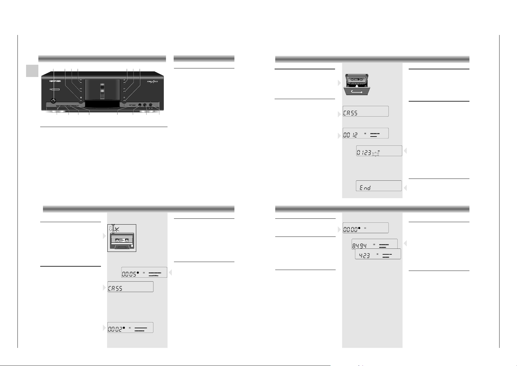
Kassette einlegen
• Mit der Taste ? öffnen Sie das Kassettenfach.
• Legen Sie die Kassette mit der offenen Seite
nach unten und der vollen Spule nach links in
der Schublade.
• Schließen Sie das Kassettenfach von hand.
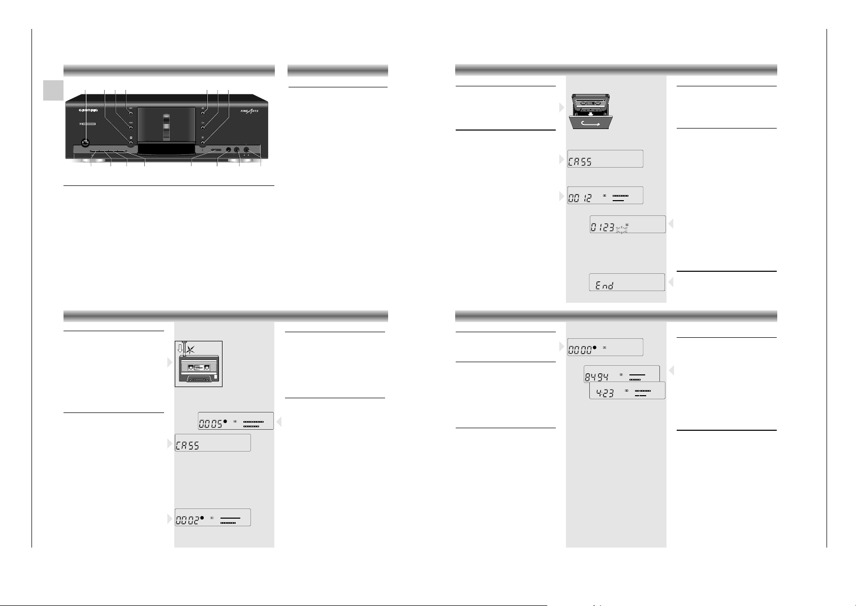
Wiedergabe
• Die Funktion B (Wiedergabe) läßt sich nur
starten, wenn Sie eine Kassette eingelegt haben.
– Betätigen Sie eine der Tasten B,
RECORD/MUTE, Q oder R, ohne eine
Kassette eingelegt zu haben, zeigt das Display
für 1,5 Sekunden
CASS
.
• Wählen Sie mit der Taste
d B-C NR
das
Rauschunterdrückungssystem, mit dem die
Kassette aufgenommen wurde.
• Drücken Sie die Taste
B, um die
Wiedergabe zu starten.
–
Die Bargraph-Anzeige im Display informiert Sie
über die Pegelspitzen der aufgenommenen Musik.
• Wollen Sie die Wiedergabe kurzzeitig
unterbrechen, drücken Sie die Taste ;
(PAUSE).
Das ; Symbol leuchtet.
• Wollen Sie mit der Wiedergabe fortfahren,
drücken Sie die Taste
B erneut.
Das ; Symbol erlischt.
– Am Bandende wird das Band gestoppt.
• Drücken Sie auf
9, wenn Sie das Band vor
dem Bandende stoppen möchten.
WIEDERGABE
Schneller Vor-/Rücklauf einer Kassette
Diese Funktionen sind nur aus STOP heraus möglich.
• Drücken Sie auf Q oder R .
– Der Schnellauf wird in der gewählten Richtung
gestartet und das Display zeigt Q oder R.
• Beenden: Taste 9 drücken.
Funktion MUSIC SEARCH
Die Tasten Q und R ermöglichen die
direkte Anwahl von Titeln einer Kassette durch
Überspringen eines oder mehrerer Titel. Während
der Wiedergabe kann durch kurzes Drücken der
Tasten QRdirekt auf ein bestimmtes Stück
zugegriffen werden. Bis zu 15 Titel können in
beide Richtungen übersprungen werden.
• Drücken Sie einmal
R, spult das Gerät bis
an den Anfang des nächsten Titels.
Drücken Sie
einmal Q, spult das Gerät
bis an den
Anfang des aktuellen Titels zurück.
• Drücken Sie die Taste R zweimal, so wird
der zweite Titel in Vorwärtsrichtung gesucht,
drücken Sie die Taste dreimal, wird das dritte
Musikstück gesucht (max. 15 Titel).
–
Das Gerät schaltet auf Schnellauf zum gewählten
Titel und die Wiedergabe startet automatisch.
Voraussetzung ist, daß zwischen den einzelnen
Stücken Pausen von jeweils 4 Sekunden
aufgenommen wurden.
Hinweis: Bei Titeln mit extrem leisen
Musikpassage
n kann es vorkommen, daß diese
vom Musik-Suchlauf als Pausen erkannt werden.
Abschalten am Bandende
Aus allen Lauffunktionen schaltet das Laufwerk am
Bandende auf 'STOP'.
• Versuchen Sie am Bandende die Wiedergabe
oder den Bandschnellauf in die falsche
Richtung zu starten, zeigt das Display END.
B
+80-6-12-18 +4dB
L
R
B
R
B
+80-6-12-18 +4dB
L
R
B
Kassette gegen Löschen schützen
Bei jeder Aufnahme wird die vorherige
Aufzeichnung überspielt.
Selbstbespielte Kassetten können Sie gegen
versehentliches Löschen schützen, indem Sie die
entsprechende Sicherungsnase aus der Öffnung
im Kassettenrücken brechen, z.B. mit einem
Schraubenzieher.
Bespielt gekaufte Kassetten (Musik-Kassetten) sind
bereits gegen versehentliches Löschen gesichert.
Wollen Sie eine gesicherte Kassette neu
bespielen, überkleben Sie die entsprechende
Öffnung mit Klebeband.
Vorbereiten der Aufnahme
Copyright: Aufzeichnungen sind insoweit erlaubt,
als dadurch das Copyright oder andere Rechte
Dritter nicht verletzt werden.
Bei Kassetten mit Löschsicherung ist die Aufnahme
gesperrt, das Display zeigt für 1,5 Sekunden
CASS und sperrt die Aufnahme.
• Legen Sie eine ungeschützte Kassette in die
Schublade un spulen Sie bis zu der
gewünschten Bandstelle.
• Schalten Sie das Rauschminderungs-System mit
d B-C NR ein.
– Das Display informiert Sie über die gewählte
Einstellung.
• Wählen Sie am Verstärker oder Receiver die
Signalquelle, von der Sie aufnehmen möchten.
• Drücken Sie die Taste RECORD/MUTE:
– Das Gerät schaltet auf 'Aufnahme-Pause'.
– Die rote LED REC leuchtet.
–
Die Anzeigen REC und ; leuchten im Display auf.
– Die Bargraphanzeige im Display zeigt den
Aufnahmepegel den Sie mit dem Regler REC
LEVEL einstellen können.
AUFNAHME
;
REC
B
+80-6-12-18 +4dB
L
R
REC
B
+80-6-12-18 +4dB
L
R
B
MEMO
1
Einstellen des Aufnahmepegels
Eine Aufnahme sollte richtig ausgesteuert sein.
Dies bedeutet, an den lautesten Passagen der
Aufnahme die Pegelanzeige (dB) im Display bis
'0' dB (=100% Aussteuerung) aufleuchten darf.
• Mit dem Einsteller REC LEVEL stellen Sie den
richtigen Aufnahmepegel ein.
• Pegelunterschiede zwischen dem linken und
dem rechten Kanal können Sie mit Hilfe des
Einstellers BALANCE ausgleichen.
Beginn der Aufnahme
• Drücken Sie die Taste B um die Aufnahme zu
starten.
–
Die Anzeigen REC und B leuchten im Display auf.
– Die rote LED REC leuchtet.
• Falls gewünscht drehen Sie den Einsteller REC
LEVEL zum Ausblenden der Musik langsam
nach links und zum Einblenden nach rechts in
die Position des jeweils gewünschten
Aufnahmepegels.
• Wollen Sie die Aufnahme unterbrechen,
drücken Sie die Taste ;.
Das ; Symbol leuchtet.
– Das Gerät befindet sich nun im RECORD
PAUSE-Modus.
• Drücken Sie die B-Taste erneut, wenn Sie die
Aufnahme fortsetzen möchten.
– ; erlischt und die Anzeige B leuchtet wieder.
– Das Gerät stoppt den Aufnahmevorgang
automatisch, wenn das Bandende erreicht ist.
•
Vorzeitig beenden: Drücken Sie die Taste 9.
WEITERE LEISTUNGSMERKMALE
Zurücksetzen des Zählwerkes
• Drücken Sie z. B. am Beginn einer Aufnahme
die Taste 0-SET, um den Zählerstand auf Null
zurückzusetzen.
Speichern von Bandpositionen
• Durch drücken der Taste MEMO, können Sie
die momentane Bandposition speichern.
– Im Display erscheint das Zeichen MEMO.
• Betätigen Sie dann im STOP-Betrieb die Taste
Q (schneller Rücklauf), spult das Gerät
zurück und stoppt an der entsprechenden
Stelle.
• Drücken Sie die Taste MEMO erneut, beenden
Sie die Funktion.
Aufnahmepause RECORD MUTE
Um mit der Funktion MUSIC SEARCH Musiktitel
gezielt auffinden zu können, müssen Sie eine
Aufnahmepause von 4 Sekunden zwischen den
einzelnen Titeln aufzeichnen.
• Drücken Sie dazu am Ende des Titels die Taste
RECORD/MUTE einmal kurz.
– Die rote LED (REC) blinkt für die Dauer von 4
Sekunden.
– Das Gerät erzeugt eine vier Sekunden lange
Aufnahmepause und wartet dann, bis Sie mit
der Aufnahme fortfahren (RECORD PAUSE).
• Starten Sie die Aufnahme erneut in derselben
Laufrichtung mit
B .
• Halten Sie die Taste RECORD/MUTE länger
gedrückt, dauert die Aufnahmepause so lange,
wie Sie die Taste gedrückt halten.
• Lassen Sie die Taste los, wartet das Gerät
wiederum in Aufnahmepause.
– Die blinkende rote LED informiert Sie über die
Länge der Pause.
R
➥
➥
+80-6-12-18 +4dB
L
B
B
+80-6-12-18 +4dB
L
R
B
B
;
REC
B
+80-6-12-18 +4dB
L
R
MEMO
Umschalten von Bandzählwerk auf
Echtzeit
• Mit der Taste INFO schalten Sie zwischen
Bandzählwerk und Anzeige der Echtzeit
(Minuten und Sekunden) um.
Abstimmung der Echtzeitanzeige
Die Echtzeitmessung muß sich erst auf die Dicke
des verwendeten Bandmaterials in der Kassette
einstellen.
Starten Sie z. B. die Wiedergabe, blinkt der
Doppelpunkt zwischen der Sekunden- und
Minutenanzeige (-:--) für einige Zeit.
Während dieser Zeit werden die Banddicke und
andere Werte berechnet. Ist dieser Vorgang
abgeschlossen, läuft die Anzeige der Echtzeit
auch bei schnellem Vor- und Rücklauf mit.
Pflege des Gerätes
• Gehäuse mit weichem, staubbindendem
Lappen reinigen.
• Polier- und Reinigungsmittel könnten die
Oberfläche des Gehäuses beschädigen.
Bandberührende Teile wie Andruckrolle,
Tonwelle, Tonkopf und Löschkopf müssen frei
von Bandabrieb sein, um eine gleichbleibend
gute Aufnahme und Wiedergabe zu erreichen.
• Diese Teile sollten Sie in regelmäßigen
Abständen reinigen.
• Verwenden Sie dazu eine spezielle
Reinigungskassette.
• Verwenden Sie keine harten oder
magnetischen Gegenstände!
BEDIENELEMENTE
REC
HIFI SINGLE CASSETTE DECK CF21
LEFT RIGHT
DOLBY B - C NR HX PRO
POWER
0-SET
MEMOB-C NR INFO REC RECORD/MUTE
IR SENSOR BALANCE REC LEVEL
POWER
INFO
9 QR ? B ;
0-SET MEMO REC LEVELRECORD/MUTE IR SENSOR BALANCE
d B-C NR
Page 5
CF 21 Allgemeiner Teil / General Section
GRUNDIG Service 1 - 5
Operating Instructions
This chapter contains excerpts from the operating instructions. For further particulars please refer to the
appropriate user instructions the part number of which is indicated in the relevant spare parts list.
GB
Front of the cassette deck
POWER To switch the cassette deck on and off.
9 To stop all functions.
QR
When the unit is in STOP mode: fast winding forward or backward.
When pressed during playback: MUSIC SEARCH forward (music search to the begin
-
ning of next tracks) or backward (music search to the beginning of the previous tracks).
? Opens the cassette compartment.
B To start playback.
; To switch the cassette deck to PAUSE.
d B-C NR To select the noise reduction system.
0-SET For setting the tape counter to zero.
MEMO This button is used for storing a tape position.
INFO This button is used for switching between the COUNTER (tape counter) and TIME (real
time in minutes and seconds) display.
RECORD/MUTE To start the recording function.
IR SENSOR To receive signals from a system remote control.
BALANCE This is used to adjust the sound balance between both stereo channels when
recording.
REC LEVEL For setting the recording level.
REC
HIFI SINGLE CASSETTE DECK CF21
LEFT RIGHT
DOLBY B - C NR HX PRO
POWER
0-SET
MEMOB-C NR INFO REC RECORD/MUTE
IR SENSOR BALANCE REC LEVEL
POWER
INFO
9 QR ? B ;
0-SET MEMO REC LEVELRECORD/MUTE IR SENSOR BALANCE
d B-C NR
Switching on and off
• When you want to switch your cassette deck
on, press the POWER button. The yellow light
in the middle of the button indicates that the
unit is on.
button depressed: POWER ON
button not depressed: POWER OFF
• When you want to switch the unit off, simply
press the POWER button again.
•
If the mains plug of your cassette deck is
connected
to one of the AC OUTLETS on the
amplifier, the
POWER button of the amplifier
serves as the central
switch for all units
connected to the AC OUTLETS.
– After switching on, your unit is always in the
STOP mode. The d B-C NR switch remains in
the setting it was in when the unit was
switched off. The last tape counter position is
also stored.
GENERAL
PLAYBACK
Fast winding
These functions are only possible when in the
STOP mode.
• Press Q or R.
– The winding starts in the selected direction and
the indication Q or R lights up on the
display.
• To stop: press 9.
MUSIC SEARCH function
The Q and R keys also enable you to select
directly a desired track on a cassette by skipping
one or more tracks. This can be done by briefly
pressing the QRkeys during playback. Up
to 15 tracks can be skipped in each direction.
• If you press R once, the tape will wind to
the beginning of the next track. If you press
Q once, the tape will rewind to the
beginning of the current track.
• If you press R twice, the tape will advance
to the second track in forward direction,
pressing three times advances to the third
track, and so on to a max. of 15 tracks.
– The tape will wind to the beginning of the
selected track and playback will start
automatically.
The only requirement for this function is a 4second pause between each of the tracks.
Note: On some music tapes, the search function
may recognize extremely quiet passages as pauses.
Stop at the end of the tape
At the end of a tape, the cassette deck
automatically switches to "STOP."
• If you, being at the end of the tape, attempt to
start playback or fast winding in the wrong
direction, END is shown in the display.
Inserting a cassette
• Press the ? button to open the cassette
compartment.
• Insert the cassette, with the open side down,
and the full spool to the left into the
compartment.
• Close the cassette compartment by hand.
Playback
• Playback B can only be started if there is a
cassette in the cassette compartment.
– If you press B, RECORD/MUTE, Q
or R and the compartment is empty,
CASS
appears on the display for 1.5 seconds
.
•
With d B-C NR, select the noise reduction system
with which the cassette recording was made.
• Press B to start playback.
– The bargraph in the display shows the sound
level of the recorded music.
• If you want to briefly interrupt playback, simply
press
; (PAUSE).
– The ; indication on the display lights up.
• If you want to continue playback, press B
again.
– The ; indication goes out.
– The deck plays one cassette side and stops
automatically at the end.
• If you want to stop the tape before it reaches
the end, simply press
9.
Protecting cassettes against
unintentional erasure
Every time you record onto a tape, its contents is
erased and replaced by the new recording.
In order to avoid unintentional erasure of a
recording, carefully remove its safety tabs with,
for example a screw driver.
Original recordings are already protected
against unintentional erasure.
If you wish to record on a 'protected' cassette,
place a small strip of tape over the corresponding holes.
Preparing to record
Copyright: Making recordings from a prerecorded sound track is only permissible insofar as the
Copyright or the rights of third parties are not
infringed upon.
Recording on protected cassettes is not possible,
CASS appears in the display for 1.5 seconds,
and recording is prevented.
• Insert an unprotected cassette in the cassette
compartment and wind to the desired tape
position.
• Switch on the noise reduction system with
d B-C NR.
– The display indicates the selected setting.
• Select on the amplifier or receiver the source
from which you want to record
• Press RECORD/MUTE: the unit switches to
‘RECORD PAUSE’
– The red REC LED lights up.
–
The display shows the REC and ; indications.
– The Bargraph indication on the display shows
recording level which can be adjusted with the
REC LEVEL control.
RECORDING
;
REC
B
+80-6-12-18 +4dB
L
R
REC
B
+80-6-12-18 +4dB
L
R
B
MEMO
1
Recording level adjustment
The recording level of your recording should be
properly adjusted.
This means that the loudest passages should not
exceed "0" in the recording level (dB) bargraph
display (= 100% modulation).
• You can set the correct recording level with the
REC LEVEL controller.
• Recording level differences between the left
and right channels can be corrected with the
BALANCE controller.
Starting a recording
• Press B to start the recording.
–
The display shows the REC and B indications.
– The red REC LED lights up.
• If desired you can fade a recording out, by
slowly turning the REC LEVEL counter clockwise; to fade a recording in turn clockwise to
the desired recording level.
• To interrupt the recording , press
;.
The ; symbol lights up.
–
The unit is now in the ‘RECORD PAUSE’ mode.
• If you want to resume the recording press B
again.
– ; goes out and B lights up again.
– The unit automatically stops recording when
the end of the first side of the cassette is
reached.
• Press
9 to stop recording at an earlier point.
Resetting the tape counter
• Press the 0-SET button, for example at the
beginning of a recording, to reset the tape
counter to 0.
Storing tape positions
• You can store the current tape position by
pressing MEMO.
– The indication MEMO appears in the display.
• When you press Q (in stop mode), the
cassette deck rewinds and stops at the stored
position.
• Pressing MEMO again ends this function.
Recording pause with RECORD MUTE
In order to find a track with the MUSIC SEARCH
function, there must be a 4-second recording
pause between the individual tracks.
• Therefore, briefly press RECORD/MUTE once
at the end of a track.
– The red indicator REC flashes for 4 seconds.
– The unit generates a 4-second recording pause
and waits for you to resume recording
(RECORD PAUSE).
• Resume recording by pressing
B.
• If you keep RECORD/MUTE pressed longer,
the recording pause will last as long as you
keep the button pressed.
• When you release the button, the unit waits in
recording pause.
– The flashing red indicator indicates the length
of the pause.
OTHER FEATURES
R
➥
➥
+80-6-12-18 +4dB
L
B
B
+80-6-12-18 +4dB
L
R
B
B
;
REC
B
+80-6-12-18 +4dB
L
R
MEMO
Switching from the tape counter to
the real time display
• You can use the INFO button to switch
between the tape counter and the real time
display (minutes and seconds).
Calculation of the time
When you begin playback with real time
display, the colon between the minutes and
seconds field (-:--) briefly blinks.
During this time the tape thickness and other
values are calculated. When this process is
concluded, the real time is displayed.
After this, the displayed time is also correct during
fast forward and fast reverse winding.
Caring for the unit
• Wipe the housing clean with a soft, antistatic
cloth.
• Never use cleaning agents which contain
alcohol, methylated spirits, ammonia or
abravises.
To ensure consistent recording and playback
quality, you should clean playback and
recording heads, the capstan, and the capstan
idlers regularly.
• Use a special cleaning cassette.
• In the case of malfunction, refer to your
specialized dealer.
OPERATING ELEMENTS
L
B
B
R
L
B
B
R
R
+80-6-12-18 +4dB
+80-6-12-18 +4dB
Page 6
Allgemeiner Teil / General Section CF 21
Ausbauhinweise
Allgemeines zum mechanischen Teil.
Die Zahlen im Text und bei den Abbildungen sind mit den Positionsnummern der Zeichnungen in der Ersatzteilliste CFF 414 identisch.
Vor Beginn von Servicearbeiten ist das Gerät in die Funktion "STOP"
zu bringen, der Kopfschlitten ist dann zurückgefahren.
Mechanische Beschädigungen der Bandlaufflächen und Führungen
können dadurch vermieden werden.
Um bei mechanischen Arbeiten elektrische Bauteile nicht zu zerstören, ist nach zurückgefahrenem Kopfschlitten der Netzstecker aus der
Steckdose zu ziehen.
Alle Schrauben, die in Kunststoff eingedreht werden, sollten zuerst
soweit gegen den Uhrzeigersinn gedreht werden, bis Sie merken, die
Schraube hat den Gewindeanfang gefunden. Erst dann ist die Schraube festzudrehen. Dadurch wird vermieden, daß ein neues Gewinde
in den Kunststoff geschnitten wird und der Halt der Schraube verlorengeht.
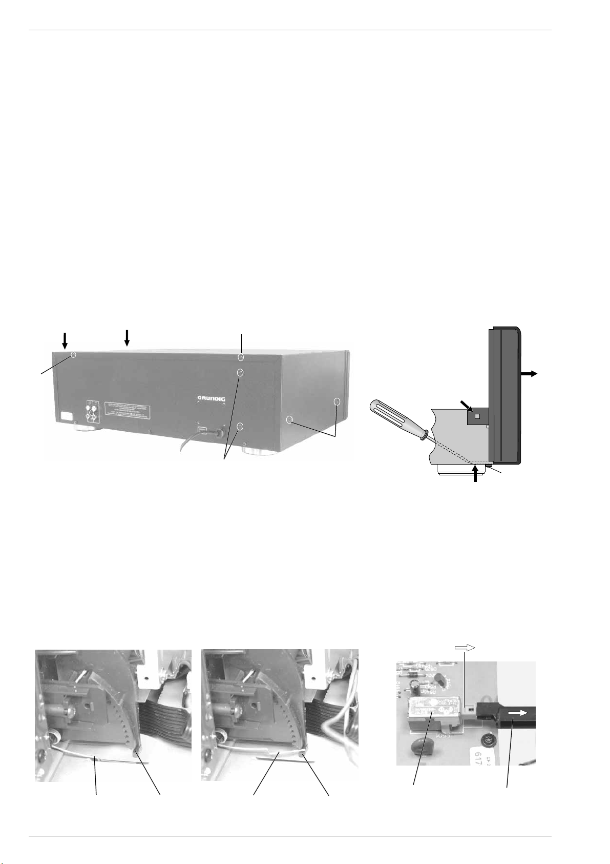
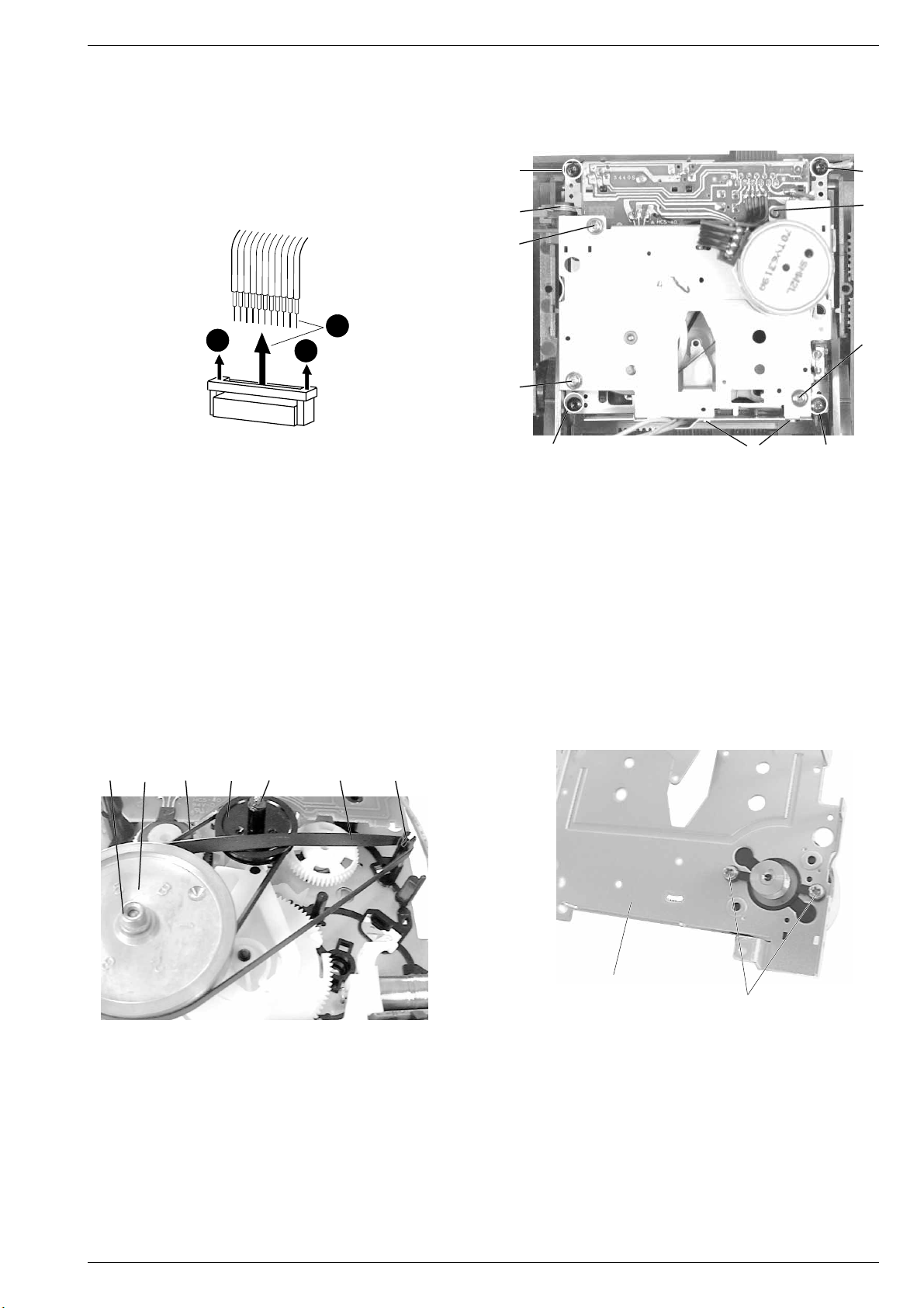
1. Öffnen des Gehäuses
- 6 Schrauben A herausdrehen (Fig. 1).
- Gehäuseoberteil hinten anheben und abnehmen.
A
A
A
Disassembly Instructions
General Notes on the Mechanical Section.
The numbers in the text and in the diagrams are the same as the
position numbers of the exploded views included in the spare parts
list CFF 414.
Before starting repair works set the tape deck to "STOP" position so
that the head carrier is in service position in order to avoid mechanical
damages to the surfaces contacting the tape and the guides.
With the head carrier in service position disconnect the mains plug to
ensure that the electrical components are not damaged during the
mechanical repair works.
All the screws which are screwed into plastic parts should be turned
counter clockwise first until you notice that the screw has found the first
thread. Then tighten the screw. This preventive measure ensures that
no new threads are cut into the plastic material thus deteriorating the
good fit of the screw.
1. Opening the Cabinet
- Undo 6 screws A (Fig. 1).
- Raise the cabinet top on the rear side and remove.
A
Trafo-Schrauben
Trafo Screws
Fig. 1
2. Frontblende (mit Leiterplatten) ausbauen
- Gehäuseoberteil abnehmen (siehe Pkt. 1).
- Cassettendeckel-Drehfeder B über den Zapfen C (Fig. 3) einhängen.
- Schraube 1 (Fig. 2) am Gehäuseboden herausdrehen.
- Laschen 2 links und rechts der Frontblende sowie 3 Haltezapfen 3
am Gehäuseboden ausrasten (Fig. 2).
- Netzschalter in Stellung "Aus" bringen und danach den Netzschalterstößel D abziehen (Fig. 4).
- Frontblende mit dem Laufwerk vorsichtig nach vorne 4 abziehen
(Fig. 2).
- Bei Bedarf Steckverbindungen lösen (Fig. 5).
4
2
A
Fig. 2
2. Removing the Front Panel (with PCBs)
- Remove the top of the cabinet (see para 1).
- Attach the cassette lid torsion spring B to the lug C (Fig. 3).
- Undo the screw 1 (Fig. 2) on the bottom of the cabinet.
- Disengage the lugs 2 on the left and right of the front panel and 3
prongs 3 on the bottom of the cabinet (Fig. 2).
- Set the power switch to "Off", then disengage the push-rod D of
the power switch (Fig. 4).
- Pull the front panel with the drive mechanism carefully towards the
front 4 (Fig. 2).
- If necessary, disconnect the connectors (Fig. 5).
3
"Aus/Off"
1
Netzschalter
CB
Fig. 3
1 - 6 GRUNDIG Service
B
C
Mains Switch
Fig. 4
D
Page 7
CF 21 Allgemeiner Teil / General Section
3. Laufwerk ausbauen
- Gehäusefront abnehmen (siehe Pkt. 2).
- Drehfeder E aushängen (Fig. 6).
- 4 Schrauben F herausdrehen (Fig. 6).
- Laufwerk nach hinten herausnehmen.
Steckverbindungen
Connectors
P503, P504,
P505, P512
2
1
Fig. 5
4. Laufwerkmotor ausbauen
- Laufwerk ausbauen (siehe Pkt. 3).
- 2 Schrauben G herausdrehen und Abschirmblech abnehmen
(Fig. 6).
- 4 Schrauben H herausdrehen (Fig. 6).
- Nehmen Sie den Antriebsriemen 39 von der Motorriemenscheibe
und legen Sie ihn über den hochstehenden Bolzen I (Fig. 7).
- Laufwerkabdeckung 35 (Fig. 8) mit Motor abnehmen, achten Sie
dabei auf die Scheibe 102 (Fig. 7).
- 2 Schrauben J herausdrehen (Fig. 8), Motor herausnehmen und
ablöten.
5. Antriebsriemen auswechseln
- Die Vorarbeiten zum Auswechseln des Antriebsriemens 39 und des
Riemens 21 sind wie beim Ausbauen des Laufwerkmotors (siehe
Pkt. 4).
- Riemen auswechseln.
Achtung!
frei von Öl und Fett sein.
Riemen, Andruckrolle und Bandkontaktstellen müssen
28
21
1
10220
3927
I
3. Removing the Drive Mechanism
- Remove the front panel (see para 2).
- Unhook the torsion spring E (Fig. 6).
- Undo 4 screws F (Fig. 6).
- Take the drive mechanism out towards the rear.
F
E
F
H
H
H
H
F
Fig. 6
4. Removing the Motor of the Drive Mechanism
- Dismantle the drive mechanism (see para 3).
- Undo the 2 screws G and take out the metal shielding (Fig. 6).
- Undo 4 screws H (Fig. 6).
- Take off the drive belt 39 from the motor pulley and put it around the
upright bolt I (Fig. 7).
- Remove the cover 35 (Fig. 8) from the drive mechanism with the
motor, take care of the washer 102 (Fig. 7).
- Undo 2 screws J (Fig. 8), take the motor out and unsolder it.
5. Changing the Drive Belt
- The preparations for changing the drive belt 39 and the belt 21 are
the same as for replacing the motor of the drive mechanism (see
para 4).
- Replace the belt(s).
Warning!
the tape must be free of oil and grease.
Belts, pressure roller and parts coming into contact with
G
F
35
J
Fig. 7
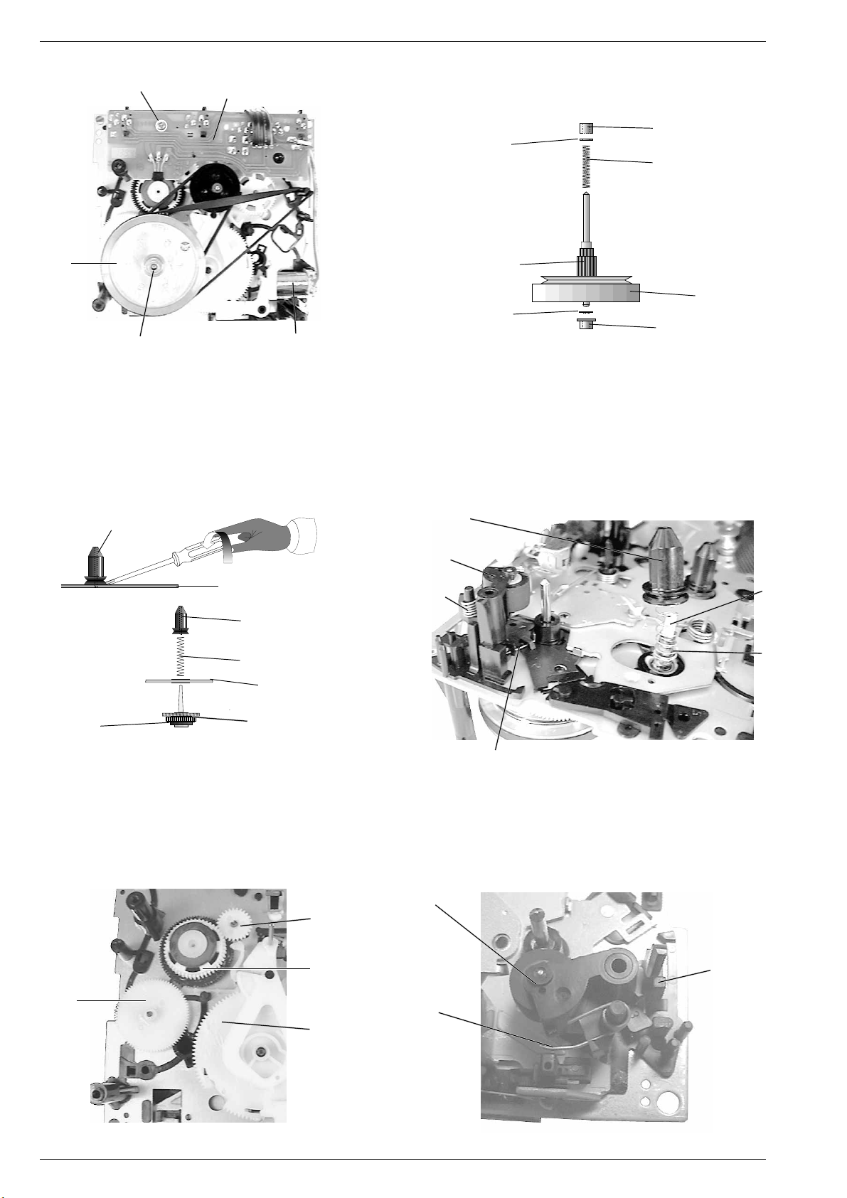
6. Laufwerkplatte ausbauen
- Laufwerkabdeckung 35 mit Motor ausbauen (siehe Pkt. 4).
- Schraube K herausdrehen (Fig. 9).
- Leitungen zum Servomagnet und Motor ablöten.
- Leiterplatte abnehmen.
7. Schwungrad auswechseln
- Laufwerkabdeckung 35 mit Motor ausbauen (siehe Pkt. 4).
- Riemen 39 und 21 abnehmen.
- Ziehen Sie das Schwungrad 27 nach hinten heraus.
Achten Sie beim Aus- und Einbau des Schwungrades auf die beiden
Lager 26, 28, die beiden Scheiben 103 und die Feder 69 (Fig. 10).
Nach dem Einbau des Schwungrades muß die Capstanwelle mit
Spiritus oder Reinigungsbenzin gereinigt werden.
GRUNDIG Service 1 - 7
6. Removing the Drive Mechanism Circuit Board
- Remove the cover of the drive mechanism 35 with motor (see para 4).
- Undo screw K (Fig. 9).
- Unsolder the leads to the servo release magnet and the motor.
- Take out the circuit board.
7. Replacing the Flywheel
- Remove the cover of the drive mechanism 35 with motor (see para 4).
- Remove the belt 39 and 21.
- Withdraw the flywheel 27 towards the rear.
When removing and refitting the flywheel take care of the two
bearings 26, 28, the two washers 103 and the spring 69 (Fig. 10).
After having fitted the new flywheel the capstan must be cleaned with
spirit or cleaning benzine.
Fig. 8
Page 8
Allgemeiner Teil / General Section CF 21
K
Laufwerkplatte
Drive mechanism pcb
27
28
Servomagnet
Fig. 9
8. Kupplungen (15, 23) ausbauen
- Laufwerkplatte ausbauen (siehe Pkt. 4).
- Schwungrad ausbauen (siehe Pkt. 7).
- Scheibe 102 und Riemenscheibe 20 abziehen (Fig. 7).
- Wickeldorn 9 aushebeln und abziehen (Fig. 11 und 12).
- Bei Bedarf das Zahnrad 18 abziehen (Fig. 13).
- Nehmen Sie die Kupplung nach hinten heraus.
26
103
69
27A
27
103
28
Fig. 10
8. Removing the Clutches (15/23)
- Remove the drive mechanism circuit board (see para 4).
- Remove the flywheel (see para 7).
- Pull off the washer 102 and the pulley 20 (Fig. 7).
- Lift off and remove the spindle 9 (Figs. 11 and 12).
- If necessary pull off the gearwheel 18 (Fig. 13).
- Remove the clutch towards the rear.
9
CHASSIS
9
VORLAUFKUPPLUNG
FORWARD CLUTCH
MAGNET
64
CHASSIS
23
Fig. 11
9. Andruckrolle auswechseln
- Laufwerk ausbauen (siehe Pkt.3).
- Untere Drehfeder 67 aushängen (Fig. 12).
- Rastnase L (Fig. 14) ausrasten und die Andruckrolle 11 mit der
Drehfeder 66 abziehen.
- Beim Einbau ist die Feder 67 (Fig. 12) wieder einzuhängen.
18
9
11
66
67
Fig. 12
9. Replacing the Pressure Roller
- Dismantle the drive mechanism (see para 3).
- Unhook the lower torsion spring 67 (Fig. 12).
- Disengage the locking lug L and pull out the pressure roller 11 with
the torsion spring 66 (Fig. 14).
- Refit the spring 67 (Fig. 12) when mounting the new pressure roller.
11
23
64
13
23
66
L
25
Fig. 13
1 - 8 GRUNDIG Service
Fig. 14
Page 9

CF 21 Einstellvorschriften / Adjustment Procedures
j
Einstellvorschriften
Meßgeräte/Meßmittel:
Frequenzzähler, NF-Voltmeter, Gleichspannungs-Voltmeter, NF-Generator, Klirranalysator, Tonhöhenschwankungsmesser,
Cr-Testcassette 448 A (Sach-Nr. 35079-023.00), Drehmomentcassette 456 (Sach-Nr. 35079-014.00).
Abgleich-Lageplan siehe Seite 2 - 3. Die Symbole weisen auf Meßpunkte im Schaltbild hin.
Abgleich Vorbereitung Abgleichvorgang
1. Bandgeschwindigkeit
2. Aufwickelmoment bei Start
3. Gleichlauf
4. MPX-Filter
(19kHz Stereopilotton)
5. Löschfrequenz
6. Löschstrom
7. HX-PRO
Frequenzzähler an LINE OUT.
Testcassette 448 A einlegen,
3150Hz abspielen.
Drehmomentcassette 456 einlegen.
Funktion: Start
Tonhöhenschwankungsmesser an LINE OUT.
Testcassette 448 A einlegen,
3150Hz abspielen.
NF-Generator an die LINE IN Buchsen anschließen.
315Hz bzw. 19kHz einspeisen (ca. 115mV).
NF-Voltmeter an den Meßpunkt
D1 (li. Kanal) bzw. an den Meß-
punkt D2 (re. Kanal) anschließen.
Gerätefunktion: Aufnahme-Pause,
Balanceregler "Mitte", Dolby aus
Frequenzzähler an Meßpunkt L1 (R253).
Bespielbare Cassette der Bandsorte Cr (IEC II) einlegen.
Gerätefunktion: Aufnahme-Start
NF-Voltmeter an Meßpunkt L1 (parallel zu R253).
Bespielbare Cassette der Bandsorte Cr (IEC II) einlegen.
Gerätefunktion: Aufnahme-Start
Gleichspannungsvoltmeter an Pin13 IC105 (rechter
Kanal) bzw. an Pin6 IC105 (linker Kanal) anschließen.
Bespielbare Cassette der Bandsorte Cr (IEC II) einlegen.
Gerätefunktion: Aufnahme-Start, Dolby aus
10 k
10 k
≈
LINE IN
Mit dem Einstellregler R535 (Logikplatte) 3150Hz ±0,1%
einstellen.
Bei der Gerätefunktion START soll das Drehmoment
25 ... 70 x 10-4Nm ≈ 40g-cm betragen.
Gleichlaufabweichung < 0,13% (IEC wtd).
Wiedergabemeßzeit ≥ 30 Sekunden.
Pegelregler (RECORD LEVEL) bei Aufnahme-Pause so
einstellen, daß bei 315Hz an den Meßpunkten D1 und
D2 eine Ua von 388mV (= 0dB) zu messen ist.
Bei 19kHz = U
Einstellen mit F101 (linker Kanal) bzw. F102 (rechter
Kanal).
Die Oszillatorfrequenz soll 85kHz ± 10kHz betragen.
Einstellen mit L103.
Löschstrom: 100mA ± 10%
gemessen an R253 = 100mV ± 10%.
Mit L104 am Pin13 IC105 (rechter Kanal) und mit L105 am
Pin6 IC105 (linker Kanal) Gleichspannungsminimum
einstellen.
≤12mV (≤ –30dB).
a
8. Aufnahmesperrkreise
(Vormagnetisierungsfilter)
9. Wiedergabepegel
Bezugsbandabtastung
(Dolby-Pegel)
10. Kopfspaltsenkrechtstellung
(Azimut)
NF-Voltmeter an Meßpunkt D3 (linker Kanal) bzw. an
Meßpunkt D4 (rechter Kanal).
Bespielbare Cassette der Bandsorte Cr (IEC II) einlegen.
Gerätefunktion: Aufnahme-Start,
Aufn.-Pegelregler minimum
NF-Voltmeter an Meßpunkt D1 (linker Kanal) bzw. an
Meßpunkt D2 (rechter Kanal).
Testcassette 448 A einlegen,
315Hz (250nWb/m) abspielen.
Dolby aus
NF-Voltmeter an LINE OUT L (linker Kanal) bzw. an LINE
OUT R (rechter Kanal) anschließen.
Testcassette 448 A einlegen, 10kHz abspielen.
Die Kopfeinstellschraube 1 ist durch Abnehmen der
Cassettenfachabdeckung zugänglich (bei geöffneten
Cassettenfach die Abdeckung unten ausrasten 2 und
nach oben abnehmen).
HIFI SINGLE CASSETTE DECK CF21
Mit F106 am Meßpunkt D3 (linker Kanal) und mit F105
am Meßpunkt D4 (rechter Kanal) HF-Minimum einstel-
len.
Mit den Einstellreglern R156 (linker Kanal) bzw. R157
(rechter Kanal) einen Wiedergabepegel von
490mV ± 0,5dB einstellen (LINE OUT ≈ 950mV).
Bei Verwendung einer Testcassette mit 200nWb/m ist der
Wiedergabepegel auf 388mV ± 0,5dB einzustellen
(LINE OUT ≈ 750mV).
Mit der Kopfeinstellschraube 1 den linken oder rechten
Kanal auf Pegelmaximum einstellen.
Danach linken und rechten Kanal parallel schalten. Durch
kleinstmögliches Nachstellen der Kopfeinstellschraube 1
den Ausgangspegel auf Maximum einstellen.
1
2
GRUNDIG Service 2 - 1
2
Page 10

Einstellvorschriften / Adjustment Procedures CF 21
Abgleich Vorbereitung Abgleichvorgang
11. Frequenzgangeinstellung bei
Wiedergabe
12. NF-Kopfstromeinstellung bei
Eigenaufnahme
13. Frequenzgangeinstellung bei
Eigenaufnahme
NF-Voltmeter an Meßpunkt D1 (linker Kanal) bzw. an
Meßpunkt D2 (rechter Kanal).
Testcassette 448 A einlegen.
Frequenzbandteil 315Hz / 12,5kHz abspielen.
Dolby aus
NF-Voltmeter an Meßpunkt D1 (linker Kanal) bzw. an
Meßpunkt D2 (rechter Kanal).
Testcassette 448 A Seite B (Leerbandteil) Cr IEC II oder
vergleichbares Band einlegen.
NF-Generator an LINE IN-Buchsen,
f = 400Hz, Ue = 500mV.
10 k
10 k
≈
LINE IN
Gerätefunktion: Aufnahme-Pause
Dolby aus
–
Aufnahme-Start
–
Wiedergabe
NF-Voltmeter an Meßpunkt D1 (linker Kanal) bzw. an
Meßpunkt D2 (rechter Kanal).
Testcassette 448 A Seite B (Leerbandteil) Cr IEC II oder
vergleichbares Band einlegen.
NF-Generator an LINE IN-Buchsen,
f1= 400Hz, f2= 12,5kHz, Ue = 500mV.
10 k
10 k
≈
LINE IN
Gerätefunktion: Aufnahme-Pause
Dolby aus
–
Aufnahme-Start
–
Wiedergabe
Beträgt die Pegeldifferenz an D1 bzw. D2 zwischen
Uaf1 (315Hz) und Uaf2 (12,5kHz) mehr als +1,5dB, so sind
die Brücken B1 (C103), B2 (C107) linker Kanal, bzw. die
Brücken B3 (C104), B4 (C108) rechter Kanal, zu unterbrechen.
Uaf2 (12,5kHz)
Uaf1 (315Hz)
= +1 ± 0,5dB
Mit dem Pegelregler (RECORD LEVEL) bei Aufnahme an
den Meßpunkten D1 und D2 120mV einstellen.
Bei Wiedergabe der gemachten Aufnahme muß an den
Meßpunkten D1 und D2 ein Pegel von 120mV ± 0,5dB
zu messen sein.
Wird dieser Wert nicht erreicht, so sind die Kopfstromregler
R232 (linker Kanal) bzw. R233 (rechter Kanal) bei Aufnah-
me nachzustellen.
Bei Aufnahmen mit Fe IEC I-Cassetten müssen
120mV ± 1dB zu messen sein.
Mit dem Pegelregler (RECORD LEVEL) bei Aufnahme an
den Meßpunkten D1 und D2 eine Ua von 20mV
einstellen.
Bei Wiedergabe darf an den Meßpunkten D1 und D2
die Pegeldifferenz nicht größer als 0,5dB sein.
Ist Uaf1zu Uaf2 größer als 0,5dB, so ist eine Vormagnetisierungskorrektur vorzunehmen.
Einstellen mit R296 li. Kanal, bzw. R295 re. Kanal.
Uaf2 (12,5kHz)
Uaf1 (315Hz)
= 0dB ± 0,5dB
14. Vormagnetisie-
rungsspannung
15. Klirrfaktor
NF-Voltmeter über einen kapazitiven Spannungsteiler
1:1000 an Meßpunkt TP 5 (linker Kanal, Kopfstecker
P102/1) bzw. TP 6 (rechter Kanal, Kopfstecker P102/6).
Bespielbare Cassette der Bandsorte Fe bzw. Cr einlegen.
Gerätefunktion: Aufnahme-Start
NF-Voltmeter an Meßpunkt D1 (linker Kanal) bzw. an
Meßpunkt D2 (rechter Kanal).
Bespielbare Cassette der Bandsorte Fe bzw. Cr einlegen.
NF-Generator an LINE IN-Buchsen,
f = 333Hz, Ue= 500mV.
Gerätefunktion: Aufnahme-Start
10 k
10 k
≈
LINE IN
Dolby aus
Die Vormagnetisierungsspannung ist abhängig von der
Bandsorte und der Frequenzgangeinstellung.
Einstellbereich:
Fe = 13 - 18V
CrO2= 21 - 26V
Mit dem Pegelregler (RECORD LEVEL) bei Aufnahme an
den Meßpunkten D1 und D2 eine Ua von 388mV
einstellen.
Klirranalysator an LINE OUT L bzw. LINE OUT R (mit
47kΩ abgeschlossen).
Gerätefunktion: Wiedergabe
Dolby aus
Klirrfaktor bei Wiedergabe der gemachten Aufnahme:
Fe IEC I K3 ≤ 1,5%
CrO2IEC II K3 ≤ 2,0%
2 - 2 GRUNDIG Service
Page 11

CF 21 Einstellvorschriften / Adjustment Procedures
Abgleichlageplan
Alignment Scheme
AUDIO-PLATTE
AUDIO BOARD
D1
D2
D3
F 101
L
19 kHz SPERRFILTER
19 kHz REJECTION FILTER
P104P105
GND
R
F 102
R 156
LR
WIEDERGABEPEGEL
PLAYBACK LEVEL
B
R 157
KOPFSTROM
HEAD CURRENT
R 232
L
OSC.
FREQUENZ
FREQUENCY
L 103
R 253
R 101
VORMAGN.
LR
BIAS
1
6
HX-PRO
C108
R 295
13
IC 105
L 104L 105
LR
AUFN. SPERRKREIS
BIAS FILTER
6
R 296
F 106 F 105
LR
C104
P 102
R 233
R 102
AUFN. SPERRKREIS
BIAS FILTER
R
D4
B4
B3
B1
1
B2
L1 6TP 5TP
BANDGESCHWINDIGKEIT
TAPE SPEED
R 535
MOTOR
LAUFWERK
DRIVE MECHANISM
C103
LOGIK-PLATTE
LOGIC BOARD
C107
GRUNDIG Service 2 - 3
Page 12

Einstellvorschriften / Adjustment Procedures CF 21
k
Adjustment Procedures
Measuring instruments/equipment:
Frequency counter, AF-voltmeter, DC-voltmeter, AF-generator, distortion analyzer, wow and flutter meter,
Cr test cassette 448 A (part no. 35079-023.00), torque test cassette 456 (part no. 35079-014.00).
Layout of adjustment controls see page 2 - 3. The symbol refers to a point in the circuit diagram.
Adjustment Preparations Adjustment Procedure
1. Tape speed
2. Take-up torque
on Start
3. Wow and flutter
4. MPX-filter
(19kHz stereo pilot
tone)
5. Erase frequency
6. Erase current
7. HX-PRO
Frequency counter to LINE OUT.
Insert the test cassette 448 A,
play 3150Hz.
Load the torque test cassette 456.
Function: Start
Wow and flutter meter to LINE OUT.
Load test cassette 448 A.
Play back 3150Hz.
Connect the AF-generator (f1= 315Hz, f2= 19kHz, ca.
115 mV) to the LINE IN sockets.
Connect the AF-voltmeter to the
test points D1 (left channel)
and D2 (right channel) respectively.
Function: Record-Pause, Dolby off,
balance control to "mid-position"
Connect the frequency counter to L1 (R253).
Insert a recordable cassette, Cr tape (IEC II).
Function: Record-Start
Connect the AF-voltmeter to L1 (in parallel with R253)
Insert a recordable cassette with Cr tape (IEC II).
Function: Record-Start
Connect the DC-voltmeter to Pin13 IC105 (right channel)
and to Pin6 IC105 (left channel) respectively.
Insert a recordable cassette with Cr tape (IEC II).
Function: Record-Start, Dolby off
10 k
10 k
≈
LINE IN
With adjustment control R535 (Logic board) set the
frequency to 3150Hz ± 0.1%.
On START, the torque should be 25 to 70 x 10-4Nm
≈ 40g-cm.
Deviation < 0.13% (IEC wtd.).
Playback measuring time ≥ 30 seconds.
Set the level control (RECORD LEVEL) during RecordPause so that at 315Hz the voltage measured at the test
points D1 and D2 is Vo = 388mV (= 0dB).
At 19kHz = V
Adjust with F101 (left channel) and F102 (right channel)
respectively.
The oscillator frequency should be 85kHz ± 10kHz.
Adjust with L103.
Erase current: 100mA ± 10%
measured at R253 = 100mV ± 10%.
Adjust for minimum DC voltage with L104 at pin13 IC105
(right channel) and with L105 at pin6 IC105 (left channel).
≤12mV (≤ –30dB).
o
8. Record blocking
circuits
(bias filter)
9. Playback level
Reference tape
scanning
(Dolby level)
10.Head gap angle
(Azimuth)
Connect the AF-voltmeter to test point D3 (left channel)
and to test point D4 (right channel) respectively.
Insert a recordable cassette with Cr tape (IEC II).
Function: Record-Start, Level pot. minimum
Connect the AF-voltmeter to test point D1 (left channel)
and test point D2 (right channel) respectively.
Load the test cassette 448 A.
Playback 315Hz (250nWb/m).
Dolby off
Connect AF-voltmeter to LINE OUT L (left channel) and to
LINE OUT R (right channel) respectively.
Load the test cassette 448 A.
Playback 10kHz.
The head adjustment screw 1 is accessible by removing
the cassette compartment lid cover (with open cassette
compartment disengage 2 the cover at the bottom and
push it upwards to remove it).
HIFI SINGLE CASSETTE DECK CF21
Adjust for minimum RF with F106 at test point D3 (left
channel) and F105 at test point D4 (right channel).
Set the playback level with the adjustment control R156
(left channel) and R157 (right channel) respectively to
490mV ± 0.5dB (LINE OUT ≈ 950mV).
When using a test cassette with 200nWb/m set the playback
level to 388mV ± 0.5dB (LINE OUT ≈ 750mV).
With the head adjustment screw 1 set the left or right
channel to maximum level.
Then connect the left channel in parallel with the right
channel. By minimum re-adjustment of the head adjustment
screw 1 set the output level to maximum.
1
2
2 - 4 GRUNDIG Service
2
Page 13

CF 21 Einstellvorschriften / Adjustment Procedures
Adjustment Preparations Adjustment Procedure
11. Frequency
response on
Playback
12. AF head current
adjustment
during recording
13. Frequency
adjustment
during recording
Connect the AF-voltmeter to test point D1 (left channel)
and test point D2 (right channel) respectively.
Insert test cassette 448 A.
Play back the 315Hz / 12.5kHz frequency recording on the
tape.
Dolby off.
Connect the AF-voltmeter to test point D1 (left channel)
and test point D2 (right channel) respectively.
Insert test cassette 448 A, side B (blank part), Cr IEC II or
similar tape.
Connect the AF-generator to the
LINE IN sockets.
f = 400Hz, Vi= 500mV.
10 k
10 k
≈
LINE IN
Function: Record-Pause
Dolby off
–
Record-Start
–
Playback
Connect the AF-voltmeter to the test point D1 (left
channel) and to test point D2 (right channel) respectively.
Insert test cassette 448 A, side B (blank part) Cr IEC II or
similar tape.
Connect the AF-generator to the
LINE IN sockets,
f1 = 400Hz, f2 = 12.5kHz, Vi = 500mV.
10 k
10 k
≈
LINE IN
Function: Record-Pause
Dolby off
–
Record-Start
–
Playback
If the levels between Vof1 (315Hz) and Vof2 (12.5kHz) at
D1 and D2 differ by more than + 1.5dB cut the bridges
B1 (C103), B2 (C107) left channel, or the bridges B3
(C104), B4 (C108) right channel.
Vo (12.5kHz)
Vo (315Hz)
= +1 ± 0.5dB
With the level control (RECORD LEVEL) set the level at the
test points D1 and D2 during recording to 120mV.
On playing back the recording made on the cassette
recorder, a voltage level of 120mV ± 0.5dB must be
present at the test points D1 and D2.
If the level differs from the value above re-adjust the head
current control R232 (left channel) and R233 (right channel)
respectively during recording.
When recording on Fe IEC I-cassettes the voltage must be
120mV ± 1dB.
With the level control (RECORD LEVEL) set the level at the
test points D1 and D2 during recording to Vo = 20mV.
When playing back the recording the levels at the test
points D1 and D2 must not differ by more than 0.5dB.
If Vof1to Vof2 is higher than 0.5dB correct the bias.
Re-adjust with R296 left channel, and R295 right channel
respectively.
Vo (12.5kHz)
Vo (400Hz)
= 0dB ± 0.5dB
14.Bias voltage
15. Distortion factor
Connect the AF-voltmeter via 1:1000 capacitive voltage
divider to TP 5 (left channel, head connector P102/1)
and to TP 6 (right channel, head connector P102/6)
respectively.
Insert a recordable cassette with Fe and Cr tape,
respectively.
Function: Record-Start
Connect the AF-voltmeter to test point D1 (left channel)
and test point D2 (right channel) respectively.
Insert a recordable cassette, Fe and Cr tape, respectively.
Connect the AF-generator to the
LINE IN sockets.
f = 333Hz, Vi = 500mV.
10 k
10 k
≈
LINE IN
Function: Record-Start
Dolby off
The bias voltage depends on the type of tape and the
frequency response setting.
Adjustment range:
Fe = 13 - 18V
CrO2= 21 - 26V
With the level control (RECORD LEVEL) set the level at the
test points D1 and D2 during recording to Vo = 388mV.
Distortion analyzer to LINE OUT L and LINE OUT R
sockets respectively (47kΩ termination).
Function: Playback-Start
Dolby off
Distortion factor measured on playing back the recording
made:
Fe IEC I K3 ≤ 1.5%
CrO2IEC II K3 ≤ 2.0%
GRUNDIG Service 2 - 5
Page 14

Einstellvorschriften / Adjustment Procedures CF 21
Bandlaufprüfung
- Laufwerk ausbauen, siehe Pkt. 4 der Ausbauhinweise.
- Kopflehre 401 (Sachnr.: 72008-401.00) auflegen. Achten Sie da–
bei auf die Bandselectoren (Cassettenfühler) und eine korrekte
Auflage der Kopflehre.
- Schieben Sie den Kopfschlitten mechanisch in die Gerätefunktion
"Start", d.h. den Kopfschlitten in die Richtung der Kopflehre schieben.
- Den Schieber A der Kopflehre führen Sie zum Löschkopf. Die
Unterkante des Schiebers A muß sich über die Unterkante der
Bandführungsgabel
- Führen Sie den Fühlhebel B der Kopflehre zur Bandführungsgabel des A/W-Kopfes. Die Unterkante des Fühlhebels B muß
sich leicht über die Unterkante der Bandführungsgabel
A/W-Kopfes schieben lassen. Der A/W-Kopf 1 muß dabei senkrecht stehen und darf keine Neigung aufweisen.
- Kopflehre abnehmen.
- Danach ist mit einer Bandlaufcassette (z. B. Bandlaufcassette
MC-112 C, Sachnr.: 72008-247.00) der Bandlauf zu kontrollieren.
Bei der Prüfung mit der Bandlaufcassette muß das Laufwerk
angeschlossen und das Gerät elektrisch betriebsbereit sein.
- Bandlaufcassette MC-112 C einlegen.
- Durch Umspulen der Bandlaufcassette ist ein geräteeigener
Bandwickel zu erzeugen.
- Gerätefunktion: Start.
- Beim Durchlauf der Bandlaufcassette darf das Band nicht an den
oberen oder unteren Kanten der Bandführungen umknicken.
- Die Kopfeinstellschraube
(Azimut), siehe Seite 2 - 1.
33
3 des Löschkopfes schieben lassen.
33
11
1 dient zur Kopfspaltsenkrechtstellung
11
22
2 des
22
Tape Run Test
- Remove the drive mechanism, see para 4 of the Disassembly
Instructions.
- Place the Head Gauge 401 (part no.: 72008-401.00). Take care of
tape selectors (cassette sensing levers) and that the head gauge
is correctly positioned.
- Move the head base by hand to the position it takes in "Start"
mode by sliding it towards the head gauge.
- Move slider A of the head gauge towards the erase head. The
lower edge of the slider A must move smoothly over the lower
edge of the guide fork
- Move the sensing lever B of the head gauge towards the tape
guide fork of the record playback head. The lower edge of the
sensing lever B must move smoothly over the lower edge of the
tape guide fork
playback head must be in vertical position and must not by tilted.
- Remove the head gauge.
- With a tape transport test cassette (e.g. the tape transport test
cassette MC-112 C, part no.: 72008-247.00) check the tape
transport.
For carrying out the test with the test cassette the drive mechanism must be connected and the cassette recorder must be
electrically operable.
- Insert the tape transport test cassette MC-112 C.
- Wind the tape to produce a specific tape roll of this machine.
- Select the Start function.
- During this test the tape must not bend on the upper or lower edge
of the tape guides.
- The head adjustment screw
angle (azimuth); see page 2 - 4.
33
3 of the erase head.
33
22
2 of the record playback head. The record
22
11
1 is used for setting the head gap
11
SCHIEBER A
SLIDER A
33
3
33
KOPFLEHRE 401
HEAD GAUGE 401
Kopflehre
Head gauge
401
FÜHLHEBEL B
SENSING LEVER B
Fig. 1
SCHIEBER A
SLIDER A
FÜHLHEBEL B
SENSING LEVER B
L-Kopf
E Head
22
2
11
1
11
A/W-Kopf
R/P Head
22
Fig. 2
2 - 6 GRUNDIG Service
Page 15

CF 21 Schaltpläne und Druckplattenabbildungen / Circuit Diagrams and Layout of PCBs CF 21 Schaltpläne und Druckplattenabbildungen / Circuit Diagrams and Layout of PCBs
Schaltpläne und Druckplattenabbildungen
Circuit Diagrams and Layout of PCBs
Verdrahtungsplan / Wiring Diagram
2
P513
P514
59450-998.01(00).4B
4 2
S501
P508
TRAFO
SI501
T200mA
SI505
T800mA
C507
Audio Board
BU101
59451-818.01(00).4B
IC104
1
IC503
C508
C514
P506
1
IC504
Logic Board
P505
1
R535
1
IC502
1
P508
1
P507
P502
1
F501
1
6
1
F101 F102
1
P106
P103
1
11
1
F106
L103
1
IC105
F105
P104
D303
S301
Laufwerk-Verdrahtung
Drive Mechanism Wiring
LAUFWERKSCHALTER
DRIVE MECH. SWITCHES
REC-F
= Aufnahmesperre
Recording lock
HALF
= Cassettenerkennung
Cass. "loaded" ident.
MODE
= Kopfschlittenschalter
Head carrier switch
CRO2
= Bandsortenkennung
Tape select
Left Keyboard
59450-998.04(01)
S302 S303 S304
CRO2
Drive Mechanism Board
HALL
EFFECT
IC
HALF
CFF 414
1
P301
Logic Board P505
MODE
L H + –
S307
S306
S305
Motor
REC-F
5
MAGNET
SOLENOID
L105 L104
1
P102
P504
S401
S402
P105
Right Keyboard
59450-998.03(00)
S403
P401
1
2 6 5
Potentiometer Board
P402
1
P108
R285
CONTROL
59450-998.05(00)
R286
IC301
1
P512 P503
11
11
11
11
1
11
6
Display
59450-998.02(00)
111
P801 P802
Board
P803
CFF 414
GRUNDIG Service 3 - 1 GRUNDIG Service 3 - 2
Page 16

Schaltpläne und Druckplattenabbildungen / Circuit Diagrams and Layout of PCBs CF 21 Schaltpläne und Druckplattenabbildungen / Circuit Diagrams and Layout of PCBs CF 21
Audio-Platte / Audio Board
IC104 CXA1330S (DOLBY B/C)
30 29 28 27 26 25 2424 23 22 21 20 19 18 17 16
SSK1
LINE IN1
LINE IN2
PB IN1
PB IN2
MPX OUT1
MPX OUT2
MPX IN1
MPX IN2
MOR
MOR
NRSW
Mode
Control
MODE
LINE OUT1
LINE OUT2
SSK IN1
ATT
HLS HDET
HLS
ATT
SSK IN2
VF IN1
VF IN2
VCT1
HDET LDET
VCT2
SSK2
TCL1
TCH1
LDET LLS
TCL2
TCH2
REC OUT1
LLS
REC OUT2
Vcc
VCT0
11.6V
TP
D1
12V
2.3V
GND
IREF
GND
IREF
151413121110987654231
1.2V
0.6V
TP
5
TP
6
B1 B2
B3 B4
0.6V
0.6V
1.2V
0V
1.2V
0V
1.2V
2.3V
0.6V
IC104 +...V (PLAY)
PIN
0V
PIN
1
6V
6V
30
2
6V
6V
29
3
6V
6V
28
4
6V
6V
27
5
0V
2V
26
6
6V
6V
25
7
6V
6V
24
8
6V
6V
23
9
6V
6V
0.4V
0.4V
1.3V
22
6V
6V
21
0.4V
20
0.4V
19
6V
6V
18
6V
17
0V
12V
16
TP
10
11
12
13
14
15
D2
11.6V
-0.8V
11.2V
11V
12V
0V
0.7V
0V
0V
11.2V
10.4V 0V
11V
0.7V
3 - 3 GRUNDIG Service 3 - 4 GRUNDIG Service
Page 17

CF 21 Schaltpläne und Druckplattenabbildungen / Circuit Diagrams and Layout of PCBs CF 21 Schaltpläne und Druckplattenabbildungen / Circuit Diagrams and Layout of PCBs
GEMESSEN BEI AUFNAHME OHNE SIGNAL MIT CR-CASSETTE
(...V) =
MEASURED DURING RECORDING OF A CR CASSETTE WITHOUT SIGNAL
11.6V
(5.9V)
(0.1V)
11V
6.2V
0.7V
2V
2.5V
0.7V
KOPFSTROM
HEAD CURRENT L
(0.7V)
(0V)
(0V)
(11.2V)
(11.9V)
(6.5V)
(6.5V)
(5.9V)
(11.1V)
(0.2V)
(5.9V)
L1
TP
D3
BIAS
(4.4V)
(2.6V) (10.5V)(10.5V)(10.5V)
(3.2V)
(2.7V)(3.2V)
(1.7V)
PAGE 3-9
11.6V
11V
6.2V
0.7V
2V
2.5V
0.7V
KOPFSTROM
HEAD CURRENT R
TP
(5V)
(0V)
BIAS
(0V)
(4.4V)
(2.6V)
(4.4V)
(3.2V)
(3.2V)(2.7V)
(10.5V)(10.5V)
D4
PAGE 3-9
VCCVR2V
IN(R)2PH2CIN2COUT2VOUT21VOUT22VIN(0)
18 17 16 15 14 13 12 11 10
ABSO
IC105 µPC1297CA (HX-PRO)
VOLTAGE
REGULATOR
DET
THERMAL
PROTECTION
ABSO
DET
PEAK
DET
PEAK
DET
COMP
µPC 1297 CA
COMP
VCA
VCA
PRE
DRIVER
123456789
VSTVR1V
IN(R)1PH1CIN1COUT1VOUT11VOUT12
GND
GRUNDIG Service 3 - 5 GRUNDIG Service 3 - 6
Page 18

Schaltpläne und Druckplattenabbildungen / Circuit Diagrams and Layout of PCBs CF 21 Schaltpläne und Druckplattenabbildungen / Circuit Diagrams and Layout of PCBs CF 21
Logikplatte / Displayplatte / Tastenplatte rechts / Tastenplatte links
Logic Board / Display Board / Button Board right / Button Board left
5V
5V
11.2V
0V
POWER LED
0V
0.7V
0V
0.7V
-24V
0V
5V
5V
5V
-24V
0.6V
16V
5V
5V
5V
5V
5.7V
5V
0V
21V
11.1V
4.7V
IC502 XT24COOP (EPROM)
1
CONTROL
5V
S CL
S DA
X 24 COO
LOGIC
INPUT/
OUTPUT
BUFFER
COMMAND/ADRESS
REGISTER
SHIFT REGISTER
MEMORY ARRAY
NC
NC
NC
Vss
8
2
7
X 24 COO
3
6
4
5
NC = NO CONNECT
Vss = GROUND
Vcc = SUPPLY VOLTAGE
SDA = SERIAL DATA
SCL = SERIAL CLOCK
Vcc
NC
S CL
S DA
0.7V
0V
12V
11.8V
-24V
0V
3 - 7 GRUNDIG Service 3 - 8 GRUNDIG Service
Page 19

CF 21 Schaltpläne und Druckplattenabbildungen / Circuit Diagrams and Layout of PCBs CF 21 Schaltpläne und Druckplattenabbildungen / Circuit Diagrams and Layout of PCBs
Logikplatte / Logic Board
Bestückungsseite / Component side
CFF414
11.2V
11V
11.8V
16V
0.7V
SERVO
11.6V
0V
LAUFWERKSCHALTER
DRIVE MECH. SWITCHES
REC-F = AUFNAHMESPERRE NORMALLAUF
RECORD LOCK FWD
HALF = CASSETTENERKENNUNG
CASSETTE "LOADED" IDENT.
MODE = KOPFSCHLITTENSCHALTER
HEAD CARRIER SWITCH
CRO2 = BANDSORTENERKENNUNG
PAGE 3-6
0V
TAPE SELECT
MAGNET
SOLENOID
PAGE 3-6
21V
-24V
-34V
-25V
GLEICHSPANNUNGEN BEI WIEDERGABE GEGEN MASSE GEMESSEN.
BEI DEN IN DEN SCHALTPLÄNEN ANGEGEBENEN MESSWERTEN HANDELT ES
SICH UM NÄHERUNGSWERTE!
DC-VOLTAGES MEASURED AGAINST MINUS TERMINAL (GND) ON PLAYBACK.
THE MEASURED VALUES GIVEN IN THE CIRCUIT DIAGRAMS ARE APPROXIMATES!
GRUNDIG Service 3 - 9 GRUNDIG Service 3 - 10
Page 20

Schaltpläne und Druckplattenabbildungen / Circuit Diagrams and Layout of PCBs CF 21 Schaltpläne und Druckplattenabbildungen / Circuit Diagrams and Layout of PCBs CF 21
Audio-Platte / Audio Board
Bestückungsseite / Component side
Displayplatte / Display Board
Bestückungsseite / Component side
Tastenplatte rechts
Right Keyboard
Bestückungsseite / Component side
(IC401)
1 2 3
Potentiometerplatte
Potentiometer Board
Bestückungsseite / Component side
Balance
L
R
Rec. Level
L
R
Tastenplatte links
Left Keyboard
Bestückungsseite / Component side
Für die tatsächliche Bauteilebestückung ist das Schaltbild maßgebend.
The circuit diagram is relevant for the actual component assembly.
3 - 11 GRUNDIG Service 3 - 12 GRUNDIG Service
Page 21

GRUNDIG Service 4 - 1
Explosionszeichnung
Exploded View
CF 21
15
Ersatzteillisten und Explosionszeichnungen / Spare Parts Lists and Exploded Views
35
23
41
22
21
19
14
20
24
40
39
37
25
CF 21 Ersatzteillisten und Explosionszeichnungen / Spare Parts Lists and Exploded Views
13
11
10
9
8
7
38
6
5
4
12
3
2
1
18
17
16
27
28
29
30
31
34
33
32
1
26
Page 22

4 -2 GRUNDIG Service
1
POS. NR. SACHNUMMER BEZEICHNUNG
POS. NO. PART NUMBER DESCRIPTION
POS. NR. SACHNUMMER BEZEICHNUNG
POS. NO. PART NUMBER DESCRIPTION
Ersatzteillisten und Explosionszeichnungen / Spare Parts Lists and Exploded Views CF 21
Ersatzteilliste
Spare Parts List
AUDIO/HIFI
09 / 97
SACH-NR. / PART NO.: 75.7104-1051
POS. NR. ABB. SACHNUMMER ANZ. BEZEICHNUNG DESCRIPTION
POS. NO. FIG. PART NUMBER QTY.
0001.000 1 75954-068.32 FRONTBLENDE FRONT MASK
0002.000 1 75954-068.11 2 KNOPF BALANCE, REC LEVEL KNOB BALANCE, REC LEVEL
0003.000 1 75954-068.40 LINSE EMPFAENGER LENS RESEIVER
0004.000 1 75954-068.41 FENSTER DISPLAY WINDOW DISPLAY
0005.000 1 75954-068.42 DECKEL CASSETTE LID CASSETTE
0006.000 1 75954-068.43 FENSTER CASSETTE WINDOW CASSETTE
0007.000 1 75954-068.04 5 KNOPF, FUNKTION KNOB FUNCTION
0008.000 1 55301-210.00 NETZTASTE POWER KEY
0009.000 1 75954-068.55 LED LINSE LED LENS
0010.000 1 55301-206.01 STOESSEL PUNCH SLIDE
0011.000 1 75954-068.38 TUER CASSETTE DOOR CASSETTE
0012.000 1 75954-068.31 2 BLATTFEDER, TUER LEAF SPRING, DOOR
0013.000 1 75954-068.36 TASTENSATZ LINKS KEY SET LEFT
0016.000 1 75954-068.34 TASTE EJEKT KEY EJECT
0017.000 1 75954-068.35 DREHFEDER 2 TORSION SPRING 2
0018.000 1 75954-068.45 HEBEL VERRIEGELUNG LEVER LOCK
0019.000 1 75954-068.33 HEBEL EJECT LEVER EJECT
0021.000 1 59726-001.00 X LAUFWERK CFF 414 TAPE DRIVE CFF 414
0026.000 1 75954-068.10 2 FUSS, HINTEN FOOT REAR
0027.000 1 75954-068.09 2 FUSS, VORNE FOOT FRONT
0030.000 1 75954-068.37 TASTEN-SATZ RECHTS KEY SET RIGHT
0032.000 1 59852-013.00 DAEMPFER DAMPER
0033.000 1 75954-068.39 DREHFEDER CASS. TUER TORSION SPRING CASS. DOOR
0034.000 75954-068.57 LINSE LED LENS LED
0035.000 S 1 75954-068.54 NETZTRAFO POWER TRANSFORMER
0036.000 75954-068.03 LICHTLEITER LIGHT GUIDE
0037.000 1 09623-449.00 CINCHBUCHSE 4-FACH CINCH SOCKET 4 FOLD
0038.000 1 75954-068.08 LOGO GRUNDIG LOGO GRUNDIG
0039.000 S 1 8290-991-275 NETZKABEL KPL GWN9.17 WF MAINS CABLE CPL GWN9.17 S
0040.000 1 09666-451.00 ZUGENTLASTUNG NETZKABEL PULL-RELIEF POWER CABLE
0041.000 S 1 59401-042.00 NETZSCHALTER POWER SWITCH
0042.000 S 29303-452.02 NETZSTECKER-UNTERTEIL KPL MAINS PLUG LOWER PART
0043.000 55301-260.00 LED-HALTER LED HOLDER
0045.000 09641-146.01 HIFI STEREO-TONKABEL HIFI STEREO AUDIO CABLE
POS. NR. SACHNUMMER BEZEICHNUNG
POS. NO. PART NUMBER DESCRIPTION
C 500 S 8660-197-042 SI-KERKO.A 3300PF 20%
C 508 8452-996-153 ELKO 3300UF 20% 25V
D 101 8309-215-148 DIODE 1 N 4148 WW.
D 102 8309-215-148 DIODE 1 N 4148 WW.
D 103 8309-215-148 DIODE 1 N 4148 WW.
D 104 8309-215-148 DIODE 1 N 4148 WW.
D 105 8309-215-148 DIODE 1 N 4148 WW.
D 106 8309-215-148 DIODE 1 N 4148 WW.
D 107 8309-215-148 DIODE 1 N 4148 WW.
D 108 8309-215-148 DIODE 1 N 4148 WW.
D 109 8309-215-148 DIODE 1 N 4148 WW.
D 111 8309-215-148 DIODE 1 N 4148 WW.
D 112 8309-720-091 Z-DIODE 9,1 C 0,5W
D 113 8309-215-148 DIODE 1 N 4148 WW.
D 114 8309-215-148 DIODE 1 N 4148 WW.
D 200 8309-215-148 DIODE 1 N 4148 WW.
Btx *32700#
75710-410.51 CF 21 SCHWARZ CF 21 BLACK
72010-756.20 BEDIENUNGSANLEITUNG INSTRUCTION MANUAL
72010-755.60 SERVICE MANUAL D/GB SERVICE MANUAL D/GB
d©
D/GB/F/I/P/E/NL/DK/S/FIN D/GB/F/I/P/E/NL/DK/S/FIN
X = SIEHE GESONDERTE E-LISTE X = SEE SEPARATE PARTS LIST
BESTELL-NR. / ORDER NO.: G.LG 3151 SCHWARZ/BLACK
POS. NR. SACHNUMMER BEZEICHNUNG
POS. NO. PART NUMBER DESCRIPTION
D 210 8309-215-148 DIODE 1 N 4148 WW.
D 220 8309-215-148 DIODE 1 N 4148 WW.
D 303 8309-944-412 LE DIODE TLHY 4405 AS12
D 401 75953-701.54 LE DIODE TLHR 4200
D 501 8309-215-148 DIODE 1 N 4148 WW.
D 502 8309-215-148 DIODE 1 N 4148 WW.
D 503 8309-215-148 DIODE 1 N 4148 WW.
D 504 8309-720-043 Z DIODE 4,3 C 0,5W
D 505 75954-039.30 Z-DIODE BZX55-C3V9
D 506 8309-720-043 Z DIODE 4,3 C 0,5W
D 507 8309-198-042 DIODE TYP5 BAT42
D 508 8309-198-042 DIODE TYP5 BAT42
D 509 8309-198-042 DIODE TYP5 BAT42
D 510 8309-215-148 DIODE 1 N 4148 WW.
D 512 8309-215-148 DIODE 1 N 4148 WW.
D 513 8309-215-148 DIODE 1 N 4148 WW.
ÄNDERUNGEN VORBEHALTEN / SUBJECT TO ALTERATION
CF 21
D 514 75990-200.81 DIODE 1N 4007
D 515 75990-200.81 DIODE 1N 4007
D 516 75990-200.81 DIODE 1N 4007
D 517 75990-200.81 DIODE 1N 4007
D 518 8309-701-069 Z-DIODE BZX55C5V1 TFK
D 519 8309-720-112 Z DIODE 12 C 0,5W
D 521 75990-200.81 DIODE 1N 4007
D 522 75990-200.81 DIODE 1N 4007
D 523 75990-200.81 DIODE 1N 4007
D 524 75990-200.81 DIODE 1N 4007
D 525 8309-720-112 Z DIODE 12 C 0,5W
D 550 8309-215-148 DIODE 1 N 4148 WW.
D 700 75954-068.25 DIODE RED MAN TSOP1736
DP 1801 75954-068.30 DISPLAY VFD FV722G
F 501 75954-003.23 CERAMIC RESONATOR 4MHZ
IC 101 8305-201-466 IC 4066B/ 14066BCP
IC 102 8305-201-466 IC 4066B/ 14066BCP
IC 103 8305-201-466 IC 4066B/ 14066BCP
IC 104 8305-258-330 IC CXA1330S SONY
IC 105 8305-274-297 IC UPC1297CA NEC
IC 401 59852-001.00 IR EMPFAENGER TFMS5360
IC 600 8305-208-468 IC M38172M4-196FP MIT (C
IC 601 8305-602-400 IC X24C00P XICOR
IC 602 75952-701.21 IC L 7805 CV
IC 603 8305-204-341 IC LM340AT-12 NSC
L 101 8140-526-383 DR 0411 4,7MH 5%
L 102 8140-526-383 DR 0411 4,7MH 5%
L 103 8140-601-110 FILTER KM 10 DF
L 104 8140-601-110 FILTER KM 10 DF
L 105 19202-358.97 SPULE 10X10 */COIL
L 106 8140-526-383 DR 0411 4,7MH 5%
L 107 8140-526-383 DR 0411 4,7MH 5%
L 108 19202-638.97 OSZILLATOR-SPULE/COIL
L 109 8140-534-175 SPULE 7X7 175 FARBE 685/COIL
L 110 8140-534-175 SPULE 7X7 175 FARBE 685/COIL
L 111 19202-358.97 SPULE 10X10 */COIL
L 112 19202-358.97 SPULE 10X10 */COIL
L 113 19202-358.97 SPULE 10X10 */COIL
R 156 8792-002-159 ESTR.S6 47 KOHM LIN/
R 157 8792-002-159 ESTR.S6 47 KOHM LIN/
R 180 S 8701-118-033 KSW SI B 22 OHM 5%
R 184 S 8701-118-033 KSW SI B 22 OHM 5%
R 232 8792-002-154
R 233 8792-002-154
R 252 S 8701-118-025 KSW SI B 10 OHM 5%
R 263 S 8701-118-033 KSW SI B 22 OHM 5%
R 285 59713-026.00 POTENTIOMETER REC LEVEL
R 286 59713-020.00 POTENTIOMETER REC LEVEL
R 287 S 8766-701-041 KSW SI A 47 OHM 5%
R 295 8792-002-154 ESTR.S6 22 KOHM
FREQUENZGANG/
R 296 8792-002-154 ESTR.S6 22 KOHM LIN
R 300 S 8766-701-033 KSW SI A 22 OHM 5%
R 535 8790-047-140 ESTR.SK10 2,2 KOHM
S 301 8134-020-181 TASTSCHALTER/TACT SWITCH
S 302 8134-020-181 TASTSCHALTER/TACT SWITCH
S 303 8134-020-181 TASTSCHALTER/TACT SWITCH
S 304 8134-020-181 TASTSCHALTER/TACT SWITCH
S 305 8134-020-181 TASTSCHALTER/TACT SWITCH
S 306 8134-020-181 TASTSCHALTER/TACT SWITCH
Btx *32700#
WIEDERGABEPEGEL/
PLAYBACK LEVEL
WIEDERGABEPEGEL/
PLAYBACK LEVEL
ESTR.S6 22 KOHM LIN/KOPFSTROM
HEAD CURRENT
ESTR.S6 22 KOHM LIN/KOPFSTROM
HEAD CURRENT
FREQUENCY RESPONSE
FREQUENZGANG/
FREQUENCY RESPONSE
BANDGESCHWINDIGKEIT
TAPE SPEED
S 307 8134-020-181 TASTSCHALTER/TACT SWITCH
S 401 8134-020-181 TASTSCHALTER/TACT SWITCH
S 402 8134-020-181 TASTSCHALTER/TACT SWITCH
S 403 8134-020-181 TASTSCHALTER/TACT SWITCH
SI 501 S 8315-610-026 LOET-SI.-GR 200 MA/T
SI 502 S 8315-616-205 LOET-SI.-GR 800 MA/T
T 101 8303-267-550 TRANS.BC 550 C
T 102 8303-267-550 TRANS.BC 550 C
T 103 8303-267-550 TRANS.BC 550 C
T 104 8303-267-550 TRANS.BC 550 C
T 105 8303-267-550 TRANS.BC 550 C
T 106 8303-267-550 TRANS.BC 550 C
T 107 8303-267-550 TRANS.BC 550 C
T 108 8303-267-550 TRANS.BC 550 C
T 109 8302-202-567 TRANS BC560C SIE/PHI
T 111 8303-207-548 TRANS BC548C
T 112 8303-205-558 TRANS BC558B
T 113 8303-267-550 TRANS.BC 550 C
T 114 8303-267-550 TRANS.BC 550 C
T 115 8303-267-550 TRANS.BC 550 C
T 116 8303-267-550 TRANS.BC 550 C
T 117 8303-207-548 TRANS BC548C
T 118 8303-207-548 TRANS BC548C
T 119 8303-207-548 TRANS BC548C
T 121 8303-207-548 TRANS BC548C
T 122 8303-207-548 TRANS BC548C
T 123 8303-207-548 TRANS BC548C
T 162 8303-273-327 TRANS.BC 327-25
T 163 8303-207-548 TRANS BC548C
T 164 8303-207-548 TRANS BC548C
T 165 8302-200-256 TRANS.BC 338-40
T 166 8302-200-256 TRANS.BC 338-40
T 167 8303-205-558 TRANS BC558B
T 168 8303-205-558 TRANS BC558B
T 169 8303-205-558 TRANS BC558B
T 171 8303-205-558 TRANS BC558B
T 172 8303-205-558 TRANS BC558B
T 173 8303-205-558 TRANS BC558B
T 174 8303-207-548 TRANS BC548C
T 175 8303-207-548 TRANS BC548C
T 176 8303-207-548 TRANS BC548C
T 177 8303-207-548 TRANS BC548C
T 178 8303-207-548 TRANS BC548C
T 179 8302-200-256 TRANS.BC 338-40
T 181 8303-273-327 TRANS.BC 327-25
T 182 8302-200-256 TRANS.BC 338-40
T 183 8303-207-548 TRANS BC548C
T 184 8303-273-327 TRANS.BC 327-25
T 185 8303-267-550 TRANS.BC 550 C
T 186 8303-267-550 TRANS.BC 550 C
T 187 8303-207-548 TRANS BC548C
T 188 8303-205-558 TRANS BC558B
T 189 8303-207-548 TRANS BC548C
T 191 8303-207-548 TRANS BC548C
T 192 8303-207-548 TRANS BC548C
T 193 8303-207-548 TRANS BC548C
T 194 8303-207-548 TRANS BC548C
T 195 8303-207-548 TRANS BC548C
T 200 8303-207-548 TRANS BC548C
T 201 8303-207-548 TRANS BC548C
T 210 8303-207-548 TRANS BC548C
T 301 8303-205-548 TRANS BC548B
T 402 8303-205-548 TRANS BC548B
T 503 8303-205-548 TRANS BC548B
T 504 8303-205-558 TRANS BC558B
T 505 8303-205-548 TRANS BC548B
T 506 8303-205-548 TRANS BC548B
T 507 8303-273-327 TRANS.BC 327-25
T 508 8303-205-548 TRANS BC548B
T 509 75954-015.35 TRANS. BC 636
T 510 8303-205-548 TRANS BC548B
T 511 8303-205-548 TRANS BC548B
T 512 8303-273-327 TRANS.BC 327-25
T 513 8303-205-558 TRANS BC558B
T 514 8303-205-548 TRANS BC548B
ÄNDERUNGEN VORBEHALTEN / SUBJECT TO ALTERATION
Page 23

GRUNDIG Service 4 - 1
Ersatzteilliste
Spare Parts List
LAUFWERK CFF 414
SACH-NR. / PART NO.: 59726-001.00
POS. ABB. SACHNUMMER ANZ.
NR. NR.
POS. FIG. PART NUMBER QUA.
NO. NO.
0001.000 1 72008-417.07 A/W KOPF R/P HEAD
0002.000 1 72008-417.58 LOESCHKOPF ERASE HEAD
0007.000 1 72008-614.01 FEDER /KASSETTENDECKEL SPRING
0008.000 1 72008-614.28 AUSWURFHEBEL EJECT LEVER
0009.000 1 72008-614.02 2 KUPPLUNGSKAPPE CLUTCH,CAP
0010.000 1 72008-614.29 KOPFSCHLITTEN HEAD BASE
0011.000 1 75951-018.97 ANDRUCKROLLE KPL. RECHTS PINCH ROLLER
0013.000 1 72008-614.03 ZAHNRAD GEAR WHEEL
0015.000 1 72008-614.04 ZAHNRAD GEAR WHEEL
0016.000 1 72008-614.06 BREMSLUEFTMAGNET BRAKE LIFTING SOLENOID
0018.000 1 72008-614.07 ZAHNRAD GEAR WHEEL
0019.000 1 72008-614.31 UMSCHALTHEBEL SWITCH-OVER LEVER
0020.000 1 72008-614.08 PULLY PULLEY
0021.000 1 75951-018.42 RIEMEN BELT
0022.000 1 72008-614.32 ARM-HEBEL LEVER
0023.000 1 75951-018.44 VORLAUFKUPPLUNG FORWARD CLUTCH
0025.000 1 72008-614.09 ZAHNRAD GEAR WHEEL
0026.000 1 72008-614.33 LAGER BEARING
0027.000 1 72008-614.11 SCHWUNGRAD FLYWHELL
0027.A00 1 72008-614.12 ZAHNRAD GEAR WHEEL
0028.000 1 72008-418.15 BUCHSE SOCKET
0032.000 1 72008-614.13 SCHALTER, MODE SWITCH, MODE
0033.000 1 72008-417.46 3 KONTAKTFEDERSCHALTER CONTACT SPRING SWITCH
0034.000 1 72008-418.38 IC DN 6851 A IC DN 6851 A
0037.000 1 72008-614.14 MOTOR KPL. MOTOR
0038.000 1 72008-417.21 KABEL CABLE
0039.000 1 72008-614.16 ANTRIEBSRIEMEN DRIVE BELT
0061.000 1 72008-614.17 FEDER SPRING
0062.000 1 72008-614.18 FEDER SPRING
0063.000 1 72008-614.19 2 FEDER SPRING
0064.000 1 72008-614.21 FEDER SPRING
0065.000 1 72008-614.22 FEDER SPRING
0066.000 1 72008-614.23 FEDER SPRING
0067.000 1 72008-614.24 FEDER SPRING
0068.000 1 72008-614.26 FEDER SPRING
0069.000 1 72008-614.27 FEDER SPRING
0081.000 1 72008-417.55 IUSTIERSCHRAUBE ADJUSTING SCREW
0082.000 1 72008-417.57 SCHRAUBE SCREW
0083.000 1 72008-417.54 2 SCHRAUBE SCREW
0102.000 1 72008-614.34 SCHEIBE WASHER
0103.000 1 72008-614.36 2 SCHEIBE WASHER
59726-001.00 LAUFWERK KPL. TAPE DRIVE ASSY
BEZEICHNUNG
D
DESCRIPTION
GB
Explosionszeichnung Laufwerk / Exploded View Drive Mechanism
CFF 414
CF 21 Ersatzteillisten und Explosionszeichnungen / Spare Parts Lists and Exploded Views
4 - 3
ÄNDERUNGEN VORBEHALTEN ALTERATIONS RESERVED
Page 24

GRUNDIG Service
Marketing und Vertrieb Europa GmbH
Kundendienst
Deutschland
GRUNDIG
Vertriebs-GmbH
Kundendienst West
Horbeller Str. 19
Köln
50858
0 22 34/95 81-251
GRUNDIG
Vertriebs-GmbH
Kundendienst Mitte
Dudenstr. 45-53
Mannheim
68167
06 21/33 76-70
22113
13509
90471
GRUNDIG
Vertriebs-GmbH
Kundendienst Nord
Kolumbusstr. 14
Hamburg
0 40/7 33 31-0
GRUNDIG
Vertriebs-GmbH
Kundendienst Ost
Wittestr. 30e
Berlin
0 30/4 38 03-21
GRUNDIG
Vertriebs-GmbH
Kundendienst Süd
Beuthener Str. 65
Nürnberg
09 11/7 03-0
Marketing und Vertrieb Europa GmbH
Kundendienst
Europa
GRUNDIG BELUX N.V.
Deltapark Unit 3, Weihoek 3
Zaventem
B-1930
00 32-2-7 16 04 00
GRUNDIG INTERNATIONAL LTD.
Millroad, Rugby Warwickshire, CV21 1PR
Großbritannien/Great Britain
GB
00 44-1-7 88-57 71 55
GRUNDIG IRELAND LTD.
Unit 9, Western Industrial Estate, Naas Road
Dublin 12
EIR
0 03 53-1-4 50 93 66
GRUNDIG FRANCE S.A.
5 Boulevard Marcel Pourtout
Rueil Malmaison Cedex
F-92563
00 33-1-41 39 26 26
GRUNDIG SCHWEIZ AG
Steinacker Str. 28
Kloten
CH-8302
00 41-1-8 15 81 11
GRUNDIG Ibérica
Centro de Servicos Lda.
Rua Bento de Jesus Caraca 17
Lisboa, Cruz Quebrada
P-1495
0 03 51-1-4 19 75 70
GRUNDIG NORGE A. S.
Glynitveien 25, Postboks 234
Ski
N-1401
00 47-64 87 82 00
GRUNDIG OY
Luoteisrinne 5
Espoo
SF-02271
0 03 58-9-8 04 39 00
GRUNDIG DANMARK A/S
Lejrvej 19
Værløse
DK-3500
00 45-42 48 68 22
GRUNDIG SVENSKA AB
Albygatan 109 d, Box 4050
Solna
S-17104
00 46-8-6 29 85 30
GRUNDIG AUSTRIA Ges.m.b.H.
Breitenfurter Straße 43-45
Wien
A-1120
00 43-1-8 11 17 0
GRUNDIG NEDERLAND B. V.
Gebouw Amstelveste
Joan Muyskenweg 22
CJ Amsterdam
NL-1096
00 31-20-5 68 15 68
GRUNDIG ESPAÑA S.A.
Solsonés S/N°, B3
Edificio Muntadas (Mas Blau 1)
El Prat De Llobregat (Barcelona)
E-08820
00 34-3-4 79 92 00
Änderungen vorbehalten Printed in Germany Service Manual Sach-Nr. / Part No. 72010-755.60
Subject to alteration VK 231 1097 8002/8012, 8003/8013, 8005/8015
GRUNDIG ITALIANA S.P.A.
Via G.B. Trener, 8
Trento
I-38100
00 39-461 89 31 11
 Loading...