

Page 1
HiFi Service Manual
Service
Manual
CDS 3000 DEC
GLR3100
Zusätzlich erforderliche Unterlagen für den Komplettservice
Additionally required Service Documents for the Complete Service
Sicherheit
Safety
Materialnr./Part No.
720108000001
Materialnummer/Part Number 720107742500
Änderungen vorbehalten/Subject to alteration
TCC 0807 HH • Printed in Germany
http://www.grundig.com
NUR FÜR INTERNEN GEBRAUCH
FOR INTERNAL USE ONLY
Page 2
GRUNDIG Service CDS 3000 DEC
Es gelten die Vorschriften und Sicherheitshinweise
gemäß dem Service Manual "Sicherheit", Materialnummer 720108000001, sowie zusätzlich die eventuell abweichenden, landesspezifischen Vorschriften!
Inhaltsverzeichnis
Seite
Allgemeiner Teil ................................ 1-2 … 1-14
Allgemeine Hinweise .....................................................................1-2
Technische Daten..........................................................................1-3
Bedienhinweise .............................................................................1-4
Service Hinweise .........................................................................1-12
Ausbauhinweise ..........................................................................1-13
Schaltpläne
und Platinenabbildungen ................ 2-1 … 2-23
Blockschaltplan..............................................................................2-1
Verdrahtungsplan .........................................................................2-2
Netzteil (Bassbox) .........................................................................2-3
Woofer-Verstärkerplatte ................................................................2-5
Verstärker ......................................................................................2-7
Volume-Platte ................................................................................2-9
MCU-Teil .....................................................................................2-12
CD-Servo-Platte ..........................................................................2-16
Displayplatte ................................................................................2-19
Bedienteil .....................................................................................2-21
IC Innenschaltpläne .....................................................................2-22
The regulations and safety instructions shall be valid
as provided by the "Safety" Service Manual, part
number 720108000001, as well as the respective
national deviations.
Table of Contents
Page
General Section ................................ 1-2 … 1-14
General Notes ...............................................................................1-2
Technical Data...............................................................................1-3
Operating Hints..............................................................................1-8
Service Notes ..............................................................................1-12
Disassembly Hints .......................................................................1-13
Circuit Diagrams
and Layout of PCBs ......................... 2-1 … 2-23
Block Diagram ...............................................................................2-1
Wiring ............................................................................................2-2
Power Supply (Subwoofer) ............................................................2-3
Woofer Amplifier Board .................................................................2-5
Audio Amplifier Board ....................................................................2-7
Volume Board ................................................................................2-9
MCU Part .....................................................................................2-12
CD Servo Board ..........................................................................2-16
Display Board ..............................................................................2-19
Control Section ............................................................................2-21
IC Block Diagrams .......................................................................2-22
Explosionszeichnungen und
Ersatzteilliste ...................................... 3-1 … 3-3
Explosionszeichnung .....................................................................3-1
Ersatzteilliste .................................................................................3-3
Allgemeiner Teil
Allgemeine Hinweise
Vor dem Öffnen des Gehäuses zuerst den Netzstecker ziehen!
Achtung: ESD-Vorschriften beachten
Leitungsverlegung
Bevor Sie die Leitungen und insbesondere die Masseleitungen lösen,
muss die Leitungsverlegung zu den einzelnen Baugruppen beachtet
werden.
Nach erfolgter Reparatur ist es notwendig, die Leitungsführung wieder
in den werkseitigen Zustand zu versetzen um evtl. spätere Ausfälle
oder Störungen zu vermeiden.
Durchführen von Messungen
Bei Messungen mit dem Oszilloskop an Halbleitern sollten Sie nur
Tastköpfe mit 10:1 - Teiler verwenden. Außerdem ist zu beachten, dass
nach vorheriger Messung mit AC-Kopplung der Koppelkondensator
des Oszilloskops aufgeladen sein kann. Durch die Entladung über
das Messobjekt können Bauteile beschädigt werden.
Messwerte
Bei den in den Schaltplänen angegebenen Messwerten handelt es
sich um Näherungswerte!
Exploded Views and
Spare Parts List .................................. 3-1 … 3-3
Exploded View ...............................................................................3-1
Spare Parts List .............................................................................3-3
General Section
General Notes
Before opening the cabinet disconnect the mains plug!
Attention: Observe the ESD safety regulations
Wiring
Before disconnecting any leads and especially the earth connecting
leads observe the way they are routed to the individual assemblies
like the chassis, mains switch panel, keyboard control panel, picture
tube panel, deflection unit, loudspeaker and so on.
On completion of the repairs the leads must be laid out as originally
fitted at the factory to avoid later failures or disturbances.
Carrying out Measurements
When making measurements on semi-conductors with an oscilloscope,
ensure that the test probe is set to 10:1 dividing factor. If the previous
measurement was made on AC input, please note that the coupling
capacitor in the oscilloscope will be charged. Discharge via the item
being checked can damage the components.
Meassured Values
The measured values given in the circuit diagrams are approximates!
1 - 2
Page 3

GRUNDIG Service CDS 3000 DEC
Technische Daten
Dieses Gerät ist funkentstört entsprechend den geltenden EU-Richtlinien.
Dieses Produkt erfüllt die europäischen Richtlinien 89/336/EEC,
73/23/EEC und 93/68/EEC.
Dieses Gerät entspricht der Sicherheitsbestimmung DIN EN 60065
(VDE 0860) und somit der internationalen Sicherheitsvorschrift IEC
60065.
System
Spannungsversorgung:
Betriebsspannung.................................................................... 230V~
Netzfrequenz ........................................................................ 50/60Hz
Max. Leistungsaufnahme ........................................................... 82W
Leistungsaufnahme in Stand-by .................................................≤ 6W
Verstärkerteil
PMPO ....................................................................................... 360W
Ausgangsleistung:
Sinusleistung .............................................. 2 x 1W, 1 x 40W (Subw.)
Musikleistung ............................................2 x 15W, 1 x 70W (Subw.)
Empfangsteil
Empfangsbereich:
FM .......................................................................... 87,5 ...108,0MHz
MW ............................................................................522 ... 1620kHz
CD Teil
Frequenzgang ...........................................................20 Hz ... 20kHz
Geräuschspannungsabstand (wtd.).........................................≥ 65dB
MP3-Features
Alben und Titel:
Titel pro CD .........................................................................max. 500
Titel pro Album ....................................................................max. 200
File System/File Management ..............ISO 9660 Level 1 kompatibel
USB
Bei der USB-Schnittstelle dieser HiFi-Anlage handelt es sich um eine
Standardschnittstelle. Alle aktuell bekannten MP3-Chipkonzepte
wurden bei ihrer Entwicklung berücksichtigt. Wegen der rasanten
Weiterentwicklung im MP3-Bereich und täglich neuen Herstellern kann
die Kompatibilität von MP3 Playern/USB Memory Sticks leider nur eingeschränkt garantiert werden. Ist der USB-Betrieb beeinträchtigt oder
nicht möglich, liegt daher keine Fehlfunktion der HiFi-Anlage vor.
Achtung:
Ein bidirektionaler Datenaustausch im Sinne eines ITE-Gerätes gemäß
EN 55022/EN 55024 ist nicht möglich.
Die USB-Übertragung stellt keine eigene Betriebsart dar, sondern ist
lediglich eine Zusatzfunktion.
Abmessungen und Gewicht
Abmessungen HiFi-Anlage B x H x T ................. 216 x 216 x 118mm
Gewicht HiFi-Anlage ................................................................2,35kg
Abmessungen Subwoofer B x H x T................... 274 x 123 x 274mm
Gewicht Subwoofer .................................................................5,05kg
Technical data
This device is noise-suppressed according to the applicable EU
directives.
This product fulfils the European directives 89/336/EEC, 73/23/EEC
and 93/68/EEC.
This device conforms to the safety regulation DIN EN 60065 (VDE
0860) and therefore the international safety regulation IEC 60065.
System
Power supply:
Operating voltage .................................................................... 230V~
Mains frequency ................................................................... 50/60Hz
Max. power consumption............................................................ 82W
Power consumption in standby...................................................≤ 6W
Amplifier unit
PMPO ....................................................................................... 360W
Output:
Sine wave power .......................................2 x 10W, 1 x 40W (subw.)
Audio power...............................................2 x 15W, 1 x 70W (subw.)
Receiver unit
Reception range:
FM .......................................................................... 87.5 ...108.0MHz
MW ............................................................................522 ... 1620kHz
CD unit
Frequency response ................................................... 20Hz ... 20kHz
Noise voltage ratio (wtd.) .........................................................≥ 65dB
MP3 features
Albums and tracks:
Tracks per CD .....................................................................max. 500
Tracks per album .................................................................max. 200
File system/file management ................ISO 9660 Level 1 compatible
USB
The USB interface of this hi-fi system is a standard interface. All
currently known MP3 chip concepts were taken into account when it
was developed. Due to rapid developments in MP3 technology and
new manufacturers appearing every day, the compatibility of MP3
players/USB memory sticks can only be partially guaranteed.
If USB operation is impaired or is not possible, this does not indicate
a malfunction of the hi-fi system.
Note:
Bi-directional data transfer as defined for ITE devices in EN 55022/EN
55024 is not possible.
USB transfer is not in itself an operating mode. It is only an additional
function.
Dimensions and weight
Hi-fi system dimensions W x H x D .................... 216 x 216 x 118mm
Hi-fi system weight ..................................................................2.35kg
Subwoofer dimensions W x H x D ...................... 274 x 123 x 274mm
Subwoofer weight .................................................................... 5.05kg
1 - 3
Page 4

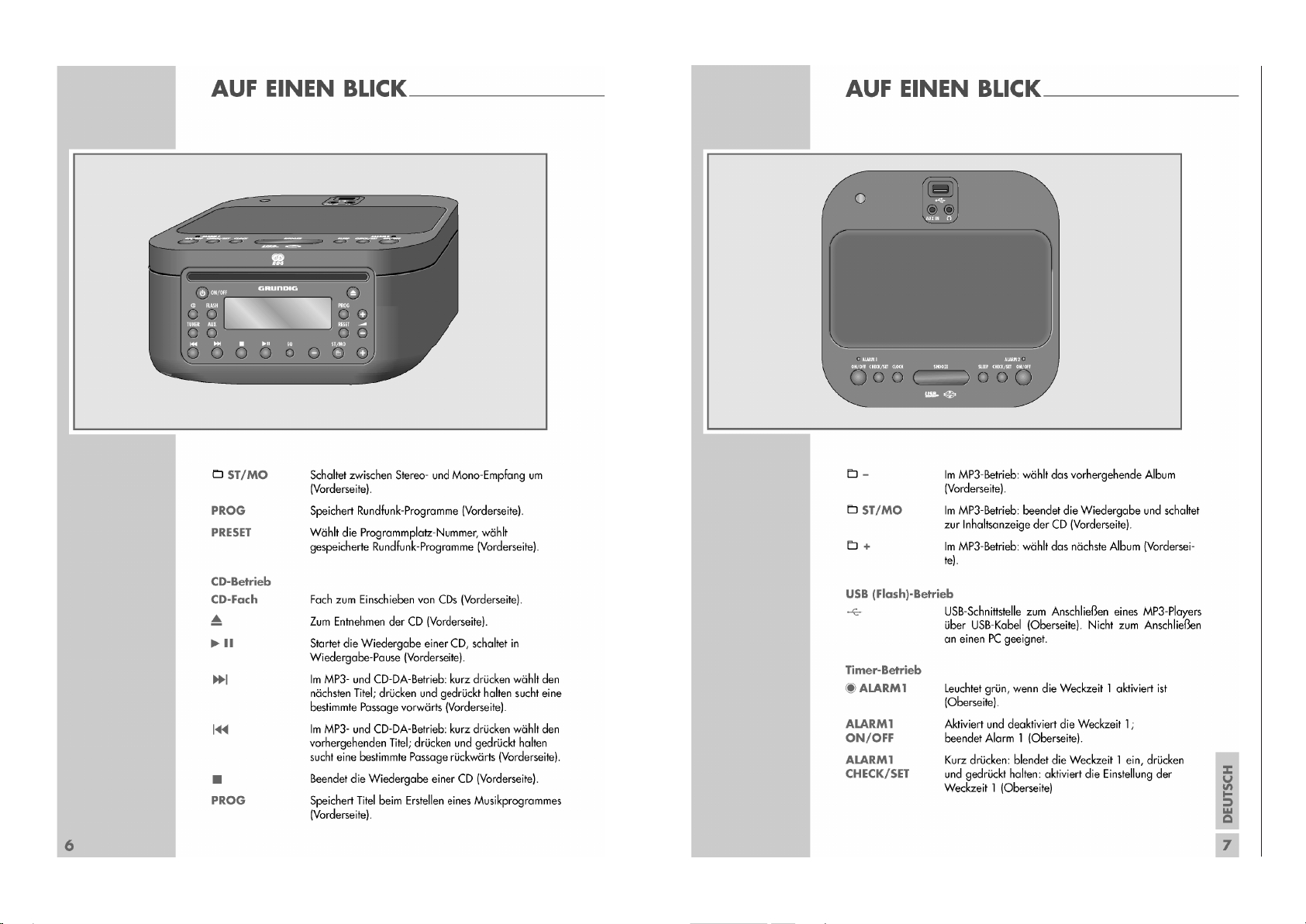
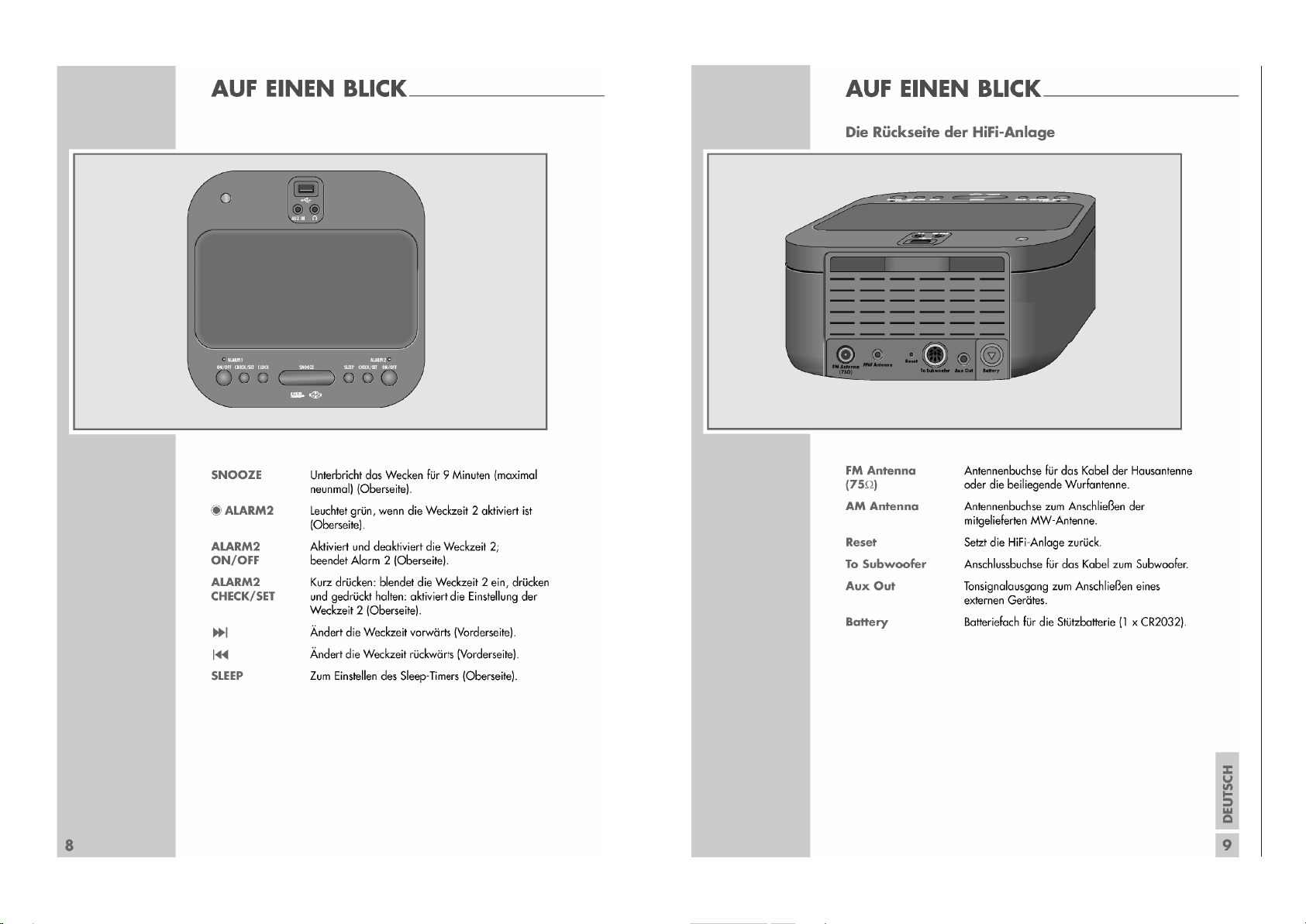
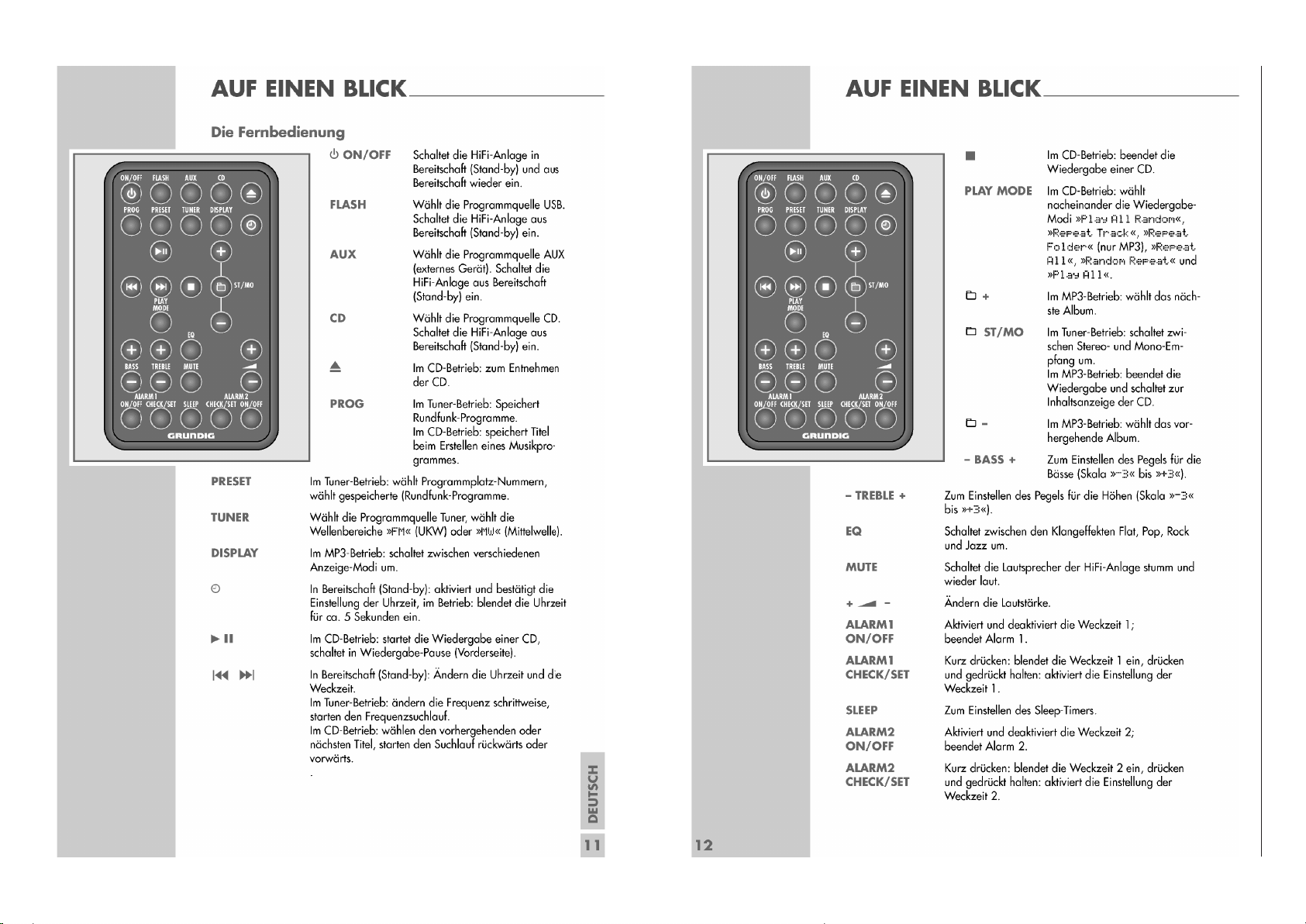
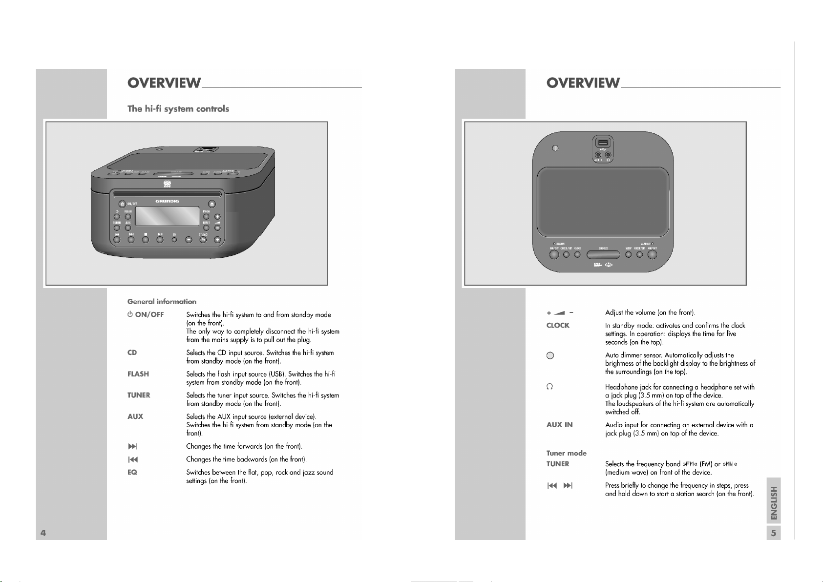
Bedienhinweise
Dieses Kapitel enthält Auszüge aus der Bedienungsanleitung. Weitergehende Informationen entnehmen Sie bitte der gerätespezifischen Bedienungsanleitung, deren Materialnummer Sie in der Ersatzteilliste finden.
1 - 4
GRUNDIG Service CDS 3000 DEC
Page 5
1 - 5
GRUNDIG Service CDS 3000 DEC
Page 6
1 - 6
GRUNDIG Service CDS 3000 DEC
Page 7
1 - 7
GRUNDIG Service CDS 3000 DEC
Page 8
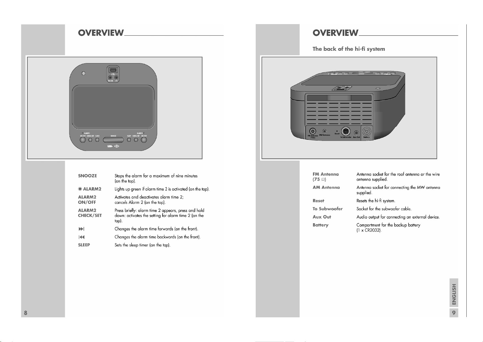
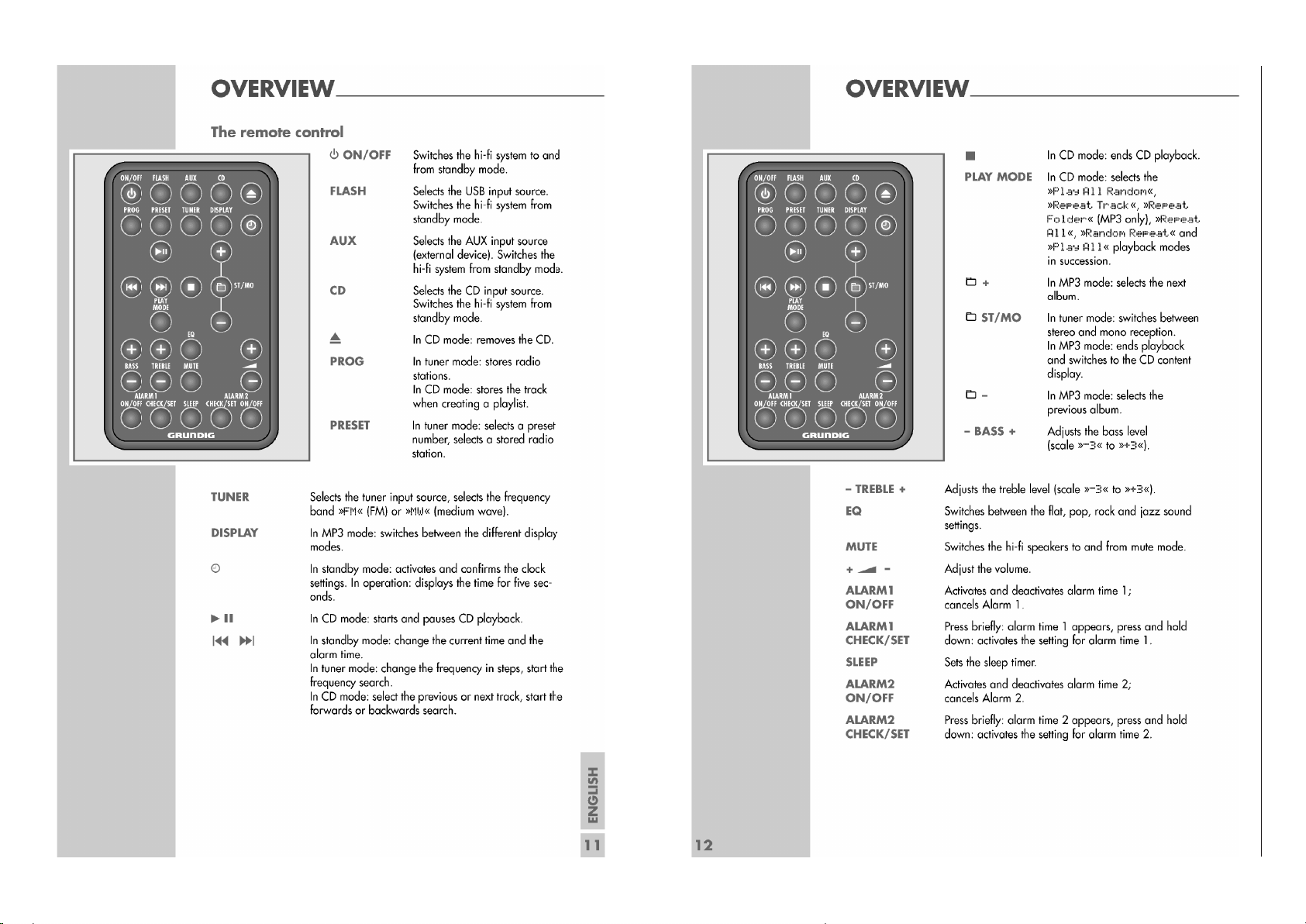
Operating Hints This chapter contains excerpts from the operating instructions.
For further particulars please refer to the appropriate user instructions the part number of which is indicated in the relevant spare parts list.
1 - 8
GRUNDIG Service CDS 3000 DEC
Page 9

1 - 9
GRUNDIG Service CDS 3000 DEC
Page 10
1 - 10
GRUNDIG Service CDS 3000 DEC
Page 11
1 - 11
GRUNDIG Service CDS 3000 DEC
Page 12
GRUNDIG Service CDS 3000 DEC
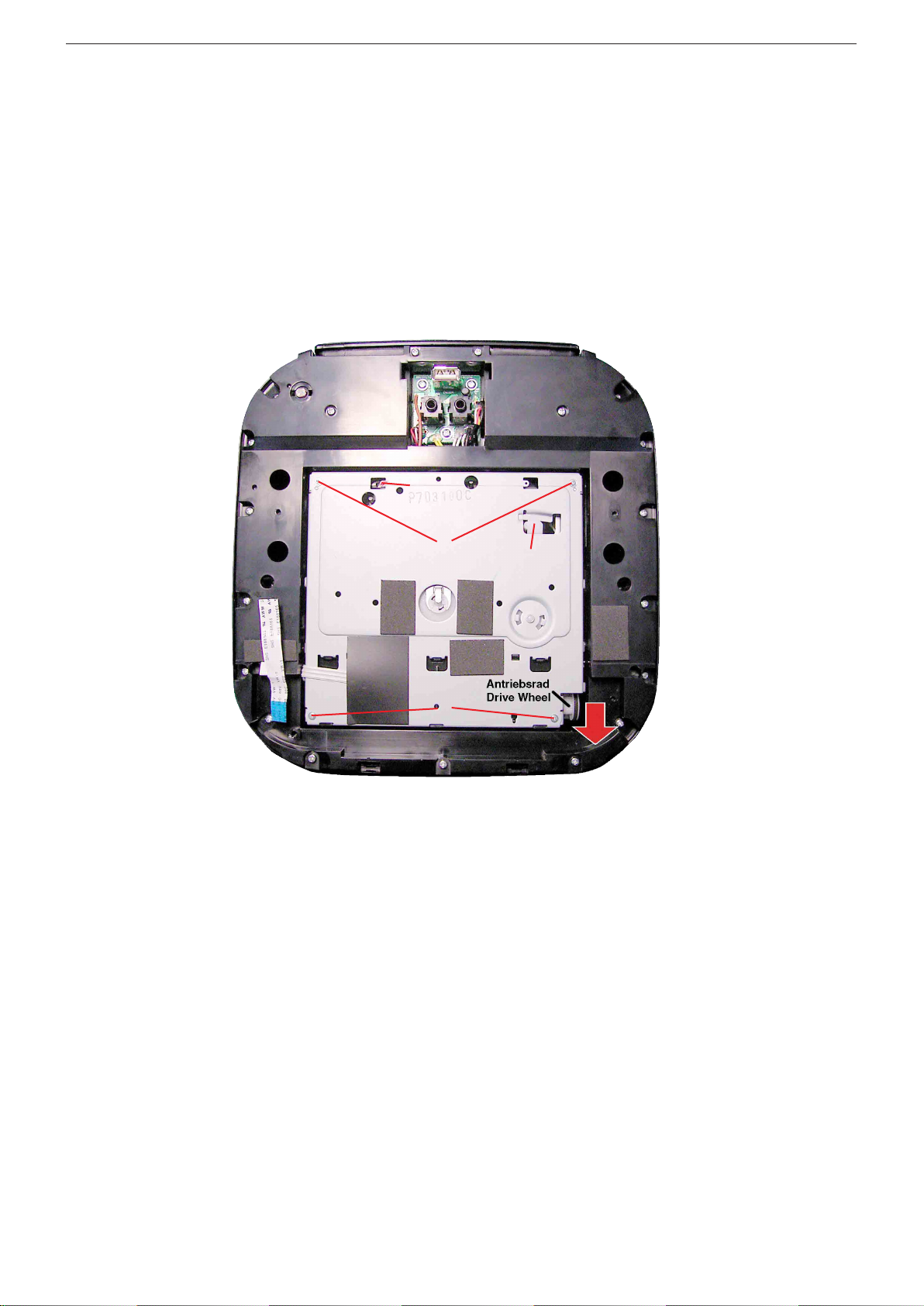
Service Hinweise
CD entnehmen bei defektem Antrieb
Gehäuseoberteil abnehmen (16 Rastnasen A - Seite 1-13).
Achtung: Flexprint!
Antriebsrad in Pfeilrichtung drehen, bis CD ausgeworfen ist.
CD entnehmen bei defekter Mechanik
Gehäuseoberteil abnehmen (16 Rastnasen A - Seite 1-13).
Achtung: Flexprint!
4 Schrauben B herausschrauben.
Achtung: Feder C! Stellung Hebel D beachten!
Service Notes
Removing the CD with defective drive
Remove the top of the cabinet (16 latches A - page 1-13)
Attention: Flexprint!
Turn drive wheel in direction of the arrow until CD is ejected.
Removing the CD with defective mechanism
Remove the top of the cabinet (16 latches A - page 1-13)
Attention: Flexprint!
Undo 4 screws B.
Attention: Spring C! Observe position of lever D!
C
B
B
D
1 - 12
Page 13

F
F
B
B
B
D
D
E
E
E
C
C
C
A
A
A
A
Ausbauhinweise / Disassembly Hints
Gehäuseoberteil / Top of the cabinet:
Rastnasen/latches A
Gehäuseunterteil / Bottom of the cabinet:
B,C,D,E,F
GRUNDIG Service CDS 3000 DEC
1 - 13
Page 14

GRUNDIG Service CDS 3000 DEC
A
C
D
E
F
B
1 - 14
Page 15

Schaltpläne und Platinenabbildungen / Circuit Diagrams and Layout of the PCBs
Blockschaltplan / Block Diagram
2 - 1
GRUNDIG Service CDS 3000 DEC
Page 16

Verdrahtungsplan / Wiring
2 - 2
GRUNDIG Service CDS 3000 DEC
Page 17

GRUNDIG Service CDS 3000 DEC
40V/3A
1
2
3
4
5
6
7
8
9
CN1
DN-105-M5
AF Gnd
Can/Gnd
AF IN
SYS
MUTE
P/GND
-17V
+17V
Q1
9014/C
R1 47K
R4
220
R2 47K
LED1
Green
P1
P2
P3
P4
P5
P6
P7
P8
P9
115'
230V/50Hz
C1209
20n(II)50V
C1211
20n(II)100V
C1212
4700u35V
C1213
4700u35V
C1214
3300u50V
C1201
10n(II)50V
C1202
10n(II)50V
C1203
10n(II)50V
C1210
20n(II)50V
C1204
10n(II)50V
C1207
10n(II)100V
C1208
10n(II)100V
C1206
10n(II)100V
C1205
10n(II)100V
+
1
-
2
~
4
~
3
D1201
KBPC101ST
+
1
-
2
~
4
~
3
D1202
KBPC101ST
T H E R M A L
F U S E
C
T1201
P3B
P2B
P3A
17V~
P2A
17V~
P6BP6A
32V~
P4B
P1A
GND
P1B
GND
P7AP7B
1
2
CN103
+
1
-
2
~
4
~
3
D1203
KBP01
C1216
10n50V
C1215
10n50V
C1217
10n50V
C1218
10n50V
C1219
20n50V
C1220
4700u/16V
1
2
3
4
5
CN101
SEC
SEC
P4A
10V5~
P5AP5B
1
2
3
4
5
6
CN2
1
2
3
4
CN3
P/GND
-17V
-17V
+17V
+17V
14V8
Fuse04
T 1.25A L 250V
14V8
14V8
(9PIN DIN SOCKET)
D1
IN4148
AC 10V5
Fuse01
T 1A25 L 250V
POWER SW.
T105
Fuse Holder FH-B02
P10
R3 100
1
2
3
4
5
CN301
1
2
3
4
5
6
CN301A
1
2
3
4
CN302
1
2
3
4
CN302A
C1222
100n(II)100V
C1221
470n(II)100V
Fuse01
T 3.15A L 250V
Fuse02
T 3.15A L 250V
Netzteil (Bassbox) / Power Supply (Subwoofer)
Netzteilplatte / Rectifier Board
Verbindungsplatte /
Connector Board
POW-Platte / POW Board
2 - 3
POW-LED-Platte /
POW LED Board
Page 18

GRUNDIG Service CDS 3000 DEC
Netzteilplatte (Bassbox) / Rectifier Board (Subwoofer)
Sicht auf Bestückungsseite / View on Component Side
POW-Platte / POW Board
Sicht auf Bestückungsseite / View on Component Side
Sicht auf Lötseite / View on Solder Side
POW-LED-Platte / POW LED Board
Sicht auf Bestückungsseite / View on Component Side
Verbindungsplatte / Connector Board
Sicht auf Bestückungsseite / View on Component Side
Netzschalterplatte / Power Switch Board
Sicht auf Bestückungsseite / View on Component Side
2 - 4
Page 19

Woofer-Verstärkerplatte (Bassbox) / Woofer Amplifier Board (Subwoofer)
R216
4K7
C228
1u
R220
22K
R223
12K
C231
47P
R215
47K
R219
47K
R211
390
R212
390
C232
22u
C219
22u/16V
C220
22u/16V
R224
5K6
R222
10K
C221
6n8
C213
100n
C214
22u
C223
47n
C222
6n8
C218
100n
C216
100u/16V
C217
100n
C215
100u/16V
C209
1u/MT
C210
1u/MT
D203
UDZS10B(9V7)
R203
47K
R204
68
D204
1SS355
D201
UDZS10B(9V7)
R202
68
D202
1SS355
R201
47K
L201
20uH
C203
0.47u/50V(MT)
C211
1u/MT
C212
1u/MT
R207
47K
R208
68
D208
1SS355
R206
68
D206 1SS355
R205
47K
L202
20uH
C205
1u/50V(MT)
C208
0.47u/50V(MT)
D207
UDZS10B(9V7)
D205
UDZS10B(9V7)
R213
47K
C225
330P
R209
1K5
4 Ohm SPK
R214
43K
C202
0.47u/50(MT)
C201
3300u/50V(LESR)
R242
68
5
6
7
4
IC202B
NJM4560(O/AMP)
3
2
1
8
IC202A
NJM4560(O/AMP)
2
1
3
Q203
FR9024
2
1
3
Q202
FR014
2
1
3
Q204
FR014
D211
IN4148
Q207
9014/C
R240
47K
C235
47u
R241
68K
R235
10K
(ZXFN1000)
(ZXFN1000)
2
1
3
Q201
FR9024
R210
180
12V
1
2
3
4
5
6
7
8 9
10
11
12
13
14
15
16
IC201
ZXCD1000
D216
***
C204
1u/50V(MT)
R221
33
R238
47K
Q208
9015/C
R236
47K
C253
1n
2
1
3
VR201
200K(B)
R245
100K
R246
100K
R244
180K
R243
47K
C226
100u/16V
D209
1SS355
D210
1SS355
1
2
CN201
40V/3A
40V
40V
GND
SYS ON
VOVI
G
IC203
78M15
C241
470u/16V
C239
100u/50V
C240
100n/16V
C229
1u
AF GND
AF IN
14.5V
15V
1
2
3
4
CN202
Q211
B772
Q210
9014/C
R233
22K
R231
10K
R232
47K
R237
***
R256
0.5 ohm/5W
R250
68/1W
JP1
SOL PAD
SPK+
PAD
R248
68
R249
68/1W
RLY201
RELAY 1P2T
D213
IN4148
D214
***
SPK-
PAD
D215
***
R239
18K
C238
100u/50V
Q212
***
R234
***
C236
***
R230
4K7
C227
1n
C233
100n
C224
47n
R225
8K2
R226
470
R227
680
Q205
9014/C
Q206
9014/C
R218
100K
R217
27K
R228
56K
C234
47u
R258
47/1W
RLY202
RELAY 1P2T
D212
IN4148
Q209
9014/C
R252
47K
C237
220u
R251
180K
R254
47K
R253
18K
R247
***
D217
IN4148
D218
IN4148
R229
100K
R257
22K
Mute
R255
***
R259
4K7
C242
***
4Tx2
4Tx2
C244
100n
C245
10n
C230
***
***not used
GRUNDIG Service CDS 3000 DEC
2 - 5
Page 20

GRUNDIG Service CDS 3000 DEC
Woofer-Verstärkerplatte (Bassbox) / Woofer Amplifier Board (Subwoofer)
Sicht auf Bestückungsseite / View on Component Side
Sicht auf Lötseite / View on Solder Side
2 - 6
Page 21

Verstärker / Audio Amplifier Board
2 - 7
GRUNDIG Service CDS 3000 DEC
Page 22

GRUNDIG Service CDS 3000 DEC
Verstärker / Audio Amplifier Board
Sicht auf Lötseite / View on Solder SideSicht auf Bestückungsseite / View on Component Side
2 - 8
Page 23

Volume-Platte / Volume Board
2 - 9
GRUNDIG Service CDS 3000 DEC
Page 24

Volume-Platte / Volume Board
2 - 10
GRUNDIG Service CDS 3000 DEC
Sicht auf Bestückungsseite / View on Component Side
Page 25

Volume-Platte / Volume Board
2 - 11
GRUNDIG Service CDS 3000 DEC
Sicht auf Lötseite / View on Solder Side
Page 26

GRUNDIG Service CDS 3000 DEC
FU CLK/3871
MCU_RESET
FU DATA/3871
MAIN POWER
LCD RESET
INH
DECINT
FU/TU CE
KEY1
OPTION IN1
OPTION IN2
RDS_ DATA
DSP SENSE
MD7
MWR/MCK
MD4
MD3
LD M+
MLT
AMP MUTE
KEY2
KEY3
XRST
MRD/MDATA
MD1
MD3
MD2
MD5
OPTION IN1
MCS
MD2
REMOCON
MAIN MUTE
MD4
OPTION IN2
MD6
MD7
MD6
STEREO
SCL
CS
MD5
MD1
RS
RS
SI
SI
SCL
CS
RDS_CLK
TUNER ON
TU CLK FU CLK/3811
TU DATA IN
TU DATA OUT FU DATA/3811
KEY3
KEY2
KEY1
BLIGHT
ALARM2
ALARM2
CD ON
MD0
MD0
ALARM1
ALARM1
MADDR
SENSE
LIMIT SW
M GND
CD R
LD M-
MOTOR 8V
GND
AUDIO-GND
CD ON
CD L
GND
M GND
R329
100
R310
68
R321 10K
R312 10K
+
C305
4.7u10V/S
C311
104
D329
OPEN
+
C303
47u10V/S
C314
104
P5.3
1
P5.4
2
P5.5
3
P5.6
4
P5.7
5
P3.0
6
P3.1
7
P3.2
8
P3.3
9
P3.4
10
P3.5
11
VDD1(INT)
12
VSS1
13
XOUT
14
XIN
15
TEST
16
XTIN
17
XTOUT
18
RESET
19
VREG
20
P0.0
21
P0.1
22
P0.2
23
P0.3
24
P0.425P0.526P0.627P0.728P1.029P1.130P1.231P1.332P1.433P1.534P1.635P2.036P2.137P2.238P2.339P2.4
40
P2.5
41
P2.6
42
P2.7
43
AVREF
44
AVSS
45
VLC0
46
VLC1
47
VLC2
48
VLC3
49
P8.0
50
P8.1
51
P8.2
52
P8.3
53
P8.4
54
P8.5
55
P8.6
56
P8.7
57
P7.0
58
P7.1
59
P7.2
60
P7.3
61
P6.0
62
P6.1
63
P6.2
64
P6.365P6.466P6.567P6.668P6.769P4.171P4.070P4.272P4.373P4.474P4.575P4.676P4.777P5.078P5.179P5.2
80
IC301
S3C828A
R323
1K
Q302
9013H
D327
OPEN
D326
OPEN
R324
22K
D303
IN5817
D330
OPEN
C313
104
C308
OPEN
+
C304
47u10V/S
D323
OPEN
C320
104
D331
OPEN
R331
10K
+
C307
100u10V/S
D322
OPEN
R332
10K
+
C302
100u10V/S
D321
OPEN
D307
OPEN
R316 0
D325
OPEN
D320
OPEN
R320 10K
D332
OPEN
D309
OPEN
D311
OPEN
C312
104
R330
100
D315
OPEN
R306
100
D319
OPEN
R314 0
D312
1N4148
R315 0
2
3
4
5
6
7
8
1
9
10
11
12
13
14
15
CN307
FPC 1.0-15P(LCD&KEY)
R304
100
D304
1N4001
D314
1N4148
C309
104
D317
OPEN
D313
OPEN
R328
100
D318
OPEN
R319 10K
D301
4.7V
D316
OPEN
VCC1GND2OUT
3
IC303
KIA7042P
D328
OPEN
R309
9K1
R313 100
R326
100
R311 12K
D306
1N4001
D302
IN5817
R322
5.6K
R305 0
D324
OPEN
MCU 3.3V
MCU AD 3.3V
MCU AD 3.3V
MCU 3.3V
5V
MCU 3.3V
MCU AD 3.3V
LCD 5V
FU/TU CE
TU DATA IN
STEREO
TAPE SW2
REMOCON
RDS DATA
RDS CLK
TUNER ON
MECHA SW
D310
1N4148
D308
1N4148
D305
WIRE
LCD 5V
FU CLK/3811
FU DATA/3811
BUZZER
R350
0
1
2
CN309
2PINS
BACKUP BATT
R351
10K
FU CLK/3871
FU DATA/3871
LED-BL2
LED-BL1
LED-BL3
LED-BL3
R362
OPEN
R361
OPEN
R364
OPEN
R363
OPEN
R366
OPEN
R365
OPEN
123
CN311
3PINS
R352 100
R353
100
R354
R355
R356
MCU AD 3.3V
R357 10K
LED-BL1
LED-BL2
LED-BL3
R360
OPEN
R358 10K
R359 10K
Q305
OPEN
Q306
OPEN
Q307
OPEN
+C306
47uF
Q304
9014C
J1
SHORT
TU CLK
TU/DATA.IN
TU/DAT.OUT
TU CE
STEREO
TS_RESET
J2
OPEN
1
2
3
4
5
CN308
5PINS
CDS
R368
1M
R371
3K9
R369
10K
R372 10
R370
22K
C321
10n
Q308
9014C
C322
10n
J3
SHORT
AL.CDS
AL.CDS
R374 0
5V
LCD RESET
R379
330
R380
100
C3231n
C324
OPEN
C325
1n
C326
1n
C327
1n
C328
OPEN
1
2
3
4
5
CN701
5PINS
CDS
CDS
KEY1
KEY2
KEY3
REM.IN
LCD5V
AL.DIN
GND
RS
SI
SCL
RESET
CS
BLIGHT
ALARM2
ALARM1
1
2
CN08
2PINS
BT1
DC 3V
C310
100n
C329 1n
C330 1n
C317
100n
+
C301
47u10V/S
D334
1N4001
R381
10K
R382
10K
TS_ RESET
C332 1n
C331
1n
TS_ RESET
TO CN308
CDS-Platte / CDS Board
MCU-Platte / MCU Board
M5V
C334
100n
C333
100n
Q701
9014
L701
45mH
R701
0
R702
1K
R703
220
D335
1N5817
D336
1N5817
1
2
3
4
5
6
7
8
9
10
11
12
13
CN303
13PINS 1.5mm
R307 100
R308
100
RDS DATA
RDS CLK
P1
P2
RDS_ DATA
RDS_CLK
1
2
3
4
5
6
7
8
9
10
11
12
CN302
12PINS 1.5mm
AUDIO-GND
1
2
CN304
2PINS
C337 100n
C338
104
Batterie-Platte / Batt Board
MCU-Teil / MCU Part
2 - 12
Page 27

GRUNDIG Service CDS 3000 DEC
MCU_RESET
INH
MWR/MCK
XRST
OPTION IN1
SCL
MAIN POWER
MLT
51F POWER
51OUT-UIN
MD5
MAIN MUTE
HOST RDY
DSP SENSE
OPTION IN2
MRD/MDATA
AMP MUTE
HOST CLK
MD6
UOUT-51IN
MD7
CS
RS
SI
MD0
MD1
MD2
MD3
MD4
MD7
MD6
MD5
MADDR
MCS
DECINT
SENSE
LIMIT SW
LIMIT SW
nPCMCS
M GND
MECHA SW
CD R
CD L
M 5V
AUDIO-GND
DEMAND
M3.3V
LD M+
MOTOR 8V
LD M-
R333 1K
R327 0
R312 10K
P5.3
1
P5.4
2
P5.5
3
P5.6
4
P5.7
5
P3.0
6
P3.1
7
P3.2
8
P3.3
9
P3.4
10
P3.5
11
VDD1(INT)
12
VSS1
13
XOUT
14
XIN
15
TEST
16
XTIN
17
XTOUT
18
RESET
19
VREG
20
P0.0
21
P0.1
22
P0.2
23
P0.3
24
P0.425P0.526P0.627P0.728P1.029P1.1
P4.5
P4.676P4.777P5.078P5.179P5.2
80
D327
OPEN
D326
OPEN
R343 1K
D330
OPEN
C313
104
R342 1K
D323
OPEN
C320
104
R340 1K
X301
7.93MHz
D325
OPEN
C319
22P
C318
22P
C312
104
R367 0
R338 1K
R337 1K
X302
32.768KHz
R336 1K
R325
100
C315
47P
D328
OPEN
R313 100
R341 1K
C316
40P
R335 1K
R339 1K
R322
5.6K
D324
OPEN
R334 1K
MCU 3.3V
MCU AD 3.3V
REMOCON
RDS DATA
RDS CLK
TUNER ON
MD7
USB_DET
MD4
MD6
USB D+
MD3
nPCMCS
MWR/MCK
MD1
U_DM
MD5
MCS
USB_LED_CON
U_DP
DEMAND
MD0
MD2
TAPE SW2
RM2
1M
CM1
22P
RM58 100
R318
2K2
nRESET
1
DATA0
2
DATA1
3
DATA2
4
DATA3
5
DATA4
6
DATA5
7
DATA6
8
DATA7
9
VDD0
10
VSS0
11
nPCMCS
12
nMWR13DEMAND14DEBUG15DBG_CLK16DBG_CSB17DBG_DAT18SD_DATA019SD_DATA1
20
SD_DATA221SD_DATA322SD_CMD23SD_CLK
24
HOST_INT
36
HOST_RDY
35
HOST_OUT
34
VSS1
33
VDD1
32
HOST_IN
31
HOST_CLK
30
USB_DET
29
SD_DET
28
VSSF
27
VDDF
26
EXHV
25
TEST
48
MS_CLK
47
USB_LED
46
XTALO
45
XTALI
44
UVDD
43
UDM
42
UDP
41
UVSS
40
PLLVSS
39
PLLFILTER
38
PLLVDD
37
IC302
TMC51F01M
CM2
22P
RM41
OPEN
RM59 100
CM6
104
LM2 10UH
R317
22K
CM5 820pF
RM26
100
LM1
10UH
R301
47K
TP
1
TP1
RM28
0.47(1/4,FR)
CM10
104
RM9
22
CM9 104
CM12
104
CM11
104
RM31
15K
RM10
22
RM3
22
RM4
22
+
CM17
47uF/16V
RM11
22
RM27
39
+
CM14
47uF/16V
RM5
22
CM3
103
CM4 104
RM1
4K7
RM6
22
RM29
39
RM7
22
RM56 100
RM12
100
RM42
330
RM8
22
RM30
15K
RM13
22
1
2
3
4
5
CN301
5PINS(TO USB JACK)
XM1
12MHz
RM57 100
M3.3V
MCU AD 3.3V
M5V
M3.3V
51F POWER
M3.3V
M5V
TMC51F01M-01 MAIN
USB BOARD
U/GND
U/DP
U/DM
U/V+
GND
R302
100
MRD/MDATA
R303 100
MADDR
FU DATA/3871
LED-BL2
LED-BL1
R353
100
R354
1K
R355
1K
R356
1K
27
28
29
30
31
32
1
2
3
4
5
6
7
8
9
10
11
12
13
14
15
16
17
18
19
20
21
22
23
24
25
26
CN306
32PINS(16X2)
Q303
9014C
M3.3V
51OUT-UIN
HOST RDY
HOST CLK
UOUT-51IN
DECINT
MCS
MWR/MCK
MRD/MDATA
MADDR
MD0
MD1
MD2
MD3
MD4
MD5
MD7
DSP SENSE
XRST
MLT
SENSE
LIMIT SW
nPCMCS
DEMAND
MECHA SW
LD M+
LD MM GND
M 8V
M 5V
A GND
CD-L
CD-R
M3.3V
MAD3.3V
CD ON
MD6
R375
470
R376
1K
R377
470
R378
470
CM8
10P
CM7
10P
TS_ RESET
TO SERVO PCB
C335
*
C336
*
*not used
J4
SHORT PAD
CD ON
C334
100n
C333
100n
RM32
0
CM13
104
CM18
104
M3.3V
MCU-Teil / MCU Part
2 - 13
Page 28

GRUNDIG Service CDS 3000 DEC
MCU-Teil / MCU Part
Sicht auf Bestückungsseite / View on Component Side
MCU-Platte / MCU Board
CDS-Platte / CDS Board Batterie-Platte / BATT Board
2 - 14
Page 29

GRUNDIG Service CDS 3000 DEC
MCU-Teil / MCU Part
Sicht auf Lötseite / View on Solder Side
MCU-Platte / MCU Board
CDS-Platte / CDS Board Batterie-Platte / BATT Board
2 - 15
Page 30

GRUNDIG Service CDS 3000 DEC
CD-Servo-Platte / CD Servo Board
2 - 16
Page 31

GRUNDIG Service CDS 3000 DEC
CD-Servo-Platte / CD Servo Board
2 - 17
Page 32

GRUNDIG Service CDS 3000 DEC
CD-Servo-Platte / CD Servo Board
Sicht auf Bestückungsseite / View on Component Side
Sicht auf Lötseite / View on Solder Side
2 - 18
Page 33

Displayplatte / Display Board
7002-
r
pA-3
2
C132
100n
C134
100n
C135
100n
C136
100n
C133
100n
R180
91K
RS
1
DB7(SI)
2
XRESET
3
DB6(SCL)
4
DB5(/CS)
5
DB4
6
DB3
7
DB2
8
DB1
9
DB0
10
PSB
11
RW
12
E
13
COM[9]14COM[10]15COM[11]16COM[12]17COM[13]18COM[14]19COM[15]20COM[16]21SEG[41]22SEG[42]23SEG[43]24SEG[44]25SEG[45]26SEG[46]27SEG[47]28SEG[48]29SEG[49]30SEG[50]31SEG[51]32SEG[52]33SEG[53]34SEG[54]35SEG[55]36SEG[56]37SEG[57]38SEG[58]39SEG[59]40SEG[60]41SEG[61]42SEG[62]43SEG[63]44SEG[64]45SEG[65]46SEG[66]47SEG[67]48SEG[68]49SEG[69]50SEG[70]51SEG[71]52SEG[72]53SEG[73]54SEG[74]55SEG[75]56SEG[76]57SEG[77]58SEG[78]59SEG[79]60SEG[80]
61
D
62
M
63
CL2
64
CL1
65
OSC2
66
OSC1
67
VSS
68
V4
69
V3
70
V2
71
V1
72
V0
73
VCC
74
SEG[40]75SEG[39]76SEG[38]77SEG[37]78SEG[36]79SEG[35]80SEG[34]81SEG[33]82SEG[32]83SEG[31]84SEG[30]85SEG[29]86SEG[28]87SEG[27]88SEG[26]89SEG[25]90SEG[24]91SEG[23]92SEG[22]93SEG[21]94SEG[20]95SEG[19]96SEG[18]97SEG[17]98SEG[16]99SEG[15]
100
SEG[14]
101
SEG[13]
102
SEG[12]
103
SEG[11]
104
SEG[10]
105
SEG[9]
106
SEG[8]
107
SEG[7]
108
SEG[6]
109
SEG[5]
110
SEG[4]
111
SEG[3]
112
SEG[2]
113
SEG[1]
114
COM[1]
115
COM[2]
116
COM[3]
117
COM[4]
118
COM[5]
119
COM[6]
120
COM[7]
121
COM[8]
122
IC101
ST7070
BEDSIDE-LCD-DISPLAY
COM(8)1COM(7)2COM(6)3COM(5)4COM(4)5COM(3)6COM(2)7COM(1)8SEG19SEG210SEG311SEG412SEG513SEG614SEG715SEG816SEG917SEG1018SEG1119SEG1220SEG1321SEG1422SEG1523SEG1624SEG1725SEG1826SEG1927SEG2028SEG2129SEG2230SEG2331SEG2432SEG2533SEG2634SEG2735SEG2836SEG2937SEG3038SEG3139SEG3240SEG3341SEG3442SEG3543SEG3644SEG3745SEG3846SEG3947SEG4048SEG8049SEG7950SEG7851SEG7752SEG7653SEG7554SEG7455SEG7356SEG7257SEG7158SEG7059SEG6960SEG6861SEG6762SEG6663SEG6564SEG6465SEG6366SEG6267SEG6168SEG6069SEG5970SEG5871SEG5772SEG5673SEG5574SEG5475SEG5376SEG5277SEG5178SEG5079SEG4980SEG4881SEG4782SEG4683SEG4584SEG4485SEG4386SEG4287SEG4188COM(16)89COM(15)90COM(14)91COM(13)92COM(12)93COM(11)94COM(10)95COM(9)
96
DISPLAY
R182
6K8
R181
560
C131
100n
P1
SHORT
P2
OPEN
LED1
BACK LIGHT
R183
0
+5V
+5V
+5V
GND
RS
SI
/RES
SCL
CS
P1
P2
1
2
3
4
5
6
7
8
9
10
11
12
13
14
15
CN1
Alarm LEDDimmer
BACKLIGHT
KEY3
KEY1
KEY2
REMOCON
S1
Power
S2
CD
S6
AUX
S3
Vol.up
S4
Vol.dwon
S7
Flash
S10
Eject
S8
EQ
S15
Skip down
S16
Stop
S14
Skip up
S13
Play/Pause
S17
Home Down
S18
Home
R1
OP
R4
910R51K1R61K3
R7
1K8
R9
3K
R8
2K
R12
10K
R11
6K2
R10
3K9
R2
OP
R15
910
R16
1K1
R17
1K3
R18
1K8
R192KR20
3K
R21
3K9
S19
Home up
S20
Program
R3
OP
R26
910
S25
Tuner/Band
S26
Preset
1
2
3
4
5
6
7
8
CN2
C111
47u
KEY3
KEY2
KEY1
GND
Alarm 1
Alarm 2
Stereo/Mono
5V
1
2
3
CN3
REMOCON
Bedside Dis & key Module
WHITE
*
*
FOR ADJ
Alarm LED Dimmer
RMC OUT
1
GND
2
VCC
3
IR01
IR
1
2
3
CN01
3PINS
2 - 19
GRUNDIG Service CDS 3000 DEC
Page 34

GRUNDIG Service CDS 3000 DEC
Sicht auf Bestückungsseite / View on Component Side
Displayplatte / Display Board
Sicht auf Lötseite / View on Solder Side
Displayplatte / Display Board
IR-Platte / IR Board
IR-Platte / IR Board
2 - 20
Page 35

GRUNDIG Service CDS 3000 DEC
7002-rp
A-
3
2
S9
Clock
R106
10K 1%
S21
Snooze
S22
Sleep
R102
2K4 1%
R103
1K8 1%
R104
2K 1%
S28
Alarm 1
set
S29
Alarm 1
on/off
S30
Alarm 2
set
S31
Alarm 2
on/off
R105
3K 1%
R101
6K2 1%
Q112
9014C
R114
4K7
1
2
3
4
5
6
7
8
CN2B
R113
100
LED102
Alarm 2
LED101
Alarm 1
C101
10n
5V
Alarm 2
Alarm 1
GND
K2
K1
K3
Q113
9014C
R116
22K
R115
OPEN
C102
10n
Q111
9014C
R112
4K7
R111
100
Q114
9014C
R118
22K
R117
OPEN
C10310n
CDS3000 (KEY BOARD)
R119
4K7
R120
4K7
AL.CDS
P1A
PAD
1
2
3
4
5
CN1003
5PINS
1
2
3
4
5
6
7
CN1002
7PINS
J1001
MSJ-2200D-AG
G
L
R
S1
S1
R
G
L
U/V+
5V
GND
U/DM
U/DP
U/GND
AUX IN
EARPHONE
PHONE BOARD
UGD+D-
U+
USB-BUA713
USB SOCKET
D1002
1N4148
D1001
1N4148
C1001
open
PAD
PAD
L1001
LF-2089
C1002
100n
1
2
3
4
CN1001
4PINS
C1004
10P
C1003
10P
C1005
10P
C1006
10n
J1002
MSJ-2200A-W-AG
4
5
6
SW1001B
J2P2T
1
2
3
SW1001A
J2P2T
S2
S2
C
100n
Bedienteil / Control Section
Bedienplatte / Keyboard
USB-Platte / USB Board
Bedienplatte / Keyboard
Bedienplatte / Keyboard
Sicht auf Bestückungsseite / View on Component Side
Sicht auf Lötseite / View on Solder Side
2 - 21
USB-Platte / USB Board USB-Platte / USB Board
Sicht auf Bestückungsseite / View on Component Side Sicht auf Lötseite / View on Solder Side
Page 36

GRUNDIG Service CDS 3000 DEC
Surround
131415161718192021222324
121110
987654321
T re b l e1
f c = 8 k H z
T r e b le 2
f c = 8 k H z
Ba ss
2
f
0
=80 Hz
Ba ss1
f
0
=80 Hz
Logic
Vcc/2
Vcc/2Vcc/2
Vcc/2
Vcc/2
BD3871FS
0dB
~
–87dB
–•
50k50 k
50k
50k50k
50k
24 23 22 21 20 19
BUFF
ALC
AGC
AM
IF
AM
DET
AM
MIX
LA1833N
AM
RF. AMP
AM
OSC
S-CURVE
FM
DET
FM
IF
LEVEL
DET
TUNING
DRIVE
COMP
AM / FM
IF
BUFF
GNDREG
STEREO
SW
FF
38k
VCO
304kHz
P-DET
Ø
PILOT
DET
FF
19k
∠0
FF
19k
∠
2
π
PILOT
CANCEL
DECODER
ANTI-BIRDIE
V
CC
2 3 4 5 6 7 8 10
11 12
18 17
16
15 14
13
91
Oscillator & Ramp
Generator
Internal 5V5
Internal 9V
PWM
Comp A
PWM
Comp B
PreDriver
PreDriver
O/P
Driver
O/P
Driver
Audio A
ZXCD1000
Audio B
V
CC
Cosc
Out A
Out B
5V5
9VB
9VA
Triangle B
Triangle A
Osc B
Osc A
Dist
Gnd
Gnd2
1
234 5 6 7
8
9
10
1112
13
14
15
16
Osc
Buffers
IC Innenschaltpläne / IC Block Diagrams
2 - 22
Page 37

GRUNDIG Service CDS 3000 DEC
5828F/5828C/9828F/9828C/B828F/B828C3S
nRESET
X
IN
XT
IN
Port I/O and Interrupt
Control
SAM88RC
CPU
64/32/16-
Kbyte
ROM
2,614/1,078/
566-byte
Register File
X
OUT
XT
OUT
V
REG
Battery Level
Detector
Watch Timer
LCD Driver/
Controller
V
BLDREF
/P2.7/AD7
BUZ/P1.3
COM0-COM1/P8.0-P8.1
COM2-COM7/SEG0-SEG5/P8.2-P8.7
SEG6-SEG9/P7.0-P7.3
SEG10-SEG17/P6.0-P6.7
SEG18-SEG25/P4.0-P4.7
SEG26-SEG33/P5.0-P5.7
SEG34-SEG37/P3.0-P3.3
VLC0-VLC3
8-Bit Timer/
Counter A
TAOUT/TAPWM/P3.1
TACLK/P3.2
TACAP/P3.3
TBPWM/P3.0
P2.0-P2.6/AD0-AD6
P2.7/AD7/V
BLDREF
P4.0-P4.7/
SEG18-SEG25
8-Bit Timer/
Counter B
16-Bit Timer/
Counter 0
16-Bit Timer/
Counter 1
I/O Port 0
I/O Port 1
I/O Port 2
I/O Port 3
I/O Port 4
I/O Port 5
T1CAP/P1.0
T1CLK/P1.1
T1OUT/T1PWM/P1.2
P0.0-P0.7/
INT0-INT7
P1.0/T1CAP
P1.1/T1CLK
P1.2/T1OUT/T1PWM
P1.3/BUZ
P1.4/SO
P1.5/SCK
P1.6/SI
P3.0/TBPWM/SEG34
P3.1/TAOUT/TAPWM/SEG35
P3.2/TACLK/SEG36
P3.3/TACAP/SEG37
P3.4/TxD
P3.5/RxD
P5.0-P5.7/
SEG26-SEG33
SIO
UART
10-bit ADC
I/O Port 8
I/O Port 7
I/O Port 6
Watchdog
Timer
Basic Timer
SO/P1.4
SCK/P1.5
SI/P1.6
TxD/P3.4
RxD/P3.5
AD0-AD6/P2.0-P2.6
AD7/P2.7/V
BLDREF
P8.0-P8.1/COM0-COM1
P8.2-P8.7/COM2-COM7/SEG0-SEG5
P7.0-P7.3/SEG8-SEG9
P6.0-P6.7/SEG10-SEG17
P0.4/INT4
P0.5/INT5
P0.6/INT6
P0.7/INT7
P1.0/T1CAP
P1.1/T1CLK
P1.2/T1OUT/T1PWM
P1.3/BUZ
P1.4/SO
P1.5/SCK
P1.6/SI
P2.0/AD0
P2.1/AD1
P2.2/AD2
P2.3/AD3
P2.4/AD4
SEG28/P5.2
SEG27/P5.1
SEG26/P5.0
SEG25/P4.7
SEG24/P4.6
SEG23/P4.5
SEG22/P4.4
SEG21/P4.3
SEG20/P4.2
SEG19/P4.1
SEG18/P4.0
SEG17/P6.7
SEG16/P6.6
SEG15/P6.5
SEG14/P6.4
SEG13/P6.3
SEG29/P5.3
SEG30/P5.4
SEG31/P5.5
SEG32/P5.6
SEG33/P5.7
SEG34/P3.0/TBPWM
SEG35/P3.1/TAOUT/TAPWM
SEG36/P3.2/TACLK
SEG37/P3.3/TACAP
P3.4/TxD
P3.5/RxD
VDD
VSS
XOUT
XIN
TEST
XTIN
XTOUT
nRESET
V
REG
P0.0/INT0
P0.1/INT1
P0.2/INT2
P0.3/INT3
S3C828B/F828B
S3C8289/F8289
S3C8285/F8285
(80-QFP-1420C)
64
63
62
61
60
59
58
57
56
55
54
53
52
51
50
49
48
47
46
45
44
43
42
41
1
2
3
4
5
6
7
8
9
10
11
12
13
14
15
16
17
18
19
20
21
22
23
24
80
797877
767574
7372717069
686766
65
252627
2829303132
3334353637
383940
SEG12/P6.2
SEG11/P6.1
SEG10/P6.0
SEG9/P7.3
SEG8/P7.2
SEG7/P7.1
SEG6/P7.0
COM7/SEG5/P8.7
COM6/SEG4/P8.6
COM5/SEG3/P8.5
COM4/SEG2/P8.4
COM3/SEG1/P8.3
COM2/SEG0/P8.2
COM1/P8.1
COM0/P8.0
V
LC3
VLC2
VLC1
VLC0
AVSS
AVREF
P2.7/AD7/VBLDREF
P2.6/AD6
P2.5/AD5
2 - 23
Page 38

3 - 1
GRUNDIG Service CDS 3000 DEC
Explosionszeichnungen und Ersatzteilliste
Exploded Views and Spare Parts List
1
Page 39

3 - 2
GRUNDIG Service CDS 3000 DEC
2
Page 40

Ersatzteilliste
Spare Parts List
7 / 2007
NUR FÜR INTERNEN GEBRAUCH
FOR INTERNAL USE ONLY
ǵ
AUDIO
CDS 3000 DEC
POS. NR. MATERIAL-NR. BEZEICHNUNG
POS. NO. PART NUMBER DESCRIPTION
FS 01 S 759550661900 SICHERUNG T3.15AL/250V
FS 02 S 759550661900 SICHERUNG T3.15AL/250V
S 759540380100 SICHERUNG T1.25AL/250V
FS 04
FS 05
S 759540380100 SICHERUNG T1.25AL/250V
POS. NR. MATERIAL-NR. BEZEICHNUNG
POS. NO. PART NUMBER DESCRIPTION
GRUNDIG Service CDS 3000 DEC
3 - 3
POS. NR. ABB. MATERIAL-NR. ANZ. BEZEICHNUNG DESCRIPTION
POS. NO. FIG. PART NUMBER QTY.
GLR3100 CDS 3000 DEC CDS 3000 DEC
0001.000 1 759550662300 FRONT BLENDE SCHWARZ FRONT PANEL BLACK
0002.000 1 759550662600 BEDIENKNOEPFE LINKS CONTROL KNOBS LEFT
0003.000 1 759550662700 BEDIENKNOEPFE RECHTS CONTROL KNOBS RIGHT
0004.000 S1 759550662200 DISPLAY LINSE DISPLAY LENS
0005.000 1 759550658800 LP-DISPLAY MODULE DISPLAYBOARD
0006.000 S1 759550663600 BEDIENMEMBRANE FRONT KEY MEMBRANE
0007.000 1 759550664500 LP-IR-MODUL KPL. IR BOARD ASSY
0011.000 1 759550659100 HOCHTONLAUTSPRECHER 4 OHM 3.5 TWEETER 4 OHM 3.5 W
0012.000 1 759550659000 LAUTSPRECHER 4 OHM 34MM SPEAKER 4 OHM 34MM
0013.000 1 759550664600 LP-BEDIENMODUL OBEN TOP KEY ASSY
0016.000 1 759550662500 BEDIENKNOEPFE OBEN CONTROL KNOBS TOP
0017.000 1 759550659300 ABDECKUNG GEH.-OBERTEIL TOP COVER
0023.000 1 759550664300 USB BUCHSENPLATTE KPL. USB JACK BOARD ASSY
0024.000 1 759550662000 GEH.-OBERTEIL SCHWARZ TOP CABINET BLACK
0025.000 1 759550664700 LP-DIMMER SENSOR MODUL KPL. DIMMER SENSOR BOARD ASSY
0028.000 1 759550659400 BUZZER BUZZER
0029.000 S1 759550659200 CD-LAUFWERK CD-MECHANISM
0030.000 1 759550668500 CD PLATTE KPL. CD BOARD ASSY
0032.000 1 759550662100 GEHAEUSE M.STOFF UND IR FENSTER CABINET WITH CLOTH AND IR LENS
0034.000 1 759550664200 MCU PLATTE KPL. MCU BOARD ASSY
0037.000 1 759550662400 BODENPLATTE SCHWARZ BOTTOMPLATE BLACK
0044.000 S1 759550663900 VERSTAERKERPLATTE KPL. AMPLIFIER BOARD ASSY
0048.000 1 759550662800 BATTERIEFACHDECKEL SCHWARZ BACKUP BATTERY DOOR BLACK BACK UP
0049.000 1 759550663700 RUECKWAND SCHWARZ BACK COVER BLACK
0078.000 1 759550664000 TUNER KPL. TUNER ASSY
0001.000 2 759550659700 BASSLAUTSPRECHER SUBWOOFER
0003.000 2 759550663500 LAUTSPRECHERGITTER SCHWARZ MIT SPEAKER GRILLE WITH 8 CLIPS
0006.000 2 759550663200 ABDECKUNG BLENDE RECHTS LAUTSP. COVER PANEL RIGHT SUBWOOFERBOX
0009.000 2 759550663100 ABDECKUNG BLENDE LINKS LAUTSPR COVER PANEL LEFT SUBWOOFERBOX
0015.000 2 759550663000 BLENDE RECHTS LAUTSPRECHERBOX PANEL RIGHT SPEAKERBOX
0016.000 2 759550659600 DIN MODUL BSCD-SWF-1-06-00 DIN BOARD BSCD-SWF-1-06-00
0018.000 2 759550659800 GEHAEUSE LAUTSPRECHERBOX CABINET SUBWOOFERBOX
0020.000 S2 759550661800 NETZSCHALTER SCHWARZ RL3-512-G POWER SWITCH BLACK RL3-512-G1-
0021.000 2 759550662900 BLENDE LINKS BASSLAUTPSRECHERB PANEL LEFT SUBWOOFER BOX
0022.000 2 759550661700 ZUGENTLASTUNG SCHWARZ STRAIN RELIEF
0025.000 S2 759550659900 TRAFO RN-65D 230V/60HZ TRAFO RN-65D 230V/60HZ
0023.000 S2 759550659500 NETZTEILMODUL SWF-1-02/04-00 POWERBOARD SWF-1-02/04-00
0029.000 2 759550670500 BASSVERSTAERKERMODUL SUBWOOFER AMPLIFIER BOARD
0100.000 759550663400 VERBINDUNGSKABEL SW GERAET-LAU CONNECTING CABLE BLACK UNIT-SP
0200.000 S 759550661600 NETZKABEL SCHWARZ POWER CORD BLACK
0300.000 720117140400 FERNBEDIENUNG REMOTE CONTROL
0309.000 759550663300 BATTERIEFACHDECKEL SCHW. FERNBED. BATTERIE DOOR BLACK REMOTE CONTR.
720107742500 SERVICE MANUAL D, GB SERVICE MANUAL D, GB
720108000001 SICHERHEITSMANUAL D/GB/E/F/I SAFETY SERVICE MANUAL D/GB/E/F/I
d©
KEIN E-TEIL NO SPARE PART
SUBWOOFER SUBWOOFER
DIE BEDIENUNGSANLEITUNG KOENNEN THE INSTRUCTION MANUAL CAN BE
SIE IM INTERNET UNTER FOLGENDER DOWNLOADED FROM THE INTERNET
ADRESSE ABRUFEN: WWW.GRUNDIG.DE UNDER THE FOLLOWING ADDRESS:
MENU: DOWNLOADS WWW.GRUNDIG.DE MENU: DOWNLOADS
ÄNDERUNGEN VORBEHALTEN / SUBJECT TO ALTERATION
BESTELL-NR. / ORDER NO.: GLR3100
Es gelten die Vorschriften und Sicherheitshinweise
gemäß dem Service Manual "Sicherheit", Mat.-Nummer 720108000001, sowie zusätzlich die eventuell abweichenden, landesspezifischen Vorschriften!
The regulations and safety instructions shall be valid
!
as provided by the "Safety" Service Manual, part
number 720108000001, as well as the respective
( ! )
national deviations.
ÄNDERUNGEN VORBEHALTEN / SUBJECT TO ALTERATION
 Loading...