

Page 1
Audio Service Manual
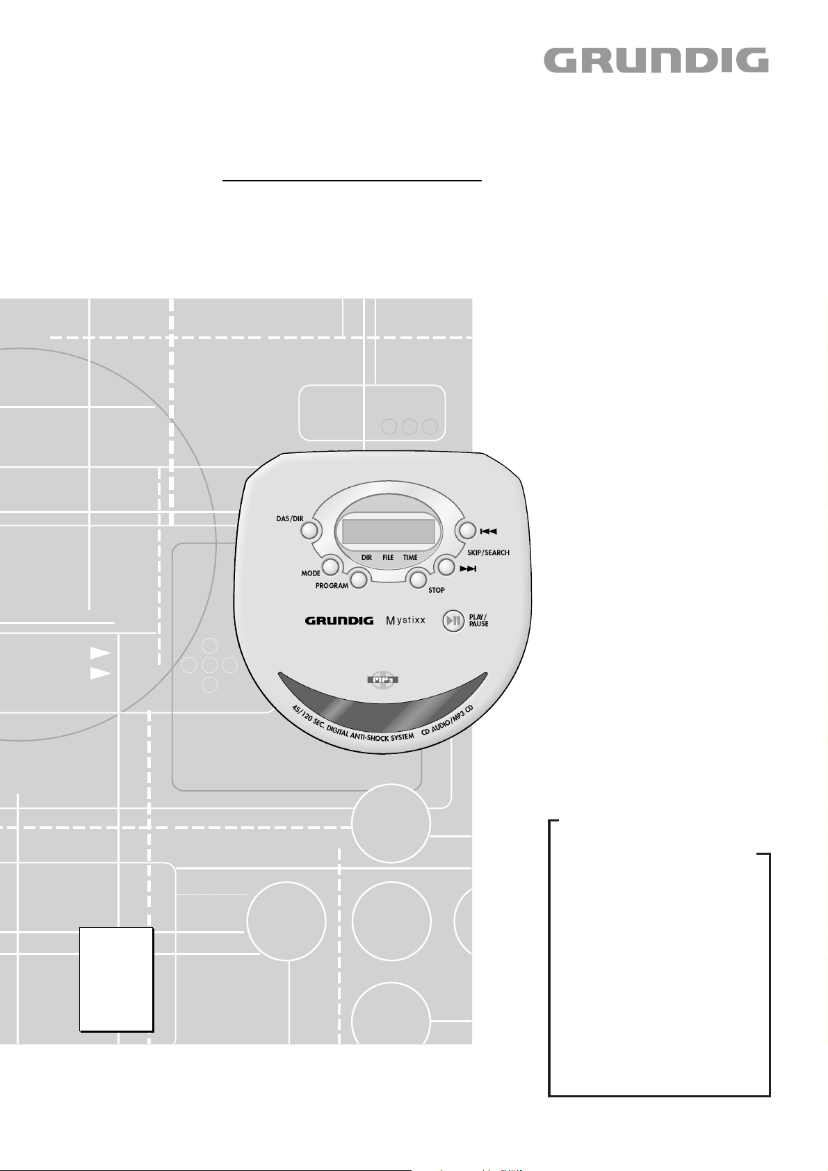
MYSTIXX
CDP 9200 SPCD
GDN9550
Zusätzlich erforderliche Unterlagen für den Komplettservice
Additionally required Service Documents for the Complete Service
Service
Manual
Sicherheit
Safety
Materialnr./Part No.
720108000000
Materialnummer/Part Number 720107723000
Änderungen vorbehalten/Subject to alteration • Printed in Germany • WÜ
H-S43 • 0802 • 8002/8012, 8003/8013, 8005/8015
http://www.grundig.com
Grundig Service
Hotline Deutschland…
Technik:
TV
TV
SAT
VCR/LiveCam
HiFi/Audio
Car Audio
Telekommunikation
Planatron
Ersatzteil-Verkauf: Mo.-Fr. 8.00-19.00 Uhr
Kundendienst/Werkstätten:
gebührenpflichtig
(8.00-22.00 Uhr)
…Mo.-Fr. 8.00-18.00 Uhr
0180/52318-41
0180/52318-49
0180/52318-48
0180/52318-42
0180/52318-43
0180/52318-44
0180/52318-45
Fax:
Telefon: 0180/52318-40
Telefon:
Fax:
0180/52318-51
0180/52318-99
0180/52318-50Fax:
Mo.-Fr. 8.00-18.00 Uhr
0180/52318-52
0180/52318-46
Page 2

Allgemeiner Teil / General Section MYSTIXX CDP 9200 SPCD
Es gelten die Vorschriften und Sicherheitshinweise gemäß dem Service Manual "Sicherheit",
Materialnummer 720108000000, sowie zusätzlich die eventuell abweichenden, landesspezifischen Vorschriften!
Inhaltsverzeichnis
Seite
Allgemeiner Teil ............................. 1 - 2 … 1 - 6
Technische Daten ...................................................................... 1 - 2
Servicehinweise ......................................................................... 1 - 3
Ausbauhinweise ......................................................................... 1 - 4
Bedienhinweise .......................................................................... 1 - 5
Platinenabbildungen
und Schaltpläne ........................... 2 - 1 … 2 - 10
Schaltplan .................................................................................. 2 - 1
Blockschaltplan .......................................................................... 2 - 8
Platinenabbildungen
Display- und Bedien-Platte ..................................................... 2 - 8
Haupt-Platte ........................................................................... 2 - 9
Explosionszeichnung und
Ersatzteilliste .................................. 3 - 1 … 3 - 2
The regulations and safety instructions shall be
valid as provided by the "Safety" Service Manual,
part number 720108000000, as well as the respective national deviations!
Table of Contents
Page
General Section .............................. 1 - 2 … 1 - 8
Technical Data ........................................................................... 1 - 2
Service Hints .............................................................................. 1 - 3
Disassembly Instructions ........................................................... 1 - 4
Operating Hints .......................................................................... 1 - 7
Layout of PCBs
and Circuit Diagrams ................... 2 - 1 … 2 - 10
Circuit Diagram .......................................................................... 2 - 1
Block Diagram ............................................................................ 2 - 8
Layout of the PCBs
Display and Operating Board ................................................. 2 - 8
Main Board ............................................................................. 2 - 9
Exploded View and
Spare Parts List .............................. 3 - 1 … 3 - 2
Allgemeiner Teil
Technische Daten
Spannungsversorgung
AC Netzadapter: ......................... DC 4,5V ј, 500mA Ó extern
Batteriebetrieb: ........................................... 2 x 1,5V (LR6, AM3, AA)
Maximale Leistungsaufnahme bei Netzbetrieb (Akkuladung) .... <2W
Ausgangsleistung
Ohrhörer: ............................................................................. 2 x 5mW
Line Out: .........................................................................0,7V ± 0,1V
CD Spieler
Frequenzgang: ...........................................................20Hz ... 20kHz
Geräuschspannungsabstand: ................................................ ≥ 85dB
Abmessungen und Gewicht
B x H x T .............................................................. 127 x 30 x 134mm
Gewicht (ohne Batterien) ..................................................... ca. 210g
General Section
Technical Data
Power supply
AC mains adapter: ...................... DC 4.5V ј, 500mA Ó extern
Battery operation:....................................... 2 x 1.5V (LR6, AM3, AA)
Max. Power Consumption at mains operation (accu charging) ... <2W
Output
Earphones: .......................................................................... 2 x 5mW
Line Out: .........................................................................0.7V ± 0.1V
CD player
Frequency response: ................................................. 20Hz ... 20kHz
Noise voltage ratio: ............................................................... ≥ 85dB
Dimensions and weight
W x H x D ............................................................. 127 x 30 x 134mm
Weight (without batteries) ............................................ approx. 210g
1 - 2 GRUNDIG Service
Page 3
MYSTIXX CDP 9200 SPCD Allgemeiner Teil / General Section
Servicehinweise
CD-Teil
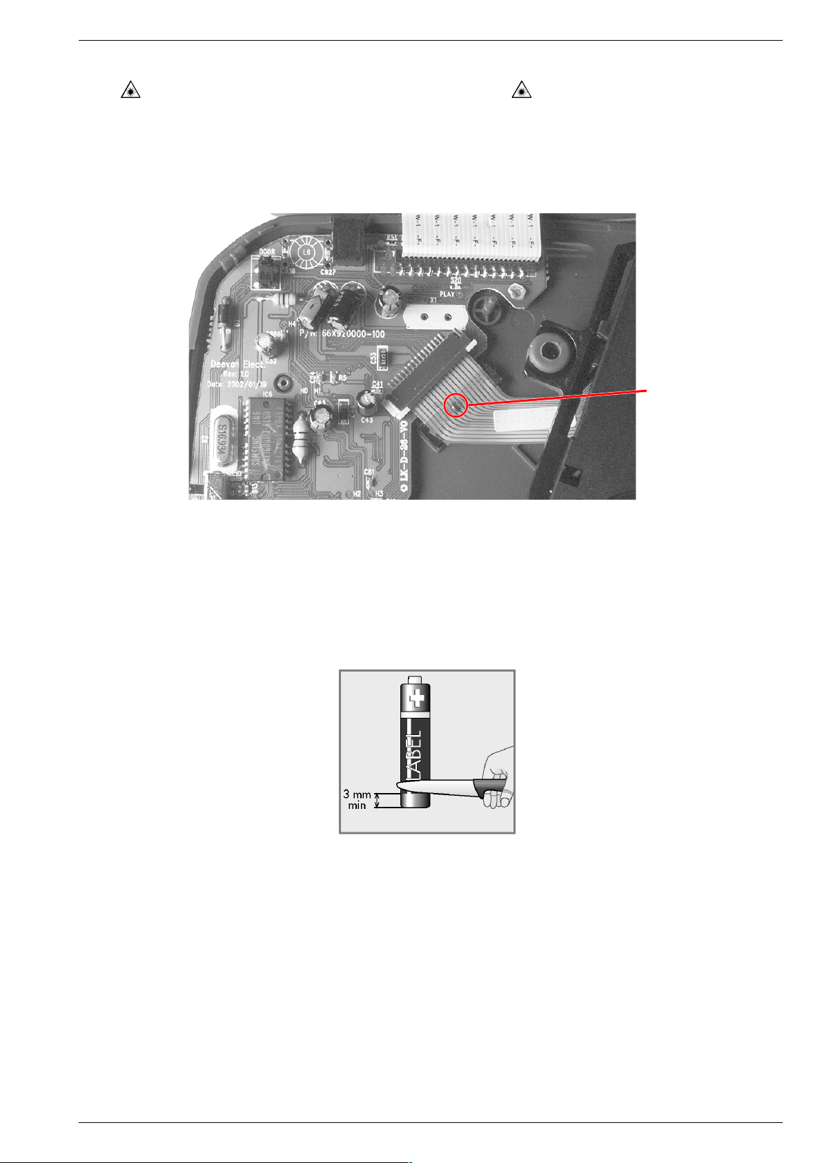
Bei Ausbau der CD-Lasereinheit muss vor Abziehen der Steckverbindungen eine Schutzlötstelle auf dem Flexprint der Lasereinheit
angebracht werden, um eine Zerstörung der Laserdiode durch statische Aufladung zu vermeiden.
Beim Einbau einer neuen Lasereinheit (CD-Laufwerk) muss
nach Einstecken der Steckverbinder die werkseitig angebrachte
Schutzlötstelle entfernt werden!
Service Hints
CD Section
When removing the Laser pick-up, the Laser pick-up flexprint must be
provided with a protective soldered joint before unplugging the
connectors to avoid damage to the Laser diode by static charges.
When inserting the new Laser pick-up (CD drive mechanism) the
soldered joint fitted at the factory must be removed after the
connectors are plugged in.
Schutzlötstelle
protective soldered joint
Betrieb mit Nickel-Cadmium-Akkus
Beim Betrieb mit Nickel-Cadmium-Akkus (NiCd, Größe AA 1,2V/
600mAh) können Sie den mitgelieferten Netzadapter als Ladegerät
verwenden.
Bei den Akkus muss das Metallende am Minuspol ca. 3mm sichtbar
sein (siehe Abbildung). Gegebenenfalls die Isolierung mit einem
Messer entfernen. Über diese Kontaktfläche erkennt das Gerät, dass
Akkus eingelegt sind. Damit wird verhindert, dass versehentlich Batterien aufgeladen werden.
Neue Pick-Up-Einheit
Bei Geräten ab Seriennummern 14289 wurde eine neue Pick-UpEinheit (DA23Z an Stelle von DA23L) eingebaut. Dadurch ändern sich
4 Widerstandswerte (siehe Schaltbild Seite 2 - 1).
Bitte beachten Sie auch die unterschiedlichen Materialnummern in der
Ersatzteilliste!
Wird als Ersatz für DA23L ein DA23Z eingebaut, müssen die
Widerstandswerte von R20 -R23 entsprechend geändert werden!
DA23L DA23Z
R20 180kΩ 150kΩ
R21 3,9kΩ 5,6kΩ
R22 82kΩ 39kΩ
R23 220kΩ 180kΩ
Using Nickel-Cadmium Accus
When using Nickel-Cadmium accus (NiCd, size AA 1.2 V/600 mAh)
use the mains adapter included as a charger.
The metal end at the negative pole of the accus must be visible for
approximately 3mm (see illustration). If necessary, use a knife to
remove the insulation. Via this contact the unit detects inserted accus.
This prevents a charging of normal batteries by mistake.
New Pick Up Unit
In the sets from serial number 14289 on, a new pick up unit (DA23Z
instead of DA23L) is used. Therefore the values of 4 resistors change
(see circuit diagram page 2 - 1).
Please observe also the different parts numbers in the spare parts list!
If DA23L will be replaced by DA23Z the resistors R20 - R23 must also
be changed to the corresponding values.
DA23L DA23Z
R20 180kΩ 150kΩ
R21 3,9kΩ 5,6kΩ
R22 82kΩ 39kΩ
R23 220kΩ 180kΩ
GRUNDIG Service 1 - 3
Page 4
Allgemeiner Teil / General Section MYSTIXX CDP 9200 SPCD
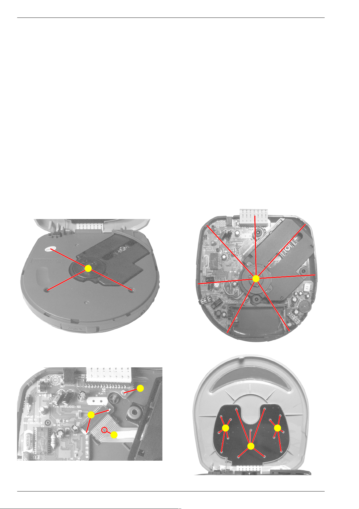
Ausbauhinweise
1. Gehäuseoberteil
- CD-Fach öffnen.
- 3 Schrauben A herausschrauben (Fig. 1).
- 7 Rastungen B ausrasten (Fig. 2).
- Achtung:
Kurze Flexprintleitung von der Hauptplatte zum Bedienteil.
Gehäuseoberteil vorsichtig nach hinten klappen und Flexprintleitung von der Hauptplatte abziehen.
- Geäuseoberteil abnehmen.
2. CD-Laufwerk, Hauptplatte, Lautstärkereglerplatte
- Gehäuseoberteil abnehmen (Punkt 1).
- Fixierung C (Fig. 3) vorsichtig mit Schraubendreher abtrennen.
- Die beiden Leiterplatten und das Laufwerk können aus dem
Gehäuseunterteil genommen werden. Achtung! Die Flexprintleitung ist am Gehäuseboden festgeklebt.
Hinweise:
- Vor Abziehen der Flexprintleitung, Sicherheitslötstelle D (Fig. 3)
kurzschließen.
Flexprinthalter öffnen E (Fig. 3) und Flexprint abziehen.
- Nach dem Anschließen eines neuen Laufwerks werkseitig ange-
brachte Sicherheitslötstelle auflöten.
3. Bedienplatte
- Achtung: Kurze Flexprintleitung bei Bedarf auf der Hauptplatte
abziehen. Zum Abziehen der Flexprintleitung Gehäuseoberteil abnehmen (Punkt 1).
- 15 Schrauben F (Fig. 4) herausschrauben.
- Bedienplatte abnehmen.
Disassembly Instructions
1. Top of the Case
- Open the CD compartment.
- Undo 3 screws A (Fig. 1).
- Disengage 7 hooks B (Fig. 2).
- Attention:
Short flexprint between main PCB and operating PCB.
Carefully tip the top of the case back and pull off the flexprint from
the main PCB.
- Remove the top of the case.
2. CD Mechanism, Main PCB, Volume Control PCB
- Remove the top of the case (point 1).
- Carefully cut off the fixing point C (Fig. 3) by a screw driver.
- Both PCBs and the mechanism now are able to remove. Attention!
The flexprint is glued at the bottom.
Hints:
- before unplugging the flexprint, short circuit the safety soldered
joint D (Fig. 3).
Open the flexprint connector E (Fig. 3) and pull off the flexprint.
- After a new mechanism is connected the safety soldered joint
fitted at the factory must be removed.
3. Operating PCB
- Attention: When necessary pull off the short flexprint at the main
PCB. Therefore remove the top of the case (point 1).
- Undo 15 screws F (Fig. 4).
- Remove the operating PCB.
A
Fig. 1 Fig. 2
C
E
D
B
F F
F
Fig. 3 Fig. 4
1 - 4 GRUNDIG Service
Page 5
MYSTIXX CDP 9200 SPCD Allgemeiner Teil / General Section
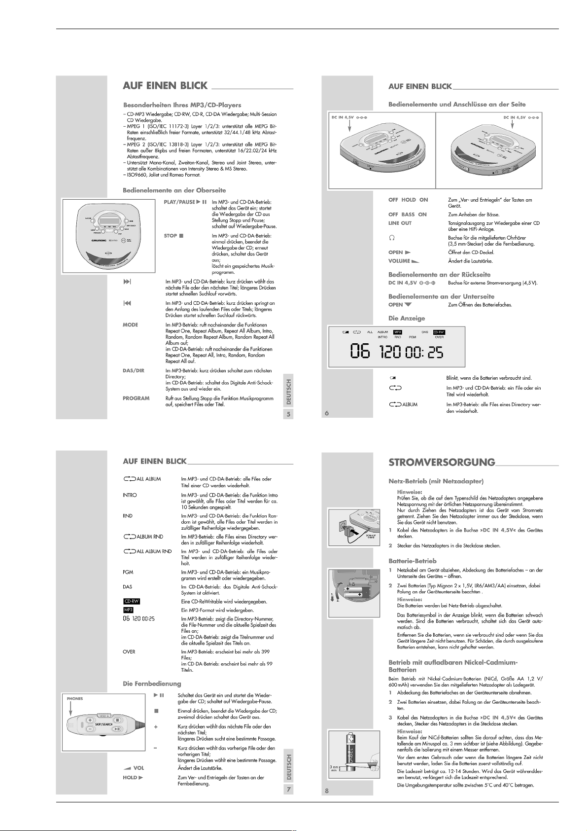
Bedienhinweise Dieses Kapitel enthält Auszüge aus der Bedienungsanleitung. Weitergehende Informationen entnehmen Sie bitte der
gerätespezifischen Bedienungsanleitung, deren Materialnummer Sie in der entsprechenden Ersatzteilliste finden.
GRUNDIG Service 1 - 5
Page 6

Allgemeiner Teil / General Section MYSTIXX CDP 9200 SPCD
1 - 6 GRUNDIG Service
Page 7

MYSTIXX CDP 9200 SPCD Allgemeiner Teil / General Section
Operating Hints This chapter contains excerpts from the operating instructions. For further particulars please refer to the appropriate user
instructions the part number of which is indicated in the relevant spare parts list.
GRUNDIG Service 1 - 7
Page 8

Allgemeiner Teil / General Section MYSTIXX CDP 9200 SPCD
1 - 8 GRUNDIG Service
Page 9

Platinenabbildungen und Schaltpläne / Layout of PCBs and Circuit Diagrams Platinenabbildungen und Schaltpläne / Layout of PCBs and Circuit DiagramsMYSTIXX CDP 9200 SPCD MYSTIXX CDP 9200 SPCD
C
5
12
37
Platinenabbildungen und Schaltpläne / Layout of PCBs and Circuit Diagrams
Schaltplan / Circuit Diagram
IC 2
R20, R22, R23, R31:
Werte mit * bei Seriennummern
≤ 14288 (Pick-Up-Einheit DA23L)
Values with * at serial numbers
≤ 14288 (Pick Up Unit DA23L)
Werte mit ** bei Seriennummern
≥ 14289 (Pick-Up-Einheit DA23Z)
Values with ** at serial numbers
≥ 14289 (Pick Up Unit DA23Z)
Pickup
CN1
CON7
E
16
C
15
A
14
D
13
B
12
F
11
VREF
10
SVCC
9
GND
8
LD
7
PD
6
VR
5
TE-
4
FE-
3
FE+
2
TE+
1
TE+
1,6V
3,2V
FE+
FE-
IC 4
3,2V
SADT1
LRCK1
VCC2
BCK1
DACCLK
BCK2
LRCK2
SADT2
D0
D1
WE
RAS
A10
A0
A1
A2
A3
C19
104
C13
104
3,2V
3,2V
1
2
3
4
5
6
7
8
9
10
11
12
C31
470P
C38
333
PDA
PDC
PDB
PDD
PDF
PDE
VREF
VCC
EQC
LPB
LPC
TESO
RFM2
RFM
RFO
EQI
C35
683
R22
82K*
39K**
48
TZC
TEIO
LPF1
LPF2
LD
PD
DCC13DCC2
EFMI
EQO
MCP
DCB
1
2
6
4
5
C59
103102103 104
R20
180K*
150K**
R23
220K*
180K**
ATSC
IC2
S1L9225
GND
7
0V
3,2V
TEO
FRSH
8
VCC1
TEM
FSET
9
+
SLP
FLB
10
C53
4.7uF
SLO
FGD
11
FEO
SLM
FDFCT
FSEO
12
13
C33
C37
103
C43
47uF
C41
102
A
C
B
D
F
E
+
C46
C920
C921
3P
R31
3K9*
5K6**
R910
100
R32
8.2K
R27
22
Q8
2N2907
C54
+
100uF
C62
+
100uF
R977 82
TE-
103
473
NOP
C34
102
R19
47K
C39
222
49
50
51
52
53
54
55
1,6V
56
3,2V
57
58
59
60
61
62
63
64
C48
103
C100
820P
C52 C58 C55
FEM
FSI
14
SPO
ATO
+
R25 68K
C42
333435363738394041424344454647
SPM
VDD
VSS
SSTOP
EFM
EFM2
ASY
LOCK
CLVI
WDCK
XRST
MLT
MDAT
MCK
ISTAT1
ISTAT
VDD
TGU
15
16
683C36
47KR21
10uFC32
103C40
15KR24
27K
R26
104
68K
R28
22KR29
100
R30
32
3,2V
31
0V
30
29
28
27
26
25
24
23
22
21
20
19
18
17
3,2V
C51C50 C56 C57
102104 104
104
LIMSW
1,6V
VREF
ISTAT
ISTAT1
C45
C44
+
2.2uF
332
R33 8.2K
C61
474
C60
333
R35
22K
R37
R34
22K
R36
1M
22K
SLO
SPO
FEO
TEO
C4M
C84
820P
17
VDD
18
ACLKEXT
19
CDCLK
20
CDDATA
21
CDLRCK
22
CDBCK
23
CDC2PO
24
ACLK
25
BCLK
26
LRCK
27
ADAT
28
EMP
29
ETYPE
30
NC
31
NC
32
VSS
IC6
VCC
D0
D1
WE#
RAS#
NC
16MDRAM
A10
A0
A1
A2
A3
VCC
16
VSS
VDD
33
3,2V
CAS#
14
15
FILTER1
PBYPAS
MCUCLK
MDAT
34
35
MDATA
VSS
D3
D2
OE#
A9
A8
A7
A6
A5
A4
VSS
C22
104
13
PLL1VSSA
PLL1VBBA
I
S
MLAT
MCK
36
MLATCH
MCK
24
23
22
21
20
19
18
17
16
15
14
13
GRUNDIG Service GRUNDIG Service
2 - 22 - 1
Page 10

Platinenabbildungen und Schaltpläne / Layout of PCBs and Circuit Diagrams Platinenabbildungen und Schaltpläne / Layout of PCBs and Circuit Diagrams MYSTIXX CDP 9200 SPCDMYSTIXX CDP 9200 SPCD
DACCLK
BCK1
LRCK1
SADT1
LRCK2
BCK2
SADT2
10
11
FILTER0
MINT
38
39
MINT
C82
820P
3,2V
7
9
PLL0VDDA
PLL0VSSA8RESETB
PLL0VBBA
SCAN_EN
TEST241TEST142TEST0
40
5
6
CLK
DDAT044DDAT1
43
D0
3,2V
X2
16.9344
3,2V
4
VDD1XI2XO3XOUT
64
VSS
63
OEB
62
DA03
61
DA02
60
DA01
59
DA00
58
DA09
57
DA04
56
DA05
55
DA06
54
DA07
53
DA08
52
CASB
51
DDAT3
50
DDAT2
49
VDD
RASB
WEB
VSS
47
48
45
46
RAS
WE
D1
3,2V
A3
A2
A1
A0
A9
A4
A5
A6
A7
A8
CAS
D3
D2
C68
104
D0
D1
WE
RAS
D2
D3
CAS
A10
A8
A7
A6
A5
A4
A9
A0
A1
A2
A3
3,2V
61
62
63
64
65
66
67
68
69
70
71
72
73
74
75
76
77
78
79
80
C78
104
VDD
D0
D1
WE
RAS
D2
D3
CAS0
CAS1(A10)
A8
A7
A6
A5
A4
A9
A0
A1
A2
A3
VSS
C20
820P
59
60
MINT4
MINT5
VSS
VDDAPLL
VSSAPLL
VBBAPLL
123
3,2V
58
MINT3
VCO1LF
57
456
55
56
MINT1
MINT2
VSSDPLL
VCO2LF
C21
820P
53
54
RFCK
MINT0
IC3
S5L9288
VDDDPLL
VDDD1
PBCK
789
3,2V
52
JITB51C2PO
XIN
3,2V
XOUT
101112
50
VDD49DATX
VSSD1
TEST0
48
C4M47VSSD2
EFMI
131415
46
SBDT
LOCK
45
MUTE
SBCK
SMON
SMEF
161718
44
43
TEST3
SMDP
42
TEST1
TEST2
WDCK
SMSD
19
3,2V
41
20
VSS
VDDDDAC
RCHOUT
VSSADAC
VREF
VHALF
VDDADAC
LCHOUT
SQDT
SQCK
SOSI
ISTAT
MCK
MDATA
MLT
XRST
LKFS
WFCK
TESTV
VDD
C81
104
14
15
FILTER1
PBYPAS
MCUCLK
MDAT
35
34
MDATA
C22
104
3,2V
12
13
PLL1VDDA
PLL1VSSA
PLL1VBBA
IC4
S5L9276
MLAT
MDO
MCK
36
37
MLATCH
MDOUT
MCK
C981
NOP
C71
200
200
10K
10K
2.2K
2.2K
10
9
8
7
6
C66
220u
C76
224
3,0V
1,1V
0V
1,1V
3,0V
1uF
+
C70
1uF
+
+
+
+
C72
4u7
C73
4u7
R978
100K
R979
100K
C508
102
C507
102
LINE
1
2
3
IC 7
1
2
4
R961
4R7
R962
4R7
BBS
3
C611
220uF
C612
220uF
+
+
224C610
224C609
R606 C926
200
R607
200
102
C925
102
1
2
3
PHONE
++
C75
224
R41
C28
C27
1uF
1uF
R42
5
1
IC7
LA4534M
R617
NOP
R46
R45
R44
R43
4
VOL
10K A
M/SW
OUT1
GND
OUT2
VCC
40
39
3,0V
38
37
36
35
34
3,0V
33
32
SUBQ
31
SQCK
30
SCOR
29
DSENS
28
MCK
27
MDATA
26
MLT
25
XRST
24
23
22
21
3,2V
CDMUTE
2
3
1
3,0V
P/SW
2
1,1V
IN1
3
0V
GND
4
1,1V
IN2
5
1,1V
REF
+
C908
47uF
24
0V
VSS
23
D3
22
D2
21
CAS
20
19
A9
18
A8
17
A7
16
A6
15
A5
14
A4
13
0V
D0
D1
WE
RAS
A9
A0
A1
A2
A3
1
2
3
4
5
6
7
8
9
10
AS#
OE#
VSS
D3
D2
A9
A8
A7
A6
A5
A4
2 - 3 2 - 4
D0
D1
WE#
RAS#
A9
A0
A1
A2
A3
VCC
NOP
4MDRAM
VSS
CAS#
OE#
20
19
D3
D2
A8
A7
A6
A5
A4
D3
18
D2
17
CAS
16
15
A8
14
A7
13
A6
12
A5
11
A4
GRUNDIG Service GRUNDIG Service
BUS
VCC3
M/SW
IC 6
zu Seite 2 - 5
to page 2 - 5
Page 11

3
3
zu Seite 2 - 4
to page 2 - 4
Platinenabbildungen und Schaltpläne / Layout of PCBs and Circuit Diagrams Platinenabbildungen und Schaltpläne / Layout of PCBs and Circuit DiagramsMYSTIXX CDP 9200 SPCD MYSTIXX CDP 9200 SPCD
IC 5
SLED
Limit-SW
SPINDLE
DC/JK
CN2
6
5
4
3
2
1
CON6
1
2
3
CHARGE
SLSL+
LIMSW
SP+
SP-
Q1
2SA1585SR
IN5818
R15
56
LIMSW
7,1V
2,5V (Batt.)
34
R2
100K
102
RST#OUT
35
EMP
36
HVCC
37
PWM
38
CLKIN
39
START
40
OFF
41
ADPVCC
42
EMPSET
43
PGND
44
FIL
C2
L1 39uH
0,8V
D1
C1
1N5818
R1 47
D7
BATT
BATTERY
+
100uF
33
CHGSET
OVP
1
R4 22K
C5
104
32
CH1(-)
BATT
2
104 470uF
CH2(-)
CH1(+)
IC5
FAN8038
RSTOUT
DEDSET
4
3
293031
PGND
CH2(+)
BDSW
ERRO
5
C8
332
+
TE+
27
28
CH3(+)
ERRI
7
6
C6
R3 100
TE-
FE+
FE-
242526
CH4(-)
CH4(+)
CH3(-)
COSC
SCP
NC
10
8
9
C7
+
1uF
102
7,4V
2,7V (Batt.)
23
BRK1
OP(-)
11
C9
470P
KTD1303
C69
104
CH1IN
MUTE2
CH2IN
MUTE34
CH4IN
CH3IN
VREF
SVCC2
OP(+)
OPOUT
SVCC1
C10
+
IuF
Q2
22
21
20
19
1,6V
18
17
16
1,6V
15
3,2V
14
13
12
3,2V
R7 4.7K
R6
390K
7,2V
2,6V (Batt.)
L2
100/2uH
C11
47P
VREF
R8R922K
R10
R11
22K
22K
22K
SLO
SPO
FEO
TEO
3,0V
Q4
2AM3906
C15
+
100uF
C16
104
3,2V 3,2V
C88
L3
100uH
Q3
KTD1303
R12 10
C14 104
R13
IK
+
C12
470uF
C26
104104
SLO
SPO
FEO
TEO
VCC1
3,2V
+
100uF
C63
VCC3
3,0V
ISTAT1
ISTAT
C4M
VCC2
3,2V
HOLD
1
3
DOOR
1
3
LCDTEST
BBSOPT0
BBSOPT1
P/U OPT
C87
104C4C3
M/SW
LCD
SEG19
SEG1621SEG1722SEG18
SEG1318SEG1419SEG15
COM23COM3
COM01COM1
SEG0
SEG49SEG510SEG6
SEG16SEG27SEG3
2
2
1
SEG26/P5.2
2
SEG27/P5.3
3
SEG28/P5.4
4
SEG29/P5.5
5
SEG30/P5.6
6
SEG31/P5.7
7
P3.0/TBPWM
8
P3.1/TAOUT/TAPWM
9
P3.2/TACLK
10
P3.3/YACAP/SDAT
11
P3.4/SCLK
12
3,2V
VDD
13
VSS
14
XOUT
15
XIN
16
TEST
17
XTIN
18
XTOUT
19
RESET#
20
P0.0/INT0
2
COM0
COM1
80
SEG23/P4.7
SEG24/P5.0
SEG25/P5.1
P0.1/INT1
P0.2/INT2
P0.3/INT3
4
5
COM2
COM3
SEG0
SEG20
75
76
777879
SEG20/P4.4
SEG21/P4.5
SEG22/P4.6
P0.4/INT4
P0.5/INT5
P0.6/INT6
8
SEG1
SEG2
SEG3
SEG19
SEG17
SEG18
SEG17/P4.1
SEG18/P4.2
SEG19/P4.3
P1.0/T1CAP
P1.1/T1CLK
P0.7/INT7
SEG4
SEG5
SEG15
SEG16
7065727374
SEG15
SEG16/P4.0
IC1
S3C8249
P1.2/T1OUT/T1PWM
P1.3
SEG712SEG813SEG9
11
SEG7
SEG6
SEG13
SEG14
68
69
SEG13
SEG14
P1.4/BUZ
P1.5/SO
14
SEG9
SEG8
SEG11
SEG12
67
SEG11
SEG12
P1.6/SCK
P1.7/SI
SEG1015SEG1116SEG12
17
SEG12
SEG13
SEG10
SEG11
SEG7
SEG8
SEG9
SEG10
646566
SEG7
SEG8
SEG9
SEG10
P2.3/ADC3
P2.0/ADC0
P2.1/ADC1
P2.2/ADC2
20
SEG18
SEG15
SEG16
SEG17
SEG14
SEG6
616263
SEG6
SEG5
SEG4
SEG3
SEG2
SEG1
SEG0
COM3
COM2
COM1
COM0
VLC2
VLC1
VLC0
AVSS
AVref
P2.7/ADC7/Vvldref
P2.6/ADC6
P2.5/ADC5
P2.4/ADC4
23
CA
CB
24
SEG20
SEG19
60
59
58
57
56
55
54
53
52
51
50
49
48
47
46
45
44
43
42
41
Spannungen gemessen bei Netzteilbetrieb
Voltages measured at operation with mains unit
212223
242526
272829
33
30
31
32
34
353637
383940
IC 1
GRUNDIG Service GRUNDIG Service
R52
22K
MINT
MLATCH
MDOUT
CDMUTE
SCOR
DSENS
MCK
MDATA
MLT
XRST
SQCK
SUBQ
ESPOPT1
ESPOPT2
ESPOPT0
ESPOPT3
2 - 62 - 5
Page 12

Platinenabbildungen und Schaltpläne / Layout of PCBs and Circuit Diagrams Platinenabbildungen und Schaltpläne / Layout of PCBs and Circuit Diagrams MYSTIXX CDP 9200 SPCDMYSTIXX CDP 9200 SPCD
PICK UP
PORTABLE
4CH
MOTOR
DRIVER
SANYO
DA23
RF-AMP+SSP
DSP+DAC+ESP+1BIT DAC
9288D
CD-MP3
DECODE
9276
DRAM 16M
MICOM
9225
S3C8249XZZ
LCD
KEY
PHONE
AMP
LA4534M
DISC
DOOR
CLOSE
SW
HOLD
SW
PHONE
BUS
Display- und Bedien-Platte
Display and Operating Board
Sicht auf Bestückungsseite
View on Component Side
SEG19
G5
G4
G3
G2
G1
G0
M3
M2
M1
M0
C2
C1
C0
CA
CB
SS
ref
ref
C6
C5
24
SEG20
SEG19
D5 1N4148
7,1V
2,5V (Batt.)
C930
+
D3 1N4148
C929
224
R59
2K7
PLAY
R53
100K
60
59
58
57
56
55
54
53
52
51
50
49
48
47
46
45
44
43
42
41
3,2V
3,2V
SEG5
SEG4
SEG3
SEG2
SEG1
SEG0
COM3
COM2
COM1
COM0
R50
100K
R48
100K
C85
+
100uF
S1
DAS
S5
STOP
S6
S7
BACK
S8
NEXT
R10
390
R9
560
R7
680
R12
1K
Q5
2N3904
R58
27K
R18
820K
S14
+
S11
S12
S13
PLAY
STOP
BACK
NEXT
R39
820K
Q6
2N39061uF
7,4V
2,6V (Batt.)
R960
470K
D2
1N4148
R1
4K7
R2
6K8
R3
10K
R4
12K
Blockschaltplan / Block Diagram
MODE
S9
ESPOPT2
ESPOPT3
2 - 7 2 - 8
S10
PROG
R3
2.2K
GRUNDIG Service GRUNDIG Service
Page 13

MYSTIXX CDP 9200 SPCD Platinenabbildungen und Schaltpläne / Layout of PCBs and Circuit Diagrams
Haupt-Platte / Main Board
Sicht auf Bestückungsseite
View on Component Side
Für die tatsächliche Bauteilbestückung ist das
The circuit diagram is relevant for the actual
GRUNDIG Service 2 - 9
Schaltbild maßgebend!
component assembly!
Page 14

Platinenabbildungen und Schaltpläne / Layout of PCBs and Circuit Diagrams MYSTIXX CDP 9200 SPCD
Haupt-Platte / Main Board
Sicht auf Lötseite
View on Solder Side
Für die tatsächliche Bauteilbestückung ist das
The circuit diagram is relevant for the actual
2 - 10 GRUNDIG Service
Schaltbild maßgebend!
component assembly!
Page 15

GRUNDIG Service 3 - 1
Explosionszeichnung und Ersatzteilliste / Exploded View and Spare Parts List
MYSTIXX CDP 9200 SPCD Explosionszeichnung und Ersatzteilliste / Exploded View and Spare Parts List
Page 16

3 - 2 GRUNDIG Service
Ersatzteilliste
Spare Parts List
Explosionszeichnunge und Ersatzteilliste / Exploded View and Spare Parts List MYSTIXX CDP 9200 SPCD
ǵ
AUDIO
8 / 2002
POS. NR. ABB. MATERIAL-NR. ANZ. BEZEICHNUNG DESCRIPTION
POS. NO. FIG. PART NUMBER QTY.
755105105000 MYSTIXX CDP 9200 SPCD MYSTIXX CDP 9200 SPCD
0001.000 1 759550525600 RING TUER CD RING DOOR CD
0002.000 1 759550525700 TUER CD DOOR CD
0003.000 1 759550525800 KNOPF LINKS KNOB LEFT
0004.000 1 759550525900 KNOPF RECHTS KNOB RIGHT
0005.000 1 759550526000 LINSE DISPLAY LENS DISPLAY
0008.000 1 759550525500 BEDIENPLATTE MIT DISPLAY KPL CONTROL BORD WITH DISPLAY CPL
0009.000 1 759550524000 7 DRUCKKONTAKT D6 PUSH CONTACT D6
0010.000 1 759550526100 LINSE DISC LENS DISC
0014.000 1 759540586000 KLINKENBUCHSE SCHWARZ 3,5 LI SOCKET LINE OUT BLACK 3,5MM
0015.000 1 759550521700 BUCHSE DC 1,3MM SOCKET DC 1,3MM
0017.000 1 759550526200 FEDER TUER SPRING DOOR
0018.000 1 759550526300 GEH-OBERTEIL CABINET UPPER PART
0019.000 1 759550524100 DAEMPFER DAMPER
0020.000 1 759550520800 KNOPF OPEN KNOB OPEN
0021.000 1 759550524300 BATTERIE KONTAKT + - BATTERY CONTACT + -
0022.000 1 759550524200 FEDERPLATTE BATTERIE SPRING PLATE BATTERY
0024.000 1 759550525300 CD LAUFWERK DA23L CD MECHANISM DA23L
0024.000 1 759550526700 CD LAUFWERK DA23Z AB SERIENNR.14289 CD MECHANISM DA23Z FROM SERIAL NO.14289
0026.000 1 759550521400 3 PUFFER CUSHION
0029.000 1 759550520700 KNOPF BASS KNOB BASS
0030.000 1 759550526400 GEH-UNTERTEIL CABINET LOWER PART
0034.000 1 759550526500 TUER BATTERIE DOOR BATTERY
0035.000 1 759550524400 KLINKENBUCHSE GRUEN 3,5MM EAR PHONE SOCKET GREEN 3,5MM
0045.000 759550524800 FERNBEDIENUNG KOPFHOERER REMOTE CONTROL HEADPHONE
0050.000 S 759550520100 STECKERNETZTEIL 4,5V/0,5A/0,7W POWER SUPPLY 4,5V/0,5A/0,7W
720114015500 BEDIENUNGSANLEITUNG OPERATING INSTUCTION
720107723000 SERVICE MANUAL D /GB SERVICE MANUAL D/GB
POS. NR. MATERIAL-NR. BEZEICHNUNG
POS. NO. PART NUMBER DESCRIPTION
d©
KEIN E-TEIL NO SPARE PART
D/GB/F/I/P/E/NL/DK/S/FIN D/GB/F/I/P/E/NL/DK/S/FIN
MYSTIXX CDP 9200 SPCD
MATERIAL-NR. / PART NO.: 755105105000
BESTELL-NR. / ORDER NO.: GDN9550
POS. NR. MATERIAL-NR. BEZEICHNUNG
POS. NO. PART NUMBER DESCRIPTION
D 1 759550524500 DIODE IN5818
D 2 759550524500 DIODE IN5818
D 3 832500414800 SMD DIODE LS 4148
D 5 832500414800 SMD DIODE LS 4148
IC 1 759550526600 IC S3C8249ZZ
IC 2 759550524900 IC KA9225QFP
IC 3 759550525100 IC S5L9288
IC 4 759550525000 IC S5L9276X01-EO
IC 5 759550523400 SMD IC FAN8038B QFP44
IC 7 759550525400 IC LA4534M
IC NOP 759550525200 IC 4MDRAM (K4E1604110-BC60)
L 1 759550521900 DR.39UH
L 2 759550521800 DR.100UH 3PIN
L 4 759520307800 DR 0309 100UH 5% AX LALO3TB
Es gelten die Vorschriften und Sicherheitshinweise
gemäß dem Service Manual "Sicherheit", Mat.-Nummer 720108000000, sowie zusätzlich die eventuell abweichenden, landesspezifischen Vorschriften!
Q 1 759550524700 TRANS 2SA1585SR
Q 2 759550522000 TRANS KTD1303-KEC
Q 3 759550522000 TRANS KTD1303-KEC
Q 4 759550524600 SMD TRANS KTA1270
Q 8 759880513300 TRANS KTA1266Y (TP)
R VOL 759550522400 EINSTELLREGLER 10KOHM+-20%
SW BBS 759550522300 SCHIEBESCHALTER 2P2T TECX
SW DOOR 759550522100 SCHALTER DTS-03
SW HOLD 759550522200 SCHIEBESCHALTER 1P2T TECX
X 2 759520113400 QUARZ 16,9344 MHZ
The regulations and safety instructions shall be valid
!
as provided by the "Safety" Service Manual, part
number 720108000000, as well as the respective
( ! )
national deviations.
ÄNDERUNGEN VORBEHALTEN / SUBJECT TO ALTERATION
 Loading...