

Page 1
Service
Manual
HiFi Service Manual
Apollo 2000
G.NK 0150
Zusätzlich erforderliche Unterlagen für den Komplettservice
Additionally required Service Documents for the Complete Service
Sicherheit
Safety
Materialnr./Part No.
72010 800 0000
Materialnummer/Part Number 72010 760 7500
Änderungen vorbehalten/Subject to alteration • Printed in Germany
E-BS 36 0500 • 8002/8012, 8005/8015, 8006/8016
http://www.grundig.com
Grundig Service
Hotline Deutschland...
Technik:
TV
TV
SAT
VCR/LiveCam
HiFi/Audio
Car Audio
Telekommunikation
Planatron
Ersatzteil-Verkauf: ...Mo.-Fr. 8.00-19.00 Uhr
(8.00-22.00 Uhr)
...Mo.-Fr. 8.00-18.00 Uhr
0180/52318-41
0180/52318-49
0180/52318-48
0180/52318-42
0180/52318-43
0180/52318-44
Fax:
Telefon:
Fax:
0180/52318-45
0180/52318-51
0180/52318-99
0180/52318-40
0180/52318-50
Page 2

Allgemeiner Teil / General Section
Apollo 2000
Es gelten die Vorschriften und Sicherheitshinweise
gemäß dem Service Manual "Sicherheit", Materialnummer 72010 800 0000, sowie zusätzlich die eventuell abweichenden, landesspezifischen Vorschriften!
Inhaltsverzeichnis
Seite
Allgemeiner Teil ............................ 1 - 2 … 1 - 6
Servicehinweis ................................................................................. 1 - 2
Technische Daten ............................................................................ 1 - 2
Ausbauhinweise............................................................................... 1 - 3
Bedienhinweise................................................................................ 1 - 5
Schaltpläne und
Druckplattenabbildungen........... 2 - 1 … 2 - 10
Verdrahtungsplan............................................................................. 2 - 1
Schaltpläne
NF-Verstärker-Platte .................................................................... 2 - 5
Control-Platte ............................................................................... 2 - 7
Netzteil ....................................................................................... 2 - 10
Druckplattenabbildungen
NF-Verstärker-Platte .................................................................... 2 - 3
Control-Platte ............................................................................... 2 - 3
Netzanschluß-Platte................................................................... 2 - 10
Netzschalter-Platte..................................................................... 2 - 10
The regulations and safety instructions shall be valid
as provided by the "Safety" Service Manual, part
number 72010 800 0000, as well as the respective
national deviations.
Table of Contents
Page
General Section............................. 1 - 2 … 1 - 8
Service Hint...................................................................................... 1 - 2
Technical Data ................................................................................. 1 - 2
Disassembly Instructions ................................................................. 1 - 3
Operating Hints ................................................................................ 1 - 7
Circuit Diagrams and
Layout of PCBs ........................... 2 - 1 … 2 - 10
Wiring Diagram ................................................................................ 2 - 1
Circuit Diagrams
Power Amplifier Board ................................................................. 2 - 5
Control Board............................................................................... 2 - 7
Power Supply............................................................................. 2 - 10
Layout of PCBs
Power Amplifier Board ................................................................. 2 - 3
Control Board............................................................................... 2 - 3
Mains Con Board ....................................................................... 2 - 10
Mains Switch Board ................................................................... 2 - 10
Explosionszeichnung
und Ersatzteilliste ......................... 3 - 1 … 3 - 2
Allgemeiner Teil
Messgeräte / Messmittel
Beachten Sie bitte das GRUNDIG Messtechnik-Programm, das Sie unter
folgender Adresse erhalten:
GRUNDIG Instruments Test- und Messsysteme GmbH
Würzburger Str. 150, D 90766 Fürth/Bay
Tel. 0911/703-4118, Fax 0911/703-4130
eMail: instruments@grundig.de; Internet: http://www.grundig-instruments.de
Servicehinweis
Die Daten- und Analog-Funkmodule dürfen nur durch autorisierte
Fachbetriebe repariert werden und müssen daher im Defektfall komplett getauscht werden.
Exploded View and
Spare Parts List............................. 3 - 1 … 3 - 2
General Section
Test Equipment / Aids
Please note the Grundig Catalog "Test and Measuring Equipment" obtainable from:
Service Hint
The Data and Analog RF Modules are allowed to be repaired only by
authorized dealers and are to be exchanged completely in case of any
defect.
Technische Daten
Sinusleistung.................................................................................. 200W
Musikleistung ................................................................................. 360W
Eingangsempfindlichkeit / Impedanz ................................ 500mV / 47kΩ
Signal-Rausch-Abstand ................................................................ >95dB
Klirrfaktor (-1db, 8Ω, 1kHz) ........................................................... 0,01%
Netz................................................................................. 230V / 50/60Hz
Leistungsaufnahme........................................................................ 360W
Standby Leistungsaufnahme ........................................................... <2W
Eingang für Vorverstärker ......................................................... 1 x cinch
Frequenz der NF-Übertragung........................................ 863 … 865MHz
Frequenz der Datenübertragung......................................868 … 870MHz
Lautsprecher .......................................................................................... 4
Übertragungsbereich ...................................................... 30Hz … 25kHz
Übernahme-Frequenzen ............................................... 200Hz / 5.000Hz
1 - 2 GRUNDIG Service
Technical Data
Nominal power ............................................................................... 200W
Music power ................................................................................... 360W
Input sensitivity / impedance ............................................. 500mV / 47kΩ
Signal-to-noise ratio ...................................................................... >95dB
Distortion (-1db, 8Ω, 1kHz) ........................................................... 0.01%
Mains .............................................................................. 230V / 50/60Hz
Power consumption ....................................................................... 360W
Standby power consumption............................................................ <2W
Pre-amp in ................................................................................ 1 x cinch
Frequency for audio transmission................................... 863 … 865MHz
Frequency for data transmission..................................... 868 … 870MHz
Number of speakers............................................................................... 4
Transmission range ........................................................ 30Hz … 25kHz
Crossover frequency ..................................................... 200Hz / 5.000Hz
Page 3
Apollo 2000 Allgemeiner Teil / General Section
Ausbauhinweise
Leitungsverlegung
Bevor Sie die Leitungen und insbesondere die Masseleitungen lösen,
muss die Leitungsverlegung zu den einzelnen Baugruppen beachtet
werden.
Nach erfolgter Reparatur ist es notwendig, die Leitungsführung wieder
in den werkseitigen Zustand zu versetzen um evtl. spätere Ausfälle
oder Störungen zu vermeiden.
Die angegeben Zahlen beziehen sich auch auf die Explosionszeichnung. Den Ausbau der Gehäuseteile entnehmen Sie bitte der
Explosionszeichnung (Seite 3 - 1).
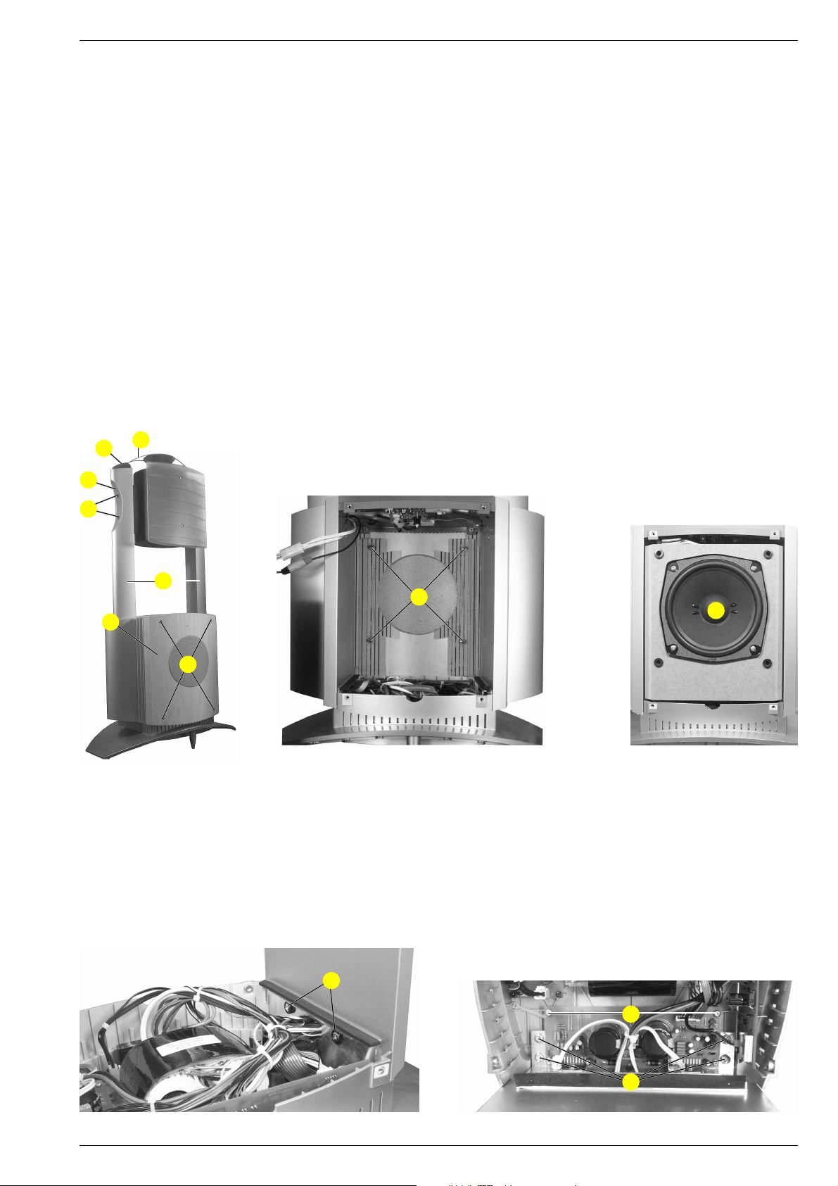
1. Lautsprechereinheit (Bassbox)
- Je 4 Schrauben A (Fig. 1) herausschrauben und die beiden
Holzblenden ∞ abnehmen. Die Lautsprechereinheit herauszie-
hen und bei Bedarf die Steckverbindungen auftrennen.
- Vor dem Wiedereinsetzen der Lautsprechereinheit die Befestigungsbolzen B (Fig. 2) von der Lautsprechereinheit abziehen
und in die Holzblenden stecken.
- In der Lautsprechereinheit sind 2 verschiedene Lautsprecher
eingebaut. Der Lautsprecher für die „Servo Control“ mit 4 Anschlüssen # (Fig. 3) hat die Materialnummer 19164 032 6100.
Der Lautsprecher mit 2 Anschlüssen hat die Materialnummer
19164 031 6100.
*
9
Disassembly Instructions
Wiring
Before disconnecting any leads and especially the earth connecting
leads observe the way they are routed to the individual assemblies.
On completion of the repairs the leads must be laid out as originally
fitted at the factory to avoid later failures or disturbances.
The given numbers correspond to the numbers in the exploded view.
To remove parts of the housing please look for the exploded view
(page 3 - 1).
1. Speaker Unit (Bass Box)
- Undo 4 screws A (Fig. 1) each and remove the 2 wooden
masks ∞ . Pull out the speaker unit and disconnect the connectors
if necessary.
- When reassembling the speaker unit pull out the fixing
bolts B (Fig. 2) from the speaker unit and insert them into the
wooden masks.
- Two different speakers are mounted in the speaker unit. The
speaker for the „Servo Control“ with 4 connectors # (Fig. 3) has
the order number 19164 032 6100. The speaker with 2 connectors
has the order number 19164 031 6100.
0
C
7
∞
A
Fig. 1
2. Mitten- / Hochtonlautsprecher %
- Je 2 Schrauben C herausschrauben und die beiden SeitenteilAbdeckungen 0 mit Kappen 9 und Bügel * nach oben aus den
Seitenteilen 7 ziehen (Fig. 1).
- Lautsprecher-Abdeckung ^ vorsichtig abnehmen.
- Der Lautsprecher kann nun abgeschraubt werden.
3. Leiterplatten
Um die Leiterplatten zu erreichen muss die Lautsprechereinheit
ausgebaut werden (Punkt 1).
Fig. 2
B
#
Fig. 3
2. Midtone Speaker / Tweeter %
- Undo 2 screws C each and pull off both side part covers 0
together with caps 9 and bracket * out of the side parts 7.
- Carefully remove the speaker cover ^ (Fig. 1).
- Now the speaker can be unscrewed.
3. Printed Circuit Boards
To get access to the PCBs the speaker unit must be removed
(para 1).
GRUNDIG Service
Fig. 4
D
F
E
Fig. 5
1 - 3
Page 4
Allgemeiner Teil / General Section
Apollo 2000
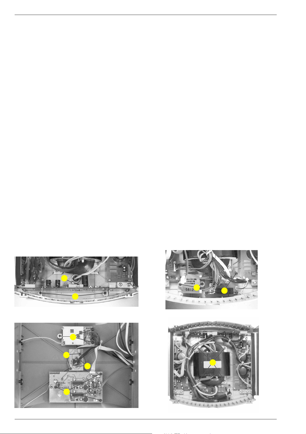
3.1 Verstärker-Platten
- Je 2 Schrauben D (Fig. 4), 4 Schrauben E (Fig. 5) und 2
Schrauben F (Fig. 5) herausschrauben.
- Steckverbinder nach Bedarf lösen.
- Kabelbinder nach Bedarf lösen.
- Verstärker-Platten mit Kühlkörper herausnehmen.
3.2 Control-Platte
- 2 Schrauben G (Fig. 6) und Schraube H (Fig. 6)
herausschrauben.
- Steckverbinder nach Bedarf lösen.
- Kabelbinder nach Bedarf lösen.
3.3 Netzanschluss-Platte
- 4 Schrauben I (Fig. 7) herausschrauben.
- Steckverbinder nach Bedarf lösen.
3.4 Audio-Funk-Modul
- 3 Schrauben K (Fig. 8) herausschrauben.
- Steckverbinder nach Bedarf lösen.
3.5 Daten-Funk-Modul
- 3 Schrauben L (Fig. 8) herausschrauben.
- Steckverbinder nach Bedarf lösen.
3.6 Netzschalter-Platte
- 2 Schrauben M (Fig. 8) herausschrauben.
- Steckverbinder nach Bedarf lösen.
4. Standby-Transformator
- Lautsprechereinheit ausbauen (Punkt 1).
- 2 Schrauben N (Fig. 7) herausschrauben.
- Steckverbinder nach Bedarf lösen.
- Kabelbinder nach Bedarf lösen.
5. Transformator
- Lautsprechereinheit ausbauen (Punkt 1).
- 4 Schrauben O am Trafo herausschrauben (Fig. 9).
- Steckverbinder nach Bedarf lösen.
- Kabelbinder nach Bedarf lösen.
6. Netzschalter
- Lautsprechereinheit ausbauen (Punkt 1).
- Schalterknopf abziehen.
- Netz-LED-Platte ausbauen (Punkt 3.6).
- 2 Schrauben P (Fig. 8) herausschrauben.
- Steckverbinder nach Bedarf lösen.
3.1 Amplifier Boards
- Undo 2 screws D (Fig. 4), 4 screws E (Fig. 5) and 2 screws F
(Fig. 5) each.
- Disconnect the connectors if necessary.
- Open the cable supports if necessary.
- Remove the amplifier boards together with the cooling plate.
3.2 Control PCB
- Undo 2 screws G (Fig. 6) and screw H (Fig. 6).
- Disconnect the connectors if necessary.
- Open the cable supports if necessary.
3.3 Mains Connecting PCB
- Undo 4 screws I (Fig. 7).
- Disconnect the connectors if necessary.
3.4 Audio RF Module
- Undo 3 screws K (Fig. 8).
- Disconnect the connectors if necessary.
3.5 Data RF Module
- Undo 3 screws L (Fig. 8).
- Disconnect the connectors if necessary.
3.6 Mains Switch PCB
- Undo 2 screws M (Fig. 8).
- Disconnect the connectors if necessary.
4. Standby Transformer
- Remove the speaker unit (para 1).
- Undo 2 screws N (Fig. 7).
- Disconnect the connectors if necessary.
- Open the cable supports if necessary.
5. Transformator
- Remove the speaker unit (para 1).
- Undo 4 screws O from the transformer (Fig. 9).
- Disconnect the connectors if necessary.
- Open the cable supports if necessary.
6. Mains Switch
- Remove the speaker unit (para 1).
- Pull off the power knob.
- Remove the mains LED PCB (para 3.6).
- Undo 2 screws P (Fig. 8).
- Disconnect the connectors if necessary.
H
N
I
G
Fig. 6
Fig. 7
L
M
P
O
K
Fig. 8
1 - 4 GRUNDIG Service
Fig. 9
Page 5
GRUNDIG Service 1 - 5
Apollo 2000 Allgemeiner Teil / General Section
Bedienhinweise Dieses Kapitel enthält Auszüge aus der Bedienungsanleitung. Weitergehende Informationen entnehmen Sie bitte der
gerätespezifischen Bedienungsanleitung, deren Materialnummer Sie in der entsprechenden Ersatzteilliste finden.
AUFSTELLEN UND SICHERHEIT
_______________________________________________
Die drahtlose Übertragungstechnik
Ihre Lautsprecher sind mit einem HF-System ausgestattet, welches das Senden
und Empfangen von Audio- und Datensignalen ermöglicht. Kabel sind nicht
mehr notwendig.
Internationale und nationale Bestimmungen schränken die HF-Übertragungsstärke ein, um störende Funksignale evtl. von Nachbarn zu vermeiden.
Die HF-Sendeleistung beträgt < 10 mW. Dies gewährleistet eine Empfangsdistanz von ca. 30 m in freiem Feld. Diese Distanz ist in Gebäuden – abhängig
vom verwendeten Baumaterial – eingeschränkt.
Vermeiden Sie einen Aufstellungsort in der Nähe von metallischen Materialien
(z.B. Heizkörper) sowie nahe an elektrischen Geräten, die auf Funk basieren
(z.B schnurlose Telefone).
Da es sich bei der Funkübertragung der Audio- und Datensignalen um keinen
exklusiven Übertragungsweg handelt, ist es nicht auszuschließen, dass es hierbei zu Störungen kommen kann. Um diese Störungen zu vermeiden, könne Sie
den Übertragungskanal des Audiosignals verändern.
Unter Umständen können Personen, Wände oder andere Oberflächen die Funksignale reflektieren. Reflektierte Signale vermischt mit direkten (nicht reflektierten) Signalen können Signalstörungen verursachen, Mehrwegeempfang
genannt. Dies kann zu Rauschen oder kurzzeitigem Tonausfall führen. Tritt eine
solche Störung auf, genügt es, die Lautsprecherboxen anders zu positionieren.
AUFSTELLEN UND SICHERHEIT
____________________
Damit diese hochwertigen und komfortablen Lautsprecher Ihnen lange Zeit Freude und Unterhaltung bereitet, beachten Sie beim Aufstellen der Lautsprecher
bitte die folgenden Hinweise:
Diese Lautsprecher sind für die Wiedergabe von Tonsignalen bestimmt.
Jede andere Verwendung ist ausdrücklich ausgeschlossen.
Zum Transportieren der Lautsprecher fassen Sie die Lautsprecher nur an den
seitlichen Aluminiumprofilen an.
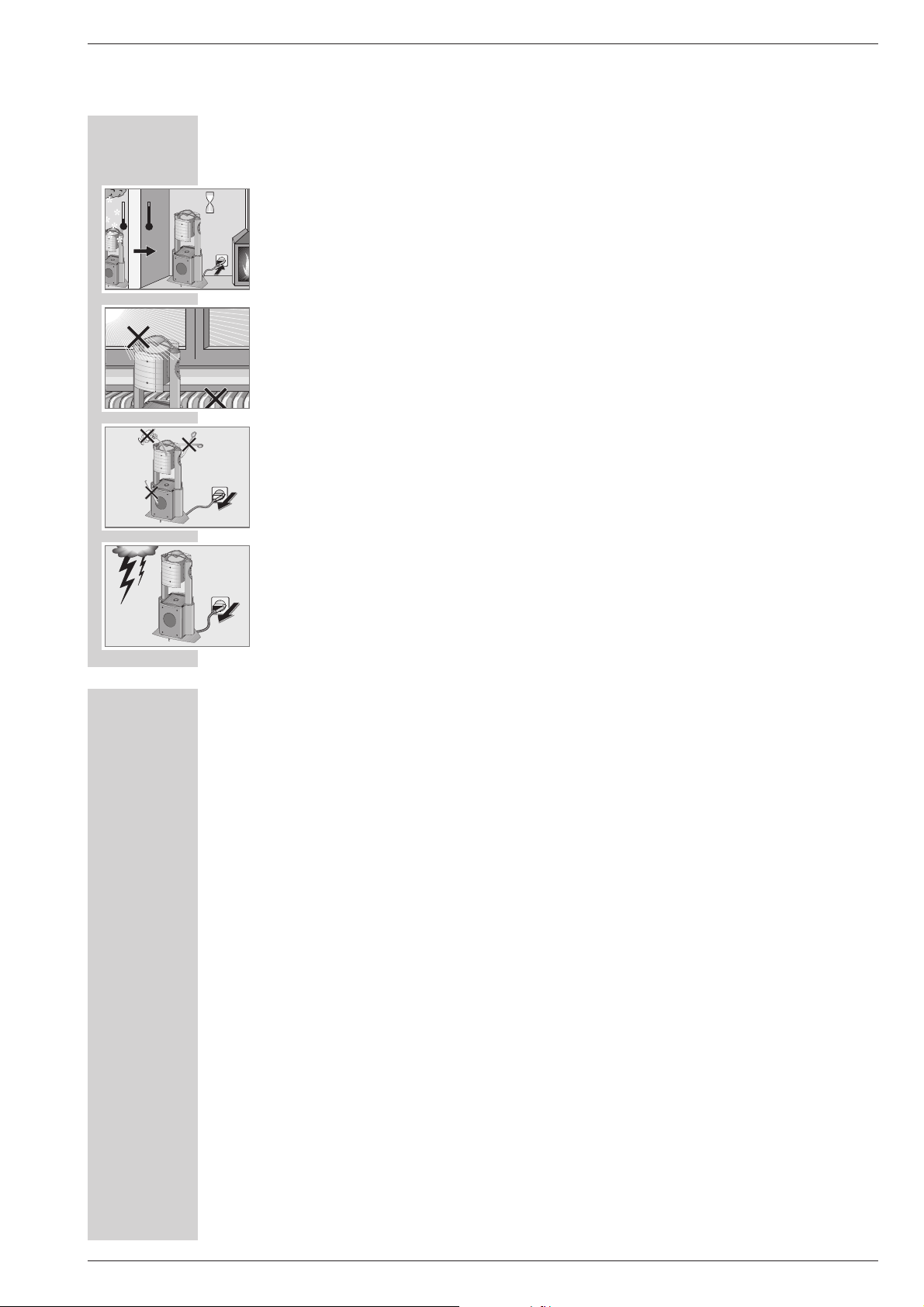
Wenn die Lautsprecher starken Temperaturschwankungen ausgesetzt sind,
zum Beispiel beim Transport vom Kalten ins Warme, schließen Sie sie an das
Stromnetz an und lassen sie mindestens zwei Stunden stehen.
Die Lautsprecher sind für den Betrieb in trockenen Räumen bestimmt. Sollten Sie
sie dennoch im Freien betreiben, sorgen Sie unbedingt dafür, dass sie vor
Feuchtigkeit (Spritz- und Tropfwasser) geschützt sind.
Stellen Sie die Lautsprecher nicht in unmittelbare Nähe der Heizung oder in die
pralle Sonne, dadurch wird die Kühlung beeinträchtigt.
Sie dürfen die Lautsprecher auf keinen Fall öffnen. Für Schäden, die durch
unsachgemäße Eingriffe entstehen, übernimmt der Hersteller keine Garantie.
Gewitter stellen eine Gefahr für jedes elektrische Gerät dar. Auch wenn die Lautsprecher ausgeschaltet sind, können sie durch einen Blitzschlag in das Stromnetz beschädigt werden. Bei einem Gewitter müssen Sie immer die Netzstecker
ziehen.
°C
2h
°C
1
P
O
W
E
R
1
PO
W
ER
! SERVICE !! SERVICE !! SERVICE !
P
O
W
E
R
1
P
O
W
E
R
1
Page 6

1 - 6 GRUNDIG Service
Allgemeiner Teil / General Section Apollo 2000
Anschließen
Netzkabel anschließen
1 »Stecker des Netzkabels in die Steckdose stecken.
Hinweis:
Wie Sie die Lautsprecher an Ihrer HiFi-Anlage installieren, entnehmen Sie
bitte der Bedienungsanleitung der HiFi-Anlage.
In dieser Bedienungsanleitung ist auch beschrieben, wie Sie – wenn mehrere
Lautsprecherpaare im Gebrauch sind – die Lautsprecherpaare verschiedenen Räumen zuordnen können.
Lautsprecherkabel anschließen (wenn gewünscht)
1 Buchsen »L PREAMP OUT R« der HiFi-Anlage mit einkanaligem abge-
schirmten Lautsprecherkabel an die Buchsen »LINE IN« der Lautsprechers
anschließen.
Einschalten und Betrieb
1 Beide Lautsprecher mit »POWER« einschalten.
– Die Anzeigen leuchten rot.
2 HiFi-Anlage einschalten.
Hinweise:
Die Lautsprecher schalten sich automatisch ein bzw. aus, wenn die HiFiAnlage ein-/ oder ausgeschaltet wird, die Anzeigen der Lautsprecher leuchten grün.
Sind die Lautsprecher mittels NF-Kabel mit der HiFi-Anlage verbunden,
werden sie eingeschaltet, wenn ein Audiosignal an den Buchsen »LINE IN«
anliegt.
Wird kein Tonsignal gesendet, schalten sich die Lautsprecher nach kurzer
Zeit (ca. 1-2 Minuten) automatisch ab, die Anzeigen der Lautsprecher leuchten rot.
ANSCHLIESSEN UND BETRIEB
______________________
Die Bedienelemente und Anschlüsse
POWER Schaltet den Lautsprecher ein und wieder aus.
Der Lautsprecher ist vollständig vom Netz getrennt.
Anzeigen Im Netzschalter:
rot: Lautsprecher in Bereitschaft (Stand-by);
grün: Lautsprecher in Betrieb;
orange: Lautsprecher im Installations-Betrieb;
grün und orange blinken: Reset Mode;
rot blinkt: die Schutzschaltung hat angesprochen.
Reset Im Gehäuseboden; Taster zum Zurücksetzen in den
Auslieferungszustand.
ÜÜ
Netzkabel.
LINE IN Im Gehäuseboden; Tonsignaleingang.
Für Sonderanwendungen oder wenn Ihre HiFiAnlage mittels Kabel an die Lautsprecher (nur
Raum 1) angeschlossen werden soll.
Hinweis:
Wenn die Schutzschaltung angesprochen hat,
schalten Sie den Lautsprecher mit »POWER« aus
und lassen ihn mindestens 15 Minuten abkühlen.
AUF EINEN BLICK
_____________________________________________________
LINE IN
RESET
POWER
POWER
1
POWER
1
POWER
1
Page 7

GRUNDIG Service 1 - 7
Apollo 2000 Allgemeiner Teil / General Section
Operating Hints This chapter contains excerpts from the operating instructions. For further particulars please refer to the appropriate
user instructions the part number of which is indicated in the relevant spare parts list.
SET-UP AND SAFETY
_________________________________________________________________
The wireless transmission system
Your loudspeakers are equipped with an HF system which enables them to transmit and receive audio and data signals without the need for cables.
The HF transmission strength is limited by national and international regulations
to prevent radio interference from neighbouring devices.
The HF transmission power is
<
10 mW. This guarantees an unhindered reception range of approximately 30 m. This range is restricted inside buildings,
depending on the construction materials used.
Avoid placing the loudspeakers near metal objects such as radiators or electrical devices such as cordless telephones which use radio signals.
Since the audio and data signals are not transmitted on an exclusive range we
cannot guarantee that this will not cause interference. To avoid interference you
can change the communication channel for the audio signal.
In some circumstances, people, walls and other surfaces can reflect radio signals. Reflected signals can mix with direct (non-reflected) signals thus causing a
type of interference known as multi-path reception. This can lead to noise or a
temporary loss of sound. If such interference does occur, simply position the
loudspeakers differently.
SET-UP AND SAFETY
______________________________________________
To ensure that these high-quality, easy-to-use loudspeakers provide you with
lasting enjoyment, please observe the following instructions when setting them
up.
These loudspeakers are designed for the playback of audio signals.
Any other use is expressly prohibited.
When transporting the loudspeakers only pick them up using the aluminium frames on the sides.
If the loudspeakers are subjected to sudden changes in temperature, for example if they are brought in from the cold to a warm room, connect them to the
mains supply and let them stand for at least two hours.
The loudspeakers are designed for use in dry rooms. If you do use them in the
open, please ensure that they are protected from moisture, such as rain or lawn
sprinklers.
Do not place the loudspeakers close to heating units or in direct sunlight, as this
will impair cooling.
Do not open the loudspeaker casing under any circumstances. The manufacturer
accepts no liability for damage resulting from improper handling.
Thunderstorms present a danger to all electrical devices. Even if the loudspeakers are switched off, they can be damaged by a lightning strike to the
mains. Always remove the mains plug in the event of an electrical storm.
°C
2h
°C
1
P
O
W
E
R
1
PO
W
ER
! SERVICE !! SERVICE !! SERVICE !
P
O
W
E
R
1
P
O
W
E
R
1
Page 8

1 - 8 GRUNDIG Service
Allgemeiner Teil / General Section Apollo 2000
Controls and connections
POWER Switches the loudspeaker on and off again.
The loudspeaker is completely disconnected from the
mains.
Indicators In the mains button:
Red: the loudspeaker is in Stand-by mode;
Green: the loudspeaker is in operation;
Orange: the loudspeaker is in Installation mode;
Flashing green and orange: Reset mode;
Flashing red: the protective circuit has been actuated.
Reset Button located on the bottom of the casing to reset
the loudspeaker to its original state.
ÜÜ
Mains cable.
LINE IN Audio signal input on the bottom of the casing.
For special applications or if you want to connect
your HiFi system to the loudspeakers using a cable
(Room 1 only).
Note:
If the protection circuit is actuated, switch off the
loudspeaker using the »POWER« button and let it
cool down for at least 15 minutes.
OVERVIEW
________________________________________________________________________
LINE IN
RESET
POWER
Connection
Connecting the mains cable
1 Plug the mains cable into the socket.
Note:
To install the loudspeakers on your HiFi, see the Instruction Manual of the
HiFi System.
This manual also describes how to assign pairs of loudspeakers to different
rooms, if you are using more than one pair.
Connecting loudspeakers cables (if required)
1 Connect the »L PREAMP OUT R« sockets on the HiFi System to the
»LINE IN« sockets on the loudspeakers using single-channel shielded loudspeaker cables.
Switching on and using the loudspeakers
1 Switch on both loudspeakers using the »POWER« button.
– The red indicators light up.
2 Switch on the HiFi.
Note:
The loudspeakers switch themselves on or off automatically when you switch
the HiFi on or off. The green indicators in the loudspeakers light up.
If the loudspeakers are connected to the HiFi with LF cables, then they are
switched on when an audio signal is received at the »LINE IN« sockets.
If no audio signal is sent, the loudspeakers switch themselves off after a short
period (approx. 1-2 minutes) and the red indicators on the loudspeakers
light up.
CONNECTION AND OPERATION
_____________
POWER
1
POWER
1
POWER
1
Page 9

Apollo 2000 Schaltpläne und Druckplattenabbildungen / Circuit Diagrams and Layout of PCBs Apollo 2000 Schaltpläne und Druckplattenabbildungen / Circuit Diagrams and Layout of PCBs
Schaltpläne und Druckplattenabbildungen / Circuit Diagrams and Layout of PCBs
Verdrahtungsplan / Wiring Diagram
MIDTONE
SPEAKER-B
15
14
2
1
2
1
12
11
DATEN-FUNK-MODUL
DATA RF MODULE
NF-VERSTÄRKER
POWER AMP #1
P3C
P6C
15
1
3
CONTROL-PLATTE
CONTROL BOARD
SI421
11
1
P4C
P7C
P8C
SI302 SI301
P10C
1
BU301
91
P9C
P12C
91
21
P13C
8
8
1
P5C
9
2
NETZSCHALTER-PLATTE
3 259
MAINS SWITCH BOARD
P10
13
5 2 2
NF-VERSTÄRKER
POWER AMP #2
1
P01
9
1
2
14
15
SUBWOOFER
SPEAKER-A
15
14
2
1
TRAFO
SPEAKER-A
AUDIO-FUNK-MODUL
SUBWOOFER
AUDIO RF MODULE
33
P01
9
TRAFO
1
STAND-BY
TRAFO
NETZSCHALTER
NETZ
F01
SI01
2
P02
SI02
NETZ-ANSCHLUSS-PLATTE
2
MAINS CON BOARD
P03
SWITCH
2
1
P01
MAINS SWITCH
TRAFO
1
2
14
15
SPEAKER-B
TWEETER
GRUNDIG Service GRUNDIG Service
2 - 22 - 1
Page 10

Schaltpläne und Druckplattenabbildungen / Circuit Diagrams and Layout of PCBs Apollo 2000 Schaltpläne und Druckplattenabbildungen / Circuit Diagrams and Layout of PCBs Apollo 2000
Control-Platte / Control Board
70
60
50
40
30
20
10
0
Y
X
Bauteil /
Component
XY
BU301 105 2
C209 115 6
C210 118 18
C261 137 26
C262 143 34
C263 132 31
C266 133 26
C267 135 26
C268 153 18
C269 153 20
C270 152 15
P17C
81
P5C
C271 153 16
C272 139 7
C273 142 6
C277 148 7
C278 134 22
C282 144 9
C284 126 7
C285 129 4
C291 63 47
C292 86 49
C293 86 40
C294 99 49
C295 93 49
C296 94 49
P3C
13
13
R392
T393
R398
R397
IC391
R491
R492
R493
SW392
59472-314.00(05)4B
APOLLO CONTROL BOARD
C297 97 49
C303 60 57
C309 171 57
C310 148 56
C311 121 60
C312 121 50
C313 160 45
C314 142 45
C315 172 6
C316 172 13
C317 147 51
C318 165 51
C319 187 15
C320 187 18
R391
T392
R396
R395
P6C
R283
C391
R471
R482
R484
R472
C321 157 38
C322 155 33
C323 156 29
C349 177 20
C350 177 18
C361 167 6
C362 157 9
C363 161 6
C364 163 20
C365 163 23
C366 153 23
C371 176 33
C372 173 28
C373 167 28
15
R488 R487
T496
T431
R433
T493
R489
R485
T495
C374 187 32
C375 187 29
C376 187 36
C388 66 38
C389 57 37
C391 32 48
C400 123 31
C401 115 33
C402 127 26
C406 111 23
C407 122 26
C409 107 30
C410 107 27
C411 101 27
C426
D433
IC392
T494
R483
R458
R400
T492
R432
T432
R431
R434
Q391
-+
R302
C631
C389
R630
R631
C630
D441
R459
R481
R486
R490
T491
C426 50 50
C451 152 42
C471 133 17
C472 135 7
C473 125 19
C474 120 4
C475 132 13
C476 119 11
C630 62 28
C631 59 37
C922 74 40
C3011 172 36
C3012 172 32
C3013 161 33
C303
R304
C291
C388
R632
D442
R442
R441
D303
T302
R445
D300
~~
D302
R303
C922
-+
-+
T630
D630
R389
IC206
R443
15
P16C
C3030 155 25
C3031 158 13
C3032 158 16
C3511 159 13
C3512 159 16
C3521 179 35
C3522 183 35
D291 86 57
D300 75 53
D302 66 54
D303 66 58
D310 110 61
D311 127 55
D331 97 44
-+
C292
D291
~~
-+
+
1
SI421
T200mA-L
D332 100 44
D411 104 31
D412 102 31
D433 48 49
D441 59 20
D442 61 20
D451 151 37
D452 151 40
D630 66 30
IC203 144 20
IC206 75 28
IC301 168 33
IC303 176 10
IC304 185 10
C295
IC421
R394
P7C
C296
C293
BU301
R393
P4C
C294
C297
D332
D331
D412
R412
C411
IC305 195 10
IC306 195 20
IC315 160 56
IC316 139 55
IC351 164 14
IC352 181 31
IC391 31 44
IC392 49 34
IC401 115 27
IC402 127 12
IC421 86 28
P03C 24 61
P04C 102 54
D310
T391
21
SI303
C409
R411
D411
R409
R410
C410
C406
R408
P10C
P8C
C312
SI302 SI301
C401
R402
IC401
R474
C210
R210
21
C476
R209
C209
R473
P05C 7 37
P06C 35 61
P07C 95 55
P08C 113 55
P09C 195 59
P10C 113 15
P12C 195 41
P13C 196 30
P16C 77 9
P17C 14 61
Q391 58 43
R209 115 9
R210 116 19
C311
T315mA-LT315mA-LT315mA-L
C400
-+
R407
C407
-+
R478 R477
-+
R476
C284
-+
C474
D311
-+
~~
R451
C263
-+
R401
R405
R406
R404
C402
C278
C473
IC402
-+
R284
C285
R285
R261 137 30
R271 152 10
R272 152 12
R273 149 32
R274 151 32
R281 139 5
R282 144 6
R283 36 57
R284 125 5
R285 125 4
R302 63 49
R303 67 52
R304 63 52
R306 169 6
IC316
C314
C262
C267
C266
-+
-+
C475
R475
C472
+
R261
C261
+
C471
14 1
-+
C272
R281
R307 180 5
R308 185 5
R309 189 5
R310 195 5
R311 191 9
R313 189 9
R314 189 12
R315 182 13
R316 182 10
R317 184 20
R318 180 20
R319 186 20
R320 188 20
R321 159 28
R382
C376
R376
C374
R320
C320
R341
C319
IC304
R309
P9C
R375
R353
R351
IC203
C273
D451
R282
IC315
C310
-+
C317
CHASSIS
C451
D452
R453
R274
-
R273
R325
2815
R454
C366
C282
C269
C268
-+
C271
C277
C270
R272
R271
C322
R323
C3030
C3032
+
C321
C323
R364
R366
C3031
C362
R361
R452
R322
C309
C318
C313
R324
IC301
C3013
-+
R321
C365
C3511
C363
C373
C3512
R362
R3031
R371
R365
IC351
C361
C372
C364
C349
C350
R363
IC303
R306
R349
C316
-+
C3011
C3012
C315
C371
R372
R347
R345
R463
R315
R373
R344R343
R342
R346
R461
R462
T461
C3521
IC352
R350
R316
R307
91
R384
91
C3522
C375
R374
R348
R319
R318
R317
R308
1501401301201101009080706050403020100 160 170 180 190 200 210
R322 159 26
R323 156 36
R324 169 38
R325 156 31
R341 183 18
R342 180 18
R343 177 23
R344 180 23
R345 180 13
R346 180 10
R347 177 22
R348 180 22
R349 177 16
R350 180 16
R351 190 18
R352 195 15
R353 196 27
R361 159 9
R362 162 9
R363 167 15
R364 160 20
R365 166 21
R366 158 20
R371 169 27
R372 175 29
R373 176 36
R374 187 27
R375 189 30
R376 187 34
R381 198 47
R382 190 47
R383 198 45
R384 190 45
R389 68 27
R391 26 56
R392 21 56
R393 100 61
R394 96 61
R395 25 48
R396 25 49
R397 21 48
R398 21 49
R400 52 20
R401 123 29
R402 109 30
R404 130 26
R405 124 26
R406 125 26
R407 120 26
R408 103 27
R409 105 27
R410 108 27
R411 107 33
R412 100 27
R431 53 54
R432 53 58
R433 46 44
R381
R383
21
P13C
IC306
R352
IC305
R310
P12C
R314
R313
R311
R434 52 50
R441 61 16
R442 63 16
R443 65 21
R444 62 25
R445 64 25
R451 132 38
R452 157 33
R453 153 33
R454 156 28
R458 53 20
R459 54 20
R461 182 58
R462 182 56
R463 179 56
R471 28 30
R472 28 25
R473 115 4
R474 120 18
R475 132 11
R476 120 8
R477 122 15
R478 119 15
R481 54 18
R482 28 28
R483 51 18
R484 28 26
R485 48 10
R486 59 15
R487 47 13
R488 44 13
R489 44 10
R490 59 14
R491 28 20
R492 28 19
R493 28 17
R630 59 33
R631 62 30
R632 61 37
R3031 165 6
SI301 125 44
SI302 116 44
SI303 106 44
SI421 85 20
SW392 24 4
T302 67 48
T391 103 61
T392 25 53
T393 21 53
T431 48 56
T432 56 58
T461 182 53
T491 54 10
T492 54 15
T493 45 22
T494 45 18
T495 49 7
T496 44 7
T630 61 33
NF-Verstärker-Platte
Power Amplifier Board
R28
R21
C29
T28
T29
C24
+
E
E
IC01
C23
C
C
+
C12
R24
R29
R13
C13
R31
R12
+
C15
C11
+
R11
P01
+
+
C14
R14
R111
C21
R15
BR15
C22
C26
C25
D16
C09
SPEAKER-A
R25
C111
+
R16
91
BR16
D02
THP01
C04
C03
D01 D04
C27
BR14
SI01
BR11
BR21
T4A-LT4A-L
SI02
TRAFO
+
BR22
BR23
BR13
BR12
C06
59452-302.00(02)4B
GRUNDIG Service GRUNDIG Service
2 - 42 - 3
C124
D03
R124
R121
+
C05
POWERAMP
IC101
+
C123
R128
BR31
R112
R113
BR32
+
BR33
C115
BR34
BR17
C114
+
C113
C112
+
C121
BR36
BR35
SPEAKER-B
C122
R115
C126
R114
C127
R125
C125
R116
D116
Page 11

Apollo 2000 Schaltpläne und Druckplattenabbildungen / Circuit Diagrams and Layout of PCBs Apollo 2000 Schaltpläne und Druckplattenabbildungen / Circuit Diagrams and Layout of PCBs
NF-Verstärker-Platte / Power Amplifier Board
+30V
+B
OPTION-A
F
C03
0.1U/50V/10%
F
C04
0.1U/50V/10%
CHASSIS
22V~
22V~
SI01
T4A-L
SI02
T4A-L
3
FROM
2
POWER
1
TRANSFORMER
TRAFO
Seite / page
2 - 10
85C
THP01
C09
-30V
+
C05
+
C06
D03
1N5401
6800U/50V
D01
1N5401
6800U/50V
D04
D02
1N5401
1N5401
HEAT
10N
K
+30V
13 7 5 11 12
R24
22k
IC01
TDA7294
+B
+VS+PVS
0.1U/50V/10%
F
C21
-B
LS
SPEAKER-A
2
1
C27
K
22N
+
C29
100U/25V
CHASSIS
R29
47k
R28
22k
C24
R21
K
47p/5%
C23
R25
4.7R
F
C25
0.1U/50V/10%
F
C26
0.1U/50V/10%
DC PROTECTION
T28
BC546B
+
22k
22U/50V
0V
14
0V
6
T29
BC546B
OUT
BOOTSTRAP
S/C
PROTECTION
R31
0R
THERMAL
SHUTDOWN
-PVS -VS STBY-
-30V
0.1U/50V/10%
+B
-B
F
C22
0.1U/50V/10%
F
C121
MUTE
STBY
1815
IN-
IN+
MUTE
STBY
0V
2
0V
3
4
10
9
10U/25V
5V3
5V3
22k
R15
4.7k
R14
C13
+
47U/25V
R12
22k
C12
K
33k
R16
1N4148
D16
220p/5%
1U/50V
C11
R11
+
1k
DC-PROT
HEAT
STBY-AMP
5V
0V
5V3
P01
1
2
3
4
5
6
7
8
9
2 - 7
Seite / page
TO P9C / P12C CONTROL BOARD
680R
R13
+
+
C15
C14
10U/25V
IC101
0V
14
0V
6
TDA7294
OUT
BOOTSTRAP
S/C
PROTECTION
-PVS -VS STBY-
R124
C124
K
R125
22k
47p/5%
C123
4.7R
F
C125
0.1U/50V/10%
F
C126
0.1U/50V/10%
R121
+
22k
22U/50V
LS
SPEAKER-B
22k
R128
2
1
C127
K
22N
CHASSIS
GRUNDIG Service GRUNDIG Service
+30V
13 7 5 11 12
+VS+PVS
THERMAL
SHUTDOWN
-30V
F
C122
0.1U/50V/10%
MUTE
STBY
1815
-B
-B
IN-
IN+
MUTE
STBY
0V
2
680R
R113
C113
+
47U/25V
0V
3
4
10
9
10U/25V
5V3
5V3
+
C115
+
10U/25V
C114
22k
R115
4.7k
R114
R112
22k
C112
1N4148
2 - 5 2 - 6
K
33k
R116
D116
220p/5%
1U/50V
C111
+
R111
1k
Alle Spannungsangaben sind Näherungswerte
All voltage levels are approximates
13.10.99
Page 12

Schaltpläne und Druckplattenabbildungen / Circuit Diagrams and Layout of PCBs Apollo 2000 Schaltpläne und Druckplattenabbildungen / Circuit Diagrams and Layout of PCBs Apollo 2000
5.6k
R431
LL4148
D432
1k
R432
100N/5%
C272
P12C
BC8
T43
3.3k
R412
4.7N/5%
C320
LL4148
D412
LL4148
D411
3.3k
R411
100N/5%
C411
3.3k
R408
3.3k
R409
220k
R410
100p
C410
22N
C631
1k
R404
220k
R407
220N
C409
3.3k
R405
3.3k
R406
-
+
LM833D
IC401B
LL4148
D630
10K
R631
BC848B
T630
+
47U/6.3V
C388
47n
C389
47R
R389
3.6864MHz
Q391
100N/5%
C400
47k
R398
10k
R397
BC858
T393
220N
C630
P9C
330N/5%
C365
100k
R632
10k
R352
10k
R351
-
+
LM833D
IC351B
47N/5%
C349
10k
R366
BU301
470N/5%
C406
470N/5%
C402
82k
R364
5.6k
R365
-
+
LM833D
IC351A
100N/5%
C3031
100N/5%
C3032
15k
R361
15k
R362
15k
R363
100p
C407
100k
R630
-
+
LM833D
IC301B
47p
C209
22p
C210
1k
R209
20k
R210
6.8k
R323
47k
R324
1.8n
C322
1.8n
C323
47p
C284
27n
C373
8.2k
R325
180K
R313
13K
R311
6.8K
R314
-
+
LM833D
IC304
330K
R320
10k
R321
68K
R319
10N/5%
C319
N.C.
C350
22k
R315
6.8K
R316
1M
R318
1M
R317
470K
R341
4.7K
R342
4.7K
R348
10k
R384
82K
R347
10k
R309
330N/5%
C364
10k
R307
27K
R345
-
+
LM833D
IC305B
1.5K
R346
680K
R344
150k
R343
100N/5%
C3512
750K
R349
1M
R350
5.6k
R383
-
+
LM833D
IC303A
330N/5%
C273
22N/5%
C282
-
+
LM833D
IC306B
10k
R310
3.9k
R381
-
+
LM833D
IC352A
100N/5%
C361
10N/5%
C362
39k
R371
27n
C372
27n
C371
5.6n
C376
100n
C426
100k
R373
10k
R372
-
+
LM833D
IC352B
3.3k
R322
18k
R376
18k
R375
18k
R374
330N/5%
C363
P13C
100k
R353
+
2.2U/25V
C278
+
2.2U/25V
C277
12k
R271
-
+
LM833D
IC301A
1.8n
C321
100N/5%
C3511
270p
C375
270p
C374
3
-
+
LM833D
IC306A
5.6k
R272
220R
R281
3.3k
R282
-
+
LM833D
IC305A
22n
C261
+
100U/16V
C262
0R
R261
22k
R306
+
22U/16V
C263
P10C
-
+
LM833D
IC401A
1k
R274
1k
R273
10k
R308
-
+
LM833D
IC303B
-
+
LM833D
IC304B
I 2 C2627
28
16
6
812191821204
212325131415
53222491011
7
17
U
MUTE
TDA7313D
IC203
100N/5%
C271
100N/5%
C270
47N/5%
C269
1U/5%
C268
1.8N/5%
C267
1.8N/5%
C266
100N/5%
C3012
100N/5%
C3522
100N/5%
C3521
100N/5%
C3011
1k
R453
1K
R451
LL4148
D451
4.7C
D452
10k
R458
100k
R445
100k
R444
100k
R452
T200mA-L
SI421
100N/5%
C451
10k
R400
10k
R459
BSP60
T431
330N/5%
C366
+
1U/50V
C473
+
1U/50V
C474
+
4.7U/25V
C285
-
+
LM833D
IC402A
-
+
LM833D
IC402B
100k
R473
43k
R474
100k
R476
4.7k
R475
6.8k
R285
47k
R284
100k
R477
4.7k
R478
+
22U/16V
C471
+
22U/16V
C472
1UF
C3030
+
22U/16V
C476
100N/5%
C475
12K
R3031
0R
R382
DC-PROT1
DC-PROT1
NF-DET
INSEL
NF-SENSE
NF-SENSE
+D
+D
LINE-IN
TWEET
WOOFER-OUT
WOOFER
WOOFER-OUT
+A
+A
MID
-E
-E
-E
-E
-E
-E
-E
+5V
+5V
+5V
LIMITER
TWEETER-OUT
+E
+E
+E
+E
+E
+E
+E
CHANNEL
KEY0
+RX
MID-OUT
HEAT-PROT
DC-PROT2
DC-PROT2
3.3k
R402
3.3k
R401
+
22U/16V
C401
V2
+5V
LIMITER
STBY-AMP
SUBSONIC
HIGH-PASS FILTER
Fg ≈ 32Hz
TO AUDIO
RF MODULE
LOW LEVEL DETECTION
TO SUBSONO
SENSOR
TO P01
POWER AMP BOARD #2
TO P01
POWER AMP BOARD #1
SUBSONO
LOW-PASS FILTER
LOW-PASS FILTER
HIGH-PASS FILTER
HIGH-PASS FILTER
LINE
IN
3.3k
R461
+D
STBY-AMP
10K
R454
4.7k
R441
4.7k
R442
100k
R443
1N4148
D442
1N4148
D441
+5V
HEAT1
HEAT2
HEAT-PROT
9
8
7
6
5
4
3
2
1
7
6
5
9
8
7
6
5
4
3
2
1
7
6
5
1
2
1
2
3
4
8
7
6
5
8
1
2
3
4
8
7
6
5
1
2
3
7
6
5
1
2
3
7
6
5
4
8
2
1
1
2
3
4
1
2
3
4
8
1
2
3
4
8
2
1
1
2
3
4
8
7
6
5
4
8
7
6
5
1
2
3
4
8
7
6
5
+D
9V2
4V7
4V7
4V7
4V7 4V7 4V7 4V7 4V7 4V7 4V7 4V7 4V7 4V7
4V7
4V7
5V
5V
9V2
9V
9V2
9V2
4V7
4V7
4V7
4V7
0V
0V 0V
0V
0V
0V
0V
0V
0V
0V
0V
0V
0V
0V
0V
0V
0V
0V
-12V
+12V
0V
0V
0V
0V
0V
0V
0V
0V
0V
0V
2V5
2V5
2V5
2V5
2V5
2V5
2V5
5V
5V
0V
5V
0V
5V
5V3
-12V
+12V
-12V
+12V
-12V
+12V
-12V
+12V
-12V
+12V
-12V
+12V
Control-Platte / Control Board
Seite / page
Seite / page
2 - 6
2 - 6
GRUNDIG Service GRUNDIG Service2 - 7 2 - 8
Page 13

Apollo 2000 Schaltpläne und Druckplattenabbildungen / Circuit Diagrams and Layout of PCBs
R398
P5C
WAKEUP
1
2
RTS
3
R283
+5V
+RX
TRX-ON
RX-MUTE
47k
RXD
CTS
TXD
RX-SDA
RX-SCL
4
5
6
7
TO DATA RF MODULE
8
P6C
1
2
3
4
5
TO AUDIO RF MODULE
DET
T-PROT
ITER
3.6864MHz
Q391
1
P12/SCLK
2
P13/SDATA
3
P20/CNTR0
4
P20/AN0
5
P21/AN1
6
P22/AN2
7
P23/AN3
8
P24/AN4
9
P25/AN5
10
P26/AN6
IC392
11
12
13
14
15
16
17
18
P27/AN7
VREF
/RESET
CNVss
Vcc
Xin
Xout
M37531M4-XXXFP
P36/LED6/INT1
CONTROLLER
P11/TxD
P10/RxD
P37/INT0
P35/LED5
P34/LED4
P33/LED3
P32/LED2
P31/LED1
P30/LED0Vss
P07
P06
P05
P04
P03
P02
P01
P00
36
35
34
33
32
31
30
29
28
27
26
25
STBYPOWERAMP
24
23
22
21
20
19
RX-ON
PD
6.8k
R481
6.8k
R482
R471
6.8k
R394
R472
10k
10k
R483
150k
SW392
INITIAL-SET
SDA
SCL
R484
IC391
X24C04
5
6
+5V
10k
SDA
SCL
R490
220k
R486
BC848B
T492
8
VCC
TEST
VSSA2A1A0
1234
47k
10k
T491
BC848B
7
47n
R493
+5V
R487
C391
220k
T493
BC848B
R488
47k
10k
T494
BC848B
R491
R485
220k
BC848B
T495
R489
47k
10k
T496
BC848B
R492
-AMP
D432
L4148
1k
R432
SI421
00mA-L
47k
+D
R397
10k
9V2
3.3k
T432
BC848B
BC858
T392
R461
4.7k
R462
T461
BC848B
L4892CV
OUT IN
3
IC421
GND
2
D433
R434
R396
47k
R463
R433
22k
LL4148
22k
1
47k
R395
10k
STBY-POWERAMP
RX-ON
+12V
+12V
+5V
47k
R393
RELAIS DRIVE
LL4148
D332
T391
BC848B
R391
390R
R392
390R
+5V
C292
C293
18k
+
2200U/25V
+
C314
0.1U/63V
+
C313
0.1U/63V
47k
R303
22n
22n
470U/25V
D311
DF02S
470U/25V
1U/50V
C294
C297
+
T302
BC848B
PD
R302
IC206
L7805CD2T
OUT IN
3
+
C922
100n
+
10U/16V
C310
C291
C315
10U/16V
D310
1N4001
+12V
+E
GND
2
L78M12CDT
OUT IN
3
0.1U/50V
IC316
GND
2
1
100n/63V
+17V
1
C317
+
C3013
22U/35V
+
C309
C316
10U/16V
-E
-12V
0.1U/50V
3
OUT
L7912CD2T
C318
1
GND
2
IN
-17V
IC315
Alle Spannungsangaben sind Näherungswerte
All voltage levels are approximates
+
D291
DF02S
~
~
C303
R304
+
-
1N4001
1N4001
12k
-
D302
D303
~
22n
22n
C312
C311
C295
C296
SI302
T315mA-L
0.1U/63V
0.1U/63V
SI301
T315mA-L
D300
DF02S
~
14V~
14V~
LL4148
D331
14V~
+
+12V
P4C
1
2
TO P01
BOARD
MAINS CON
2 - 10
Seite / page
3
2
1
1
2
TO P10
P3C
MAINS SWITCH
P7C
FROM
STANDBY
TRANSFORMER
BOARD
Seite / page
2 - 10
Seite / page
2 - 10
~
SI303
T315mA-L
5
4
FROM
3
POWER
2
TRANSFORMER
1
Seite / page
P8C~
2 - 10
23.03.00
GRUNDIG Service 2 - 9
Page 14

Schaltpläne und Druckplattenabbildungen / Circuit Diagrams and Layout of PCBs Apollo 2000
Netzteil / Power Supply
gb
22V~
22V~
22V~
22V~
14V~
14V~
rt
gb
bl
sw
bl
gr
gr
bn
wh
bn
BOARD #1
TO POWER AMP
Seite / page
BOARD #2
TO POWER AMP
Seite / page
TO P8C
CONTROL BOARD
Seite / page
TO P4C
2 - 9
Seite / page
MAINS
230V AC
50-60Hz
P01
+12V
1
2
STDBY
CONTROL BOARD
BN
2
1
NETZ
BL
L-115WEGWLED10
3.3n/20%/400V
K
C01
F01
1
23
4
SW2
SW1
1
SWITCH
L-115WEGWLED11
Th.sw.
110°C
R01
G2R-1/12VDC
54
SI01
T2.5A-L
SI02
T315mA-L
STR1
2
STR2
1
2
P02
32 1
3.3n/20%/400V
K
C02
NETZANSCHLUSSPLATTE
MAINS CON BOARD
Th.sw.
102
°C
11V~
PTR2
PTR1
2
1
29.09.99
P03
TO P7C CONTROL BOARD
POWER TRANSFORMER
Seite / page
2 - 9
STANDBY
TRANSFORMER
2 - 6
2 - 6
2 - 9
MAINS SWITCH
NETZSCHALTERPLATTE
MAINS SWITCH BOARD
12.10.99
31
P10
TO P3C
CONTROL BOARD
Alle Spannungsangaben sind Näherungswerte
All voltage levels are approximates
Seite / page
2 - 9
Netzanschluß-Platte / Mains Con Board Netzschalter-Platte
Mains Switch Board
59452-304.00(02)4B
P01
21
II
SWITCH
C01
SI01
T2.5A-L
I
SI02
T315mA-L
R01
C02
F01
P03
P02
NETZ
LED11 LED10
59452-300.00(01)4B
MAINSSW
P10
13
2 - 10 GRUNDIG Service
Page 15

Apollo 2000 Explosionszeichnung und Ersatzteilliste / Exploded View and Spare Parts List
C
C
A
A
A
A
O
B
B
D
F
E
F
F
N
I
D
E
E
B
9
8
3
16
15
17
5
7
5
25
1
2
25
10
14
20
9
8
10
7
18
20
12
600
500
100
13
35
70
60
Explosionszeichnung und Ersatzteilliste / Exploded View and Spare Parts List
1
GRUNDIG Service 3 - 1
Page 16

3 - 2 GRUNDIG Service
Ersatzteilliste
Spare Parts List
5 / 2000
ERSETZT AUSGABE 12/99
SUBSTITUTE EDITION 12/99
POS. NR. ABB. MATERIAL-NR. ANZ. BEZEICHNUNG DESCRIPTION
POS. NO. FIG. PART NUMBER QTY.
0001.000 1 55400 150 0100 BODEN KPL MONT. BOTTOM CPL MOUNT.
0002.000 1 55400 151 0100 OBERTEIL MONT.KPL UPPER PART MOUNT.CPL
0003.000 1 55400 154 0100 KNOPF NETZ KPL M.LICHTLEITER KNOB POWER CPL W. LIGHTGUIDE
0004.000 55400 400 0000 DRUCKFEDER NETZTASTE PRESSURE SPRING POWER BUT
0005.000 1 55400 301 0100 2 SEITENTEIL UNTEN SIDE PART LOWER
0007.000 1 55400 300 0100 2 SEITENTEIL OBEN SIDE PART UPPER
0008.000 1 55400 208 0100 2 ABDECKUNG SEITENTEIL UNTEN COVER SIDE PART BOTTOM
0009.000 1 55400 209 0100 2 KAPPE SEITENTEIL OBEN CAP SIDE PART TOP
0010.000 1 55400 210 0100 2 ABDECKUNG SEITENTEIL OBEN COVER SIDE PART TOP
0012.000 1 19164 031 6100 LAUTSPRECHER TIEFTON/2 ANSCHLUESSE LOUDSPEAKER BASS/2 CONNECTORS
0013.000 1 19164 032 6100 LAUTSPRECHER TIEFTON/4 ANSCHLUESSE LOUDSPEAKER BASS/4 CONNECTORS
0014.000 1 55400 152 0100 GEHAEUSE HOCHTON MONT KPL HOUSING TWEETER MOUNT.CPL
0015.000 1 19154 048 0400 LAUTSPRECHER DMR130MM LOUDSPEAKER DIAM.130MM
0016.000 1 55400 310 0100 ABDECKUNG KPL M.VLIES COVER CPL W.FLEECE
0017.000 1 55400 153 0100 KEGELGEHAEUSE KPL M.KAPPE CONICAL HOUSING CPL W.FLAP
0018.000 1 55400 212 0100 BUEGEL BRACKET
0020.000 1 55400 214 0100 2 FLUEGEL WING
0025.000 1 55400 155 0100 2 BLENDE KPL MASK CPL
0028.000 1 55400 505 0000 4 FUSS 1 /GUMMI FOOT 1 /RUBBER
0030.000 1 55400 506 0000 2 FUSS 2 /GUMMI FOOT 2 /RUBBER
0035.000 1 55400 502 0000 BOX-GEHAEUSE TIEFTON BOX CABINET BASS
0040.000 81229 951 1800 4 GLIMMERSCHEIBE GS127 18/25,5X21 MICA WASHER GS127 18/25,5X21
0045.000 81261 252 2000 CINCH-BUCHSE 1-FACH YKC21-3182 CINCH SOCKET 1 FOLD YKC21-3182
0050.000S 29303 452 0200 NETZSTECKER-UNTERTEIL KPL MAINS PLUG LOWER PART CPL
0055.000S 09621 113 0200 4 SICHERUNGSHALTER FUSE HOLDER
0060.000S1 59430 061 0100 TRAFO TRANSFORMER
0070.000S1 59430 027 0200 TRAFO STAND BY TRANSFORMER STAND BY
0080.000 82909 905 7500 ZUGENTLASTUNG 3,0-3,8X7,1 STRAIN RELIEF 3.0-3.8X7.1
0090.000S 82909 913 0800 NETZKABEL KPL GWN9.20 WF POWER CABLE KPL GWN9.20 S
0100.000S1 55400 805 0000 NETZSCHALTER SDKL 1-A ALPS POWER SWITCH SDKL 1-A ALPS
0200.000 59472 030 0000 LP ANTENNE BEST.KPL. PCB ANTENNA ASSY CPL
0500.000 1 59472 001 0000 LP EMPFAENGER 864MHZ BEST.KPL. PCB RECEIVER 864MHZ ASSY.CPL
0600.000 1 59472 029 0000 LP DATENFUNKMODUL BEST.KPL. PCB DATA FUNK MOD.ASSY.CPL
1
HIFI/AUDIO
APOLLO 2000
MATERIAL-NR. / PART NO.: 95540 010 5000
BESTELL-NR. / ORDER NO.: G.NK 01-50 ALU + WOOD
d©
95540 010 5000 APOLLO 2000 APOLLO 2000
55400 941 0200 BEDIENUNGSANLEITUNG D/I OPERATING INSTRUCTIONS D/I
55400 941 0800 BEDIENUNGSANLEITUNG F/NL OPERATING INSTRUCTIONS F/NL
55400 941 1100 BEDIENUNGSANLEITUNG FIN/GB OPERATING INSTRUCTIONS FIN/GB
55400 941 1400 BEDIENUNGSANLEITUNG S/DK OPERATING INSTRUCTIONS S/DK
55400 941 1900 BEDIENUNGSANLEITUNG E/P OPERATING INSTRUCTIONS E/P
72010 760 7500 SERVICE MANUAL D/GB SERVICE MANUAL D/GB
KEIN E-TEIL NO SPARE PART
POS. NR. MATERIAL-NR. BEZEICHNUNG
POS. NO. PART NUMBER DESCRIPTION
C 00001 S 86601 970 4300 KERKO SI A 3300PF 20% 250
C 00002 S 86601 970 4300 KERKO SI A 3300PF 20% 250
C 00005 84100 015 6800 ELKO 6800UF 50V USP (A) M
C 00006 84100 015 6800 ELKO 6800UF 50V USP (A) M
C 00293 84529 671 0400 ELKO AMMO5 1000UF 16V
D 00001 83092 154 0100 DIODE 1 N 5401 G GI/FAG G
D 00002 83092 154 0100 DIODE 1 N 5401 G GI/FAG G
D 00003 83092 154 0100 DIODE 1 N 5401 G GI/FAG G
D 00004 83092 154 0100 DIODE 1 N 5401 G GI/FAG G
D 00010 83099 841 1500 LE-DIODE L-115VEGW
D 00011 83099 841 1500 LE-DIODE L-115VEGW
D 00016 83092 150 4500 DIODE 1N4148 AV619 -GA
D 00116 83092 150 4500 DIODE 1N4148 AV619 -GA
D 00302 83301 100 5000 MELF DIODE BYM10-50 GI AV
D 00303 83301 100 5000 MELF DIODE BYM10-50 GI AV
D 00331 83250 041 4800 SMD DIODE LS 4148
D 00332 83250 041 4800 SMD DIODE LS 4148
D 00411 83250 041 4800 SMD DIODE LS 4148
D 00412 83250 041 4800 SMD DIODE LS 4148
D 00425 83250 041 4800 SMD DIODE LS 4148
D 00426 83250 041 4800 SMD DIODE LS 4148
D 00432 83250 041 4800 SMD DIODE LS 4148
D 00433 83250 041 4800 SMD DIODE LS 4148
D 00441 83250 041 4800 SMD DIODE LS 4148
D 00442 83250 041 4800 SMD DIODE LS 4148
D 00451 83250 041 4800 SMD DIODE LS 4148
D 00452 83094 550 4700 MELF-Z DIODE 4,7 C 0,5 W
D 00630 83250 041 4800 SMD DIODE LS 4148
F 00001 81406 011 7700 AC FILTER 3A/250V
GL 00291 83080 100 0200 SMD GLR DF02S
GL 00311 83080 100 0200 SMD GLR DF02S
IC 00001 83053 372 9400 IC TDA7294V SGS
IC 00101 83053 372 9400 IC TDA7294V SGS
IC 00203 83058 473 1300 SMD IC TDA7313D-013TR
IC 00206 83057 647 0600 SMD IC L7805CD2T MOT
IC 00301 83057 598 3300 SMD IC LM833D
IC 00303 83057 598 3300 SMD IC LM833D
IC 00304 83057 598 3300 SMD IC LM833D
IC 00305 83057 598 3300 SMD IC LM833D
IC 00306 83057 598 3300 SMD IC LM833D
IC 00315 83057 647 1300 SMD IC L7912ACD2T
IC 00316 83057 647 1200 SMD IC L78M12CDT
IC 00351 83057 598 3300 SMD IC LM833D
IC 00352 83057 598 3300 SMD IC LM833D
IC 00391 83059 600 2200 SMD IC X24C04S8-2,7C7000
IC 00392 83057 529 3300 SMD IC M37531E8FP OTP MI
IC 00401 83057 598 3300 SMD IC LM833D
IC 00402 83057 598 3300 SMD IC LM833D
IC 00421 83057 440 0800 SMD IC 78M08CDT SGS
Q 00391 86025 013 6800 KERRES 3,68MHZ CST MUR
R 00381 87920 021 5100 ESTR.S6 10 KOHM LIN
R 00382 87920 021 5100 ESTR.S6 10 KOHM LIN
RL 00001S 83120 030 1200 RELAIS G2R-1A 12V DC OMRO
SI 00001S 83156 230 0800 SI LOET T4A 250V
SI 00001S 83156 170 0600 SI 5X20 T2,5A L 250V
SI 00002S 83156 120 0200 SI 5X20 T315MA L 250V
SI 00002S 83156 230 0800 SI LOET T4A 250V
SI 00003S 81340 230 1500 THERMOSCHALTER 85 GRAD UP
POS. NR. MATERIAL-NR. BEZEICHNUNG
POS. NO. PART NUMBER DESCRIPTION
SI 00301S 83156 120 2700 SI LOET T315MA 250V
SI 00302S 83156 120 2700 SI LOET T315MA 250V
T 00028 83032 415 4600 TRANS.BC 546 B GEG.AMMO-P
T 00029 83032 415 4600 TRANS.BC 546 B GEG.AMMO-P
T 00302 83010 048 4800 SMD TRANS BC848B/ BC847B
T 00391 83010 048 4800 SMD TRANS BC848B/ BC847B
T 00392 83010 038 5800 SMD TRANS BC858B/ BC857B
T 00393 83010 038 5800 SMD TRANS BC858B/ BC857B
T 00431 83011 900 6000 SMD TRANS BSP60
T 00432 83010 048 4800 SMD TRANS BC848B/ BC847B
T 00461 83010 048 4800 SMD TRANS BC848B/ BC847B
T 00491 83010 048 4800 SMD TRANS BC848B/ BC847B
T 00492 83010 048 4800 SMD TRANS BC848B/ BC847B
T 00493 83010 048 4800 SMD TRANS BC848B/ BC847B
T 00494 83010 048 4800 SMD TRANS BC848B/ BC847B
T 00495 83010 048 4800 SMD TRANS BC848B/ BC847B
T 00496 83010 048 4800 SMD TRANS BC848B/ BC847B
T 00630 83010 048 4800 SMD TRANS BC848B/ BC847B
Explosionszeichnung und Ersatzteilliste / Exploded View and Spare Parts List Apollo 2000
ÄNDERUNGEN VORBEHALTEN / SUBJECT TO ALTERATION
Es gelten die Vorschriften und Sicherheitshinweise
gemäß dem Service Manual "Sicherheit", Mat.-Nummer 72010 800 0000, sowie zusätzlich die eventuell
abweichenden, landesspezifischen Vorschriften!
The regulations and safety instructions shall be valid
!
as provided by the "Safety" Service Manual, part
number 72010 800 0000, as well as the respective
( ! )
national deviations.
ÄNDERUNGEN VORBEHALTEN / SUBJECT TO ALTERATION
 Loading...