

Page 1

MAGNA3
Installation and operating instructions
GRUNDFOS INSTRUCTIONS
Page 2

MAGNA3
Table of contents
English (US)
Installation and operating instructions. . . . . . . . . . . . . . . . . . . . . . . . . . . . . . . . . . . . . . . . . . . . . . . . . . . . . . . . . . . . 3
Español (MX)
Instrucciones de instalación y funcionamiento . . . . . . . . . . . . . . . . . . . . . . . . . . . . . . . . . . . . . . . . . . . . . . . . . . . . 46
Français (CA)
Notice d'installation et de fonctionnement. . . . . . . . . . . . . . . . . . . . . . . . . . . . . . . . . . . . . . . . . . . . . . . . . . . . . . . . 89
2
Page 3

English (US) Installation and operating instructions
Original installation and operating instructions.
CONTENTS
1. Limited warranty
2. Symbols used in this document
3. General information
3.1 Applications
3.2 Pumped liquids
3.3 Operating conditions
3.4 Frost protection
3.5 Insulating shells
3.6 Non-return valve
3.7 Nameplate
3.8 Radio communication
3.9 Tools
4. Mechanical installation
4.1 Installing the pump
4.2 Positioning
4.3 Control box positions
4.4 Pump head position
4.5 Changing the control box position
5. Electrical installation
5.1 Supply voltage
5.2 Connection to the power supply (models 40-XX,
50-XX, 65-XX, 80-XX, 100-XX)
5.3 Connection to the power supply (models 32-XX)
5.4 Connection diagram
5.5 Input/output communication
5.6 Analog input for external sensor
5.7 Electrical connection for external sensor
5.8 Priority of settings
6. First start-up
7. Settings
7.1 Overview of settings
8. Menu overview
9. Control panel
10. Menu structure
11. "Home" menu
12. "Status" menu
13. "Settings" menu
13.1 Setpoint
13.2 Operating mode
13.3 Control mode
13.4 FLOW
13.5 Automatic Night Setback
13.6 Relay outputs
13.7 Setpoint influence
13.8 Bus communication
13.9 General settings
14. "Assist" menu
14.1 Assisted pump setup
14.2 Setting of date and time
14.3 Multi-pump setup
14.4 Setup, analog input
14.5 Description of control mode
14.6 Assisted fault advice
14.7 Wireless GENIair
14.8 Multi-pump function
LIMIT
Page
10
11
12
12
13
14
16
18
19
19
20
21
21
22
23
23
23
24
24
24
25
25
29
29
30
30
31
31
35
35
35
35
35
35
35
35
35
15. Selection of control mode
16. Fault finding
16.1 Grundfos Eye operating indications
16.2 Signalling communication with remote control
4
4
5
5
5
6
6
6
6
7
8
8
8
8
9
9
9
16.3 Fault finding
17. Sensor
17.1 Sensor specifications
18. Accessories
18.1 Grundfos GO Remote
18.2 Communication
18.3 Fitting the CIM module
19. Technical data
20. Disposal
Warnin g
Prior to installation, read these installation and
operating instructions. Installation and operation
must comply with local regulations and accepted
codes of good practice.
Warnin g
The use of this product requires experience with
and knowledge of the product.
Persons with reduced physical, sensory or
mental capabilities must not use this product,
unless they are under supervision or have been
instructed in the use of the product by a person
responsible for their safety.
Children must not use or play with this product.
36
38
38
38
39
40
40
41
41
41
44
45
45
English (US)
3
Page 4

English (US)
Caution
Note
Note
1. Limited warranty
Products manufactured by GRUNDFOS PUMPS CORPORATION
(Grundfos) are warranted to the original user only to be free of
defects in material and workmanship for a period of 24 months
from date of installation, but not more than 30 months from date
of manufacture. Grundfos' liability under this warranty shall be
limited to repairing or replacing at Grundfos' option, without
charge, F.O.B. Grundfos' factory or authorized service station,
any product of Grundfos' manufacture. Grundfos will not be liable
for any costs of removal, installation, transportation, or any other
charges which may arise in connection with a warranty claim.
Products which are sold but not manufactured by Grundfos are
subject to the warranty provided by the manufacturer of said
products and not by Grundfos' warranty. Grundfos will not be
liable for damage or wear to products caused by abnormal
operating conditions, accident, abuse, misuse, unauthorized
alteration or repair, or if the product was not installed in
accordance with Grundfos' printed installation and operating
instructions.
To obtain service under this warranty, the defective product must
be returned to the distributor or dealer of Grundfos' products from
which it was purchased together with proof of purchase and
installation date, failure date, and supporting installation data.
Unless otherwise provided, the distributor or dealer will contact
Grundfos or an authorized service station for instructions.
Any defective product to be returned to Grundfos or a service
station must be sent freight prepaid; documentation supporting
the warranty claim and/or a Return Material Authorization must
be included if so instructed.
GRUNDFOS WILL NOT BE LIABLE FOR ANY INCIDENTAL OR
CONSEQUENTIAL DAMAGES, LOSSES, OR EXPENSES
ARISING FROM INSTALLATION, USE, OR ANY OTHER
CAUSES. THERE ARE NO EXPRESS OR IMPLIED
WARRANTIES, INCLUDING MERCHANTABILITY OR FITNESS
FOR A PARTICULAR PURPOSE, WHICH EXTEND BEYOND
THOSE WARRANTIES DESCRIBED OR REFERRED TO
ABOVE.
Some jurisdictions do not allow the exclusion or limitation of
incidental or consequential damages and some jurisdictions do
not allow limit actions on how long implied warranties may last.
Therefore, the above limitations or exclusions may not apply to
you. This warranty gives you specific legal rights and you may
also have other rights which vary from jurisdiction to jurisdiction.
2. Symbols used in this document
Warnin g
If these safety instructions are not observed,
it may result in personal injury.
Warnin g
If these instructions are not observed, it may lead
to electric shock with consequent risk of serious
personal injury or death.
Warnin g
The surface of the product may be so hot that
it may cause burns or personal injury.
Warnin g
Risk of dropping objects which may cause
personal injury.
Warnin g
Escaping vapor involves the risk of personal
injury.
If these safety instructions are not observed,
it may result in malfunction or damage to the
equipment.
Notes or instructions that make the job easier
and ensure safe operation.
4
Page 5

3. General information
Note
Note
Max. 95 % RH
Enclosure Type 2
The Grundfos MAGNA3 is a complete range of circulator pumps
with integrated controller enabling adjustment of pump
performance to the actual system requirements. In many
systems, this will reduce the power consumption considerably,
reduce noise from thermostatic radiator valves and similar fittings
and improve the control of the system.
The desired head can be set on the pump control panel.
3.1 Applications
The Grundfos MAGNA3 is designed for circulating liquids in the
following systems:
• heating systems
• domestic hot-water systems
• air-conditioning and cooling systems.
The pump can also be used in the following systems:
• ground source heat pump systems
• solar-heating systems.
3.2 Pumped liquids
The pump is suitable for thin, clean, non-aggressive and
non-explosive liquids, not containing solid particles or fibers that
may attack the pump mechanically or chemically.
In heating systems, the water should meet the requirements of
accepted standards on water quality in heating systems.
In domestic hot-water systems, we recommend to use MAGNA3
pumps only for water with a degree of hardness lower than
approx. 14 °dH.
In domestic hot-water systems, we recommend to keep the liquid
temperature below 150 °F (+65 °C) to eliminate the risk of lime
precipitation.
Warnin g
Do not use the pump for flammable liquids, such
as diesel oil and gasoline.
Warnin g
Do not use the pump for aggressive liquids, such
as acids and sea water.
English (US)
TM05 2857 0612
Fig. 1 Pumped liquids
3.2.1 Glycol
The pump can be used for pumping water/glycol mixtures up to
50 %.
Example of a water/ethylene glycol mixture:
Maximum viscosity: 50 cSt ~ 50 % water / 50 % ethylene glycol
mixture at +14 °F (-10 °C).
The pump has a power-limiting function that protects against
overload.
The pumping of glycol mixtures will affect the max. curve and
reduce the performance, depending on the water/ethylene glycol
mixture and the liquid temperature.
To prevent the ethylene glycol mixture from degrading, avoid
temperatures exceeding the rated liquid temperature and
minimize the operating time at high temperatures.
It is important to clean and flush the system before the ethylene
glycol mixture is added.
To prevent corrosion or lime precipitation, check and maintain the
ethylene glycol mixture regularly. If further dilution of the supplied
ethylene glycol is required, follow the glycol supplier's
instructions.
Additives with a density and/or kinematic
viscosity higher than those/that of water will
reduce the hydraulic performance.
5
Page 6

English (US)
Caution
Note
Note
Min./Max. +14 °F - 230 °F
(-10 °C - +110 °C)
175 psi (12 bar)
1
2
3
4
+32 to +104 °F
(0 to +40 °C)
< 43 dB(A)
Note
Note
Caution
3.3 Operating conditions
Fig. 2 Operating conditions
3.3.1 Liquid temperature
See fig. 2, pos. 1.
Continuously: +14 °F to +230 °F (-10 °C to +110 °C).
Domestic hot-water systems:
• Up to +150 °F (+65 °C).
3.3.2 System pressure
See fig. 2, pos. 2.
The maximum permissible system pressure is stated on the pump
nameplate.
3.3.3 Ambient temperature
See fig. 2, pos. 3.
+32 °F to +104 °F (0 °C to +40 °C).
The control box is air-cooled. Therefore, it is important that the
maximum permissible ambient temperature is not exceeded
during operation.
During transport: -40 °F to +158 °F (-40 °C to +70 °C).
3.3.4 Sound pressure level
See fig. 2, pos. 4.
The sound pressure level of the pump is lower than 43 dB(A).
3.3.5 Approvals
• Conforms to ANSI/UL Standard 778.
• Certified to CAN/CSA Standard C22.2 No. 108.
• The protective earth (ground) symbol identifies any
terminal which is intended for connection to an external
conductor for protection against electric shock in case of a
fault, or the terminal of a protective earth (ground) electrode.
3.5 Insulating shells
Insulating shells are available for single-head pumps only.
Limit the heat loss from the pump housing and
pipework.
The heat loss from the pump and pipework can be reduced by
insulating the pump housing and the pipework. See fig. 3 and
fig. 13.
• Insulating shells for pumps in heating systems are supplied
with the pump; see fig. 3.
• For pumps in air-conditioning and cooling systems (down to
+14 ° (-10 °C)) it is required to apply a silicon sealant to the
internal contours of the shell in order to eliminate any air gaps
and prevent condensation between the insulation shell and
pump housing. Alternatively, the pump can also be insulated
manually in accordance with standard insulating requirements
for heating and cooling systems (fig. 13).
The fitting of insulating shells will increase the pump dimensions.
TM05 7662 1413
TM05 2859 0612
Fig. 3 Fitting insulating shells to the pump
Do not insulate the control box or cover the
control panel.
3.6 Non-return valve
If a non-return valve is fitted in the pipe system (fig. 4), it must be
ensured that the set minimum discharge pressure of the pump is
always higher than the closing pressure of the valve. This is
especially important in proportional-pressure control mode
(reduced head at low flow). The closing pressure of a single
non-return valve is accounted for in the pump settings as the
minimum head delivered is 5 ft (1.5 m).
3.4 Frost protection
6
If the pump is not used during periods of frost,
necessary steps must be taken to prevent frost
bursts.
Additives with a density and/or kinematic
viscosity higher than those/that of water will
reduce the hydraulic performance.
TM05 3055 0912
Fig. 4 Non-return valve
Page 7

3.7 Nameplate
RISQUE DE CHOC ELECTRIQUE. HORS DES EQUIPEMENT AVANT ENLEVEMENT DE LA COUVERTURE ET D’ENTRENTIEN. POUR
LE RECCORDEMENT D’ALIMENTATION, EMPLOYEZ DES FILS QUI RESISTENT AU MOINS A 90 °C UTILISEZ UNIQUEMENT DES
CONDUCTEURS DE CUIVRE. POUR RE’DUIRE LES RISQUES DE CHOC E’LECTRIQUE, CONSULTES LE MANUEL D’INSTRUCTIONS
POUR UNE INSTALLATION CORRECTE. EMPLOYER UNIQUEMENT A L’INTERIEUR.
TYPE 2
BOITIER DE TYPE 2
THERMALLY PROTECTED
Nonsubmersible Pump
RISK OF ELECTRIC SHOCK. DE-ENERGIZE EQUIPMENT BEFORE REMOVAL OF COVER & SERVICING. FOR SUPPLY
CONNECTION USE COPPER WIRE SUITABLE FOR 90 °C OR EQUIVALENT. THIS PUMP HAS NOT BEEN INVESTIGATED FOR USE
IN SWIMMING POOL OR MARINE AREAS. TO REDUCE THE RISK OF ELECTRIC SHOCK, SEE INSTRUCTION MANUAL FOR
PROPER INSTALLATION; ACCEPTABLE FOR INDOOR USE ONLY.
PSI
For use with maximum 230° F water
Contains FCC ID: OG3-RADIOM01-2G4
The pump nameplate provides the following information:
Fig. 5 Example of nameplate
Pos. Description
1 Product name
2 Model
3 Production code (year and week)
4 Serial number
5 Product number
6 Enclosure type
7 Energy Efficiency Index (EEI)
8 Part (according to EEI)
9 TF-class
10 Minimum current [A]
11 Maximum current [A]
12 Minimum power [W]
13 Maximum power [W]
14 Maximum pressure
15 Voltage [V] and frequency [Hz]
16 QR (Quick Response) code
17 Approvals (nameplate)
18 Assembled in USA
English (US)
TM05 6381 4612
7
Page 8

English (US)
1.2 x 8.0 TX200.6 x 3.5 5.0
1
2
3
4
5
6
7
3.8 Radio communication
The wireless radio in this product is class B.
Intended use
This product incorporates a radio for remote control.
The product can communicate with Grundfos Go Remote and
with other MAGNA3 pumps of the same type via the built-in radio.
Only Grundfos-approved external antennae may be connected to
this product, and only by a Grundfos-approved installer.
3.9 Tools
4. Mechanical installation
4.1 Installing the pump
MAGNA3 is designed for indoor installation.
The pump must be installed in such a way that it is not stressed
by the pipework.
The pump may be suspended direct in the pipes, provided that
the pipework can support the pump.
Twin-head pumps are prepared for installation on a mounting
bracket or base plate.
To ensure adequate cooling of motor and electronics, the
following must be observed:
• Position the pump in such a way that sufficient cooling is
ensured.
• The temperature of the ambient air must not exceed +104 °F
(+40 °C).
Warnin g
Observe local regulations setting limits for
manual lifting or handling.
Fig. 6 Recommended tools
Pos. Tool Size
1 Screwdriver, straight slot 1.2 x 8.0 mm
2 Screwdriver, straight slot 0.6 x 3.5 mm
3 Screwdriver, torx bit TX20
4 Hexagon key 5.0 mm
5 Open-end wrench
6 Wire cutter
Depending on flange bolt
size
7Pipe wrench
Step Action Illustration
Arrows on the pump housing
indicate the liquid flow direction
through the pump. The liquid
1
flow direction can be horizontal
or vertical, depending on the
control box position.
TM05 6472 4712
TM05 2862 0612
Close the isolating valves and
make sure that the system is not
2
pressurized during the
installation of the pump.
TM05 2863 0612
Mount the pump with gaskets in
3
the pipework.
TM05 2864 0612
Fit bolts and nuts. Use the right
4
size of bolts according to system
pressure.
TM05 2865 0612
8
Page 9

4.2 Positioning
A
B
CD
Always install the pump with horizontal motor shaft.
• Pump installed correctly in a vertical pipe. See fig. 7, pos. A.
• Pump installed correctly in a horizontal pipe. See fig. 7, pos. B.
• Do not install the pump with vertical motor shaft. See fig. 7,
pos. C and D.
If the pump head is removed before the pump is installed in the
pipework, pay special attention when fitting the pump head to the
pump housing:
1. Gently lower the pump head with rotor shaft and impeller into
the pump housing.
2. Make sure that the contact face of the pump housing and that
of the pump head are in contact before the clamp is tightened.
See fig. 9.
English (US)
Fig. 7 Pump installed with horizontal motor shaft
4.3 Control box positions
To ensure adequate cooling, the control box must be in horizontal
position with the Grundfos logo in vertical position. See fig. 8.
TM05 2866 0712TM05 2915 0612
Fig. 9 Fitting the pump head to the pump housing
4.4 Pump head position
If the pump head is removed before the pump is installed in the
pipework, pay special attention when fitting the pump head to the
pump housing:
3. Visually check that the floating ring in the sealing system is
centered. See figs. 10 and 11.
4. Gently lower the pump head with rotor shaft and impeller into
the pump housing.
5. Make sure that the contact face of the pump housing and that
of the pump head are in contact before the clamp is tightened.
See fig. 12.
TM05 5837 4112TM05 6650 5012
Fig. 8 Pump with control box in horizontal position
Fig. 10 Correctly centered sealing system
9
Page 10

English (US)
Caution
Fig. 11 Incorrectly centered sealing system
Observe the position of the clamp before the
clamp is tightened. Incorrect position of the
clamp will cause leakage from the pump and
damage the hydraulic parts in the pump head.
See fig. 12.
4.5 Changing the control box position
Warnin g
The warning symbol on the clamp holding the
pump head and pump housing together indicates
that there is a risk of personal injury. S ee specific
warnings below.
Warnin g
When loosening the clamp, do not drop the pump
head.
Warning
Risk of escaping vapor.
Step Action Illustration
TM05 6651 5012
Loosen the screw in the clamp
holding the pump head and pump
housing together.
Warning: If the screw is loosened
1
too much, the pump head will be
completely disconnected from the
pump housing.
Carefully rotate the pump head to
the desired position.
If the pump head is stuck, loosen it
2
with a light blow of a rubber
mallet.
TM05 2867 0612
TM05 2868 0612
Fig. 12 Fitting the pump head to the pump housing
Position the control box in
horizontal position so that the
Grundfos logo is in vertical
3
position. The motor shaft must be
horizontal.
TM05 2869 0612
TM05 5837 4112
Due to the drain hole in the stator
housing, position the gap of the
4
clamp as shown in step 4a, 4b, 4c
or 4d.
TM05 2870 0612
Single-head pump.
Position the clamp so that the gap
4a
points towards the arrow.
It can be in position 3 or 9 o'clock.
TM05 2918 0612 - TM05 2871 0612
10
Page 11

Caution
Step Action Illustration
Note
Note
Single-head pump.
Note: The gap of the clamp can
also be in position 6 o'clock for the
following pump sizes:
4b
• MAGNA3 65-XX
• MAGNA3 80-XX
• MAGNA3 100-XX.
Twin-head pump.
Position the clamps so that the
gaps point towards the arrows.
4c
They can be in position 3 or
9o'clock.
Twin-head pump.
Note: The gap of the clamp can
also be in position 6 o'clock for the
following pump sizes:
4d
• MAGNA3 65-XX
• MAGNA3 80-XX
• MAGNA3 100-XX.
Fit and tighten the screw holding
6
the clamp to minimum
6 ± 0.7 ft-lbs (8 ± 1 Nm).
Fit the insulating shells.
Note: For air conditioning and
cooling systems a silicone sealant
must be applied inside the
insulation shell to eliminate all air
gaps and prevent condensation
7
between the pump housing and
insulation shell. Alternatively, the
pump may be insulated manually
in accordance with standard
insulation practices for cooling
applications.
5. Electrical installation
Carry out the electrical connection and protection according to
TM05 2899 1912
local regulations.
Check that the supply voltage and frequency correspond to the
values stated on the nameplate.
Warnin g
Never make any connections in the pump control
box unless the power supply has been switched
off for at least 5 minutes.
Warnin g
TM05 2917 0612 - TM05 2873 0612
TM05 2897 1912
• If rigid conduit is to be used, the hub must be connected to the
conduit system before it is connected to the terminal box of the
TM05 2872 0612
pump.
• The pump must be connected to an external mains switch.
• The pump requires no external motor protection.
• The motor incorporates thermal protection against slow
overloading and blocking.
• When switched on via the power supply, the pump will start
pumping after approx. 5 seconds.
TM05 2874 0412
The pump must be connected to an external
mains switch with a contact separation of at least
1/8 inch (3 mm) in each pole.
The ground terminal of the pump must be
connected to ground. Grounding or
neutralization can be used for protection against
indirect contact.
If the pump is connected to an electric
installation where a Ground Fault Circuit
Interrupter (GFCI) is used as additional
protection, this circuit interrupter must trip out
when ground fault currents with DC content
(pulsating DC) occur.
The number of starts and stops via the power
supply must not exceed four times per hour.
English (US)
If insulating the pump manually, do not insulate
the control box or cover the control panel.
TM05 5549 3812
Fig. 13 Insulation of pump housing and pipework
11
Page 12

English (US)
5.1 Supply voltage
1 x 115 V ± 10 %, 50/60 Hz, PE.
1 x 208-230 V ± 10 %, 50/60 Hz, PE.
See pump nameplate for rated supply voltage
The voltage tolerances are intended for mains voltage variations.
They should not be used for running pumps at other voltages than
those stated on the nameplate.
5.2 Connection to the power supply (models 40-XX, 50-XX, 65-XX, 80-XX, 100-XX)
Step Action Illustration
Connect the cable
conductors to the
power supply plug.
6
L - L or L1
Ground - Ground
N - N or L2
Step Action Illustration
Remove the front
1
cover from the
control box.
Locate the power
supply plug and
conduit adapter in
2
the box supplied
with the pump.
Connect the
3
conduit adapter to
the control box.
TM05 2880 0612
Insert the power
supply plug into
the male plug in
TM05 2875 0612
7
the pump control
box.
TM05 2881 0612
TM05 2876 0612
Tighten the
conduit adapter.
8
Refit the front
cover.
TM05 2882 0612
Pull the power
supply cable
4
through the
conduit adapter.
Strip the cable
5
conductors as
illustrated.
TM05 2877 0612
TM05 2878 0612
TM05 5534 3812
12
Page 13

5.3 Connection to the power supply (models 32-XX)
L (L1) N (L2)
Step Action Illustration
Remove two
screws.
Remove the front
cover from the
1
control box and
access the power
connection.
Locate the power
2
plug inside.
Connect the
conduit to the
control box.
3
Pull the power
supply cable
through the
conduit.
Step Action Illustration
Refit the front
7
cover.
TM06 1102 1614
TM06 1103 1614
English (US)
TM06 1107 1614
Strip the cable as
illustrated.
Connect the cable
5
conductors to the
power supply plug.
L - L or L1
Ground - Ground
N - N or L2
Insert the power
plug into its mating
connector.
6
Tighten the
conduit.
TM06 1104 1614
TM06 1105 1614
TM06 1106 1614
13
Page 14

English (US)
External switch
Fuse
(min. 10 A, time lag)
GFCI
Note
Note
NC NO C NC NO C
NL
S/S
M
I
M
A
signal
sensor
Vcc
24V
IN
Mains
connection
Alarm
Operation
Start/
stop
On/off timer
Analog input
Note
Note
5.4 Connection diagram
TM03 2397 0312
Fig. 14 Example of typical connection, 1 x 230 V ± 10 %, 50/60 Hz
All cables used must be connected in accordance with local regulations.
5.4.1 Connection to external controllers
Fig. 15 Example of connections in the control box
Warnin g
Wires connected to supply terminals, outputs
NC, NO, C and start/stop input must be separated
from each other and from the supply by
reinforced insulation.
Concerning demands on signal wires and signal transmitters, see
section 19. Technical data.
Use screened cables for external on/off switch, digital input,
sensor and setpoint signals.
All cables used must be heat-resistant up to
+185 °F (+85 °C).
14
TM05 2673 3812
Page 15

Note
Note
Fig. 16 Wiring diagram, 32-XX versions
English (US)
TM05 8539 2413
The connection terminals of 32-XX versions differ from those of
terminal-connected versions, but they have the same function
and connection options.
Use screened cables for external on/off switch, digital input,
sensor and setpoint signals.
Connect screened cables to the ground connection as follows:
• Terminal-connected versions:
Connect the cable screen to ground via the digital-input
terminal (earth).
• Plug-connected versions:
Connect the cable screen to ground via cable clamp.
Warnin g
Wires connected to supply terminals, outputs
NC, NO, C and start/stop input must be separated
from each other and from the supply by
reinforced insulation.
All cables used must be heat-resistant up to
+85 °C.
All cables used must be installed in accordance
with EN 60204-1 and EN 50174-2:2000.
15
Page 16
English (US)
NC NO C NC NO C
Alarm
Operation
Relay 1 Relay 2
132
NC NO C
132
NC NO C
12 3
NC NO C
132
NC NO C
132
NC NO C
12 3
NC NO C
132
NC NO C
132
NC NO C
12 3
NC NO C
5.5 Input/output communication
• Relay outputs
Alarm, ready and operating indication via signal relay.
• Digital input
– Start/Stop (S/S)
– Min. curve (MI)
– Max. curve (MA).
• Analog input
0-10 V or 4-20 mA control signal.
To be used for external control of the pump or as sensor input
for the control of the external setpoint.
The 24 V supply from pump to sensor is optional and is
normally used when an external supply is not available.
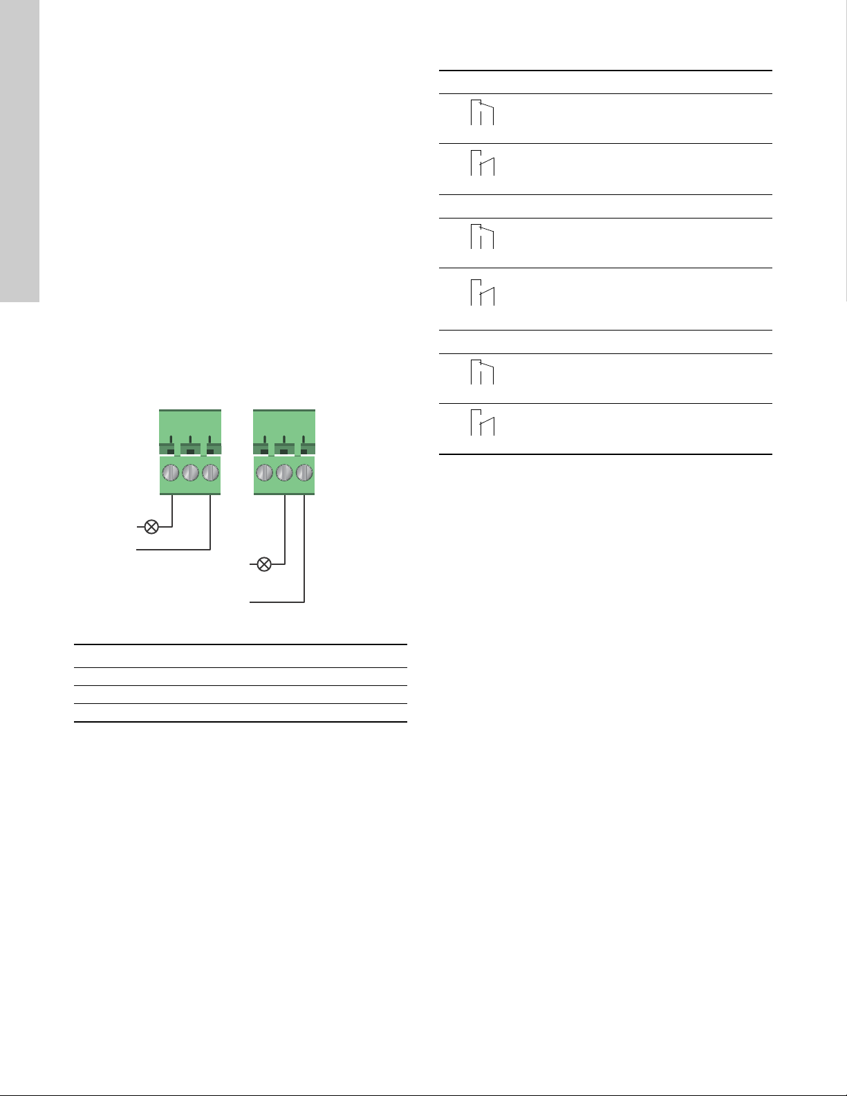
5.5.1 Relay outputs
See fig. 15, pos. 1.
The pump incorporates two signal relays with a potential-free
changeover contact for external fault indication.
The function of the signal relay can be set to "Alarm", "Ready" or
"Operation" on the pump control panel or with Grundfos GO
Remote.
The relays can be used for outputs up to 250 V and 2 A.
The functions of the signal relays appear from the table below:
Signal relay Alarm signal
Not activated:
• The power supply has been switched off.
• The pump has not registered a fault.
Activated:
• The pump has registered a fault.
Signal relay Ready signal
Not activated:
• The pump has registered a fault and is
unable to run.
Activated:
• The pump has been set to stop, but is ready
to run.
• The pump is running.
Signal relay Operating signal
Not activated:
• The pump is not running.
Activated:
• The pump is running.
Fig. 17 Relay output
Contact symbol Function
NC Normally closed
NO Normally open
C Common
TM05 3338 1212
16
Page 17
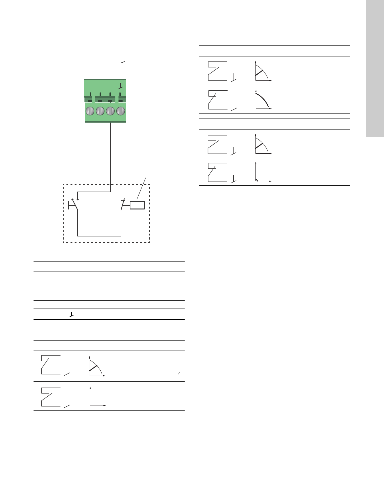
5.5.2 Digital inputs
S/S
M
I
M
A
On/off timer
Start/stop
S/S
S/S
M
A
M
A
Q
H
M
I
M
I
Q
H
See fig. 15, pos. 2.
The digital input can be used for external control of start/stop or
forced max. or min. curve.
If no external on/off switch is connected, the jumper between
terminals Start/Stop (S/S) and frame ( ) should be maintained.
This connection is the factory setting.
External forced max. or min. curve
The pump can be forced to operate on the max. or min. curve via
the digital input.
Max. curve
H
Normal duty
Q
Max. curve
Min. curve
H
Normal duty
Q
Min. curve
Select the function of the digital input on the pump control panel
or with Grundfos GO Remote.
English (US)
Fig. 18 Digital input
Contact symbol Function
M
A
M
I
S/S Start/Stop
External start/stop
The pump can be started or stopped via the digital input.
Start/stop
H
Q
H
Q
Max. curve
100 % speed
Min. curve
25 % speed
Frame connection
Normal duty
Note: Factory setting with
jumper between S/S and .
Stop
TM05 3339 1212
17
Page 18
English (US)
signal
sensor
Vcc
24V
I
N
-+
Sensor
Sensor
24V
IN
Vcc
Signal
1
2
24V
BMS
PLC
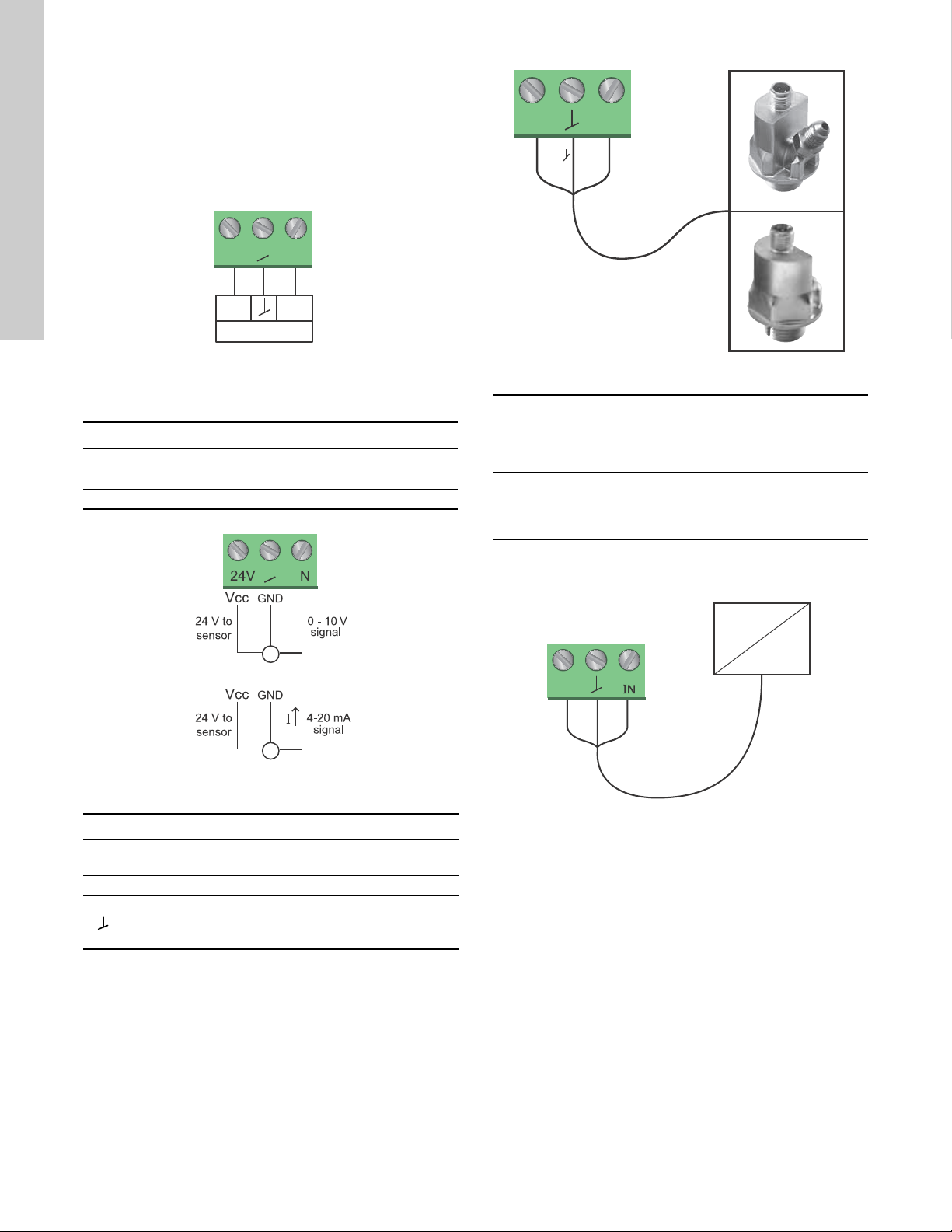
5.6 Analog input for external sensor
The analog input can be used for the connection of an external
sensor for measuring temperature or pressure.
The analog input can also be used for an external signal for the
control from a BMS system or similar control system.
The electrical signal for the input can be 0-10 VDC or 4-20 mA.
The selection of electrical signal (0-10 V or 4-20 mA) can be
changed on the control panel or with Grundfos GO Remote.
Fig. 19 Analog input for external sensor or control
In order to optimize the pump performance, external sensors can
advantageously be used in the following cases:
Function/control mode Sensor type
Heat energy meter Temperature sensor
Constant temperature Temperature sensor
Differential pressure Pressure sensor
Fig. 20 Wiring, analog input
PIN Description Load
IN Analog input
150 Ω (4-20 mA signal)
78 kΩ (0-10 V signal)
24 V 24 V supply to external sensor Max. 22 mA
TM05 3221 1112
Fig. 21 Examples of external sensors
Pos. Sensor type
Differential pressure transmitter,
1
Grundfos type DPI V.2
1/2" connection and 4-20 mA signal.
Relative pressure transmitter,
combined pressure and temperature sensor,
2
Grundfos type RPI/T G 1/2" connection and 4-20 mA
signal.
For further details, visit WebCAPS and reference Magna3 Data
booklet 98439208.
TM06 0882 1114
Fig. 22 Example of external signal for the control via BMS or
PLC
TM05 2947 1212
TM05 2888 0612
18
Ground for external sensor
Page 19
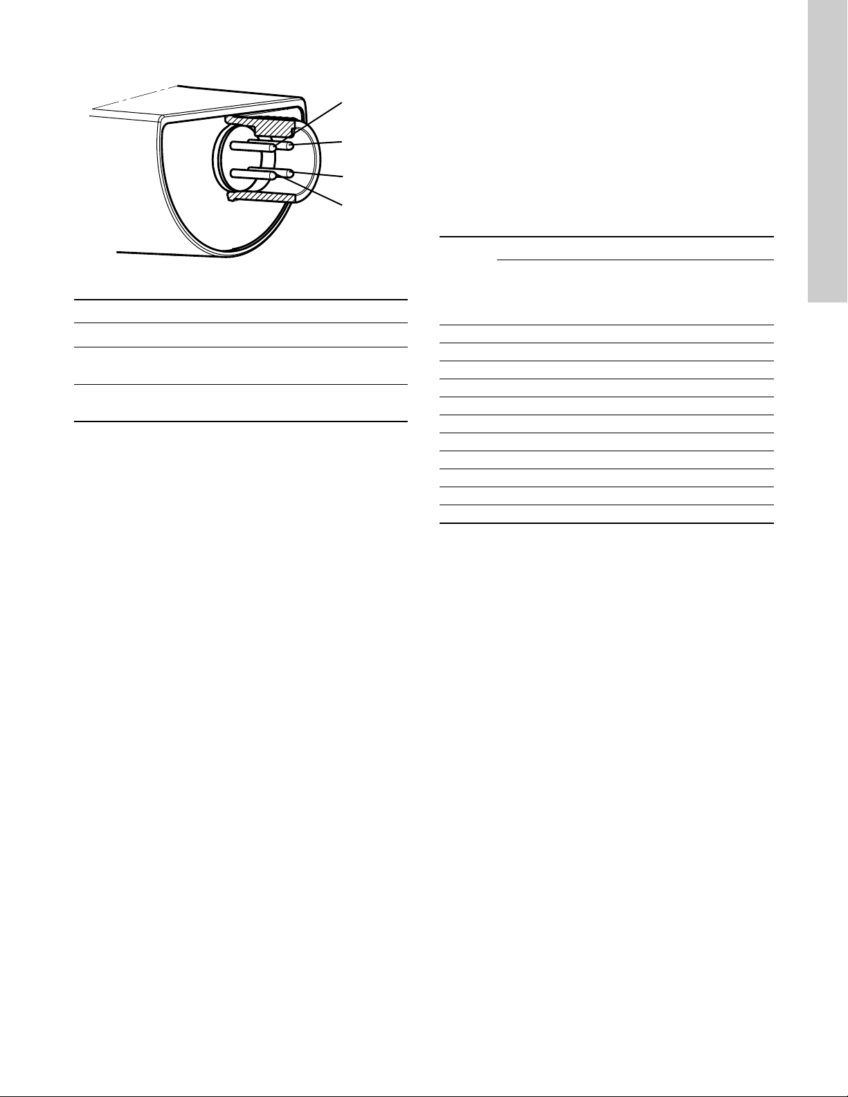
5.7 Electrical connection for external sensor
1
3
4
2
5.8 Priority of settings
The external forced-control signals will influence the settings
available on the pump control panel or with Grundfos GO
Remote. However, the pump can always be set to max. curve
duty or to stop on the pump control panel or with Grundfos GO
Remote.
If two or more functions are enabled at the same time, the pump
will operate according to the setting with the highest priority.
The priority of the settings is as shown in the table below.
Example: If the pump has been forced to stop via an external
signal, the pump control panel or Grundfos GO Remote can only
set the pump to max. curve.
English (US)
Fig. 23 Example electrical connections for external sensor
PIN 1 2 3 4
Wire color Brown Grey Blue Black
Output
4 to 20 mA
Output
2 x 0 to 10 V
* Common ground for both pressure and temperature signal.
* Power supply (screened cable): SELV or PELV.
+ not used - not used
Pressure
+
signal
-*
Temperature
signal
TM04 7156 1610
Priority
1 Stop
2 Max. curve
3Stop
4Stop
5Max. curve
6Min. curve
7Start
8Max. curve
9Min. curve
10 Min. curve
11 Star t
As illustrated in the table, the pump does not react to external
signals (max. curve and min. curve) when it is controlled via bus.
For further details, please contact Grundfos.
Pump control
panel or
Grundfos GO
Remote
Possible settings
External
signals
Bus signal
19
Page 20

English (US)
6. First start-up
Do not start the pump until the system has been filled with liquid
and vented. Furthermore, the required minimum inlet pressure
must be available at the pump inlet. See section 19. Technical
data.
The system cannot be vented through the pump. The pump is
self-venting.
Step Action Illustration
Switch on the power supply to the pump.
1
2
Note: When switched on, the pump will start in
AUTO
after approx. 5 seconds.
ADAPT
Pump display at first start-up.
After a few seconds, the pump display will change to the
start-up guide.
TM05 2884 0612
TM05 2885 0612
The start-up guide will guide you through the general
settings of the pump, such as language, date and time.
3
If the buttons on the pump control panel are not touched
for 15 minutes, the display will go into sleep mode.
When a button is touched, the "Home" display will appear.
TM05 2886 0612
When the general settings have been made, select the
4
desired control mode or let the pump run in AUTO
For additional settings, see section 7.
Settings
.
ADAPT
.
TM05 2887 0612
20
Page 21

7. Settings
7.1 Overview of settings
All settings can be made on the pump control panel or with Grundfos GO Remote.
Menu Submenu Further information
English (US)
Setpoint See section 13.1
Operating mode See section 13.2
• Normal
• Stop
• Min.
• Max.
Control mode See section 13.3
•AUTO
•FLOW
• Prop. press. See section 13.3.3 Proportional pressure.
• Const. press. See section 13.3.4 Constant pressure.
• Const. temp. See section 13.3.5 Constant temperature.
• Differential temperature See section 13.3.6 Differential temperature.
• Constant curve See section 13.3.7 Constant curve.
FLOW
LIMIT
• Set FLOW
Automatic Night Setback See section 13.5
• Not active
• Active
Relay outputs See section 13.6
• Relay output 1
• Relay output 2
Setpoint influence See section 13.7
• External setpoint function See section 13.7.1
• Temperature influence See section 13.7.2
Bus communication See section 13.8
• Pump number See section 13.8.1
General settings See section 13.9
• Language See section 13.9.1
• Set date and time See section 13.9.2
• Units See section 13.9.3
• Enable/disable settings See section 13.9.4
• Delete history See section 13.9.5
• Define Home display See section 13.9.6
• Display brightness See section 13.9.7
• Return to factory settings See section 13.9.8
• Run start-up guide See section 13.9.9
ADAPT
ADAPT
LIMIT
See section 13.3.1 AUTO
See section 13.3.2 FLOW
See section 13.4 FLOW
Setpoint
Operating mode
Control mode
.
ADAPT
ADAPT
LIMIT
.
.
.
.
.
Automatic Night Setback
Relay outputs
Setpoint influence
.
.
External setpoint function
Temperature influence
Bus communication
Pump number
General settings
Language
Set date and time
Units
.
.
.
.
.
.
Enable/disable settings
Delete history
.
Define Home display
Display brightness
.
Return to factory settings
Run start-up guide
.
.
.
.
.
.
.
21
Page 22

English (US)
8. Menu overview
Status Settings Assist
Operating status Setpoint Assisted pump setup
Operating mode, from Operating mode Setting of pump
Control mode Control mode Setting of date and time
Pump performance FLOW
Max. curve and duty point Enable FLOW
Resulting setpoint Set FLOW
LIMIT
LIMIT
function Date only
LIMIT
Liquid temperature Automatic Night Setback Multi-pump setup
Speed Relay outputs Setup, analog input
Operating hours Relay output 1 Description of control mode
Power and energy consumption Relay output 2 AUTO
Power consumption Not active FLOW
Energy consumption Ready Prop. press.
Warning and alarm Alarm Const. press.
Actual warning or alarm Operation Const. temp.
Warning log Setpoint influence Differential temperature
Warning log 1 to 5 External setpoint function Constant curve
Alarm log Temperature influence Assisted fault advice
Alarm log 1 to 5 Bus communication Blocked pump
Heat energy meter Pump number Pump communication fault
Heat power General settings Internal fault
Heat energy Language Internal sensor fault
Flow rate Set date and time Dry running
Volume Select date format Forced pumping
Hours counter Set date Undervoltage
Temperature 1 Select time format Overvoltage
Temperature 2 Set time External sensor fault
Differential temp. Units
Work log SI or US units
Operating hours Customized units
Trend data Pressure
Duty point over time Differential pressure
3D showing (Q, H, t) Head
3D showing (Q, T, t) Level
3D showing (Q, P, t) Flow rate
3D showing (T, P, t) Volume
Fitted modules Temperature
Date and time Differential temp.
Date Power
Time Energy
Pump identification Enable/disable settings
Multi-pump system Delete history
Operating status Delete work log
Operating mode, from Delete heat energy data
Control mode Delete energy consumption
System performance Define Home display
Duty point Select Home display type
Resulting setpoint List of data
System identification Graphical illustration
Power and energy consumption Define Home display contents
Power consumption List of data
Energy consumption Graphical illustration
Other pump 1, multi-pump sys. Display brightness
Brightness
Return to factory settings
Run start-up guide
Date format, date and time
Time only
ADAPT
ADAPT
22
Page 23

9. Control panel
Note
Note
Warnin g
At high liquid temperatures, the pump housing
may be very hot. In that case, only touch the
control panel.
10. Menu structure
The pump incorporates a start-up guide which is started at the
first start-up. After the start-up guide, the four main menus will
appear in the display. See section 6. First start-up.
1. Home
This menu shows up to four user-defined parameters with
shortcuts or a graphical illustration of a Q/H performance curve.
See section 11. "
2. Status
This menu shows the status of the pump and system as well as
warnings and alarms. See section 12. "
3. Settings
This menu gives access to all setting parameters. A detailed
setting of the pump can be made in this menu.
See section 13. "
4. Assist
This menu enables assisted pump setup, provides a short
description of the control modes and offers fault advice.
See section 14. "
Home
" menu.
Status
" menu.
No settings can be made in this menu.
Settings
Assist
" menu.
" menu.
11. "Home" menu
English (US)
Fig. 24 Control panel
Button Function
Goes to the "Home" menu.
Returns to the previous action.
Navigates between main menus, displays and
digits.
When the menu is changed, the display will always
show the top display of the new menu.
Navigates between submenus.
Saves changed values, resets alarms and expands
the value field.
TM05 7642 1313
Navigation
Home
Press to go to the "Home" menu.
"Home" menu (factory setting)
• Shortcut to control mode settings
• Shortcut to setpoint settings
• Flow rate
• Head.
Navigate in the display with or and change between the two
shortcuts with or .
The "Home" display can be defined by the user.
See section 13.9.6
Define Home display
.
TM05 7929 1613
23
Page 24
English (US)
12. "Status" menu
13. "Settings" menu
Navigation
Home > Status
Press and go to the "Status" menu with .
"Status" menu
This menu offers the following status information:
• Operating status
• Pump performance
• Power and energy consumption
• Warning and alarm
• Heat energy meter
• Work log
• Fitted modules
• Date and time
• Pump identification
• Multi-pump system.
Navigate between submenus with or .
2.1.0.0.0.0 Status
Navigation
Home > Settings
Press and go to the "Settings" menu with .
"Settings" menu
This menu offers the following setting options:
• Setpoint
• Operating mode
• Control mode
•FLOW
• Automatic Night Setback
• Relay outputs
• Setpoint influence
• Bus communication
• General settings.
Navigate between submenus with or .
LIMIT
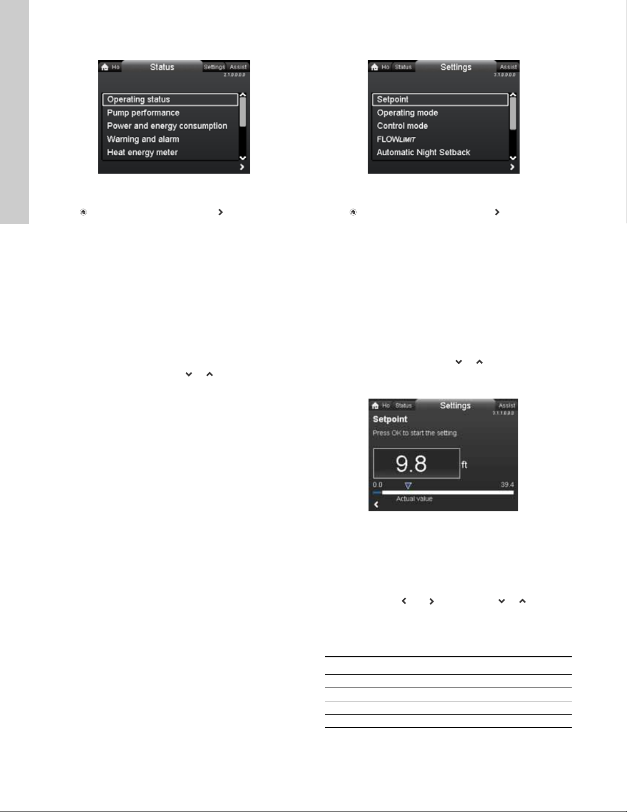
13.1 Setpoint
3.1.0.0.0.0 Settings
24
TM05 7925 1613
Navigation
Home > Settings > Setpoint
Setpoint
Set the setpoint so that it matches the system.
Setting:
1. Press [OK] to start the setting.
2. Select digit with and and adjust with or .
3. Press [OK] to save.
A too high setting may result in noise in the system whereas a too
low setting may result in insufficient heating or cooling in the
system.
Control mode Measuring unit
Proportional pressure m, ft
Constant pressure m, ft
Constant temperature °C, °F, K
Constant curve %
Page 25

13.2 Operating mode
H
Q
Max.
Min.
Note
Note
13.3 Control mode
English (US)
Navigation
Home > Settings > Operating mode
Operating mode
• Normal (control mode)
• Stop
• Min. (min. curve)
• Max. (max. curve).
Setting:
1. Select operating mode with or .
2. Press [OK] to save.
The pump can be set to operate according to the max. or min.
curve, like an uncontrolled pump. See fig. 25.
Fig. 25 Max. and min. curves
3.1.2.0.0.0 Operating mode
Navigation
Home > Settings > Control mode
Control mode
•AUTO
•FLOW
ADAPT
ADAPT
• Prop. press. (proportional pressure)
• Const. press. (constant pressure)
• Const. temp.(constant temperature)
• Constant curve.
The operating mode must be set to "
before a control mode can be enabled.
Setting:
1. Select control mode with or .
2. Press [OK] to enable.
The setpoint for all control modes, except AUTO
FLOW
"Settings" when the desired control mode has been selected.
, can be changed in the "Setpoint" submenu under
ADAPT
ADAPT
All control modes, except "Constant curve", can be combined with
Automatic Night Setback. See section 13.5
Setback
.
The FLOW
control modes mentioned above. See section 13.4 FLOW
TM05 2446 5111
function can also be combined with the last five
LIMIT
Automatic Night
Normal
and
"
LIMIT
3.1.3.0.0.0 Control mode
.
• Normal: The pump runs according to the selected control
mode.
• Stop: The pump stops.
• Min.: The min. curve mode can be used in periods in which a
minimum flow is required.
This operating mode is for instance suitable for manual night
setback if Automatic Night Setback is not desired.
• Max.: The max. curve mode can be used in periods in which a
maximum flow is required.
This operating mode is for instance suitable for hot-water
priority.
25
Page 26
English (US)
Note
Note
H
Q
H
auto_min
H
fac
A
1
A
3
A
2
H
set1
H
set2
H
Q
Q
max
90 %
H
auto_min
H
fac
Q
fac
Setting range
H
Q
H
set
H
set
2
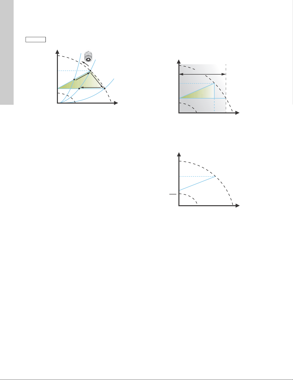
13.3.1 AUTO
The AUTO
performance according to the actual system characteristic.
ADAPT
control mode continuously adapts the pump
ADAPT
Manual setting of the setpoint is not possible.
Fig. 26 AUTO
When the AUTO
will start with the factory setting, H
ADAPT
control mode has been enabled, the pump
ADAPT
fac
= H
, corresponding to
set1
approx. 55 % of its maximum head, and then adjust its
performance to A
When the pump registers a lower head on the max. curve, A
AUTO
ADAPT
lower control curve, H
pump will adjust its performance to A
. See fig. 26.
1
function will automatically select a correspondingly
. If the valves in the system close, the
set2
.
3
, the
2
A1: Original duty point.
: Lower registered head on the max. curve.
A
2
: New duty point after AUTO
A
3
: Original setpoint setting.
H
set1
: New setpoint after AUTO
H
set2
: MAGNA3 xx-60: 11.4 ft (3.5 m)
H
fac.
ADAPT
ADAPT
control.
control.
MAGNA3 xx-80: 14.7 ft (4.5 m)
MAGNA3 xx-100: 18 ft (5.5 m)
MAGNA3 xx-120: 21.3 ft (6.5 m)
MAGNA3 xx-150: 26.2 ft (8.0 m)
MAGNA3 xx-180: 31.1 ft (9.5 m).
H
The AUTO
control where the control curves have a fixed origin, H
The AUTO
for heating systems and is not recommended for air-conditioning
: A fixed value of 4.9 ft (1.5 m).
auto_min
control mode is a form of proportional-pressure
ADAPT
control mode has been developed specifically
ADAPT
auto_min
.
and cooling systems.
To r e s et A U TO
settings
.
, see section 13.9.8
ADAPT
Return to factory
13.3.2 FLOW
When FLOW
ensure that the flow never exceeds the entered FLOW
The setting range for the FLOW
the pump.
The factory setting of the FLOW
AUTO
TM05 2452 1312
Fig. 27 FLOW
ADAPT
is selected, the pump will run AUTO
ADAPT
is 25 to 90 % of the Q
LIMIT
is the flow where the
factory setting meets the max. curve. See fig. 27.
ADAPT
ADAPT
LIMIT
13.3.3 Proportional pressure
The pump head is reduced at decreasing water demand and
increased at rising water demand. See fig. 28.
Fig. 28 Proportional pressure
ADAPT
LIMIT
and
value.
of
max
TM05 3334 1212 TM05 2448 1212
26
Page 27
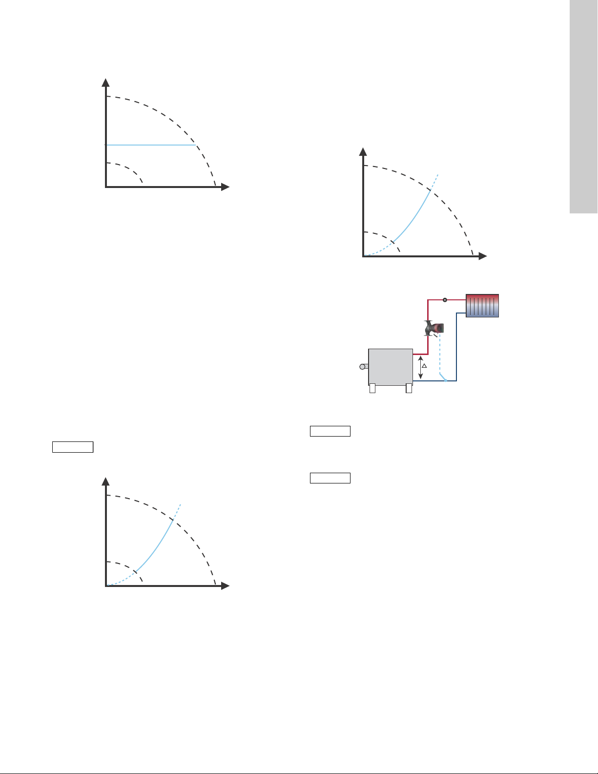
13.3.4 Constant pressure
Note
Note
H
Q
H
Q
Note
Note
Note
Note
H
Q
Δt
t
The pump maintains a constant pressure, irrespective of water
demand. See fig. 29.
Fig. 29 Constant pressure
13.3.5 Constant temperature
This control mode ensures a constant temperature.
Constant temperature is a comfort control mode that can be used
in domestic hot-water systems to control the flow to maintain a
fixed temperature in the system. See fig. 30. When this control
mode is used, no balancing valves must be installed in the
system.
If the pump is installed in the return pipe of the system, the
internal temperature sensor can be used. In this case, the pump
must be installed as close as possible to the consumer (radiator,
heat exchanger, etc.).
If the pump is installed in the flow pipe, an external temperature
sensor must be installed in the return pipe of the system.
The sensor must be installed as close as possible to the
consumer (radiator, heat exchanger, etc.).
The constant-temperature control mode also reduces the risk of
bacterial growth (for example Legionella) in the system.
It is possible to set the sensor range:
• min. +14 °F (-10 °C)
• max. +266 °F (+130 °C).
To ensure that the pump is able to control, we
recommend to set the sensor range between
+3 °F and +257 °F (-5 and +125 °C).
13.3.6 Differential temperature
This control mode ensures a constant differential temperature
drop across a heating system.
The pump should be installed in the flow pipe so the built-in
sensor measures the liquid temperature going out to the load.
An external temperature sensor must be installed in the system to
measure the liquid temperature returning from the heating load.
In this mode, the pump will maintain a constant temperature.
See figs 31 and 32, differential between the pump and the
external sensor.
TM05 2449 0312
Fig. 31 Differential temperature
Fig. 32 Differential temperature
Changing Kp and Ti values are only possible with
Grundfos GO.
Changing the Kp and Ti values will affect all
control modes. If the control mode is to be
changed back to another mode you must set the
K
and Ti values back to default values. For all
p
other modes the default values are K
T
= 0.5.
i
= 0.5,
p
English (US)
TM05 2451 5111TM05 8236 2113
TM05 2451 5111
Fig. 30 Constant temperature
27
Page 28
English (US)
t
L
2
[m]
Δt
L
2
[m]
L2 [m]
t
Note
Note
H
Q
H [%]
Q [m
3
/h]
100 %
Max. curve
Limited
max. curve
Actual duty point
See table, fig. 33.
The table shows the suggested controller settings:
K
p
System/application
Heating
system
1)
Cooling
system
2)
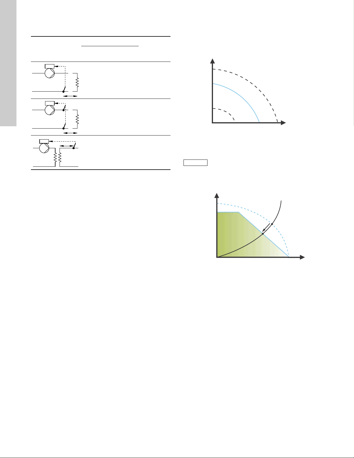
13.3.7 Constant curve
The pump can be set to operate according to a constant curve,
like an uncontrolled pump. See fig. 34.
The desired speed can be set in % of maximum speed in the
T
i
range from 25 to 100 %.
0.5 - 0.5 10 + 5L
-0.5 10 + 5L
0.5 - 0.5 30 + 5L
2
2
2
Fig. 33 Suggested controller settings
1)
Heating systems are systems in which an increase in pump
performance will result in a rise in temperature at the sensor.
2)
Cooling systems are systems in which an increase in pump
performance will result in a drop in temperature at the sensor.
L
= Distance in [m] between heat exchanger and sensor.
2
Proceed as follows:
1. Increase the gain (K
Instability can be seen by observing if the measured value
) until the motor becomes unstable.
p
starts to fluctuate. Furthermore, instability is audible as the
motor starts hunting up and down.
Some systems, such as temperature controls, are
slow-reacting, meaning that it may be several minutes before
the motor becomes unstable.
2. Set the gain (K
motor unstable. This is the correct setting of the gain.
3. Reduce the integral time (T
unstable.
4. Set the integral time (T
) to half the value of the value which made the
p
) until the motor becomes
i
) to twice the value which made the
i
motor unstable. This is the correct setting of the integral time.
General rules of thumb:
• If the controller is too slow-reacting, increase K
.
p
• If the controller is hunting or unstable, dampen the system by
reducing K
or increasing Ti.
p
TM05 2446 0312
Fig. 34 Constant curve
Depending on the system characteristic and the
duty point, the 100 % setting may be slightly
smaller than the pump's actual max. curve even
though the display shows 100 %. This is due to
power and pressure limitations built into the
pump. The deviation varies according to pump
type and pressure loss in the pipes.
TM05 3041 1212
Fig. 35 Power and pressure limitations influencing the max.
curve
28
Page 29

13.4 FLOW
H
Q
Q
max
Q
limit
90 %
Setting range
Note
Note
LIMIT
13.5 Automatic Night Setback
English (US)
LIMIT
Navigation
Home > Settings > FLOW
FLOW
LIMIT
• Enable FLOW
• Set FLOW
LIMIT
LIMIT
LIMIT
function
.
Setting:
1. To enable the function, select "Active" with or and press
[OK].
2. To set the FLOW
, press [OK] to start the setting.
LIMIT
3. Select digit with and and adjust with or .
4. Press [OK] to save.
Fig. 36 FLOW
The FLOW
control modes:
LIMIT
function can be combined with the following
LIMIT
• Prop. press.
• Const. press.
• Const. temp.
• Constant curve.
A flow-limiting function ensures that the flow never exceeds the
entered FLOW
The setting range for FLOW
LIMIT
value.
is 25 to 90 % of the Q
LIMIT
max
of the
pump.
The factory setting of the FLOW
AUTO
factory setting meets the max. curve. See fig. 27.
ADAPT
is the flow where the
LIMIT
3.1.5.0.0.0 FLOW
Navigation
Home > Settings > Automatic Night Setback
Automatic Night Setback
To enable the function, select "Active" with or and press
[OK].
Once Automatic Night Setback has been enabled, the pump
automatically changes between normal duty and night setback
(duty at low performance).
Changeover between normal duty and night setback depends on
the flow-pipe temperature.
The pump automatically changes over to night setback when the
built-in sensor registers a flow-pipe temperature drop of more
than +18 to +27 °F (-8 to -3 °C) within approx. two hours.
The temperature drop must be at least 0.18 °F/min (0.1 °C/min).
Changeover to normal duty takes place without a time lag when
the temperature has increased by approx. +18 °F (-8 °C).
Automatic Night Setback cannot be enabled
when the pump is in constant-curve mode.
TM05 2445 1212
3.1.6.0.0.0 Automatic Night Setback
29
Page 30
English (US)
Note
Note
rpm
V
Min.
02
Max.
10
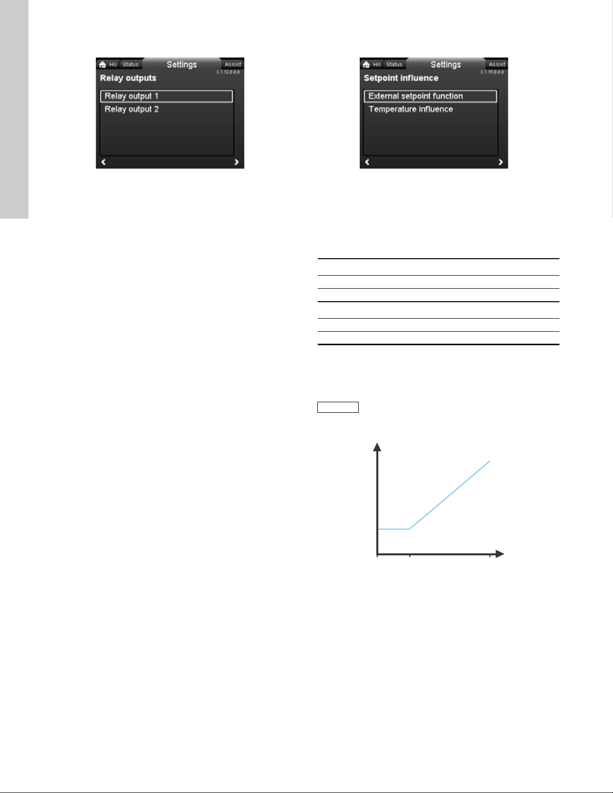
13.6 Relay outputs
13.7 Setpoint influence
Navigation
Home > Settings > Relay outputs
Relay outputs
• Relay output 1
• Relay output 2.
The relay outputs can be set to the following:
• Not active
• Ready
• Alarm
• Operation.
The pump incorporates two signal relays, terminals 1, 2 and 3, for
a potential-free alarm signal, ready signal and operating signal.
For further information, see section 5.5.1 Relay outputs.
Set the function of the signal relays, alarm signal (factory setting),
ready signal and operating signal, on the pump control panel.
The output, terminals 1, 2 and 3, is electrically separated from the
rest of the controller.
The signal relay is operated as follows:
• Not active
The signal relay is deactivated.
• Ready
The signal relay is active when the pump is running or has
been set to stop, but is ready to run.
• Alarm
The signal relay is activated together with the red indicator
light on the pump.
• Operation
The signal relay is activated together with the green indicator
light on the pump.
3.1.12.0.0.0 Relay outputs
Navigation
Home > Settings > Setpoint influence
Setpoint influence
• External setpoint function
• Temperature influence.
13.7.1 External setpoint function
Range
4-20 mA [0-100 %]
0-10 V [0-100 %]
Control
0-20 % (e.g. 0-2 V) Setpoint = Min.
20-100 % (e.g. 2-10 V) Setpoint = Min. ↔ setpoint
The external setpoint function is an external 0-10 V or 4-20 mA
signal that will control the pump speed in a range from 0 to 100 %
in a linear function. See fig. 37.
Before the "
External setpoint function
" can be
enabled, the analog input must be set to "
setpoint influence
" via the "
Assist
" menu.
See section 5.6 Analog input for external sensor.
3.1.15.0.0.0 Setpoint influence
External
30
TM05 3219 1212
Fig. 37 External setpoint function, 0-10 V
Page 31

13.7.2 Temperature influence
Note
Note
H
T [°F]
30 %
68 122 176
T [°C]
20 50 80
100 %
H
actual
T
actual
H
Q
When this function is enabled in proportional- or
constant-pressure control mode, the setpoint for head will be
reduced according to the liquid temperature.
Temperature influence can be set to function at liquid
temperatures below +176 °F or +122 °F (80 °C or 50 °C).
These temperature limits are called T
reduced in relation to the head set (= 100 %) according to the
. The setpoint is
max.
characteristics below.
Fig. 38 Temperature influence
13.8 Bus communication
13.8.1 Pump number
Navigation
Home > Settings > Bus communication > Pump number
Pump number
A unique number can be allocated to the pump. This makes it
possible to distinguish between pumps in connection with bus
communication.
13.9 General settings
TM05 7946 1613
13.9.1 Language
English (US)
3.1.18.1.0.0 Pump number
In the above example, T
= +176 °F (+80 °C) has been
max.
selected.
The actual liquid temperature T
to be reduced from 100 % to H
causes the setpoint for head
actual
.
actual
The temperature influence function requires the following:
• Proportional-pressure, constant-pressure or constant-curve
control mode.
• Pump installed in flow pipe.
• System with flow-pipe temperature control.
Temperature influence is suitable for the following systems:
• Systems with variable flows (for example two-pipe heating
systems) in which the enabling of the temperature influence
function will ensure a further reduction of the pump
performance in periods with small heating demands and
consequently a reduced flow-pipe temperature.
• Systems with almost constant flows (for example one-pipe
heating systems and underfloor heating systems), in which
variable heating demands cannot be registered as changes in
the head as is the case with two-pipe heating systems. In such
systems, the pump performance can only be adjusted by
enabling the temperature influence function.
Selection of T
max.
In systems with a dimensioned flow-pipe temperature of:
• up to and including +131 °F (+55 °C), select T
(+50 °C)
• above +131 °F (+55 °C), select T
= +176 °F (80 °C).
max.
max.
= +122 °F
The temperature influence function cannot be
used in air-conditioning and cooling systems.
TM05 7947 1613
Navigation
Home > Settings > General settings > Language
Language
The display can be shown in any of the following languages:
GB, BG, CZ, DK, DE, EE, GR, ES, FR, HR, IT, LV, LT, HU, NL,
UA, PL, PT, RU, RO, SK, SI, RS, FI, SE, TR, CN, JP or KO.
Measuring units are automatically changed according to selected
language.
Setting:
1. Select language with and .
2. Press [OK] to enable.
31
Page 32

English (US)
13.9.2 Set date and time
13.9.3 Units
Navigation
Home > Settings > General settings > Set date and time
Set date and time
• Select date format
• Set date
• Select time format
• Set time.
Set the real-time clock in this menu.
Select date format
• YYYY-MM-DD
• DD-MM-YYYY
• MM-DD-YYYY.
Setting:
1. Select "Set date".
2. Press [OK] to start the setting.
3. Select digit with and and adjust with or .
4. Press [OK] to save.
Select time format
• HH:MM 24-hour clock
• HH:MM am/pm 12-hour clock.
Setting:
1. Select "Set time".
2. Press [OK] to start the setting.
3. Select digit with and and adjust with or .
4. Press [OK] to save.
3.1.19.2.0.0 Set date and time
Navigation
Home > Settings > General settings > Units
Units
• SI or US units
• Customized units.
Select whether the display should shows SI or US units or select
the desired units for the parameters below.
• Pressure
• Differential pressure
• Head
• Level
• Flow rate
• Volume
• Temperature
• Differential temp.
• Power
• Energy.
Setting:
1. Select parameter and press [OK].
2. Select unit with or .
3. Press [OK] to enable.
If "SI or US units" is selected, the customized units will be reset.
3.1.19.3.0.0 Units
32
Page 33

13.9.4 Enable/disable settings
13.9.6 Define Home display
English (US)
Navigation
Home > Settings > General settings > Enable/disable settings
Enable/disable settings
In this display, the possibility of making settings can be disabled
for protective reasons.
Select "Disable" with or and press [OK].
The pump will now be locked for settings. Only the "Home"
display will be available.
To unlock the pump and allow settings, press and
simultaneously for at least 5 seconds.
13.9.5 Delete history
Navigation
Home > Settings > General settings > Delete history
Delete history
• Delete work log
• Delete heat energy data
• Delete energy consumption.
It is possible to delete data from the pump, for example if the
pump is moved to another system or if new data are required due
to changes to the system.
Setting:
1. Select the relevant submenu and press [OK].
2. Select "Yes" with or and press [OK] or press to
cancel.
3.1.19.4.0.0 Enable/disable settings3.1.19.5.0.0 Delete history
Navigation
Home > Settings > General settings > Define Home display
Define Home display
• Select Home display type
• Define Home display contents.
The "Home" display can be set to show up to four user-defined
parameters or a graphical illustration of a performance curve.
Select Home display type
1. Select "List of data" or "Graphical illustration" with or .
2. Press [OK] to save.
To specify the contents, go to "Define Home display contents".
Define Home display contents
1. To set "List of data", press [OK] to start the setting.
A list of parameters will appear in the display.
2. Select or deselect with [OK].
Up to four parameters can be selected.
The selected parameters will be shown as illustrated below.
The arrow icon indicates that the parameter links to the "Settings"
menu and works as a shortcut for quick settings.
1. To set "Graphical illustration", press [OK] to start the setting.
2. Select the desired curve and press [OK] to save.
3.1.19.6.0.0 Define Home display
TM05 7929 1613
33
Page 34

English (US)
13.9.7 Display brightness
13.9.9 Run start-up guide
Navigation
Home > Settings > General settings > Display brightness
Brightness
1. Press [OK] to start the setting.
2. Set brightness with and .
3. Press [OK] to save.
13.9.8 Return to factory settings
Navigation
Home > Settings > General settings > Return to factory settings
Return to factory settings
It is possible to recall the factory settings and overwrite the
current settings. All user settings in the "Settings" and "Assist"
menus will be set back to the factory settings. This also includes
language, units, possible setup of analog input, multi-pump
function, etc.
To overwrite the current settings with the factory settings, select
"Yes" with or and press [OK].
3.1.19.7.1.0 Brightness3.1.19.10.1.0 Return to factory settings
Navigation
Home > Settings > General settings > Run start-up guide
Run start-up guide
It is possible to run the start-up guide again. The start-up guide
will guide the user through the general settings of the pump, such
as language, date and time.
To run the start-up guide, select "Yes" with or and press
[OK].
3.1.19.11.0.0 Run start-up guide
34
Page 35

14. "Assist" menu
Navigation
Home > Assist
Press and go to the "Assist" menu with .
"Assist" menu
This menu offers the following:
• Assisted pump setup
• Setting of date and time
• Multi-pump setup
• Setup, analog input
• Description of control mode
• Assisted fault advice.
The "Assist" menu guides the user through the setting of the
pump. In each submenu, the user is presented with a guide that
helps throughout the setting.
14.1 Assisted pump setup
This submenu is a step-by-step guide to complete pump setup,
starting with a presentation of the control modes and ending with
the setpoint setting.
14.2 Setting of date and time
See section 13.9.2
14.3 Multi-pump setup
This submenu assists the user in setting up a multi-pump system.
See section 14.8 M ulti-pump function.
14.4 Setup, analog input
This submenu assists the user in setting up the analog input.
14.5 Description of control mode
This submenu gives a short description of each control mode.
14.6 Assisted fault advice
This submenu provides information about faults and corrective
actions.
Set date and time
.
14.7 Wireless GENIair
The pump is designed for multi-pump connection via the wireless
GENIair connection or wired via a bus system (Building
Management System).
The built-in wireless GENIair module enables communication
between pumps and with Grundfos Go Remote without the use of
add-on modules:
• Multi-pump function.
See section 14.8 M ulti-pump function.
• Grundfos GO Remote.
See section 18.1 Grundfos GO Remote.
14.8 Multi-pump function
Assist
The multi-pump function enables the control of single-head
pumps connected in parallel and twin-head pumps without the
use of external controllers. The pumps in a multi-pump system
communicate with each other via the wireless GENIair
connection.
A multi-pump system is set up via a selected pump, i.e. the
master pump (first selected pump). All Grundfos pumps with a
wireless GENIair connection can be connected to the multi-pump
system.
The multi-pump functions are described in the following sections.
14.8.1 Alternating operation
Only one pump is operating at a time. The change from one pump
to the other depends on time or energy. If a pump fails, the other
pump will take over automatically.
Pump system:
• Twin-head pump.
• Two single-head pumps connected in parallel. The pumps
must be of same type and size. Each pump requires a
non-return valve in series with the pump.
14.8.2 Back-up operation
One pump is operating continuously. The back-up pump is
operated at intervals to prevent seizing up. If the duty pump stops
due to a fault, the back-up pump will start automatically.
Pump system:
• Twin-head pump.
• Two single-head pumps connected in parallel. The pumps
must be of same type and size. Each pump requires a
non-return valve in series with the pump.
14.8.3 Cascade operation
Cascade operation ensures that the pump performance is
automatically adapted to the consumption by switching pumps on
or off. The system thus runs as energy-efficiently as possible with
a constant pressure and a limited number of pumps.
All pumps in operation will run at equal speed. Pump changeover
is automatic and depends on energy, operating hours and fault.
Pump system:
• Twin-head pump.
• Two single-head pumps connected in parallel. The pumps
must be of same type and size. Each pump requires a
non-return valve in series with the pump.
• The control mode must be set to "Const. press." or "Constant
curve".
English (US)
35
Page 36

English (US)
H
Q
H
Q
H
Q
H
set
H
set
2
H
Q
15. Selection of control mode
System application
Recommended for most heating systems, especially in systems with relatively large pressure losses in the
distribution pipes. See description under proportional pressure.
In replacement situations where the proportional-pressure duty point is unknown.
The duty point has to be within the AUTO
makes the necessary adjustment to the actual system characteristic.
operating range. During operation, the pump automatically
ADAPT
This setting ensures minimum energy consumption and noise level from valves, which reduces operating costs
and increases comfort.
The FLOW
This control mode is suitable for systems where a maximum flow limit, FLOW
continuously monitors and adjusts the flow, thus ensuring that the selected FLOW
Main pumps in boiler applications where a steady flow through the boiler is required. No extra energy is used for
control mode is a combination of AUTO
ADAPT
ADAPT
and FLOW
.
LIMIT
, is desired. The pump
LIMIT
is not exceeded.
LIMIT
pumping too much liquid into the system.
In systems with mixing loops, the control mode can be used to control the flow in each loop.
Benefits:
• Enough water for all loops at peak load conditions if each loop has been set to the right maximum flow.
• The dimensioned flow for each zone (required heat energy) is determined by the flow from the pump.
This value can be set precisely in the FLOW
control mode without the use of pump throttling valves.
ADAPT
• When the flow is set lower than the balancing valve setting, the pump will ramp down instead of losing energy
by pumping against a balancing valve.
• Cooling surfaces in air-conditioning systems can operate at high pressure and low flow.
In systems with relatively large pressure losses in the distribution pipes and in air-conditioning and cooling systems.
• Two-pipe heating systems with thermostatic valves and
– a dimensioned pump head higher than 13 ft (4 meters)
– very long distribution pipes
– strongly throttled pipe balancing valves
– differential-pressure regulators
– large pressure losses in those parts of the system through which the total quantity of water flows (for
example boiler, heat exchanger and distribution pipe up to the first branching).
• Primary circuit pumps in systems with large pressure losses in the primary circuit.
• Air-conditioning systems with
– heat exchangers (fan coils)
– cooling ceilings
– cooling surfaces.
In systems with relatively small pressure losses in the distribution pipes.
• Two-pipe heating systems with thermostatic valves and
– a dimensioned pump head lower than 6.5 ft (2 meters)
– dimensioned for natural circulation
– small pressure losses in those parts of the system through which the total quantity of water flows (for
example boiler, heat exchanger and distribution pipe up to the first branching) or
– modified to a high differential temperature between flow pipe and return pipe (for example district heating).
• Underfloor heating systems with thermostatic valves.
• One-pipe heating systems with thermostatic valves or pipe balancing valves.
• Primary circuit pumps in systems with small pressure losses in the primary circuit.
Select this control
mode
AUTO
ADAPT
FLOW
ADAPT
Proportional
pressure
Constant pressure
36
Page 37

System application
H
Q
H
Q
ΔT
H
Q
In heating systems with a fixed system characteristic, for example domestic hot-water systems, the control of the
pump according to a constant return-pipe temperature may be relevant.
FLOW
can be used with advantage to control the maximum circulation flow.
LIMIT
In a heating system where a constant temperature drop across the system is desired, constant differential
temperature can be used.
This mode requires an external temperature sensor for the second temperature measurement.
Select this control
mode
Constant
temperature
English (US)
Differential
temperature
If an external controller is installed, the pump is able to change from one constant curve to another, depending
on the value of the external signal.
The pump can also be set to operate according to the max. or min. curve, like an uncontrolled pump:
• The max. curve mode can be used in periods in which a maximum flow is required. This operating mode is for
instance suitable for hot-water priority.
• The min. curve mode can be used in periods in which a minimum flow is required. This operating mode is for
instance suitable for manual night setback if Automatic Night Setback is not desired.
In systems with pumps operating in parallel.
The multi-pump function enables the control of single-head pumps connected in parallel (two pumps) and
twin-head pumps without the use of external controllers. The pumps in a multi-pump system communicate with
each other via the wireless GENIair connection.
Constant curve
"Assist" menu
"Multi-pump setup"
37
Page 38

English (US)
16. Fault finding
Warning
Before dismantling the pump, drain the system or close the isolating valve on either side of the pump.
The pumped liquid may be scalding hot and under high pressure.
16.1 Grundfos Eye operating indications
Grundfos Eye Indication Cause
No lights on.
Two opposite green indicator lights running in the
direction of rotation of the pump.
Two opposite green indicator lights permanently
on.
One yellow indicator light running in the direction
of rotation of the pump.
One yellow indicator light permanently on.
Two opposite red indicator lights flashing
simultaneously.
One green indicator light in the middle
permanently on (in addition to another
indication).
Power off.
Pump not running.
Power on.
Pump running.
Power on.
Pump not running.
Warning.
Pump running.
Warning.
Pump stopped.
Alarm.
Pump stopped.
Remote-controlled.
The pump is currently being accessed by
Grundfos GO Remote.
16.2 Signalling communication with remote control
The center indicator light in the Grundfos Eye will indicate communication with Grundfos GO Remote.
The table below describes the desired function of the center indicator light.
Case Description Signalling by the center indicator light
Four or five quick flashes once to signal
"I am here".
Flashing continuously with 50 % duty
cycle.
Indicator light permanently on.
Wink
Push me
I am connected
The pump in question is highlighted in the Grundfos GO Remote display.
To inform the user of the location of the highlighted pump, the center
indicator light will flash four or five times once to signal "I am here".
The pump in question is selected/opened in the Grundfos GO Remote
menu. The pump will signal "Push me" to ask the user to select the
pump/allow the pump to exchange data with Grundfos GO Remote.
The indicator light will flash continuously until a pop-up window asks the
user to press [OK] to allow communication with Grundfos GO Remote.
The indicator light is signalling that the pump is connected to Grundfos
GO Remote. The indicator light is permanently on as long as the pump is
selected in Grundfos GO Remote.
38
Page 39

16.3 Fault finding
Caution
A fault indication can be reset in one of the following ways:
• When the fault cause has been eliminated, the pump will
revert to normal duty.
• If the fault disappears by itself, the fault indication will
automatically be reset.
• The fault cause will be stored in the pump alarm log.
English (US)
Warning and alarm codes Fault
Pump communication fault (10)
Alarm
Forced pumping (29)
Alarm
Undervoltage (40, 75)
Alarm
Blocked pump (51)
Alarm
Dry running (57)
Alarm
High motor temperature (64)
Alarm
Internal fault (72, 84, 155, 157)
Warning/alarm
Overvoltage (74)
Alarm
Communication fault, twin-head
pump (77)
Warning
Internal sensor fault (88)
Warning
External sensor fault (93)
Warning
Communication fault between
different parts of the
electronics.
Other pumps or sources force
flow through the pump even if
the pump is stopped and
switched off.
Supply voltage to the pump
too low.
The pump is blocked. No
No water at the pump inlet or
the water contains too much
air.
Temperature in stator windings
too high.
Internal fault in the pump
electronics.
Supply voltage to the pump
too high.
Communication between
pump heads disturbed or
broken.
The pump is receiving a signal
from the internal sensor which
is outside the normal range.
The pump is receiving a signal
from the external sensor which
is outside the normal range.
Automatic reset
and restart?
Yes
Yes
Yes
No
No
Yes
Yes
Yes
Yes
Yes
Corrective actions
Replace the pump, or call GRUNDFOS
SERVICE for assistance.
Check if the pump is running in turbine operation.
See code (29) Forced pumping.
Switch off the pump on the main switch. If the
light in the Grundfos Eye is on, the pump is
running in forced-pumping mode.
Check the system for defective non-return valves
and replace, if necessary.
Check the system for correct position of
non-return valves, etc.
Check that the power supply is within the
specified range.
Dismantle the pump, and remove any foreign
matter or impurities preventing the pump from
rotating.
Prime and vent the pump before a new start-up.
Check that the pump is operating correctly. If not,
replace the pump, or call GRUNDFOS SERVICE
for assistance.
Check the winding resistance according to the
MAGNA3 service instructions.
Replace the pump, or call GRUNDFOS
SERVICE for assistance.
Check that the power supply is within the
specified range.
Check that the second pump head is powered or
connected to the power supply.
Check that the plug and cable are connected
correctly in the sensor. The sensor is located on
the back of the pump housing.
Replace the sensor, or call GRUNDFOS
SERVICE for assistance.
Does the electrical signal set (0-10 V or 4-20 mA)
match the sensor output signal?
If not, change the setting of the analog input, or
replace the sensor with one that matches the
setup.
Check the sensor cable for damage.
Check the cable connection at the pump and at
the sensor. Correct the connection, if required.
The sensor has been removed, but the analog
input has not been disabled.
Replace the sensor, or call GRUNDFOS
SERVICE for assistance.
If the power supply cable is damaged, it must be replaced by the manufacturer, the manufacturer's service partner or
a similarly qualified person.
39
Page 40

English (US)
Nose downwards
5 Nm
17. Sensor
TM05 3036 0812
Fig. 39 Correct position of sensor
During maintenance and replacement of the sensor, it is
important that the sealing cap is fitted correctly on the sensor
housing.
Tighten the screw holding the clamp to 3.7 ft-lbs (5 Nm).
Warnin g
Before replacing the sensor, make sure that the
pump is stopped and that the system is not
pressurized.
17.1 Sensor specifications
17.1.1 Pressure
Maximum differential pressure
during operation
Accuracy
+32 to +185 °F (0 to +85 °C)
Accuracy
+14 to +32 °F and +185 to +266 °F
(-10 to 0 °C and +85 to +130 °C)
* Full scale.
17.1.2 Temperature
Temperature range during operation
Accuracy
29 psi / 2 bar / 0.2 MPa
2 %*
3 %*
+14 to +266 °F
(-10 to +130 °C)
± 3.6 °F
(± 2 °C)
40
Page 41

18. Accessories
Note
Note
Note
Note
18.1 Grundfos GO Remote
MAGNA3 is designed for wireless communication with the
Grundfos GO Remote app. The Grundfos GO Remote app
communicates with the pump via radio communication (wireless
GENIair).
The radio communication between the pump and
Grundfos GO Remote is encrypted to protect
against misuse.
The Grundfos GO Remote app is available from Apple AppStore
and Android market.
The Grundfos GO Remote concept replaces the Grundfos R100
remote control. This means that all products supported by the
R100 are supported by Grundfos GO Remote.
Grundfos GO Remote can be used for the following:
• Reading of operating data.
• Reading of warning and alarm indications.
• Setting of control mode.
• Setting of setpoint.
• Selection of external setpoint signal.
• Allocation of pump number making it possible to distinguish
between pumps that are connected via Grundfos GENIbus.
• Selection of function for digital input.
• Generation of reports (PDF).
• Assist function.
• Multi-pump setup.
• Display of relevant documentation.
For function and connection to the pump, see separate
installation and operating instructions for the desired type of
Grundfos GO Remote setup.
18.2 Communication
The pump can communicate via the wireless GENIair connection
or a CIM module.
This enables the pump to communicate with other pumps and
with different types of network solutions.
The Grundfos CIM modules (CIM = Communication Interface
Module) enable the pump to connect to standard fieldbus
networks.
Fig. 40 Building management system (BMS) with four pumps
connected in parallel
A CIM module is an add-on communication interface module.
The CIM module enables data transmission between the pump
and an external system, for example a BMS or SCADA system.
The CIM module communicates via fieldbus protocols.
A gateway is a device that facilitates the transfer
of data between two different networks based on
different communication protocols.
The following CIM modules are available:
Module Fieldbus protocol Product number
CIM 050 GENIbus 96824631
CIM 100 LonWorks 96824797
CIM 150 PROFIBUS DP 96824793
CIM 200 Modbus RTU 96824796
CIM 250 GSM/GPRS 96824795
CIM 270 GRM 96898815
CIM 300 BACnet MS/TP 96893770
CIM 500 Ethernet 98301408
English (US)
TM05 2710 0612
41
Page 42

English (US)
18.2.1 Description of CIM modules
Module
CIM 050
CIM 100
CIM 150
CIM 200
CIM 250
Fieldbus
protocol
GENIbus
TM05 3812 1612
LonWorks
TM05 3813 1612
PROFIBUS DP
TM05 3814 1612
Modbus RTU
TM05 3815 1612
GSM/GPRS
TM05 4432 2212
Description Functions
CIM 050 is a Grundfos
communication interface
module used for
CIM 050 has terminals for the GENIbus connection.
communication with a
GENIbus network.
CIM 100 is a Grundfos
communication interface
module used for
communication with a
LonWorks network.
CIM 100 has terminals for the LonWorks connection.
Two LEDs are used to indicate the actual status of the
CIM 100 communication.
One LED is used for indication of correct connection to the
pump, and the other is used to indicate LonWorks
communication status.
CIM 150 has terminals for the PROFIBUS DP connection.
DIP switches are used to set line termination.
CIM 150 is a Grundfos
communication interface
module used for
communication with a
PROFIBUS network.
Two hexadecimal rotary switches are used to set the
PROFIBUS DP address.
Two LEDs are used to indicate the actual status of the
CIM 150 communication.
One LED is used for indication of correct connection to the
pump, and the other is used to indicate PROFIBUS
communication status.
CIM 200 has terminals for the Modbus connection.
DIP switches are used to select parity and stop bits, to
CIM 200 is a Grundfos
communication interface
module used for
communication with a
Modbus RTU network.
select transmission speed and to set line termination.
Two hexadecimal rotary switches are used to set the
Modbus address.
Two LEDs are used to indicate the actual status of the
CIM 200 communication.
One LED is used for indication of correct connection to the
pump, and the other is used to indicate Modbus
communication status.
CIM 250 has a SIM-card slot and an SMA connection to
the GSM antenna.
CIM 250 also has an internal backup battery. Two LEDs
CIM 250 is a Grundfos
communication interface
module used for GSM/GPRS
communication.
CIM 250 is used to
communicate via a GSM
network.
are used to indicate the actual status of the CIM 250
communication. One LED is used for indication of correct
connection to the pump, and the other is used to indicate
GSM/GPRS communication status.
Note: The SIM card is not supplied with CIM 250. The SIM
card from the service provider must support data/fax
service to use call service from PC Tool or SCADA.
The SIM card from the service provider must support
GPRS service to use Ethernet service from PC Tool or
SCADA.
42
Page 43

Module
CIM 270
CIM 300
CIM 500
Fieldbus
protocol
Grundfos Remote
Management
TM05 4432 2212
BACnet MS/TP
TM05 3815 1612
Description Functions
CIM 270 is a Grundfos
GSM/GPRS modem used
for communication with a
Grundfos Remote
Management system.
It requires a GSM antenna,
a SIM card and a contract
with Grundfos.
With CIM 270 you have wireless access to your account
anywhere, anytime when you have an internet connection,
for example via a smartphone, tablet PC, laptop or
computer. Warnings and alarms can be sent by e-mail or
SMS to your mobile phone or computer. You will get a
complete status overview of the entire GRM system.
It allows you to plan maintenance and service based on
actual operating data.
CIM 300 has terminals for the BACnet MS/TP connection.
DIP switches are used to set transmission speed and line
termination and to select the custom Device Object
CIM 300 is a Grundfos
communication interface
module used for
communication with a
BACnet MS/TP network.
Instance Number.
Two hexadecimal rotary switches are used to set the
BACnet address.
Two LEDs are used to indicate the actual status of the
CIM 300 communication.
One LED is used for indication of correct connection to the
pump, and the other is used to indicate BACnet
communication status.
English (US)
CIM 500 is a Grundfos
communication interface
Ethernet
module used for data
transmission between an
industrial Ethernet network
and a Grundfos product.
TM05 8825 2713
18.2.2 Grundfos Remote Management
Grundfos Remote Management is an easy-to-install, low-cost
solution for wireless monitoring and management of Grundfos
products. It is based on a centrally hosted database and a web
server with wireless data collection via GSM/GPRS modem.
The system only requires an internet connection, a web browser,
a GRM modem and an antenna as well as a contract with
Grundfos allowing you to monitor and manage Grundfos pump
systems.
You have wireless access to your account anywhere, anytime
when you have an internet connection, for example via a
smartphone, tablet PC, laptop or computer. Warnings and alarms
can be sent by e-mail or SMS to your mobile phone or computer.
Application Description
Product
number
Grundfos Remote Management
CIM 270
(requires a contract with Grundfos
96898815
and a SIM card).
Antenna for use on top of metal
GSM antenna
for
roof-mounting
cabinets.
Vandal-proof.
2-metre cable.
97631956
Quad band (global use).
Antenna for general-purpose
application, for example inside
GSM antenna
for
desk-mounting
plastic cabinets.
To be fixed with the
double-adhesive tape supplied.
97631957
4-metre cable.
Quad band (global use).
CIM 500 supports various industrial Ethernet protocols.
CIM 500 is configured via the built-in web server, using a
standard web browser on a PC.
See the specific functional profile on the DVD-ROM
supplied with the Grundfos CIM module.
For GRM contract, contact your local Grundfos company.
18.2.3 Reuse of CIM modules
A CIM module in a CIU unit used together with GRUNDFOS
MAGNA can be reused in MAGNA3.
The CIM module has to be re-configured before it is used in a
MAGNA3 pump. Contact your nearest Grundfos company.
TM05 2911 1312
Fig. 41 Reuse of CIM module
43
Page 44

English (US)
18.3 Fitting the CIM module
Warnin g
Before fitting the module, switch off the power supply. Make sure that the power supply cannot be accidentally
switched on.
Step Action Illustration
1 Remove the front cover from the control box.
TM05 2875 0912
2 Fit the CIM module as illustrated and click it on.
TM05 2914 1112
3
Fit and tighten the screw holding the CIM module and
secure the earth connection.
TM05 2912 1112
For connection to fieldbus networks, see separate
4
installation and operating instructions for the desired CIM
module.
TM05 2913 1112
44
Page 45

19. Technical data
Supply voltage
See Pump Nameplate for Rated Supply Voltage:
1 x 115 V ± 10 %, 50/60 Hz, PE.
1 x 208-230 V ± 10 %, 50/60 Hz, PE.
Motor protection
The pump requires no external motor protection.
Enclosure class
Enclosure Type 2.
Insulation class
F.
Relative air humidity
Maximum 95 %.
Ambient temperature
+32 °F to +104 °F (0 °C to +40 °C).
During transport: -40 °F to +158 °F (-40 °C to +70 °C).
Temperature class
TF110 (EN 60335-2-51).
Liquid temperature
Continuously: +14 °F to +230 °F (-10 °C to +110 °C).
Stainless-steel pumps in domestic hot-water systems:
In domestic hot-water systems, we recommend to keep the liquid
temperature below +150 °F (+65 °C) to eliminate the risk of lime
precipitation.
System pressure
The maximum permissible system pressure is stated on the pump
nameplate:
175 psi (12 bar).
Inlet pressure
Recommended inlet pressures:
Single-head pumps:
• Min. 1.5 psi / 0.10 bar / 0.01 MPa at +167 °F (+75 °C)
• Min. 5 psi / 0.35 bar / 0.035 MPa at +203 °F (+95 °C)
• Min. 9.5 psi / 0.65 bar / 0.065 MPa at +230 °F (+110 °C).
Twin-head pumps:
• Min. 13 psi / 0.90 bar / 0.09 MPa at +167 °F (+75 °C)
• Min. 17.5 psi / 1.20 bar / 0.12 MPa at +203 °F (+95 °C)
• Min. 22 psi / 1.50 bar / 0.15 MPa at +230 °F (+110 °C).
EMC (electromagnetic compatibility)
EN 55014-1:2006, EN 55014-2:1998, EN 61800-3-3:2008 and
EN 61000-3-2:2006.
Sound pressure level
The sound pressure level of the pump is lower than 43 dB(A).
Leakage current
The pump mains filter will cause a discharge current to earth
during operation. I
Consumption when the pump is stopped
1 to 10 W, depending on activity, i.e. reading the display, use of
Grundfos GO Remote, interaction with modules, etc.
leakage
< 3.5 mA.
Input/output communication
External potential-free contact.
Two digital inputs
Analog input
Two relay outputs
cos φ
MAGNA3 has a built-in active PFC (Power Factor Correction)
which gives a cos φ from 0.98 to 0.99, i.e. very close to 1.
Contact load: 5 V, 10 mA.
Screened cable.
Loop resistance: Maximum 130 Ω.
4-20 mA (load: 150 Ω).
0-10 VDC (load: 78 kΩ).
Internal potential-free changeover contact.
Maximum load: 250 V, 2 A, AC1.
Minimum load: 5 VDC, 20 mA.
Screened cable, depending on signal level.
20. Disposal
This product has been designed with focus on the disposal and
recycling of materials. The following disposal values apply to all
variants of Grundfos MAGNA3 pumps:
• minimum 85 % recycling
• maximum 10 % incineration
• maximum 5 % depositing.
Values in percent of total weight.
This product or parts of it must be disposed of in an
environmentally sound way according to local regulations.
Subject to alterations.
English (US)
45
Page 46

Español (MX)
Español (MX) Instrucciones de instalación y funcionamiento
Traducción de la versión original en inglés.
CONTENIDO
1. Garantía limitada
2. Símbolos utilizados en este documento
3. Información general
3.1 Aplicaciones
3.2 Líquidos bombeados
3.3 Condiciones de funcionamiento
3.4 Protección contra heladas
3.5 Carcasas aislantes
3.6 Válvula antirretorno
3.7 Placa de características
3.8 Comunicación por radio
3.9 Herramientas
4. Instalación mecánica
4.1 Instalación de la bomba
4.2 Posición
4.3 Posiciones de la caja de control
4.4 Posición del cabezal de la bomba
4.5 Cambio de la posición de la caja de control
5. Instalación eléctrica
5.1 Tensión de alimentación
5.2 Conexión al suministro eléctrico (modelos 40-XX,
50-XX, 65-XX, 80-XX y 100-XX)
5.3 Conexión al suministro eléctrico (modelos 32-XX)
5.4 Diagrama de conexiones
5.5 Comunicación de entrada/salida
5.6 Entrada analógica para sensor externo
5.7 Conexión eléctrica para sensor externo
5.8 Prioridad de los ajustes
6. Arranque inicial
7. Configurac.
7.1 Tabla de ajustes
8. Esquema de los menús
9. Panel de control
10. Estructura de los menús
11. Menú "Home"
12. Menú "Estado"
13. Menú "Configurac."
13.1 Punto de ajuste
13.2 Modo funcionam.
13.3 Modo de control
13.4 FLOW
13.5 Modo nocturno automático
13.6 Salidas de relé
13.7 Influencia del punto de ajuste
13.8 Comunicación por bus
13.9 Configuración general
14. Menú "Assist"
14.1 Config. asistida bomba
14.2 Configuración de fecha y hora
14.3 Configuración multibomba
14.4 Configuración, entrada analóg.
14.5 Descripción del modo de control
14.6 Aviso de fallos asistido
14.7 Conexión GENIair inalámbrica
14.8 Función multibomba
LIMIT
Página
47
47
48
48
48
49
49
49
49
50
51
51
51
51
52
52
52
53
54
55
55
56
57
59
61
62
62
63
64
64
65
66
66
66
67
67
67
68
68
72
72
73
73
74
74
78
78
78
78
78
78
78
78
78
15. Selección del modo de control
16. Localización de averías
16.1 Estado de operación del indicador Grundfos Eye
16.2 Señalización de la comunicación por control remoto
16.3 Localización de averías
17. Sensor
17.1 Especificaciones del sensor
18. Accesorios
18.1 Grundfos GO Remote
18.2 Comunicación
18.3 Instalación de un módulo CIM
19. Datos técnicos
20. Eliminación
Aviso
Leer estas instrucciones de instalación y opera-
ción antes de realizar la instalación. La instalación y la operación deben cumplir con las normativas locales en vigor.
Aviso
El uso de este producto requiere experiencia y
conocimiento sobre el mismo.
Este producto no debe ser utilizado por personas
con capacidades físicas, sensoriales o mentales
reducidas, a menos que lo hagan bajo
supervisión o hayan recibido instrucciones
sobre el uso de este producto de una persona
responsable de su seguridad.
Los niños no pueden utilizar o jugar con este
producto.
79
81
81
81
82
83
83
84
84
84
87
88
88
46
Page 47

1. Garantía limitada
Precaución
Nota
Nota
GRUNDFOS PUMPS CORPORATION (Grundfos) garantiza
exclusivamente al usuario original que los productos fabricados
por dicha empresa se encontrarán libres de defectos de materiales y mano de obra durante un período de 24 meses a partir de la
fecha de instalación, sin superar en ningún caso los 30 meses a
partir de la fecha de fabricación. La responsabilidad de Grundfos
en el ámbito de esta garantía se limitará a la reparación o sustitución, a decisión de Grundfos, de forma gratuita y debiendo el
comprador correr con los gastos de transporte hasta la fábrica o
centro de servicio autorizado de Grundfos, de cualquier producto
fabricado por Grundfos. Grundfos no se hará responsable de ningún costo derivado de la desinstalación, la instalación o el transporte del producto ni de cualquier otro gasto que pudiera surgir
en relación con una reclamación en garantía. Aquellos productos
comercializados por Grundfos que no hayan sido fabricados por
dicha empresa se encontrarán sujetos a la garantía proporcionada por el fabricante del producto correspondiente y no a la
garantía de Grundfos. Grundfos no se responsabilizará de aquellos daños o deterioros que sufran los productos como consecuencia de condiciones de operación anómalas, accidentes, abusos, usos indebidos, alteraciones o reparaciones no autorizadas
o instalaciones no realizadas de acuerdo con las instrucciones
impresas de instalación y operación de Grundfos.
Si desea recibir asistencia al amparo de esta garantía, deberá
devolver el producto defectuoso al distribuidor o proveedor de
productos Grundfos donde lo haya adquirido, adjuntando con el
mismo una prueba de compra, así como las fechas de instalación
y falla y los datos relacionados con la instalación. A menos que
se indique de otro modo, el distribuidor o proveedor se pondrá en
contacto con Grundfos o con un centro de servicio autorizado
para solicitar instrucciones. Cualquier producto defectuoso que
deba ser devuelto a Grundfos o a un centro de servicio deberá
enviarse a portes pagados, incluyendo la documentación relacionada con la reclamación en garantía y/o una Autorización de
devolución de material, si así se solicita.
GRUNDFOS NO SE RESPONSABILIZARÁ DE AQUELLOS
DAÑOS, PÉRDIDAS O GASTOS ACCIDENTALES O RESULTANTES QUE PUDIERAN DERIVARSE DE LA INSTALACIÓN O
EL USO DE SUS PRODUCTOS, NI TAMPOCO DE CUALQUIERA OTRA CAUSA QUE EMANE DE LOS MISMOS. NO
EXISTEN GARANTÍAS EXPRESAS O IMPLÍCITAS, INCLUIDAS
AQUELLAS DE COMERCIABILIDAD O IDONEIDAD PARA UN
FIN DETERMINADO, QUE AMPLÍEN LAS GARANTÍAS QUE SE
DESCRIBEN O A LAS QUE SE HACE REFERENCIA EN LOS
PÁRRAFOS ANTERIORES.
Ciertas jurisdicciones no admiten la exclusión o limitación de los
daños accidentales o resultantes; otras rechazan la imposición
de limitaciones en cuanto a la duración de las garantías implícitas. Es posible, por tanto, que las limitaciones o exclusiones
anteriores no le sean de aplicación. Esta garantía le confiere
derechos legales específicos. Puede que disponga de otros derechos en virtud de su jurisdicción.
2. Símbolos utilizados en este documento
Aviso
Si estas instrucciones no son observadas puede
tener como resultado daños personales.
Aviso
Si no se presta atención a estas instrucciones,
puede haber un corto circuito con riesgo de
sufrir un daño o muerte.
Aviso
La cubierta del producto puede estar muy
caliente y causar graves quemaduras.
Aviso
El riesgo de caída de objetos puede dar lugar a
lesiones personales.
Aviso
Los escapes de vapor representan un riesgo de
lesión personal.
Si estas instrucciones de seguridad no son
observadas puede tener como resultado daños
para los equipos.
Notas o instrucciones que hacen el trabajo más
sencillo garantizando una operación segura.
Español (MX)
47
Page 48

Español (MX)
Nota
Nota
95 % de HR, máx.
Protección de
tipo 2
3. Información general
Grundfos MAGNA3 es una gama completa de bombas circuladoras con controlador incorporado que permite ajustar el desempeño de la bomba a las necesidades reales del sistema.
En muchos sistemas, esto se traduce en una reducción considerable del consumo energético, una reducción del ruido generado
por las válvulas termostáticas de los radiadores y accesorios
similares, y una mejora del control del sistema.
La altura deseada se puede establecer a través del panel de control de la bomba.
3.1 Aplicaciones
La gama MAGNA3 de Grundfos ha sido diseñada para hacer circular líquidos en los siguientes sistemas:
• sistemas de calefacción;
• sistemas de agua caliente doméstica;
• sistemas de aire acondicionado y refrigeración.
La bomba se puede usar también como parte de los siguientes
sistemas:
• sistemas geotérmicos de bombeo de calor;
• sistemas de calefacción solar.
3.2 Líquidos bombeados
La bomba es apta para líquidos ligeros, limpios, no agresivos ni
explosivos, y que no contengan partículas sólidas o fibras que
puedan atacarla mecánica o químicamente.
En sistemas de calefacción, el agua deberá cumplir los requisitos
establecidos por las normas generalmente aceptadas en materia
de calidad del agua para sistemas de calefacción.
En sistemas de agua caliente doméstica, es aconsejable utilizar
bombas MAGNA3 sólo cuando el grado de dureza del agua sea
inferior a aprox. 14 °dH.
En sistemas de agua caliente doméstica, se recomienda mantener la temperatura del líquido por debajo de 150 °F (+65 °C) para
eliminar el riesgo de precipitación de cal.
Aviso
No use la bomba para bombear líquidos inflama-
bles, como gasóleo o gasolina.
TM05 2857 0612
Fig. 1 Líquidos bombeados
3.2.1 Glicol
La bomba es apta para bombear mezclas de agua/glicol al 50 %
como máximo.
Ejemplo de mezcla de agua/etilenglicol:
Viscosidad máxima: 50 cSt ~ 50 % de agua/50 % de etilenglicol a
+14 °F (-10 °C).
La bomba posee una función de limitación de potencia que la
protege contra sobrecargas.
El bombeo de mezclas de glicol afecta a la curva máx. y reduce
el desempeño, dependiendo de la mezcla de agua/etilenglicol y
la temperatura del líquido.
Para evitar que la mezcla de etilenglicol se degrade, evite que la
temperatura supere la temperatura nominal del líquido y minimice
el tiempo de operación a temperaturas elevadas.
Es importante lavar y enjuagar el sistema antes de agregar la
mezcla de etilenglicol.
Para impedir que se produzca corrosión o precipitación de cal, la
mezcla de etilenglicol debe comprobarse con regularidad y mantenerse en buen estado. Si es necesario diluir el etilenglicol suministrado, siga las instrucciones del proveedor de glicol.
Los aditivos cuya densidad y/o viscosidad cinemática son superiores a las del agua reducen el
desempeño hidráulico.
48
Aviso
No use la bomba para bombear líquidos
agresivos, como ácidos o agua de mar.
Page 49

3.3 Condiciones de funcionamiento
Precaución
Nota
Nota
Mín./máx. +14 °F a +230 °F
(-10 °C a +110 °C)
175 psi (12 bar)
1
2
3
4
+32 a +104 °F
(0 a +40 °C)
< 43 dB(A)
Nota
Nota
Precaución
Fig. 2 Condiciones de operación
3.3.1 Temperatura del líquido
Consulte la fig. 2, pos. 1.
Continuamente: +14 °F a +230 °F (-10 °C a +110 °C).
Sistemas de agua caliente doméstica:
• hasta +150 °F (+65 °C).
3.3.2 Presión del sistema
Consulte la fig. 2, pos. 2.
La máxima presión de sistema aceptable se encuentra reflejada
en la placa de características.
3.3.3 Temperatura ambiente
Consulte la fig. 2, pos. 3.
+32 °F a +104 °F (0 °C a +40 °C).
La caja de control cuenta con refrigeración por aire. Es impor-
tante, por tanto, garantizar que no se supere la máxima temperatura ambiente aceptable durante la operación.
Durante el transporte: -40 °F a +158 °F (-40 °C a +70 °C).
3.3.4 Nivel de ruido
Consulte la fig. 2, pos. 4.
El nivel de presión sonora generado por la bomba es inferior a
43 dB(A).
3.3.5 Homologaciones
• Este equipo satisface los requisitos establecidos por la norma
ANSI/UL 778.
• Equipo certificado según la norma CAN/CSA C22.2, n.° 108.
• El símbolo de puesta a tierra (masa) identifica aquellos
terminales destinados a la conexión de un conductor externo
para la protección contra descargas eléctricas en caso de
falla, o bien el terminal de un electrodo de puesta a tierra
(masa).
3.5 Carcasas aislantes
Sólo existen carcasas aislantes disponibles para bombas sencillas.
Deben limitarse las pérdidas de calor a través de
la carcasa de la bomba y las tuberías.
Las pérdidas de calor a través de la carcasa de la bomba y las
tuberías se pueden reducir aislando ambas cosas. Consulte la
fig. 3, pos. 13.
• Las bombas para sistemas de calefacción incluyen carcasas
aislantes; consulte la fig. 3.
• En el caso de las bombas para sistemas de aire acondicionado y refrigeración (hasta 14 °F (-10 °C)), es necesario aplicar un sello de silicona al contorno interno de la carcasa para
evitar cualquier fuga de aire e impedir que se forme condensación entre la carcasa aislante y la carcasa de la bomba.
También es posible aislar manualmente la bomba de acuerdo
con los requisitos de aislamiento estándar para sistemas de
TM05 7662 1413
calefacción y refrigeración (fig. 13).
La instalación de una carcasa aislante da lugar a un aumento de
las dimensiones de la bomba.
Fig. 3 Instalación de una carcasa aislante en la bomba
No aísle la caja de control ni cubra el panel de
control.
3.6 Válvula antirretorno
Si se instala una válvula antirretorno en el sistema de tuberías
(fig. 4), deberá garantizarse que el ajuste mínimo de la presión
de descarga de la bomba sea siempre superior a la presión de
cierre de la válvula. Esto cobra especial importancia al habilitar el
modo de control de presión proporcional (la altura se reducirá al
caer el caudal). El ajuste de la bomba considera sólo la presión
de cierre de una única válvula antirretorno, ya que la altura
mínima que puede proporcionar es de 5 ft (1,5 m).
Español (MX)
TM05 2859 0612
3.4 Protección contra heladas
Si no se prevé que la bomba opere durante períodos de heladas, deberán tomarse las medidas
necesarias para evitar las roturas derivadas de la
expansión del hielo.
Los aditivos cuya densidad y/o viscosidad cinemática son superiores a las del agua reducen el
desempeño hidráulico.
TM05 3055 0912
Fig. 4 Válvula antirretorno
49
Page 50

Español (MX)
RISQUE DE CHOC ELECTRIQUE. HORS DES EQUIPEMENT AVANT ENLEVEMENT DE LA COUVERTURE ET D’ENTRENTIEN. POUR
LE RECCORDEMENT D’ALIMENTATION, EMPLOYEZ DES FILS QUI RESISTENT AU MOINS A 90 °C UTILISEZ UNIQUEMENT DES
CONDUCTEURS DE CUIVRE. POUR RE’DUIRE LES RISQUES DE CHOC E’LECTRIQUE, CONSULTES LE MANUEL D’INSTRUCTIONS
POUR UNE INSTALLATION CORRECTE. EMPLOYER UNIQUEMENT A L’INTERIEUR.
TYPE 2
BOITIER DE TYPE 2
THERMALLY PROTECTED
Nonsubmersible Pump
RISK OF ELECTRIC SHOCK. DE-ENERGIZE EQUIPMENT BEFORE REMOVAL OF COVER & SERVICING. FOR SUPPLY
CONNECTION USE COPPER WIRE SUITABLE FOR 90 °C OR EQUIVALENT. THIS PUMP HAS NOT BEEN INVESTIGATED FOR USE
IN SWIMMING POOL OR MARINE AREAS. TO REDUCE THE RISK OF ELECTRIC SHOCK, SEE INSTRUCTION MANUAL FOR
PROPER INSTALLATION; ACCEPTABLE FOR INDOOR USE ONLY.
PSI
For use with maximum 230° F water
Contains FCC ID: OG3-RADIOM01-2G4
3.7 Placa de características
La placa de características de la bomba contiene la siguiente
información:
TM05 6381 4612
Fig. 5 Ejemplo de placa de características
Pos. Descripción
1 Nombre del producto
2 Modelo
3 Código de fabricación (año y semana)
4 Número de serie
5 Referencia
6 Tipo de enclaustramiento
7 Índice de eficiencia energética (IEE)
8 Parte (según el IEE)
9Clase TF
10 Corriente mínima [A]
11 Corriente máxima [A]
12 Potencia mínima [W]
13 Potencia máxima [W]
14 Presión máxima
15 Tensión [V] y frecuencia [Hz]
16 Código QR (respuesta rápida)
17 Homologaciones (placa de características)
18 Ensamblado en los EE. UU.
50
Page 51

3.8 Comunicación por radio
1.2 x 8.0 TX200.6 x 3.5 5.0
1
2
3
4
5
6
7
La radio inalámbrica que contiene este producto es de clase B.
Uso previsto
Este producto incorpora funciones de comunicación por radio
dedicadas específicamente al control remoto del mismo.
El producto puede comunicarse con Grundfos GO Remote y
otras bombas MAGNA3 del mismo tipo a través del módulo de
radio incorporado.
Se prohíbe la conexión de antenas externas no homologadas por
Grundfos a este producto; la conexión de una antena homologada debe ser llevada a cabo por un instalador autorizado por
Grundfos.
3.9 Herramientas
4. Instalación mecánica
Español (MX)
4.1 Instalación de la bomba
La bomba MAGNA3 ha sido diseñada para su instalación en interiores.
La bomba debe instalarse de tal forma que las tuberías no ejerzan tensión sobre ella.
La bomba se puede suspender directamente de una tubería,
siempre que esta sea capaz de soportarla.
Las bombas dobles están preparadas para su instalación en un
soporte o placa de montaje.
Respete las siguientes indicaciones para garantizar la correcta
refrigeración del motor y los componentes electrónicos:
• sitúe la bomba de tal modo que goce de refrigeración suficiente;
• la temperatura ambiente no debe superar los +104 °F
(+40 °C).
Aviso
Respete los límites establecidos por la normativa
local en materia de elevación manual y manipulación.
Fig. 6 Herramientas recomendadas
Pos. Herramienta Tamaño
Destornillador, ranura
1
recta
Destornillador, ranura
2
recta
Destornillador, punta
3
To rx
4 Llave hexagonal 5,0 mm
5Llave fija
6 Tenazas
7 Llave para tubos
1,2 x 8,0 mm
0,6 x 3,5 mm
TX20
Según el tamaño de los
pernos de la brida
Paso Acción Ilustración
Las flechas grabadas en la carcasa de la bomba indican el sentido del caudal a través de la
misma. Dependiendo de la posi-
1
ción de la caja de control, el
líquido se puede desplazar en
dirección horizontal o vertical.
TM05 6472 4712
Cierre las válvulas de corte y
asegúrese de que el sistema no
2
esté presurizado durante la ins-
TM05 2862 0612
talación de la bomba.
TM05 2863 0612
Fije la bomba a las tuberías con
3
las juntas.
TM05 2864 0612
Instale los pernos y las tuercas.
Use pernos del tamaño ade-
4
cuado, de acuerdo con la presión del sistema.
TM05 2865 0612
51
Page 52

Español (MX)
A
B
CD
4.2 Posición
Instale siempre la bomba con el eje del motor en posición horizontal.
• Bomba instalada correctamente en una tubería vertical.
Consulte la fig. 7, pos. A.
• Bomba instalada correctamente en una tubería horizontal.
Consulte la fig. 7, pos. B.
• No instale la bomba con el eje del motor en posición vertical.
Consulte la fig. 7, pos. C y D.
Fig. 7 Bomba instalada con el eje del motor en posición
horizontal
4.3 Posiciones de la caja de control
A fin de garantizar la refrigeración adecuada, la caja de control
debe situarse en posición horizontal (con el logotipo de Grundfos
en posición vertical). Consulte la fig. 8.
Si el cabezal de la bomba se desmonta antes de instalar la
bomba en la tubería, deberá prestarse especial atención al instalar de nuevo el cabezal en la carcasa de la bomba:
1. Introduzca con cuidado el cabezal de la bomba con el eje del
rotor y el impulsor en la carcasa de la bomba.
2. Asegúrese de que la superficie de la carcasa de la bomba
haya entrado en contacto con la del cabezal de la bomba
antes de apretar la abrazadera. Consulte la fig. 9.
Fig. 9 Instalación del cabezal de la bomba en la carcasa de
TM05 2866 0712TM05 2915 0612
la bomba
4.4 Posición del cabezal de la bomba
Si el cabezal de la bomba se desmonta antes de instalar la
bomba en la tubería, deberá prestarse especial atención al instalar de nuevo el cabezal en la carcasa de la bomba:
3. Compruebe visualmente que el anillo flotante se encuentre
centrado en el sistema de sellado. Consulte las figs. 10 y 11.
4. Introduzca con cuidado el cabezal de la bomba con el eje del
rotor y el impulsor en la carcasa de la bomba.
5. Asegúrese de que la superficie de la carcasa de la bomba
haya entrado en contacto con la del cabezal de la bomba
antes de apretar la abrazadera. Consulte la fig. 12.
TM05 5837 4112TM05 6650 5012
Fig. 8 Bomba con caja de control en posición horizontal
52
Fig. 10 Sistema de sellado centrado correctamente
Page 53

Fig. 11 Sistema de sellado centrado incorrectamente
Precaución
Compruebe la posición de la abrazadera antes de
apretarla. Si la abrazadera ocupa una posición
incorrecta, puede que la bomba sufra fugas y
resulten dañadas las piezas hidráulicas del cabezal de la bomba. Consulte la fig. 12.
Paso Acción Ilustración
Afloje el tornillo de la abrazadera
que mantiene unidos el cabezal y
la carcasa de la bomba.
1
Aviso: Si afloja demasiado el tornillo, el cabezal se desprenderá
de la carcasa de la bomba.
Con cuidado, gire el cabezal de la
bomba hasta la posición
deseada.
Si el cabezal de la bomba está
2
atorado, libérelo golpeándolo
suavemente con un martillo de
caucho.
TM05 6651 5012
Coloque la caja de control en
posición horizontal, de tal modo
que el logotipo de Grundfos
3
quede en posición vertical. El eje
del motor debe quedar situado en
posición horizontal.
Sitúe la holgura de la abrazadera
en las posiciones indicadas en
los pasos 4a, 4b, 4c o 4d para
4
evitar obstruir el orificio de drenaje de la carcasa del estátor.
Español (MX)
TM05 2867 0612
TM05 2868 0612
TM05 2869 0612
Fig. 12 Instalación del cabezal de la bomba en la carcasa de
la bomba
4.5 Cambio de la posición de la caja de control
Aviso
El símbolo de advertencia que contiene la abra-
zadera que mantiene unidos el cabezal y la carcasa de la bomba pone de manifiesto un riesgo
de daño personal. Consulte las advertencias
específicas a continuación.
Aviso
No deje caer el cabezal de la bomba al aflojar la
abrazadera.
Aviso
Riesgo de escapes de vapor.
TM05 2870 0612
Bomba sencilla.
Sitúe la abrazadera de forma que
la holgura quede orientada hacia
4a
el punto que indica la flecha
(esto es, hacia las 3 o hacia las 9
TM05 5837 4112
en punto).
TM05 2918 0612 - TM05 2871 0612
Bomba sencilla.
Nota: La holgura de la abrazadera se puede orientar también
hacia las 6 en punto si la bomba
posee alguno de los siguientes
4b
tamaños:
• MAGNA3 65-XX
• MAGNA3 80-XX
• MAGNA3 100-XX.
TM05 2899 1912
Bomba doble.
Sitúe las abrazaderas de forma
que las holguras queden orientadas hacia los puntos que indican
4c
las flechas
(esto es, hacia las 3 o hacia las 9
en punto).
TM05 2917 0612 - TM05 2873 0612
53
Page 54

Español (MX)
Precaución
Nota
Nota
Paso Acción Ilustración
Bomba doble.
Nota: La holgura de la abrazadera se puede orientar también
hacia las 6 en punto si la bomba
posee alguno de los siguientes
4d
tamaños:
• MAGNA3 65-XX
• MAGNA3 80-XX
• MAGNA3 100-XX.
Instale y apriete el tornillo de la
abrazadera, aplicando un par de
6
ajuste mínimo de 6 ± 0,7 ft-lbs
(8 ± 1 Nm).
5. Instalación eléctrica
Lleve a cabo las actividades de conexión eléctrica y protección
de acuerdo con la normativa local.
Compruebe que los valores de tensión y frecuencia de alimenta-
TM05 2897 1912
ción coincidan con los indicados en la placa de características.
Aviso
No lleve a cabo ninguna conexión en la caja de
control de la bomba a menos que esta haya permanecido desconectada del suministro eléctrico
durante un mínimo de 5 minutos.
Instale las carcasas aislantes.
Nota: En sistemas de aire acondicionado y refrigeración, es
necesario aplicar un sello de silicona al contorno interno de la
carcasa aislante para evitar cualquier fuga de aire e impedir que
7
se forme condensación entre la
carcasa aislante y la carcasa de
la bomba. También es posible
aislar manualmente la bomba de
acuerdo con las prácticas estándar de aislamiento de aplicaciones de refrigeración.
Si decide aislar la bomba manualmente, no aísle
la caja de control ni cubra el panel de control.
TM05 2872 0612
Aviso
La bomba debe conectarse a un interruptor de
red externo con una separación de contacto
mínima de 1/8 in (3 mm) en todos los polos.
El terminal de tierra de la bomba debe permanecer conectado a tierra. Puede hacerse uso de una
conexión a tierra o un dispositivo de neutralización como medio de protección frente al contacto
indirecto.
Si la bomba se conecta a una instalación eléctrica dotada de un disyuntor de descarga a tierra
(GFCI) como medio de protección complementario, dicho disyuntor deberá dispararse cuando se
TM05 2874 0412
produzcan derivaciones a tierra con contenido de
corriente continua (corriente continua pulsante).
• Si se opta por el uso de conductos rígidos, el punto de
conexión deberá conectarse al sistema antes de hacerlo a la
caja de conexiones de la bomba.
• La bomba debe conectarse a un interruptor de red externo.
• El motor de la bomba no precisa protección externa.
• El motor incorpora protección térmica contra sobrecarga lenta
y bloqueo.
• Si se conecta a través del suministro eléctrico, la bomba
comenzará a bombear pasados unos 5 segundos.
El número de arranques y paros mediante el
suministro eléctrico no debe ser superior a cuatro por hora.
TM05 5549 3812
Fig. 13 Aislamiento de la carcasa de la bomba y las tuberías
54
Page 55

5.1 Tensión de alimentación
1 x 115 V ± 10 %, 50/60 Hz, PE.
1 x 208-230 V ± 10 %, 50/60 Hz, PE.
Consulte la tensión de alimentación nominal en la placa de carac-
terísticas de la bomba.
Las tolerancias de tensión tienen por objeto la admisión de varia-
ciones en la tensión de red. No deben emplearse, por tanto, para
hacer operar la bomba a tensiones que no se especifiquen en la
placa de características.
5.2 Conexión al suministro eléctrico (modelos 40-XX, 50-XX, 65-XX, 80-XX y 100-XX)
Paso Acción Ilustración
Paso Acción Ilustración
Conecte los conductores del cable
al conector de
suministro eléc-
6
trico.
L - L o L1
Tierra - Tierra
N - N o L2
Español (MX)
TM05 2880 0612
Desmonte la
cubierta delan-
1
tera de la caja de
control.
Busque el conector de suministro
eléctrico y el
prensacables en
2
la caja suministrada con la
bomba.
Conecte el pren-
3
sacables a la caja
de control.
Inserte el conector de suministro
eléctrico en el
7
conector macho
de la caja de con-
TM05 2875 0612
trol de la bomba.
TM05 2881 0612
Apriete el prensacables.
Instale de nuevo
TM05 2876 0612
8
la cubierta delantera.
TM05 2882 0612
TM05 2877 0612
Tire del cable de
suministro eléc-
4
trico a través del
prensacables.
Pele los conductores del cable
5
como muestra la
ilustración.
TM05 2878 0612
TM05 5534 3812
55
Page 56

Español (MX)
L (L1) N (L2)
5.3 Conexión al suministro eléctrico (modelos 32-XX)
Paso Acción Ilustración
Desenrosque los
dos tornillos.
Desmonte la
cubierta delan-
1
tera de la caja de
control y acceda a
la conexión de alimentación.
Busque el conec-
2
tor de alimentación en el interior.
Conecte el conducto a la caja de
control.
3
Tire del cable de
suministro eléctrico a través del
conducto.
Paso Acción Ilustración
Instale de nuevo
7
la cubierta delantera.
TM06 1102 1614
TM06 1103 1614
TM06 1107 1614
Pele el cable
como muestra la
ilustración.
Conecte los conductores del cable
5
al conector de
suministro eléctrico.
L - L o L1
Tierra - Tierra
N - N o L2
Inserte el conector
de alimentación
en la toma correspondiente.
6
Apriete el conducto.
TM06 1104 1614
TM06 1105 1614
TM06 1106 1614
56
Page 57

5.4 Diagrama de conexiones
Interruptor externo
Fusible
(mín. 10 A, retardado)
GFCI
Nota
Nota
NC NO C NC NO C
NL
S/S
M
I
M
A
signal
sensor
Vcc
24V
IN
Conexión a la
red eléctrica
Alarma
Operación
Arranque/paro
Temporizador de
encendido/apagado
Entrada analógica
Nota
Nota
Fig. 14 Ejemplo de conexión típica, 1 x 230 V ± 10 %, 50/60 Hz
Todos los cables empleados deben conectarse de acuerdo con lo establecido por la normativa local.
5.4.1 Conexión a controladores externos
Español (MX)
TM03 2397 0312
Fig. 15 Ejemplo de conexiones en la caja de control
Aviso
Los cables conectados a terminales de alimenta-
ción, las salidas NC, NO y C, y la entrada de
arranque/paro deben separarse entre sí y del
suministro eléctrico mediante un aislamiento
reforzado.
Consulte la sección 19. Datos técnicos si desea obtener más
información acerca de los requisitos que deben satisfacer los
cables y los transmisores de señal.
Use cables apantallados para el interruptor externo de encendido/apagado, la entrada digital, el sensor y las señales de ajuste
del punto de ajuste.
Todos los cables deben soportar temperaturas
de hasta +185 °F (+85 °C).
TM05 2673 3812
57
Page 58

Español (MX)
Nota
Nota
TM05 8539 2413
Fig. 16 Diagrama de cableado (versiones 32-XX)
Los terminales de conexión de las versiones 32-XX son diferentes de los de las versiones con terminales; no obstante, todos
ellos cuentan con las mismas funciones y opciones de conexión.
Use cables apantallados para el interruptor externo de encendido/apagado, la entrada digital, el sensor y las señales de ajuste
del punto de ajuste.
Conecte los cables apantallados a tierra del siguiente modo:
• Versiones con terminales:
Conecte la pantalla del cable a tierra a través del terminal de
entrada digital (tierra).
• Versiones con conector:
Conecte la pantalla del cable a tierra a través de la abrazadera de cable.
Aviso
Los cables conectados a terminales de alimenta-
ción, las salidas NC, NO y C, y la entrada de
arranque/paro deben separarse entre sí y del
suministro eléctrico mediante un aislamiento
reforzado.
Todos los cables deben soportar temperaturas
de hasta +85 °C.
Todos los cables empleados deben instalarse de
conformidad con las normas EN 60204-1 y
EN 50174-2:2000.
58
Page 59

5.5 Comunicación de entrada/salida
NC NO C NC NO C
Alarma
Funcionamiento
Relé 1 Relé 2
132
NC NO C
132
NC NO C
12 3
NC NO C
132
NC NO C
132
NC NO C
12 3
NC NO C
132
NC NO C
132
NC NO C
12 3
NC NO C
• Salidas de relé
Indicación de alarma y estado preparado y de operación a través del relé de señal.
• Entrada digital
– Arranque/paro (S/S)
– Curva mín. (MI)
– Curva máx. (MA)
• Entrada analógica
Señal de control de 0-10 V o 4-20 mA.
Para usar con fines de control externo de la bomba o como
entrada de sensor para el control del punto de ajuste externo.
La tensión de alimentación de 24 V suministrada por la bomba
al sensor es opcional; normalmente se usa cuando el suministro eléctrico externo no está disponible.
5.5.1 Salidas de relé
Consulte la fig. 15, pos. 1.
La bomba incorpora dos relés de señal con un contacto de con-
mutación de libre potencial para la indicación externa de falla.
La función del relé de señal se puede ajustar a "Alarma", "Prepa-
rada" o "Funcionamiento" a través del panel de control de la
bomba o empleando Grundfos GO Remote.
Los relés admiten salidas de hasta 250 V y 2 A.
Las funciones de los relés de señal se describen en la tabla
siguiente:
Relé de señal Señal de alarma
No activado:
• El suministro eléctrico se ha desconectado.
• La bomba no ha registrado una falla.
Activado:
• La bomba ha registrado una falla.
Relé de señal Señal de estado preparado
No activado:
• La bomba ha registrado una falla y no
opera.
Activado:
• La bomba se ha ajustado para detenerse,
pero está preparada para operar.
• La bomba está operando.
Relé de señal Señal de operación
No activado:
• La bomba no opera.
Activado:
• La bomba está operando.
Español (MX)
Fig. 17 Salida de relé
Símbolo del contacto Función
TM05 3338 1212
NC Normalmente cerrado
NO Normalmente abierto
C Común
59
Page 60

Español (MX)
S/S
M
I
M
A
Temporizador de
encendido/apagado
Arranque/paro
S/S
Q
H
S/S
Q
H
M
A
M
A
Q
H
M
I
M
I
Q
H
5.5.2 Entradas digitales
Consulte la fig. 15, pos. 2.
La entrada digital se puede usar con fines de control externo de
arranque/paro o para forzar la curva máx. o mín.
Si no se conecta ningún interruptor externo de encendido/apa-
gado, deberá mantenerse instalado el puente entre los terminales de arranque/paro (S/S) y bastidor ( ). Esta conexión coincide
con el ajuste de fábrica.
Curva máx. o mín. externa forzada
La bomba se puede forzar para que opere sobre la curva máx. o
mín. mediante la entrada digital.
Curva máx.
H
Operación normal
Q
Curva máx.
Curva mín.
H
Operación normal
Q
Curva mín.
Seleccione la función de la entrada digital a través del panel de
control de la bomba o con Grundfos GO Remote.
Fig. 18 Entrada digital
Símbolo del contacto Función
M
A
M
I
S/S Arranque/paro
Arranque/paro externos
La bomba se puede arrancar o detener mediante la entrada digital.
Arranque/paro
Curva máx.
100 % de velocidad
Curva mín.
25 % de velocidad
Conexión a bastidor
Operación normal
Nota: Ajuste de fábrica con
puente entre los termina-
les S/S y .
Paro
TM05 3339 1212
60
Page 61

5.6 Entrada analógica para sensor externo
signal
sensor
Vcc
24V
I
N
-+
Sensor
Sensor
24V
IN
Vcc
Señal
1
2
24V
BMS
PLC
La entrada analógica se puede usar para la conexión de un sensor externo destinado a la medida de la temperatura o la presión.
La entrada analógica también se puede usar para conectar una
señal externa destinada al control desde un sistema BMS (sistema de gestión de edificios) o un sistema de control similar.
La señal eléctrica para la entrada puede ser de 0-10 VDC o de
4-20 mA.
La señal eléctrica (0-10 V o 4-20 mA) se puede modificar a través
del panel de control o con Grundfos GO Remote.
Fig. 19 Entrada analógica para sensor o control externo
Con objeto de optimizar el desempeño de la bomba, el uso de
sensores externos resulta ventajoso en los siguientes casos:
Modo de función/control Tipo de sensor
Contador de energía térmica Sensor de temperatura
Temperatura constante Sensor de temperatura
Presión diferencial Sensor de presión
TM 05 3 22 1 1112
Fig. 21 Ejemplos de sensores externos
Pos. Tipo de sensor
Transmisor de presión diferencial,
1
tipo DPI V.2 de Grundfos
con conexión de 1/2" y señal de 4-20 mA.
Transmisor de presión relativa,
sensor de presión y temperatura combinado, tipo
2
RPI/T de Grundfos con conexión G 1/2" y señal de
4-20 mA.
Si desea obtener más información, visite WebCAPS o consulte el
manual de datos de referencia de la bomba MAGNA3 (referencia
98439208).
Español (MX)
TM05 2947 1212
Fig. 20 Cableado, entrada analógica
Patilla Descripción Carga
IN Entrada analógica
Alimentación de 24 V para
24 V
sensor externo
Tierra para sensor externo
150 Ω (señal de 4-20 mA)
78 kΩ (señal de 0-10 V)
22 mA, máx.
TM06 0882 1114
TM05 2888 0612
Fig. 22 Ejemplo de señal externa para el control mediante
BMS o PLC
61
Page 62

Español (MX)
1
3
4
2
5.7 Conexión eléctrica para sensor externo
5.8 Prioridad de los ajustes
Las señales externas de control forzado afectan a los ajustes
accesibles a través del panel de control de la bomba o con
Grundfos GO Remote. No obstante, la bomba puede ajustarse en
cualquier momento a la curva máx. o detenerse a través del
panel de control de la bomba o con Grundfos GO Remote.
Si se habilitan dos o más funciones al mismo tiempo, la bomba
operará de acuerdo con el ajuste que posea mayor prioridad.
La tabla siguiente recoge la prioridad de los diferentes ajustes.
Ejemplo: Si se fuerza el paro de la bomba a través de una señal
externa, el panel de control de la bomba o Grundfos GO Remote
solo permitirán ajustar la bomba a la curva máx.
Fig. 23 Ejemplo de conexiones eléctricas para sensor externo
Patilla 1 2 3 4
Color del
cable
Salida
4 a 20 mA
Salida
2 x 0 a 10 V
* Tierra común para las señales de presión y temperatura.
* Suministro eléctrico (cable apantallado): SELV o PELV.
Marrón Gris Azul Negro
+ No se usa - No se usa
Señal de
+
presión
-*
Señal de
temperatura
TM04 7156 1610
Panel de
Prioridad
1Paro
2Curva máx.
3Paro
4Paro
5Curva máx.
6 Curva mín.
7 Arranque
8Curva máx.
9 Curva mín.
10 Curva mín.
11 Arranque
Como muestra la tabla, la bomba no reacciona a señales externas (curva máx. y curva mín.) cuando su control tiene lugar a través de un bus.
Póngase en contacto con Grundfos si desea obtener más información.
control de la
bomba o
Grundfos GO
Remote
Ajustes posibles
Señales
externas
Señal de bus
62
Page 63

6. Arranque inicial
No ponga en marcha la bomba hasta que el sistema se encuentre
lleno de líquido y haya sido venteado. Asegúrese también de que
la presión a la entrada de la bomba satisfaga los requisitos de
presión de entrada mínima. Consulte la sección 19. Datos técni-
cos.
El sistema no se puede ventear a través de la bomba. La bomba
cuenta con función de autoventeo.
Paso Acción Ilustración
Español (MX)
1
Nota: Una vez conectada, la bomba se pondrá en marcha
en el modo AUTO
pasados unos 5 segundos.
ADAPT
TM05 2884 0612
Aspecto de la pantalla de la bomba durante el arranque
Conecte el suministro eléctrico a la bomba.
2
inicial.
Tras unos segundos, la pantalla de la bomba mostrará la
guía de puesta en marcha.
TM05 2885 0612
La guía de puesta en marcha permite al usuario ajustar
los parámetros básicos de la bomba, como el idioma, la
fecha y la hora.
3
Si el usuario no toca los botones del panel de control de la
bomba durante 15 minutos, la pantalla pasará al modo de
reposo. Al pulsar de nuevo cualquier botón, aparecerá la
pantalla "Home".
TM05 2886 0612
Una vez llevada a cabo la configuración general de la
bomba, seleccione el modo de control que desee o per-
4
mita que la bomba opere en el modo AUTO
Si desea obtener más información acerca de la configuración de la bomba, consulte la sección 7.
Configurac.
ADAPT
.
TM05 2887 0612
63
Page 64

Español (MX)
7. Configurac.
7.1 Tabla de ajustes
Todos los ajustes se pueden realizar a través del panel de control de la bomba o con Grundfos GO Remote.
Menú Submenú Más información
Punto de ajuste Consulte la sección 13.1
Modo funcionam. Consulte la sección 13.2
• Normal
• Parada
• Mín.
• Máx.
Modo de control Consulte la sección 13.3
•AUTO
•FLOW
• Pres. prop. Consulte la sección 13.3.3 Presión proporcional.
• Pres. const. Consulte la sección 13.3.4 Presión constante.
• Temp. const. Consulte la sección 13.3.5 Temperatura constante.
• Temperatura diferencial Consulte la sección 13.3.6 Temperatura diferencial.
• Curva const. Consulte la sección 13.3.7 Curva constante.
FLOW
LIMIT
• Establecer valor FLOW
Modo nocturno automático Consulte la sección 13.5
• No activa
• Activa
Salidas de relé Consulte la sección 13.6
• Salida de relé 1
• Salida de relé 2
Influencia del punto de ajuste Consulte la sección 13.7
• Función punto de ajuste externo Consulte la sección 13.7.1
• Influencia de la temperatura Consulte la sección 13.7.2
Comunicación por bus Consulte la sección 13.8
• Número de bomba Consulte la sección 13.8.1
Configuración general Consulte la sección 13.9
• Idioma Consulte la sección 13.9.1
• Establecer fecha y hora Consulte la sección 13.9.2
• Unidades Consulte la sección 13.9.3
• Habilitar/deshabilitar parám. Consulte la sección 13.9.4
• Eliminar historial Consulte la sección 13.9.5
• Definir pantalla Home Consulte la sección 13.9.6
• Brillo de la pantalla Consulte la sección 13.9.7
• Restablecer config. de fábrica Consulte la sección 13.9.8
• Ejecutar guía de config. inicial Consulte la sección 13.9.9
ADAPT
ADAPT
LIMIT
Consulte la sección 13.3.1 AUTO
Consulte la sección 13.3.2 FLOW
Consulte la sección 13.4 FLOW
externo
.
Punto de ajuste
.
Modo funcionam.
Modo de control
ADAPT
LIMIT
Modo nocturno automático
Salidas de relé
ADAPT
.
.
.
.
.
.
Influencia del punto de ajuste
Función punto de ajuste
Influencia de la temperatura
Comunicación por bus
Número de bomba
Configuración general
Idioma
.
Establecer fecha y hora
Unidades
.
.
.
.
.
Habilitar/deshabilitar parám.
Eliminar historial
Definir pantalla Home
Brillo de la pantalla
.
.
.
Restablecer config. de fábrica
Ejecutar guía de config. inicial
.
.
.
.
64
Page 65

8. Esquema de los menús
Estado Configurac. Assist
Estado de funcionamiento Punto de ajuste Config. asistida bomba
Modo de funcionamiento, desde Modo funcionam. Configuración de la bomba
Modo de control Modo de control Configuración de fecha y hora
Rendimiento de la bomba FLOW
Curva máx. y punto de trabajo Habilitar función FLOW
Punto de ajuste resultante Establecer valor FLOW
LIMIT
LIMIT
LIMIT
Temp. del líquido Modo nocturno automático Configuración multibomba
Velocidad Salidas de relé Configuración, entrada analóg.
Horas de funcion. Salida de relé 1 Descripción del modo de control
Consumo de potencia y energía Salida de relé 2 AUTO
Consumo potencia No activa FLOW
Consumo energético Preparada Pres. prop.
Advertencia y alarma Alarma Pres. const.
Advertencia o alarma real Funcionamiento Temp. const.
Registros de advertencia Influencia del punto de ajuste Temperatura diferencial
Registros de advertencia, 1 a 5 Función punto de ajuste externo Curva const.
Registros de alarma Influencia de la temperatura Aviso de fallos asistido
Registros de alarma, 1 a 5 Comunicación por bus Bomba obstruida
Med. energía calor. Número de bomba Fallo comunicación bomba
Potencia térmica Configuración general Fallo interno
Energía calorífica Idioma Fallo de sensor interno
Caudal Establecer fecha y hora Funcionamiento en seco
Volumen Seleccionar formato de fecha Bombeo forzado
Contador de horas Establecer fecha Defecto de tensión
Temperatura 1 Seleccionar formato de hora Exceso de tensión
Temperatura 2 Establecer hora Fallo de sensor externo
Temp. diferencial Unidades
Registro de trabajo Unidades SI o US
Horas de funcion. Unidades personalizadas
Datos de tendencia Presión
Punto de trabajo en el tiempo Presión diferencial
Representación 3D (Q, H, t) Altura de bombeo
Representación 3D (Q, T, t) Nivel
Representación 3D (Q, P, t) Caudal
Representación 3D (T, P, t) Volumen
Módulos instalados Temperatura
Fecha y hora Temp. diferencial
Fecha Potencia
Hora Energía
Identificación de la bomba Habilitar/deshabilitar parám.
Sistema multibomba Eliminar historial
Estado de funcionamiento Eliminar registro de trabajo
Modo de funcionamiento, desde Eliminar datos de energía calor.
Modo de control Eliminar consumo energético
Rendimiento del sistema Definir pantalla Home
Punto de trabajo Seleccionar tipo pantalla Home
Punto de ajuste resultante Lista de datos
Identificación del sistema Ilustración gráfica
Consumo de potencia y energía Definir contenido pantalla Home
Consumo potencia Lista de datos
Consumo energético Ilustración gráfica
Otra bomba 1, sis. multibomba Brillo de la pantalla
Brillo
Restablecer config. de fábrica
Ejecutar guía de config. inicial
Formato de fecha, fecha y hora
Sólo fecha
Sólo hora
ADAPT
ADAPT
Español (MX)
65
Page 66

Español (MX)
Nota
Nota
9. Panel de control
Aviso
Puede que la bomba esté muy caliente si el
líquido bombeado se encuentra a gran temperatura. Asegúrese de tocar sólo el panel de control
en tal caso.
10. Estructura de los menús
La bomba dispone de una guía de puesta en marcha que se inicia al arrancarla por primera vez. Tras la guía de puesta en marcha, aparecen los cuatro menús principales en la pantalla.
Consulte la sección 6. Arranque inicial.
1. Home
Este menú muestra hasta cuatro parámetros definidos por el
usuario con accesos directos o una ilustración gráfica de una
curva de desempeño Q/H. Consulte la sección 11. Menú "
2. Estado
Este menú muestra el estado de la bomba y el sistema, así como
las advertencias y alarmas. Consulte la sección 12. Menú
Estado
".
"
No se pueden realizar ajustes en este menú.
3. Configurac.
Este menú proporciona acceso a todos los parámetros de ajuste.
Este menú permite realizar un ajuste detallado de la bomba.
Consulte la sección 13. Menú "
4. Assist
Este menú habilita el ajuste asistido de la bomba, proporciona
una breve descripción de los modos de control y aconseja sobre
las fallas.
Consulte la sección 14. Menú "
Configurac.
Assist
".
".
Home
".
Fig. 24 Panel de control
Botón Función
Permite acceder al menú "Home".
Permite volver a la acción anterior.
Permite navegar entre los menús principales, las
pantallas y los dígitos.
Al cambiar de menú, la pantalla que se muestra
siempre aparece sobre los demás.
Permite navegar entre los submenús.
Permite guardar los valores modificados, restablecer las alarmas y expandir el campo de valor.
11. Menú "Home"
TM05 3820 1612
Navegación
Home
Pulse para acceder al menú "Home".
Menú "Home" (ajuste de fábrica)
• Acceso directo a los ajustes del modo de control
• Acceso directo a los ajustes del punto de ajuste
• Caudal
• Altura de bombeo.
Use los botones y para navegar por la pantalla; use los
botones y para cambiar entre los dos accesos directos.
El usuario puede definir la pantalla "Home" según sus requisitos.
Consulte la sección 13.9.6
Definir pantalla Home
.
Home
66
Page 67

12. Menú "Estado"
13. Menú "Configurac."
Español (MX)
Navegación
Home > Estado
Pulse y acceda al menú "Estado" pulsando .
Menú "Estado"
Este menú ofrece la siguiente información de estado:
• Estado de funcionamiento
• Rendimiento de la bomba
• Consumo de potencia y energía
• Advertencia y alarma
• Med. energía calor.
• Registro de trabajo
• Módulos instalados
• Fecha y hora
• Identificación de la bomba
• Sistema multibomba.
Use los botones y para navegar entre los submenús.
2.1.0.0.0.0 Estado
Navegación
Home > Configurac.
Pulse y acceda al menú "Configurac." pulsando .
Menú "Configurac."
Este menú permite ajustar las siguientes opciones:
• Punto de ajuste
• Modo funcionam.
• Modo de control
•FLOW
• Modo nocturno automático
• Salidas de relé
• Influencia del punto de ajuste
• Comunicación por bus
• Configuración general.
Use los botones y para navegar entre los submenús.
LIMIT
13.1 Punto de ajuste
3.1.0.0.0.0 Configurac.3.1.1.0.0.0 Punto de ajuste
Navegación
Home > Configurac. > Punto de ajuste
Punto de ajuste
Ajuste el punto de ajuste de acuerdo con los requisitos del sistema.
Ajuste:
1. Pulse [OK] para iniciar el ajuste.
2. Use los botones y para seleccionar un dígito y los botones y para ajustarlo.
3. Pulse [OK] para guardar el ajuste.
Un ajuste demasiado alto puede dar lugar a ruidos en el sistema,
mientras que un ajuste demasiado bajo puede ocasionar un
calentamiento o una refrigeración insuficiente en el sistema.
Modo de control Unidad de medida
Presión proporcional m, ft
Presión constante m, ft
Temperatura constante °C, °F, K
Curva constante %
67
Page 68

Español (MX)
H
Q
Máx.
Mín.
Nota
Nota
13.2 Modo funcionam.
13.3 Modo de control
Navegación
Home > Configurac. > Modo funcionam.
Modo funcionam.
• Normal (modo de control)
• Parada
• Mín. (curva mín.)
• Máx. (curva máx.).
Ajuste:
1. Use los botones y para seleccionar un modo de operación.
2. Pulse [OK] para guardar el ajuste.
La bomba se puede ajustar para que opere según la curva máx. o
mín., como una bomba no controlada. Consulte la fig. 25.
Fig. 25 Curvas máx. y mín.
3.1.2.0.0.0 Modo funcionam.
Navegación
Home > Configurac. > Modo de control
Modo de control
•AUTO
•FLOW
ADAPT
ADAPT
• Pres. prop. (presión proporcional)
• Pres. const. (presión constante)
• Temp. const. (temperatura constante)
• Curva const..
El modo de operación debe ajustarse a "
antes de que se pueda habilitar un modo de control.
Ajuste:
1. Use los botones y para seleccionar un modo de control.
2. Pulse [OK] para habilitarlo.
El punto de ajuste para todos los modos de control, excepto
ADAPT
y FLOW
AUTO
menú "Punto de ajuste" del menú "Configurac." tras seleccionar
, se puede modificar a través del sub-
ADAPT
el modo de control deseado.
Todos los modos de control, excepto "Curva const.", se pueden
combinar con la función Modo nocturno automático. Consulte la
sección 13.5
La función FLOW
últimos modos de control indicados anteriormente. Consulte la
TM05 2446 5111
sección 13.4 FLOW
Modo nocturno automático
se puede combinar también con los cuatro
LIMIT
.
LIMIT
.
Normal
3.1.3.0.0.0 Modo de control
"
• Normal: La bomba opera de acuerdo con el modo de control
seleccionado.
• Parada: La bomba se detiene.
• Mín.: El modo de curva mín. se puede usar durante períodos
en los que se requiera un caudal mínimo.
Este modo de operación es válido, por ejemplo, para habilitar
manualmente el modo nocturno si no se desea habilitar la función Modo nocturno automático.
• Máx.: El modo de curva máx. se puede usar durante períodos
en los que se requiera un caudal máximo.
Este modo de operación es apto, por ejemplo, para conceder
prioridad al agua caliente.
68
Page 69

13.3.1 AUTO
Nota
Nota
H
Q
H
auto_min
H
fac
A
1
A
3
A
2
H
set1
H
set2
H
Q
Q
max
90 %
H
auto_min
H
fac
Q
fac
Rango de ajuste
H
Q
H
set
H
set
2
El modo de control AUTO
empeño de la bomba según las características reales del sis-
ADAPT
adapta constantemente el des-
ADAPT
tema.
El punto de ajuste no se puede ajustar manualmente.
Fig. 26 AUTO
Al habilitar el modo de control AUTO
el ajuste de fábrica (H
damente, un 55 % de su altura máxima, y ajusta a continuación
su desempeño a A
ADAPT
= H
fac
set1
. Consulte la fig. 26.
1
, la bomba arranca con
ADAPT
), correspondiente a, aproxima-
Cuando la bomba registra una altura inferior en la curva máx.
), la función AUTO
(A
2
de control inferior correspondiente (H
tema se cierran, la bomba ajustará su desempeño a A
selecciona automáticamente la curva
ADAPT
). Si las válvulas del sis-
set2
.
3
A1: Punto de operación original.
: Altura inferior registrada en la curva máx.
A
2
: Nuevo punto de operación tras habilitar el modo de
A
3
H
set1
H
set2
H
fac.
control AUTO
ADAPT
.
: Punto de ajuste original.
: Nuevo punto de ajuste tras habilitar el modo de con-
trol AUTO
ADAPT
.
: MAGNA3 xx-60: 11,4 ft (3,5 m)
MAGNA3 xx-80: 14,7 ft (4,5 m)
MAGNA3 xx-100: 18 ft (5,5 m)
MAGNA3 xx-120: 21,3 ft (6,5 m)
MAGNA3 xx-150: 26,2 ft (8,0 m)
MAGNA3 xx-180: 31,1 ft (9,5 m).
H
El modo de control AUTO
: Un valor fijo de 4,9 ft (1,5 m).
auto_min
es una forma de control de pre-
ADAPT
sión proporcional en la que las curvas de control tienen un origen
fijo (H
El modo de control AUTO
mente para sistemas de calefacción y no está recomendado para
auto_min
).
ha sido desarrollado específica-
ADAPT
sistemas de aire acondicionado y de refrigeración.
Para restablecer el modo de control AUTO
ción 13.9.8
Restablecer config. de fábrica
, consulte la sec-
ADAPT
.
13.3.2 FLOW
Al seleccionar el modo de control FLOW
modo de control AUTO
sobrepase el valor FLOW
El valor FLOW
valor Q
El ajuste de fábrica del valor FLOW
el ajuste de fábrica del modo de control AUTO
ADAPT
LIMIT
de la bomba.
max
, la bomba activa el
y garantiza que el caudal nunca
ADAPT
introducido.
LIMIT
ADAPT
se puede ajustar entre el 25 y el 90 % del
es el caudal con el que
LIMIT
curva máx. Consulte la fig. 27.
TM05 2452 1312
Fig. 27 FLOW
ADAPT
13.3.3 Presión proporcional
La altura de la bomba se reduce con una demanda de agua
decreciente y aumenta con una demanda de agua creciente.
Consulte la fig. 28.
Fig. 28 Presión proporcional
ADAPT
Español (MX)
alcanza la
TM05 3334 1212 TM05 2448 1212
69
Page 70

Español (MX)
Nota
Nota
H
Q
H
Q
Nota
Nota
Nota
Nota
H
Q
∆t
t
13.3.4 Presión constante
La bomba mantiene una presión constante, independientemente
de la demanda de agua. Consulte la fig. 29.
Fig. 29 Presión constante
13.3.5 Temperatura constante
Este modo de control garantiza una temperatura constante.
El modo de control de temperatura constante se puede usar en
sistemas de agua caliente doméstica para controlar el caudal y
mantener una temperatura fija en el sistema. Consulte la fig. 30.
Cuando se usa este modo de control, no deben instalarse válvulas de balanceo en el sistema.
Si la bomba se instala en la tubería de retorno del sistema, se
podrá usar el sensor de temperatura interno. En tal caso, la
bomba se deberá instalar lo más cerca posible del aparato de
consumo (radiador, intercambiador de calor, etc.).
Si la bomba se instala en la tubería de alimentación, deberá instalarse un sensor de temperatura externo en la tubería de retorno
del sistema. El sensor se deberá instalar lo más cerca posible del
aparato de consumo (radiador, intercambiador de calor, etc.).
El modo de control de temperatura constante reduce también el
riesgo de crecimiento bacteriano (por ejemplo, de legionela) en el
sistema.
El rango del sensor se puede ajustar:
• +14 °F (-10 °C), mín.;
• +266 °F (+130 °C), máx.
Para garantizar la capacidad de control de la
bomba, se recomienda ajustar el rango del sensor entre +3 °F y +257 °F (-5 y +125 °C).
13.3.6 Temperatura diferencial
Este modo de control garantiza una caída de la temperatura diferencial constante a través de un sistema de calefacción.
La bomba debe instalarse en la tubería de alimentación, de modo
que el sensor incorporado pueda medir la temperatura del líquido
que penetra en la carga. Debe instalarse también un sensor de
temperatura externo en el sistema para medir la temperatura del
líquido devuelto por la carga de calefacción. En este modo, la
bomba mantiene la temperatura constante. Consulte las figs. 31 y
32 acerca de la temperatura diferencial entre la bomba y el sen-
sor externo.
TM05 2449 0312
Fig. 31 Temperatura diferencial
Fig. 32 Temperatura diferencial
La modificación de los valores Kp y Ti sólo es
posible con Grundfos GO.
La modificación de los valores Kp y Ti afecta a
todos los modos de control. Recuerde restablecer los valores K
de control. Para todos los demás modos, los
valores predeterminados son: K
y Ti si se selecciona otro modo
p
= 0,5 y Ti = 0,5.
p
TM05 2451 5111TM05 8236 2113
TM05 2451 5111
Fig. 30 Temperatura constante
70
Page 71

Consulte la tabla de la fig. 33.
t
L
2
[m]
∆t
L
2
[m]
L2 [m]
t
Nota
Nota
H
Q
H [%]
Q [m
3
/h]
100 %
Curva máx.
Curva máx.
limitada
Punto de operación
real
La tabla muestra el ajuste recomendado del controlador:
K
p
Sistema/aplicación
Sistema de
calefac-
ción
1)
Sistema de
refrigera-
2)
ción
13.3.7 Curva constante
La bomba se puede ajustar para que opere según una curva
constante, como una bomba no controlada. Consulte la fig. 34.
La velocidad deseada se puede ajustar en % de la velocidad
T
i
máxima en el rango del 25 % al 100 %.
Español (MX)
0,5 - 0,5 10 + 5L
-0,5 10 + 5L
0,5 - 0,5 30 + 5L
2
2
2
Fig. 33 Ajuste recomendado del controlador
1)
Los sistemas de calefacción son sistemas en los que un incremento del desempeño de la bomba da lugar a un aumento de
la temperatura en el sensor.
2)
Los sistemas de refrigeración son sistemas en los que un
incremento del desempeño de la bomba da lugar a una caída
de la temperatura en el sensor.
L
=Distancia en [m] entre el intercambiador de calor y el sensor.
2
Siga los pasos descritos a continuación:
1. Incremente la ganancia (K
lice. La inestabilidad puede apreciarse observando si el valor
) hasta que el motor se desestabi-
p
medido comienza a fluctuar. Además, la inestabilidad es audible, ya que el motor comienza a operar de forma irregular.
Algunos sistemas, como los controles de temperatura, son de
reacción lenta, lo que significa que pueden transcurrir varios
minutos antes de que el motor se desestabilice.
2. Ajuste la ganancia (K
estabilizó el motor. Este es el ajuste correcto de la ganancia.
3. Reduzca el tiempo integral (T
bilice.
4. Ajuste el tiempo integral (T
) a la mitad del valor con el que se des-
p
) hasta que el motor se desesta-
i
) a dos veces el valor con el que
i
se desestabilizó el motor. Este es el ajuste correcto del
tiempo integral.
Reglas generales:
• Si el controlador reacciona con demasiada lentitud, aumente
el valor del parámetro K
.
p
• Si el controlador presenta una operación irregular o inestable,
amortigüe el sistema reduciendo el valor del parámetro K
aumentando el del parámetro T
.
i
o
p
TM05 2446 0312
Fig. 34 Curva constante
Dependiendo de las características del sistema y
el punto de operación, el ajuste al 100 % puede
dar lugar a un resultado ligeramente inferior a la
curva máx. real de la bomba, aun cuando la pantalla muestre un valor del 100 %. Esto se debe a
las limitaciones de potencia y presión de la
bomba. La desviación varía según el tipo de
bomba y las pérdidas de presión en las tuberías.
TM05 3041 1212
Fig. 35 Limitaciones de potencia y presión que influyen en la
curva máx.
71
Page 72

Español (MX)
H
Q
Q
max
Q
limit
90 %
Rango de ajuste
Nota
Nota
13.4 FLOW
LIMIT
13.5 Modo nocturno automático
LIMIT
Navegación
Home > Configurac. > FLOW
FLOW
LIMIT
• Habilitar función FLOW
• Establecer valor FLOW
LIMIT
LIMIT
LIMIT
.
Ajuste:
1. Para habilitar la función, seleccione "Activa" pulsando o
y, a continuación, pulse [OK].
2. Para ajustar el valor FLOW
, pulse [OK].
LIMIT
3. Use los botones y para seleccionar un dígito y los botones y para ajustarlo.
4. Pulse [OK] para guardar el ajuste.
Fig. 36 FLOW
La función FLOW
modos de control:
LIMIT
se puede combinar con los siguientes
LIMIT
• Pres. prop.
• Pres. const.
• Temp. const.
• Curva const..
Una función de limitación de caudal garantiza que el caudal
nunca sobrepase el valor FLOW
El valor FLOW
valor Q
de la bomba.
max
se puede ajustar entre el 25 y el 90 % del
LIMIT
El ajuste de fábrica del valor FLOW
el ajuste de fábrica del modo de control AUTO
introducido.
LIMIT
es el caudal con el que
LIMIT
ADAPT
alcanza la
curva máx. Consulte la fig. 27.
3.1.5.0.0.0 FLOW
Navegación
Home > Configurac. > Modo nocturno automático
Modo nocturno automático
Para habilitar la función, seleccione "Activa" pulsando o y, a
continuación, pulse [OK].
Al activar el Modo nocturno automático, la bomba cambia automáticamente entre los modos de operación normal y operación
nocturna (operación a bajo desempeño).
El cambio entre los modos de operación normal y operación nocturna depende de la temperatura de la tubería de alimentación.
La bomba cambia automáticamente al modo de operación nocturna cuando el sensor incorporado detecta una caída de la temperatura de la tubería de alimentación de más de +18 a +27 °F
(-8 a -3 °C) en menos de, aproximadamente, dos horas. La caída
de la temperatura debe tener lugar a una velocidad mínima de
0,18 °F/min (0,1 °C/min).
El cambio al modo de operación normal se produce sin retraso
cuando la temperatura aumenta en, aproximadamente, +18 °F
(-8 °C).
El Modo nocturno automático no se puede habilitar cuando la bomba está en el modo de curva
constante.
TM05 2445 1212
3.1.6.0.0.0 Modo nocturno automático
72
Page 73

13.6 Salidas de relé
Nota
Nota
rpm
V
Min.
02
Max.
10
13.7 Influencia del punto de ajuste
Español (MX)
Navegación
Home > Configurac. > Salidas de relé
Salidas de relé
• Salida de relé 1
• Salida de relé 2.
Las salidas de relé se pueden ajustar de la siguiente forma:
• No activa
• Preparada
• Alarma
• Funcionamiento.
La bomba posee dos relés de señal (terminales 1, 2 y 3) para las
señales de alarma de libre potencial, estado preparado y operación. Si desea obtener más información, consulte la sección
5.5.1 Salidas de relé.
Ajuste la función de los relés de señal, la señal de alarma (ajuste
de fábrica), la señal de estado preparado y la señal de operación
a través del panel de control de la bomba.
La salida (terminales 1, 2 y 3) está separada eléctricamente del
resto del controlador.
El relé de señal se opera de la siguiente manera:
• No activa
El relé de señal permanece desactivado.
• Preparada
El relé de señal se activa cuando la bomba está en operación,
o está detenida pero preparada para ponerse en operación.
• Alarma
El relé de señal se activa junto con el indicador luminoso de
color rojo de la bomba.
• Funcionamiento
El relé de señal se activa junto con el indicador luminoso de
color verde de la bomba.
3.1.12.0.0.0 Salidas de relé
Navegación
Home > Configurac. > Influencia del punto de ajuste
Influencia del punto de ajuste
• Función punto de ajuste externo
• Influencia de la temperatura.
13.7.1 Función punto de ajuste externo
Rango
4-20 mA [0-100 %]
0-10 V [0-100 %]
Control
0-20 %
20-100 %
(por ejemplo,
0-2 V)
(por ejemplo,
2-10 V)
Punto de ajuste = mín.
Punto de ajuste = mín. ↔
punto de ajuste
El punto de ajuste externo es una señal externa de 0-10 V o
4-20 mA que controla la velocidad de la bomba dentro de un
rango comprendido entre el 0 y el 100 %, de acuerdo con una
función lineal. Consulte la fig. 37.
Antes de que sea posible habilitar la función
"
Función punto de ajuste externo
tar la entrada analógica a "
externo
" a través del menú "
", es preciso ajus-
Influencia punto ajuste
Assist
Consulte la sección 5.6 Entrada analógica para
sensor externo.
3.1.15.0.0.0 Influencia del punto de ajuste
".
TM05 3219 1212
Fig. 37 Función punto de ajuste externo, 0-10 V
73
Page 74

Español (MX)
Nota
Nota
H
T [°F]
30 %
68 122 176
T [°C]
20 50 80
100 %
H
actual
T
actual
H
Q
13.7.2 Influencia de la temperatura
Cuando se habilita esta función en el modo de control de presión
proporcional o constante, el punto de ajuste de altura se reduce
de acuerdo con la temperatura del líquido.
Es posible ajustar la influencia de la temperatura para que opere
a temperaturas del líquido inferiores a +176 °F o +122 °F (80 °C
o 50 °C). Tales límites de temperatura se denominan T
El punto de ajuste se reduce en relación con la altura fijada
max
.
(= 100 %) según las siguientes características.
Fig. 38 Influencia de la temperatura
13.8 Comunicación por bus
13.8.1 Número de bomba
Navegación
Home > Configurac. > Comunicación por bus > Número de
bomba
Número de bomba
Puede asignarse un número único a la bomba. Ello permite distinguir entre bombas conectadas por comunicación mediante
bus.
13.9 Configuración general
TM05 7946 1613
13.9.1 Idioma
3.1.18.1.0.0 Número de bomba3.1.19.1.0.0 Idioma
En el ejemplo anterior se ha seleccionado T
= +176 °F
max
(+80 °C).
La temperatura real del líquido (T
punto de ajuste de altura desde el 100 % a H
) causa una reducción del
actual
actual
.
La función de influencia de la temperatura requiere lo siguiente:
• modo de control de presión proporcional, presión constante o
curva constante;
• bomba instalada en la tubería de alimentación;
• sistema con control de la temperatura de la tubería de alimen-
tación.
La influencia de la temperatura es apta para los siguientes sistemas:
• Sistemas con caudales variables (por ejemplo, sistemas de
calefacción bitubo) en los que la habilitación de la función de
influencia de la temperatura garantice una reducción adicional
del desempeño de la bomba durante períodos con demandas
de calefacción bajas y, por consiguiente, una menor temperatura en la tubería de alimentación.
• Sistemas con caudal casi constante (por ejemplo, sistemas
monotubo, bitubo o de suelo radiante) en los que la demanda
variable de calefacción no se pueda registrar en forma de
cambios en la altura, como ocurre en el caso de los sistemas
de calefacción bitubo. En este tipo de sistemas, el desempeño
de la bomba sólo se puede ajustar habilitando la función de
Navegación
Home > Configurac. > Configuración general > Idioma
Idioma
La pantalla se puede mostrar en cualquiera de estos idiomas:
GB, BG, CZ, DK, DE, EE, GR, ES, FR, HR, IT, LV, LT, HU, NL,
UA, PL, PT, RU, RO, SK, SI, RS, FI, SE, TR, CN, JP o KO.
Las unidades de medida cambian automáticamente de acuerdo
con el idioma seleccionado.
Ajuste:
1. Use los botones y para seleccionar un idioma.
2. Pulse [OK] para habilitarlo.
influencia de la temperatura.
Selección de T
max
En sistemas con una temperatura de la tubería de alimentación
de:
• un máximo de +131 °F (+55 °C), seleccione T
(+50 °C);
• más de +131 °F (+55 °C), seleccione T
max
= +122 °F
max
= +176 °F (80 °C).
La función de influencia de la temperatura no se
puede usar en sistemas de aire acondicionado.
74
Page 75

13.9.2 Establecer fecha y hora
13.9.3 Unidades
Español (MX)
Navegación
Home > Configurac. > Configuración general > Establecer fecha
y hora
Establecer fecha y hora
• Seleccionar formato de fecha
• Establecer fecha
• Seleccionar formato de hora
• Establecer hora.
Ajuste la hora del reloj en este menú.
Seleccionar formato de fecha
• AAAA-MM-DD
• DD-MM-AAAA
• MM-DD-AAAA.
Ajuste:
1. Seleccione "Establecer fecha".
2. Pulse [OK] para iniciar el ajuste.
3. Use los botones y para seleccionar un dígito y los botones y para ajustarlo.
4. Pulse [OK] para guardar el ajuste.
Seleccionar formato de hora
• HH:MM (24 horas)
• HH:MM (am/pm, 12 horas).
Ajuste:
1. Seleccione "Establecer hora".
2. Pulse [OK] para iniciar el ajuste.
3. Use los botones y para seleccionar un dígito y los botones y para ajustarlo.
4. Pulse [OK] para guardar el ajuste.
3.1.19.2.0.0 Establecer fecha y hora
Navegación
Home > Configurac. > Configuración general > Unidades
Unidades
• Unidades SI o US
• Unidades personalizadas.
Elija si la pantalla debe mostrar unidades SI o US o elija las uni-
dades deseadas para los siguientes parámetros.
• Presión
• Presión diferencial
• Altura de bombeo
• Nivel
• Caudal
• Volumen
• Temperatura
• Temp. diferencial
• Potencia
• Energía.
Ajuste:
1. Seleccione un parámetro y pulse [OK].
2. Use los botones y para seleccionar una unidad.
3. Pulse [OK] para habilitarlo.
Si selecciona "Unidades SI o US", se restablecerán las unidades
personalizadas.
3.1.19.3.0.0 Unidades
75
Page 76

Español (MX)
13.9.4 Habilitar/deshabilitar parám.
13.9.6 Definir pantalla Home
Navegación
Home > Configurac. > Configuración general > Habilitar/deshabilitar parám.
Habilitar/deshabilitar parám.
Esta pantalla permite deshabilitar la posibilidad de realizar ajustes por razones de seguridad.
Use el botón o para seleccionar "Deshabilitar" y, a continuación, pulse [OK].
La bomba se bloqueará y no se podrán realizar ajustes. La única
pantalla disponible será la pantalla "Home".
Para desbloquear la bomba y habilitar de nuevo la posibilidad de
realizar ajustes, mantenga pulsados los botones y durante,
al menos, 5 segundos.
13.9.5 Eliminar historial
Navegación
Home > Configurac. > Configuración general > Eliminar historial
Eliminar historial
• Eliminar registro de trabajo
• Eliminar datos de energía calor.
• Eliminar consumo energético.
Es posible eliminar la información almacenada en la bomba, por
ejemplo, si esta se traslada a otro sistema o un cambio en el sistema hace necesario introducir nuevos datos.
Ajuste:
1. Seleccione el submenú correspondiente y pulse [OK].
2. Use el botón o para seleccionar "Sí" y, a continuación,
pulse [OK]; pulse para cancelar la operación.
3.1.19.4.0.0 Habilitar/deshabilitar parám.3.1.19.5.0.0 Eliminar historial
Navegación
Home > Configurac. > Configuración general > Definir pantalla
Home
Definir pantalla Home
• Seleccionar tipo pantalla Home
• Definir contenido pantalla Home.
La pantalla "Home" se puede ajustar para que muestre hasta
cuatro parámetros definidos por el usuario o una ilustración
gráfica de una curva de desempeño.
Seleccionar tipo pantalla Home
1. Use el botón o para seleccionar "Lista de datos" o
"Ilustración gráfica".
2. Pulse [OK] para guardar el ajuste.
Para especificar el contenido, acceda a "Definir contenido panta-
lla Home".
Definir contenido pantalla Home
1. Para ajustar la función "Lista de datos", pulse [OK].
Aparecerá una lista de parámetros en la pantalla.
2. Selecciónelos o cancélelos pulsando [OK].
Se pueden seleccionar hasta cuatro parámetros.
Los parámetros seleccionados se mostrarán tal y como aparecen
en la siguiente ilustración.
El icono con forma de flecha indica que el parámetro está vinculado al menú "Configurac." y opera como acceso directo para
acelerar el ajuste.
1. Para ajustar la función "Ilustración gráfica", pulse [OK].
2. Seleccione la curva que desee y pulse [OK] para guardar el
ajuste.
3.1.19.6.0.0 Definir pantalla HomeDefinir contenido pantalla Home
76
Page 77

13.9.7 Brillo de la pantalla
13.9.9 Ejecutar guía de config. inicial
Español (MX)
Navegación
Home > Configurac. > Configuración general > Brillo de la pantalla
Brillo
1. Pulse [OK] para iniciar el ajuste.
2. Use los botones y para ajustar el nivel de brillo.
3. Pulse [OK] para guardar el ajuste.
13.9.8 Restablecer config. de fábrica
Navegación
Home > Configurac. > Configuración general > Restablecer config. de fábrica
Restablecer config. de fábrica
Es posible restablecer los ajustes de fábrica y sobrescribir los
actuales. Al hacerlo, los ajustes llevados a cabo por el usuario en
los menús "Configurac." y "Assist" se restablecerán a sus valores
de fábrica. Esto también incluye el idioma, las unidades, la posible configuración de una entrada analógica, la función multibomba, etc.
Para sobrescribir los ajustes actuales y cargar los ajustes de
fábrica, seleccione "Sí" usando el botón o , y pulse [OK].
3.1.19.7.1.0 Brillo3.1.19.10.1.0 Restablecer config. de fábrica
Navegación
Home > Configurac. > Configuración general > Ejecutar guía de
config. inicial
Ejecutar guía de config. inicial
Es posible volver a ejecutar la guía de puesta en marcha. La guía
de puesta en marcha permite al usuario ajustar los parámetros
básicos de la bomba, como el idioma, la fecha y la hora.
Para ejecutar la guía de puesta en marcha, seleccione "Sí" pulsando o y, a continuación, pulse [OK].
3.1.19.11.0.0 Ejecutar guía de config. inicial
77
Page 78

Español (MX)
14. Menú "Assist"
Navegación
Home > Assist
Pulse y, a continuación, pulse para acceder al menú
"Assist".
Menú "Assist"
Este menú contiene lo siguiente:
• Config. asistida bomba
• Configuración de fecha y hora
• Configuración multibomba
• Configuración, entrada analóg.
• Descripción del modo de control
• Aviso de fallos asistido.
El menú "Assist" permite al usuario ajustar los parámetros bási-
cos de la bomba. En cada submenú, se presenta al usuario una
guía que facilita la configuración.
14.1 Config. asistida bomba
Este submenú es una guía paso a paso para completar la configuración de la bomba, comenzando con una presentación de los
modos de control y terminando con la configuración del punto de
ajuste.
14.2 Configuración de fecha y hora
Consulte la sección 13.9.2
14.3 Configuración multibomba
Este submenú ayuda al usuario a configurar un sistema multibomba. Consulte la sección 14.8 Función multibomba.
14.4 Configuración, entrada analóg.
Este submenú ayuda al usuario a configurar la entrada analógica.
14.5 Descripción del modo de control
Este submenú proporciona una breve descripción de cada modo
de control.
14.6 Aviso de fallos asistido
Este submenú proporciona información sobre las fallas y las
acciones correctivas.
Establecer fecha y hora
.
14.7 Conexión GENIair inalámbrica
La bomba está diseñada para una conexión multibomba a través
de una conexión GENIair inalámbrica o mediante cables con un
sistema bus (sistema de gestión de edificios).
El módulo GENIair inalámbrico incorporado permite la comunicación entre las bombas y Grundfos GO Remote sin necesidad de
utilizar módulos complementarios:
• Función multibomba.
Consulte la sección 14.8 Función multibomba.
• Grundfos GO Remote.
Consulte la sección 18.1 Grundfos GO Remote.
14.8 Función multibomba
Assist
La función multibomba permite el control de bombas sencillas
conectadas en paralelo o bombas dobles sin necesidad de usar
controladores externos. Las bombas de un sistema multibomba
se comunican entre sí mediante una conexión GENIair inalámbrica.
Un sistema multibomba se ajusta mediante una determinada
bomba, esto es, la bomba maestra (la primera bomba seleccionada). Todas las bombas Grundfos con conexión GENIair inalámbrica pueden conectarse al sistema multibomba.
Las funciones multibomba se describen en las siguientes secciones.
14.8.1 Operación alternativa
Sólo una bomba opera al mismo tiempo. El cambio de una
bomba a otra depende del tiempo o de la energía. Si una bomba
falla, la otra bomba la sustituye automáticamente.
Sistema de bombeo:
• Bomba doble.
• Dos bombas sencillas conectadas en paralelo. Las bombas
deben ser del mismo tipo y poseer el mismo tamaño.
Cada bomba requiere una válvula antirretorno conectada en
serie a ella.
14.8.2 Operación en reserva
Una bomba está operando constantemente. La bomba de
reserva opera a intervalos para evitar que se agarrote. Si la
bomba en operación se detiene debido a una falla, la bomba de
reserva arranca automáticamente.
Sistema de bombeo:
• Bomba doble.
• Dos bombas sencillas conectadas en paralelo. Las bombas
deben ser del mismo tipo y poseer el mismo tamaño.
Cada bomba requiere una válvula antirretorno conectada en
serie a ella.
14.8.3 Operación en cascada
La operación en cascada garantiza que el desempeño de la
bomba se adapte automáticamente al consumo al conectar o
desconectar las bombas. Así el sistema opera de un modo energéticamente eficiente con presión constante y un número limitado
de bombas.
Todas las bombas operan a la misma velocidad. El cambio de
bomba es automático y depende de la energía, las horas de operación y la existencia de fallas.
Sistema de bombeo:
• Bomba doble.
• Dos bombas sencillas conectadas en paralelo. Las bombas
deben ser del mismo tipo y poseer el mismo tamaño.
Cada bomba requiere una válvula antirretorno conectada en
serie a ella.
• El modo de control debe ajustarse a "Pres. const." o "Curva
const.".
78
Page 79

15. Selección del modo de control
H
Q
H
Q
H
Q
H
set
H
set
2
H
Q
Aplicación del sistema
Recomendado para la mayoría de sistemas de calefacción, especialmente para sistemas con pérdidas de presión relativamente altas en las tuberías de distribución. Consulte la descripción en la sección dedicada a la presión proporcional.
En situaciones de sustitución en las que no se conoce el punto de operación con presión proporcional.
El punto de operación debe encontrarse comprendido entre los límites del rango de operación del modo de control AUTO
. Durante la operación, la bomba se ajusta automáticamente a las características reales del sis-
ADAPT
tema.
Este ajuste garantiza el mínimo consumo de energía y minimiza el nivel de ruido generado por las válvulas, lo
cual redunda en una reducción de los costes y un mayor confort.
El modo de control FLOW
Este modo de control es apto para sistemas en los que es deseable establecer un límite máximo de caudal
(FLOW
FLOW
Bombas principales de aplicaciones de caldera en las que se necesite un caudal regular en la caldera. No es
). La bomba monitorea y ajusta continuamente el caudal, garantizando así que no se supere el valor
LIMIT
.
LIMIT
combina el modo de control AUTO
ADAPT
y la función FLOW
ADAPT
LIMIT
.
necesaria energía adicional para bombear demasiado líquido en el sistema.
En los sistemas con bucles de mezcla, puede utilizarse el modo de control para controlar el caudal de cada
bucle.
Ventajas:
• Suficiente agua para todos los bucles en condiciones de picos de carga si cada bucle se ajusta al máximo
caudal correcto.
• El caudal dimensionado para cada zona (energía calorífica necesaria) lo determina el caudal de la bomba.
Este valor se puede ajustar de forma precisa en el modo de control FLOW
válvulas reductoras de la bomba.
sin necesidad de utilizar las
ADAPT
• Si el caudal se ajusta por debajo del ajuste de la válvula de balanceo, la bomba se desacelerará en lugar de
perder energía al bombear contra una válvula de balanceo.
• Las superficies refrigerantes de los sistemas de aire acondicionado pueden operar con una presión alta y un
caudal bajo.
En sistemas con pérdidas de presión relativamente altas en las tuberías de distribución y en sistemas de aire
acondicionado y sistemas refrigerantes.
• Sistemas de calefacción bitubo con válvulas termostáticas y:
– una altura dimensionada de la bomba superior a 13 ft (4 metros);
– tuberías de distribución muy largas;
– válvulas de balanceo fuertemente estranguladas;
– reguladores de presión diferencial;
– grandes pérdidas de presión en aquellas partes del sistema a través de las cuales fluye la cantidad total de
agua (como la caldera, el intercambiador de calor y la tubería de distribución hasta la primera ramificación).
• Bombas del circuito primario en sistemas con grandes pérdidas de presión en el circuito primario.
• Sistemas de aire acondicionado con:
– intercambiadores de calor (fan coils);
– techos refrigerantes;
– superficies refrigerantes.
En sistemas con pérdidas de presión relativamente bajas en las tuberías de distribución.
• Sistemas de calefacción bitubo con válvulas termostáticas y:
– una altura dimensionada de la bomba inferior a 6,5 ft (2 metros);
– dimensionados para circulación espontánea;
– pequeñas pérdidas de presión en aquellas partes del sistema a través de las cuales fluye la cantidad total
de agua (como la caldera, el intercambiador de calor y la tubería de distribución hasta la primera ramificación);
– modificados para desarrollar una alta temperatura diferencial entre la tubería de alimentación y la tubería de
retorno (como ocurre, por ejemplo, en el caso de la calefacción de distrito).
• Sistemas de suelo radiante con válvulas termostáticas.
• Sistemas de calefacción monotubo con válvulas termostáticas o válvulas de balanceo en la tubería.
• Bombas del circuito primario en sistemas con pequeñas pérdidas de presión en el circuito primario.
Seleccione este
modo de control
AUTO
ADAPT
FLOW
ADAPT
Presión proporcional
Presión constante
Español (MX)
79
Page 80

Español (MX)
H
Q
H
Q
∆T
H
Q
Aplicación del sistema
En los sistemas de calefacción con característica fija (por ejemplo, sistemas de agua caliente doméstica), puede
ser importante el control de la bomba de acuerdo con una temperatura constante en la tubería de retorno.
La función FLOW
se puede usar para controlar el caudal máximo de circulación.
LIMIT
En sistemas de calefacción en los que es deseable mantener constante la caída de temperatura a través del sistema, puede resultar útil el modo de temperatura diferencial constante.
Este modo requiere un sensor de temperatura externo para la segunda medida de temperatura.
Seleccione este
modo de control
Temperatura cons-
tante
Temperatura diferen-
cial
Si se instala un controlador externo, la bomba podrá cambiar de una curva constante a otra, dependiendo del
valor de la señal externa.
La bomba también se puede ajustar para que opere según la curva máx. o mín., como una bomba no controlada:
• El modo de curva máx. se puede usar durante períodos en los que se requiera un caudal máximo. Este modo
de operación es apto, por ejemplo, para conceder prioridad al agua caliente.
• El modo de curva mín. se puede usar durante períodos en los que se requiera un caudal mínimo. Este modo
de operación es apto, por ejemplo, para habilitar manualmente el modo nocturno si no se desea habilitar la
función Modo nocturno automático.
En sistemas con bombas que operen en paralelo.
La función multibomba permite el control de bombas sencillas conectadas en paralelo (dos bombas) y bombas
dobles sin necesidad de utilizar controladores externos. Las bombas de un sistema multibomba se comunican
entre sí mediante una conexión GENIair inalámbrica.
Curva constante
Menú "Assist"
"Configuración multi-
bomba"
80
Page 81

16. Localización de averías
Aviso
Antes de desmontar la bomba, drene el sistema o cierre las válvulas de corte instaladas a ambos lados de la misma.
Puede que el líquido bombeado se encuentre a una temperatura suficiente como para provocar quemaduras y sometido a una presión elevada.
16.1 Estado de operación del indicador Grundfos Eye
Grundfos Eye Indicación Causa
Español (MX)
Todos los indicadores luminosos apagados.
Dos indicadores luminosos verdes opuestos
girando en el sentido de rotación de la bomba.
Dos indicadores luminosos verdes opuestos
encendidos permanentemente.
Un indicador luminoso amarillo girando en el
sentido de rotación de la bomba.
Un indicador luminoso amarillo encendido permanentemente.
Dos indicadores luminosos rojos opuestos parpadeando simultáneamente.
Un indicador luminoso verde encendido permanentemente en el punto central (además de otra
indicación).
Apagado.
La bomba no está operando.
Encendido.
La bomba está operando.
Encendido.
La bomba no está operando.
Advertencia.
La bomba está operando.
Advertencia.
La bomba se ha detenido.
Alarma.
La bomba se ha detenido.
Control remoto.
Se está accediendo a la bomba mediante
Grundfos GO Remote.
16.2 Señalización de la comunicación por control remoto
El indicador luminoso central de Grundfos Eye indica la comunicación con Grundfos GO Remote.
La tabla siguiente describe la información que proporciona el indicador luminoso central.
Comportamiento Descripción
La bomba en cuestión se encuentra destacada en la pantalla de
Parpadeo
Púlseme
Estoy conectado
Grundfos GO Remote. Para informar al usuario de la localización de la
bomba destacada, el indicador luminoso central parpadea cuatro o
cinco veces, comunicando "Estoy aquí".
La bomba en cuestión está seleccionada/abierta en el menú de
Grundfos GO Remote. La bomba indicará "Púlseme" para pedir al
usuario que seleccione la bomba/permita a la bomba intercambiar
datos con Grundfos GO Remote. El indicador luminoso parpadeará
continuamente hasta que una ventana emergente le pida al usuario
que pulse [OK] para permitir la comunicación con Grundfos GO
Remote.
El indicador luminoso indica que la bomba está conectada a Grundfos
GO Remote. El indicador luminoso permanecerá encendido hasta que
la bomba se seleccione en Grundfos GO Remote.
Señalización por el indicador
luminoso central
Cuatro o cinco parpadeos rápidos para
comunicar "Estoy aquí".
Parpadeo continuo con un ciclo de operación del 50 %.
Indicador luminoso encendido permanentemente.
81
Page 82

Español (MX)
16.3 Localización de averías
Las indicaciones de falla se pueden restablecer de cualquiera de
las siguientes maneras:
• La bomba volverá a operar normalmente una vez eliminada la
causa de la falla.
• Si la falla se restablece sola, la indicación de falla se restablecerá automáticamente.
• La causa de la falla se almacenará en el registro de alarmas
de la bomba.
Códigos de advertencia y
alarma
Fallo comunicación bomba (10)
Alarma
Bombeo forzado (29)
Alarma
Defecto de tensión (40, 75)
Alarma
Bomba obstruida (51)
Alarma
Funcionamiento en seco (57)
Alarma
Motor a alta temperatura (64)
Alarma
Fallo interno (72, 84, 155, 157)
Advertencia/alarma
Exceso de tensión (74)
Alarma
Falla de comunicación, bomba
doble (77)
Advertencia
Fallo de sensor interno (88)
Advertencia
Falla
Falla de comunicación entre
diferentes piezas del sistema
electrónico.
Otras bombas o fuentes fuerzan el paso de caudal a través
de la bomba aun cuando esta
se encuentra detenida y apagada.
La bomba no recibe tensión
de alimentación suficiente.
La bomba está obstruida. No
No hay agua a la entrada de la
bomba o el agua contiene
demasiado aire.
La temperatura de los bobinados del estátor es demasiado
alta.
Falla interna de la electrónica
de la bomba.
La tensión de alimentación
que recibe la bomba es demasiado alta.
La comunicación entre los
cabezales de la bomba ha
sufrido una perturbación o se
ha interrumpido.
La bomba está recibiendo una
señal desde el sensor interno
que se encuentra fuera del
rango normal.
¿Restableci-
miento y arran-
que automáti-
cos?
Sí
Sí
Sí
No
No
Sí
Sí
Sí
Sí
Acciones correctoras
Sustituya la bomba o póngase en contacto con el
departamento de asistencia técnica de Grundfos.
Compruebe si la bomba está operando en el
modo de turbina. Consulte el código (29) Bom-
beo forzado.
Apague la bomba desde el interruptor principal.
Si el indicador luminoso Grundfos Eye permanece encendido, la bomba estará operando en el
modo de bombeo forzado.
Compruebe si alguna de las válvulas antirretorno
del sistema sufre un defecto y sustitúyala si es
necesario.
Compruebe que las válvulas antirretorno del sistema se encuentren bien colocadas, etc.
Compruebe que la tensión de alimentación se
encuentre comprendida entre los límites especificados.
Desmonte la bomba y elimine la materia extraña
o las impurezas que impidan que gire.
Cebe y ventee la bomba antes de volver a arrancarla. Compruebe que la bomba opere correctamente. Si no es así, sustituya la bomba o póngase en contacto con el departamento de
asistencia técnica de Grundfos.
Compruebe la resistencia de los bobinados de
acuerdo con las instrucciones de reparación de
la gama MAGNA3.
Sustituya la bomba o póngase en contacto con el
departamento de asistencia técnica de Grundfos.
Compruebe que la tensión de alimentación se
encuentre comprendida entre los límites especificados.
Compruebe que el segundo cabezal de la bomba
se encuentre encendido o conectado al suministro eléctrico.
Compruebe que el conector y el cable estén
conectados correctamente al sensor. El sensor
está situado en la parte trasera de la carcasa de
la bomba.
Sustituya el sensor o póngase en contacto con el
departamento de asistencia técnica de Grundfos.
82
Page 83

Códigos de advertencia y
Precaución
Protuberancia hacia
5 Nm
alarma
Fallo de sensor externo (93)
Advertencia
Si el cable de alimentación resulta dañado, deberá ser sustituido por el fabricante, la empresa autorizada por el
fabricante para la prestación de este tipo de servicios o personal igualmente calificado.
17. Sensor
Falla
La bomba está recibiendo una
señal desde el sensor externo
que se encuentra fuera del
rango normal.
¿Restableci-
miento y arran-
que automáti-
cos?
Sí
Acciones correctoras
¿Coincide el ajuste de la señal eléctrica (0-10 V
o 4-20 mA) con la señal de salida del sensor?
Si no es así, cambie el ajuste de la entrada analógica o sustituya el sensor por uno que coincida
con la configuración.
Compruebe que el cable del sensor no se
encuentre dañado.
Compruebe la conexión del cable a la bomba y al
sensor. Corrija la conexión si es necesario.
Se ha desmontado el sensor pero no se ha deshabilitado la entrada analógica.
Sustituya el sensor o póngase en contacto con el
departamento de asistencia técnica de Grundfos.
Español (MX)
Fig. 39 Posición correcta del sensor
Durante las tareas de mantenimiento o la sustitución del sensor,
es importante que el tapón esté colocado correctamente en la
carcasa del sensor.
Apriete el tornillo que mantiene sujeta la abrazadera aplicando un
par de ajuste de 3,7 ft-lbs (5 Nm).
Aviso
Antes de sustituir el sensor, asegúrese de que la
bomba se encuentre detenida y de que el sistema
no esté presurizado.
17.1 Especificaciones del sensor
17.1.1 Presión
Presión diferencial máxima durante
la operación
Precisión
+32 a +185 °F (0 a +85 °C)
Precisión
+14 a +32 °F y +185 a +266 °F
(-10 a 0 °C y +85 a +130 °C)
* Escala completa.
17.1.2 Temperatura
Rango de temperatura durante la
operación
Precisión
TM05 3036 0812
29 psi / 2 bar / 0,2 MPa
2 %*
3 %*
+14 a +266 °F
(-10 a +130 °C)
± 3,6 °F
(± 2 °C)
83
Page 84

Español (MX)
Nota
Nota
Nota
Nota
18. Accesorios
18.1 Grundfos GO Remote
La bomba MAGNA3 admite la comunicación inalámbrica con la
aplicación Grundfos GO Remote. La aplicación Grundfos GO
Remote se comunica con la bomba mediante radiocomunicación
(GENIair inalámbrico).
La comunicación por radio entre la bomba y
Grundfos GO Remote está cifrada para protegerla
contra el acceso no autorizado.
La aplicación Grundfos GO Remote está disponible en las tiendas App Store de Apple y Android Market.
El concepto Grundfos GO Remote sustituye al control remoto
R100 de Grundfos. Esto significa que todos los productos que
eran compatibles con el control remoto R100 son compatibles
con Grundfos GO Remote.
Grundfos GO Remote se puede usar para lo siguiente:
• Leer datos sobre la operación.
• Leer indicaciones de advertencia y de alarma.
• Ajustar el modo de control.
• Ajustar el punto de ajuste.
• Seleccionar la señal de punto de ajuste externo.
• Asignar un número a la bomba, permitiendo diferenciar entre
bombas que están conectadas mediante GENIbus de
Grundfos.
• Seleccionar la función para la entrada digital.
• Generar informes (PDF).
• Función de asistencia.
• Configuración multibomba.
• Mostrar documentación importante.
Para la función y la conexión a la bomba, consulte las instrucciones de instalación y operación independientes para el tipo
deseado de configuración de Grundfos GO Remote.
18.2 Comunicación
La bomba se puede comunicar mediante la conexión inalámbrica
GENIair o un módulo CIM.
Esto permite a la bomba comunicarse con otras bombas y con
diferentes tipos de soluciones de red.
Los módulos CIM de Grundfos (CIM = módulo de interfaz de
comunicación) permiten a la bomba conectarse a redes Fieldbus
estándar.
TM05 2710 0612
Fig. 40 Sistema de gestión de edificios (BMS) con cuatro
bombas conectadas en paralelo
Un módulo CIM es un módulo de interfaz de comunicación complementario.
El módulo CIM permite la transmisión de datos entre la bomba y
un sistema externo (por ejemplo un sistema BMS o SCADA).
El módulo CIM se comunica a través de protocolos Fieldbus.
Una puerta de enlace es un dispositivo que facilita la transmisión de datos entre dos redes diferentes basadas en protocolos de comunicación
diferentes.
Están disponibles los siguientes módulos CIM:
Módulo Protocolo Fieldbus Referencia
CIM 050 GENIbus 96824631
CIM 100 LonWorks 96824797
CIM 150 PROFIBUS DP 96824793
CIM 200 Modbus RTU 96824796
CIM 250 GSM/GPRS 96824795
CIM 270 GRM 96898815
CIM 300 BACnet MS/TP 96893770
CIM 500 Ethernet 98301408
84
Page 85

18.2.1 Descripción de los módulos CIM
Módulo
CIM 050
CIM 100
CIM 150
CIM 200
CIM 250
Protocolo
Fieldbus
GENIbus
TM05 3812 1612
LonWorks
TM05 3813 1612
PROFIBUS DP
TM05 3814 1612
Modbus RTU
TM05 3815 1612
GSM/GPRS
TM05 4432 2212
Descripción Funciones
El módulo CIM 050 es un
módulo de interfaz de
comunicación de Grundfos
que se utiliza para permitir
El módulo CIM 050 dispone de terminales para la
conexión GENIbus.
la comunicación con una red
GENIbus.
El módulo CIM 100 es un
módulo de interfaz de comunicación de Grundfos que se
utiliza para permitir la comunicación con una red LonWorks.
El módulo CIM 100 dispone de terminales para la
conexión LonWorks.
Se utilizan dos indicadores LED para indicar el estado
actual de la comunicación del módulo CIM 100.
Se utiliza un indicador LED para indicar la correcta
conexión de la bomba y el otro se utiliza para indicar el
estado de la comunicación LonWorks.
El módulo CIM 150 dispone de terminales para la
conexión PROFIBUS DP.
El módulo CIM 150 es un
módulo de interfaz de comunicación de Grundfos que se
utiliza para permitir la comunicación con una red PROFIBUS.
Los interruptores DIP se utilizan para definir la termina-
ción de línea.
Se utilizan dos interruptores giratorios hexadecimales
para ajustar la dirección PROFIBUS DP.
Se utilizan dos indicadores LED para indicar el estado
actual de la comunicación del módulo CIM 150.
Se utiliza un indicador LED para indicar la correcta
conexión de la bomba y el otro se utiliza para indicar el
estado de la comunicación PROFIBUS.
El módulo CIM 200 dispone de terminales para la
conexión Modbus.
Los interruptores DIP se utilizan para seleccionar la pariEl módulo CIM 200 es un
módulo de interfaz de comunicación de Grundfos que se
utiliza para permitir la comunicación con una red
Modbus RTU.
dad y los bits de paro, seleccionar la velocidad de transmi-
sión y determinar la terminación de la línea.
Se utilizan dos interruptores giratorios hexadecimales
para ajustar la dirección Modbus.
Se utilizan dos indicadores LED para indicar el estado
actual de la comunicación del módulo CIM 200.
Se utiliza un indicador LED para indicar la correcta
conexión a la bomba y el otro se utiliza para indicar el
estado de la comunicación Modbus.
El módulo CIM 250 cuenta con una ranura para tarjetas
SIM y una conexión SMA para la antena GSM.
El módulo CIM 250 dispone también de una batería de
reserva interna. Se utilizan dos indicadores LED para indiEl módulo CIM 250 es un
módulo de interfaz de comunicación de Grundfos utilizado para permitir las comunicaciones GSM/GPRS.
El módulo CIM 250 se utiliza
para las comunicaciones
con la red GSM.
car el estado actual de la comunicación del módulo
CIM 250. Se utiliza un indicador LED para indicar la
correcta conexión a la bomba y el otro se utiliza para indi-
car el estado de la comunicación GSM/GPRS.
Nota: El módulo CIM 250 no incluye tarjeta SIM.
Para poder usar el servicio de llamadas de la herramienta
PC Tool o SCADA, la tarjeta SIM proporcionada por el pro-
veedor del servicio debe ser compatible con el servicio de
datos/fax. Para poder usar el servicio Ethernet de la
herramienta PC Tool o SCADA, la tarjeta SIM proporcio-
nada por el proveedor del servicio debe ser compatible
con el servicio GPRS.
Español (MX)
85
Page 86

Español (MX)
Módulo
CIM 270
CIM 300
CIM 500
Protocolo
Fieldbus
Sistema Grundfos
Remote Management
TM05 4432 2212
BACnet MS/TP
TM05 3815 1612
Descripción Funciones
El módulo CIM 270 es un
módem GSM/GPRS de
Grundfos que se utiliza para
la comunicación con un sistema Grundfos Remote
Management.
Requiere una antena GSM,
una tarjeta SIM y un contrato con Grundfos.
Con el módulo CIM 270 dispondrá de acceso inalámbrico
a su cuenta en todo momento y en cualquier lugar siem-
pre que tenga conexión a Internet, por ejemplo mediante
un smartphone, una tableta, un portátil o un ordenador.
Las advertencias y alarmas se pueden enviar por correo
electrónico o SMS a un teléfono móvil u ordenador.
Obtendrá una perspectiva completa del estado de todo el
sistema GRM. Le permite planificar las operaciones de
servicio y mantenimiento en función de los datos de ope-
ración actuales.
El módulo CIM 300 dispone de terminales para la
conexión BACnet MS/TP.
Los interruptores DIP se utilizan para establecer la veloci-
El módulo CIM 300 es un
módulo de interfaz de
comunicación de Grundfos
que se utiliza para permitir
la comunicación con una red
BACnet MS/TP.
dad de transmisión y la terminación de la línea y para
seleccionar el número de instancia de objeto del disposi-
tivo.
Se utilizan dos interruptores giratorios hexadecimales
para ajustar la dirección BACnet.
Se utilizan dos indicadores LED para indicar el estado
actual de la comunicación del módulo CIM 300.
Se utiliza un indicador LED para indicar la correcta
conexión a la bomba y el otro se utiliza para indicar el
estado de la comunicación BACnet.
El módulo CIM 500 es un
módulo de interfaz de comunicación de Grundfos que se
Ethernet
utiliza para la transmisión de
datos entre una red Ethernet
industrial y un producto
Grundfos.
TM05 8825 2713
18.2.2 Sistema Grundfos Remote Management
Grundfos Remote Management es una solución de bajo coste y
fácil instalación para controlar y gestionar los productos
Grundfos. Consiste en una base de datos centralizada y un
servidor web con función de recopilación inalámbrica de datos
mediante un módem GSM/GPRS. El sistema solo requiere una
conexión a Internet, un explorador web, un módem GRM y una
antena, así como un contrato con Grundfos que le autorice a
supervisar y gestionar los sistemas de bombas Grundfos.
Dispondrá de acceso inalámbrico a su cuenta en todo momento y
en cualquier lugar siempre que tenga conexión a Internet, por
ejemplo mediante un smartphone, una tableta, un portátil o un
ordenador. Las advertencias y alarmas se pueden enviar por
correo electrónico o SMS a un teléfono móvil u ordenador.
Aplicación Descripción Referencia
Grundfos Remote Management
CIM 270
(requiere un contrato con
96898815
Grundfos y una tarjeta SIM).
Antena para uso en la parte
Antena GSM
para montaje
en tejado
superior de los armarios de
metal.
A prueba de actos vandálicos.
Cable de 2 metros.
97631956
Banda cuádruple (uso global).
El módulo CIM 500 es compatible con diversos protocolos
Ethernet industriales. El módulo CIM 500 se configura a
través del servidor web integrado empleando un explora-
dor web estándar desde un PC.
Consulte el perfil funcional específico en el DVD-ROM
suministrado con el módulo CIM de Grundfos.
Aplicación Descripción Referencia
Antena para aplicaciones gene-
Antena GSM
para montaje
en mesa de
trabajo
rales, por ejemplo el interior de
armarios de plástico.
Debe fijarse con la cinta adhesiva de doble cara suministrada.
Cable de 4 metros.
97631957
Banda cuádruple (uso global).
Póngase en contacto con su distribuidor de Grundfos si desea
obtener información acerca del contrato GRM.
18.2.3 Reutilización de módulos CIM
Un módulo CIM o una unidad CIU utilizados junto con las bombas
MAGNA de Grundfos pueden reutilizarse con la bomba
MAGNA3.
Se debe volver a configurar el módulo CIM antes de utilizarlo en
una bomba MAGNA3. Póngase en contacto con su distribuidor
de Grundfos más cercano.
86
TM05 2911 1312
Fig. 41 Reutilización de un módulo CIM
Page 87

18.3 Instalación de un módulo CIM
Aviso
Desconecte el suministro eléctrico antes de instalar el módulo. Asegúrese tambié n de que e l sumi nistro eléc tric o no
se pueda conectar accidentalmente.
Paso Acción Ilustración
1 Desmonte la cubierta delantera de la caja de control.
Español (MX)
TM05 2875 0912
2
3
Coloque el módulo CIM tal y como se ilustra hasta que
haga clic.
TM05 2914 1112
Enrosque y apriete el tornillo de sujeción del módulo CIM
y conexión a tierra.
TM05 2912 1112
Para la conexión de redes Fieldbus, consulte las instruc-
4
ciones de instalación y operación para el módulo CIM
deseado.
87
TM05 2913 1112
Page 88

Español (MX)
19. Datos técnicos
Tensión de alimentación
Consulte la tensión de alimentación nominal en la placa de características de la bomba:
1 x 115 V ± 10 %, 50/60 Hz, PE.
1 x 208-230 V ± 10 %, 50/60 Hz, PE.
Protección del motor
El motor de la bomba no precisa protección externa.
Clase de protección
Enclaustramiento de tipo 2.
Clase de aislamiento
F.
Humedad relativa del aire
95 %, máx.
Temperatura ambiente
+32 °F a +104 °F (0 °C a +40 °C).
Durante el transporte: -40 °F a +158 °F (-40 °C a +70 °C).
Clase de temperatura
TF110 (EN 60335-2-51).
Temperatura del líquido
Continuamente: +14 °F a +230 °F (-10 °C a +110 °C).
Bombas de acero inoxidable en sistemas de agua caliente
doméstica:
En sistemas de agua caliente doméstica, se recomienda mante-
ner la temperatura del líquido por debajo de +150 °F (+65 °C)
para eliminar el riesgo de precipitación de cal.
Presión del sistema
La máxima presión de sistema aceptable figura en la placa de
características:
175 psi (12 bar).
Presión de entrada
Presiones de entrada recomendadas:
Bombas sencillas:
• mín. 1,5 psi / 0,10 bar / 0,01 MPa a +167 °F (+75 °C);
• mín. 5 psi / 0,35 bar / 0,035 MPa a +203 °F (+95 °C);
• mín. 9,5 psi / 0,65 bar / 0,065 MPa a +230 °F (+110 °C).
Bombas dobles:
• mín. 13 psi / 0,90 bar / 0,09 MPa a +167 °F (+75 °C);
• mín. 17,5 psi / 1,20 bar / 0,12 MPa a +203 °F (+95 °C);
• mín. 22 psi / 1,50 bar / 0,15 MPa a +230 °F (+110 °C).
EMC (compatibilidad electromagnética)
EN 55014-1:2006, EN 55014-2:1998, EN 61800-3-3:2008 y
EN 61000-3-2:2006.
Nivel de ruido
El nivel de presión sonora generado por la bomba es inferior a
43 dB(A).
Corriente de fuga
El filtro de red de la bomba causa una corriente de descarga a
tierra durante la operación. I
Consumo con la bomba detenida
1 a 10 W, dependiendo de la actividad; es decir, lectura de la
pantalla, uso de Grundfos GO Remote, interacción con módulos,
etc.
< 3,5 mA.
fuga
Comunicación de entrada/salida
Contacto externo de libre potencial.
Dos entradas digitales
Entrada analógica
Dos salidas de
relé
cos φ
La bomba MAGNA3 incorpora un PFC (control del factor de
potencia) que proporciona un cos φ comprendido entre 0,98 y
0,99 (esto es, muy cercano a 1).
Carga de contacto: 5 V, 10 mA.
Cable apantallado.
Resistencia del bucle: 130 Ω, máx.
4-20 mA (carga: 150 Ω).
0-10 VDC (carga: 78 kΩ).
Contacto de conmutación de libre potencial.
Carga máxima: 250 V, 2 A, AC1.
Carga mínima: 5 VDC, 20 mA.
Cable apantallado, dependiendo del nivel
de señal.
20. Eliminación
Este producto ha sido diseñado específicamente para facilitar la
eliminación y el reciclaje de los materiales que lo componen.
Los siguientes valores de eliminación son válidos para todas las
versiones de las bombas MAGNA3 de Grundfos:
• reciclaje: 85 %, mínimo;
• incineración: 10 %, máximo;
• depósito: 5 %, máximo.
Valores en porcentaje del peso total.
Este producto o las piezas que lo componen deben eliminarse de
forma respetuosa con el medioambiente, de acuerdo con la normativa local aplicable.
Nos reservamos el derecho a modificaciones.
88
Page 89

Français (CA) Notice d'installation et de fonctionnement
Traduction de la version anglaise originale.
SOMMAIRE
1. Garantie limitée
2. Symboles utilisés dans cette notice
3. Informations générales
3.1 Applications
3.2 Liquides pompés
3.3 Conditions de fonctionnement
3.4 Protection contre le gel
3.5 Coquilles d'isolation
3.6 Clapet anti-retour
3.7 Plaque signalétique
3.8 Communication radio
3.9 Outils
4. Installation mécanique
4.1 Installation du circulateur
4.2 Positionnement
4.3 Positions du coffret de commande
4.4 Position de la tête de pompe
4.5 Modification de la position du coffret de commande
5. Installation électrique
5.1 Tension d'alimentation
5.2 Branchement à l'alimentation électrique (modèles
40-XX, 50-XX, 65-XX, 80-XX, 100-XX)
5.3 Branchement à l'alimentation électrique (modèles
32-XX)
5.4 Diagramme de branchement
5.5 Communication entrée/sortie
5.6 Entrée analogique pour capteur externe
5.7 Branchement électrique pour capteur externe
5.8 Priorité des réglages
6. Première mise en marche
7. Réglages
7.1 Aperçu des réglages
8. Vue d'ensemble des menus
9. Panneau de commande
10. Structure des menus
11. Menu "Home"
12. Menu "Etat"
13. Menu "Réglages"
13.1 Point de consigne
13.2 Mode fonctionnement
13.3 Mode régulation
13.4 FLOW
13.5 Réduction nuit auto
13.6 Sorties relais
13.7 Influence du point de consigne
13.8 Communication bus
13.9 Réglages généraux
14. Menu "Assist"
14.1 Assistant installation circulateur
14.2 Réglage de la date et de l'heure
14.3 Installation circulateur multiple
14.4 Installation, entrée analogique
14.5 Description mode de régulation
14.6 Assistant dépannage
14.7 GENIair sans fil
14.8 Fonction multipompe
LIMIT
Page
90
90
91
91
91
92
92
92
92
93
94
94
94
94
95
95
95
96
97
98
98
99
100
102
104
105
105
106
107
107
108
109
109
109
110
110
110
111
111
115
115
116
116
117
117
121
121
121
121
121
121
121
121
121
15. Sélection du mode de régulation
16. Grille de dépannage
16.1 Fonctionnement de Grundfos Eye
16.2 Communication de signaux avec commande à distance
16.3 Grille de dépannage
17. Capteur
17.1 Spécifications du capteur
18. Accessoires
18.1 Grundfos GO Remote
18.2 Communication
18.3 Installation du module CIM
19. Caractéristiques techniques
20. Mise au rebut
Avertissement
Avant de commencer l'installation, étudier avec
attention la présente notice d'installation et de
fonctionnement. L'installation et le fonctionnement doivent être conformes aux réglementations locales et faire l'objet d'une bonne utilisation.
Avertissement
L'utilisation de ce produit réclame une certaine
expérience et connaissance du produit.
Toute personne ayant des capacités physiques,
sensorielles ou mentales réduites n'est pas
autorisée à utiliser ce produit, à moins qu'elle
ne soit surveillée ou qu'elle ait été formée à
l'utilisation du produit par une personne
responsable de sa sécurité.
Les enfants ne sont pas autorisés à utiliser
ce produit ni à jouer avec.
122
124
124
124
125
126
126
127
127
127
130
131
131
Français (CA)
89
Page 90

Français (CA)
Précautions
Nota
Nota
1. Garantie limitée
Les produits fabriqués par GRUNDFOS PUMPS CORPORATION
(Grundfos) sont garantis, uniquement pour l'utilisateur initial,
exempts de défauts de matériaux et de fabrication pour une
période de 24 mois à compter de la date d'installation, mais au
plus 30 mois à compter de la date de fabrication. Dans le cadre
de cette garantie, la responsabilité de Grundfos se limite à la
réparation ou au remplacement, à la convenance de Grundfos,
sans frais, FOB de l'usine Grundfos ou d'un atelier de maintenance autorisé, de tout produit de fabrication Grundfos.
Grundfos n'assume aucune responsabilié quant aux frais de
dépose, d'installation, de transport ou toute autre charge pouvant
survenir en relation avec une déclaration de sinistre. Les produits
vendus mais non fabriqués par Grundfos sont couverts par la
garantie fournie par le fabricant des dits produits et non par la
garantie de Grundfos. Grundfos n'est responsable ni des dommages ni de l'usure des produits causés par des conditions
d'exploitation anormales, un accident, un abus, une mauvaise utilisation, une altération ou une réparation non autorisée ou par
une installation du produit non conforme aux notices d'installation
et de fonctionnement imprimées de Grundfos.
Pour bénéficier de la garantie, il faut renvoyer le produit défectueux au distributeur ou au revendeur de produits Grundfos chez
qui il a été acheté, accompagné de la preuve d'achat, de la date
d'installation, de la date du dysfonctionnement ainsi que des données concernant l'installation. Sauf disposition contraire, le distributeur ou le revendeur contactera Grundfos ou un atelier de
maintenance autorisé pour obtenir des instructions. Tout produit
défectueux renvoyé à Grundfos ou à un atelier de maintenance
doit être expédié port payé ; la documentation relative à la déclaration de demande de garantie et à une autorisation de retour de
matériel éventuelle doit être jointe, si elle est demandée.
GRUNDFOS N'ASSUME AUCUNE RESPONSABILITÉ EN CAS
DE DOMMAGES INDIRECTS OU CONSÉCUTIFS, DE PERTES
OU DE DÉPENSES RÉSULTANT DE L'INSTALLATION, DE
L'UTILISATION OU DE TOUTE AUTRE CAUSE. IL N'EXISTE
AUCUNE GARANTIE, EXPLICITE NI IMPLICITE, Y COMPRIS
LA QUALITÉ MARCHANDE OU L'ADÉQUATION POUR UN
USAGE PARTICULIER, EN DEHORS DES GARANTIES
DÉCRITES OU MENTIONNÉES CI-DESSUS.
Certaines juridictions n'autorisent pas l'exclusion ou la limitation
des dommages indirects ou consécutifs, et certaines juridictions
ne permettent pas de limiter la durée des garanties implicites.
Il se peut donc que les limitations ou exclusions mentionnées
ci-dessus ne soient pas applicables dans votre cas. Cette garantie vous donne des droits légaux spécifiques. Il se peut que vous
ayez également d'autres droits qui varient d'une juridiction à
l'autre.
2. Symboles utilisés dans cette notice
Avertissement
Si ces consignes de sécurité ne sont pas obser-
vées, il peut en résulter des dommages corporels.
Avertissement
Le non respect de ces consignes peut provoquer
un choc électrique pouvant entraîner de graves
brûlures ou même la mort.
Avertissement
La pompe peut être brûlante.
Avertissement
Risque de chute d'objets qui peuvent causer des
blessures.
Avertissement
Un échappement de vapeur peut causer des bles-
sures.
Si ces consignes ne sont pas respectées, cela
peut entraîner un dysfonctionnement ou des
dégâts sur le matériel.
Ces consignes rendent le travail plus facile et
assurent un fonctionnement fiable.
90
Page 91

3. Informations générales
Nota
Nota
Max. 95 % RH
Boîtier de type 2
Grundfos MAGNA3 est une gamme complète de circulateurs
avec régulateur intégré permettant d’adapter les performances du
circulateur aux besoins réels de l’installation. Dans de nombreuses installations, cela se traduira par une réduction considérable de la consommation énergétique, supprimant le bruit émis
par les vannes thermostatiques et autres équipements similaires
et améliorant la régulation de l’ensemble de l’installation.
La hauteur manométrique requise peut être réglée sur le panneau de commande du circulateur.
Français (CA)
3.1 Applications
Le Grundfos MAGNA3 est spécialement conçu pour la circulation
des liquides dans les installations suivantes :
• installations de chauffage
• systèmes d'eau chaude sanitaire
• installations de refroidissement et de climatisation.
Les circulateurs peuvent être également utilisés dans les installa-
tions suivantes :
• installations de pompes géothermiques
• systèmes de chauffage solaire.
3.2 Liquides pompés
Vous devez utiliser des liquides clairs, purs, non explosifs et non
agressifs, ne contenant aucune particule solide ni fibre, qui pourrait attaquer chimiquement ou mécaniquement la pompe.
Dans les installations de chauffage central, la qualité de l'eau doit
être conforme aux normes de qualité reconnues pour l'eau dans
les installations de chauffage central.
Dans les installations d’eau chaude sanitaire, il est conseillé d’utiliser les circulateurs Grundfos MAGNA3 uniquement pour l’eau
dont la dureté est inférieure à environ 14 °dH.
Dans les installations d'eau chaude sanitaire, il est recommandé
de garder une température de liquide inférieure à 150 °F (+65 °C)
afin d'éviter le risque de précipitation de chaux.
Avertissement
Ne pas utiliser le circulateur pour les liquides
inflammables, tels que le carburant diesel et
l'essence.
TM05 2857 0612
Fig. 1 Liquides pompés
3.2.1 Glycol
La pompe peut être utilisé pour pomper un mélange eau/glycol
jusqu'à 50 %.
Exemple de mélange eau/éthylène glycol :
Viscosité maximale : 50 cSt ~ 50 % d'eau/50 % de mélange
d'éthylène glycol à +14 °F (-10 °C).
Le circulateur est équipé d'une fonction de limitation de puis-
sance qui protège contre la surcharge.
Le pompage de mélanges glycol affecte la courbe max. et réduit
la performance, en fonction du mélange eau/éthylène glycol et de
la température du liquide.
Pour prévenir la dégradation du mélange éthylène/glycol, éviter
les températures supérieures à la température nominale et minimiser les temps de fonctionnement à hautes températures.
Bien nettoyer et rincer l'installation avant d'ajouter le mélange
éthylène/glycol.
Contrôler régulièrement l'état du mélange éthylène/glycol pour
prévenir la corrosion et la précipitation de chaux. En cas de
nécessité de dilution supplémentaire de l'éthylène/glycol, suivre
les instructions du fournisseur de glycol.
Les additifs avec une densité et/ou une viscosité
cinématique supérieure(s) à celle(s) de l'eau
réduiront les performances hydrauliques.
Avertissement
Ne pas utiliser le circulateur pour les liquides
agressifs tels que l'acide et l'eau de mer.
91
Page 92

Français (CA)
Précautions
Nota
Nota
Min./Max. +14 °F - 230 °F
(-10 °C - +110 °C)
175 psi (12 bar)
1
2
3
4
+32 à +104 °F
(0 à +40 °C)
< 43 dB(A)
Nota
Nota
Précautions
3.3 Conditions de fonctionnement
Fig. 2 Conditions de fonctionnement
3.3.1 Température du liquide
Voir fig. 2, pos. 1.
En permanence : +14 °F à +230 °F (-10 °C à +110 °C).
Systèmes d'eau chaude sanitaire :
• Jusqu'à +150 °F (+65 °C).
3.3.2 Pression de service
Voir fig. 2, pos. 2.
La pression de service max. est indiquée sur la plaque signalé-
tique.
3.3.3 Température ambiante
Voir fig. 2, pos. 3.
+32 °F à +104 °F (0 °C à +40 °C).
Le coffret de commande est équipé d'un système de refroidisse-
ment. Il est donc important de ne pas dépasser la température
ambiante max. autorisée pendant le fonctionnement.
Pendant le transport : -40 °F à +158 °F (-40 °C à +70 °C).
3.3.4 Niveau de pression sonore
Voir fig. 2, pos. 4.
Le niveau de pression sonore du circulateur est inférieur à
43 dB(A).
3.3.5 Normes
• Conforme à la norme ANSI/UL 778.
• Certifié selon la norme CAN/CSA C22.2 No. 108.
• Le symbole de protection à la terre (masse) identifie toute
borne qui est destinée à être raccordée à un conducteur
externe de protection contre les chocs électriques en cas de
défaut, ou à la borne d'une électrode de protection à la terre
(masse).
3.5 Coquilles d'isolation
Les coquilles d'isolation sont disponibles pour les circulateurs
simples uniquement.
Limiter les pertes de chaleur du corps de circulateur et de la tuyauterie.
Les pertes de chaleur du corps de circulateur et de la tuyauterie
peuvent être atténuées en isolant ces parties. Voir fig. 3 et fig. 13.
• Les coquilles d'isolation pour les circulateurs dans les installations de chauffage sont fournies avec le circulateur ; voir fig. 3.
• Pour les circulateurs dans les installations d'air conditionné et
de refroidissement (jusqu'à 14 °F (-10 °C)), il est nécessaire
d'appliquer un agent d'étanchéité de silicone sur le pourtour
interne de la coquille afin d'éliminer les poches d'air et d'éviter
la condensation entre la coquille d'isolation et le corps de circulateur. Alternativement, le circulateur peut aussi être isolé
manuellement conformément aux exigences d'isolation standard pour les installations de chauffage et de refroidissement
TM05 7662 1413
(fig. 13).
Le montage des coquilles d'isolation augmente les dimensions du
circulateur.
Fig. 3 Installation des coquilles d'isolation sur le circulateur
Ne pas isoler le coffret ou le panneau de commande.
3.6 Clapet anti-retour
Si un clapet anti-retour est posé sur la tuyauterie (fig. 4), s’assurer que la pression de refoulement minimale du circulateur est
toujours supérieure à la pression de fermeture du clapet. Ceci est
particulièrement important en mode "régulation par pression proportionnelle" (hauteur manométrique réduite à faible débit).
La pression de fermeture d'un clapet anti-retour simple est prise
en compte dans les réglages du circulateur comme étant la hauteur manométrique minimale fournie de 5 pi (1,5 m).
TM05 2859 0612
3.4 Protection contre le gel
92
Si le circulateur n'est pas utilisé pendant les
périodes de gel, prendre les dispositions nécessaires pour éviter les éclatements dus au gel.
Les additifs avec une densité et/ou une viscosité
cinématique supérieure(s) à celle(s) de l'eau
réduiront les performances hydrauliques.
TM05 3055 0912
Fig. 4 Clapet anti-retour
Page 93

3.7 Plaque signalétique
RISQUE DE CHOC ELECTRIQUE. HORS DES EQUIPEMENT AVANT ENLEVEMENT DE LA COUVERTURE ET D’ENTRENTIEN. POUR
LE RECCORDEMENT D’ALIMENTATION, EMPLOYEZ DES FILS QUI RESISTENT AU MOINS A 90 °C UTILISEZ UNIQUEMENT DES
CONDUCTEURS DE CUIVRE. POUR RE’DUIRE LES RISQUES DE CHOC E’LECTRIQUE, CONSULTES LE MANUEL D’INSTRUCTIONS
POUR UNE INSTALLATION CORRECTE. EMPLOYER UNIQUEMENT A L’INTERIEUR.
TYPE 2
BOITIER DE TYPE 2
THERMALLY PROTECTED
Nonsubmersible Pump
RISK OF ELECTRIC SHOCK. DE-ENERGIZE EQUIPMENT BEFORE REMOVAL OF COVER & SERVICING. FOR SUPPLY
CONNECTION USE COPPER WIRE SUITABLE FOR 90 °C OR EQUIVALENT. THIS PUMP HAS NOT BEEN INVESTIGATED FOR USE
IN SWIMMING POOL OR MARINE AREAS. TO REDUCE THE RISK OF ELECTRIC SHOCK, SEE INSTRUCTION MANUAL FOR
PROPER INSTALLATION; ACCEPTABLE FOR INDOOR USE ONLY.
PSI
For use with maximum 230° F water
Contains FCC ID: OG3-RADIOM01-2G4
La plaque signalétique du circulateur fournit les informations suivantes :
Fig. 5 Exemple de plaque signalétique
Pos. Description
1 Nom du produit
2 Modèle
3 Code production (année et semaine)
4 N° de série
5 Code produit
6 Type de protection
7 Indice de performance énergétique (EEI)
8 Partie (EEI)
9 Classe TF
10 Intensité min. [A]
11 Intensité max. [A]
12 Puissance min. [W]
13 Puissance max. [W]
14 Pression maximale
15 Tension [V] et fréquence [Hz]
16 Code QR (Quick Response)
17 Normes (plaque signalétique)
18 Assemblé aux États-Unis
Français (CA)
TM05 6381 4612
93
Page 94

Français (CA)
1.2 x 8.0 TX200.6 x 3.5 5.0
1
2
3
4
5
6
7
3.8 Communication radio
La communication radio de ce produit est de classe B.
Usage prévu
Ce produit est équipé d'un composant radio pour en permettre la
commande à distance.
Le produit peut communiquer avec Grundfos Go Remote et avec
d'autres circulateurs MAGNA3 du même type par radio intégrée.
Seules les antennes externes agréées par Grundfos, placées par
un installateur agréé par Grundfos, peuvent être connectées à ce
produit.
3.9 Outils
4. Installation mécanique
4.1 Installation du circulateur
Le MAGNA3 est conçu pour une installation à l'intérieur.
Le circulateur doit être installé de façon à ce qu'aucun effort ne
soit transféré par la tuyauterie.
Le circulateur peut être directement monté sur la tuyauterie, sous
réserve que la tuyauterie puisse le supporter.
Les circulateurs doubles sont conçus pour une installation sur
support de montage ou socle.
Pour permettre un bon refroidissement du moteur et de l'électro-
nique, respecter les règles suivantes :
• Placer le circulateur de façon à assurer un refroidissement
suffisant.
• La température ambiante ne doit pas dépasser +104 °F
(+40 °C).
Avertissement
Respecter la réglementation locale fixant des
limites pour la manutention et le levage manuels.
Fig. 6 Outils recommandés
Pos. Outil Taille
1 Tournevis plat 1,2 x 8,0 mm
2 Tournevis plat 0,6 x 3,5 mm
3 Tournevis Torx TX20
4 Clé hexagonale 5,0 mm
5 Clé à fourche
Selon dimension du bou-
lon de la bride
6 Coupe fil
7 Clé à tuyau
Étape Action Illustration
Les flèches sur le corps du circulateur indiquent le sens du
liquide à travers le circulateur.
Le sens d'écoulement du liquide
1
peut être horizontal ou vertical,
selon la position du coffret de
commande.
TM05 6472 4712
Fermer les vannes d'arrêt et
s'assurer que le système n'est
2
pas sous pression pendant l'installation du circulateur.
Monter le circulateur avec les
3
joints sur la tuyauterie.
TM05 2862 0612
TM05 2863 0612
TM05 2864 0612
Monter les boulons et les écrous.
Utiliser la bonne taille de bou-
4
lons en fonction de la pression
de service.
TM05 2865 0612
94
Page 95

4.2 Positionnement
A
B
CD
Toujours installer le circulateur avec l'arbre moteur horizontal.
• Circulateur installé correctement dans une tuyauterie verticale. Voir fig. 7, pos. A.
• Circulateur installé correctement dans une tuyauterie horizontale. Voir fig. 7, pos. B.
• Ne pas installer le circulateur avec l'arbre moteur vertical.
Voir f ig. 7, pos. C et D.
Fig. 7 Circulateur installé avec arbre moteur horizontal
4.3 Positions du coffret de commande
Pour assurer un bon refroidissement, le coffret de commande doit
être en position horizontale avec le logo Grundfos en position
verticale. Voir fig. 8.
Si vous retirez la tête du circulateur avant installation du circulateur sur la tuyauterie, attention au raccordement de la tête au
corps du circulateur :
1. Descendre doucement la tête de la pompe avec l'arbre du
rotor et la roue dans le corps.
2. S'assurer que la face de contact du circulateur et de la tête du
circulateur sont en contact avant de serrer le collier.
Voir fig. 9.
TM05 2866 0712TM05 2915 0612
Fig. 9 Raccordement de la tête du circulateur au corps du
circulateur
4.4 Position de la tête de pompe
Si vous retirez la tête du circulateur avant installation du circulateur sur la tuyauterie, attention au raccordement de la tête au
corps du circulateur :
3. Vérifier visuellement que le grain mobile est centré dans le
système de garniture. Voir fig. 10 et 11.
4. Descendre doucement la tête de la pompe avec l'arbre du
rotor et la roue dans le corps.
5. S'assurer que la face de contact du circulateur et de la tête du
circulateur sont en contact avant de serrer le collier.
Voir fig. 12.
Français (CA)
TM05 5837 4112TM05 6650 5012
Fig. 8 Circulateur avec coffret de commande en position
horizontale
Fig. 10 Système de garniture bien centré
95
Page 96

Français (CA)
Précautions
Étape Action Illustration
Desserrer la vis dans le collier de
serrage qui relie la tête et le
corps du circulateur.
Avertissement : Si la vis est
1
trop desserrée, la tête du circulateur sera complètement déconnectée du corps.
Tourner délicatement la tête du
circulateur dans la position souhaitée.
2
Si la tête du circulateur est bloquée, donner un léger coup de
marteau en caoutchouc.
TM05 2867 0612
TM05 2868 0612
Fig. 11 Système de garniture mal centré
Contrôler la position du collier avant de le serrer.
Si le collier est mal positionné, cela pourrait provoquer des fuites de la pompe et endommager
les parties hydrauliques de la tête de la pompe.
Voir fig. 12.
Fig. 12 Raccordement de la tête du circulateur au corps du
circulateur
4.5 Modification de la position du coffret de commande
Avertissement
Le symbole d'avertissement sur le collier de ser-
rage qui relie la tête et le corps du circulateur
indique qu'il y a un risque de blessure corporelle.
Voir les avertissements spécifiques ci-dessous.
TM05 6651 5012
Positionner le coffret de commande en position horizontale de
façon à ce que le logo Grundfos
3
soit en position verticale. L'arbre
du moteur doit être horizontal.
TM05 2869 0612
L'orifice de purge étant situé
dans le corps du stator, positionner l'écart du collier comme indi-
4
qué dans les étapes 4a, 4b, 4c
ou 4d.
TM05 2870 0612
Circulateur simple.
Positionner le collier de façon à
ce que l'écart pointe vers la
4a
flèche.
Position 3 ou 9 heures.
TM05 5837 4112
TM05 2918 0612 - TM05 2871 0612
Circulateur simple.
Remarque : L'écart du collier
peut aussi être placé en position
à 6 heures pour les tailles de cir-
4b
culateur suivantes :
• MAGNA3 65-XX
• MAGNA3 80-XX
• MAGNA3 100-XX.
TM05 2899 1912
96
Avertissement
En desserrant le collier, ne pas laisser tomber la
tête du circulateur.
Avertissement
Risque d'échappement de vapeur.
Circulateur double.
Positionner les colliers de façon
à ce que les écarts pointent vers
4c
les flèches.
Position 3 ou 9 heures.
TM05 2917 0612 - TM05 2873 0612
Page 97

Précautions
Étape Action Illustration
Nota
Nota
Circulateur double.
Remarque : L'écart du collier
peut aussi être placé en position
à 6 heures pour les tailles de cir-
4d
culateur suivantes :
• MAGNA3 65-XX
• MAGNA3 80-XX
• MAGNA3 100-XX.
Monter et serrer la vis qui main-
6
tient le collier à 6 ± 0,7 pi-lbs
(8 ± 1 Nm) au minimum.
5. Installation électrique
Le branchement électrique et la protection doivent être effectués
conformément à la réglementation locale.
TM05 2897 1912
Vérifier que la tension d'alimentation et la fréquence correspondent aux valeurs indiquées sur la plaque signalétique.
Avertissement
Les branchements dans le coffret de commande
du circulateur ne doivent être effectués que si le
système est hors tension depuis au moins 5 min.
Français (CA)
Monter les coquilles d'isolation.
Remarque : Pour les installations d'air conditionné et de
refroidissement, un agent d'étanchéité de silicone doit être appliqué à l'intérieur de la coquille
d'isolation pour éliminer tous les
espaces d'air et empêcher la
7
condensation entre le corps du
circulateur et la coquille d'isolation. Alternativement, le circulateur peut être isolé manuellement conformément aux
pratiques d'isolation standard
pour les applications de refroidissement.
Si la pompe est isolée manuellement, ne pas isoler le coffret de commande ou couvrir le panneau
de commande.
TM05 2872 0612
Avertissement
Le circulateur doit être connecté à un interrup-
teur externe avec séparation des contacts d'au
moins 1/8 de pouce (3 mm) sur chaque pôle.
La borne de mise à la terre du circulateur doit
impérativement être reliée à la masse. La mise à
la masse ou la neutralisation peuvent être utilisées comme protection contre le contact indirect.
Si le circulateur pompe est raccordé à une installation électrique équipée d'un disjoncteur différentiel de fuites à la terre (DDFT) à titre de protection supplémentaire, ce disjoncteur doit couper
le circuit lorsque des courants de fuite à la terre à
courant continu (courant continu pulsé) surviennent.
• Si un conduit rigide doit être utilisé, l’emboîtement doit être
TM05 2874 0412
raccordé au système de conduit avant le raccordement à la
boîte à bornes de la pompe.
• Le circulateur doit être relié à un interrupteur principal externe.
• La pompe ne nécessite aucune protection moteur externe.
• Le moteur est équipé d'une protection thermique contre les
surcharges et blocages.
• Lorsque le circulateur est démarré par l'alimentation secteur,
le circulateur démarre au bout de 5 secondes environ.
Le nombre de démarrages et d'arrêts via l'alimentation secteur ne doit pas dépasser 4 fois par
heure.
TM05 5549 3812
Fig. 13 Isolation du corps du circulateur et de la tuyauterie
97
Page 98

Français (CA)
5.1 Tension d'alimentation
1 x 115 V ± 10 %, 50/60 Hz, PE.
1 x 208-230 V ± 10 %, 50/60 Hz, PE.
Pour la tension d'alimentation nominale, voir plaque signalétique
Les tolérances de tension permettent d’accepter les variations de
tension secteur. Elles ne doivent pas être utilisées pour d’autres
tensions que celles indiquées sur la plaque signalétique.
5.2 Branchement à l'alimentation électrique (modèles 40-XX, 50-XX, 65-XX, 80-XX, 100-XX)
Étape Action Illustration
Raccorder les
conducteurs à la
prise.
6
L - L ou L1
Terre - Terre
N - N ou L2
Étape Action Illustration
Retirer la façade
1
du coffret de
commande.
Localiser la prise
et l'adaptateur de
conduit dans le
2
coffret fourni
avec le circulateur.
Brancher l'adaptateur de conduit
3
au coffret de
commande.
TM05 2880 0612
Insérer la prise
dans la fiche
mâle du coffret
TM05 2875 0612
7
de commande du
circulateur.
TM05 2881 0612
TM05 2876 0612
Serrer l'adaptateur de conduit.
8
Remettre la
façade.
TM05 2882 0612
Passer le câble
d'alimentation à
4
travers l'adaptateur de conduit.
Dénuder les
conducteurs
5
comme indiqué
dans l'illustration.
TM05 2877 0612
TM05 2878 0612
TM05 5534 3812
98
Page 99

5.3 Branchement à l'alimentation électrique
L (L1) N (L2)
(modèles 32-XX)
Étape Action Illustration
Étape Action Illustration
Retirer deux vis.
Retirer la façade
du coffret de com-
1
mande pour accéder au raccordement électrique.
Localiser la prise
2
électrique à l'intérieur.
Brancher le
conduit au coffret
de commande.
3
Passer le câble
d'alimentation à
travers le conduit.
Remettre la
7
façade.
TM06 1107 1614
TM06 1102 1614
TM06 1103 1614
Français (CA)
Dénuder le câble
comme indiqué
dans l'illustration.
Raccorder les
5
conducteurs à la
prise.
L - L ou L1
Terre - Terre
N - N ou L2
Insérer la prise
électrique dans le
connecteur cor-
6
respondant.
Serrer le conduit.
TM06 1104 1614
TM06 1105 1614
TM06 1106 1614
99
Page 100

Français (CA)
Interrupteur externe
Fusible
(min. 10 A, décalage)
GFCI
Nota
Nota
NC NO C NC NO C
NL
S/S
M
I
M
A
signal
sensor
Vcc
24V
IN
Branchement
secteur
Alarme
Fonctionnement
Marche/
arrêt
Temporisateur
marche/arrêt
Entrée analogique
Nota
Nota
5.4 Diagramme de branchement
Fig. 14 Exemple de connexion traditionnelle, 1 x 230 V ± 10 %, 50/60 Hz
5.4.1 Branchement à des régulateurs externes
TM03 2397 0312
Tous les câbles utilisés doivent être raccordés conformément aux réglementations locales.
Fig. 15 Exemple de branchements dans le coffret de commande
Avertissement
Les fils connectés aux bornes d'alimentation,
sorties NC, NO, C et l'entrée marche/arrêt doivent
être séparés les uns des autres et de l'alimentation par isolation renforcée.
Pour toute demande concernant les câbles et les transducteurs
de signal, voir paragraphe 19. Caractéristiques techniques.
Utiliser des câbles blindés pour l'interrupteur externe
Marche/Arrêt, l'entrée digitale, le capteur et les signaux du point
de consigne.
Tous les câbles utilisés doivent résister à une
température allant jusqu’à +185 °F (+85 °C).
100
TM05 2673 3812
 Loading...