

Page 1

TITANIUM-SERIES
VERSTÄRKER
ANLEITUNG
GZTA 5120X-II
Ausstattungsmerkmale
• 4 Ohm / 2 Oh m stabi l St ereo
• Mosfet D oppel-Netzteil
• Einschalt- und Schutzanzeige
• 12dB Bass boost regelbar (45Hz) (Kanal 5)
• Hochpass regelbar
• Tiefpass regel bar
• Variabler Subsonicfilter (Kanal 5)
• Regelbare Eingangsempfindlichkeit
• Ei nschaltverzögerung
• Bass Lautstä rkeregler (Kan al 5)
• Temperatur / Kurzschluss / Ü berl ast-Schutz
Page 2

2
WARNUNG !
• Kr euzschlitz Schraubendreher
• Bohrmaschine, 3 mm Metallbohrer
• Befes tigungsschr auben
• Str omkabel min. 2 0 mm²
• Massekabe l mi n 20 mm²
• Lautspr echerk abel min. 2 x 1,5 mm²
Bitte unbedingt beachten!
Benötigte Materialien und Werkzeuge zur Installation
• Fahr zeugbatterie vor der I nstallation abklemmen! (Hi nweise in der Betri ebsanleitung des KFZ beac hten!)
• Keine Löcher in den Tank, die Bremsleitung, Kabel oder andere wichtige Fahrzeugteile bohren!
• Kabel nie mals über scharfe Kante n führen.
Hochleistungsaudiosysteme in Fahrzeugen können den Schallpegel eines „Live“ Konzertes erzeugen. Dauerhaft extrem lauter Musik
ausgesetzt zu sein, kann den Ver lust des Hör vermögens oder Hör schäden zur Folge haben. D as Höre n von lauter Musi k beim Autofahr en
kann auch die Wahrnehmung (Warnsignale) beei nträchtigen. Im Interesse der allgemeinen Sicher heit empfehlen wir, beim Autofahren die
Musik auf ger inger Lautstär ke zu hör en.
Planung
Vor der Installation sollten Sie folgende Punkte berücksichtigen:
a) Bitte beachten Sie be i der Wahl des Einbauortes, dass eine ausreichende Luftzi rk ulati on zur Kühlung des Geräte s
gewährleistet ist.
b) Wenn I hr Radio mit Vorver stär kerausgängen ausger üste t (RCA) ist, i st es rat sam, dies e zu nutzen.
Einbau des Verstärkers
a) Den passenden Einbauplatz auswählen, zu dem die Lei tungen leicht verlegt werden können und an dem es genügend Plat z
für die Luftzir kul ation und Kühlung gibt .
b) Den Verstärker als Schablone benutzen, um die Einbaustellen zu markieren. Den Verstärker entfernen und 4 Löcher bohren.
Den Verstärker mit den vorgesehenen Schrauben befestigen.
Warnung
Bitte diese Systeme so einbauen, dass Elek tr oanbindungen vor Besc hädigungen ge schützt si nd.
+1 2 Volt DC Elek tr okabel müssen auf der Batterieseite abgesicher t sein. Bitte sicherstell en, dass das Radio und andere Geräte
ausgeschaltet sind, wenn Sie die Geräte anschließen.
Wenn es notwendig ist, eine Gerätesicherung zu erneuern, verwenden Sie nur eine gleichwertige Sicherung. Wenn eine minderwertigere
Sic her ung benutzt wird, kann sie Schaden an dem ganzen System ver ursachen Dieser ist von der Gar antie ausgeschl ossen.
Page 3
3
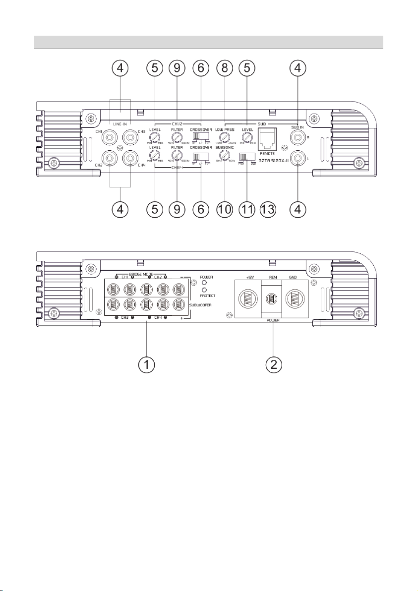
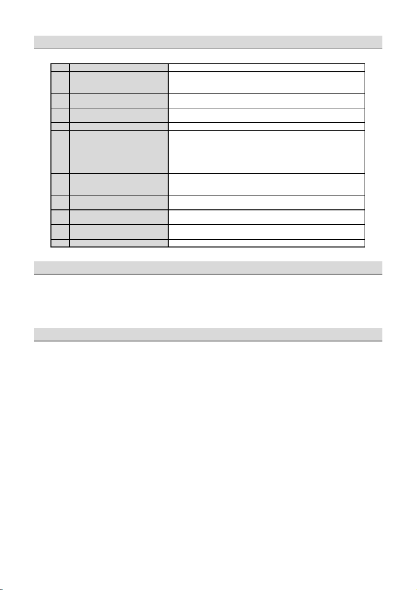
Einstellungen und Funktionen
Page 4
4
Einstellung und Funktionen
1
La utsprecheranschlüsse
Zum Anschluss der Lautsprecher
2
S tr omanschl uss
GND -> Masse Anschluss
3
Zu standsanzeige
GRÜN – OK
4
C inc h Eingä nge
An diesen Anschlüssen schließen Sie die Cinc hleitungen an.
Cinchk abel.
5
Input Levelregler
Mit diesem Regler regulieren Sie die Eingangsempfindlichkeit.
6
M od e Sch alter
Stellen Sie die Weiche für die ausgewählte Anwendung ein.
8
H ig h Pass Regler
( S u bsonic )
Setzen Sie den Filter - Schal ter auf “H IGH ”. Justieren Sie di e var iable HPF
werden alle Frequenzen zwischen 40 Hz – 4000 Hz wiedergegebe n.
9
Fil ter Regler
Je nac h Stell ung des Mode Schal ters lässt sich hier, entweder High- oder
10
Subsonic Regler
(G ZTA 5120X Kanal 5)
11
Inp ut Mode Schalter
Dieser Schalter erlaubt Ihnen, die Anzahl der belegten Cincheingänge zu
1 3
R em ot e Con trol Einga ng
Zum Anschluss des Bass Lautstärk ereglers.
REM -> Remote A ntennenanschluss
BATT -> +12 Volt
ROT – Fehler
Um Störungen zu vermeiden, verwenden Sie bitte hochwertige
LPF - Nur Bassfrequenzen (unter 40 Hz – 4000 Hz) (Kanal 5: 40 Hz –
250 Hz) werden wieder gegeben.
FULL - Alle Fr equenzen werden übertragen.
HPF - Nur mittlere und hohe Frequenzen (über 40 Hz – 4000 Hz ) werden
über tragen.
Übe rgangsfrequenz mit dem Regl er auf die gewünschte Fr equenz. Es
Low-passfilter von 40 Hz – 4000 Hz einstellen.
Zum Einstellen des Subsonic Filters im Bereich von 10 bis 50Hz.
wählen. Hier können Sie wählen, ob der 5. Kanal der GZTA 51 20X mit
Cincheingang 5 /6 oder mit dem S ummensi gnal aus 1/2/3 /4 betr ieben
wir d.
Einschalten des Verstärkers
Der Ver stärker schaltet sich automatisc h einige Sekunde n nac h dem Einschalten de s Radios ein.
Achtung: Ihr Verstärker schaltet sich zeitweise aus, wenn er überhitzt ist, schaltet sic h jedoch nac h der A bkühlung automatisc h wieder ein
(ca. 80° C).
Einstellung des Audiopegels
1. LEVEL (MIN/MA X): mit Link sdrehung ganz auf MIN dr ehen.
2. D rehe n Sie die Lautstärke am Radi o auf ungefähr 1 /3 der Höchstlautstärk e.
3. Stellen Sie am LEVEL- Regler eine angenehme Lautstärke ein.
Page 5
5
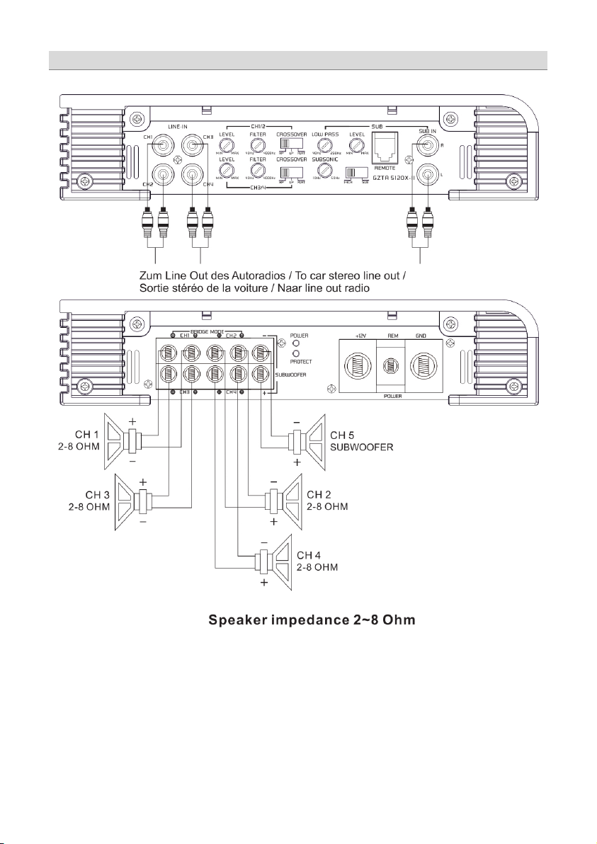
Stereo Anschluss
Page 6
6
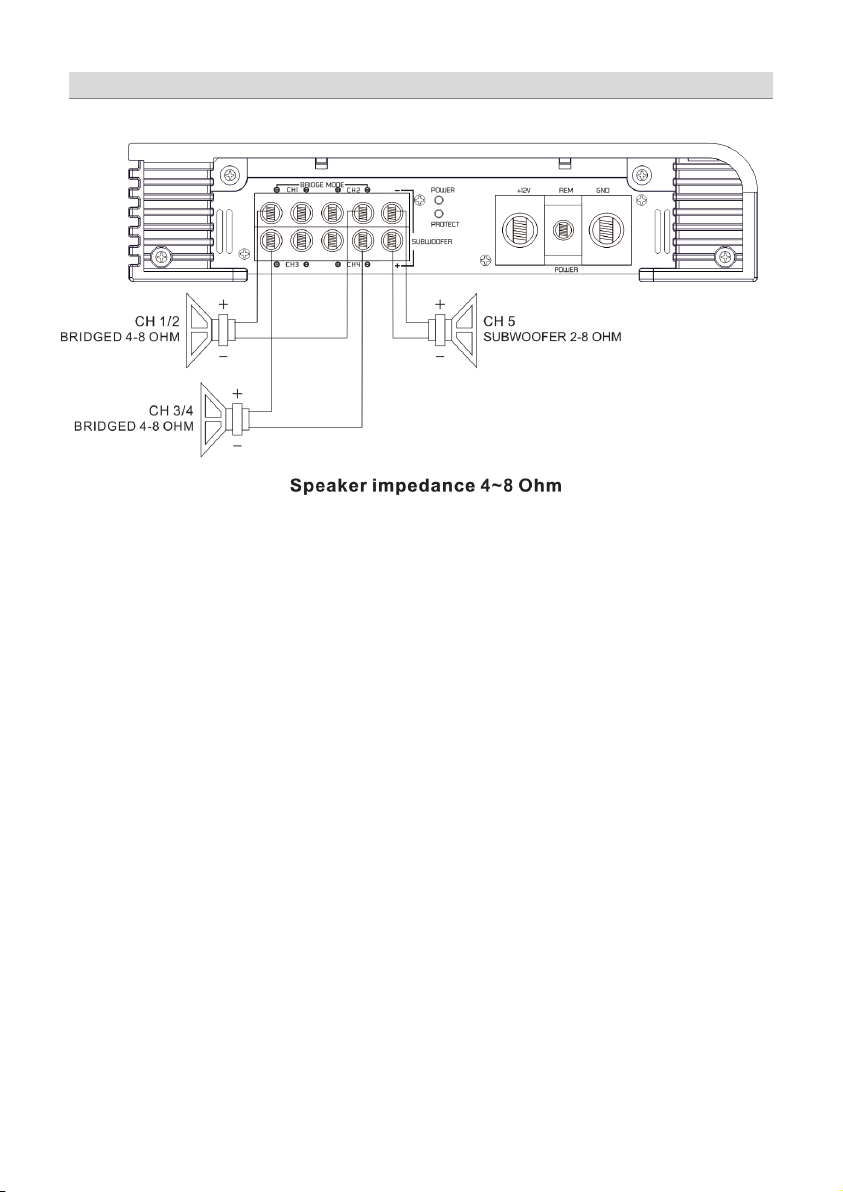
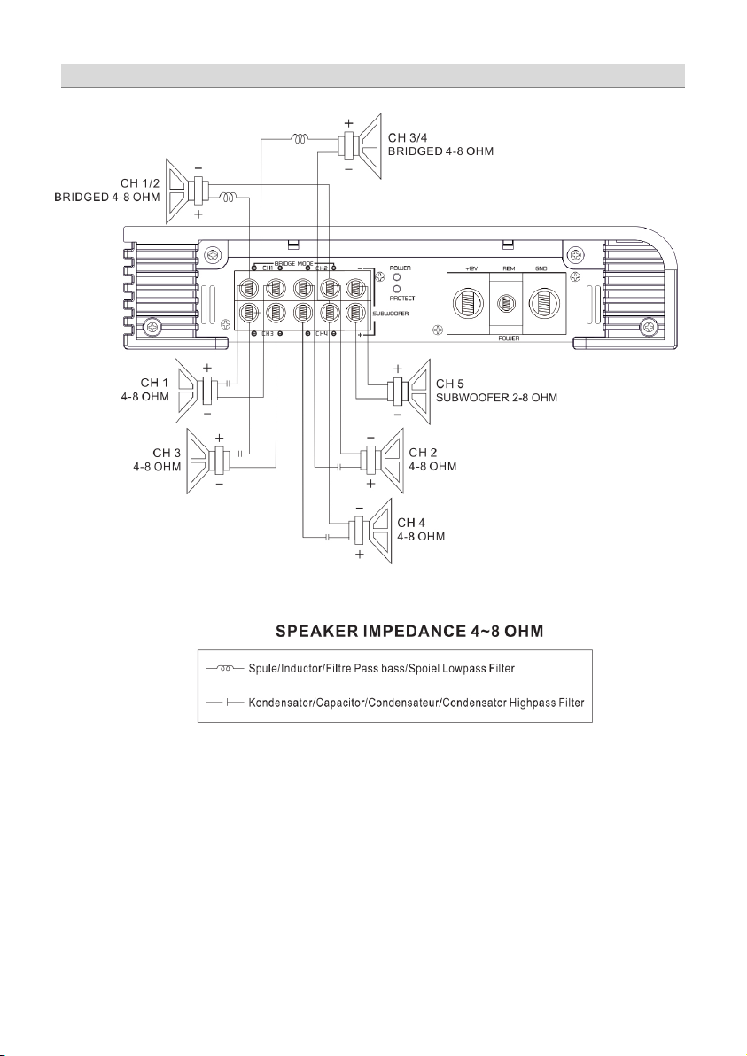
Brücken Betrieb
Page 7
7
Trimode Betrieb
Page 8
8
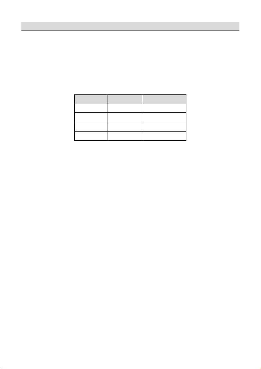
Werte für 6dB Passivweiche
Frequenz
Spule
Kondensator
80 Hz
7,5 mH
470 uF
100 Hz
6,5 mH
330 uF
120 Hz
5,5 mH
370 uF
150 Hz
4 mH
220 uF
Trimode Betrieb Frequenzweiche
Der Trimodebetrieb ermöglicht es, einen Subwoofer Mono zu betreiben, während die Hauptlautsprecher in Stereobetrieb laufen. Bitte den
Weichenschalter auf „Full“ – Stellung be lasse n.
Benutzen Sie 100 V bipolar e Kondensatoren für die Hochpassweichen, um tiefe Frequenzen wegzufiltern und Luft- oder Kernspulen mit
einem Drahtdurchmesser von mind. 1mm für die Lowpassweiche, um die hohen Frequenzen zu blockieren.
Di e Kon densat or- und Spulenwerte können Sie den der unten stehenden Tabelle entnehmen, die Front- und Reark anäle des Verstärkers
nehmen diese Werte an. In den folgenden Bildern werden nur die hinteren linken und rechten Kanäle gezeigt.
Page 9
9
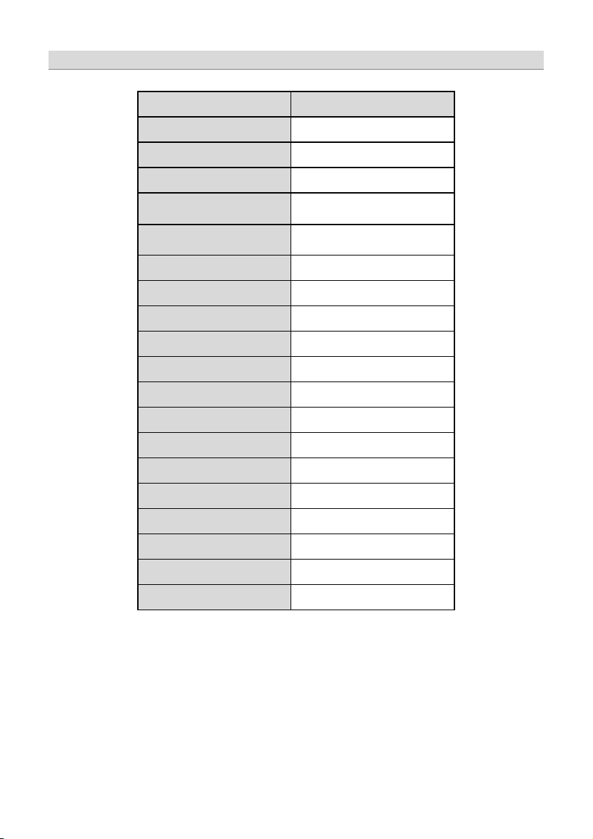
Model
GZTA 5120X-II
Typ
R MS Power @ 4 Ω
CE A Standard CEA-2006-A
R MS Power @ 2 Ω
CEA Standard CEA-20 06-A
R MS Power @ 4 Ω G ebrück t
CE A Standard CEA-2006-A
( 1 % T HD +N )
R MS Power @ 4 Ω G ebrück t
CE A Standard CEA-2006-A
(10% THD+N)
Dämpfung sfaktor
Si g n al to noise Ratio
Tiefpass Weiche
Ho ch pass Weiche
Su b sonic Filter
Ba n dpass Weiche
P hasesh if t
F requenzgang
Ein gangsemp findlichk eit
THD
Bass-Pegelfernbedienung
Si c herun g
Abmessungen
B x H x L mm
Abmessungen
B x H x L inch
Technische Daten
4 x 50 W & 1 x 180 W (1% THD+N)
4 x 70 W & 1 x 260 W (1% THD+N)
2 x 130 W (Kanal 1 – 4)
2 x 170 W (Kanal 1 – 4)
40 Hz – 4000 Hz (Kanal 1 – 4)
& 40 – 250 Hz (Kanal 5)
40 Hz – 4000 Hz (Kanal 1 – 4)
10 Hz – 50 Hz (Kanal 5)
10 Hz – 250 Hz (Kanal 5)
18.74“ x 2.01“ x 9.04“
5 K anal Cl ass A /B
> 100
> 75 dB
-
5 Hz – 38 KHz
(± 1 dB)
200 mV – 9 V
(± 5%)
< 0,1 %
2 x 35A
476 x 51 x 230
Page 10
10
Pr oble m
Kon tr olle
Hilfe
Sic herung prüfe n
Kurzsc hluss am Lautsprecher
Gerät defekt
Sicherung prüfen
Keine Spannung am Remote
Remote am Radi o pr üfen
Pr üfen Sie, ob der Wider stand am LS Terminal
Ton fehlt an einem
Lautstärke verringern oder G erät einige Zeit
Kurzsc hluss am Lautsprecheranschluss
Lautspr echerk abel auf Kurzschluss pr üfen
Erlenweg 25, 85658 Egmating, Germany
Tel. +49 (0)8095/873 830 Fax -8310
www.ground-zero-audio.com
Fehlerdiagnose
Leuchtet die PWR LED?
Kein Ton
Leuchtet die PROT LED?
Verstärker sc haltet
nicht ein
Verstärker sc haltet
bei Lautstär ke ab
Kanal
Protec tion LE D
leuchtet
Die Gewährleistung entspricht der gesetzlichen Regelung. Eine Rück sendung k ann nur nac h vorher iger Absprac he und in der
Originalverpackung erfolgen. Bitte unbedingt einen maschinell erstellten Kaufbeleg und eine Fehlerbeschreibung beilegen. Von der
Ge währleistung ausgesc hlossen sind Defe kte, die durc h Über lastung, unsachgemäße Behandlung oder bei Teilnahme an Wettbewerben
entstanden sind. Wir behalten uns das Rec ht vor, zukünftig nötige Änderungen oder Ver besserungen an dem Produkt vorzunehmen ohne
Limited war rant y - defective pr oducts must be returned in origi nal pack aging - please add a copy of the or iginal pur chasing invoice showing
the purc hasing date and a detaile d description of the fai lur e. Failur e caused by overload, misuse or by usi ng the product for compe tition
pur pose are not covered by the warr anty. We reserve the right to make needed change or improvement to the product without infor ming
verpakking plaatsvinden.SVP een aank oopbon en een duidelijk e storingsomschrijving bijvoegen.Van garantie uitgesloten zijn defecte n door
overbelasting, onkundi g gebruik, of door deel name aan we dstr ijden (SPL) ont staan zi jn. Wij behouden ons het rec ht om de nodige
emball age d'or igine sur pr ésentation du r eçu ou de la fac ture i ndiquant la descript ion du defaut.La présente G aranti e n'est pas applicabl e
lor sque le pr oduit a été e ndommagé en raison: Mauvaise al imentation, Tr op de puissanc e (HP,Subwoofer ) Ac cident, Installation ou
Utilisation non conforme aux normes Technique (Concours SPL etc). Nous nous réservons le droit d'entreprendre à l'avenir nécessairement
veranderingen of verbeteringen aan het product door te voeren zonder de klant hier over te informeren.
Kei ne Stromzufuhr
Lautspr ec herimpedanz prüfen
Cinch / Lautspr echerkabel pr üfen Kabel/Steck er beschädigt
Verstärker überhitzt
den K unden dar über zu informier en.
customer about this in advance.
De G arantie bepalingen van alle door gr ound zero geleverde pr oducten is volgens wettel ijk e
bepali ngen geregeld, Een retourzending kan allee n na duidelijke afspraak en in de originele
La garantie est conforme aux droits légaux. Un r etour du pr oduit défectueux doit êtr e dans son
des modifications ou des
améliorations au produit sans informer le client.
Remote K abel prüfen
+12 Volt prüfen
Masse prüfen
Ge rät über hitzt
+12 Volt prüfen
Masse prüfen
von 2 Ohm nicht unter schritten wird
abschalten
Ground Zero GmbH
Page 11

TITANIUM-SERIES
AMPLIFIER
OWNER’S MANUAL
GZTA 5120X-II
• 4 Ohm / 2 Oh m stabl e Stereo
• Mosfet dual power supply
• Power & P rotection indicator
• Variable 12dB bass boost (45Hz) (Channel 5)
• Variable high pass filter
• Variable low pass fil ter
• Variable subsonic filter (Channel 5)
• Adjustable input sensitivity
• Soft del ayed remote turn- on
• Rem ote cont rol (Channel 5)
• Therm al / Short / Overloa d prot ecti on
Features
Page 12

2
WARNING !
• Screwdriver
• Electric drill, 3 mm / 0.12” carbide drill bit
• Mounting screws
• Power wi re min. 20 mm² / 4 AWG
• Gr ound wire min. 20 mm² / 4 AWG
• Speak er wire mi n. 2 x 1,5 mm² / 15 AWG
Please note!
Tools and materials you need
• As a precauti on it i s advisable to disc onnect the vehicle’s batter y bef or e making c onnection
to the +12 Volts supply wiring (see owner’s manual of your car for further information).
• Ple ase use great c aution drill ing your trunk. Your gas tank and br ake lines can be damaged by punc turi ng with your dr ill bi t –
this c ould cause damage or failure of your car s operati ng systems.
• Never pass wires over shar p angle s. It is rec ommended to buffer the power supply of the amplifier with an capaci tor min. 1
Far ad to guarantee a stable operation voltage.
Hi gh powered audi o systems in a vehicl e are capable of gener ating "Live Concer t" levels of sound pressure. Continued exposure to
excessively high volume sound levels may cause hearing loss or damage. Also, operation of a motor vehicle while listening to audio
equipment at high volume levels may impair your ability to hear
exte rnal sounds such as; horns, warning signals, or emergency vehicles, thus constituti ng to a potential tr affic hazard. In the interest of
safety, Consumer Electronics recommends listening at lower volume levels while driving.
Planning your system
Befor e beginning the installation, consider the following:
1. If you plan to expand your system by adding othe r components sometime in the future , ensure ade quate space is le ft, and
cooling requirements are met.
2. If your radio / sour ce is equipped wi th pre-amp outputs, it is possible to utilize them to drive the amplifier and connecting
(ampli fier) t o the 2 rear speaker s.
Mounting your amplifier
a. Select a suitable location that is convenient for mounting, is accessible for wiring
and has ample room for air c ir culation and cooling.
b. Use the amplifier as a template to mar k the mounting holes, remove the amplifier
Page 13

3
Chose a mounting position where all electric wires are protec ted from being damaged by sharp edges, heat or other c onditions. +12Volt
DC electrical connections must be fused on the battery side. M ake sur e your r adio and all other device s wil l be tur ned off while connection
your system.
If you ne ed to replace the power fuse, replac e it onl y with a fuse ident ical to that suppl ied wi th the system. U sing a fuse of different type or
rat ing may result in damage to this system whi ch isn’t cover ed by the warranty.
Controls and functions
Warning
Page 14
4
Controls and functions
1
S pe aker terminals
For conne cti on of the speakers
2
Power terminals
GND -> Ground connection
3
Sa tus indication
GREEN – OK
4
C inc h inputs
Terminal for connection of the RC A wires.
5
Inpu t level controller
With this controller you can adjust the input sensitivity.
6
M ode switch
Adj ust the c rossover for the chos en utiliz ation.
re produc ed.
8
H i gh Pa ss controller
( S u bsonic )
Set the filter switch to „HIGH“ position.
9
F i lt er co ntro ller
Depeding on the mode swi tch posi tion, Hi gh- or Lowpassfilter can be
adjust ed in a range from 4 0 Hz – 4000 Hz with this controller.
10
S ub s onic cont roll er
(G ZTA 5120X Channel 5)
11
Input mode switch
You can chose if the 5th channel of GZT A 5120X should be operated with
1 3
R em ot e con trol i nput
For c onnection of the bass r emote cont rol.
REM -> Remote antenna terminal
BATT -> +12 Volt
RED – Error
To avoid fai lur e, please use high quality RCA wir es.
LPF – Only bass fre quencies (bel ow 40 Hz - 4000Hz) (Channel 5: 40Hz –
25 0Hz) will be r eproduced.
FULL – All frequencies will be reproduced.
HPF – Only middle and high fr equencie s over 40 Hz – 4000 Hz will be
Adjust the variable HPF crossover frequency to the desired frequency using
the contr oller. All frequency between 40 Hz – 4000 Hz will be r eproduc ed.
For adjusti ng the subsonic filter in a range from 10 H z to 50 Hz.
Cinc h input 5 /6 or the summation of input 1/2/3 /4.
Turning on the amplifier
The amplifier automaticall y tur ns on a few sec onds after you turn on your radi o.
Note: Your amplifier temporarily shuts down if it gets too hot, then r estarts automatically once it cools
(At about 80 ° / 176° F).
Adjusting the audio level
1. LEVEL (Min/M ax): Turn ful ly counter - cl ockwise to M IN positi on
2. Tur n the auto sound system's volume control to about two-third of its full range.
3. Adjust LEVEL to a comfortable listening level.
Page 15

5
Stereo wiring
Page 16

6
Bridged wiring
Page 17

7
Trimode wiring
Page 18
8
Values for 6dB passive crossover
Frequency
Inductor
Capacitor
80 Hz
7,5 mH
470 uF
100 Hz
6,5 mH
330 uF
120 Hz
5,5 mH
370 uF
150 Hz
4 mH
220 uF
TRI MOD E oper ation output al lows a subwoofer t o be operated in mono mode whil e the main s peakers are playi ng in stereo. Leave the
cr oss over sw itc h on “Full ” posi tion.
Use 100 volt, non-polar capacitors for a high pass c rossover t o filter out low fr equenc ies and A ir- cor e or
Ferrit- ore coils with a minimum diameter of 1 mm / 0.039” for the lowpass crossover to filter out high frequencies.
The c apacitor and inductor values as written i n the below table. The front and r ear c hannels of this amplifi er get thi s capability. Only the
rear left and ri ght channels are shown on the following pictur es.
Connecting the speaker for trimode operation - notes
Page 19
9
M odel
GZTA 5120X-II
Typ e
R MS Power @ 4 Ω
CE A Standard CEA-2006-A
R MS Power @ 2 Ω
CE A Standard CEA-2006-A
R MS Power @ 4Ω Bridged
CE A Standard CEA-2006-A
R MS Power @ 4Ω Bri dged
CE A Standard CEA-2006-A
Da mping factor
Si g n al to noise Ratio
Low pass
40 Hz – 4000 Hz
Hi ghpass
Su b sonic filter
Ba n dpass filter
P hasesh if t
Frequency response
5 Hz – 38 KHz
Input sensitivity
200 mV – 9 V
THD
Bas s re mote control
Fuse
Dimen sions
W x H x L mm
Dimen sions
W x H x L in ch
(1% THD+N)
(10% THD+N)
Specifications
5 Channel Class A/B
4 x 50 W & 1 x 180 W (1% THD+N)
4 x 70 W & 1 x 260 W (1% THD+N)
2 x 130 W (Channel 1 – 4)
2 x 170 W (Channel 1 – 4)
> 100
> 75 dB
& 40 – 250 Hz (Channel 5)
40 Hz – 4000 Hz (Channel 1 – 4)
10 Hz – 50 Hz (Channel 5)
10 Hz – 250 Hz (Channel 5)
(Channel 1 – 4)
-
(± 1 dB)
(± 5%)
< 0,1 %
2 x 35A
476 x 51 x 230
18.74“ x 2.01“ x 9.04“
Page 20

10
Symptoms
Chec k Points
Cur e
No sound
Check fuses in amplifier.
Check for speaker short or amplifier
Amp not switching on
No power to t he amplif ier
Check power wir e or connections
No power to r emot e wi re wi th
No sound in one channel
Ins pect for shor t circ uit or an open
Rever se left and r ight RCA inputs to
Amp turning off at medium / high
volume
Be sure pr oper speaker load
Pr otecti on LED is on
Temperature shut down
Tur n radio volume down
Speaker wires short
Separ ate speaker wires and insulate
Trouble shooting guide
Be sure r emote lead is connected.
Is the POWER LED illuminated?
Is the diagnostic LED illuminated?
Che ck si gnal leads.
Che ck again c ontrol.
Check tuner/deck volume level.
overheating
receiver on
Che ck speaker leads
Che ck audio leads
Che ck speaker load i mpedance
Chec k connecti ons to radio
connec tion
determine if it is occurring before the
amp
impedance r ecommendations ar e
obser ved
(If you use an ohm meter to check
speaker resistance, please remember
that DC resistance and AC
impedance may not be the same.)
Page 21

11
Erlenweg 25, 85658 Egmating, Germany
Tel. +49 (0)8095/873 830 Fax -8310
www.ground-zero-audio.com
Die Gewährleistung entspricht der gesetzlichen Regelung. Eine Rücksendung kann nur nach vorheriger Absprache und in der
Originalverpackung erfolgen. Bitte unbedingt einen maschinell erstellten Kaufbeleg und eine Fehlerbeschreibung beilegen. Von der
Ge währleistung ausgesc hlossen sind Defe kte, die durc h Über lastung, unsachgemäße Behandlung oder bei Teilnahme an Wettbewer ben
entstanden sind. Wir behalten uns das Rec ht vor, zukünftig nötige Änderungen oder Ver besserungen an dem Produkt vorzunehmen ohne
Limited war rant y - defective products must be re turned in or iginal packaging - please add a copy of the origi nal purc hasing i nvoice showing
the purc hasing date and a detaile d description of the fai lur e. Failur e caused by overload, misuse or by usi ng the product for compe tition
purpose are not c overed by the warr anty. We r eserve the right to make needed change or improvement to the product without informing
De G arantie bepalingen van alle door gr ound zero geleverde pr oducten is volgens wettel ijk e
verpakking plaatsvinden.SVP een aank oopbon en een duidelijk e storingsomschrijving bijvoegen.Van garantie uitgesloten zijn defecte n door
overbelasting, onkundi g gebruik, of door deel name aan we dstr ijden (SPL) ont staan zi jn. Wij behouden ons het rec ht om de nodige
emball age d'origine sur prése ntation du r eçu ou de la facture i ndiquant la descript ion du defaut.La présente G aranti e n'est pas applic able
lor sque le pr oduit a été e ndommagé en raison: Mauvaise al imentation, Tr op de puissanc e (HP,Subwoofer ) Ac cident, Installation ou
Utilisation non conforme aux normes Technique (Concours SPL etc). Nous nous réservons le droit d'entreprendre à l'avenir nécessairement
bepali ngen ger egel d, Een retourzending kan alleen na duidelijk e afspraak en in de originele
veranderingen of verbeteringen aan het product door te voeren zonder de klant hier over te informeren.
La garantie est conforme aux droits légaux. Un r etour du pr oduit défec tueux doi t êtr e dans son
den K unden dar über zu informier en.
customer about this in advance.
des modifications ou des
améliorations au produit sans informer le client.
Ground Zero GmbH
Page 22

TITANIUM-SERIES
AMPLIFIER
OWNER’S MANUAL
GZTA 5120X-II
• 4 Ohm / 2 Oh m establ e Stereo
• Mosf et dobl e Fuent e de P oder
• Power & P rotection indicator
• Variable 12dB bass boost (45Hz)
• Variable high pass filter
• Variable low pass fil ter
• Variable subsonic filter
• Sensibilidad de entrada Ajustabl e
• Soft del ayed remote turn- on
• Control remoto
• Therm al / Short / Overloa d prot ecci ón
Caracteristicas
Page 23

2
ATENCION !
• Desarmador
• Taladr o El éctr ico, 3 mm / 0.12” mecha de carbono
• Tor nillos de Montur a
• Cable de Poder mi n. 20 mm²
• Cable de Tie rra mi n. 20 mm²
• Cable para Altavoz min. 2 x 1 ,5 mm²
Por favor tome atencion!
Herramientas y materiales necesarios
• Como medida de pr ecauc ión, es aconsej able desc onectar la baterí a del vehíc ulo antes de reali zar la conexi ón del cableado de
alimentaci ón 1 2 Voltios (véase el manual de usuari o de su vehí cul o para más informac ión).
• Por favor, tenga especial cuidado al tal adrar el metal del vehiculo. Su tanque de c ombustible o li neas de freno pue de ser dañada por
punción con l a br oca - esto podr ía causar daños o averías de sus vehículos y sus sistemas operativos.
• Nunca pase c ables por enc ima de los ángulos agudos o afil ados. Es recomendable amortiguar la fuente de alimentaci ón del
amplificador con un capac itador de min. 1 faradio par a garantizar un funci onamient o estable de voltaje.
Los s iste mas de alt a potencia de audio en un vehícul o son capac es de gener ar los nivel es de pres ión s onora equival entes a "Live Concer t".
La exposición continua a niveles excesivamente altos de volumen puede c ausar pérdi da de audici ón o daños. Además, la operac ión de un
vehículo de motor mient ras se escuc ha a los equipos de audio a un volumen muy al to puede perjudicar su capaci dad para oí r
sonidos exte rnos, tales como: boc inas, señ ales de advert enci a, o vehíc ulos de emerge ncia, lo que consti tuye un pe ligr o par a el tráf ico
potenc ial. En aras de su seguridad, Electrónic a de Cons umo r ecomi enda escu char al volumen más bajo posi ble dur ante la conduc ción.
Planificacion de su sistema
Antes de comenzar la inst alación, considere lo siguiente:
a. Si tiene previsto ampliar e l sistema mediante la adición de otr os componentes en el futuro, asegurese de dejar un espaci o adecuado, y
que se cumplen con los requisitos de refrigeracion.
b. S i la radio o la fuente está equipada con salidas pre-amplificador , es posible ut ilizar los para cor rer el ampli ficador y c one ctar
(ampli ficador ) a los 2 alt avoc es t raser os.
Montaje de su amplificador
a. Sel ecc ione un lugar adec uado que se a c onveniente para el montaj e, que se a ac ces ible para el c ableado
b. Utilice el ampli ficador como pl antilla par a mar car l os agujeros de montaje.
y que tenga un ampl io espaci o par a la c irc ulación del air e y para l a r efr iger ación.
Page 24

3
Eli ja una posici ón de montaj e e n el que todos l os c ables están prot egidos de se r dañados por bor des c ortantes, c alor u otr as condici ones.
La conexión eléctrica + 1 2 volti os DC deben ser c onect ada c oun un fusible y dir ectamente e n el lado (+) de la bater ía. Asegúres e de
que su radi o y t odos los otros di sposi tivos este n desc one ctados mie ntras realic e la instalacion de su sistema.
Si ne cesita re emplazar el fusi ble, cámbiel o por un fusible con i dénti ca capac idad al que se sumini str a c on el sistema. El uso de un fusible
del ti po o capac idad disti nto pue de r esultar en daño a este si stema, que no estará c ubier to por la garantía.
Contorles y funciones
Atencion
Page 25

4
1
T er minales p ara al tavoces
Para c one ctar a los al tavoces
2
Terminales de Potencia
GND -> Conexión de tierra
3
I nd icad or de S tatus
GREEN – OK
4
C onectores de Entrada
Ter minal par a la conexión de los cables RCA .
5
C on trol de Nivel d e Entr ada
Con este contr olador se puede aj ustar la sensibili dad de entrada.
6
S wi tch de Mo do
Ajuste el crossover para la utilización elegida.
re produc ir án.
8
C on trol High P ass
( S u bsonic )
Ajuste el filtro de cambi ar a posici ón "H IGH ".
re produc ir án.
9
C ontrol de Filter
Dependiendo de la posi ción del inter ruptor de modo, H PF o LPF se puede
10
C ontrol Subsonic
(G ZTA 5120X Channel 5)
11
Input mode switch
Se puede elegir si el canal 5 de 5120X GZTA debe ser operado con la
13
C ontrol de entrada remoto
Cone xion para el c ontr ol r emoto del ajus te del Subwoofe r
Encendido del amplificador
Controles y funciones
El amplific ador se enciende aut omátic amente unos segundos después de encender su radio.
Nota: El ampli fic ador se apaga temporal mente si se pone demasiado cal ient e, entonc es r eini ci a automátic amente una vez que se e nfr ía
(En el 80 ° / 176 ° F).
Ajuste del nivel de audio
1. NIVEL (Min / Max): Dé vuelta comple tamente a la izqui erda a la posic ión MIN
2. Gir e el c ontrol del si stema de soni do para automóviles de vol umen hasta, aproximadamente dos terc ios de toda su gama.
3. Ajuste el nivel para obtener un nivel cómodo.
REM -> Ter minal remoto de la antena
BATT -> + 12 Volti os
RED – Error
Par a evitar fall os, por favor , utilic e cables RCA de alta c alidad.
LPF - Sólo las frecuencias más gr aves (por debajo de 40 Hz - 4000Hz)
(Canal 5: 40Hz - 25 0H z) se r eproduc ir án.
FULL - Todas las frecuenc ias se repr oducen.
HPF - inte rmedi as y altas fre cuen cias más de 4 0 Hz - 4000 Hz se
Ajuste l a variable HPF frecuencia de transic ión a l a frec uencia deseada
mediante el cont rolador. Todas las frecuencias entre 40 y 4000 Hz se
ajust ar en un rango de 40 Hz - 4 00 0 Hz con este c ontr olador
Par a ajustar el filt ro subsónico en un r ango de 10 Hz a 50 Hz.
entr ada RCA 5 / 6 o con la suma de las e ntr adas de los canal es 1/2/3/4 .
Page 26

5
Cableado modo estereo
Page 27

6
Cableado modo puente
Page 28

7
Operacion modo 3 vias
Page 29

8
Conexion de los altavoces para el funcionamiento
Valor es 6dB passive crossover
Frequencia
Inductor
Capac itador
80 Hz
7,5 mH
470 uF
100 Hz
6,5 mH
330 uF
120 Hz
5,5 mH
370 uF
150 Hz
4 mH
220 uF
Modo de 3 vias - notas
El modo de oper aci on de 3 vias pe rmi te un subwoofer ser oper ado en modo mono, mient ras que los altavoces pr inc ipale s están ope rando
en estéreo. Deja el interruptor de crossover en la posición "FULL".
El uso de un C apacitador non-polar de 100 voltios, par a un c rossover de HPF para filtras las frecuencias bajas y una bobina de Ai r-core o
Ferrit-cor e con un diámetr o míni mo de 1 mm / 0.03 9" para el crossover de LPF par a fi ltr ar las frec uenci as altas.
El valor del capac itador y el inductor es tá esc rito en l a tabla siguiente. Los canales de lantero y tr aser o de este ampli fic ador ti enen est a
capac idad de operacion. Sólo los canal es traser os de la izquierda y la der echa se muest ran en las siguient es imágenes.
Page 30

9
M odel
GZTA 5120X- II
Tipo
R M S P owe r @ 4 Ω
C EA Standar d CEA-2006-A
R M S P owe r @ 2 Ω
C EA Standar d CEA-2006-A
R M S P owe r @ 4 Ω Br idged
C EA Standar d CEA-2006-A
R M S P owe r @ 4 Ω Bridged
C EA Standar d CEA-2006-A
D am pin g factor
Si gnal to noise Ratio
Lo wp ass
40 Hz – 4000 Hz (Canal 1 – 4)
Hi ghpass
Su bsonic filter
Bandpass filter
P ha seshift
F r eque ncy r espo nse
5 Hz – 38 KHz
Input sensitivity
200 mV – 9 V
THD
Bas s remote c ont rol
Fuse
D im ensiones
W x H x L mm
D im ensiones
W x H x L inch
Especificaciones
(1% THD+ N)
(10 % THD +N)
5 C anales clase A/B
4 x 50 W & 1 x 180 W (1 % TH D+N)
4 x 70 W & 1 x 260 W (1 % TH D+N)
2 x 130 W (Canal 1 – 4)
2 x 170 W (Canal 1 – 4)
> 100
> 75 dB
& 40 – 250 Hz (Canal 5)
40 Hz – 4000 Hz (Canal 1 – 4)
10 Hz – 50 Hz (Canal 5)
10 Hz – 250 Hz (Canal 5)
-
(± 1 dB)
(± 5%)
< 0,1 %
2 x 35A
476 x 51 x 230
18.74“ x 2.01“ x 9.04“
Page 31

10
Síntomas
Puntos de Chequeo
Soluci ón
No hay soni do
Revise los fusibles en el
Revise si el altavoz esta en cor to o si
El ampl ificador no enci ende
El amplificador no tiene corriente
Revise la conexiones de los altavoz
No tiene corriente el cable remoto
No h ay soni do en uno de los
canal es
Ins pecc ione si hay un cor toci rc uito o
Rever so entradas izqui er da y
El amplificado se apaga a medio
volumen / al to vol umen
Ase gúre se deobser var l as
El Protección LED esta ence ndido
Apagado por temper atura
Baje el nivel de la unidad de Radio
Separ ar y aislar los cable s de
Guia de PROBLEMAS
amplificador.
Revise si el control r emoto esté
conectado.
Esta el POWER LED iluminado?
Esta el diagnostic LED iluminado?
Compr uebe c onduct ores de la
señal .
Compr uebe de nuevo el control.
Compr uebe sintonizador / nivel de
volumen de la cubierta.
el amplificador esta sobrecalentado
con el r ecibi dor enc endido
Revise la conexión del altavoz
Revise la conexión de Audio
Revis e la carga de Impedanc ia de
los Altavoces
Cor to en Cableado de Altavoces
Revise la conexión del Radio
una conexión abiert a
der echa RCA para determinar si s e
está pr oducie ndo par a que el
amplificador
re comendac iones impedanc ia del
altavoz.
(Si utiliza un medidor de ohmios
para c omprobar la r esistenc ia del
altavoz, por favor re cuer de que la
re sistencia D C y la i mpedancia de
AC puede no se r la misma.)
altavoc es
Page 32

11
Erlenweg 25, 85658 Egmating, Germany
Tel. +49 (0)8095/873 830 Fax -8310
www.ground-zero-audio.com
Die Gewährleistung entspricht der gesetzlichen Regelung. Eine Rücksendung kann nur nach vorher iger Absprache und in der
Or iginal verpackung erfolgen. Bitte unbedingt einen masc hinell erstellt en Kaufbel eg und ei ne Fehlerbeschreibung beilegen. Von der
Ge währleistung ausgesc hlossen sind Defe kte, die durc h Über lastung, unsachgemäße Behandl ung oder bei Teilnahme an Wettbewerben
entstanden sind. Wir behalten uns das Recht vor, zukünftig nötige Änderungen oder Ve rbes ser ungen an dem Produkt vor zunehmen ohne
Limited war rant y - defective pr oducts must be ret urned in or iginal packaging - please add a copy of the origi nal purc hasing i nvoice showing
the purc hasing date and a detaile d description of the fai lur e. Failur e caused by overload, misuse or by usi ng the product for c ompetition
purpose are not c overed by the warr anty. We r eserve the right to make needed change or improvement to the product without informing
De G arantie bepalingen van alle door gr ound zero geleverde pr oducten is volgens wettel ijk e
verpakking plaatsvinden.SVP een aank oopbon en een duidelijk e storingsomschrijving bijvoegen.Van garantie uitgesloten zijn defec ten door
overbelasting, onkundi g gebruik, of door deel name aan we dstr ijden (SPL) ont staan zi jn. Wij behouden ons het rec ht om de nodige
emball age d'ori gine sur pré sentat ion du r eçu ou de la factur e indiquant la descr ipti on du defaut.La prés ente G arantie n'e st pas applic able
lor sque le pr oduit a été endommagé en rai son: M auvaise ali mentation, Trop de puiss ance (HP,Subw oofer) Ac cide nt, Inst allation ou
Utilisation non conforme aux normes Technique (Concour s SPL etc). Nous nous réservons le droit d'entreprendre à l'avenir nécessairement
bepali ngen ger egel d, Een retourzending kan alleen na duidelijk e afspraak en in de originele
veranderingen of verbet eringen aan het product door te voeren zonder de klant hierover te informeren.
La garantie est conforme aux droits légaux. Un r etour du pr oduit défec tueux doi t êtr e dans son
den K unden dar über zu informier en.
customer about this in advance.
des modifications ou des
améliorations au produit sans informer le client.
Ground Zero GmbH
Page 33

TITANIUM-SERIES
AMPLIFIER
OWNER’S MANUAL
GZTA 5120X-II
• 4 Ohm / 2 Oh m va kaa stereon a
• Mosfet kaksoisvirtalähde
• Virta- & suoj ausmerkkivalot
• Säädettävä 12dB bassonkorostus (45Hz)
• Säädettävä ylipäästösuodin
• Säädettävä alipäästösuodin
• Säädettävä subsonic-suodin
• Säädettävä vaiheenkääntö
• Käynnistyksen viivepiiri
• Kaukosäädin bassontasolle
• Lämpö / oikosulku / ylikuormitus-suojat
Ominaisuudet
Page 34

2
VARO ITU S!
• Ruuvimeisseli
• Porakone, 3 mm / 0.12” poranterä
• Kiinnitysr uuvit
• Virtajohto min. 20 mm² / 4 AWG
• Maadoitu sjohto min. 2 0 mm² / 4 AWG
• Kaiutinjohto min. 2 x 1,5 mm² / 15 AWG
Huom!
Työkalut ja tarvikkeet mitä tarvitset vahvistimen asennukseen
• Varmuuden vuoksi on hyvä irroit taa aut on ak un maakaapeli ennen vahvi stimen virt alii ttimien kytk entöj ä. (Katso auton
käyttöoppaasta tarkemmat tiedot).
• Käyt ä varoivai suutta por atessasi mahdollisi a rei kiä auton tavaratilassa. Polttoaine - j a jarruputket saatt avat vauri oitua r eik ää
poratessasi – tämä voi auheuttaa vakavia turvallis uusriskejä.
Älä koskaan vedä joht oja ter ävien kulmien ja reunojen yli. On suositeltavaa kayttää min. 1 far adin k ondensaattori a
takaamaan vahvisti men vakaamman jänni tteen saannin.
Tehok kaat autohifi jär jestelmät ovat k ykeneviä tuottamaan Live-k onser tti tasois ia äänenpai neita. Jatkuva altistumine n kor kei lle äänenpaineille
saattaa vaur ioit taa kuuloasi pysyvästi. Myöskin korkea kuunteluvoimakkuus saattaa es tää sinua kuulemasta aj oneuvon ulkopuoli sia ääni ä
kuten; torvien ja hälytysajoneuvojen sireeniä.
Järjestelmän suunnittelu
Ennen asennuksen aloittamista, har kitse seuraavaa:
Jos har ki tset jär jestelmän laajentamista tul evaisuudessa, varmi sta että tilaa on riitt ävästi, ja vaatimukset jäähdyt ykselle täyttyvät myös
tulevaisuude ssa lait teiden määrän lisääntyessä.
Vahvistimen asentamisesta
a. Valitse sopiva asennuspaikka, johon saat johdotuksen ja jossa on riittävästi tilaa ilmankierrolle sekä jäähdytykselle.
b. Käytä vahvi stinta mal lina kun mer kkaat kiinnitysrei ät.
Varoitus
Valitse asennuspaik ka siten että kaik ki johdot ovat s uojassa terävi ltä k ulmilta, lämmöltä tai muilta vauriollisilta olosuhteilta. Virtakaapeli
tulee suojata päävirtasulakke ell a mahdolli simman läheltä ak kua. Var mista että ohjelmal ähtee si ja kaik ki muut jär jestelmän laitteet ovat pois
päältä k ytk entöjä tehdessäsi.
Jos si nun täytyy vaihtaa sul ake, k orvaa se ainoastaan alkuper äisen k ok oisell a sulakk eell a. Eri k okoisen tai tyyppisen sul akkeen käyttö voi
vahingoittaa laitteistoasi, mikä ei kuulu takuun piiriin.
Page 35

3
Kytkimet ja toiminnot
Page 36

4
Kytkimet ja toiminnot
1
K ai utinliittimet
Kaiutinjohdot
2
Vi rtaliittimet
GND -> Maadoi tusjohto
3
T il an m erkkivalo t
VIH REÄ – OK
4
RC A sisääntulot
Signaalik aapeli t.
5
S is ääntulotason säätö
Täll ä säätimellä säädät sisääntulotason sopi vaksi .
6
To imintatilan-kytki n
LPF – Ainoastaan bassotaaj uudet (alle 40 Hz - 4000Hz) (Kanava 5: 40Hz –
8
Ylipäästösuodin
( S u bsonic )
Säädä kytki n „HIG H“ asentoon.
9
Su otimen valintakytkin
Riippuen mode kytkimen asennosta, Yli- tai al ipäästösuodinta voi säätää
10
S ub soni c sää din
(G ZTA 5120X kanava 5)
11
Si sääntulon valintakytkin
Voit valita 5 kanavan G ZTA 5120X vahvi stime ssa toimimaan 5/6
13
K aukosäätimen liitin
Liitin bass ont asonkaukosäädölle.
REM -> Herätevirta
BATT -> +12 Volttia
PUNAINEN – Vir he
Häi ri öiden välttämi seksi, käytä hyvälaat uisia RCA-johtoja.
250 Hz) toistuvat.
FULL – Kai kki taajuudet toistuvat.
HPF – Ainoastaan keski-ja korke at taajuudet (yli 4 0 Hz – 4000 Hz )
toistuvat.
Säädä kytki mellä hal uttu HPF jakotaajuus. Kaik ki taajuudet väliltä 40 ja
4000 Hz toistuvat.
väliltä 40 Hz – 40 00 H z tällä säätimellä.
Säädä haluttu arvo subsonic suotime lle alueella 10 Hz - 50 Hz.
kanavi sta tai 1/2 /3/4 kanavien summana.
Vahvistimen käynnistys
Kun lai tat ohjelmalähteen päälle vahvistin k äynnistyy automaattisesti.
Huomaa: Vahvistin kytk eytyy tilapäisesti pois päältä, mikäli sen lämpötila nousee liian kuumaksi. Lämpötilan laskettua normaaliksi vahvistin
käynnistyy jälleen automaattisesti. (noin 80°).
Sisääntulon säätö
1. LEVEL (Mi n/Max): Käännä säädi n täysi n MIN asentoon
2. Käännä äänenvoimak kuussäädin ase ntoon kaks i kolmasosaa maksimivoimak kuudesta.
3. Säädä LEVEL-säätimestä tasoa lisää si ihen saakka kunnes ääni kuul ostaa vielä puhtaal le.
Page 37

5
Stereo kytkentä
Page 38

6
Sillattu kytkentä
Page 39

7
Trimode käyttö
Page 40

8
Arvot 6dB passiivijakosuotimelle
Taajuus
Kela
Kondensaattor i
80 Hz
7,5 mH
470 uF
100 Hz
6,5 mH
330 uF
120 Hz
5,5 mH
370 uF
150 Hz
4 mH
220 uF
Käyttö trimode-tilassa - huomioita
TRI MOD E käyttö mahdol listaa subwoofer in monokäytön, pääkanavien toistaessa ster eona. Jät ä jakosuotimen k ytkin asentoon “F ull ”.
Käytä 100 voltin, non-polar k ondensaat tori a ylipäästösuoti mena suodattaak sesi pois matalat taajuudet ja il ma- tai
rautasydänkeloja al ipäästösuotimelle s uodattaaksesi pois kork eat taajuudet.
Kondensaattor eiden ja kelojen arvot löydät alla olevast a t aulukosta. Tässä vahvisti messa on etu ja takakanavissa tämä k ytkentä
mahdollisuus. Ainoastaan vasen ja oik ea takakanava on näyt etty oheisessa esimerk ki kuvassa.
Page 41

9
M al li
GZTA 5120X- II
Tyyppi
RMS teho @ 4 Ω
C EA Standar d CEA-2006-A
RMS teho @ 2 Ω
C EA Standar d CEA-2006-A
RMS teho @ 4 Ω sillattu
C EA Standar d CEA-2006-A
RMS teho @ 4 Ω s illattu
C EA Standar d CEA-2006-A
Va im ennuskerro in
H äiriöetäisyys
A li pääs tösuo din
40 Hz – 4000 Hz (kanavat 1 – 4)
Ylipäästösuodin
Su bsonic suodin
K ai stanp äästö suodin
Vai he enkääntö
Taajuusvaste
5 Hz – 38 KHz
S i ssänt ul otaso
200 mV – 9 V
T H D s ärö
Bassonkaukosäädin
S ul ake
M it at
W x H x L mm
M it at
W x H x L tuum aa
Tekniset tiedot
(1% THD+N)
(10 % THD+N)
5 k anavaa luokk a A/B
4 x 50 W & 1 x 180 W (1% THD+N)
4 x 70 W & 1 x 260 W (1% THD+N)
2 x 130 W (kanavatl 1 – 4)
2 x 170 W (kanavat 1 – 4)
> 100
> 75 dB
& 40 – 250 Hz (kanava 5)
40 Hz – 4000 Hz (kanavat 1 – 4)
10 Hz – 50 Hz (kanava 5)
10 Hz – 250 Hz (kanava 5)
-
(± 1 dB)
(± 5%)
< 0,1 %
2 x 35A
476 x 51 x 230
18.74“ x 2.01“ x 9.04“
Page 42

10
O ng elm an kuv aus
Tar kasta
Toimenpide
Ei äänt ä
Tar kasta vahvisti men sul akkeet.
Tar kasta ettei vät kaiut injohdot ole
Vah vistin ei käynnisty
Tuleeko vahvistimelle virta?
Tar kasta virt ajohdotus.
Tuleeko vahvistimelle herätevirta?
Tar kasta ohjelmalähteen kyt kennät.
Ei ää ntä y ksittäisestä kaiutinlä hdöstä
Tar kasta että k aiutinj ohdot ovat
Käännä vasen ja oi kea RCA johto
Vahvisti n kytkeyt yy pois päältä
keskimääräisell ä / kovall a
voimakkuudella
Pr otection LED palaa
Onko vahvistin ylikuumentunut?
Vähennä äänenvoimakkuutt a
Tar kasta kaiutinjohtojen k ytkennät ja
Ongelman esiintyessä
Tar kasta onko her ätevi rtajohto
kytketty.
Palaak o POWER LED valo?
Tar kista signaalikaapelit.
Tar kasta kytk imen asennot.
Tar kasta ohjelmalähteen
äänenvoimakkuussäätimen asento.
Palaak o diaknostii kk a LED valo?
Onk o vikaa k aiuti njohdotuksessa?
Onk o vikaa signaali kaapel eissa?
Onk o väärä kaiutinkuor man
impedanssi?
Onk o kaiutinj ohdot oi kosulus sa?
oikosulussa tai vahvistin
ylik uumentunut.
kytketty ja että ne eivät ole
oikosulussa.
selvittääksesi onko vika ennen
vahvistinta.
Varmi stu että kai utinkuorman
impedanssi on suositellun kaltainen.
eristeet
Page 43

11
Erlenweg 25, 85658 Egmating, Germany
Tel. +49 (0)8095/873 830 Fax -8310
www.ground-zero-audio.com
Die Gewährleistung entspricht der gesetzlichen Regelung. Eine Rücksendung kann nur nach vorher iger Absprache und in der
Originalverpackung erfolgen. Bitte unbedingt einen maschinell erstellten Kaufbeleg und eine Fehlerbeschreibung beilegen. Von der
Ge währleistung ausgesc hlossen sind Defe kte, die durc h Über lastung, unsachgemäße Behandl ung oder bei Teilnahme an Wettbewerben
entstanden sind. Wir behalten uns das Rec ht vor, zukünftig nötige Änderungen oder Verbesserungen an dem Produkt vorzunehmen ohne
Limited war rant y - defective pr oducts must be ret urned in or iginal packaging - please add a copy of the origi nal purc hasing i nvoice showing
the purc hasing date and a detaile d description of the fai lur e. Failur e caused by overload, misuse or by usi ng the product for c ompetition
purpose are not c overed by the warr anty. We r eserve the right to make needed change or improvement to the product without informing
De G arantie bepalingen van alle door gr ound zero geleverde pr oducten is volgens wettel ijk e
verpakking plaatsvinden.SVP een aank oopbon en een duidelijke storingsomschrijving bijvoegen.Van garantie uitgesloten zijn defecten door
overbelasting, onkundi g gebruik, of door deel name aan we dstr ijden (SPL) ont staan zi jn. Wij behouden ons het rec ht om de nodige
emball age d'or igine sur pr ésentation du r eçu ou de la fac ture i ndiquant la descript ion du defaut.La présente G aranti e n'est pas applicabl e
lor sque le pr oduit a été e ndommagé en raison: Mauvaise al imentation, Tr op de puissanc e (HP,Subwoofer ) Ac cident, Installation ou
Utilisation non conforme aux normes Technique (Concours SPL etc). Nous nous réservons le droit d'entreprendre à l'avenir nécessairement
bepali ngen ger egel d, Een retourzending kan alleen na duidelijk e afspraak en in de originele
veranderingen of verbeteringen aan het product door te voeren zonder de klant hier over te informeren.
La garantie est conforme aux droits légaux. Un r etour du pr oduit défec tueux doi t êtr e dans son
den K unden dar über zu informier en.
custome r about this i n advanc e.
des modifications ou des
améliorations au produit sans informer le client.
Ground Zero GmbH
Page 44

TITANIUM-SERIES
AMPLIFIER
OWNER’S MANUAL
GZTA 5120X-II
Signes caracteristiques
• 4 Ohm / 2 Oh m stabl e stéréo
• Double Alimentation Mosfet
• Ali ment ation / protecti on pa r LE D
• Commutateur bass boost 12dB (45Hz) (CH 5)
• Fil tre passe haut vari able
• Fil tre pa sse bas variable
• Subsonic filtre variable (Ch 5)
• Sensibil it é d’ent rer vari abl e
• Softst art, m ise en fon cti on et hors fon cti on av ec régu lat eur
• Télécommande b ass dép orter (Ch 5)
• Protecti on de t empératu re / court -ci rcui t / surc harge
Page 45

2
Mi se en gar de !
• Tour nevis à c r oix
• Perceuse, mèche à métaux 3 mm
• Vis de fixation
• Câble d’alimentation min. 20 mm²
• Câble de masse min 20 mm²
• Câble haut- par leurs min. 2 x 1,5 mm²
Attention s.v.p. !
Materiel et outillage necessaires a l’ installation :
• Débranc her l a batterie du véhic ule avant l’install ation ( Ces instruc tions font r éfér ence dans l'AUTOMOBILE!)
• Ne pas percer dans l e réservoir, la canalisation fre ins ou autres pièces i mportante s du véhic ule.
• Ne j amais passer le s câbles sur un bor d tr anchant . Il est conseillé de mettre un condensate ur de min 1 Far ad entre la
batterie et l’amplificateur .
Le système audio de haute perfor mance peut r eproduire ,dans les véhicules, une intensité sonore semblable a un concert « LIVE ». Une
durée extrême de musique peut provoquer la perte de l’audition ou une diminution de celle ci. L’écoute de musique .à haut volume, en
roulant, peut provoquer une diminution de l’attention. Dans votre intérêt et votre sécurité, nous vous conseillons d’écouter la musi que avec
un volume réduit en conduisant.
Planification:
Avant l’installation ces quelques points sont à prendre en considération
a) Attenti on au choix de l ’emplac ement du montage , une ci rc ulati on d’air est né cessair e pour un bon fonc tionnement de s
appare ils.
b) Il est conseillé d’utiliser les sorties Pré-Ampli ( RCA) de votre autoradio, si celle ci est munie.
Installation de l’amplificateur :
a) Choisissez l’emplace ment i déal pour que l e câblage soit posé s ans difficulté avec un espace suffisamme nt pour une
circulation d’air et un refroidissement constant.
b) Utiliser l’amplificateur comme modèle pour marquer l’emplacement du montage. Retirer l’amplificateur et percer 4 trous.
Fixer l’ampli fic ateur à l ’aide des vis prévues à cet effet.
Mise en garde:
Montez ce système de façon à ce que les raccordements électr oniques soient protégées d’éventuelles détériorations.
Les câble s élec triques +12V DC c oté batte rie doi vent être protégés et prenez gar de à ce que l a Radio et/ou autres appareils soient éteints
lor s du br anchement.
S’il est nécessair e de renouveler le fusible d’un appareil utilisez seulement ceux de même unité de tension. N’utilisez pas de fusible avec
unité de tensi on diffé rente à celle uti lisée, cela pourr ait provoquer des dommages que la garantie ne pour ra c ouvri r.
Page 46

3
Connexion et reglages
Page 47

4
1
Ra ccordemen t haut-parleur
Entrée des Branchement Haut-Parleur
2
A limentation
GND -> Entrée Masse
3
I nd icateur d'état
VERT – OK
4
En tr ée RCA
A ces raccords, vous connectez le RCA. Pour éviter des Pertes de Son, utilisez, s'il vous
5
Ré gla ge d u Gain d'entrée
Avec ce régulateur on régle la sensibilité d'entrée.
6
M ode s électio n
Réglez le switch sur l'application choisi.
4000 hertz) (Canal 5: 40 Hz
8
Réglage High Pass
( S u bsonic )
Mettez le filtre - au commutateur sur "HIGH". Réglez la fr équenc e de passage H PF
9
Sé lection filtre
Selon la position du mode commutateur , Hi gh-ou Low-passfilt er de 40 hertz - 4000
10
Régl age Su bsonic
(G ZTA 5120X Canal 5)
11
Input Mode sélectio n
Ici vous pouvez choisir , si le 5ème canal du GZTA 5120X avec RCA Entrée 5/6 ou avec
13
Régl age d e la Ph ase
Ce régulateur / le commutateur vous permet d'adapter le Subwoofer correctement (GZT A
5120X) en phase au syst ème avant .
REM -> Entrée Remote
BATT -> +12 Volt
ROUGET – PROTECTION
plaît, des RC A de haute qualité.
LPF - Seulement des fréquences de Basse (moins de 40 Hz – 250 Hz) passeront.
FULL - toutes les fréquences Passe .
HPF - Seulement les fréquences moyennes et hautes plus de 40 Hz – 4000 Hz Passe.
variable avec le r égulateur sur la fréquence souhaitée.
Toutes les fréquences entre 40 - 4000Hz.
hertz règlé.
Plage de fonc tionement du Filtre Subsonic de 1 0 à 50 Hz.
le s ignal des RCA du 1/2 /3/4 ."
Mise en marche de l’amplificateur
Connexion et reglages
L’amplificateur s’all ume automati quement quelques secondes après la mise en marche de la Radio.
Attention, votre Amplificateur s’éteint automatique ment lors de surchauffe, mais se remet en marche dès refroidissement
Reglage de l’echelle audio/ sensibilite
Etape 1 Régulateur “INPU T LEVEL“ 2 avec rotation sur l a gauc he , posi tionner sur M IN
Etape 2 Augmente r le Volume de la Radio sur 2 /3 du volume maximum
Etape 3 Posit ionner maint enant le Régulateur “INPUT LEVEL“ sur un niveau de son agréable à entendre
Page 48

5
Connexion stereo
Page 49

6
Bridger
Page 50

7
Connexion trimode
Page 51

8
Frequence
Bobine
Condensateur
80 Hz
7,5 mH
470 uF
100 Hz
6,5 mH
330 uF
120 Hz
5,5 mH
370 uF
150 Hz
4 mH
220 uF
Haut-parleur raccordement pour le mode trimode
Le Trimode permet de faire joué un Subwoofer Mono pendant que les haut-parl eur principaux joue en sté réo. Laisser, s'il vous plaît, le
commutateur sur la posi tion F ull. U tilisez un condensateurs bipolare de 10 0V , l e mettre au pl us prés de la bobines pr inc ipales avec un
diamètr e de fil de minimum. 1 millimètre pour le Lowpass pour bloquer les hautes fréquences.
Vous pouvez retir er les valeurs de condens ateur et de bobine du tableau se trouvant en bas, ces val eurs acceptent l a sortie avant ou arr ier e
de l'amplificateur. Dans les images suivantes, seulement les canaux arrières gauches et justes droits sont montrés.
Page 52

9
M odel
GZTA 5120X- II
Type
Pui ssance RMS @ 4 Ω
C EA Standar d CEA-2006-A
Pui ssance RMS @ 2 Ω
C EA Standar d CEA-2006-A
Pui ssance RMS @ 4Ω Bri dge r
C EA Standar d CEA-2006-A
Pui ssance RMS @ 4Ω Bri dge r
C EA Standar d CEA-2006-A
D am pin g facteur
Si gnal to noise Ratio
F il tre p asse b as
40 Hz – 4000 Hz (Canal 1 – 4)
Fil tre p asse h aut
Filtre subsonic
F il tre b andpass
P ha seshift
C ourbe de fréquence
5 Hz – 38 KHz
Se nsibilité d’entrer
200 mV – 9 V
THD
Bass télécommande
Fu sible
D i mensi on
l ar geur x h auteur x longueur mm
D i mensi on
l ar geur x h auteur x longueur inch
Donnees techniques
(1% THD+N)
(10 % THD+N)
5 C anal Class A/B
4 x 50 W & 1 x 180 W (1% THD+N)
4 x 70 W & 1 x 260 W (1% THD+N)
2 x 130 W (Canal 1 – 4)
2 x 170 W (Canal 1 – 4)
> 100
> 75 dB
& 40 – 250 Hz (Canal 5)
40 Hz – 4000 Hz (Canal 1 – 4)
10 Hz – 50 Hz (Canal 5)
10 Hz – 250 Hz (Canal 5)
-
(± 1 dB)
(± 5%)
< 0,1 %
2 x 35A
476 x 51 x 230
18.74“ x 2.01“ x 9.04“
Page 53

10
Problèmes
C on trôle
A ide
Voyant PWR allumé?
Vérifier le fusible ,Contrôler le Câble REMOTE,
Voyant PROTECTION est allumée
Court cir cuit des H aut-parl eurs ,ampl i
Ampli se met Pas
Pas d’alimentation
Vérifier le + 12 volt, la masse, le fusible
Ampli se met en
Vérifier l ’ Impédance des Haut-parleurs
Vérifier si l’ Impédance sur les connecteurs de s
Pas de son sur 1
Vérifier c âble RCA et ou câble Haut-
Câble ou prise (RCA) défectueux
Erlenweg 25, 85658 Egmating, Germany
Tel. +49 (0)8095/873 830 Fax -8310
www.ground-zero-audio.com
En cas de on fonctionnement
Pas de son
en marche
PROTECTION a
haute Volume
canaux
Die Gewährleistung entspricht der gesetzlichen Regelung. Eine Rücksendung kann nur nach vorher iger Absprache und in der
Or iginal verpackung erfolgen. Bitte unbedingt einen maschinell erstellten Kaufbeleg und eine Fehlerbeschreibung beilegen. Von der
Ge währleistung ausgesc hlossen sind Defe kte, die durc h Über lastung, unsachgemäße Behandl ung oder bei Teilnahme an Wettbewerben
entstanden sind. Wir behalten uns das Recht vor, zukünftig nötige Ä nderungen oder Verbesser ungen an dem Produkt vor zunehmen ohne
Limited war rant y - defective pr oducts must be ret urned in or iginal packaging - please add a copy of the origi nal purc hasing i nvoice showing
the purc hasing dat e and a detailed de scr iption of t he failure. Failur e caused by overload, misuse or by using the product for compet ition
purpose are not c overed by the warr anty. We r eserve the right to make needed change or improvement to the product without informing
verpakking plaatsvinden.SVP een aank oopbon en een duidelijk e storingsomschrijving bijvoegen.Van garantie uitgesloten zijn defec ten door
overbelasting, onkundi g gebruik, of door deel name aan we dstr ijden (SPL) ont staan zi jn. Wij behouden ons het rec ht om de nodige
emball age d'or igine sur pr ésentation du r eçu ou de la fac ture i ndiquant la descript ion du defaut.La présente G aranti e n'est pas applicabl e
lor sque le pr oduit a été e ndommagé en raison: Mauvaise al imentation, Tr op de puissanc e (HP,Subwoofer ) Ac cident, Installation ou
Utilisation non conforme aux normes Technique (Concours SPL etc). Nous nous réservons le droit d'entreprendre à l'avenir nécessairement
veranderingen of verbeteringen aan het product door te voeren zonder de klant hier over te informeren.
parl eur s
den K unden dar über zu informier en.
customer about this in advance.
De G arantie bepalingen van alle door gr ound zero geleverde pr oducten is volgens wettel ijk e
bepali ngen ger egel d, Een retourzending kan alleen na duidelijk e afspraak en in de originele
La garantie est conforme aux droits légaux. Un r etour du pr oduit défec tueux doi t êtr e dans son
des modifications ou des
améliorations au produit sans informer le client.
Contrôler le+12Volt et la masse
surc hauffée ou défectueux
haut-par leurs n’est pas en dessous de 4Ω
Ground Zero GmbH
Page 54

TITANIUM-SERIES
AMPLIFIER
OWNER’S MANUAL
GZTA 5120X-II
Uitvoerings kenmerken
• 4 Ohm / 2 Oh m stabi l St ereo
• Du bbel e Mosfet voed ing
• In schakel en Protec tie w eergave v ia L ED
• 12dB Bass boost regelbaar (45Hz)
• Highpass regelbaar
• Lowpass regelbaar
• Subsonicfilt er regelbaa r
• Regelbare Ingangsgevoeligheid
• Insch akelvertraging
• Bas afstands bediening
• Temp eratu ur / Kortslu it ing / Overbelast ing s bevei lig ing
Page 55

2
Benodigde materialen
Waarschuwing !
• Kr uis sc hroevendraaie r
• Boor M achi ne, 3 mm metaal boor
• Bevestigingsschroeven
• Stroomk abel min. 1 6 mm²
• Massakabel min 1 6 mm²
• Luidsprek erk abel min. 2 x 2,5 mm²
Opgelet!
• Voor install atie accu afsluiten, let hierbi j op de voorwaarden van de voertui g lever anci er
• Let op met de montage dat u niet in de benzinetank boort , reml eidingen of andere kritieke delen.
• Kabels nooit over scherpe kanten leggen. Het is aan te bevelen een buffercondensator van ten minste 1 Farad voor evt.
spanningsverliezen te i nstalleren.
Hoogvermogen versterkers kunnen uw gehoor beschadigen
Let al tijd op dat u hulpdiensten al tij d kunt waar nemen, door uw gel uidsnivo daar op aan te passen.
Planning
Voor de inbouw de volgende punten in acht nemen:
a) Zoek een inbouwplaats die de versterker geen schade opleverd, zorg ervoor dat de versterker goed kan koelen.
b) Sluit deze versterk er altijd dire kt met de RCA van uw radio aan.
Inbouw van de versterker:
a) Plaat s de versterk er zo , zodat kabe ls mak kel ijk en zonde r spanning aan de verst erker bevestigd kunnen wor den
b) Gebruik de versterker als sjabloon om de uiteindelijke inbouwpl aats te bepalen, zet de verst erker al tijd met 4 schr oeven vast.
Waarschuwing
Zorg er voor dat u de versterk er install eer d zonder spanning op de kabel s, montee r in de voedingsk abels altijd de aanbevolen zekeri ng op
maximaal 30c m vanaf de accu.
Moc ht het nodig zijn een zekeri ng in de versterk er te wisselen gebrui k dan altijd dezelfde waarde als aangege ven.
Bij ve rkeerde zekeri ng waarden kan er e rnsti ge schade aan de ver sterker ontstaan die buiten uw gar antie vallen.
Page 56

3
Instellingen en funkties
Page 57

4
1
Lu idspr eker
Aansluiting tbv subwoofer
2
S t r oom aansluitin gen
GND -> Massa
3
LED
Groen – OK
4
C inc h Inga ng
Di rekt verbinden aan RC A uit van uw radio.
5
Input Levelregelaar
Regel en van de i ngangsgevoeligheid
6
M od e Sch akelaar
Stel het filter naar wens in
HPF – Alleen mid-hoog, boven 4 0 H z – 4000 Hz
8
Hi gh Pass Regelaar
( S u bsonic )
Zet de Fil ter schakelaar op “High” en stel de gewenste H PF overgangs frequentie met
9
F il ter Rege laar
Afhankel ijk van de S chakelaar kunt u hier het H igh of Lowpass fiter instellen tussen
10
Subsonic Regelaar
(G ZTA 5120X Kanaal 5)
Voor het uitfilteren van de lage
woofe r.
11
I np ut Mode Sc hak elaar
Hi er kunt u kieze n of u k anaal 5 van de GZTA 51 20X met C inch i ngang 5 -6
13
R em ot e Con trol i ngang
Voor de aansluiting van de exter ne bas regelaar
REM -> Remote
BATT -> +12 Volt
Rood – foutr
LPF – Alleen Bas freq. (40Hz - 4000Hz), (Kanaal 5: 40 Hz – 250 Hz)
FULL – Volle dig fr eq. ber eik .
de regelaar op de gewenste waarde,er worden frequenties tussen 40-4000Hz
weergegeven
40-4000Hz
10 – 50 Hz schadelijke frequencys. Deze beperkt de mechanische uitslag van de
aanstuurd of met het signaal van k anaal 1 t/m 4.
Inschakelen van de versterker
Instellingen en funkties
De versterker schakeld automatisch binnen enk ele seconden na het inschakelen van de radio in.
Bij overver hitti ng sc hakeld de versterker automatisch uit (c a. 80 ° C).
Instelling ingangsnivo
1. LEVEL (MIN/MA X): naar link s draaien en kompleet op Mi n zetten
2. Radi o op 2/3 geluidsnivo instellen
3. LEVEL (MIN/MA X): naar rec hts draaien voor he t gewenste ni vo
Page 58

5
Stereo aansluitingen
Page 59

6
Gebrugd
Page 60

7
Trimode aansluitingen
Page 61

8
M odel
GZTA 5120X- II
Typ
R M S P owe r @ 4 Ω
C EA Standar d CEA-2006-A
R M S P owe r @ 2 Ω
C EA Standar d CEA-2006-A
R M S P owe r @ 4 Ω Li nkmo de
C EA Standar d CEA-2006-A
R M S P owe r @ 4 Ω Li nkmo de
C EA Standar d CEA-2006-A
(10% THD+N)
D em ping sfaktor
Si gnal to noise Ratio
Lo wpass filter
40 Hz – 4000 Hz (Kanaal 1 – 4)
H ig hpa ss filter
Su bsonic filter
Bandpass filter
P ha seshift
Frequency bereik
5 Hz – 38 KHz
Ingangsgevoeligheid
200 mV – 9 V
THD
Bass Remote
Z e k er ing
A fm etingen
B x H x L mm
A fm etingen
B x H x L inch
Frequency
Spoel
Kon densator
80 Hz
7,5 mH
470 uF
100 Hz
6,5 mH
330 uF
120 Hz
5,5 mH
370 uF
150 Hz
4 mH
220 uF
Luidspreker aansluitingen tri-mode
Deze versterkers kunt u Tri-Mode aanstur en
D.m.v condensatoren tussen de luidsprekers en een spoel tussen de
subwoofer .
Hi eronder ziet u de tabel van de te gebr uiken waardes.
Technische data
5 K anaal Class A/B
4 x 50 W & 1 x 180 W (1% THD+N)
4 x 70 W & 1 x 260 W (1% THD+N)
(1% THD+N)
2 x 130 W (Kanal 1 – 4)
2 x 170 W (Kanal 1 – 4)
> 100
> 75 dB
& 40 – 250 Hz (Kanaal 5)
40 Hz – 4000 Hz (Kanaal 1 – 4)
10 Hz – 50 H z (Kanaal 5)
10 Hz – 250 Hz (Kanaal 5)
-
(± 1 dB)
(± 5%)
< 0,1 %
2 x 35A
476 x 51 x 230
18.74“ x 2.01“ x 9.04“
Page 62

9
Probleem
Kon tr olle
Wat te doen
Geen geluid
Brand de PWR LED?
Controleer zekering
Brand de PROTECTIE LED ?
Kor tsluiti ng aan l uidspr eker uitgang , overver hit ,
Versterker schakelt
Geen s troomt oevoer
Controleer zekering
Ge en spanning op r emote
Controleer r emote spanning
Versterker schakelt
Luidsprek er impedantie controleren
Controleer of de luidspreker impedantie niet
Geen geluid uit 1
Cinch/luidsprekerkabel controleren
Evt. Kabel of stekker beschadigd
Erlenweg 25, 85658 Egmating, Germany
Tel. +49 (0)8095/873 830 Fax -8310
www.ground-zero-audio.com
Als er iets niet werkt
Controleer r emote spanning
+12Volt Contr oler en
Massa C ontr ole re n
te l age spanning
niet in
+1 2Vol t Cont role ren
Massa C ontr ole re n
bij bep.
Geluidssterkte af
kanaal
Die Gewährleistung entspricht der gesetzlichen Regelung. Eine Rücksendung kann nur nach vorher iger Absprache und in der
Originalverpackung erfolgen. Bitte unbedingt einen maschinell erstellten Kaufbeleg und eine Fehlerbesc hrei bung beilegen. Von der
Ge währleistung ausgesc hlossen sind Defe kte, die durc h Über lastung, unsachgemäße Behandl ung oder bei Teilnahme an Wettbewerben
entstanden sind. Wir behalten uns das Recht vor, zukünftig nötige Änderungen oder Ve rbes ser ungen an dem Produkt vorzunehmen ohne
Limited war rant y - defective pr oducts must be ret urned in or iginal packaging - please add a copy of the origi nal purc hasing i nvoice showing
the purc hasing date and a detaile d description of the fai lur e. Failur e caused by overload, misuse or by usi ng the product for c ompetition
purpose are not c overed by the warr anty. We r eserve the right to make needed change or improvement to the product without informing
De G arantie bepalingen van alle door gr ound zero geleverde pr oducten is volgens wettel ijk e
verpakking plaatsvinden.SVP een aank oopbon en een duidelijk e storingsomschrijving bijvoegen.Van garantie uitgesloten zijn defec ten door
overbelasting, onkundi g gebruik, of door deel name aan we dstr ijden (SPL) ont staan zi jn. Wij behouden ons het rec ht om de nodige
emball age d'or igine sur pr ésentation du r eçu ou de la fac ture i ndiquant la descript ion du defaut.La présente G aranti e n'est pas applicabl e
lor sque le pr oduit a été e ndommagé en raison: Mauvaise al imentation, Tr op de puissanc e (HP,Subwoofer ) Ac cident, Installation ou
Utilisation non conforme aux normes Technique (Concours SPL etc). Nous nous réservons le droit d'entreprendre à l'avenir nécessairement
bepali ngen ger egel d, Een retourzending kan alleen na duidelijk e afspraak en in de originele
veranderingen of verbeteringen aan het product door te voeren zonder de klant hier over te informeren.
La garantie est conforme aux droits légaux. Un r etour du pr oduit défec tueux doi t êtr e dans son
den K unden dar über zu informier en.
customer about this in advance.
des modifications ou des
améliorations au produit sans informer le client.
onder de 1 Ohm komt (gebrugd 2 Ohm)
Ground Zero GmbH
 Loading...