

Page 1

TITANIUM-SERIES
VERSTÄRKER
ANLEITUNG
GZTA 1.800DX-II24V
Ausstattungsmerkmale
• Für Lastkraftwagen und Fahrzeuge mit 24 Volt Betriebsspannung
• 1 Ohm stabil
• Linkbar 2 Ohm
• Mosfet Netzteil
• Einschalt- und Schutzanzeige
• 12dB Bass boost regelbar (45Hz)
• Phaseshift 0 / 180° (Schalter)
• Subsonic regelbar
• Tiefpass regelbar
• Regelbare Eingangsempfindlichkeit
• Einschaltverzögerung
• Stereo Cinch Ausgang
• Bass Lautstärkeregler
• Temperatur / Kurzschluss / Überlast-Schutz
Page 2

- 2 -
WARNUNG !
• Kreuzschlitz Schraubendreher
• Bohrmaschine, 3 mm Metallbohrer
• Befestigungsschrauben
• Stromkabel min. 20 mm²
• Massekabel min 20 mm²
• Lautsprecherkabel min. 2 x 2,5 mm²
Bitte unbedingt beachten!
• Fahrzeugbatterie vor der Installation abklemmen! (Hinweise in der Betriebsanleitung des KFZ beachten!)
• Keine Löcher in den Tank, d ie Bremsleitung, Kab el oder andere wichtige Fahrzeugteile bohren!
• Kabel niemals über scharfe Kanten führen.
Benötigte Materialien und Werkzeuge zur Installation
Hochleistungsaudiosysteme in Fahrzeugen können den Schallpegel eines „Live“ Konzertes erzeugen. Da uerhaft extrem lauter Musik
ausgesetzt zu sein, ka nn den Verlust des Hörvermögens oder Hörschäden zur Folge haben. Das Hören von lauter Musik beim Autofahren
kann auch die Wahrnehmung (Warnsignale) beeinträchtigen. Im Interesse der a llgemeinen Sicherheit empfehlen wir, beim Autofahren die
Musik auf geringer Lautstärke zu hören.
Vor der Installation sollten Sie folgend e Punkte berücksichtigen:
a) Bitte bea chten Sie bei der Wahl des Einbauortes, daß eine ausreichende Luftzirkulation zur Kühlung des Gerätes gewährleistet
ist.
b) Wenn Ihr Radio mit Vorverstärkerausgängen ausgerüstet (RCA) ist, ist es ratsam, diese zu nutzen.
Einbau des Verstärkers
Planung
a) Den passenden Einbauplatz auswählen, zu dem die Leitungen leicht verlegt werden können und an dem es genügend Platz
für die Luftzirkulation und Kühlung gibt.
b) Den Verstä rker als Schablone benutzen, um die Einbaustellen zu markieren. Den Verstärker en tfernen und 4 Löcher bohren.
Den Verstä rker mit den vorgesehenen Schrauben befestigen.
Page 3
- 3 -
Bitte diese Systeme so einbauen, daß Elektroanbindungen vor Beschädigungen geschützt sind.
+24 Volt DC Elektrokabel müssen auf der Batterieseite abgesichert sein. Bitte sicherstellen, daß das Radio und andere Geräte
ausgeschaltet sind, wenn Sie die Gerä te anschliess en.
Wenn es notwendig ist, eine Gerä tesicherung zu erneuern, verwenden Si e nur eine gleichwertig e Sicherung. Wenn eine minderwertigere
Sicherung benutzt wird, kann sie Schaden an dem ganzen System verursachen Dieser ist von der Garantie ausg eschlossen.
Bitte betreiben Si e das Gerät a usschließlich in Fahrzeugen mit 24 Volt Betriebsspannung. Der Betri eb an 12 Volt Systemen kann zu Defekten
am System und / oder am Verstä rker führen.
Einstellungen und Funktionen
Warnung
Page 4
- 4 -
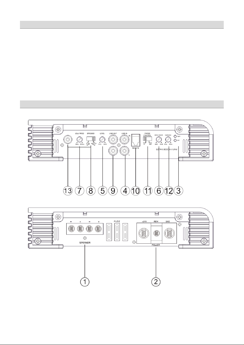
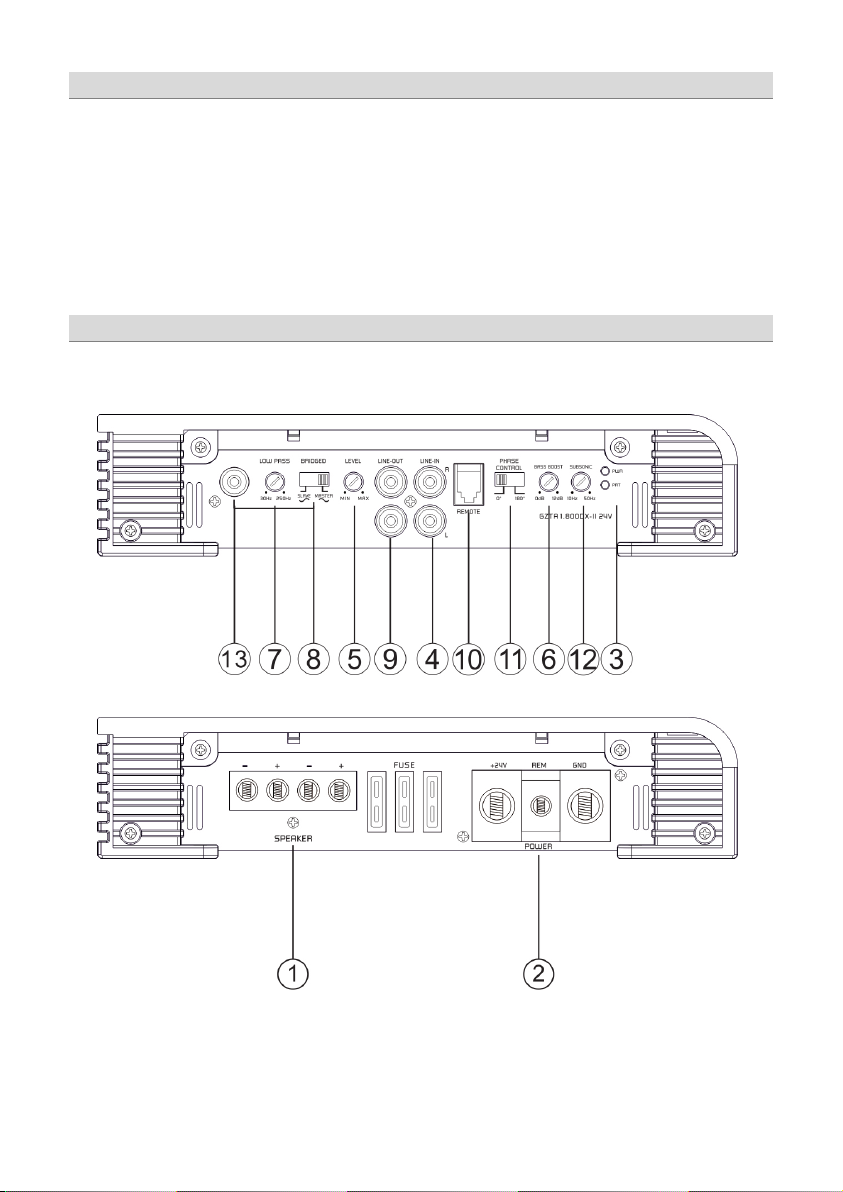
Einstellungen und Funktionen
1
Lautsprecheranschlüsse
Zum Anschluss der Lautsprecher
2
Stromanschluss
GND -> Masse Anschluss
3
Zustandsanzeige
GRÜN – OK
4
Cinch Eingänge
An diesen Anschlüssen schließen Sie die Cinchleitungen an.
5
Input Levelregler
Mit diesem Regler regulieren Sie die Eingangsempfindlichkeit.
6
Bass Boost Regler
Zum Einstellen des Ba ss Boost Levels im Bereich von 0 bis +12 dB.
7
Low Pass Regler
Es werden nur noch Frequenzen bis 30 Hz - 250 Hz wiedergeg eben
(abhängig von der Reglerstellung des LPF Filters). Justieren Sie die variable
LPF Frequenz mit dem Regler auf die gewünschte Frequenz.
8
Master / Slave Schalter
Zum Einstellen der jeweiligen Endstufe als Master oder Slave Endstufe im
Linkmode
9
Cinch Ausgänge
Für den Fullrange Betrieb einer zusätzlichen Endstufe.
10
Remote Control Eingang
Zum Anschluss des Bass Lautstärkereglers.
11
Phase Shift Schalter
12
Subsonic Regler
Zum Einstellen des Subsonic Filters im Bereich von 10 bis 50Hz.
13
Master/Slave Cinch-Anschluss
REM -> Remote Antennenanschluss
BATT -> +24 Volt
ROT – Fehler
Um Störung en zu vermeiden, verwenden Sie bitte hochwertige
Cinchkabel.
Dieser Schalter erlaubt Ihnen, den Subwooferkanal phasenrichtig an das
Frontsystem anzupassen.
Cinch Ein- / Ausg ang zum Betreiben zweier Endstufen des gleichen Typs im
Linkmodus.
Einschalten des Verstärkers
Der Verstärker schaltet sich automatisch einige Sekunden nach d em Einschalten des Radios ein.
Achtung: Ihr Verstärker schaltet sich z eitweise aus, wenn er überhitzt ist, schaltet sich jedoch nach der Abkühlung automatisch wieder ein
(ca. 80° C).
Einstellung des Audiopegels
1. LEVEL (MIN/MAX): mit Linksdrehung ganz auf MIN drehen.
2. Drehen Sie die Lautstärke am Radio auf ungefähr 1/3 der Höchstlautstärke.
3. Stellen Sie am LEVEL- Regler eine angenehme Lautstärke ein.
Page 5
- 5 -
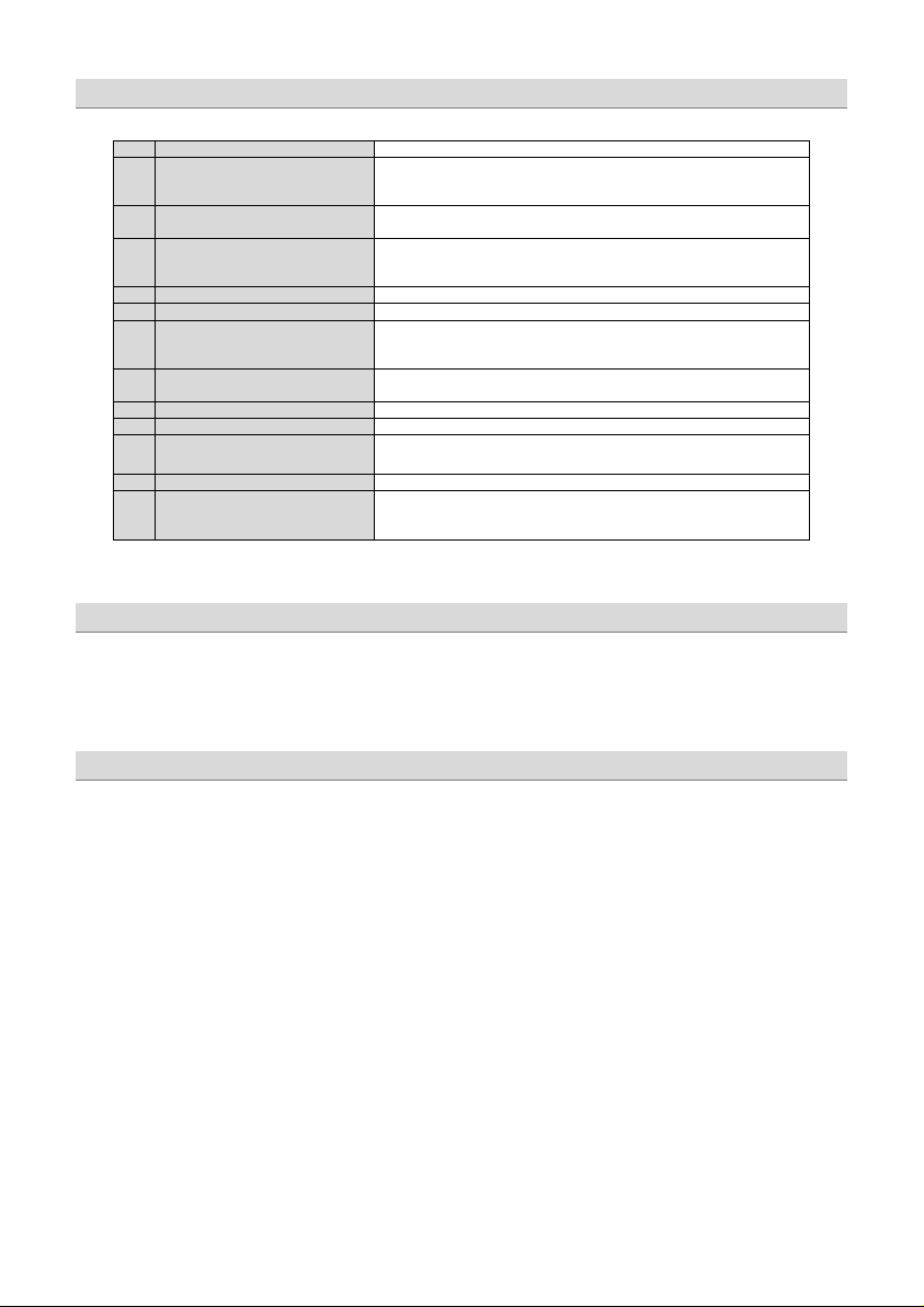
Stereo Anschluss
Page 6

- 6 -
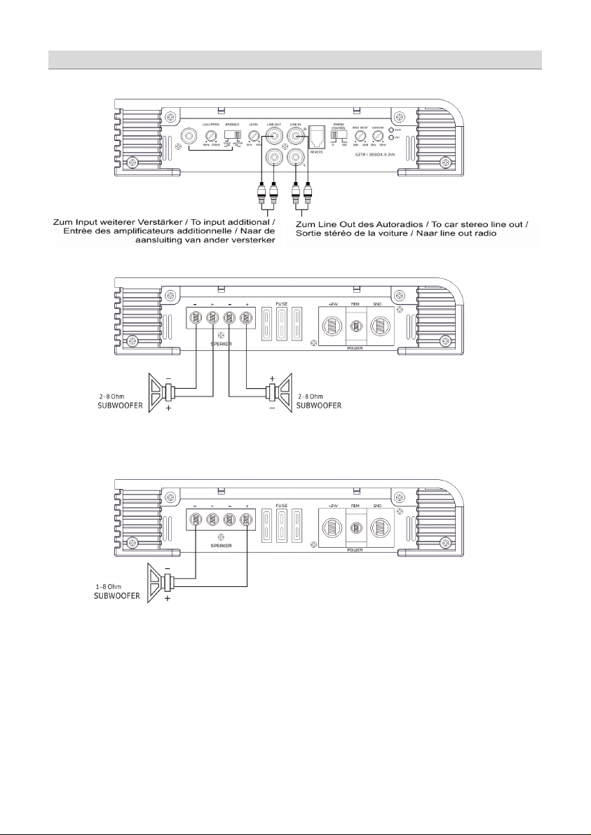
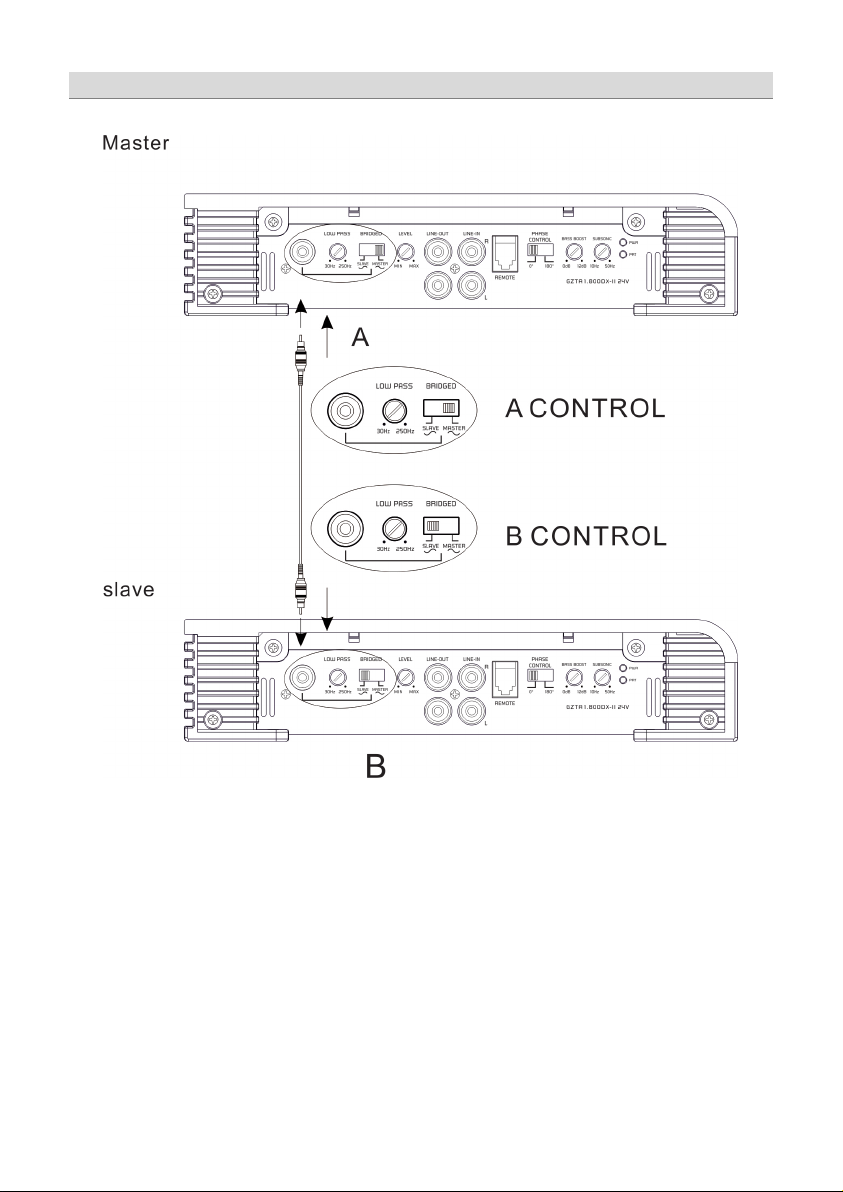
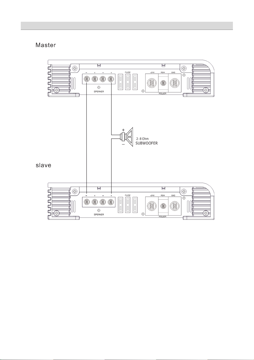
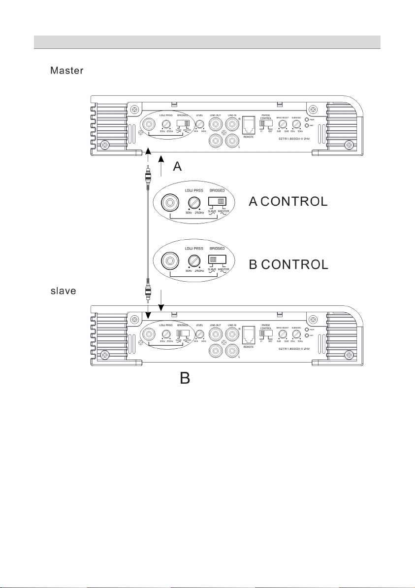
Master & Slave Anschluss
Page 7
- 7 -
Master & Slave Anschluss
Page 8
- 8 -
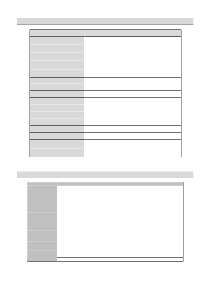
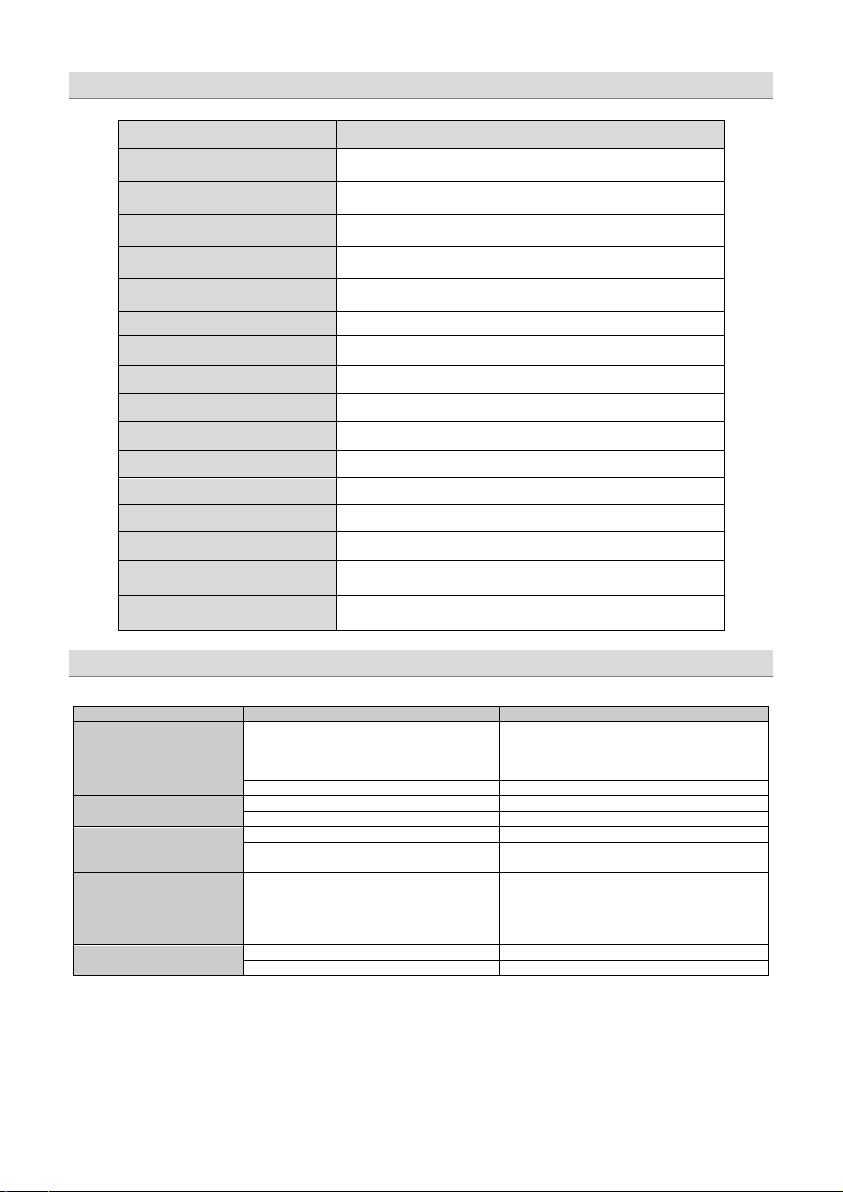
Model
GZTA 1.800DX-II24V
Typ
RMS Power @ 4 Ω
1 x 350 W
RMS Power @ 2 Ω
RMS Power @ 1 Ω
RMS Power @ 2 Ω Linkmode
1 x 1700 W
Dämpfungsfaktor
Tiefpass Weiche
Subsonic Filter
Bass boost
Frequenzgang
Eingangsempfindlichkeit
Betriebsspannung
Bass-Pegelfernbedienung
Sicherung
Abmessungen
B x H x L mm
Abmessungen
B x H x L inch
Problem
Kontrolle
Hilfe
Kurzschluss am Lautsprecher
Lautstärke verringern oder Gerät einige Zeit
abschalten
Kurzschluss am Lautsprecheranschluss
Lautsprecherkabel auf Kurzschluss prüfen
(Ermittel t bei 28 Vol t Betriebss pannung)
(Ermittel t bei 28 Vol t Betriebss pannung)
(Ermittel t bei 28 Vol t Betriebss pannung)
(Ermittel t bei 28 Vol t Betriebss pannung)
Kein Ton
Verstärker scha ltet
nicht ein
Verstärker scha ltet
bei Lautstärke ab
Ton fehlt an einem
Kanal
Protection LED
leuchtet
Technische Daten
1 Kanal Class D
(1% THD+N)
1 x 450 W (10% THD+N)
1 x 550 W (1% THD+N)
1 x 750 W (10% THD+N)
1 x 850 W (1% THD+N)
1 x 1000 W (10% THD+N)
1 x 2000 W (10% THD+N)
10 Hz – 250 Hz (± 1 dB)
20 – 32 Volt ( Remote on 10 – 32 Volt )
14.41“ x 2.01“ x 9.04“
(1% THD+N)
> 100
30 Hz – 250 Hz
10 Hz – 50 Hz
0 ~ +12 dB (45 Hz)
200 mV – 9 V (± 5%)
3 x 15A
366 x 51 x 230 mm
Fehlerdiagnose
Sicherung prüfen
Leuchtet die PWR LED?
Leuchtet die PROT LED?
Keine Stromzufuhr
Keine Spannung am Remote Remote am Radio prüfen
Lautsprecherimpedanz prüfen
Cinch / Lautsprecherkabel prüfen Kabel/Stecker beschädigt
Verstärker überhitzt
Remote Kabel prüfen
+24Volt prüfen
Masse prüfen
Gerät überhitzt
Gerät defe kt
Sicherung prüfen
+24Volt prüfen
Masse prüfen
Prüfen Sie, ob der Widerstand am LS Terminal
von 1 Ohm nicht unterschritten wird
Page 9

- 9 -
Erlenweg 25, 85658 Egmating, Germany
Tel. +49 (0)8095/873 830 Fax -8310
www.ground-zero-audio.com
Die Gewährleistung entspricht der gesetzlichen Regelung. Eine Rücksendung kann nur nach vorheriger Absprache und in der
Originalverpackung erfolgen. Bitte unbedingt einen maschinell erstellten Kaufbeleg und eine Fehlerbeschreib ung beilegen. Von der
Gewährleistung ausgeschlossen sind Defekte, die durch Überlastung, unsachgemäße Behandlung oder bei Teilnahme an Wettbewerben
entstanden sind. Wir behalten uns das Recht vor, zukünftig nötige Änderungen oder Verbesserungen an dem Produkt vorzunehmen ohne
Limited warranty - defective products must be returned in original packaging - please add a copy of the original purchasing invoice showing
the purchasing date and a detailed description of the failure. Failure caused by overload, misuse or by using the product for competition
purpose are not covered by the warranty. We reserve the right to make needed cha nge or improvement to the product without in forming
De Garantie bepalingen van alle door ground zero geleverde producten is volgens wettelijke
verpakking plaatsvinden.SVP een aankoopbon en een duidelijke storingsomschrijving bijvoegen.Van garantie uitgesloten zijn defecten door
overbelasting, onkundig gebruik, of door deelname aan wedstrijden (SPL) ontstaan zijn. Wij behouden ons het rech t om de nodige
emballage d'origine sur présentation du reçu ou de la facture indiquant la description du defaut.La présente Garantie n'est pas applicable
lorsque le produit a été endommagé en raison: Mauvaise alimentation, Trop de puissance (HP,Subwoofer) Accident, Installation ou
Utilisation non conforme aux normes Technique (Concours SPL etc). Nous nous réservons le droit d'entreprendre à l'avenir nécessa irement
bepalingen geregeld, Een retourzending kan alleen na duidelijke afspraak en in de originele
veranderingen of verbeteringen aan het product door te voeren zonder de klant hierover te informeren.
La garantie est conforme aux droits légaux. Un retour du produit défectueux doit être dans son
den Kunden darüber zu informieren.
customer about this in advance.
des modifications ou des
améliorations au produit sans informer le client.
Ground Zero GmbH
Page 10

TITANIUM-SERIES
AMPLIFIER
OWNER’S MANUAL
GZTA 1.800DX-II24V
Features
• For trucks and other vehicles with 24 Volt power supply
• 1 Ohm stable
• Linkable 2 Ohm
• Mosfet power supply
• Power and protection indicator
• Variable 12dB Bass boost (45Hz)
• Phaseshift 0 / 180° (Switch)
• Variable Subsonic
• Variable Lowpass
• Adjustable input sensitivity
• Soft delayed remote turn on
• Stereo RCA output
• Bass remote control
• Thermal / Short / Overload protection
Page 11

- 2 -
Tools and materials you need
WARNING !
• Screwdriver
• Electric drill, 3 mm / 0.12” carbide drill bit
• Mounting screws
• Power wire min. 20 mm² / 4 AWG
• Ground wire min. 20 mm² / 4 AWG
• Speaker wire min. 2 x 2,5 mm²
Please note!
• As a precaution it is advisable to disconnect the vehicle’s battery before making connection to the +24 Volts supply wiring
(see owner’s manual of your car for further information).
• Please use great caution drilling your trunk. Your gas tank and brake lines can be damaged by puncturing with your drill bit –
this could cause damage or failure of your cars operating systems.
• Never pass wires over sharp angles.
High powered audio systems in a vehicle are capable of generating "Live Concert" levels of sound pressure. Continued exposure to
excessively high volume sound levels may cause hearing loss or damage. Also, operation of a motor vehicle while listening to audio
equipment at high volume levels may impair your ability to hear external sounds such as; horns, warning signals, or emergency vehicles,
thus constituting to a potential traffic hazard. In the interest of safety, Consumer Electronics recommends listening at lower volume levels
while driving.
Before beginning the installation, consider the following:
a) If you plan to expand your system by adding other components sometime in the future, ensure adequate space is left, and
cooling requirements are met.
b) If your radio is equipped with preamplifier outputs (RCA), it is advisable to use them.
Mounting your amplifier
Planning your system
a) Select a suitable location that is convenient for mounting, is accessible for wiring and has ample room for air circulation and
cooling.
b) Use the amplifier a s a template to mark the mounting holes, remove the amplifier and drill 4 holes. Then mount the amplifier
with the mounting screws.
Page 12
- 3 -
Chose a mounting position where all electric wires are protected from being damaged by sharp edges, heat or other conditions. +24 Volt
DC electrical connections must be fused on the battery side. Ma ke sure your ra dio a nd all other devices will be turned off while connection
your system.
If you need to replace the power fuse, replace it only with a fus e identical to that s upplied with the system. Using a fuse of different type or
rating may result in damage to this system which isn’t covered by the warranty.
Please do only use in 24 Volt systems! 12 Volt use may result in a defect of your system and / or th e amplifier!
Controls and functions
Warning
Page 13
- 4 -
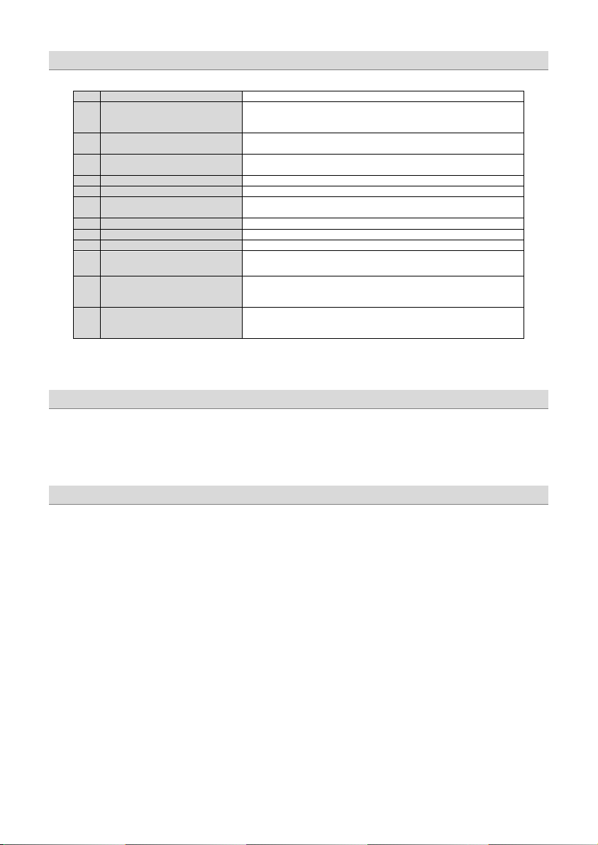
Control and functions
1
Speaker terminals
For connection of the subwoofer
2
Power terminals
GND -> Ground connection
3
Satus indication
GREEN – OK
4
Cinch inputs
Terminal for connection of the RCA wires.
To avoid failure, please use high quality RCA wires.
5
Input level controller
With this controller you can adjust the input sensitivity.
6
Bass boost controller
For adjusting of the bass boost level in the range from 0 to +12 dB.
7
Low pass controller
Adjust the variable lowpass frequency to the desired frequency between 30
8
Master / Slave Switch
For choosing the operation mode of each amplifier in link mode.
9
Cinch Outputs
For connection of additional amplifiers in fullrange operation.
10
Remote control input
For connection of the bass remote control.
11
Phase shift controller
12
Subsonic controller
This controller allows you to filter low frequencies in a range between 10
13
Master/Slave
Cinch-In-/Output
REM -> Remote antenna terminal
BATT -> +24 Volt
RED – Error
and 250 Hz using the controller.
This controller allows you to fit the subwoofer channel in-phase to the front
system.
and 50 Hz. This fun ction reduces the mechanical Xmax and raises the
capacity of the connected subwoofer.
Cinch In- / Output for operation of two same amplifiers in linkmode.
Turning on the amplifier
The amplifier automatically turns on a few seconds after you turn on your radio.
Note: Your amplifier temporarily shuts down if it gets too hot, then restarts automatically once it cools
(At about 80° / 176° F).
Adjusting the audio level
1. LEVEL (Min/Max): Turn fully counter- clockwise to MIN position
2. Turn the auto sound system's volume control to about two-third of its full range.
3. Adjust LEVEL to a comfortable listening level.
Page 14

- 5 -
Stereo wiring
Page 15
- 6 -
Master & slave wiring
Page 16
- 7 -
Master & slave wiring
Page 17
- 8 -
Specifications
Model
GZTA 1.800DX-II24V
Type
RMS Power @ 4 Ω
(28 Volt)
1 x 350 W
RMS Power @ 2 Ω
(28 Volt)
RMS Power @ 1 Ω
(28 Volt)
RMS Power @ 2 Ω Linkmode
(28 Volt)
1 x 1700 W
Damping factor
Lowpass
Subsonic filter
Bass boost
Frequency response
Input sensitivity
Operating voltage
Bass remote control
Fuse
Dimensions
W x H x L mm
Dimensions
W x H x L inch
Symptoms
Check Points
Cure
Check fuses in amplifier.
Check ground connection
Is the diagnostic LED illuminated?
Check for speaker short or amplifier overheating
No power to the amplifier
Check power wire or connections
No power to remote wire with receiver on
Check connections to radio
Check spea ker leads
Inspect for short circuit or an open connection
Reverse left and right RCA inputs to determine if it
is occurring before the amp
Be sure proper speaker load impedance
and AC impedance may not be the same.)
Temperature shut down
Turn radio volume down
Speaker wires short
Separate speaker wires and insulate
1 Channel Class D
(1% THD+N)
1 x 450 W (10% THD+N)
1 x 550 W (1% THD+N)
1 x 750 W (10% THD+N)
1 x 850 W (1% THD+N)
1 x 1000 W (10% THD+N)
1 x 2000 W (10% THD+N)
10 Hz – 250 Hz (± 1 dB)
20 – 32 Volt ( Remote on 10 – 32 Volt )
(1% THD+N)
> 100
30 Hz – 250 Hz
10 Hz – 50 Hz
0 ~ +12 dB (45 Hz)
200 mV – 9 V (± 5%)
3 x 15A
366 x 51 x 230 mm
14.41“ x 2.01“ x 9.04“
Trouble shooting guide
No sound
Amp not switching on
No sound in one channel
Amp turning off at medium /
high volume
Protection LED is on
Is the POWER LED illuminated?
Check audio leads
Check speaker load impedance
Be sure remote lead is connected.
Check +24 Volt connection
recommendations are observed
(If you use an ohm meter to check speaker
resistance, please remember that DC res istance
Page 18

- 9 -
Erlenweg 25, 85658 Egmating, Germany
Tel. +49 (0)8095/873 830 Fax -8310
www.ground-zero-audio.com
Die Gewährleistung entspricht der gesetzlichen Regelung. Eine Rücksendung kann nur nach vorheriger Absprache und in der
Originalverpackung erfolgen. Bitte unbedingt einen maschinell erstellten Kaufbeleg und eine Fehlerbeschreibung beilegen. Von der
Gewährleistung ausgeschlossen sind Defekte, die durch Überlastung, unsachgemäße Behandlung oder bei Teilnahme an Wettbewerben
entstanden sind. Wir behalten uns das Recht vor, zukünftig nötige Änderungen oder Verbesserungen an dem Produkt vorzunehmen ohne
Limited warranty - defective products must be returned in original packaging - please add a copy of the original purchasing invoice showing
the purchasing date and a detailed description of the failure. Failure caused by overload, misuse or by using the product for competition
purpose are not covered by the warranty. We reserve the right to make needed cha nge or improvement to the product without in forming
De Garantie bepalingen van alle door ground zero geleverde producten is volgens wettelijke
verpakking plaatsvinden.SVP een aankoopbon en een duidelijke storingsomschrijving bijvoegen.Van garantie uitgesloten zijn defecten door
overbelasting, onkundig gebruik, of door deelname aan wedstrijden (SPL) ontstaan zijn. Wij behouden ons het rech t om de nodige
emballage d'origine sur présentation du reçu ou de la facture indiquant la description du defaut.La présente Garantie n'est pas applicable
lorsque le produit a été endommagé en raison: Mauvaise alimentation, Trop de puissance (HP,Subwoofer) Accident, Installation ou
Utilisation non conforme aux normes Technique (Concours SPL etc). Nous nous réservons le droit d'entreprendre à l'avenir nécessairement
bepalingen geregeld, Een retourzending kan alleen na duidelijke afspraak en in de originele
veranderingen of verbeteringen aan het product door te voeren zonder de klant hierover te informeren.
La garantie est conforme aux droits légaux. Un retour du produit défectueux doit être dans son
den Kunden darüber zu informieren.
customer about this in advance.
des modifications ou des
améliorations au produit sans informer le client.
Ground Zero GmbH
Page 19

TITANIUM-SERIES
AMPLIFICADOR
MANUAL DEL USUARIO
GZTA 1.800DX-II24V
• Para camiones y otros vehículos con alimentación de 24 voltios
• 1 Ohm estable
• Linkeable 2 Ohm
• Mosfet Fuente de Poder
• Power & Protection indicator
• Variable 12dB bass boost (45Hz)
• Variable low pass filter
• Variable subsonic filter
• Phaseshift 0 / 180° (Switch)
• Sensibilidad de entrada Ajustable
• Soft delayed remote turn- on
• Stereo RCA output
• Control remoto
• Thermal / Short / Overload protección
Caracteristicas
Page 20

- 2 -
ATENCION !
• Desarmador
• Taladro Eléctrico, 3 mm / 0.12” mecha de carbono
• Tornillos de Montura
• Cable de Poder min. 20 mm²
• Cable de Tierra min. 20 mm²
• Cable para Altavoz min. 2 x 2,5 mm²
Por favor tome atencion!
Herramientas y materiales necesarios
• Como medida de precaución, es aconsejable desconectar la batería del vehículo antes de realizar la conexión del cableado de
alimentación 24 Voltios (véase el manual de usuario de su vehículo para más información).
• Por favor, tenga especial cuidado al taladrar el metal del vehiculo. Su tanque de combustible o lineas de freno puede ser dañada por
punción con la broca - esto podría causar daños o averías de sus vehículos y sus sistemas operativos.
• Nunca pase cables por encima de los ángulos agudos o afilados.
Los sistemas de alta potencia de audio en un vehículo son capaces de generar los niveles de presión sonora equivalentes a "Live Concert".
La exposición continua a niveles excesivamente altos de volumen puede causar pérdida de audición o daños. Además, la operación de un
vehículo de motor mientras se escucha a los equipos de audio a un volumen muy alto puede perjudicar su capacidad para oír
sonidos externos, tales como: bocinas, señales de advertencia, o vehículos de emergencia, lo que constituye un peligro para el tráfico
potencial. En aras de su seguridad, Electrónica de Consumo recomienda escuchar al volumen más bajo posible durante la conducción.
Planificacion de su sistema
Antes de comenzar la instalación, considere lo siguiente:
a. Si tiene previsto ampliar el sistema mediante la adición de otros componentes en el futuro, asegurese de dejar un espacio adecuado, y
que se cumplen con los requisitos de refrigeracion.
b. Si la radio o la fuente está equipada con salidas pre-amplificador, es posible utilizarlos para correr el amplificador y conectar
(amplificador) a los 2 altavoces traseros.
Montaje de su amplificador
a. Seleccione un lugar adecuado que sea conveniente para el montaje, que sea accesible para el cableado
b. Utilice el amplificador como plantilla para marcar los agujeros de montaje.
y que tenga un amplio espacio para la circulación del aire y para la refrigeración.
Page 21

- 3 -
Elija una posición de montaje en el que todos los cables están protegidos de ser dañados por bordes cortantes, calor u otras condiciones.
La conexión eléctrica + 24 voltios DC deben ser conectada coun un fusible y directamente en el lado (+) de la batería. Asegúrese de
que su radio y todos los otros dispositivos esten desconectados mientras realice la instalacion de su sistema.
Si necesita reemplazar el fusible, cámbielo por un fusible con idéntica capacidad al que se suministra con el sistema. El uso de un fusible
del tipo o capacidad distinto puede resultar en daño a este sistema, que no estará cubierto por la garantía.
Por favor usar solo en sistemas de 24 Voltios, 12 voltios podría dañar su vehículo/ o amplificador.
Controles y funciones
Atencion
Page 22

- 4 -
Controles y funciones
1
Terminal de Alta voces
Para conectar los altavoces
2
Terminales de Poder
GND -> Terminal de Tierra
3
Indicador de Estatus
GREEN – OK
4
Entradas RCA
Terminales para la conexión de cables RCA.
Para evitar Fallos por favor Utilice cables RCA de alta calidad.
5
Control de nivel de entrada
Con este control puede ajustar el nivel de entrada .
6
Control Bass boost
Para ajustar el nivel bass boost en el rango desde 0 to +12 dB.
7
Control Low pass
Para ajustar el lowpass frequency al nivel des eado entre las frecuencia s 30
8
Master / Slave Switch
Para ajustar el modo de operación de cada amplificador entre maestro y
9
Salidas RCA
Para conectar amplificadores adicionales en modo fullrange.
10
Entrada conexion Control remoto
Para conectar el bass control .
11
Controlador Phase shift
12
Controlador Subsonic
Este control permite ajustar y filtrar low frequencies en un rango entre 10
13
Master/Slave
Cinch-In-/Output
REM -> Terminal de Remoto Antena
BATT -> +24 Volt
RED – Error
and 250 Hz usando el control.
esclavo.
Este control permite ajustar el canal del subwoofer channel in-phase con
el sistema frontal.
and 50 Hz. Esta función reduce el movimiento mecánico del Xmax y
aumenta la capacidad de uso del subwoofer.
Conexión RCA In- / Output para operación de dos amplificadores del
mismo modelo en linkmode.
Encendido del amplificador
El amplificador se enciende automáticamente unos segundos después de encender su radio.
Nota: El amplificador se apaga temporalmente si se pone demasiado caliente, entonces reinicia automáticamente una vez que se enfría
(En el 80 ° / 176 ° F).
Ajuste del nivel de audio
1. NIVEL (Min / Max): Dé vuelta completamente a la izquierda a la posición MIN
2. Gire el control del sistema de sonido para automóviles de volumen hasta, aproximadamente dos tercios de toda su gama.
3. Ajuste el nivel para obtener un nivel cómodo.
Page 23

- 5 -
Cableado estereo
Page 24

- 6 -
Cableado master & slave
Page 25

- 7 -
Cableado master & slave
Page 26

- 8 -
Modelo
GZTA 1.800DX-II24V
Tipo
RMS Power @ 4 Ω
(28 Volt)
1 x 350 W
RMS Power @ 2 Ω
(28 Volt)
RMS Power @ 1 Ω
(28 Volt)
RMS Power @ 2 Ω Linkmode
(28 Volt)
1 x 1700 W
Damping factor
Lowpass
Subsonic filter
Bass boost
Repuesta de frecuencia
Input sensitivity
Voltaje de funcionamiento
Control remoto Bass
Fusible
Dimensiones
W x H x L mm
Dimensiones
W x H x L inch
1 Channel Class D
(1% THD+N)
1 x 450 W (10% THD+N)
1 x 550 W (1% THD+N)
1 x 750 W (10% THD+N)
1 x 850 W (1% THD+N)
1 x 1000 W (10% THD+N)
1 x 2000 W (10% THD+N)
10 Hz – 250 Hz (± 1 dB)
20 – 32 Volt ( Remote on 10 – 32 Volt )
(1% THD+N)
> 100
30 Hz – 250 Hz
10 Hz – 50 Hz
0 ~ +12 dB (45 Hz)
200 mV – 9 V (± 5%)
3 x 15A
366 x 51 x 230 mm
14.41“ x 2.01“ x 9.04“
Specifications
Page 27

- 9 -
Síntoma s
Puntos de Chequeo
Solución
No hay sonido
Revise los fusibles en el
Revise si el altavoz es ta en corto o si
El amplificador no enciende
El amplificador no tiene corriente
Revise la conexiones de los altavoz
No tiene corriente el cable remoto
No hay sonido en uno de los
canales
Inspeccione si hay un cortocircuito o
Reverso entradas izquierda y
El amplificado se apaga a medio
volumen / alto volumen
Asegúrese deobservar las
El Protección LED esta encendido
Apagado por temperatura
Baje el nivel de la unidad de Radio
Separar y aislar los cables de
Guia de problemas
amplificador.
Revise si el control remoto esté
conectado.
Esta el POWER LED iluminado?
Esta el diagnostic LED iluminado?
Compruebe conductores de la
señal.
Compruebe de nuevo el control.
Compruebe sintonizador / nivel de
volumen de la cubierta.
el amplificador esta sobrecalentado
con el recibidor encendido
Revise la conexión del altavoz
Revise la conexión de Audio
Revise la carga de Impedancia de
los Altavoces
Corto en Cableado de Altavoces
Revise la conexión del Radio
una conexión abierta
derecha RCA para determinar si se
está produciendo para que el
amplificador
recomendaciones impedancia del
altavoz.
(Si utiliza un medidor de ohmios
para comprobar la resistencia del
altavoz, por favor recuerde que la
resistencia DC y la impedancia de
AC puede no ser la misma.)
altavoces
Page 28

- 10 -
Erlenweg 25, 85658 Egmating, Germany
Tel. +49 (0)8095/873 830 Fax -8310
www.ground-zero-audio.com
Die Gewährleistung entspricht der gesetzlichen Regelung. Eine Rücksendung kann nur nach vorheriger Absprache und in der
Originalverpackung erfolgen. Bitte unbedingt einen maschinell erstellten Kaufbeleg und eine Fehlerbeschreibung beilegen. Von der
Gewährleistung ausgeschlossen sind Defekte, die durch Überlastung, unsachgemäße Behandlung oder bei Teilnahme an Wettbewerben
entstanden sind. Wir behalten uns das Recht vor, zukün ftig nötige Änderungen oder Verbesserungen an dem Produkt vorzunehmen ohne
Limited warranty - defective products must be returned in original packaging - please add a copy of the original purchasing invoice showing
the purchasing date and a detailed description of the failure. Failure caused by overload, misuse or by using the product for competition
purpose are not covered by the warranty. We reserve the right to make needed change or improvement to the product without informing
De Garantie bepalingen van alle door ground zero geleverde producten is volgens wettelijke
verpakking plaatsvinden.SVP een aankoopbon en een duidelijke storingsomschrijving bijvoegen.Van garantie uitgesloten zijn defecten door
overbelasting, onkundig gebruik, of door deelname aan wedstrijden (SPL) ontstaan zijn. Wij behouden ons het recht om de nodige
emballage d'origine sur présentation du reçu ou de la facture indiquant la description du defaut.La présente Garantie n'est pas applicable
lorsque le produit a été endommagé en raison: Mauvaise alimentation, Trop de puissance (HP,Subwoofer) Accident, Installation ou
Utilisation non conforme aux normes Technique (Concours SPL etc). Nous nous réservons le droit d'entreprendre à l'avenir nécessairement
bepalingen geregeld, Een retourzending kan alleen na duidelijke afspraak en in de originele
veranderingen of verbeteringen aan het product door te voeren zonder de klant hierover te informeren.
La garantie est conforme aux droits légaux. Un retour du produit défectueux doit être dans son
den Kunden darüber zu informieren.
customer about this in advance.
des modifications ou des
améliorations au produit sans informer le client.
Ground Zero GmbH
Page 29

TITANIUM-SERIES
VAHVISTIMEN
KÄYTTÖOHJE
GZTA 1.800DX-II24V
Ominaisuudet
• Kuorma-autoihin ja muihin ajoneuvoihin joissa on 24 voltin virtajärjestelmä
• 1 Ohm vakaa
• Linkattuna 2 Ohm
• Mosfet virtalähde
• Virta ja suojaus merkkivalot
• Säädettävä 12dB Basson korostus (45Hz)
• Vaiheenkääntö 0 / 180° (Kytkin)
• Säädettävä Subsonic- suodin
• Säädettävä alipäästösuodin
• Säädettävä sisääntulotasonsäätö
• Käynnistyksen viivepiiri
• Stereo RCA ulostulo
• Bassonkaukosäädin
• Lämpö / oikosulku / ylikuormitus suoja
Page 30

- 2 -
Työkalut ja tarvikkeet mitä tarvitset vahvistimen asennukseen
VAROITUS!
• Ruuvimeisseli
• Porakone, 3 mm / 0. 12” poranterä
• Kiinnitysruuvit
• Virtajohto min. 20 mm² / 4 AWG
• Maadoitusjohto min. 20 mm² / 4 AWG
• Kaiutinjohto min. 2 x 2,5 mm² / 15 AWG
Huomioitavaa!
• Varmuuden vuoksi on hyvä irroittaa auton akun maakaapeli ennen vahvistimen virtaliittimien kytkentöjä. (Katso auton
käyttöoppaasta tarkemmat tiedot).
• Käytä varoivaisuutta poratessasi mahdollisia reikiä auton tavaratilassa. Polttoaine- ja jarruputket saattavat vaurioitua reikää
poratessasi – tämä voi auheuttaa vakavia turvallisuusriskejä.
• Älä koskaan vedä johtoja terävien kulmien ja reunojen yli.
Tehokkaa t autohifijärjestelmät ovat kykeneviä tuottamaan Live-konserttitasoisia äänenpaineita. Jatkuva altistuminen korkeille äänenpaineille
saattaa vaurioittaa kuuloasi pysyvästi. Myöskin korkea kuunteluvoimakkuus saattaa estää sinua kuulemasta ajoneuvon ulkopuolisia ääniä
kuten; torvien ja hälytysajoneuvojen sireeniä.
Järjestelmän suunnittelu
Ennen asennuksen aloittamista, harkitse seuraavaa:
Jos harkitset järjestelmän laajentamista tulevaisuudessa, varmista että tilaa on riittävästi, ja vaatimukset jäähdytykselle täyttyvät myös
tulevaisuudessa laitteiden määrän lisääntyessä.
Vahvistimen asentamisesta
a. Valitse sopiva asennuspaikka, johon saat johdotuksen ja jossa on riittävästi tilaa ilmankierrolle sekä jäähdytykselle.
b. Käytä vahvistinta mallina kun merkkaat kiinnitysreiät.
Page 31

- 3 -
Valitse asennuspaikka siten että kaikki johdot ovat suojassa teräviltä kulmilta, lämmöltä tai muilta vauriollisilta olosuhteilta. Virtakaapeli
tulee suojata päävirtasulakkeella mahdollisimman läheltä akkua. Varmista että ohjelmalähteesi ja kaikki muut järjestelmän laitteet ovat pois
päältä kytkentöjä tehdessäsi.
Jos sinun täytyy vaihtaa sulake, korvaa se ainoastaan alkuperäisen kokoisella sulakkeella. Eri kokoisen tai tyyppisen sulakkeen käyttö voi
vahingoittaa laitteistoasi, mikä ei kuulu takuun piiriin.
Käytä vain 24 voltin virtajärjestelmissä. 12 voltin käyttö voi vahingoittaa järjestelmääsi ja/tai vahvistinta!
Kytkimet ja toiminnot
Varoitus
Page 32

- 4 -
Kytkimet ja toiminnot
1
Kaiutinliittimet
Subwooferin kaiutinjohdot
2
Virtaliittimet
GND -> Maajohto
3
Tilan merkkivalo
VIHREÄ – OK
4
RCA sisääntulot
Signaalikaapelit.
Häiriöiden välttämiseksi, käytä hyvälaatuisia RCA-johtoja.
5
Sisääntulotason säätö
Tällä säätimellä säädät sisääntulotason sopivaksi.
6
Bassonkorostuksen säätö
Bassontason säätöön portaattomalla korostuksella 0 +12 dB.
7
Alipäästösuodin
Säädä haluttu jakotaajuus väliltä 30-250 Hz
8
Master / Slave kytkin
Linkitetyn vahvistimen valintakytkin.
9
RCA ulostulot
Kytkentä lisävahvistimelle.
10
Basson kaukosäädin
Liitäntä basson kaukosäädölle.
11
Vaiheenkäännön säädin
12
Subsonic säädin
Säädä haluttu arvo subsonic suotimelle alueella 10-50 Hz.
13
Master/Slave
RCA-sisään-/ulostulo
REM -> Herätevirta
BATT -> +24 Volttia
PUNAINEN – VIRHE
Tämä kytkin mahdollistaa subwoofer kanavan vaiheen sovittamisen
yhtenäiseksi muun kaiutinjärjestelmän kanssa.
RCA sisään- / ulostulot linkkaukseen.
Vahvistimen käynnistys
Kun laitat ohjelmalähteen päälle vahvistin käynnistyy automaattisesti.
Huomaa: Vahvistin kytkeytyy tilapäisesti pois päältä, mikäli sen lämpötila nousee liian kuumaksi. Lämpötilan laskettua normaaliksi vahvistin
käynnistyy jälleen automaattisesti. (noin 80°).
Sisääntulon säätö
1. LEVEL (Min/Max): Käännä säädin täysin MIN asentoon
2. Käännä äänenvoimakkuussäädin asentoon kaksi kolmasosaa maksimivoimakkuudesta.
Säädä LEVEL-säätimestä tasoa lisää siihen saakka kunnes ääni kuulostaa vielä puhtaalle.
Page 33

- 5 -
Stereo kytkentä
Page 34

- 6 -
Master & slave kytkentä
Page 35

- 7 -
Master & slave kytkentä
Page 36

- 8 -
Tekniset tiedot
Malli
GZTA 1.800DX-II24V
Tyyppi
RMS teho @ 4 Ω
(28 Volt)
1 x 350 W
RMS teho @ 2 Ω
(28 Volt)
RMS teho @ 1 Ω
(28 Volt)
RMS teho @ 2Ω linkattuna
(28 Volt)
1 x 1700 W
Vaimennuskerroin
Alipäästösuodin
Subsonic suodin
Bassonkorostus
Taajuusvaste
Sisääntuloherkkyys
Käyttöjännite
Bassonkaukosäädin
Sulake
Mitat
W x H x L mm
Mitat
W x H x L tuumaa
1-Kanava D-luokka
(1% THD+N)
1 x 450 W (10% THD+N)
1 x 550 W (1% THD+N)
1 x 750 W (10% THD+N)
1 x 850 W (1% THD+N)
1 x 1000 W (10% THD+N)
1 x 2000 W (10% THD+N)
10 Hz – 250 Hz (± 1 dB)
20 – 32 Volt ( Remote on 10 – 32 Volt )
(1% THD+N)
> 100
30 Hz – 250 Hz
10 Hz – 50 Hz
0 ~ +12 dB (45 Hz)
200 mV – 9 V (± 5%)
3 x 15A
366 x 51 x 230 mm
14.41“ x 2.01“ x 9.04“
Page 37

- 9 -
Ongelman kuvaus
Tarkasta
Toimenpide
Ei ääntä
Tarkasta vahvistimen sulakkeet.
Tarkasta etteivät kaiutinjohdot ole
Vahvistin ei käynnisty
Tuleeko vahvistimelle virta?
Tarkasta virtajohdotus.
Tuleeko vahvistimelle herätevirta?
Tarkasta ohjelmalähteen kytkennät.
Ei ääntä yksittäisestä kaiutinlähdöstä
Tarkasta että kaiutinjohdot ovat
Käännä vasen ja oikea RCA johto
Vahvistin kytkeytyy pois päältä
keskimääräisellä / kovalla
voimakkuudella
Protection LED p alaa
Onko vahvistin ylikuumentunut?
Vähennä äänenvoimakkuutta
Tarkasta kaiutinjohtojen kytkennät ja
Ongelman esiintyessä
Tarkasta onko herätevirtajohto
kytketty.
Palaako POWER LED valo?
Tarkista signaalikaapelit.
Tarkasta kytkimen asennot.
Tarkasta ohjelmalähteen
äänenvoimakkuussäätimen asento.
Palaako diaknostiikka LED valo?
Onko vikaa kaiutinjohdotuksessa?
Onko vikaa signaalikaapeleissa?
Onko väärä kaiutinkuorman
impedanssi?
Onko kaiutinjohdot oikosulussa?
oikosulussa tai vahvistin
ylikuumentunut.
kytketty ja että ne eivät ole
oikosulussa.
selvittääksesi onko vika ennen
vahvistinta.
Varmistu että kaiutinkuorman
impedanssi on suositellun kaltainen.
eristeet
Page 38

- 10 -
Erlenweg 25, 85658 Egmating, Germany
Tel. +49 (0)8095/873 830 Fax -8310
www.ground-zero-audio.com
Die Gewährleistung entspricht der gesetzlichen Regelung. Eine Rücksendung kann nur nach vorheriger Absprache und in der
Originalverpackung erfolgen. Bitte unbedingt einen maschinell erstellten Kaufbeleg und eine Fehlerbeschreibung beilegen. Von der
Gewährleistung ausgeschlossen sind Defekte, die durch Überlastung, unsachgemäße Behandlung oder bei Teilnahme an Wettbewerben
entstanden sind. Wir behalten uns das Recht vor, zukünftig nötige Änderungen oder Verbesserungen an dem Produkt vorzunehmen ohne
Limited warranty - defective products must be returned in original packaging - please add a copy of the original purchasing invoice showing
the purchasing date and a detailed description of the failure. Failure caused by overload, misuse or by using the product for competition
purpose are not covered by the warranty. We reserve the right to make needed change or improvement to the product without informing
De Garantie bepalingen van alle door ground zero geleverde producten is volgens wettelijke
verpakking plaatsvinden.SVP een aankoopbon en een duidelijke storingsomschrijving bijvoegen.Van garantie uitgesloten zijn defecten door
overbelasting, onkundig gebruik, of door deelname aan wedstrijden (SPL) ontstaan zijn. Wij behouden ons het rech t om de nodige
emballage d'origine sur présentation du reçu ou de la facture indiquant la description du defaut.La présente Garantie n'est pas applicable
lorsque le produit a été endommagé en raison: Mauvaise alimentation, Trop de puissance (HP,Subwoofer) Accident, Installation ou
Utilisation non conforme aux normes Technique (Concours SPL etc). Nous nous réservons le d roit d'entreprendre à l'a venir nécessairement
bepalingen geregeld, Een retourzending kan alleen na duidelijke afspraak en in de originele
veranderingen of verbeteringen aan het product door te voeren zonder de klant hierover te informeren.
La garantie est conforme aux droits légaux. Un retour du produit défectueux doit être dans son
den Kunden darüber zu informieren.
customer about this in advance.
des modifications ou des
améliorations au produit sans informer le client.
Ground Zero GmbH
Page 39

TITANIUM-SERIES
AMPLIFICATEUR
MODE D’EMPLOI
GZTA 1.800DX-II24V
• Pour les camions et autres véhicules avec alimentations 24 Volts
• 1 Ohm stable
• Linkmode 2 Ohm
• Alimentation mosfet
• Alimentation / protection par LED
• 12dB Bass boost variable (45Hz)
• Phaseshift 0 / 180° (commutateur)
• Subsonic variable
• Filtre pass bas variable
• Sensibilité d’entrer variable
• Softstart, mise en fonction et hors fonction avec régulateur
• Sortie Stereo RCA
• Télécommande bass déporter
• Protection de température / court-circuit / surcharge
Signes caracteristiques
Page 40

- 2 -
Mise en garde !
Materiel et outillage necessaires a l’ installation
• Tournevis à croix
• Perceuse, mèche à métaux 3 mm
• Vis de fixation
• Câble d’alimentation min. 20 mm²
• Câble de masse min 20 mm²
• Câble haut- parleurs min. 2 x 2,5 mm²
• Débrancher la batterie du véhicule avant l’installation (Ces instructions font référence dans l'automobile!)
• Ne pas percer dans le réservoir, la canalisation freins ou autres pièces importantes du véhicule.
• Ne jamais passer les câbles sur un bord tranchant.
Le système audio de haute performance peu t reproduire ,dans les véhicules, une intens ité sonore semblable a un concert « LIVE ». Une
durée extrême de musique peut provoquer la perte de l’audition ou une diminution de celle ci. L’écoute de musique .à haut volume, en
roulant, peut provoquer une diminution de l’attention. Dans votre intérêt et votre sécurité, nous vous conseillons d’écouter la musique avec
un volume réduit en conduisant.
Planification
Attention s.v.p. !
Avant l’installation ces quelques points sont à prendre en considération
a) Attention au choix de l’emplacement du montage, une circulation d’air est nécessa ire pour un bon fonctionnement des
appareils.
b) Il est conseillé d’utiliser les sorties Pré- Ampli (RCA) de votre autoradio, si celle ci est munie.
Installation de l’amplificateur
a) Choisissez l’emplacement idéal pour que le câblage soit posé sans difficulté avec un espace suffisamment pour une
circulation d’air et un refroidissement constant.
b) Utiliser l’amplificateur comme modèle pour marquer l’emplacement du montage. Retirer l’amplificateur et perc er 4 trous.
Fixer l’amplificateur à l’aide des vis prévues à cet effet.
Page 41

- 3 -
Montez ce système d e façon à ce que les raccordements électroniques soient protégées d’évent uelles détériorations.
Les câbles électriques +24V DC coté batterie doivent êtr e protégés et prenez gard e à ce que la Radio et/ou autres appareils soient éteints
lors du branchement.
S’il est nécessaire de renouveler le fus ible d’un ap pareil utilisez seulement ceux de même unité de tension. N’utilisez pas de fusible avec
unité de tension différente à celle utilisée, cela pourrait provoquer des dommages que la garantie ne pourra couvrir.
S'il vous plaît ne l'utiliser que dans les systèmes 24 Volts! L’utilisation en 12 Volts p eut entraîner un défaut de votre système et / ou de
l'amplificateur!
Connexion et reglages
Mise en garde
Page 42

- 4 -
Connexion et reglages
1
Raccordement haut-parleur
Entrée des Branchement Haut-Pa rleur
2
Alimentation
GND -> Entrée Mass e
3
Indicateur d'état
VERT – OK
4
Entrée RCA
A ces raccords, vous connectez le RCA. Pour éviter des Pertes de Son,
utilisez, s'il vous plaît, des RCA de haute qualité.
5
Réglag e du Gain d'entr ée
Avec ce régulateur on régle la sensibilité d 'entrée.
6
Réglage du Bass Boost
Avec le Commutateur on régles le Bass Boost 0 à +12 dB.
7
Réglage Low Pass
Réglez le Lowpass variable la fréquence avec le r égulateur sur la
8
Master / Slave Switch
Ici vous choisissez le mode dutilisation , l'amplificateur respectif dans le
9
Sortie RCA
Fullrange pour un autre Ampli supplémentaire.
10
Remote Control entrée
Télécomande à raccorder à L'Ampli de puissance.
11
Réglage de la Phase
12
Réglage du Subsonic
Avec le filtre de Subsonic les fr équences profondes, dans le domaine de
13
Master / esclave raccord en
Cinch
REM -> Entrée Remote
BATT -> +24 Volt
ROUGET – PROTECTION
fréquence souhaitée. 30 - 250 hertz
mode Link .
Ce régulateur / le commutateur vous permet d'adapter le Subwoofer
correctement en p hase au système avant.
10 - 50 hertz son filtré. Cela baisse le centre de r épartition mécanique et
augmente la capacité admise du Subwoofers connecté.
Entrée / Sortie des deux é tages terminaux du même type en Liink mode.
Mise en marche de l’amplificateur
L’amplificateur s’allume automatiquement quelques secondes après la mise en marche de la Radio.
Attention, votre Amplificateur s ’éteint automatique ment lors de surchauffe, mais se remet en marche dès refroidissement
Reglage de l’echelle audio/ sensibilite
Etape 1 Régulateur “INPUT LEVEL“ 2 avec rotation sur la gauche , positionner sur MIN
Etape 2 Augmenter le Volume de la Radio sur 2/3 du volume maximum
Etape 3 P ositionner maintenant le Régulateur “INPUT LEVEL“ sur un niveau d e son agréable à entendre
Page 43

- 5 -
Connexion stereo
Page 44

- 6 -
Connexion master & slave
Page 45

- 7 -
Connexion master & slave
Page 46

- 8 -
Model
GZTA 1.800DX-II24V
Typ
RMS Power @ 4 Ω
(28 Volt)
1 x 350 W
RMS Power @ 2 Ω
(28 Volt)
RMS Power @ 1 Ω
(28 Volt)
RMS Power @ 2 Ω Linkmode
(28 Volt)
1 x 1700 W
Damping facteur
Filtre passe bas
Filtre subsonic
Bass boost
Courbe de fréquence
Sensibilité d’entrer
Tension de fonctionnement
Bass télécommand e
Fusible
Dimension
largeur x hauteur x longueur mm
Dimension
largeur x hauteur x longueur inch
Problèmes
Contrôle
Aide
Voyant PWR allumé?
Vérifier le fusible ,Contrôler le Câb le REMOTE,
Voyant PROTECTION est allumée
Court circuit des Haut-parleurs ,ampli
Ampli se met Pas
Pas d’alimentation
Vérifier le + 24 volt, la masse, le fusible
Ampli se met en
Vérifier l’ Impédance des Haut-parleurs
Vérifier si l’ Impédance sur les connect eurs de s
Pas de son sur 1
Vérifier câble RCA et ou câble Haut-
Câble ou prise (RCA) défectueux
1 Canal Class D
(1% THD+N)
1 x 450 W (10% THD+N)
1 x 550 W (1% THD+N)
1 x 750 W (10% THD+N)
1 x 850 W (1% THD+N)
1 x 1000 W (10% THD+N)
1 x 2000 W (10% THD+N)
10 Hz – 250 Hz (± 1 dB)
20 – 32 Volt ( Remote on 10 – 32 Volt )
(1% THD+N)
> 100
30 Hz – 250 Hz
10 Hz – 50 Hz
0 ~ +12 dB (45 Hz)
200 mV – 9 V (± 5%)
Donnees techniques
4 x 35A
366 x 51 x 230 mm
14.41“ x 2.01“ x 9.04“
En cas de on fonctionnement
Pas de son
en marche
PROTECTION a
haute Volume
canaux
Contrôler le+24Volt et la masse
surchauffée ou défectueux
haut-parleurs n’est pas en dessous de 4Ω
parleurs
Page 47

- 9 -
Erlenweg 25, 85658 Egmating, Germany
Tel. +49 (0)8095/873 830 Fax -8310
www.ground-zero-audio.com
Die Gewährleistung entspricht der gesetzlichen Regelung. Eine Rücksendung kann nur nach vorheriger Absprache und in der
Originalverpackung erfolgen. Bitte unbedingt einen maschinell erstellten Kaufbeleg und eine Fehlerbeschreibung beilegen. Von der
Gewährleistung ausgeschlossen sind Defekte, die durch Überlastung, unsachgemäße Behandlung oder bei Teilnahme an Wettbewerben
entstanden sind. Wir behalten uns das Recht vor, zukünftig nötige Änderungen oder Verbesserungen an dem Produkt vorzunehmen ohne
Limited warranty - defective products must be returned in original packaging - please add a copy of the original purchasing invoice showing
the purchasing date and a detailed description of the failure. Failure caused by overload, misuse or by using the product for competition
purpose are not covered by the warranty. We reserve the right to make needed cha nge or improvement to the product without in forming
De Garantie bepalingen van alle door ground zero geleverde producten is volgens wettelijke
verpakking plaatsvinden.SVP een aankoopbon en een duidelijke storingsomschrijving bijvoegen.Van garantie uitgesloten zijn defecten door
overbelasting, onkundig gebruik, of door deelname aan wedstrijden (SPL) ontstaan zijn. Wij behouden ons het rech t om de nodige
emballage d'origine sur présentation du reçu ou de la facture indiquant la description du defaut.La présente Garantie n'est pas applicable
lorsque le produit a été endommagé en raison: Mauvaise alimentation, Trop de puissance (HP,Subwoofer) Accident, Installation ou
Utilisation non conforme aux normes Technique (Concours SPL etc). Nous nous réservons le droit d'entreprendre à l'avenir nécessa irement
bepalingen geregeld, Een retourzending kan alleen na duidelijke afspraak en in de originele
veranderingen of verbeteringen aan het product door te voeren zonder de klant hierover te informeren.
La garantie est conforme aux droits légaux. Un retour du produit défectueux doit être dans son
den Kunden darüber zu informieren.
customer about this in advance.
des modifications ou des
améliorations au produit sans informer le client.
Ground Zero GmbH
Page 48

TITANIUM-SERIES
VERSTERKER
GEBRUIKERS HANDLEIDING
GZTA 1.800DX-II24V
Uitvoerings kenmerken
• Voor trucks en voertuigen met een 24 volt system
• 1 Ohm stabiel
• Linkbaar 2 Ohm
• Mosfet Voedings gedeelte
• Power en Protect LED
• 12dB Bass boost regelbaar (45Hz)
• Phaseshift 0 / 180° (Schakelaar)
• Subsonic regelbaar
• Lowpass regelbaar
• Ingangsgevoeligheid regelbaar
• Inschakelvertraging
• Cinch-Output Stereo
• Bas afstands bediening
• Temperatuur / Kortsluiting / Overbelastings beveiliging
Page 49

- 2 -
Benodigde materialen
Waarschuwing !
• Kruis schroevendraaier
• Boor Machine, 3 mm metaal boor
• Bevestigingsschroeven
• Stroomkabel min. 20 mm²
• Massakabel min 20 mm²
• Luidsprekerkabel min. 2 x 2,5 mm²
Opgelet!
• Voor installatie accu afsluiten, let hierbij op de voorwaarden van de voertuig leverancier
• Let op met de montage dat u niet in de benzinetank boort , remleidingen of andere kritieke delen.
• Kabels nooit over scherpe kanten leggen.
Hoogvermogen versterkers kunnen uw gehoor beschadigen
Let altijd op dat u hulpdiensten altijd kunt waarnemen, door uw geluidsnivo daarop aan te passen.
Planning
Voor de inbouw de volgende punten in acht nemen:
a) Zoek een inbouwplaats die de versterker geen schade opleverd, zorg ervoor dat de versterker goed kan koelen.
b) Sluit dez e versterker altijd direkt met d e RCA van uw radio aan.
Inbouw van de versterker
a) Plaats de versterker zo , zodat kabels makkelijk en zonder spanning aan de versterker bevestigd kunnen worden
b) Gebruik de versterker als sjabloon om de uiteindelijke inbouwplaats te bepalen, zet de vers terker altijd met 4 schroeven vast.
Waarschuwing
Zorg ervoor dat u de versterker installeerd zonder spanning op de kabels, monteer in de voedingskabels altijd de aanbevolen zekering op
maximaal 30cm vanaf de accu.
Mocht het nodig zijn een zekering in de versterker te wisselen gebruik dan altijd dezelfde waarde als aangegeven.
Bij verkeerde zekering waarden kan er ernstige schade aan de versterker ontstaan die buiten uw garantie vallen.
Alleen gebruiken met een 24 volt s ystem! Gebruik met een 12 volt system kan een defect aan het voertuig of de versterker opleveren!
Page 50

- 3 -
Instellingen en funkties
Page 51

- 4 -
Instellingen en funkties
1
Luidspreker
Aansluiting tbv subwoofer
2
Stroomaansluitingen
GND -> Massa
3
LED
Groen – OK
4
Cinch Ingang
Direkt verbinden aan RCA uit van uw radio.
5
Input Levelregelaar
Regelen van de ingangsgevoeligheid
6
Bass Boost Regelaar
Regelen van het bass boost nivo 0 tot +12 dB.
7
Low Pass Regelaar
Er worden alleen de frequentie tussen 30-25 0Hz weergegeven (afhnakelijk
8
Master / Slave
Schakelaar
9
Cinch uitgang
Voor het audio signaal vanaf de radio.
10
Remote Control ingang
Voor de aansluiting van de externe bas regelaar
11
Phase Shift Regelaar
12
Subsonic Regelaar
Voor het uitfilteren van de lage
13
Master/Slave Cinch aansluiting
REM -> Remote
BATT -> +24 Volt
Rood – foutr
van de instelling van het LPF Filter) zet het variabele LPF filter op de
gewenste stand.
Hier kiest u welke versterker de master is en wel ke de slave
Hiermee regelt u de phase correctie om uw woofer aan te passen aan het
frontsysteem
10 – 50 Hz schadelijke frequencys. Deze beperkt de mechanische uitslag
van de woofer.
Cinch aansluiting om 2 versterkers van hetzelfde type in linkmodus aan te
sluiten
Inschakelen van de versterker
De versterker schakeld automatisch binnen enkele seconden na het inschakelen van de radio in.
Bij oververhitting s chakeld de versterker automatisch uit (ca . 80° C).
Instelling ingangsnivo
1. LEVEL (MIN/MAX): naar links draaien en kompleet op Min zett en
2. Radio op 2/3 geluidsnivo instellen
3. LEVEL (MIN/MAX): naar rechts draaien voor het gewens te nivo
Page 52

- 5 -
Stereo aansluitingen
Page 53

- 6 -
Master & slave aansluitingen
Page 54

- 7 -
Master & slave aansluitingen
Page 55

- 8 -
Technische data
Model
GZTA 1.800DX-II24V
Typ
RMS Power @ 4 Ω
(28 Volt)
1 x 350 W
RMS Power @ 2 Ω
(28 Volt)
RMS Power @ 1 Ω
(28 Volt)
RMS Power @ 2 Ω Linkmode
(28 Volt)
1 x 1700 W
Dempingsfaktor
Lowpass filter
Subsonic filter
Bass boost
Frequency bereik
Ingangsgevoeligheid
Bedrijfs voltrage
Bass Remote
Zekering
Afmetingen
B x H x L mm
Afmetingen
B x H x L inch
Probleem
Kontrolle
Wat te doen
Geen geluid
Brand de PWR LED?
Controleer zekering
Brand de PROTECTIE LED?
Kortsluiting aan luidspreker uitgang , oververhit ,
Versterker schakelt
Geen stroomtoevoer
Controleer zekering
Geen spanning op remote
Controleer remote spanning
Versterker schakelt
Luidspreker impedantie controleren
Controleer of de luidspreker impedantie niet
Geen geluid uit 1
Cinch/luidsprekerkabel controleren
Evt. Kabel of stekker beschadigd
1 Kanaal Class D
(1% THD+N)
1 x 450 W (10% THD+N)
1 x 550 W (1% THD+N)
1 x 750 W (10% THD+N)
1 x 850 W (1% THD+N)
1 x 1000 W (10% THD+N)
1 x 2000 W (10% THD+N)
10 Hz – 250 Hz (± 1 dB)
20 – 32 Volt ( Remote on 10 – 32 Volt )
(1% THD+N)
> 100
30 Hz – 250 Hz
10 Hz – 50 Hz
0 ~ +12 dB (45 Hz)
200 mV – 9 V (± 5%)
3 x 15A
366 x 51 x 230 mm
14.41“ x 2.01“ x 9.04“
Als er iets niet werkt
niet in
bij bep.
Geluidssterkte af
kanaal
Controleer remote spanning
+24Volt Controleren
Massa Controleren
te lage spanning
+24Volt Controleren
Massa Controleren
onder de 1 Ohm komt (gebrugd 2 Ohm)
Page 56

- 9 -
Erlenweg 25, 85658 Egmating, Germany
Tel. +49 (0)8095/873 830 Fax -8310
www.ground-zero-audio.com
Die Gewährleistung entspricht der gesetzlichen Regelung. Eine Rücksendung kann nur nach vorheriger Absprache und in der
Originalverpackung erfolgen. Bitte unbedingt einen maschinell erstellten Kaufbeleg und eine Fehlerbeschreibung beilegen. Von der
Gewährleistung ausgeschlossen sind Defekte, die durch Überlastung, unsachgemäße Behandlung oder bei Teilnahme an Wettbewerben
entstanden sind. Wir behalten uns das Recht vor, zukünftig nötige Änderungen oder Verbesserungen an dem Produkt vorzunehmen ohne
Limited warranty - defective prod ucts must be returned in original packaging - please add a copy of the original purchasing invoice showing
the purchasing date and a detailed description of the failure. Failure caused by overload, misuse or by using the product for competition
purpose are not covered by the warranty. We reserve the right to make needed cha nge or improvement to the product without in forming
De Garantie bepalingen van alle door ground zero geleverde producten is volgens wettelijke
verpakking plaatsvinden.SVP een aankoopbon en een duidelijke storingsomschrijving bijvoegen.Van garantie uitgesloten zijn defecten door
overbelasting, onkundig gebruik, of door deelname aan wedstrijden (SPL) ontstaan zijn. Wij behouden ons het rech t om de nodige
emballage d'origine sur présentation du reçu ou de la facture indiquant la description du defaut.La présente Garantie n'est pas applicable
lorsque le produit a été endommagé en raison: Mauvaise alimentation, Trop de puissance (HP,Subwoofer) Accident, Installation ou
Utilisation non conforme aux normes Technique (Concours SPL etc). Nous nous réservons le droit d'entreprendre à l'avenir nécessa irement
bepalingen geregeld, Een retourzending kan alleen na duidelijke afspraak en in de originele
veranderingen of verbeteringen aan het product door te voeren zonder de klant hierover te informeren.
La garantie est conforme aux droits légaux. Un retour du produit défectueux doit être dans son
den Kunden darüber zu informieren.
customer about this in advance.
des modifications ou des
améliorations au produit sans informer le client.
Ground Zero GmbH
 Loading...