

Ground Zero Radioactive Series, Radioactive GZRA 1.12000, Radioactive 2.360G Owner's Manual
2
Verstärker
Bedienungsanleitung
RADIOACTIVE
GZRA 1.1200D
GZRA 2.350G
Bitte sorgfältig lesen
Vielen Dank, dass Sie sich für eine Endstufe der Marke Ground Zero entschieden
haben. Unsere Kunden sind es gewöhnt, von Ground Zero die beste und modernste
Technologie zu erhalten. Viel Spaß mit diesen Produkten.
Ausstattungsmerkmale
• Moderne Class G Technologie (GZRA 2.350G)
• Effiziente Class D Technologie (GZRA 1.1200D)
• 4 Ohm / 2 Ohm stabil Stereo (GZRA 2.350G)
• 1 Ohm stabil & Linkbar (GZRA 1.1200D)
• Mosfet Netzteil
• Einschalt- und Schutzanzeige
• 12dB Bass boost regelbar (45Hz)
• Hochpass (Subsonic) regelbar
• Tiefpass regelbar
• Regelbare Eingangsempfindlichkeit
• Einschaltverzögerung
• Bass Lautstärkeregler
• Temperatur / Kurzschluss / Überlast-Schutz
Benötigte Materialien und Werkzeuge zur Installation
• Kreuzschlitz Schraubendreher
• Bohrmaschine, 3 mm Metallbohrer
• Befestigungsschrauben
• Stromkabel min. 20 mm²
• Massekabel min 20 mm²
• Lautsprecherkabel min. 2 x 2,5 mm²
3
4
Bitte unbedingt beachten!
• Fahrzeugbatterie vor der Installation abklemmen! (Hinweise in der Betriebsanleitung des KFZ
beachten!)
• Keine Löcher in den Tank, die Bremsleitung, Kabel oder andere wichtige Fahrzeugteile bohren!
• Kabel niemals über scharfe Kanten führen. Es ist empfehlenswert, die Stromversorgung der Endstufe
mit einem Kondensator (Powercap) min. 1 F zu puffern, um eine stabile Betriebsspannung zu
gewährleisten.
Hochleistungsaudiosysteme in Fahrzeugen können den Schallpegel eines „Live“ Konzertes erzeugen. Dauerhaft
extrem lauter Musik ausgesetzt zu sein, kann den Verlust des Hörvermögens oder Hörschäden zur Folge haben.
Das Hören von lauter Musik beim Autofahren kann auch die Wahrnehmung (Warnsignale) beeinträchtigen. Im
Interesse der allgemeinen Sicherheit empfehlen wir, beim Autofahren die Musik auf geringer Lautstärke zu hören.
WARNUNG !
Planung
Vor der Installation sollten Sie folgende Punkte berücksichtigen:
a) Bitte beachten Sie bei der Wahl des Einbauortes, daß eine ausreichende Luftzirkulation zur Kühlung
des Gerätes gewährleistet ist.
b) Wenn Ihr Radio mit Vorverstärkerausgängen ausgerüstet (RCA) ist, ist es ratsam, diese zu nutzen.
Einbau des Verstärkers
a) Den passenden Einbauplatz auswählen, zu dem die Leitungen leicht verlegt werden können und an
dem es genügend Platz für die Luftzirkulation und Kühlung gibt.
b) Den Verstärker als Schablone benutzen, um die Einbaustellen zu markieren. Den Verstärker
entfernen und 4 Löcher bohren. Den Verstärker mit den vorgesehenen Schrauben befestigen.
Warnung
Bitte diese Systeme so einbauen, daß Elektroanbindungen vor Beschädigungen geschützt sind.
+12 Volt DC Elektrokabel müssen auf der Batterieseite abgesichert sein. Bitte sicherstellen, daß das Radio und
andere Geräte ausgeschaltet sind, wenn Sie die Geräte anschliessen.
Wenn es notwendig ist, eine Gerätesicherung zu erneuern, verwenden Sie nur eine gleichwertige Sicherung.
Wenn eine minderwertigere Sicherung benutzt wird, kann sie Schaden an dem ganzen System verursachen
Dieser ist von der Garantie ausgeschlossen.
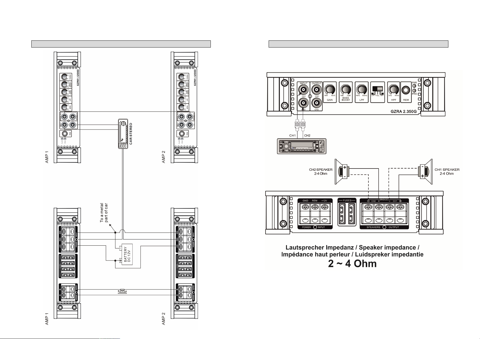
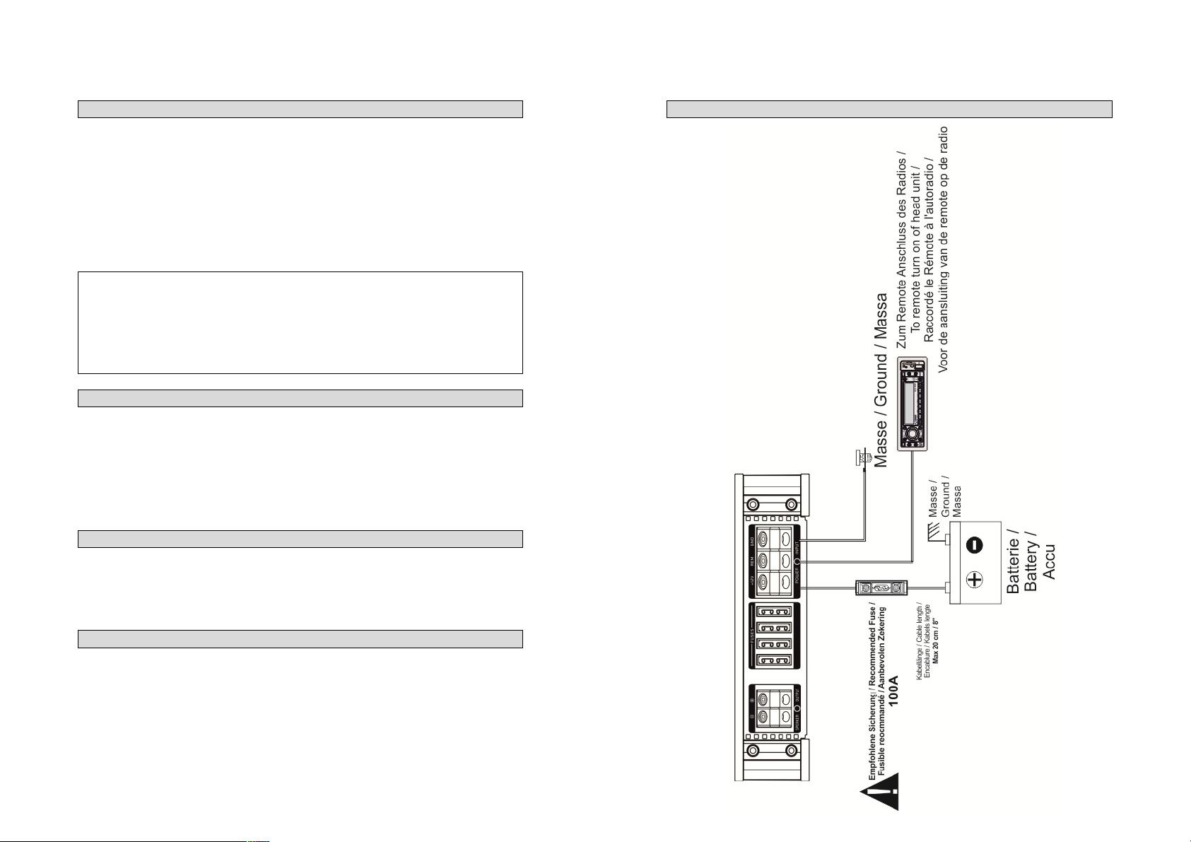
Stromanschluss – GZRA 1.1200D

5
6
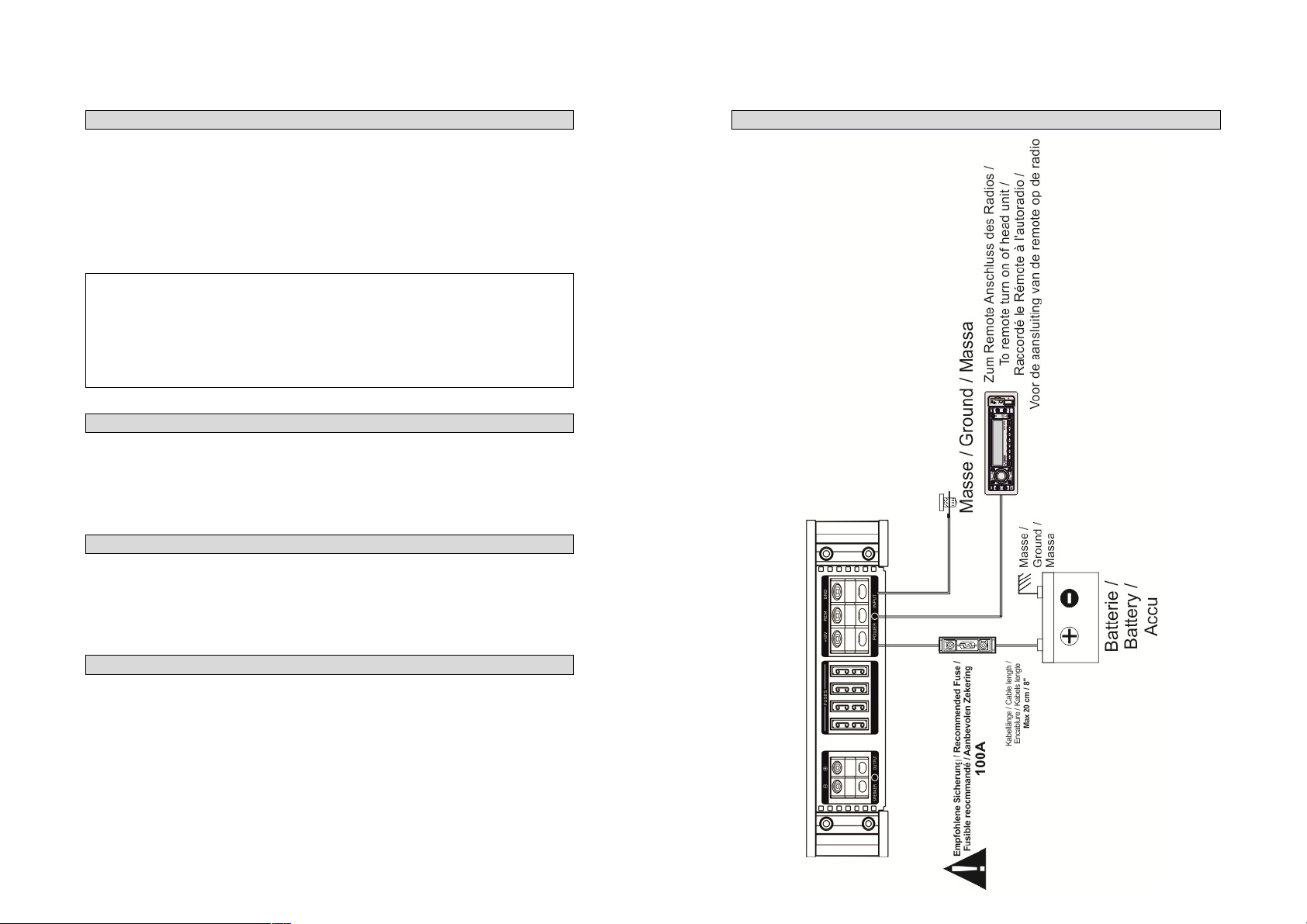
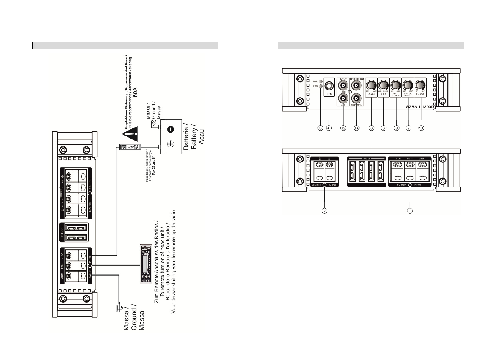
Stromanschluss – GZRA 2.350G
Einstellungen und Funktionen – GZRA 1.1200D
7
8
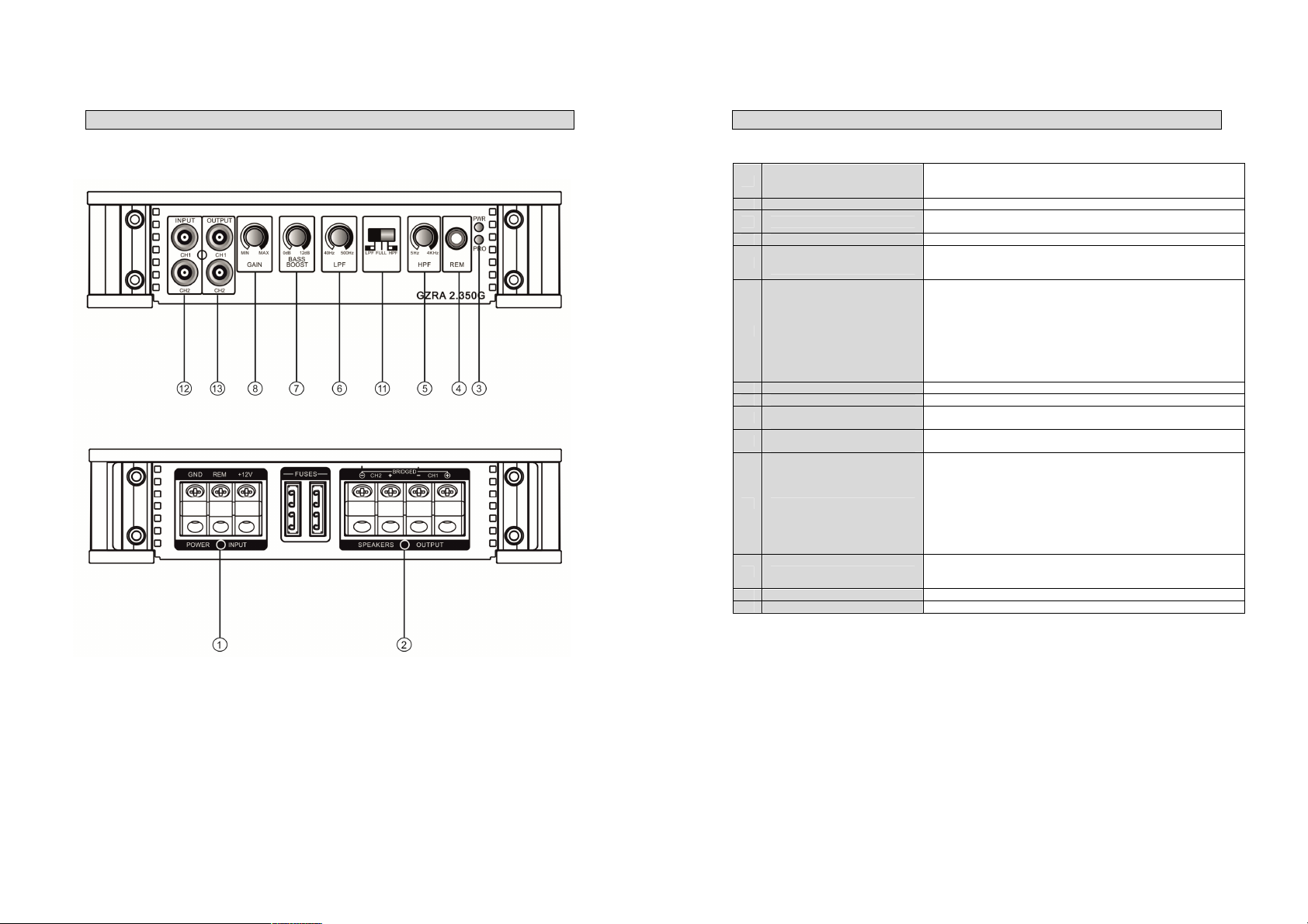
Einstellungen und Funktionen – GZRA 2.350G
Einstellungen und Funktionen
Stromanschluss
1
2 Lautsprecheranschlüsse Zum Anschluss der Lautsprecher
3 Zustandsanzeige
4 Remote Control Eingang Zum Anschluss des Bass Lautstärkereglers.
High Pass Regler
5
(Subsonic)
6 Low Pass Regler
7 Bass Boost Regler Zum Einstellen des Bass Boost Levels im Bereich von 0 bis +12 dB.
8 Gain Regler Mit diesem Regler regulieren Sie die Eingangsempfindlichkeit.
Subsonic Regler
9
(GZRA 1.1200D)
Phase Shift Regler
10
(GZRA 1.1200D)
11 Mode Schalter
12 Input
13 Output Zum Anschluss weiterer Verstärker.
14 Linkmode Zum Anschluss im Linkmodus
GND -> Masse Anschluss
REM -> Remote Antennenanschluss
BATT -> +12 Volt
GRÜN – OK
ROT – Fehler
Setzen Sie den Filter - Schalter auf “HIGH”. Justieren Sie die variable
HPF Übergangsfrequenz mit dem Regler auf die gewünschte Frequenz. Es
werden alle Frequenzen unterhalb 5 – 4000 Hz gefiltert.
Für Subwoofer- und Kickwooferbetrieb -
Es werden nur noch Frequenzen unterhalb von 40 – 500 Hz (GZRA
2.350G) oder 30 – 250 Hz (GZRA 1.1200D) wiedergegeben (abhängig
von der Reglerstellung des LPF Filters). Setzen Sie den Filter - Schalter
auf “LOW”. Justieren Sie die variable LPF Frequenz mit dem Regler auf
die gewünschte Frequenz.
Bei der LPF-Einstellung ist ebenfalls der Highpass (Subsonic) aktiviert.
Dies entspricht einem Bandpass Filter von 5 – 500 Hz (GZRA 2.350G)
Zum Einstellen des Subsonic Filters im Bereich von 5 bis 50Hz.
Dieser Regler / Schalter erlaubt Ihnen, den Subwoofer phasenrichtig an
das Frontsystem anzupassen.
Stellen Sie die Weiche für die ausgewählte Anwendung ein.
LPF - Nur tiefe Frequenzen 40 – 500 Hz (GZRA 2.350G) werden
wiedergegeben.
FULL - Alle Frequenzen werden übertragen.
HPF - Nur mittlere und hohe Frequenzen (über 5 Hz – 4000 Hz) werden
übertragen.
Bei der LPF-Einstellung ist ebenfalls der Highpass (Subsonic) aktiviert.
Dies entspricht einem Bandpass Filter von 5 - 500 Hz (GZRA 2.350G)
An diesen Anschlüssen schließen Sie die Cinchleitungen an.
Um Störungen zu vermeiden, verwenden Sie bitte hochwertige
Cinchkabel.
9
Frequenz
Spule
Kondensator
80 Hz
7,5 mH
470 uF
100 Hz
6,5 mH
330 uF
120 Hz
5,5 mH
370 uF
150 Hz
4 mH 220 uF
10
Einschalten des Verstärkers
Der Verstärker schaltet sich automatisch einige Sekunden nach dem Einschalten des Radios ein.
Achtung: Ihr Verstärker schaltet sich zeitweise aus, wenn er überhitzt ist, schaltet sich jedoch nach der Abkühlung
automatisch wieder ein (ca. 80° C).
Einstellung des Audiopegels
1. LEVEL (MIN/MAX): mit Linksdrehung ganz auf MIN drehen
2. Drehen Sie die Lautstärke am Radio auf ungefähr 1/3 der Höchstlautstärke
3. Stellen Sie am LEVEL- Regler eine angenehme Lautstärke ein
Lautsprecher Anschluss für Trimode Betrieb – Bemerkungen
Der Trimodebetrieb ermöglicht es, einen Subwoofer Mono zu betreiben, während die Hauptlautsprecher in
Stereobetrieb laufen. Bitte den Weichenschalter auf „Full“ – Stellung belassen.
Benutzen Sie 100 V bipolare Kondensatoren für die Hochpassweichen, um tiefe Frequenzen wegzufiltern und Luft-
oder Kernspulen mit einem Drahtdurchmesser von mind. 1mm für die Lowpassweiche, um die hohen Frequenzen
zu blockieren.
Die Kondensator- und Spulenwerte können Sie den der unten stehenden Tabelle entnehmen, die Front- und
Rearkanäle des Verstärkers nehmen diese Werte an. In den folgenden Bildern werden nur die hinteren linken und
rechten Kanäle gezeigt.
Werte für 6dB Passivweiche
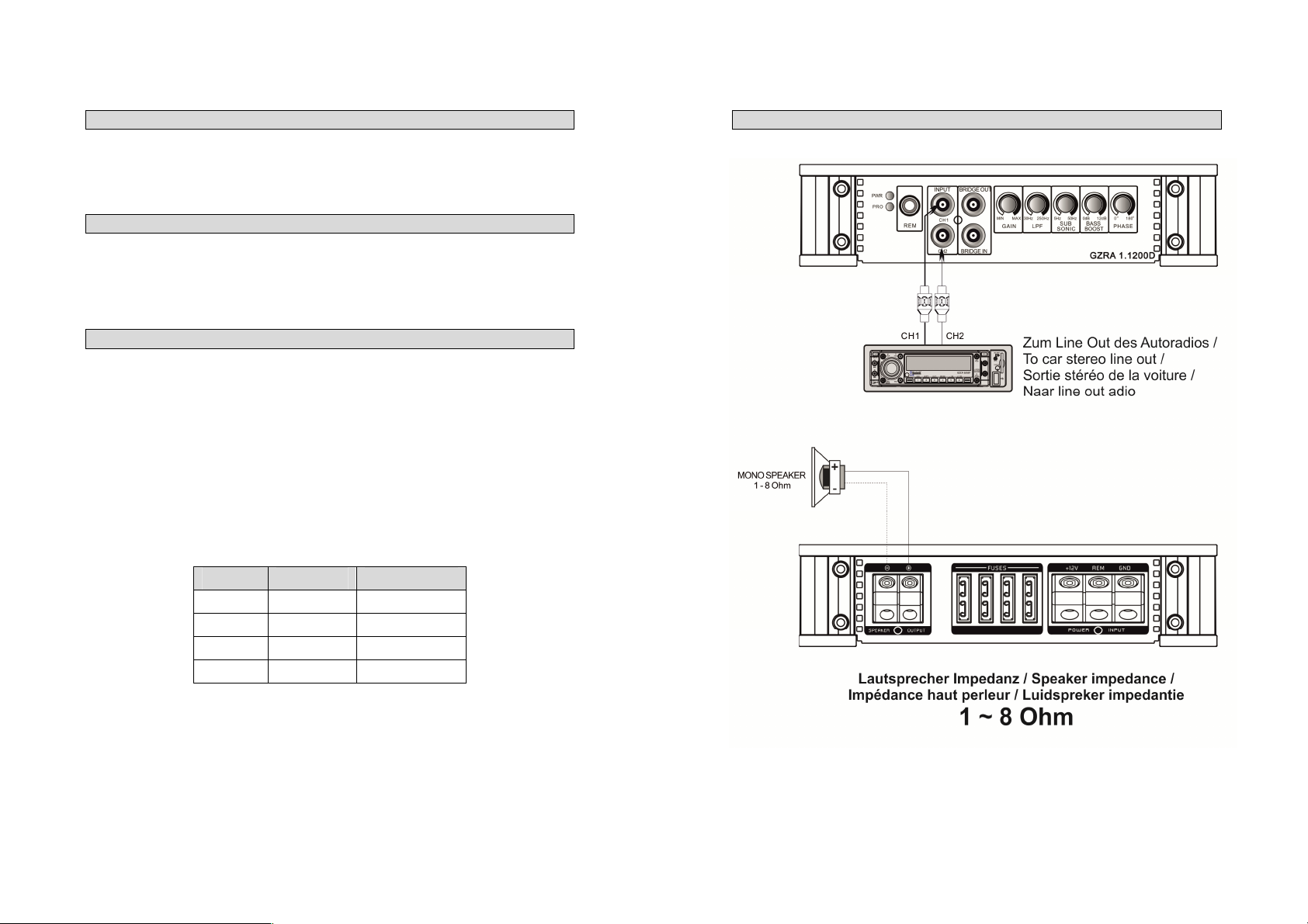
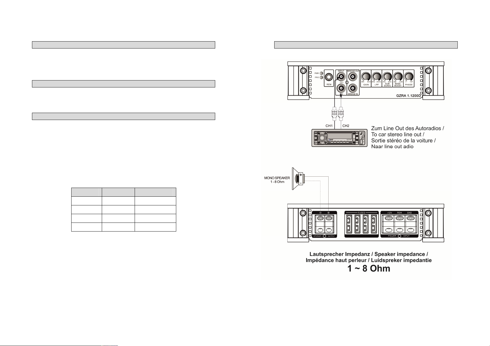
Stereo Anschluss – GZRA 1.1200D
11
12
Linkmodus Anschluss – GZRA 1.1200D
Stereo Anschluss – GZRA 2.350G
13
14
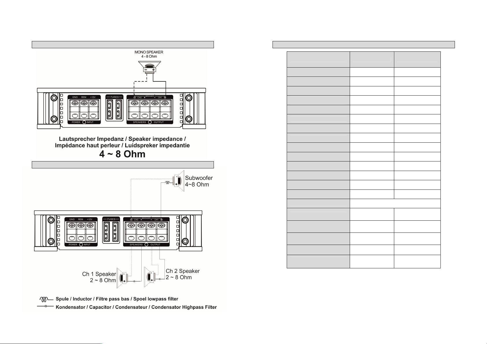
Mono Anschluss – GZRA 2.350G
Trimode Betrieb – GZRA 2.350G
Technische Daten
Model GZRA 1.1200D GZRA 2.350G
Typ
RMS Power @ 4 Ω
CEA Standard CEA-2006-A
RMS Power @ 2 Ω
CEA Standard CEA-2006-A
RMS Power @ 1 Ω
CEA Standard CEA-2006-A
RMS Power @ 4Ω Gebrückt
CEA Standard CEA-2006-A
Dämpfungsfaktor
Signal to noise Ratio
Tiefpass Weiche
Hochpass Weiche
Bandpass Weiche
Subsonic Filter
Bass boost
Phase shift
Frequenzgang
Eingangsempfindlichkeit
Stereo Cinch-Ausgang
Bass-Pegelfernbedienung
Sicherung
Abmessungen
B x H x L mm
Abmessungen
B x H x L inch
1 Kanal Class D 2 Kanal Class G
1 x 500 W
1 x 590 W
1 x 1000 W
1 x 1300 W
1 x 1600 W
(1% THD+N)
(10% THD+N)
1 x 850 W
(1% THD+N)
(10% THD+N)
(1% THD+N)
(10% THD+N)
--
> 100 > 150
> 80 dB > 90 dB
30 Hz – 250 Hz 40 Hz – 500 Hz
-- 5 Hz – 4000 Hz
5 Hz – 250 Hz 5 Hz – 500 Hz
5 Hz – 50 Hz --
0 ~ +12 dB (45 Hz) 0 ~ +12 dB (45 Hz)
0 – 180° --
5 Hz – 250 Hz
(± 1 dB)
200 mV – 10 V (± 5%)
4 x 30A 2 x 35A
340 x 45 x 190 350 x 45 x 190
13.4“ x 1.77“ x 7.5“ 13.78“ x 1.77“ x 7.5“
2 x 240 W
2 x 370 W
1 x 740 W
2 x 200 W
2 x 320 W
1 x 640 W
5 Hz – 38 KHz
(± 1 dB)
(1% THD+N)
(10% THD+N)
(1% THD+N)
(10% THD+N)
--
(1% THD+N)
(10% THD+N)
15
16
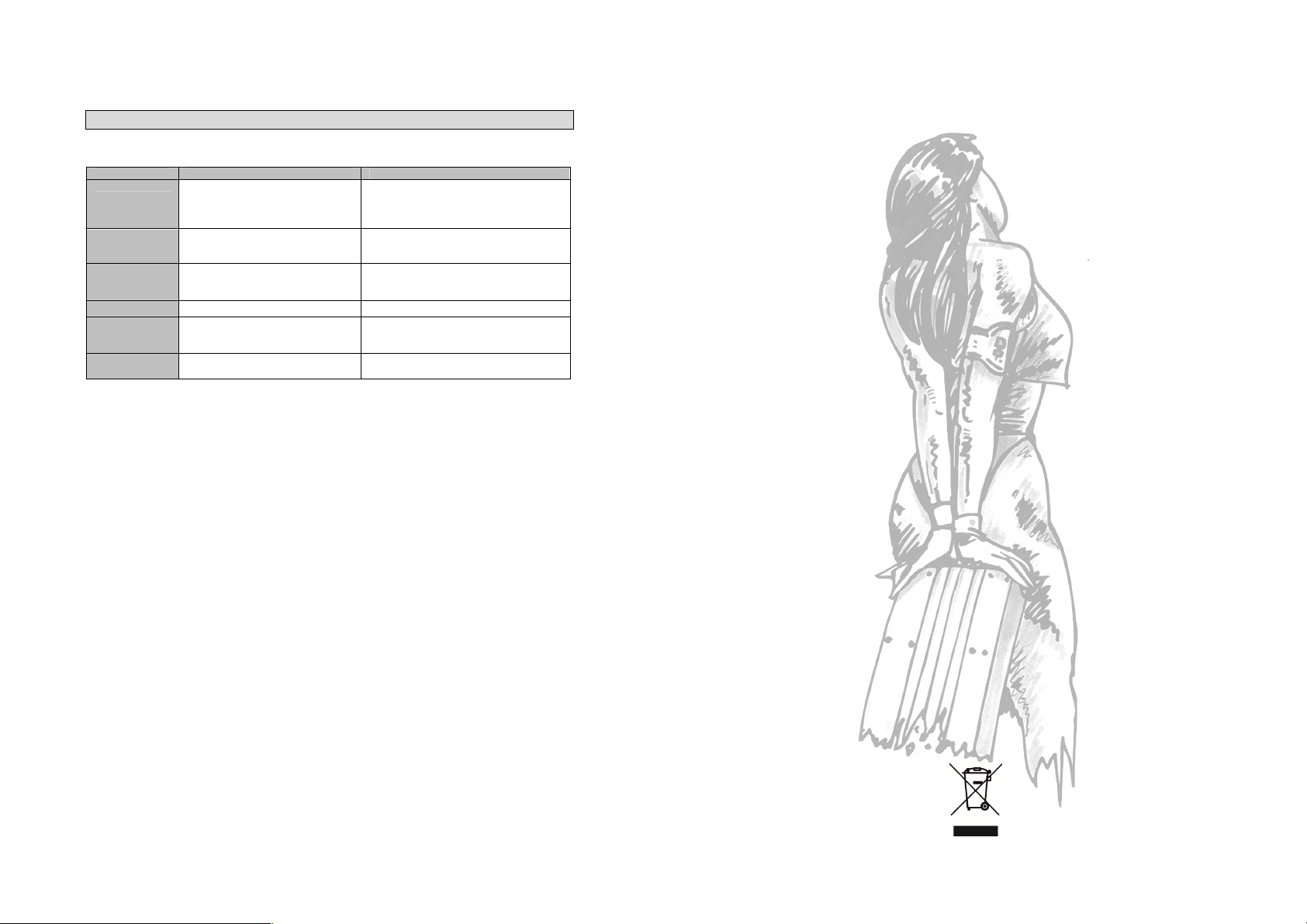
Wenn irgendetwas nicht funktioniert
Problem Kontrolle Hilfe
Kein Ton Leuchtet die PWR LED? Sicherung prüfen
Leuchtet die PROT LED? Kurzschluss am Lautsprecher
Verstärker
schaltet nicht ein
Keine Spannung am Remote Remote am Radio prüfen
Verstärker
schaltet bei
Lautstärke ab
Ton fehlt an
einem Kanal
Keine Stromzufuhr Sicherung prüfen
Lautsprecherimpedanz prüfen Prüfen Sie, ob der Widerstand am LS Terminal
Cinch / Lautsprecherkabel prüfen Kabel/Stecker beschädigt
Remote Kabel prüfen
+12 Volt prüfen
Masse prüfen
Gerät überhitzt
Gerät defekt
+12Volt prüfen
Masse prüfen
von 1 Ohm nicht unterschritten wird
Die Gewährleistung entspricht der gesetzlichen Regelung. Eine Rücksendung kann nur nach
vorheriger Absprache und in der Originalverpackung erfolgen. Bitte unbedingt einen maschinell
erstellten Kaufbeleg und eine Fehlerbeschreibung beilegen. Von der Gewährleistung
ausgeschlossen sind Defekte, die durch Überlastung, unsachgemäße Behandlung oder bei
Limited warranty - defective products must be returned in original packaging - please add a copy
of the original purchasing invoice showing the purchasing date and a detailed description of the
failure. Failure caused by overload, misuse or by using the product for competition purpose are
De Garantie bepalingen van alle door ground zero geleverde producten is volgens wettelijke
bepalingen geregeld, Een retourzending kan alleen na duidelijke afspraak en in de originele
verpakking plaatsvinden.SVP een aankoopbon en een duidelijke storingsomschrijving
bijvoegen.Van garantie uitgesloten zijn defecten door overbelasting, onkundig gebruik, of door
La garantie est conforme aux droits légaux. Un retour du produit défectueux doit être dans son
emballage d'origine sur présentation du reçu ou de la facture indiquant la description du
defaut.La présente Garantie n'est pas applicable lorsque le produit a été endommagé en raison:
Mauvaise alimentation, Trop de puissance (HP,Subwoofer) Accident, Installation ou Utilisation non
Teilnahme an Wettbewerben entstanden sind.
not covered by the warranty.
deelname aan wedstrijden (SPL) ontstaan zijn.
conforme aux normes Technique (Concours SPL etc).
GROUND ZERO GmbH
Erlenweg 25; D - 85658 Egmating, Germany
Tel. +49 (0)8095/873 830 Fax -8310
www.ground-zero-audio.com
Wir behalten uns das Recht vor, zukünftig nötige Änderungen oder Verbesserungen an dem
Produkt vorzunehmen ohne den Kunden darüber zu informieren.
We reserve the right to make needed change or improvement to the product without informing
customer about this in advance.
Wij behouden ons het recht om de nodige veranderingen of verbeteringen aan het product door
te voeren zonder de klant hierover te informeren.
Nous nous réservons le droit d'entreprendre à l'avenir nécessairement des modifications ou des
améliorations au produit sans informer le client.
2
PLEASE READ BEFORE INSTALLATION
We are providing a helpful hints list which should keep you from experiencing
Amplifier
Owner’s Manual
RADIOACTIVE
GZRA 1.1200D
GZRA 2.350G
unnecessary shut down. Have fun with this high quality Titanium product.
Features
• Modern Class G technology (GZRA 2.350G)
• Efficiency Class D technology (GZRA 1.1200D)
• 4 Ohm / 2 Ohm stable Stereo (GZRA 2.350G)
• 1 Ohm stabile & linkable (GZRA 1.1200D)
• Mosfet power supply
• Power & Protection indicator
• Variable 12dB bass boost (45Hz)
• Variable highpass (subsonic)
• Variable lowpass
• Adjustable input sensitivity
• Soft delayed remote turn- on
• Bass remote control
• Thermal / Short / Overload protection
Tools and materials you need
• Screwdriver
• Electric drill, 3 mm / 0.12” carbide drill bit
• Mounting screws
• Power wire min. 20 mm²
• Ground wire min. 20 mm²
• Speaker wire min. 2 x 2,5 mm²
Thank you for selecting a Ground Zero amplifier.
3
4
Please note!
• As a precaution it is advisable to disconnect the vehicle’s battery before making connection
to the +12 Volts supply wiring (see owner’s manual of your car for further information).
• Please use great caution drilling your trunk. Your gas tank and brake lines can be damaged by
puncturing with your drill bit – this could cause damage or failure of your cars operating systems.
• Never pass wires over sharp angles. It is recommended to buffer the power supply of the amplifier
with a capacitor min. 1 Farad to guarantee a stable operation voltage.
WARNING !
High powered audio systems in a vehicle are capable of generating "Live Concert" levels of sound pressure.
Continued exposure to excessively high volume sound levels may cause hearing loss or damage. Also, operation
of a motor vehicle while listening to audio equipment at high volume levels may impair your ability to hear
external sounds such as; horns, warning signals, or emergency vehicles, thus constituting to a potential traffic
hazard. In the interest of safety, Consumer Electronics recommends listening at lower volume levels while driving.
Planning your system
Before beginning the installation, consider the following:
a. If you plan to expand your system by adding other components sometime in the future, ensure
adequate space is left, and cooling requirements are met.
b. If your radio / source is equipped with pre-amp outputs, it is possible to utilize them to drive the
amplifier and connecting (amplifier) to the 2 rear speakers.
Mounting your amplifier
a. Select a suitable location that is convenient for mounting, is accessible for wiring
and has ample room for air circulation and cooling.
b. Use the amplifier as a template to mark the mounting holes, remove the amplifier.
Warning
Chose a mounting position where all eclectic wires are protected from being damaged by sharp edges, heat or
other conditions. +12Volt DC electrical connections must be fused on the battery side. Make sure your radio and
all other devices will be turned off while connection your system.
If you need to replace the power fuse, replace it only with a fuse identical to that supplied with the system. Using
a fuse of different type or rating may result in damage to this system which isn’t covered by the warranty.
Power supply – GZRA 1.1200D
5
6
Power supply – GZRA 2.350G
Controls and functions – GZRA 1.1200D

7
8
Controls and functions – GZRA 2.350G
Controls and functions
Power terminals
1
2 Speaker terminals For connection of the speakers
3 Satus indication
4 Remote control input For connection of the bass remote control.
High pass controller
5
(Subsonic)
6 Low pass controller
7 Bass boost controller For adjusting of the bass boost level in the range from 0 to +12 dB.
8 Input level controller With this controller you can adjust the input sensitivity.
Subsonic controller
9
(GZRA 1.1200D)
Phase Shift Regler
10
(GZRA 1.1200D)
11 Mode Schalter
12 Cinch inputs
13 Output For connection of additional amplifiers.
14 Linkmode For connection in linkmode
GND -> Ground connection
REM -> Remote antenna terminal
BATT -> +12 Volt
GREEN – OK
RED – Error
Set the filter switch to „HIGH“ position.
Adjust the variable HPF crossover frequency to the desired frequency
using the controller. All frequency between 5 and 4000Hz will be
reproduced.
For subwoofer and Kickwoofer operation -
Only frequencies from 40 – 500 Hz (GZRA 2.350G) or 30 – 250 Hz
(GZRA 1.1200D) (depending on the LPF filter controller position). Set the
filter switch to „LOW“ position. Adjust the variable LPF frequency to the
desired frequency using the controller.
At LPF adjustment, also the Highpass (Subsonic) is activated.
This equals a Bandpass filter of 5 – 500 Hz (GZRA 2.350G).
For adjustment of the subsonic filter in a range of 5 – 50 Hz.
This controller allows you to fit the subwoofer channel in-phase to the
front system.
Adjust the crossover for the chosen utilization.
LPF – Only bass frequencies below 40 – 500 Hz (GZRA 2.350G) will be
reproduced.
FULL – All frequencies will be reproduced.
HPF – Only middle and high frequencies (over 5Hz – 4000Hz) will be
reproduced.
At LPF adjustment, also the Highpass (Subsonic) is activated.
This equals a Bandpass filter of 5 - 500 Hz (GZRA 2.350G).
Terminal for connection of the RCA wires.
To avoid failure, please use high quality RCA wires.
9
Frequency
Indu
ctor Capacitor
80 Hz
7,5 mH
470 uF
100 Hz
6,5 mH
330 uF
120 Hz
5,5 mH
370 uF
150 Hz
4 mH 220 uF
10
Turning on the amplifier
The amplifier automatically turns on a few seconds after you turn on your radio.
Note: Your amplifier temporarily shuts down if it gets too hot, then restarts automatically once it cools
(At about 80° / 176° F).
Adjusting the audio level
1. LEVEL (Min/Max): Turn fully counter- clockwise to MIN position
2. Turn the auto sound system's volume control to about two-third of its full range.
3. Adjust LEVEL to a comfortable listening level.
Connecting the speaker for trimode operation - notes
TRI MODE operation output allows a subwoofer to be operated in mono mode while the main speakers are
playing in stereo. Leave the crossover switch on “Full” position.
Use 100 volt, non-polar capacitors for a high pass crossover to filter out low frequencies and Air- core or
Ferrit- ore coils with a minimum diameter of 1 mm / 0.039” for the lowpass crossover to filter out high
frequencies.
The capacitor and inductor values as written in the below table. The front and rear channels of this amplifier get
this capability. Only the rear left and right channels are shown on the following pictures.
Values for 6dB passive crossover
Stereo wiring – GZRA 1.1200D

11
12
Linkmode wiring – GZRA 1.1200D
Stereo wiring – GZRA 2.350G

13
14
Mono wiring – GZRA 2.350G
Trimode operation – GZRA 2.350G
Specifications
Model GZRA 1.1200D GZRA 2.350G
Type
RMS Power @ 4 Ω
CEA Standard CEA-2006-A
RMS Power @ 2 Ω
CEA Standard CEA-2006-A
RMS Power @ 1 Ω
CEA Standard CEA-2006-A
RMS Power @ 4Ω Bridged
CEA Standard CEA-2006-A
Damping factor
Signal to noise Ratio
Lowpass
Highpass
Bandpass
Subsonic filter
Bass boost
Phase shift
Frequency response
Input sensitivity
Stereo RCA-out
Bass remote control
Fuse
Dimensions
W x H x L mm
Dimensions
W x H x L inch
1 channel class D 2 channel class G
1 x 500 W
1 x 590 W
1 x 1000 W
1 x 1300 W
1 x 1600 W
(1% THD+N)
(10% THD+N)
1 x 850 W
(1% THD+N)
(10% THD+N)
(1% THD+N)
(10% THD+N)
--
> 100 > 150
> 80 dB > 90 dB
30 Hz – 250 Hz 40 Hz – 500 Hz
-- 5 Hz – 4000 Hz
5 Hz – 250 Hz 5 Hz – 500 Hz
5 Hz – 50 Hz --
0 ~ +12 dB (45 Hz) 0 ~ +12 dB (45 Hz)
0 – 180° --
5 Hz – 250 Hz
(± 1 dB)
4 x 30A 2 x 35A
340 x 45 x 190 350 x 45 x 190
13.4“ x 1.77“ x 7.5“ 13.78“ x 1.77“ x 7.5“
200 mV – 10 V (± 5%)
2 x 200 W
2 x 240 W
2 x 320 W
2 x 370 W
1 x 640 W
1 x 740 W
5 Hz – 38 KHz
(± 1 dB)
(1% THD+N)
(10% THD+N)
(1% THD+N)
(10% THD+N)
--
(1% THD+N)
(10% THD+N)
 Loading...