

Page 1

? IMPORTANT INFORMATION ? KEEP FOR OPERATOR ? IMPORTANT INFORMATION ?
OPERATOR MANUAL OM-NEB/1
Part Number 121012 DOMESTIC
Model: NEB/1
Steam Boilers
Electrically Heated
24, 36 or 48 Kilowatts
THIS MANUAL MUST BE RETAINED FOR FUTURE REFERENCE. READ,
UNDERSTAND AND FOLLOW THE INSTRUCTIONS AND WARNINGS
CONTAINED IN THIS MANUAL.
WARNING
DO NOT STORE OR USE GASOLINE OR OTHER FLAMMABLE VAPORS AND
LIQUIDS IN THE VICINITY OF THIS OR ANY OTHER APPLIANCE.
Information contained in this document is
known to be current and accurate at the time
of printing/creation. Unified Brands recommends referencing our product line websites,
unifiedbrands.net, for the most updated
product information and specifications.
Page 2

OM-NEB/1
IMPORTANT — READ FIRST — IMPORTANT
CAUTION: SHIPPING STRAPS ARE UNDER TENSION AND CAN SNAP BACK WHEN CUT.
CAUTION: UNIT WEIGHS 620 LB (282 KG) FOR SAFE HANDLING, INSTALLER SHOULD
OBTAIN HELP, OR EMPLOY APPROPRIATE MATERIALS HANDLING
EQUIPMENT (FORKLIFT, DOLLY, OR PALLET JACK) TO REMOVE THE UNIT
FROM THE SKID AND MOVE IT TO ITS PLACE OF INSTALLATION..
WARNING: THE UNIT MUST BE INSTALLED BY PERSONNEL WHO ARE QUALIFIED TO
WORK WITH ELECTRICITRY AND PLUMBING. IMPROPER INSTALLATION
COULD RESULT IN INJURY TO PERSONNEL AND/OR DAMAGE TO
EQUIPMENT.
CAUTION: DRAIN MUST BE RATED FOR STEAM AND BOILING WATER. DO NOT USE
PLASTIC PIPE.
WARNING: DO NOT CONNECT THE BOILER DRAIN DIRECTLY TO A BUILDING DRAIN.
WARNING: BLOCKING THE DRAIN MAY BE HAZARDOUS.
IMPORTANT: Improper drain connection will void warranty.
WARNING: ALLOW COOKING CHAMBERS TO COOL BEFORE CLEANING.
WARNING: CAREFULLY READ THE WARNINGS AND FOLLOW THE DIRECTIONS ON THE
LABEL OF EACH CLEANING AGENT. USE SAFETY GLASSES AND RUBBER
GLOVES AS RECOMMENDED BY DELIMING AGENT MANUFACTURER.
WARNING: DO NOT MIX DE-LIMING AGENTS (ACID) AND DE-GREASERS (ALKALI) IN THE
STEAM GENERATOR OR ON THE COOKING CHAMBER WALLS.
NOTICE: Do not use a cleaning or de-liming agent that contains any sulfamic acid or
any chloride, including hydrochloric acid (HCl). If the chloride content of any
product is unclear, consult the manufacturer. Do not use a de-greaser that
contains potassium hydroxide or sodium hydroxide or that is highly alkaline.
WARNING: USE OF REPLACEMENT PARTS OTHER THAN THOSE SUPPLIED BY GROEN
OR AUTHORIZED DISTRIBUTORS VOIDS ALL WARRANTIES AND CAN CAUSE
BODILY INJURY TO THE OPERATOR AND DAMAGE THE EQUIPMENT.
SERVICE PERFORMED BY OTHER THAN FACTORY-AUTHORIZED
PERSONNEL WILL VOID ALL WARRANTIES.
WARNING: HIGH VOLTAGE EXISTS INSIDE CONTROL COMPARTMENTS. DISCONNECT
FROM BRANCH BEFORE SERVICING. FAILURE TO DO SO CAN RESULT IN
SERIOUS INJURY OR DEATH.
WARNING: DO NOT EXPOSE SKIN TO ESCAPING STEAM. SEVERE BURNS CAN RESULT.
2
Page 3

OM-NEB/1
Table of Contents
OPERATOR WARNINGS .................................................................... 2
EQUIPMENT DESCRIPTION ................................................................. 4
INSPECTION AND UNPACKING .............................................................. 4
WATER CONDITIONING REQUIREMENTS ..................................................... 5
INSTALLATION INSTRUCTIONS .............................................................. 5
INITIAL START-UP ......................................................................... 7
OPERATING INSTRUCTIONS ................................................................ 8
SEQUENCE OF OPERATION ................................................................. 8
CLEANING ................................................................................ 9
MAINTENANCE ........................................................................... 11
TROUBLESHOOTING ...................................................................... 12
PARTS LIST .............................................................................. 14
SCHEMATICS ............................................................................ 17
REFERENCES ............................................................................ 20
SERVICE LOG ............................................................................ 21
NOTES .................................................................................. 22
WARRANTY PROTECTION ................................................................. 23
[SEE OM-HY-6CAV FOR STEAMER CAVITY OPERATION AND/OR OM-TD FOR KETTLE OPERATION.]
The NEB-1 Boiler may be used for a variety of applications in a variety of combinations.
3
Page 4
OM-NEB/1
Equipment Description
The Groen NEB/1 steam boiler generates low
pressure steam for use with HyPlus cabinet-mounted
steamers and steam jacketed kettles.
The boiler is housed in a stainless steel cabinet.
Various combinations of steam-operated kettles and
steamers can be mounted on the top. The boiler is
small enough to fit in a 24-1/8” (613 mm) wide by
34-3/16" (868 mm) deep by 29-3/16" (741 mm) tall
(maximum) cabinet.
The boiler is constructed of 1/4" thick steel, which is
certified by the American Society of Mechanical
Engineers (ASME) for pressure vessels. All welds
are hydrostatically tested.
Inspection and Unpacking
The unit will arrive completely assembled, wrapped
in protective plastic and in a heavy-duty carton on a
skid. Immediately on receipt examine the carton and
unit for shipping damage. Report any damage or
incorrect shipments to the delivery agent.
Write down the model number, serial number and
installation date of your unit, and keep this
information for future reference. Space for these
entires is provided at the top of the Service Log on
Page 21 of this manual.
The boiler is also equipped with all required
instruments, fittings, and controls.
Heating elements with low watt density ensure longer
life for the unit. The boiler is available for three
phase 60 Hertz service in the following voltage and
power combinations:
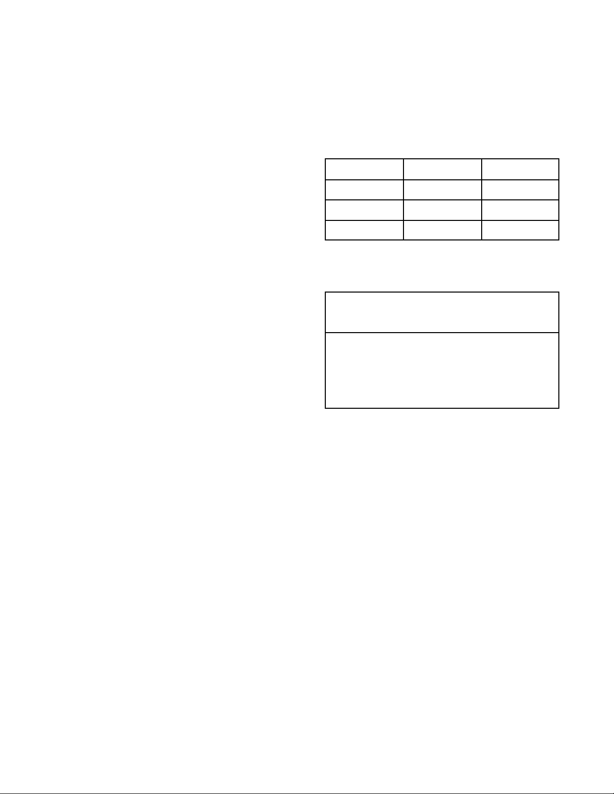
208 Volts 240 Volts 480 Volts
24 Kilowatt 24 Kilowatt 24 Kilowatt
36 Kilowatt 36 Kilowatt 36 Kilowatt
48 Kilowatt 48 Kilowatt 48 Kilowatt
CAUTION
SHIPPING STRAPS ARE UNDER TENSION AND
CAN SNAP BACK WHEN CUT.
UNIT WEIGHS 620 LB (282 KG) OR MORE.
FOR SAFE HANDLING OBTAIN HELP, OR USE
MATERIALS HANDLING EQUIPMENT (FORK
LIFT, DOLLY OR PALLET JACK) TO REMOVE
THE UNIT FROM THE SKID AND MOVE IT TO
ITS PLACE OF INSTALLATION.
When installation is to start, cut the straps and lift the
unit straight up off the skid.
Unit will arrive in a heavy carton,
mounted on a skid.
Beneath the heavy carton, the unit
will be wrapped in protective
plastic on a heavy skid.
4
Page 5

Water Conditioning
OM-NEB/1
It is essential that the boiler be supplied with water
that will not form scale at an unacceptable rate. The
boiler was engineered to minimize scale, but its
formation depends on water hardness and how
much the unit is used.
In some areas of the United States the water is low
enough in mineral content to avoid scale build-up.
However, most water supplies carry heavy loads of
minerals. This will form scale on the boiler, reduce
its steam output, and possibly cause premature
component failure.
Your water utility can tell you about the minerals in
your water. The water going to the steam generator
should have between 1 and 30 parts per million total
dissolved solids (TDS) and should have a pH (acidity
rating) of 7.0 or higher.
Please follow these simple precautions:
1. Do not rely on unproven water treatment
equipment which is sold for scale prevention or
scale removal. It frequently won’t work. The
best way to prevent scale is to supply the purest
possible water.
3. Installing a water meter between the softener
and the steamer will provide an accurate gauge
of water use, and will help determine when to
exchange cartridges or regenerate the softener.
Using a water softener will provide longer
generator life, higher steam capacity, and reduce
maintenance requirements.
4. If you notice a slowdown in steam production,
check the boiler for scale build-up. Heavy scale
reduces the unit’s ability to boil water, and can
even cause heating elements in the steam
generator to overheat and burn out.
5. Groen gas and electric pressure boilers are also
available with two separate water intakes:
one for the boiler (soft water)
one for the spray condenser (untreated water).
The steam generator only uses 14 to 31% of a
steamer’s water. Since softener systems are
typically sized by total GPH (gallons per hour),
the second intake could reduce treatment
requirements by up to 80%, resulting in
significant savings.
2. If your water contains scale-forming minerals, as
most water does, use a well-maintained water
softener. Whether an exchangeable softener
cartridge or a regenerating system is chosen, a
regular exchange system is essential.
Reduce scale problems by using and
maintaining a water softener for your
steamer!
Installation
WARNING
THE UNIT MUST BE INSTALLED BY PERSONNEL WHO ARE QUALIFIED TO WORK WITH
ELECTRICITY AND PLUMBING. IMPROPER INSTALLATION CAN CAUSE INJURY TO
PERSONNEL AND/OR DAMAGE TO THE EQUIPMENT.
Getting Started
WHEN THE UNIT IS RECEIVED, IMMEDIATELY
INSPECT IT FOR EXTERNAL OR INTERNAL
DAMAGE. REPORT ANY DAMAGE TO THE
FREIGHT CARRIER.
NOTE: A RETROFIT KIT IS AVAILABLE FROM
THE FACTORY FOR THOSE LOCALITIES IN
WHICH COMPLIANCE WITH CSD-1 STANDARDS
IS REQUIRED.
*In order to service the unit properly, access with
at least 24 inches clearance is needed on the
right side.
Level the unit front to rear and left to right by
adjusting its legs. Levelness may be checked by
using a spirit level on top of the cabinet.
Right Side — Two inches*
Left Side — Four inches
Rear — Six inches
After inspection, keep the unit in its shipping
container until it is installed. It can be installed on
combustible and non-combustible floors. Minimum
clearances are:
CAUTION
MAKING ANY ELECTRICAL OR MECHANICAL
CHANGE IN THE UNIT WITHOUT PRIOR GROEN
APPROVAL WILL VOID ALL WARRANTIES.
5
Page 6

OM-NEB/1
1. Electrical Supply Connection
Provide the proper voltage (60 Hz, Three Phase) as
specified on the electrical information plate attached
to the unit. The current draw and minimum
recommended wire size and insulation temperature
ratings are shown in the table below. Use only
copper wire. Local codes and/or the National
Electrical Code should be followed (ANSI/NFPA-701987 - or latest edition).
AN ELECTRICAL GROUND IS REQUIRED. The
ground terminal is located next to the supply terminal
block in the electrical enclosure. The main supply
knockout hole is sized for a 1½” conduit fitting. The
auxiliary supply knockout is sized for a ¾” conduit
fitting. Copies of the electrical schematic are located
in the electrical enclosure on the equipment and in
this manual. In Canada, electrical service must
comply with the Canadian Electrical Code, CSA
C22.1, Part 1, and/or local codes.
Voltage
208 24 67 2 6.5 8 3.3 90oC
208 36 100 2/0 9.3 6 4.1 90oC
208 48 100 (Main)
240 24 58 3 5.8 8 3.3 90oC
240 36 87 1 7.3 8 3.3 90oC
240 48 87 (Main)
480 24 29 3
480 36 44 1/0
480 48 58 2/0
Power Rating
(Kilowatt)
Current Draw
(Ampere)
34 (Auxiliary)
29 Auxiliary)
2. Water Connection
a. Cold water is supplied via a ½" NPT pipe
connection at the rear of the unit. A check valve
(back siphonage device) must be installed in
accord with local plumbing codes.
a. Water pressure should be between 30 and 60
PSI (215 and 420 kPa). If it is over 60 PSI (420
kPa), a pressure regulator is required. A strainer
screen at the connection is also recommended,
to trap any debris before it can enter the system.
c. The NEB/1 boiler uses water at the maximum
rate per hour shown below.
Maximum Water Consumption
Unit Gallons/Hour Liters/Hour
NEB/1 (24 KW) 8.2 31
NEB/1 (36 KW) 12.5 47.3
NEB/1 (48 KW) 16.9 64
Piping should be sized to handle total water
consumption.
Supply Wire Ground Wire
AWG mm AWG mm
2/0
6
1
8
8
6
3
9.3
4.1
7.3
3.3
5.8
3.3
8.3
4.1
9.3
5.8
6
10
6
10
10
10
10
10
8
8
4.1
2.6
4.1
2.6
2.6
2.6
2.6
2.6
3.3
3.3
3. Drain Connection
a. The drain connection is made at the rear of the
unit with 1¼" NPT pipe. DO NOT USE PLASTIC
PIPE. DRAIN PIPING MUST WITHSTAND
STEAM AND BOILING WATER. Extend the
drain piping to a nearby floor drain. Piping of
1¼" NPT (or 1½" NPT) is acceptable for
distances of six feet (2 m) or less. If the
distance to the drain is further than six feet (2
m), use 2" NPT piping.
b. The drain line must have a constant downward
pitch. Do not permit water traps in the line. DO
NOT CONNECT THE LINE DIRECTLY TO ANY
BUILDING DRAIN. There must be a vertical air
gap of at least two inches (5 cm) between the
drain line and the building drain unless otherwise
specified by local plumbing codes.
CAUTION
DO NOT LOCATE THE BOILER CABINET
DIRECTLY OVER A FLOOR DRAIN OR FLOOR
SINK. HUMIDITY OR WATER FROM A DRAIN
WILL DAMAGE ELECTRICAL PARTS.
IMPORTANT: Improper drain connection will
void warranty.
Rating
90oC
90oC
90oC
90oC
75oC
90oC
75oC
90oC
75oC
90oC
6
Page 7

4. Safety Valve
b. allows complete drainage of both the
Ensure that the safety valve (see picture, Page 11) is
vented properly. The following Installation Instruction
WARNING is quoted from the safety valve
manufacturer:
“During operation this valve may discharge large
amounts of steam and/or hot water. Therefore,
to reduce the potential for bodily injury and
property damage, a discharge line MUST be
installed that:
a. is connected from the valve outlet to a
safe point of discharge with no
intervening valve.
valve and the discharge line.
c. is independently supported and securely
anchored so as to avoid applied stress
on the valve.
d. is as short and straight as possible.
e. terminates freely to atmosphere where
any discharge will be clearly visible and
is at no risk of freezing.
f. terminates with a plain end which is not
threaded.
g. is constructed of a material suitable for
exposure to temperatures of 375oF or
greater
h. is, over its entire length, of a pipe size
equal to or greater than the valve outlet.”
Initial Start-Up
WARNING
ANY POTENTIAL USER OF THE EQUIPMENT SHOULD BE TRAINED IN SAFE AND CORRECT
OPERATING PROCEDURES.
OM-NEB/1
After the unit has been installed, test it to ensure that
it is operating properly.
1. Remove literature and packing material from the
interior and exterior of the unit.
2. Make certain the water supply is turned on.
3. Turn on electrical power to the unit.
4. Turn the ON/OFF switch on the cabinet front
panel to the “ON” position.
• The boiler drain valve will close and the unit
will fill with water.
• When the water level reaches the “mid”
probe, the red RESET light will come on.
• Push the START switch.
• The green light in the switch will come on
and the RESET light will go out. The heater
element contactors will close.
• When the water level reaches the “hi” probe,
the water supply to the boiler will shut off.
5. After about 15 minutes, the gauge pressure will
rise. When the pressure reaches 12 PSI (83
kPa), the main burner will turn off. Thereafter, as
pressure decreases, the contactors will close to
maintain the 12 PSI (83 kPa) level.
6. To shut the unit down, turn the ON/OFF switch to
OFF. When it has cooled to approximately
130oF, the unit will automatically drain.
If the unit functions as described above, it is ready
for use. If it does not, contact your authorized Groen
Service Agent.
7
Page 8

OM-NEB/1
Operation
WARNING
BE SURE ALL OPERATORS READ, UNDERSTAND AND FOLLOW THE OPERATING INSTRUCTIONS,
CAUTIONS AND SAFETY INSTRUCTIONS CONTAINED IN THIS MANUAL.
1. Controls
Operating controls are located on the front panel of
the unit.
a. The on/off switch starts the boiler or shuts it
off.
b. The RESET indicator lights to show that the
boiler has filled with water and that the
heater elements can close.
c. The start switch (momentary) closes the
heater element contactors. It also restarts
the unit if electrical power is interrupted, or if
a low water condition in the boiler disables
the unit.
2. Operating Procedure
a. Turn on the water supply to the unit.
b. Turn on electrical power to the unit.
c. Turn the ON/OFF switch on the front of the
cabinet to “ON.”
1) The boiler drain valve will close and the
unit will fill with water.
3) When the water reaches the “mid”
probe, the red RESET light will come on.
4) Press the start switch.
5) The green light in the switch will come
on, the RESET light will go off, and the
heater element contactors will close.
6) When the water level reaches the “hi”
probe, the water supply to the boiler will
shut off.
d. After about 15 minutes, the pressure gauge
will indicate that the pressure is rising.
When it reaches 12 PSI (83 kPa), the heater
contactors will open. Thereafter, the
contactors will close as the pressure
decreases to maintain the pressure at 12
PSI (83 kPa).
f. To shut down the unit, turn the ON/OFF
switch to “OFF.” The unit will drain
automatically after it has cooled to about
130oF.
See OM-HY-6CAV for steamer cavity operation
and/or OM-TD for kettle operation information.
Sequence of Operation
When electrical power is turned on to the unit, the
following happens:
• The drain valve closes
• The water fill valve opens
• The unit fills with water
As the boiler fills, the water is detected by two
probes. The first of these is the “mid” probe, which
activates the RESET light. The second (“hi” probe)
is reached when the boiler is full, and shuts off the
water supply. As the water supply drops below this
probe, the water supply opens until it is again
reached.
A thermostatically-controlled air vent remains open
while the boiler fills. As steam develops, this vent
will close. Some steam may escape from the vent
before it is fully closed (at approximately 200oF)
(93oC).
Once the pressure has reached 12 PSI (kPa), the
operating pressure switch will open the heater
element contactors. As pressure decreases, the
heater element contactors close to maintain the
pressure at 12 PSI (83kPa).
If something causes the pressure to pass 14½PSI,
(100 kPa), a high-limit safety switch will electrically
shut down the boiler. If this happens, the unit should
not be re-started until the problem which caused the
shut-down has been corrected.
As an additional safety measure, the unit is equipped
with an A.S.M.E.-certified safety valve which will
open to relieve excess pressure at 15 PSI. The
ability of this valve to discharge steam pressure is
greater than the boiler’s ability to generate steam.
When the “ON/OFF” switch is turned “OFF,” a
thermostatic switch mounted on the boiler shell will
keep the drain valve closed until the temperature
drops to approximately 130oF (77oC). Then the
switch opens, and water drains from the boiler. A
vacuum breaker allows air to enter the boiler.
8
Page 9

Cleaning
OM-NEB/1
Whenever the boiler is turned off and allowed to cool
to about 130 oF, it drains automatically. This should
be done every day to minimize scale build-up inside
the boiler.
In addition to this draining, however, the following
cleaning procedure should be followed using a
regular schedule. This will prevent accumulation of
lime on the water level probes and interior surfaces
of the boiler. The actual time between these
scheduled cleanings depends on the water quality
and hours of operation. Minimally, Groen
recommends cleaning the boiler at least once each
month.
A. Suggested Tools
1. 1/2" hardened square wrench extension
2. Pipe Joint compound
3 32 oz. Groen Delimer Descaler (PN 114800),
Lime-A-Way or equivalent
4. Groen Spray Degreaser (PN 114801, or
equivalent
5. Nylon pad(s)
B. Procedure
WARNING
WATER AND VALVES MAY BE VERY HOT, AND
MAY CAUSE BURNS. ALLOW TIME TO COOL
AND PROTECT HANDS FROM HOT SURFACES
AND WATER.
1. Turn the boiler on/off switch to the OFF position.
2. Slowly open the manual drain valve to empty the
boiler. The valve is located under the boiler.
3. Close the manual drain valve.
4. Turn off water supply to the boiler.
5. Allow the boiler to cool. This takes several
hours, so it is recommended that you cool the
boiler overnight.
6. Turn on/off switch to “ON” to close the automatic
drain valve.
7. Using a 1/2" hardened square wrench extension,
remove one of the 1¼" NPT pipe plugs from the
front of the boiler.
The manual drain valve is located under the
boiler.
9
Page 10

OM-NEB/1
16. Completely wipe out steamer chambers using a
degreaser and nylon pad, if necessary. Rinse
thoroughly with clean water.
17. Replace fan baffle partitions.
USE SAFETY GLASSES AND RUBBER GLOVES
AS RECOMMENDED BY DE-LIMING AGENT
MANUFACTURER.
8. Pour 32 ounces of de-limer (Groen Delimer
Descaler - Part Number 114800), ECOLAB
Lime-a-Way or equivalent) into the boiler.
DO NOT USE A CLEANING OR DE-LIMING
AGENT THAT CONTAINS SULFAMIC ACID OR
ANY CHLORIDES, INCLUDING HYDROCHLORIC
ACID (HCL). IF THE CHLORIDE CONTENT OF
ANY PRODUCT IS UNCLEAR, CONSULT THE
MANUFACTURER.
9. Replace the pipe plug. Use pipe joint
compound, and tighten the plug securely.
10. Turn on water supply to allow water to fill the
boiler.
11. When the reset light appears, press the START
switch.
WARNING
®
CAUTION
18. Wait 10 minutes for the compartments to air dry,
then close the steamer doors.
19. Turn the on/off switch OFF, and slowly open the
manual drain valve.
WARNING
SOLUTION AND VALVES WILL BE VERY HOT,
AND MAY CAUSE BURNS. PROTECT HANDS
FROM HOT SURFACES AND CONTINUE TO USE
PROTECTIVE GLOVES.
20. When the boiler has drained completely, close
the manual drain valve and turn the on/off switch
to “ON” to fill the boiler with water.
21. After the RESET light comes on, press the start
switch.
22. Allow boiler pressure to develop
12. Allow boiler pressure to develop. Let it stand for
approximately 15 minutes after pressure has
built up. A badly limed unit may require more
than 15 minutes.
If there are no steamer cavities or compartments
with this boiler, proceed to step 19.
13. Turn on power to steamer cavities and set timers
for 10 minutes.
14. When steamer timers sound, turn them to OFF
and open the doors.
15. When the fans have stopped, remove fan baffle
partitions using protective gloves, and rinse
with clean water.
If steamers are not present, proceed to step 25.
23. Set steamer timers for 10 minutes.
24. When steamer signal sounds, turn timers off.
25. If the boiler is not to be used, it may be turned
off. It is ready for normal operation.
10
Page 11

Maintenance
Your Groen boiler is designed to minimize
maintenance, but certain parts may need to be
replaced after prolonged use. For the most part, no
user adjustments should be necessary. If a need for
service arises, only Groen personnel or Authorized
Groen Representatives should perform the work.
Among the most common problems is the build-up of
scale in the boiler. To avoid this, always supply
water that has a low mineral content, which meets
the standards described in the Water Conditioning
section of this manual.
WARNING
USE ONLY GROEN-SUPPLIED PARTS. USING
SUBSTITUTE, UNAUTHORIZED OR “GENERIC”
PARTS CAN CAUSE BODILY INJURY TO THE
OPERATOR AND DAMAGE THE EQUIPMENT.
1. Periodic Inspection
OM-NEB/1
WARNING
DO NOT EXPOSE SKIN TO ESCAPING STEAM.
SEVERE BURNS MAY RESULT.
At least twice each month, check the safety valve to
be sure it is working properly. (Ensure that the
safety valve is properly set up, as described in the
Installation Section of this manual (Page 7).
When pressure reaches five PSI on the gauge, lift
the lever to vent steam, then release it, allowing it to
snap back into place.
The unit should be inspected by a qualified service
technician at least once each year. The inspection
should include electrical wires and connections and
cleaning the inside of the control enclosure.
At the back of this manual (with the information
about our warranty) is a Maintenance and Service
Log. Each time maintenance is performed on the
unit, enter the date on which it was done, what was
done, and who did it.
In addition to yearly inspections by a qualified service
technician, a weekly check of the following will help
prevent down time and ensure continued efficient
operation.
1. Pressure gauge operation
2. Proper water level (gauge)
3. Strainer in water feed line (clear?)
4. Drain piping (free running? No blockage?)
The safety valve is located on the top left
rear of the boiler.
2. Component Replacement
The NEB/1 boiler is easy to service. The design is
simple, and controls are readily accessible.
Before replacing any part, COMPLETELY SHUT
OFF ELECTRICAL POWER TO THE UNIT.
11
Page 12

OM-NEB/1
Troubleshooting
Do not operate the unit if it malfunctions or has damaged or broken parts.
The NEB/1 steam boiler is designed to operate smoothly and efficiently when maintained properly. However, the
following is a list of checks to make if there is a problem. Electrical schematics are provided in this manual, and
inside the unit electrical enclosure. IF THE ITEM ON THE LIST IS MARKED WITH X, THE WORK SHOULD
ONLY BE DONE BY A FACTORY-AUTHORIZED SERVICE REPRESENTATIVE.
SYMPTOM WHO WHAT TO CHECK
Items marked with X should only be done by a factory-authorized service rep.
Boiler does not fill with water. User a. Is water supply connected and is water present?
b. Is water pressure low (less than 30 PSI)?
c. Is strainer screen (if used) clogged?
d. Is on/off switch in base cabinet turned on? Is the amber light in
the on/off switch “ON”?
e. Is the manual drain valve open?
Auth
Service
Rep Only
Boiler overfills with water. User a. Is the boiler level? Check levelness of unit with a spirit level.
Auth
Service
Rep Only
Boiler underfills with water User a. Is the boiler level? Check levelness of unit with a spirit level.
Water enters boiler slowly. User a. Is strainer screen (if used) clogged?
Auth
Service
Rep Only
RESET light does not come
on.
Heater(s) will not come on. Auth
Boiler does not build pressure
with heaters on.
Auth
Service
Rep Only
Service
Rep Only
User a. Is the steam power take-off valve open or leaking?
Auth
Service
Rep Only
f. Is the Water Level Control Board (PCB) defective? Check for
loose electrical connections on water fill solenoid. X
g. Is the water fill solenoid valve defective? X
h. Is the solenoid drain valve open or leaking? Check for loose
electrical connections on solenoid drain valve. X
b. Is the water pressure too high? (Greater than 60 PSI?)
c. Is the Water Level Control Board (PCB) defective? Check for
loose electrical connections on “hi” water fill solenoid. X
d. Is the water fill solenoid valve defective? X Check for debris on
valve seat.
e. Is the “hi” water probe sensing level? Clean water level probe
and probe well (located in boiler). X
b. Is the water pressure too low? (Less than 30 PSI)?
c. Is the water supply line too small?
d. Is the water fill solenoid defective? X
a. Is the Is the Water Level Control Board (PCB) defective? Check
for loose electrical connections on “mid” water fill solenoid. X
b. Is the “mid” water probe sensing level? Clean water level probe
and probe well (located in boiler). X
c. Is the indicator light defective? X
a. Are contactors defective? X
b. Is the heater burned out? Check voltage and amperage on
each line at each heater. X
c. Is the contactor control relay defective? Note: Relay controls all
contactor coils. X
b. Is the pressure gauge defective?
c. Is the air vent leaking steam? X
d. Is the solenoid or manual drain valve open or leaking? NOTE:
Excessive make-up water added to the boiler reduces steam
production. X
12
Page 13

Troubleshooting (Continued)
SYMPTOM WHO WHAT TO CHECK
Heater(s) does (do) not shut
off after reaching operating
pressure.
Boiler builds pressure but
shuts down. RESET light
comes on.
Safety relief valve opens. Auth
Boiler blows down
immediately when turned off.
Boiler does not drain. Auth
Auth
Service
Rep Only
User can
check
Auth
Service
Rep Only
Service
Rep Only
Auth
Service
Rep Only
Service
Rep Only
OM-NEB/1
Items marked with X should only be done by a factory-authorized service rep.
a. Is the pressure gauge defective? X
b. Is the operating pressure switch defective? No adjustment is
allowed. Replace the switch if defective. X
c. Are the contactors defective? X
d. Is the contactor control relay defective? X
a. Is the water level below the “mid” water level probe? Verify that
the water supply is sufficient to maintain the water level at or
above the “mid” water level probe.
b. Is the operating pressure switch defective? No adjustment is
allowed. Replace the switch if defective. NOTE: If the high-limit
pressure switch has shut down the unit, it should not be
restarted until the problem which caused the shut-down has
been corrected. X
c. Is the “mid” water level probe unable to detect water? Clean the
water level probe and probe well (located in the boiler). X
a. Are the operating pressure switch and/or high-limit pressure
switch defective? No adjustment is allowed. Replace defective
switches. X
b. Is the safety relief valve defective? Replace with ASME-
approved 15 PSI valve with “HV” marking. X
a. Is the thermostatic switch defective? Check for loose electrical
connections on switch. X
a. Is the thermostatic switch defective? X
b. Is the solenoid drain valve defective? X
c. Are the solenoid drain valve or hoses blocked? X
13
Page 14

OM-NEB/1
Parts List
Key Description Part No. Key Description Part No.
1 Main Power Distribution Block 099295 9 Relay 24VAC Coil 074842
2 Ground Lug 002863 10 Gasket 003494
3 Fuse Holder 096809 11 Blind Flange 003433
4 Fuse 20 AMP 071489 12A Heater Element 208 Volt (12KW) 051159
5 Auxilliary Power Distribution Block 003888 12B Heater Element 240 Volt (12KW) 051355
6 Contactor 102254 12C Heater Element 480 Volt (12KW) 051358
**7 Transformer 480V Primary 220V Secondary 099294 13 Wire Harness (Not Shown) 102223
**8 Fuse 3/10 AMP 086881
* Used on 208 Volt — 240 Volt 48 KW Units Only
** Used on 480 Volt Units Only
14
Page 15

Parts List
OM-NEB/1
Key Description Part No. Key Description Part No.
1 Boiler Weldment MS93747 11 Globe Valve 1/2" NPT 099255
2 Water Gauge Assy (Includes Sight Glass) 101401 12 Operating Pressure Switch (12 PSI) 099244
3 Sight Glass (5/8" Dia. X 4" Lg.) 070620 13 Hi-limit Pressure Switch (14-1/2 PSI) 099223
4 Safety Valve (15 PSI) 102297 14 Pressure Gauge 078000
5 Water Level Probe (3 Places) 014356 15 Solenoid Valve (Drain) 074594
6 Extension, Water Level Probe (3 Places) 041885 16 Ball Valve (3/4" NPT) 009883
7 Solenoid Valve (Water-in) 099220 17 Thermostatic Switch 077985
8 Check Valve 004187 18 Piping Kit 098263
9 Air Vent 084098 19 Union Elbow 061468
10 Vacuum Breaker 090787
15
Page 16

OM-NEB/1
Parts List
Key Description Part No. Key Description Part No.
1 Switch "On/off" 088876 8 Fuse, 3 Amp (Fast-blow) 077853
2 Switch "Start" (Momentary) 099290 9 Relay 24VAC Coil 074842
3 Indicator Light "Reset" 099289 10 Transformer 208/240V480V Pri-24V Sec. 099291
4 Circuit Board Supports (1/2" High) 099292 11 Fuse, 7 AMP 096798
5 Liquid Level Control Board 099246 12 Tie Anchor 102231
6 Circuit Board Supports (1/4" High) 102228 — Wire Harness (Not Shown) 102213
7 Fuse Board 102220
16
Page 17

Electrical Schematic
OM-NEB/1
208Volt/240Volt (24 KW and 36 KW)
17
Page 18

OM-NEB/1
Electrical Schematic
480Volt (24 KW, 36 KW and 48 KW)
18
Page 19

Electrical Schematic
OM-NEB/1
208Volt/240Volt (48 KW)
19
Page 20

OM-NEB/1
References
UNDERWRITERS LABORATORIES, INC.
333 Pfingsten Road
Northbrook, Illinois 60062
NATIONAL FIRE PROTECTION ASSOCIATION
60 Battery March park
Quincy, Massachusetts 02269
NFPA/70 — The National Electrical Code
NOTE: A RETROFIT KIT IS AVAILABLE FROM THE FACTORY FOR THOSE
AREAS IN WHICH COMPLIANCE WITH CSD-1 STANDARDS IS REQUIRED.
20
Page 21

Service Log
OM-NEB/1
Model No.
Serial No.
Date Purchased
Purchase Order No.
Date Maintenance Performed Performed by
Purchased From
Location
Date Installed
For Service Call
21
Page 22

OM-NEB/1
NOTES
22
Page 23

OM-NEB/1
LIMITED WARRANTY TO
COMMERCIAL PURCHASERS*
(Continental U.S., Hawaii and Canadian Sales Only)
Groen Foodservice Equipment (“Groen Equipment”) has been skillfully manufactured, carefully inspected, and
packaged to meet rigid standards of excellence. Groen warrants its Equipment to be free from defects in
material and workmanship for (12) twelve months, with the following conditions and subject to the following
limitations.
This parts and labor warranty is limited to Groen Equipment sold to the original commercial
purchaser/users (but not original equipment manufacturers {O.E.M.}), at its original place of installation in
the continental United States, Hawaii and Canada.
Damage during shipment is to be reported to the carrier, is not covered under this warranty, and is the
sole responsibility of the purchaser/user.
Groen, or an authorized service representative, will repair or replace, at Groen’s sole election, any Groen
equipment, including but not limited to, drawoff valves, safety valves, gas and electric components, found
to be defective during the warranty period. As to warranty service in the territory described above, Groen
will absorb labor and portal to portal transportation costs (time and mileage) for the first twelve (12)
months from date of installation or fifteen (15) months from date of shipment from Groen.
This warranty does not cover boiler maintenance, calibration, periodic adjustments as specified in
operating instructions or manuals, and consumable parts such as scraper blades, gaskets, packings, etc.,
or labor costs incurred for removal of adjacent equipment or objects to gain access to Groen Equipment.
This warranty does not cover defects caused by improper installation, abuse, careless operation, or
improper maintenance of equipment. This warranty does not cover damage caused by poor water quality
or improper boiler maintenance.
THIS WARRANTY IS EXCLUSIVE AND IS IN LIEU OF ALL OTHER WARRANTIES, EXPRESS OR
IMPLIED, INCLUDING ANY IMPLIED WARRANTY OF MERCHANTABILITY OR FITNESS FOR A
PARTICULAR PURPOSE, EACH OF WHICH IS HEREBY EXPRESSLY DISCLAIMED. THE
REMEDIES DESCRIBED ABOVE ARE EXCLUSIVE AND IN NO EVENT SHALL GROEN BE LIABLE
FOR SPECIAL, CONSEQUENTIAL OR INCIDENTAL DAMAGES FOR THE BREACH OR DELAY IN
PERFORMANCE OF THIS WARRANTY.
Groen Equipment is for commercial use only. If sold as a component of another (O.E.M.) Manufacturer’s
equipment, or if used as a consumer product, such Equipment is sold AS IS and without any warranty.
*(Covers all Foodservice Equipment Ordered after October 1, 1995)
23
Page 24

1055 Mendell Davis Drive
Jackson, MS 39272
Telephone 601 372-3903
FAX 601 373-9587
OM-NEB/1 (Revised 3/98)
Part Number 121012
 Loading...