

Page 1
? IMPORTANT INFORMATION ? KEEP FOR OPERATOR? IMPORTANT INFORMATION?
OPERATOR MANUAL OM-FT
DOMESTIC
Part Number 121008
MODELS: FT, MW/FT, PT (b Jacketed)
GT, MW/GT, GPT (Full Jacketed)
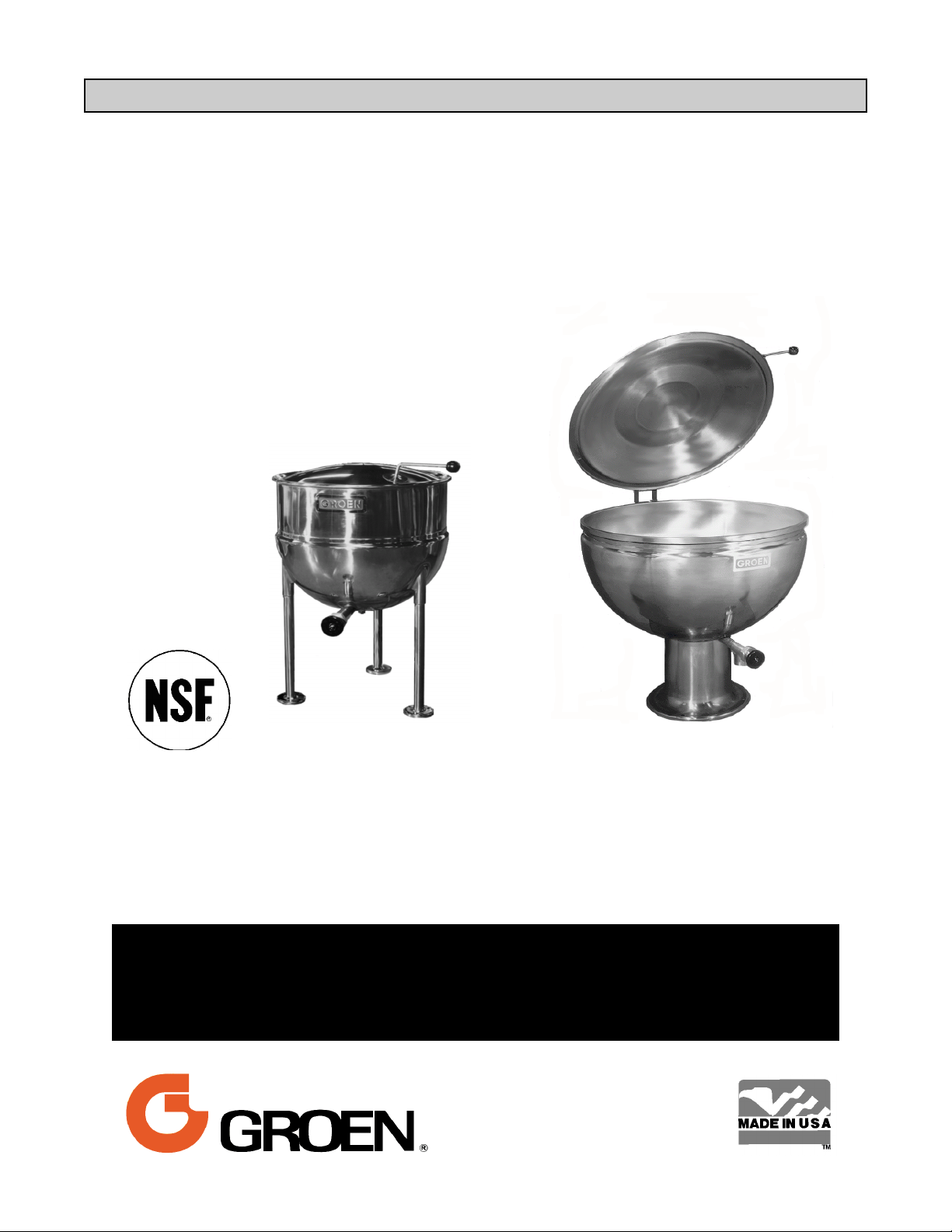
Steam Jacketed Kettles
Stainless Steel
Direct steam heated
Stationary
Model FT
Model GPT
THIS MANUAL MUST BE RETAINED FOR FUTURE REFERENCE.
READ, UNDERSTAND AND FOLLOW THE INSTRUCTIONS AND
WARNINGS CONTAINED IN THIS MANUAL.
WARNING
DO NOT STORE OR USE GASOLINE OR OTHER FLAMMABLE
VAPORS AND LIQUIDS IN THE VICINITY OF THIS OR ANY OTHER
APPLIANCE.
.
Information contained in this document is
known to be current and accurate at the time
of printing/creation. Unified Brands recommends referencing our product line websites,
unifiedbrands.net, for the most updated
product information and specifications.
Page 2

OM-FT
IMPORTANT — READ FIRST — IMPORTANT
CAUTION: BE SURE ALL OPERATORS READ, UNDERSTAND AND FOLLOW THE OPERATING
INSTRUCTIONS, CAUTIONS, AND SAFETY INSTRUCTIONS CONTAINED IN THIS
MANUAL.
WARNING: THIS UNIT IS INTENDED FOR USE IN THE COMMERCIAL HEATING, COOKING AND
HOLDING OF WATER AND FOOD PRODUCTS, PER THE INSTRUCTIONS
CONTAINED IN THIS MANUAL. ANY OTHER USE COULD RESULT IN SERIOUS
PERSONAL INJURY OR DAMAGE TO THE EQUIPMENT AND WILL VOID
WARRANTY.
WARNING: KETTLES MUST BE INSTALLED BY PERSONNEL QUALIFIED TO WORK WITH
PLUMBING. IMPROPER INSTALLATION CAN RESULT IN INJURY TO PERSONNEL
AND/OR DAMAGE TO EQUIPMENT.
WARNING: AVOID ANY EXPOSURE TO ESCAPING STEAM. STEAM CAN CAUSE SEVERE
BURNS.
WARNING: AVOID ALL DIRECT CONTACT WITH HOT EQUIPMENT SURFACES. DIRECT SKIN
CONTACT COULD RESULT IN SEVERE BURNS.
WARNING: AVOID ALL DIRECT CONTACT WITH HOT FOOD OR WATER IN KETTLES. DIRECT
CONTACT COULD RESULT IN SEVERE BURNS.
CAUTION: DO NOT OVER FILL THE KETTLE WHEN COOKING, HOLDING OR CLEANING.
KEEP LIQUIDS A MINIMUM OF 2-3” (5-8 cm) BELOW THE KETTLE BODY RIM TO
ALLOW CLEARANCE FOR STIRRING, BOILING AND SAFE PRODUCT TRANSFER.
WARNING: TAKE SPECIAL CARE TO AVOID CONTACT WITH HOT KETTLE BODY OR HOT
PRODUCT WHEN ADDING INGREDIENTS, STIRRING OR TRANSFERRING
PRODUCT TO ANOTHER CONTAINER.
CAUTION: KEEP FLOORS IN FRONT OF KETTLE WORK AREA CLEAN AND DRY. IF SPILLS
OCCUR, CLEAN IMMEDIATELY, TO AVOID SLIPS OR FALLS.
WARNING: FAILURE TO CHECK SAFETY VALVE OPERATION PERIODICALLY COULD RESULT
IN PERSONAL INJURY AND/OR DAMAGE TO EQUIPMENT.
WARNING: WHEN TESTING, AVOID ANY EXPOSURE TO THE STEAM BLOWING OUT OF THE
SAFETY VALVE. DIRECT CONTACT COULD RESULT IN SEVERE BURNS.
CAUTION: MOST CLEANERS ARE HARMFUL TO THE SKIN, EYES, MUCOUS MEMBRANES
AND CLOTHING. PRECAUTIONS SHOULD BE TAKEN. WEAR RUBBER GLOVES,
GOGGLES OR FACE SHIELD AND PROTECTIVE CLOTHING. CAREFULLY READ
THE WARNINGS AND FOLLOW THE DIRECTIONS ON THE LABEL OF THE
CLEANER TO BE USED.
CAUTION: USE OF ANY REPLACEMENT PARTS OTHER THAN THOSE SUPPLIED BY GROEN
OR THEIR AUTHORIZED DISTRIBUTORS CAN CAUSE OPERATOR INJURY AND
DAMAGE TO THE EQUIPMENT, AND WILL VOID ALL WARRANTIES.
IMPORTANT: SERVICE PERFORMED BY OTHER THAN FACTORY AUTHORIZED PERSONNEL
WILL VOID WARRANTIES.
2
Page 3

OM-FT
Table of Contents
IMPORTANT OPERATOR WARNINGS .................................................. 2
EQUIPMENT DESCRIPTION .......................................................... 4
INSTALLATION ..................................................................... 6
INITIAL START-UP .................................................................. 7
OPERATION ....................................................................... 8
SEQUENCE OF OPERATION .......................................................... 8
CLEANING ......................................................................... 9
MAINTENANCE .................................................................... 10
TROUBLESHOOTING ............................................................... 11
PARTS LISTS ..................................................................... 12
PIPING DIAGRAM .................................................................. 14
REFERENCES ..................................................................... 16
MAINTENANCE LOG ................................................................ 17
WARRANTY ....................................................................... 19
3
Page 4
OM-FT
Equipment Description
1. General
The direct steam heated kettles covered in
this manual are one-piece, welded
constructions of 18.8 type 304 stainless steel,
which are listed by the National Sanitation
Foundation. They have bar rims with a
continuous seal weld on the underside. The
kettles are ASME shop inspected, and
registered with the national board for
operation at pressures up to 25 PSI. They are
finished to 180 emery grit interior, and a bright
semi-deluxe exterior. The table on Page 6
shows standard kettle sizes manufactured for
each model since June, 1986.
Steam from a remote source passes directly
into the jacket. Steam pressure forces
condensate out through the condensate
outlet. The units operate safely and efficiently
at steam pressures from five to 25 PSI. A
safety valve works to release any pressure
above the 25 PSI limit. If required, higher
jacket pressure (PSI) kettles can be provided.
A globe valve is required on the steam inlet,
and a strainer, steam trap and check valve
are needed on the condensate outlet. Each of
these may be ordered as an option (but are
standard on wall-mounted units).
Model PT
The kettles are emptied by tangent draw-offs.
The standard draw-off on current models is a
compression disk type, fabricated from 316
stainless steel with a 2 inch outer diameter
(O.D.). The draw-off has a removable
stainless steel strainer which has ¼ inch
perforations. Options for the draw-off include
a three-inch O.D., a strainer with c inch
perforations, and a solid disk strainer.
2. Models FT, MW/FT and PT are deep kettles
with b jackets. On units with capacities of 40
gallons or less, a one-piece hinged stainless
steel dome cover is furnished. On larger units
the cover is counter-balanced with a Model 51
spring-assisted actuator.
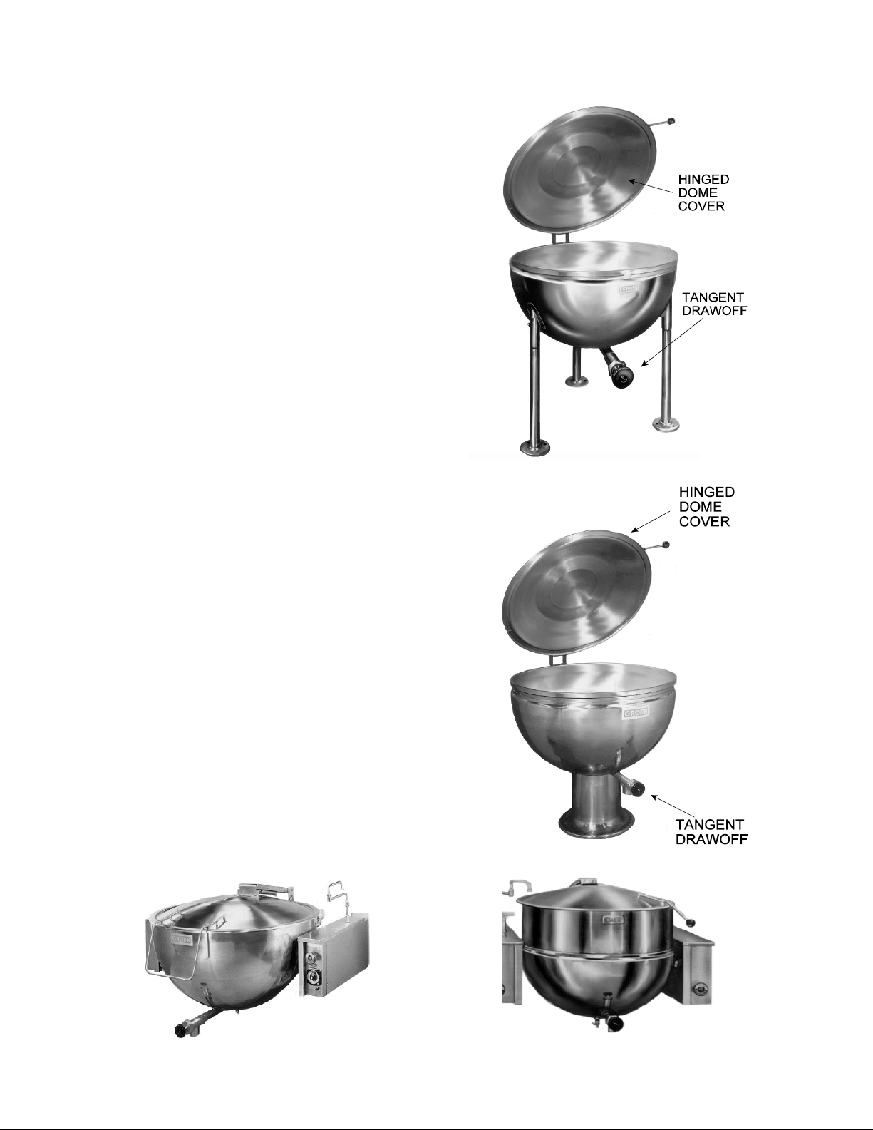
3. Models GT, MW/GT and GPT are fully
jacketed. All sizes are equipped with domed
covers which have counter-balanced
actuators.
Model FT
4
Page 5
4. Models FT and GT stand on stainless steel,
tubular legs, that are continuously welded to
the kettle. The legs are fitted with adjustable
stainless steel floor flanges.
5. Models MW/FT and MW/GT are supported
by a structural steel framework which is
suitable for wall mounting. This framework
hangs on an in-wall carrier which may be
purchased as an option. The frame is
enclosed in a drip-proof, stainless steel
housing. As assembled at the factory, the
support structure includes steam inlet and
condensate outlet piping and valves, a
condensate strainer, trap, and a check
valve. Optional piping and valves are
available for jacket cooling water. Control
valve stems protrude through the front of the
support housing. The top and sides of the
housing may be removed to provide access
for service.
OM-FT
6. Models PT and GPT stand on a stainless
steel pedestal base. The outer surface of
the base is flanged down vertically to permit
proper sealing to the floor or deck. These
units are provided with a standard faucet
bracket.
7. Optional Equipment may include:
a. Plug-type drawoff valves
b. Model FD close-coupled sanitary drain
valves
c. TRI-BC cooking basket system
d. Fill faucet with swing spout
e. Gallon Master water meter
f. Kettle brush kit
g. Cover with No. 51 actuator (40-gallon
kettle)
h. Steam trap assembly
Model GT
Model GPT
MW/GT (Wall Mounted)
MW/FT (Wall Mounted)
5
Page 6
OM-FT
Standard Kettle Capacities, Gallons
Model 20 40 60 80 100 125 150
PT
FT
GT
GPT
MW/FT
THIS UNIT MUST BE INSTALLED BY PERSONNEL QUALIFIED TO WORK WITH PLUMBING.
IMPROPER INSTALLATION CAN CAUSE INJURY TO PERSONNEL AND/OR DAMAGE TO
EQUIPMENT.
Υ Υ Υ Υ Υ
Υ Υ Υ Υ Υ
Υ Υ Υ Υ Υ Υ
Υ Υ Υ Υ Υ Υ
Υ Υ Υ
Installation
WARNING
A. All Models
1. Installation under a ventilation hood is
recommended.
2. If the steam supply pressure is greater than
the maximum working pressure stamped on
the nameplate, you must install a pressure
reducing valve in the steam supply line near
the kettle.
3. Connect the steam supply line to the steam
inlet fitting. To obtain the full heating
capability of the kettle, the steam supply line
must be as large as the steam inlet fitting.
4. The safety valve is preset to relieve jacket
pressure that exceeds its rated limit. Do not
try to adjust the valve setting, and do not
allow the valve outlet or lever to be blocked.
5. Connect the kettle condensate return line to
the boiler return line, or to a drain. A
suitable steam trap, strainer, and check
valve must be installed. (See piping
diagram, Page 14-15).
and the surface, as shown. Fill all cracks
and crevices, and wipe excess away.
C. Wall-Mounted Models
6. Any mechanical change must be approved
by the Groen Food Service Engineering
Department.
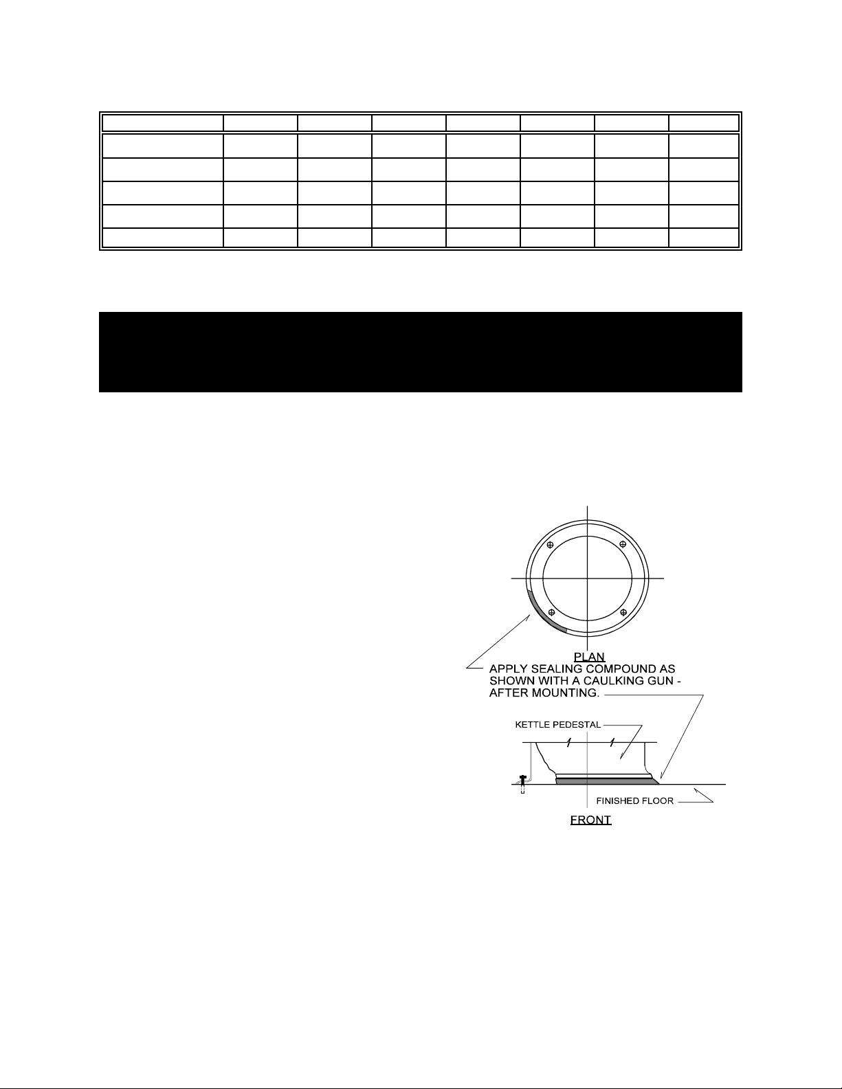
B. Floor-Mounted Models
1. Install the unit on a level surface. Ensure
that there is adequate clearance at the sides
and rear, as required by the specification
drawings. Anchor the pedestal or legs
securely to the floor.
2. Apply a continuous bead of clear silicone
sealant (No. 732 or equivalent) to the
junction between the pedestal or leg flange
For proper sanitation, a continuous seal
is required between pedestals or flanges
and the mounting surface.
1. Install a “chair carrier” in the wall to which
the unit will be attached, following the
instructions pertaining to anchoring and
location.
2. Stub in the steam supply line and
condensate return line so that they will be
aligned with the appropriate fittings when the
unit is mounted.
6
Page 7

OM-FT
4. Apply a continuous bead of clear silicone
3. Mount the unit on the protruding studs of the
chair carrier.
Initial Start-Up
IMPORTANT
BE SURE ALL OPERATORS READ, UNDERSTAND AND FOLLOW THE OPERATING
INSTRUCTIONS, CAUTIONS, AND SAFETY INSTRUCTIONS CONTAINED IN THIS MANUAL.
Now that the kettle has been installed, you
should test it to ensure that it is operating
correctly.
1. Remove all literature and packing
materials from inside and outside of the
unit.
sealant (No. 732 or equivalent) to the
junction between the frame housing and the
wall. Fill all cracks and crevices, and wipe
away the excess.
2. Pour a small amount of water into the
kettle.
3. Open the steam inlet valve.
4. When the water begins to boil, inspect
all of the fittings to ensure that there are
no leaks.
5. Check the safety valve by pulling out on
its chain, (or lifting its lever on older
models) far enough to let steam escape.
Then let it snap back into place to reseat
the valve so that it will not leak.
WARNING
AVOID EXPOSURE TO ESCAPING STEAM,
WHICH CAN CAUSE SEVERE BURNS.
6. Shut down the unit by closing the steam inlet
valve.
7. Operate the drawoff valve to ensure that it
functions across the normal range of
operation.
If the unit functions as described above, it is
ready for use. If the unit does not function as
intended, contact your local Groen Certified
Service Agency.
Test the safety valve each day
7
Page 8

OM-FT
Operation
To heat the kettle, open the condensate return
valve and the steam inlet valve. Adjusting the
inlet valve allows the operator to control the
heating rate. Opening the valve more allows
steam to flow into the jacket faster, and thereby
heats the product faster.
The kettle operates efficiently with steam
pressures from five PSI to the maximum working
pressure for which the kettle was designed. The
maximum allowable pressure (normally 25 PSI
for standard units) is stamped on the kettle
nameplate.
WARNING
AVOID EXPOSURE TO ESCAPING STEAM,
WHICH CAN CAUSE SEVERE BURNS.
Once a day, while there is still steam pressure in
the jacket, bleed off any entrapped air and
double check the operation of the safety valve.
Pull out on its chain, (or lift the lever on older
models) far enough to let steam escape. Then
let it snap back into place to reseat the valve so
that it will not leak.
WARNING
AVOID ALL DIRECT CONTACT WITH HOT
FOOD OR WATER IN THE KETTLE.
DIRECT CONTACT COULD RESULT IN
SEVERE BURNS.
TAKE SPECIAL CARE TO AVOID
CONTACT WITH HOT KETTLE BODY OR
HOT PRODUCT, WHEN ADDING
INGREDIENTS, STIRRING OR
TRANSFERRING PRODUCT TO ANOTHER
CONTAINER.
CAUTION
DO NOT OVERFILL THE KETTLE WHEN
COOKING, HOLDING OR CLEANING. KEEP
LIQUIDS AT LEAST 2-3” (5-8 cm) BELOW
THE KETTLE BODY RIM TO ALLOW
CLEARANCE FOR STIRRING, BOILING
PRODUCT AND SAFE TRANSFER.
Sequence of Operation
The following “action-reaction” outline is provided
to help you understand how the equipment
functions.
When the steam inlet valve is opened, steam
flows into the jacket at a pressure determined by
the boiler system, or by the pressure reducing
valve which serves the kettle. In the jacket
steam releases its heat to the kettle as it
condenses into water. The steam trap allows
condensate (water) to leave the kettle while
holding the steam in.
When the steam supply is shut off, condensation
of the remaining steam produces a vacuum in
the jacket, but the check valve in the condensate
return line keeps water from flowing back into
the jacket.
8
Page 9

Cleaning
OM-FT
1. Suggested Tools:
a. Cleaner, such as Klenzade HC-10 or
HC-32 from ECOLAB, Inc.
b. Long- and short-handled kettle brushes
in good condition.
c. Brush suitable for cleaning the draw-off
port.
d. Sanitizer such as Klenzade XY-12.
c. Film remover such as Klenzade LC-30.
CAUTION
MOST CLEANERS ARE HARMFUL TO THE
SKIN, EYES, MUCOUS MEMBRANES, AND
CLOTHING. PRECAUTIONS SHOULD BE
TAKEN. WEAR RUBBER GLOVES,
GOGGLES OR FACE SHIELD, AND
PROTECTIVE CLOTHING. READ THE
WARNINGS AND FOLLOW THE
DIRECTIONS ON THE LABEL OF THE
CLEANER CAREFULLY.
2. Procedure
a. Clean food-contact surfaces as soon as
possible after use, preferably while the
kettle is still hot. If the unit is in
continuous use, thoroughly clean and
sanitize the interior and exterior at least
once every 12 hours.
f. Disassemble the tangent draw-off valve.
Clean the draw-off pipe and each valve
part with a brush.
CAUTION
DO NOT MIX DIFFERENT KETTLE DRAWOFF ASSEMBLY PARTS WHEN WASHING.
THEY ARE NOT INTERCHANGEABLE
g. Rinse the kettle and draw-off parts
thoroughly with warm water, then drain
completely.
h. As part of the daily cleaning, clean all
external and internal surfaces that may
have been soiled. Remember to check
such areas as the underside of the
cover.
i. To remove burned-on materials, use a
brush, sponge, cloth, plastic or rubber
scraper, or plastic wool with the cleaning
solution. To reduce effort required in
washing, let the detergent solution sit in
the kettle and soak into the residue. Do
not use abrasive materials or metal
tools that might scratch the surface.
Scratches make the surface harder to
clean and provide places for bacteria to
grow.
WARNING
AVOID ANY DIRECT CONTACT WITH HOT
SURFACES. DIRECT SKIN CONTACT
COULD RESULT IN SEVERE BURNS.
b. Scrape and flush out food residues with
lukewarm water. After flushing the kettle,
close the draw-off valve.
c. Prepare a hot solution of the detergent/
cleaning compound as instructed by the
supplier. Set some of this solution
aside to use in cleaning the draw-off
valve and pipe.
d. Clean the unit thoroughly, inside and
outside.
e. Drain the kettle.
j. Do not use steel wool, which may
leave particles in the surface and cause
eventual corrosion and pitting.
Use brushes, sponges or cloth to clean your
kettles
9
Page 10

OM-FT
Don’t scrape with tools, steel wool or other
abrasives.
k. The outside of the unit may be polished
with a stainless steel cleaner such as
“Zepper” from Zep Manufacturing Co.
NOTICE
NEVER LEAVE A CHLORINE SANITIZER IN
CONTACT WITH STAINLESS STEEL
SURFACES LONGER THAN 30 MINUTES.
LONGER CONTACT CAN CAUSE STAINING
AND CORROSION.
m. It is recommended that each piece of
equipment be sanitized just before use.
n. If there is difficulty removing mineral
deposits or a film left by hard water or
food residues, clean the kettle
thoroughly and use a deliming agent,
like Groen Delimer/Descaler (Part
Number 114800) or Lime-Away® from
Ecolab, in accordance with the
manufacturer’s directions. Rinse and
drain the unit thoroughly before further
use.
l. When equipment needs to be sanitized,
use a solution equivalent to one that
supplies 200 parts per million available
chlorine. Obtain advice on sanitizing
agents from your supplier of sanitizing
products. Following the supplier’s
instructions, apply the agent after the
unit has been cleaned and drained.
Drain and thoroughly rinse off the
sanitizer.
o. If cleaning problems persist, contact
your cleaning product representative for
assistance. The supplier has a trained
technical staff with laboratory facilities to
serve you.
Maintenance
NOTICE: Contact Groen or an authorized Groen representative when repairs are required.
Periodic Maintenance
A Maintenance & Service Log is provided at the
back of this manual with the warranty
information. Each time maintenance is
performed on your Groen kettle, enter the date
on which the work was done, what was done,
and who did it. Keep this manual on file and
available for operators to use.
Periodic inspection will minimize equipment
down time and increase the efficiency of
operation. The following points should be
checked:
WHEN TESTING, AVOID ANY EXPOSURE
TO THE STEAM BLOWING OUT OF THE
SAFETY VALVE. DIRECT CONTACT
COULD RESULT IN SEVERE BURNS.
WARNING
1. Once a day, with pressure in the jacket,
check the operation of the pressure
relief safety valve. Lift
the lever of the safety
valve until steam is
released.
Check safety valve once each day.
Then release the lever and let the valve
snap shut. If the lever does not activate,
or there is no evidence of discharge, or
10
Page 11

OM-FT
the valve leaks, immediately discontinue
use of the kettle and contact a qualified
Groen service representative.
2. At least once every 90 days, inspect
fittings and valves for signs of damage
or wear.
NOTE: Service performed by other than factoryauthorized personnel will void all warranties.
Troubleshooting
Your Groen kettle will operate smoothly and efficiently if properly maintained. However, the following is a
list of checks to make in the event of a problem. If the actions suggested do not solve the problem,
call your qualified Groen Service Representative. For the phone number of the nearest agency, call
your area Groen representative or the Groen Parts and Service Department. If an item on the list is
followed by Ψ, the work should be done by a qualified service representative.
WARNING
USE OF ANY REPLACEMENT PARTS OTHER THAN THOSE SUPPLIED BY GROEN OR THEIR
AUTHORIZED DISTRIBUTORS CAN CAUSE INJURY TO THE OPERATOR AND DAMAGE TO THE
EQUIPMENT AND WILL VOID ALL WARRANTIES.
SYMPTOM WHO WHAT TO CHECK
Ψindicates items which must be performed by an authorized technician.
Kettle will not heat. User a. That the steam inlet valve is open.
b. That the steam supply line is turned on.
c. That the condensate return valve is open.
d. That the boiler is operating properly. Steam should be
supplied at a pressure greater than five PSI.
Auth Service
Rep Only
Safety valve leaks a
small amount of steam.
Safety valve leaks a
large amount of steam.
Pipe fitting leaks User a. Is the fitting tight?
User a. For contamination that prevents seating the valve. With
Auth Service
Rep Only
Auth Service
Rep Only
Auth Service
Rep Only
e. Steam supply line for blockage.Ψ
f. Condensate return line for blockage.Ψ
g. Steam trap operation.Ψ
substantial pressure in the jacket, lift the valve lever briefly
all the way up, to blow the valve clean then let it snap back
down to seat the valve.
b. Safety valve for defects. Defective valve MUST be replaced
with a valve rated at the same pressures.Ψ
a. Steam supply pressure.Ψ
b. Safety valve for defects. Defective valve MUST be replaced
with a valve rated at the same pressures.Ψ
b. If tightening the packing gland does not stop the leak,
replace the packing.Ψ
11
Page 12

OM-FT
Parts List
To order parts, contact your authorized Groen Service Agency. Supply the model designation, part
description, quantity, and where applicable, voltage and phase.
Models FT & PT
10 to 40 Gallons Inclusive
Key Description Part No. Key Description Part No.
1 ¼"-20 N.C. Cap Nut 005471 16 Stem for 1-1/2" Valve 009027
2 Spacer 012733 Stem for 2" Valve 009048
3 Handle (Covers w/Actuator)* 047712 Stem for 3" Valve 001908
Cover Actuator 120521 17 Bonnet for 1½" Valve 009024
Cover Handle 120915 Bonnet for 2" Valve 009047
U-Handle 010245 Bonnet for 3" Valve 003925
4 Knob (Friction) 012691 18 O-Ring for 1½" & 2" Valves 009034
5 Spring (28" & 30" Covers) 012303 19 Hex Nut 1½" Valve 008911
6 Spring (32" & 36" Covers) 012413 Hex Nut 2" Valve 009354
7 Spring (38" & 42" Covers) 012533 Hex Nut 3" Valve 003927
8 Spring (44" & 48" Covers) 012565 20 Handle for 1½" & 2" Valves 009029
9 Spring (50" Covers) 012566 Handle for 3" Valve 012209
10 ½"-20 N.F. x 1" Lg Hex Hd Capscr. 002212 21 Wing Nut for 1½" & 2" Valves 009028
11 ½" Brass Washer 002213 22 Removable Strainer 9" Dia ¼" holes 009007
12 ½"-20 N.F. Jam Nut 010668 23 Removable Strainer 9" Dia c ” holes 009040
13 ¾" I.P.S. Street Elbow 011004 24 Removable Strainer 9" Dia no holes 009057
14 #25-¾" Safety Valve 011004 Strainer, ¼” Per. 009986
15 1½" Draw-Off Valve Complete 009000 Strainer, Vertical 009987
1½” Draw-Off Tube 010632 25 R.H. Cover Hinge 002292
2" Draw-Off Valve Complete 009046 26 L.H. Cover Hinge 002293
2" Draw-Off Tube 038418 27 R.H. Hinge Half 012877
3" Draw-Off Valve Complete 012262 28 L.H. Hinge Half 012878
12
Page 13

OM-FT
Model GPT 20
Models FT and PT 60 Gallons and Larger
Models GT and GPT 25 Gallons and Larger
13
Page 14

OM-FT
Piping Diagram*
(Bucket Type Steam Trap Assembly)
ITEM NO. DESCRIPTION
1 Bushing
2 Close Nipple
3 Female Union
4 Street Elbow
5 Bucket Steam Trap
6 Swing Check Valve
7 Gate Valve
8 Globe Valve
9 Close Nipple
19 Female Union
INLET SIZE OUTLET SIZE USED ON
1/2" I.P.S 1/2" I.P.S
3/4" I.P.S 1/2" I.P.S
1" I.P.S 3/4" I.P.S
FT - 10, 20 & 30
PT - 10, 20 & 30
FT - 40 & 60
PT - 40 & 60
GT - 20 & 25
GPT 20 & 25
FT - 80 & 100
PT - 80 & 100
GT - 40, 50, 60,
80, 100
GPT 40, 50, 60,
80, 100
*All of the fittings illustrated are required for
proper and safer installation and operation, and
are NOT PROVIDED as standard with the unit.
Steam trap assemblies are available from
Groen and can be purchased in two versions.
1. COMPLETELY PIPED — Complete,
preassembled, with nipples and fittings, as
shown in the diagram
2. LOOSE — Unassembled, without nipples and
fittings, but includes steam trap, check valve,
globe valve and gate valve.
NOTE - All steam trap assemblies are shipped
in a separate container and are not mounted on
the kettle to prevent damage during shipment.
A steam pressure reducing valve (PRV) is
available at extra cost for installation when
steam pressure exceeds the kettle’s maximum
working pressure. It is to be mounted on the
steam inlet side, just before the steam valve
(globe valve), as close to the kettle as possible.
PART NUMBER
STANDARD FINISH ROUGH CHR. PLT. POL. CHR. PLT.
025373 044884 062999
025374 040618 040624
025923 065788 054149
14
Page 15

Piping Diagram*
(Thermostatic Type Steam Trap Assembly)
OM-FT
ITEM NO. DESCRIPTION
1 Bushing
2 Close Nipple
3 Female Union
4 Street Elbow
5 Thermostatic Steam Trap
6 Swing Check Valve
7 Gate Valve
8 Close Nipple
9 Female Union
10 Globe Valve
INLET SIZE OUTLET SIZE USED ON
1/2" I.P.S 1/2" I.P.S
3/4" I.P.S 1/2" I.P.S
1" I.P.S 3/4" I.P.S
FT - 10, 20 & 30
PT - 10, 20 & 30
FT - 40 & 60
PT - 40 & 60
GT - 20 & 25
GPT 20 & 25
FT - 80 & 100
PT - 80 & 100
GT - 40, 50, 60,
80, 100
GPT 40, 50, 60,
80, 100
*All of the fittings illustrated are required for
proper and safer installation and operation, and
are NOT PROVIDED as standard with the unit.
Steam trap assemblies are available from
Groen and can be purchased in two versions.
1. COMPLETELY PIPED — Complete,
preassembled, with nipples and fittings, as
shown in the diagram
2. LOOSE — Unassembled, without nipples and
fittings, but includes steam trap, check valve,
globe valve and gate valve.
NOTE - All steam trap assemblies are shipped
in a separate container and are not mounted on
the kettle to prevent damage during shipment.
A steam pressure reducing valve (PRV) is
available at extra cost for installation when
steam pressure exceeds the kettle’s maximum
working pressure. It is to be mounted on the
steam inlet side, just before the steam valve
(globe valve), as close to the kettle as possible.
PART NUMBER
STANDARD FINISH ROUGH CHR. PLT. POL. CHR. PLT.
045171 059473 090530
041065 050948 040685
045171 048763 040686
15
Page 16

OM-FT
References
KLENZADE SALES CENTER
ECOLAB. Inc.
370 Wabasha
St. Paul, Minnesota 55102
800/352-5326 or 612/293-2233
NATIONAL SANITATION FOUNDATION
3475 Plymouth Rd.
Ann Arbor, Michigan 48106
ZEP MANUFACTURING CO.
1310-T Seaboard Industrial Blvd.
Atlanta, Georgia 30318
16
Page 17

Service Log
Model No. Purchased From
Serial No. Location
Date Purchased Date Installed
Purchase Order No. For Service Call
Date Maintenance Performed Performed by
OM-FT
17
Page 18

OM-FT
NOTES
18
Page 19

OM-FT
Limited Warranty
To Commercial Purchasers *
(Domestic U.S., Hawaii &
Canadian Sales Only)
Groen Foodservice Equipment ("Groen Equipment") has been skillfully manufactured, carefully inspected
and packaged to meet rigid standards of excellence. Groen warrants its Equipment to be free from defects
in material and workmanship for (12) twelve months with the following conditions and subject to the
following limitations.
I. This parts and labor warranty is limited to Groen Equipment sold to the original commercial
purchaser/users (but not original equipment manufacturers), at its original place of installation in
the continental United States, Hawaii and Canada.
II. Damage during shipment is to be reported to the carrier, is not covered under this warranty, and is
the sole responsibility of purchaser/user.
III. Groen, or an authorized service representative, will repair or replace, at Groen's sole election, any
Groen Equipment, including but not limited to, drawoff valves, safety valves, gas and electric
components, found to be defective during the warranty period. As to warranty service in the
territory described above, Groen will absorb labor and portal to portal transportation costs (time &
mileage) for the first twelve (12) months from date of installation or fifteen (15) months from date
of shipment from Groen.
IV. This warranty does not cover boiler maintenance, calibration, periodic adjustments as specified in
operating instructions or manuals, and consumable parts such as scraper blades, gaskets,
packing, etc., or labor costs incurred for removal of adjacent equipment or objects to gain access
to Groen Equipment. This warranty does not cover defects caused by improper installation,
abuse, careless operation, or improper maintenance of equipment. This warranty does not cover
damage caused by poor water quality or improper boiler maintenance.
V. THIS WARRANTY IS EXCLUSIVE AND IS IN LIEU OF ALL OTHER WARRANTIES,
EXPRESSED OR IMPLIED, INCLUDING ANY IMPLIED WARRANTY OF MERCHANTABILITY
OR FITNESS FOR A PARTICULAR PURPOSE, EACH OF WHICH IS HEREBY EXPRESSLY
DISCLAIMED. THE REMEDIES DESCRIBED ABOVE ARE EXCLUSIVE AND IN NO EVENT
SHALL GROEN BE LIABLE FOR SPECIAL, CONSEQUENTIAL OR INCIDENTAL DAMAGES
FOR THE BREACH OR DELAY IN PERFORMANCE OF THIS WARRANTY.
VI. Groen Equipment is for commercial use only. If sold as a component of another (O.E.M.)
manufacturer's equipment, or if used as a consumer product, such Equipment is sold AS IS and
without any warranty.
* (Covers All Foodservice Equipment Ordered After October 1, 1995)
19
Page 20

1055 Mendell Davis Drive
Jackson, MS 39272
Telephone 601 372-3903
FAX 601 373-9587
OM-FT (Revised 2/98)
Part Number 121008
 Loading...