

Groen DH-INA-2-100 Service Manual

? IMPORTANT INFORMATION ? KEEP FOR OPERATOR ? IMPORTANT INFORMATION?
OPERATOR MANUAL OM-DH/INA/2-100
Part Number 121018 DOMESTIC
Model: DH/INA/2-100
Steam Jacketed Kettle
Self-contained
Gas heated
Floor Mounted
Tilting
THIS MANUAL MUST BE RETAINED FOR FUTURE REFERENCE. READ, UNDERSTAND
AND FOLLOW THE INSTRUCTIONS AND WARNINGS CONTAINED IN THIS MANUAL.
FOR YOUR SAFETY
DO NOT STORE OR USE GASOLINE OR OTHER FLAMMABLE VAPORS
AND LIQUIDS IN THE VICINITY OF THIS OR ANY OTHER APPLIANCE.
POST IN A PROMINENT LOCATION
INSTRUCTIONS TO BE FOLLOWED IN THE EVENT USER SMELLS GAS.
THIS INFORMATION SHALL BE OBTAINED BY CONSULTING YOUR
LOCAL GAS SUPPLIER. AS A MINIMUM, TURN OFF THE GAS AND CALL
YOUR GAS COMPANY AND YOUR AUTHORIZED SERVICE AGENT.
EVACUATE ALL PERSONNEL FROM THE AREA.
WARNING: IMPROPER INSTALLATION, ADJUSTMENT, ALTERATION,
SERVICE OR MAINTENANCE CAN CAUSE PROPERTY DAMAGE, INJURY
OR DEATH. READ THE INSTALLATION, OPERATING AND
MAINTENANCE INSTRUCTIONS THOROUGHLY BEFORE INSTALLING
OR SERVICING THIS EQUIPMENT.
Information contained in this document is
known to be current and accurate at the time
of printing/creation. Unified Brands recommends referencing our product line websites,
unifiedbrands.net, for the most updated
product information and specifications.

OM-DH/INA/2-100
IMPORTANT — READ FIRST — IMPORTANT
WARNING: FAILURE TO DISCONNECT POWER BEFORE SERVICING COULD RESULT IN
ELECTROCUTION AND DEATH.
WARNING: IMPROPER INSTALLATION, ADJUSTMENT, ALTERATION, SERVICE OR MAINTENANCE
CAN CAUSE PROPERTY DAMAGE, INJURY OR DEATH. READ THE INSTALLATION,
OPERATING AND MAINTENANCE INSTRUCTIONS THOROUGHLY BEFORE INSTALLING OR
SERVICING THIS EQUIPMENT.
WARNING: DO NOT PLACE HANDS, TOOLS OR HOSES IN KETTLE WHILE AGITATOR IS MOVING.
AGITATOR CAN BE JOGGED WHILE KETTLE IS TILTED.
WARNING: THE UNIT MUST BE INSTALLED BY PERSONNEL QUALIFIED TO WORK WITH
ELECTRICITY AND PLUMBING. UNIT MUST BE INSTALLED IN ACCORDANCE WITH ALL
APPLICABLE CODES.
WARNING: DO NOT ATTACH THE UNIT TO A TYPE “B” VENT. IT COULD CAUSE FIRE OR PROPERTY
DAMAGE.
WARNING: DO NOT CONNECT ANY PIPING TO THE SAFETY VALVE. IT MUST BE FREE TO VENT
STEAM AS NEEDED. TO AVOID BURNS FROM THE VENTED STEAM THE VALVE
DISCHARGE SHOULD POINT DOWNWARD.
DANGER: ELECTRICALLY GROUND THE UNIT AT THE TERMINAL PROVIDED. FAILURE TO GROUND
THE UNIT COULD RESULT IN ELECTROCUTION AND DEATH.
CAUTION: BE SURE ALL OPERATORS READ, UNDERSTAND AND FOLLOW THE OPERATING
INSTRUCTIONS, CAUTIONS AND SAFETY INSTRUCTIONS CONTAINED IN THIS MANUAL.
CAUTION: DO NOT OVERFILL THE KETTLE WHEN COOKING, HOLDING OR CLEANING. KEEP
LIQUIDS A MINIMUM OF 2-3" (5-8 CM) BELOW THE KETTLE BODY RIM TO ALLOW
CLEARANCE FOR STIRRING, BOILING AND SAFE TRANSFER OF PRODUCT.
CAUTION: KEEP FLOORS IN FRONT OF KETTLE WORK AREA CLEAN AND DRY. IF SPILLS OCCUR,
CLEAN IMMEDIATELY TO AVOID SLIPS OR FALLS.
WARNING: KEEP WATER AND SOLUTIONS OUT OF CONTROLS AND BURNERS. NEVER SPRAY OR
HOSE DOWN THE CONTROL CONSOLE, ELECTRICAL CONNECTIONS, ETC.
CAUTION: MOST CLEANERS ARE HARMFUL TO THE SKIN, EYES, MUCOUS MEMBRANES AND
CLOTHING. TAKE PRECAUTIONS: WEAR RUBBER GLOVES, GOGGLES OR FACE SHIELD
AND PROTECTIVE CLOTHING. CAREFULLY READ WARNINGS AND FOLLOW
DIRECTIONS ON CLEANER LABELS .
NOTICE: NEVER LEAVE A SANITIZER IN CONTACT WITH STAINLESS STEEL SURFACES LONGER
THAN 10 MINUTES. LONGER CONTACT CAN CAUSE CORROSION.
WARNING: FAILURE TO PERIODICALLY CHECK SAFETY VALVE OPERATION COULD RESULT IN
PERSONAL INJURY AND/OR DAMAGE TO EQUIPMENT.
WARNING: WHEN TESTING, AVOID EXPOSURE TO THE STEAM BLOWING OUT OF THE SAFETY
VALVE. DIRECT CONTACT COULD RESULT IN SEVERE BURNS.
WARNING: TO AVOID INJURY, READ AND FOLLOW ALL PRECAUTIONS STATED ON THE LABEL OF
THE WATER TREATMENT COMPOUND.
WARNING: BEFORE REPLACING ANY PARTS, DISCONNECT THE UNIT FROM THE ELECTRIC POWER
SUPPLY AND CLOSE THE MAIN GAS VALVE. ALLOW FIVE MINUTES FOR GAS TO VENT.
CAUTION: USE OF ANY REPLACEMENT PARTS OTHER THAN THOSE SUPPLIED BY GROEN OR
AUTHORIZED DISTRIBUTORS CAN CAUSE INJURY TO THE OPERATOR AND DAMAGE TO
THE EQUIPMENT AND WILL VOID ALL WARRANTIES.
Important: Service Performed by Other than Factory Authorized Personnel Will Void All Warranties.
WARNING: KEEP AREA AROUND KETTLE FREE AND CLEAR OF ALL COMBUSTIBLE MATERIALS.
FAILURE TO DO SO COULD RESULT IN FIRE OR PROPERTY DAMAGE.
WARNING: OPENING BOTTOM DROP VALVE EMPTIES KETTLE CONTENTS. CONTENTS MAY BE
HOT.
CAUTION: HEATING AN EMPTY KETTLE MAY CAUSE THE RELEASE OF STEAM FROM THE SAFETY
VALVE.
2

OM-DH/INA/2-100
Table of Contents
INSTALLER AND OPERATOR WARNINGS .....................................2
EQUIPMENT DESCRIPTION .................................................4
INSPECTION & UNPACKING ................................................ 5
INSTALLATION & START-UP ................................................ 7
OPERATION .............................................................9
CLEANING ..............................................................12
PREVENTIVE MAINTENANCE ..............................................15
SEQUENCE OF OPERATION ............................................... 16
MAINTENANCE .........................................................17
TROUBLESHOOTING (OPERATOR) .........................................18
PARTS LISTS & SCHEMATICS ..............................................20
REFERENCES ...........................................................37
SERVICE LOG ...........................................................38
WARRANTY .............................................................39
3

OM-DH/INA/2-100
Equipment Description
Groen Model DH/INA/2-100 is a stainless steel,
steam jacketed, floor mounted, tilting kettle with a
self-contained, gas heated steam source. The
Model DH/INA/2-100 is equipped with the INA/2
style inclined agitator/mixer. The kettle body is
welded into one piece and furnished with a
reinforced bar rim and welded “butterfly” pouring lip.
The interior of the kettle is polished to a 180 emery
grit finish and the exterior given a uniform Number 4
finish.
The unit is ASME shop-inspected and is registered
with the National Board for working pressures up to
50 PSI. Kettle supports mount directly to the floor by
use of lag bolts. A power tilt feature is standard.
Options available include: Air-operated bottom outlet
valve, 1½, two or three inch manual ball valve,
“Gallon Master” metering system, product outlet
strainer, and Honeywell DPR 100C Recorder.
The self-contained steam source is heated by either
propane or natural gas. The ignition system is spark
or standing pilot. The kettle is charged at the factory
with chemically pure water containing corrosion
inhibitors. The steam source provides kettle
temperatures of 150 to approximately 280 o F.
Controls for the unit include a thermostat, pressure
gauge, water level glass, safety valve, pressure limit
control, low water cutoff, gas regulator valve, and a
printed circuit board that monitors product
temperature. The gas supply shuts down
automatically when the kettle is tilted. The agitator
operates only in partial rotation mode when the
kettle is tilted.
The unit must be specified for use with natural or
propane gas. Service connections are required for
gas, electric, air (if the air-operated valve is
specified), water (if Gallon Master metering is
specified).
4
OM-DH/INA/2-100
KETTLE CHARACTERISTICS
Firing Rate, BTU / Hour
Model Ignition Natural Gas Propane Gas
DH-INA/2-100 Electronic 360,000 360,000
Dimensions
Kettle Capacity Kettle Diameter Overall Width
100 Gal (378.5 L) 34" (86 cm) 64¼” (163 cm) 54" (137 cm) 54¼” (138 cm)
Overall Front-to-
Back
Rim Height
Inspection & Unpacking
WARNING
THIS UNIT MUST BE INSTALLED BY PERSONNEL WHO ARE QUALIFIED TO WORK WITH ELECTRICITY
AND PLUMBING. IMPROPER INSTALLATION CAN CAUSE INJURY TO PERSONNEL AND/OR DAMAGE
TO THE EQUIPMENT. THE UNIT MUST BE INSTALLED IN ACCORDANCE WITH APPLICABLE CODES.
The unit is delivered completely assembled, on a heavy
skid surrounded by a wooden crate.. Immediately upon
receipt, inspect the unit for damage. Report any shipping
damage or an incorrect shipment to the delivery agent.
Write down the model number, serial number, and
installation date of your unit, and keep this information
for future reference. Space for these entries is provided
at the top of the Service Log provided at the rear of this
manual. The unit is anchored to two metal shipping
channels (braces) which may be discarded after
installation. Carefully unbolt one side of shipping
channel. Position the kettle and remove second
shipping channel.
WARNING
SHIPPING CHANNELS (BRACES) ARE VERY
HEAVY. USE PROPER LIFTING AND HANDLING
EQUIPMENT FOR MOVEMENT
CAUTION
WATCH OUT FOR NAILS AND SPLINTERS
WHILE DISMANTLING THE SHIPPING CRATE.
The unit is delivered crated and bolted to a heavy
skid.
Two heavy shipping channels (braces) anchor
the unit for shipment.
5
OM-DH/INA/2-100
CAUTION
UNIT HAS AN APPROXIMATE SHIPPING WEIGHT OF
1750 LBS. (795 KG.). FOR SAFE HANDLING,
INSTALLER SHOULD OBTAIN PROFESSIONAL
RIGGING HELP AS NEEDED AND USE MATERIAL
HANDLING EQUIPMENT (SUCH AS A FORKLIFT,
OVERHEAD HOIST, OR PALLET JACKS) TO
REMOVE THE UNIT FROM THE SKID AND MOVE IT
TO ITS PLACE OF INSTALLATION.
When installation is to begin, unbolt the unit from the
skid, and lift the unit straight up and off the skid.
UTILITY REQUIREMENTS
1. Electrical Supply Connection-3 Phase Operation
Only
a. The panel must be removed to gain access to the
electrical supply connection. Open the wiring and
control panel by unscrewing the eight screws
which hold it in place. Grasp the panel by the
base at the bottom edge. While lifting the panel,
swing its bottom toward you. Set the panel aside.
b. Supply Voltage: The unit must operate at the
rated nameplate voltage, plus or minus 10
percent.
c. Wiring Information: Refer to the electrical
schematic for wiring information. A copy of the
schematic is found inside the control panel and at
the rear of this manual.
d. Terminal Block: The terminal block for incoming
power is located at the back of the control
compartment. The ground terminal is located next
to the terminal block. The unit must have a
separate ground wire for safe operation.
Maximum Voltage Three Phase Current, Per Line
208 7 AMP
240 7 AMP
480 3.5 AMP
2. Water Connection(s)
Install a check valve in the incoming cold water
line, if required by local plumbing codes. Water
pressure in the line should be between 30 and 60
PSIG (210 and 420 kPa).
A ¾ NPT connector is needed to attach the water
supply to the water inlet valve. The minimum
recommended water feed line diameter is ½ inch
(13mm).
Do not allow the connection to leak, no matter
how slowly. THE INSTALLER MUST PROVIDE
THE CHECK VALVE (ANTI-SYPHON DEVICE)
IF REQUIRED BY LOCAL CODES.
3. Air Connection.
Connect d NPT air line to the air connector.
4. Gas Connection
Connect 1 NPT gas line to the gas inlet valve on
the rear of the left stanchion. Be sure that the
gas supply meets the following criteria:
Natural Gas Propane
Minimum 7" W.C. 11" W.C.
Maximum 10" W.C. 14" W.C.
e. High Voltage safety
WARNING
TO AVOID DAMAGE OR INJURY, FOLLOW THE
ELECTRICAL SCHEMATIC EXACTLY WHEN
CONNECTING THE UNIT.
f. Branch Circuit Protection: Each conductor must
have over-current protection. Refer to the label
on the back of the unit for the proper wire type
and size. Connections to the unit must be
watertight.
We strongly recommend that the DH/INA/2-100
Kettle have its own branch circuit protection.
Current and power demands for the different
voltage units are as follows:
Gas, Water and Air Connections are on the
back of the left stanchion
6
OM-DH/INA/2-100
WARNING
THIS UNIT IS FOR COMMERCIAL USE. NEVER USE HOME OR RESIDENTIAL GRADE GAS CONNECTIONS.
THEY DO NOT MEET GAS CODES AND COULD BE HAZARDOUS.
Installation and Initial Start-Up
A. Installation
The unit should be installed in a well-ventilated room on
non-combustible flooring. Anything which might
obstruct or restrict the flow of air for combustion and
ventilation must be removed. The area directly around
the appliance must be free of combustible materials.
1. Installation requires connection with air, gas, water
and electric services. See items 8 to 14 for details.
2. To protect the unit from damage, leave it on the
shipping pallet until installation. When ready to start
installation, disassemble the shipping crate, unbolt the
stanchions, disconnect the shipping channels
(braces) and raise the unit straight up off the skid. Do
WARNING
DO NOT ATTACH THE UNIT TO A TYPE "B"
VENT. FAILURE COULD RESULT IN FIRE OR
PROPERTY DAMAGE.
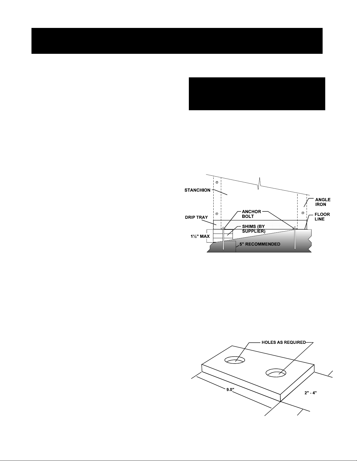
5. Level the unit as follows.
The stanchions are each supplied with a drip tray
in which the angle frame is placed. Steel
leveling shims (not included, supplied by
installer) are placed between the drip tray and
frame so that the drip tray will be flush with the
floor, as shown.
Lifting the kettle at the heat exchanger could damage
the unit.
not lift the kettle at the heat exchanger.
3. Install the unit with at least 22 inches clearance
from the back walls. Also leave enough room for
easy cleaning, maintenance, and service.
4. Do not alter the kettle in any way. Any mechanical,
electrical, or gas change must be approved by the
Groen Food Service Engineering Department.
Start with the right stanchion and level it as
shown in the sketch. Once the right stanchion is
levelled and properly anchored front to rear, level
the left stanchion front to rear and side to side.
Level the entire unit side to side by placing a four
foot carpenter’s level on the kettle rim. Once the
rim is level from side to side, rotate the level to
check front to back. Shim the left stanchion in
the same manner as the right, and anchor the
equipment firmly to the floor through the shims.
Recommended shim size is shown below.
7

OM-DH/INA/2-100
6. Make sure the jacket water level is correct by
confirming that it is between the marks on the gauge
glass. If the water level is low, follow the instructions
under "Jacket Filling" in the "Maintenance" Section of
this manual.
WARNING
DO NOT CONNECT ANY PIPING TO THE POP
SAFETY VALVE. IT MUST BE FREE TO VENT
STEAM AS NEEDED. THE ELBOW SHOULD
POINT DOWN TOWARD FLOOR. IMPROPER
INSTALLATION WILL VOID WARRANTY
7. To protect personnel from steam coming from the
safety valve, the open end of the elbow at the outlet
must be directed downward. If it is not, turn the
elbow to the correct position.
Requirements Section, Page 6. Use ½ inch
waterproof conduit and waterproof connections.
Observe local Codes and/or The National
Electrical Code in accordance with ANSI/NFPA 70
- latest edition. AN ELECTRICAL GROUND IS
REQUIRED. The electrical schematic is located on
the inside of the service panel. In Canada,
provide electrical service in accordance with the
Canadian Electrical code, CSA C22.1 Part 1
and/or local codes.
10. The internal gas lines of the unit were cleaned and
closed with a gas cock before the unit was shipped
from the factory. Ensure that external gas lines
are free of lint, dirt, metal chips, sealant, grease,
oil or other contaminants, before you connect the
line to the kettle.
11. Connect the kettle gas cock to the gas service
main using a 1" NPT gas connection.
12. Installation must conform with local codes, or in
the absence of local codes, with the National Fuel
Gas Code, ANSI Z 223.1-1988 (or latest edition).
The unit should be installed in an well-ventilated
room with a provision for adequate air supply. The
best ventilation will use a vent hood and exhaust
fan with no direct connection between the vent
duct and the unit flue.
8. I nst
all a check valve in the incoming cold water line, if
required by local plumbing codes, as described in
Paragraph 2, page 6
DANGER
ELECTRICALLY GROUND THE UNIT AT THE
TERMINAL PROVIDED. FAILURE TO GROUND
UNIT COULD CAUSE ELECTROCUTION AND
DEATH.
9. Provide electrical service per Paragraph 1, Electrical
Supply Connecton in the Inspection and Unpacking,
Do NOT obstruct the flue or vent duct after
installation. In Canada, the installation must
conform with the CAN/CGA B149 Installation
Codes for Gas Burning Appliances and
Equipment and/or local codes.
13. Adequate space for proper service and operation
is required. Do NOT block any air intake spacings
to the combustion chamber or obstruct the air flow
by piling or stacking anything near the kettle.
14. After the kettle has been connected to the gas
supply, all gas line joints must be checked for
leaks. DO NOT USE A FLAME TO CHECK FOR
LEAKS. A thick soap solution or other suitable
leak detector should be used.
15. The appliance and its individual shutoff valve must
be disconnected from the gas supply piping
system during any pressure testing of that system
at test pressures in excess of ½ PSIG (3.48 kPa).
The appliance must be isolated from the gas
supply piping system by closing its individual
manual shutoff valve during any testing of the gas
system at pressures equal to or less than ½
PSIG (3.48 kPa).
16. Connect the kettle compressed air supply to a d”
NPT air line
8

17. Check the following to confirm that your kettle has
been installed properly:
’ Enough room between the kettle and nearby
objects for cleaning and service.
OM-DH/INA/2-100
B. Initial Start-Up
After the kettle has been installed, the installer should
test to ensure that the unit is operating correctly.
’ Minimum clearance of 24 inches from sides and
24 from back.
’ Unit vented to an exhaust hood.
’ Kettle level.
’ Correct amount of water in the jacket.
’ Safety valve outlet pointed down.
’ Connected with a waterproof electric power cable
in accordance with Paragraph 1 Electrical Supply
Connecton (above) and local electrical codes.
’ Gas lines cleaned before connection.
’ Gas connected with 1 NPT or larger.
’ Gas line joints checked for leaks.
’ No obstruction to air supply or venting.
’ Gas lines (1 NPT) connected to supply.
’ Water supply connection (¾") completed.
1. Remove all literature and packing materials from
the inside and outside of the unit. Clean out any
material that might clog or damage the product
outlet.
2. Put water into the kettle until the water is about 12
inches deep. Test operation of the product outlet
ball valve by opening it all the way then closing it
before all the water runs out.
3. Make sure the supplies of gas and electric power
are on.
4. Following "Start Kettle Heating" instructions in the
"Operating Instructions" section of this manual,
begin heating the water at the highest thermostat
setting. The pilot lamp should come on as soon as
you pull out the emergency stop and turn on
power. Heating should continue until the water
boils.
5. To turn off the unit, follow “To Stop Kettle Heating”
in “Operating Instructions,” below.
If the kettle functions as described, it is ready for use.
If the unit does not operate as designed, contact an
authorized Groen Service agent.
Operation
ANY POTENTIAL USER OF THE EQUIPMENT MUST BE TRAINED IN SAFE AND CORRECT OPERATING
PROCEDURES
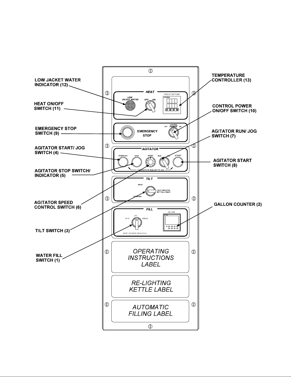
A. Controls
Refer to the drawing on the following page for
identification and function of kettle controls. Numbers in
parentheses in the operating instructions below
correspond to these controls.
B. Operating Instructions
WARNING
KEEP AREA AROUND KETTLE FREE AND CLEAR OF
ALL COMBUSTIBLE MATERIALS
CAUTION
HEATING AN EMPTY KETTLE MAY CAUSE THE
RELEASE OF STEAM FROM THE SAFETY VALVE.
WARNING
1. To Start Kettle
a. CHECK THE WATER LEVEL IN THE
JACKET EVERY DAY. The level must be
between the lines on the glass. If the level
is low, see “Jacket Filling” in the “Preventive
Maintenance” section of this manual.
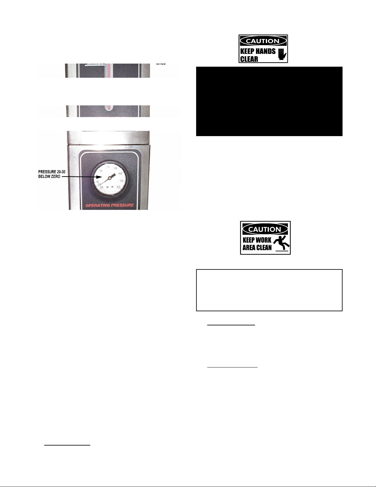
b. With the kettle cold, check the pressure
gauge. If it does not show 20 or more
inches of vacuum (a reading of 20 to 30
below 0), see “Jacket Vacuum” in the
“Preventive Maintenance” section of this
manual.
9
OM-DH/INA/2-100
Right Stanchion Control Panel
10
Check water level and vacuum daily.
OM-DH/INA/2-100
WARNING
DO NOT PLACE HANDS, TOOLS, OR HOSES IN
KETTLE WHILE AGITATOR IS MOVING.
AGITATOR CAN BE JOGGED WHILE KETTLE IS
TILTED.
ENSURE AGITATOR AREA IS CLEAR BEFORE
RUNNING OR JOGGING THE AGITATOR.
SERIOUS INJURY CAN RESULT.
a. Ensure kettle is upright (tilt light must be off).
b. Place run/jog switch (7) in run position.
c. Set the agitator speed dial (6) to desired speed
(1 - 10 RPM).
d. Press the left (4) and right (8) agitator start
switches at the same time. This is for safety, to
avoid accidental start-up of the agitator.
c. Start Kettle Heating
1. Open main gas supply valve.
2. Pull out the emergency stop (9) and turn on
the control power on-off switch (10).
3. Ensure kettle is fully upright (tilt light (3)
must be off).
4. Pilot and pilot indicator lamp (near water
sight glass on front panel) will light
(DO NOT ATTEMPT TO LIGHT PILOT WITH
FLAME).
5. Fill kettle with water or product.
6. Turn heat switch (11) to on.
7. Select desired product temperature using
the temperature controller (13).
c. To Stop Kettle Heating
Turn heat switch (11) or control power (10) off.
d. To Relight Kettle
1. Close main gas supply valve.
CAUTION
KEEP FLOORS IN FRONT OF KETTLE WORK
AREA CLEAN AND DRY. IF SPILLS OCCUR,
CLEAN IMMEDIATELY TO AVOID THE DANGER
OF SLIPS OR FALLS
3. To Stop Agitator.
a. Press the red stop button (5) or
b. Press the emergency stop button (9).
4. To Jog Agitator
The operator can “jog” or partially rotate the
agitator to assist in shifting product, or to help
clean interior kettle and agitator surfaces. Do not
press the Jog button with any personnel near the
kettle agitator.
2. Set control power switch (10) to off.
3. Wait five minutes then start the kettle.
2. To Run Agitator
11
OM-DH/INA/2-100
b When the tilt indIcator (3) is lit, it indicates that
the kettle is not fully upright.
c. The kettle will not heat or agitate while tilted. It
WILL jog!
WARNING
AGITATOR WILL JOG WITH KETTLE IN ANY
POSITION. TO AVOID SERIOUS INJURY KEEP
CLEAR WHEN JOGGING AGITATOR.
a. Place run/jog switch (7) in the jog position.
b. Press and release the start / jog button (4) as
needed. (The jog speed is fixed.)
5. To Tilt Kettle
WARNING
DO NOT STAND IN FRONT OF KETTLE DURING
TILTING. PRODUCT IS HOT AND WILL CAUSE
BURNS.
To tilt kettle forward, rotate the tilt switch (3)
clockwise. Turn counter-clockwise to tilt back.
6. To Fill Kettle Automatically with Water
a. Select desired gallons by pressing the Gallons
Counter (2) keys. Do not set counter to a value
greater than the remaining capacity of the
kettle.
b. Move fill switch (1) to auto. Reset the gallons
counter (2) to zero (if needed).
c. After filling stops, turn the fill switch (1) to off.
The switch must be set to off before another fill
cycle can begin.
d. More water can be added by rotating the fill
switch (1) to manual.
e. The gallons counter (2) will show any added
water.
7. If Electric Power Fails
Do not attempt to operate the unit. The main
burner cannot be lit until power is restored.
A. KETTLE
1. Suggested Tools
a. Detergent and sanitizer, or a combination agent
such as Micro-Quat from ECOLAB.
b. Kettle brushes.
c. Bottle brush for cleaning the draw-off valve.
WARNING
KEEP WATER AND SOLUTIONS OUT OF
CONTROLS AND BURNERS. NEVER SPRAY OR
HOSE THE CONTROL CONSOLE, ELECTRICAL
CONNECTIONS, ETC.
Cleaning
2. Precautions
Before any cleaning operation:
a. Turn off the main burner by turning the heat
control dial to “OFF”.
b. Cut off electric power to the unit
3. Procedure
a. Clean food contact surfaces as soon as possible
after use, preferably while the kettle is still warm.
If the unit is in continuous use, clean and
sanitize inside and outside at least once every 12
hours.
b. Scrape and flush out large amounts of food
residues. Be careful not to scratch the kettle
with metal implements.
12
 Loading...