

Groen DH, DHT Operation Manual
OPERATOR MANUAL
IMPORTANT INFORMATION, KEEP FOR OPERATOR
This manual provides information for:
MODELSDH/DHTDomestic
STEAMJACKETED
KETTLEWITHSTANDARD
ELECTRONICIGNITION
· Self-Contained
· Gas Heated
· Floor Mounted
· Tilting
READ, UNDERSTAND AND FOLLOW THE INSTRUCTIONS AND
WARNINGS CONTAINED IN THIS MANUAL.
FOR YOUR SAFETY
Do not store or use gasoline or other flammable vapors
and liquids in the vicinity of this or any other appliance.
POST IN A PROMINENT LOCATION
Instructions to be followed in the event user smells gas.
This information shall be obtained by consulting your
local gas supplier. As a minimum, turn off the gas and
call your gas company and your authorized service agent.
Evacuate all personnel fro
WARNING
Improper installation, adjustment, alteration, service or
maintenance can cause property damage, injury or death.
Read the installation, operating and maintenance instructions
thoroughly before installing or servicing this equipment.
NOTIFY CARRIER OF DAMAGE AT ONCE
It is the responsibility of the consignee to inspect the container upon receipt of
same and to determine the possibility of any damage, including concealed damage. Unified Brands suggests that if you are suspicious of damage to make a
notation on the delivery receipt. It will be the responsibility of the consignee to file
a claim with the carrier. We recommend that you do so at once.
m the area.
.ECNEREFER ERUTUF ROF DENIATER EB TSUM LAUNAM SIHT
Manufacture Service/Questions 888-994-7636.
Information contained in this document is known to be current and accurate at the time
of printing/creation. Unified Brands recommends referencing our product line websites,
unifiedbrands.net, for the most updated product information and specifications.
PART NUMBER 121050, REV. G (07/10)
1055 Mendell Davis Drive
Jackson, MS 39272
888-994-7636, fax 888-864-7636
unifiedbrands.net

OM-DH
OM-DH
IMPORTANT — READ FIRST — IMPORTANT
CAUTION:
BE SURE ALL OPERATORS READ, UNDERSTAND AND FOLLOW THE OPERATING
INSTRUCTIONS, CAUTIONS, AND SAFETY INSTRUCTIONS CONTAINED IN THIS
MANUAL.
WARNING: THIS UNIT IS INTENDED FOR USE IN THE COMMERCIAL HEATING, COOKING AND
HOLDING OF WATER AND FOOD PRODUCTS, PER THE INSTRUCTIONS
CONTAINED IN THIS MANUAL. ANY OTHER USE COULD RESULT IN SERIOUS
PERSONAL INJURY OR DAMAGE TO THE EQUIPMENT AND WILL VOID
WARRANTY.
WARNING: KETTLE MUST BE INSTALLED BY PERSONNEL QUALIFIED TO WORK WITH
ELECTRICITY AND PLUMBING. IMPROPER INSTALLATION CAN RESULT IN
INJURY TO PERSONNEL AND/OR DAMAGE TO EQUIPMENT.
DANGER:
ELECTRICALLY GROUND THE UNIT AT THE TERMINAL PROVIDED. FAILURE TO
GROUND UNIT COULD RESULT IN ELECTROCUTION AND DEATH.
WARNING:
DO NOT CONNECT ANY PIPING TO THE POP SAFETY VALVE. THE VALVE MUST
BE FREE TO VENT STEAM AS NEEDED. THE ELBOW ATTACHED TO THE SAFETY
VALVE SHOULD POINT TO THE FLOOR. IMPROPER INSTALLATION WILL VOID
WARRANTY.
WARNING: AVOID ALL DIRECT CONTACT WITH HOT EQUIPMENT SURFACES. DIRECT SKIN
CONTACT COULD RESULT IN SEVERE BURNS.
WARNING:
AVOID ALL DIRECT CONTACT WITH HOT FOOD OR WATER IN THE KETTLE.
DIRECT CONTACT COULD RESULT IN SEVERE BURNS.
CAUTION:
DO NOT OVER FILL THE KETTLE WHEN COOKING, HOLDING OR CLEANING. KEEP
LIQUIDS A MINIMUM OF 2-3” (5-8 cm) BELOW THE KETTLE BODY RIM TO ALLOW
CLEARANCE FOR STIRRING, BOILING AND SAFE PRODUCT TRANSFER.
WARNING: TAKE SPECIAL CARE TO AVOID CONTACT WITH HOT KETTLE BODY OR HOT
PRODUCT WHEN ADDING INGREDIENTS, STIRRING OR TRANSFERRING
PRODUCT TO ANOTHER CONTAINER.
WARNING:
WHEN TILTING KETTLE FOR PRODUCT TRANSFER:
1) USE CONTAINER DEEP ENOUGH TO CONTAIN AND MINIMIZE SPLASHING.
2) PLACE CONTAINER ON STABLE, FLAT SURFACE, AS CLOSE TO KETTLE AS
POSSIBLE.
3) DO NOT OVER FILL CONTAINER. AVOID DIRECT SKIN CONTACT WITH HOT
CONTAINER AND ITS CONTENTS.
CAUTION: KEEP FLOORS IN FRONT OF KETTLE WORK AREA CLEAN AND DRY. IF SPILLS
OCCUR, CLEAN IMMEDIATELY, TO AVOID SLIPS OR FALLS.
WARNING: FAILURE TO CHECK SAFETY VALVE OPERATION PERIODICALLY COULD RESULT
IN PERSONAL INJURY AND/OR DAMAGE TO EQUIPMENT.
WARNING:
WHEN TESTING SAFETY VALVE, AVOID ANY EXPOSURE TO THE STEAM
BLOWING OUT OF THE SAFETY VALVE. DIRECT CONTACT WITH STEAM COULD
RESULT IN SEVERE BURNS.
WARNING: TO AVOID INJURY, READ AND FOLLOW ALL PRECAUTIONS STATED ON THE
LABEL OF THE WATER TREATMENT COMPOUND.
2 GROEN.COM

OM-DH
OM-DH
WARNING: BEFORE REPLACING ANY PARTS, DISCONNECT THE UNIT FROM THE ELECTRIC
POWER SUPPLY AND CLOSE THE MAIN GAS VALVE. ALLOW FIVE MINUTES FOR
UNBURNED GAS TO VENT.
WARNING: KEEP WATER AND SOLUTIONS OUT OF CONTROLS AND ELECTRICAL
EQUIPMENT. NEVER SPRAY OR HOSE THE SUPPORT HOUSING OR ELECTRICAL
CONNECTIONS.
CAUTION:
MOST CLEANERS ARE HARMFUL TO THE SKIN, EYES, MUCOUS MEMBRANES AND
CLOTHING. PRECAUTIONS SHOULD BE TAKEN. WEAR RUBBER GLOVES, GOGGLES
OR FACE SHIELD AND PROTECTIVE CLOTHING. CAREFULLY READ THE WARNINGS
AND FOLLOW THE DIRECTIONS ON THE LABEL OF THE CLEANER TO BE USED
.
CAUTION:
USE OF ANY REPLACEMENT PARTS OTHER THAN THOSE SUPPLIED BY GROEN OR
THEIR AUTHORIZED SERVICE AGENTS CAN CAUSE OPERATOR INJURY AND
DAMAGE TO THE EQUIPMENT, AND WILL VOID ALL WARRANTIES.
IMPORTANT: SERVICE PERFORMED BY OTHER THAN FACTORY AUTHORIZED PERSONNEL
WILL VOID WARRANTIES.
WARNING: DO NOT HEAT AN EMPTY KETTLE. EXCESSIVE STEAM PRESSURE COULD DEVELOP.
OM-DH/DHT 3

Table of Contents
IMPORTANT OPERATOR WARNINGS
.........................................
2
EQUIPMENT DESCRIPTION
..................................................
5
INSPECTION & UNPACKING
.................................................
6
INSTALLATION
.............................................................
7
OPERATION
................................................................
9
SEQUENCE OF OPERATION
................................................
11
MAINTENANCE ........................................................... 12
CLEANING ................................................................15
TROUBLESHOOTING ....................................................... 17
DIAGRAMS & SCHEMATICS ................................................ 19
PARTS LISTS ..............................................................27
SERVICE LOG .............................................................28
REFERENCES
............................................................
29
WARRANTY
...............................................................
30
4 GROEN.COM

OM-DH
OM-DH
Equipment Description
The Groen DH is a floor-mounted, tilting, steam
jacketed kettle with a thermostatically controlled,
self-contained, gas-heated steam source and
appropriate controls, mounted on a sturdy base.
The Model DH is available in 20, 40, 60 or 80
gallon capacities.
The body of the DH Kettle is constructed of
stainless steel, welded into one solid piece. The
kettle is furnished with a reinforced rim and a
butterfly shaped pouring lip. It has a steam jacket
which is ASME shop inspected and registered
with the national board for working pressures up
to 50 PSI. Kettle finish is 180 emery grit on the
inside and bright high buff polish on the outside.
The kettle is tilted with a hand crank to pour out
its
contents. Stainless steel panels enclose the
controls and the base. Four stainless steel
tubular legs support the unit. Bullet or flanged
feet on each of the legs can be adjusted to level the
kettle. Standard DHT units include a two inch
tangent draw-off valve.
The self-contained steam source is heated by
propane or natural gas. Ignition is electronic.
The kettle is charged at the factory with
chemically pure water which contains rust
inhibitors. The steam source provides kettle
temperatures of 150º to approximately 295ºF (65
to 150ºC). Unit controls include a thermostat,
pressure gauge, safety valve, pressure limit
control, low water cut-off, power switch and gas
regulator valve. The gas supply shuts off
automatically when the kettle is tilted.
The unit must be specified for use with natural or
propane gas. Servi
ce connections for gas and
electricity are required. Standard power supply is
115 Volt. Alternate voltages (208V or 240V) are
available.
KETTLE CHARACTERISTICS
DH/DHT-20 DH/DHT-40 DH/DHT-60
Kettle Capacity
20 gal
(75 ltr)
40 gal.
(150 ltr)
60 gal.
(225 ltr)
Kettle Body
Diameter
20 in.
(508 mm)
26 in.
(660 mcm)
30 in.
(762 mm)
Base Width
35 in.
(889 mm)
47 in.
(1194 mm)
47 in.
(1194 mm)
Base Front to
Back
29
(736 mm)
29
(736 mm)
29
(736 mm)
Firing Rate - per
hour
72,000 BTU 100,000 BTU 150,000 BTU
Energy into
Product per hr.
44,140 BTU 65,000 BTU 93,000 BTU
DH/DHT-80
80 gal.
(302 ltr)
34 in.
(863 mm)
52 in.
(1320 mm)
37.5
(952 mm)
150,000 BTU
93,000 BTU
Options available with listed models are:
1. Two inch tangent drawoff standard on DHT models
2. Strainers, solid disk, ¼ or
c inch holes
3. No. 31 lift-off cover
4. No. 51 counterbalanced cover w/actuator*
5. Basket Inserts (Tri-BC)
6. Water fill faucets with swing spout
7. Kettle Brush Kit
OM-DH/DHT 5
OM-DH
OM-DH
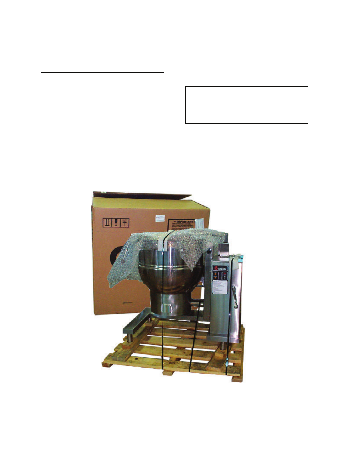
Inspection & Unpacking
The unit will arrive in a heavy shipping carton
and will be bolted or banded to a skid.
Immediately upon receipt, inspect the carton
carefully for exterior damage.
CAUTION
SHIPPING STRAPS ARE UNDER TENSION
AND CAN SNAP BACK WHEN CUT. TAKE
CARE TO AVOID PERSONAL INJURY OR
DAMAGE TO THE UNIT BY STAPLES LEFT
IN THE WALLS OF THE CARTON.
Carefully cut any polyester straps around the
carton and detach the sides of the box from the
skid. Pull the carton up off the unit.
Thoroughly inspect the unit for hidden damage.
Report any shipping damage or incorrect
shipments to the delivery agent.
Write down the model number, serial number,
and installation date, and retain this information
for future reference. Space for the
se entries is
provided at the top of the Service Log at the
back of this manual. Keep this manual on file
and available for operators to use.
CAUTION
THIS UNIT WEIGHS BETWEEN 535 AND
978 POUNDS (245 TO 400 Kg) DEPENDING
ON SIZE. INSTALLER SHOULD USE
PROPER EQUIPMENT TO LIFT SAFELY.
When installation is to begin, carefully cut any
straps which hold the unit on the skid. Lift the
unit straight up off the skid. Examine packing
materials to be sure loose parts are not
discarded with the materials.
6 GROEN.COM
OM-DH
OM-DH
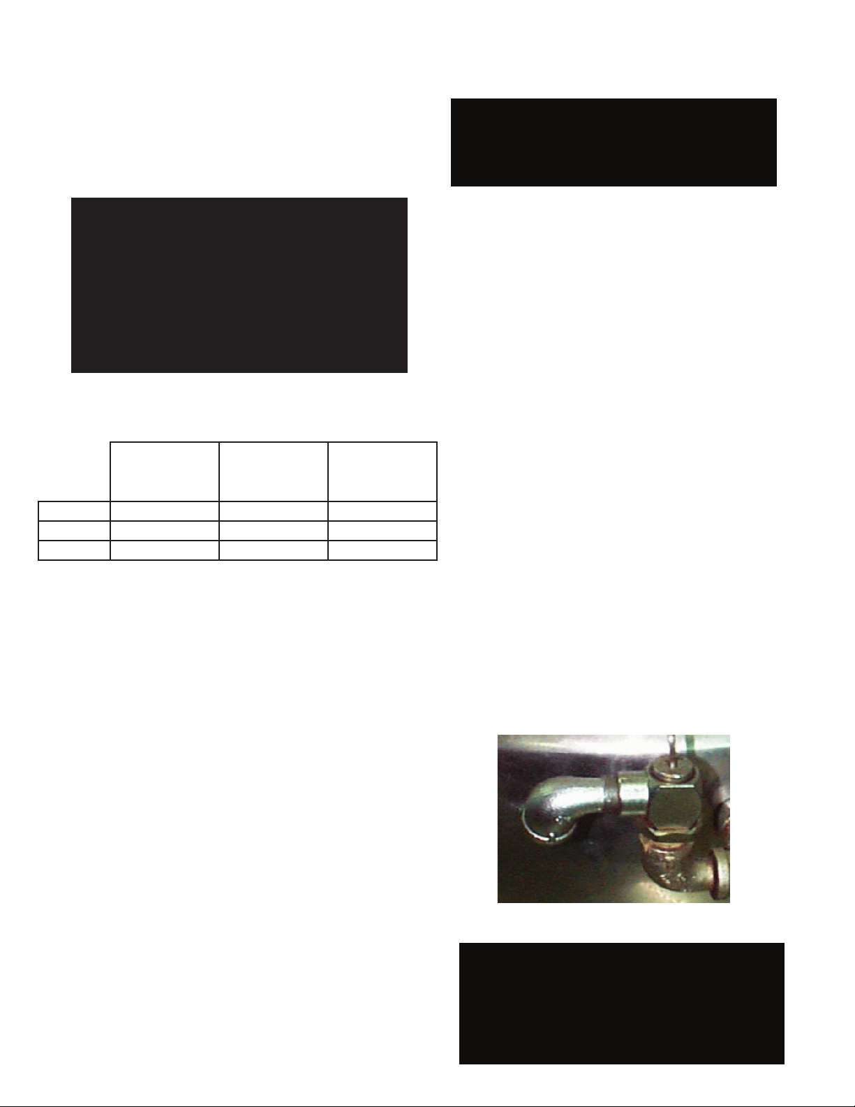
The open end of the pressure relief valve elbow
must face downward.
Installation
For efficient performance the DH kettle must be
installed in a well-ventilated area. Items which might
restrict or obstruct the flow of air for combustion and
ventilation must be removed. The area directly
around the appliance must be free of combustible
materials.
1. Installation can be on a combustible or
noncombustible floor. Clearences should be per
table below.
2.
The kettle should be installed in an adequately
ventilated room with provision for adequate air
supply. The ventilation must employ a vent hood and
exhaust fan with no direct connection between the
vent duct and the kettle flue. Do not obstruct the flue
or vent duct after installation.
3. Set the kettle in place and level it using a spirit
level on the bar rim, by turning the bullet or flange
feet to adjust leg length. Allow clearance around
the unit for cleaning, maintenance and service.
4.
Complete the piping to the gas service main with
½” line or approved equivalent.
5.
For standard units, provide 115 vac, 60 Hz,
single phase 5 AMP electrical service.
The unit
may also be ordered for alternate electric service
of 208 VAC or 240 VAC. Observe local codes
and/or The National Electrical Code in accordance
with ANSI/NFPA 70 (current edition), or the Canadian
Electrical Code, CSA C22.2 (current edition), as
applicable. Use the wiring diagram inside the service
panel and at the rear of this manual
6. Bring electrical service through the entrance at
the rear of the support housing with a ½ inch
conduit connector. Make a watertight connection
with the incoming lines.
8.
The gas supply and unit’s installation must conform
with local codes or in the absence of local codes, with
the National Fuel Gas Code, ANSI Z223.1/NFPA 54
(current edition), or the Natural Gas and Propane
Installation Code CSA 149.1(current edition), as
applicable. Additionally following must be complied with:
THE AREA DIRECTLY AROUND THE APPLIANCE
MUST BE CLEARED OF ALL COMBUSTIBLE MATERIAL.
FAILURE TO FOLLOW THESE INSTRUCTIONS CAN
CAUSE BODILY INJURY AND /OR PROPERTY DAMAGE.
The appliance and its individual shut-off valve must
be disconnected from the gas supply piping system
during any testing at pressures in excess of ½ PSI
(3.45 kPa). The appliance must be isolated from the
gas supply piping system by closing its individual
manual shut-off valve during any pressure testing at
or less than ½
PSI (3.45 kPa).
After the kettle has been connected to the gas
supply, check all gas joints for leaks. DO NOT
USE FLAME TO CHECK FOR LEAKS. A thick
soap solution or other suitable leak detector
should be employed.
9.
10.
Confirm that the jacket water level is between
the gauge glass markers or inside the sight glass
port. If the level is low, follow instructions under
“Jacket Filling and Water Treatment,” Page 13.
11.
The open end of the elbow on the outlet of the
safety valve must face downward. If it does not,
turn it to the correct position.
7. Electrically ground the unit at the terminal
provided.
DANGER
ELECTRICALLY GROUND THE UNIT AT THE
TERMINAL PROVIDED. FAILURE TO GROUND
UNIT COULD RESULT IN ELECTROCUTION
AND DEATH.
WARNING
DO NOT CONNECT ANY PIPING TO THE PRESSURE
RELIEF VALVE. THE VALVE MUST BE FREE TO VENT
STEAM AS NEEDED. IMPOROPER INSTALLATION
WILL VOID THE WARRANTY!
THE ELBOW ATTACHED TO THE PRESSURE RELIEF
VALVE MUST POINT TO THE FLOOR.
THE UNIT MUST BE INSTALLED BY PERSONNEL WHO
ARE QUALIFIED TO WORK WITH GAS, ELECTRICITY
AND PLUMBING. IMPROPER INSTALLATION CAN
CAUSE INJURY TO PERSONNEL AND/OR DAMAGE
TO THE EQUIPMENT. THE UNIT MUST BE INSTALLED
IN ACCORDANCE WITH APPLICABLE CODES. THE
UNIT MUST BE INSTALLED BY A LICENSED PLUMBER
OR GAS FITTER WHEN INSTALLED WITHIN THE
COMMONWEALTH OF MASSACHUSETTS.
WARNING
Minimum
Clearance from
Combustible walls
Left Side 6 in. 0in. 6in.
Right Side 6 in. 0 in. 10 in.
Rear 10 in. 10. 12 in.
Minimum
Clearance from
Non-Combustible
walls
Recommended
Clearances
OM-DH/DHT 7
OM-DH
OM-DH
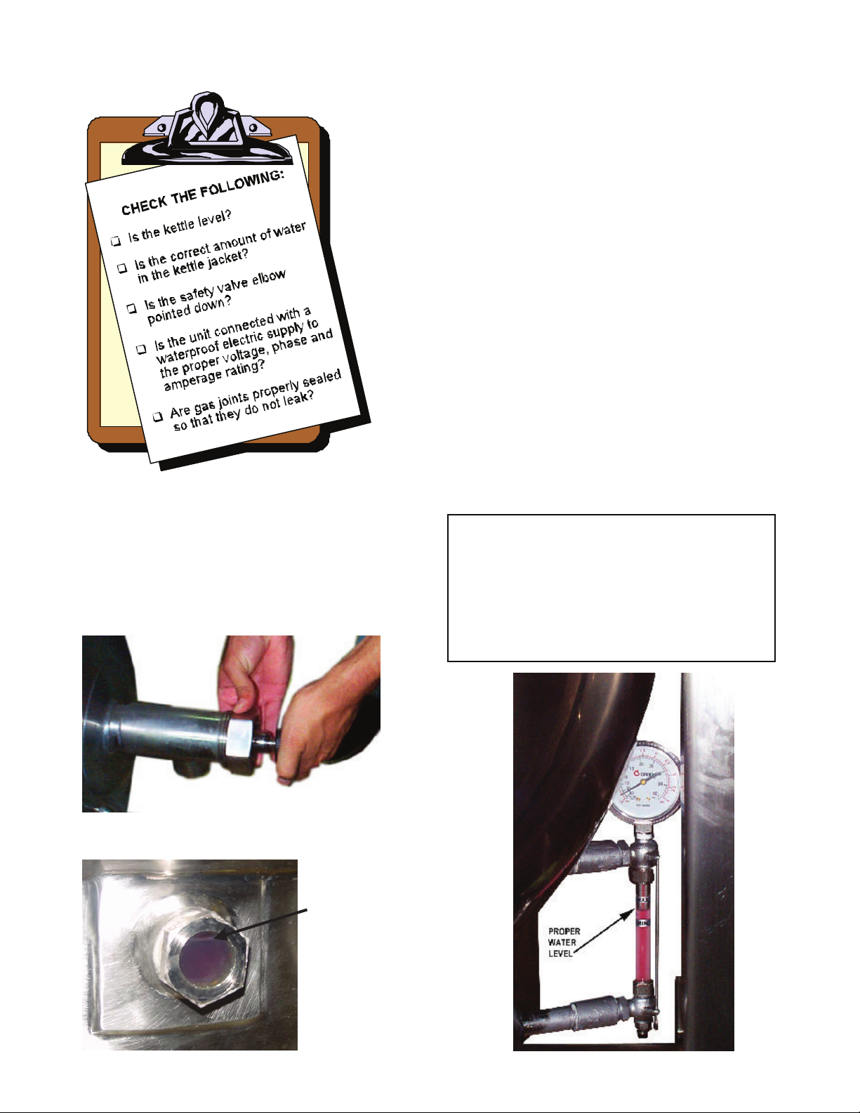
8
Each day confirm the jacket water
level by checking the water gauge.
When attaching the draw-off valve handtighten the nut.
(For units with optional tangent draw-off). Assemble
the tangent draw-off by placing the large nut over the
draw-off valve and inserting it into the draw-off tube.
ONLY HAND-TIGHTEN THE NUT to complete
installation.
Now that the kettle has been installed, you should
test to ensure that it is operating correctly.
1. Remove literature and packing materials from
inside and outside of the unit.
2. If the unit is equipped with a draw-off valve
(product outlet), clean out any material which
might clog or damage the draw-off.
3.
Confirm that the tilting mechanism is operating
properly by tilting the kettle through
its full range.
Then return the kettle to the upright position.
4. Turn on the electrical service to the unit.
5.
Pour 1-2 quarts of water into the kettle.
6. Following “To Start Kettle” instructions in the
“Operation” section (Page 9), begin heating the
water at the highest thermostat setting. The heat
indicator light should come on, and heating
should continue until the water boils.
If the unit functions as described it is ready for use. If
it does not function as described, contact your local
Groen Authorized Service Agency.
PROPER
WATER
LEVEL
Each day confirm the jacket water
level by checking the water gauge.
Now that the kettle has been installed, you should
test to ensure that it is operating correctly.
1. Remove literature and packing materials from
inside and outside of the unit.
2. If the unit is equipped with a draw-off valve
(product outlet), clean out any material which
might clog or damage the draw-o
ff.
3.
Confirm that the tilting mechanism is operating
properly by tilting the kettle through its full range.
Then return the kettle to the upright position.
4. Turn on the electrical service to the unit.
5.
Pour 1-2 quarts of water into the kettle.
6. Following “To Start Kettle” instructions in the
“Operation” section (Page 9), begin heating the
water at the highest thermostat setting. The heat
indicator light should come on, and heating
should continue until the water boils.
If the unit functions as described it is ready for use. If
it does not function as described, contact your local
Groen Authorized Service Agency.
WARNING
DO NOT STAND ON OR APPLY
UNNECESSARY WEIGHT OR PRESSURE ON
THE KETTLE FRONT OR POURING LIP. THIS
COULD RESULT IN THE OVERLOAD AND
FAILURE OF THE TILT MECHANISM, AND
POSSIBLE SERIOUS INJURY AND BURNS TO
THE OPERATOR AND OTHERS.
Now that the kettle has been installed, you should
test to ensure that it is operating correctly.
1. Remove literature and packing materials from
inside and outside of the unit.
2. If the unit is equipped with a draw-off valve
(product outlet), clean out any material which
might clog or damage the draw-off.
3. Confirm that the tilting mechanism is operating
properly by tilting the kettle through its full range.
Then return the kettle to the upright position.
4. Turn on the electrical service to the unit.
5. Pour 1-2 quarts of water into the kettle.
6. Following “To Start Kettle” instructions in the
“Operation” section (Page 9), begin heating the
water at the highest thermostat setting. The heat
indicator light should come on, and heating
should continue until the water boils.
If the unit functions as described it is ready for use. If
it does not function as described, contact your local
Groen Certified Service Agency.
Correct Water Level
13.
12.
14.
8 GROEN.COM
(Model DH-80E
& DHT-80 only)
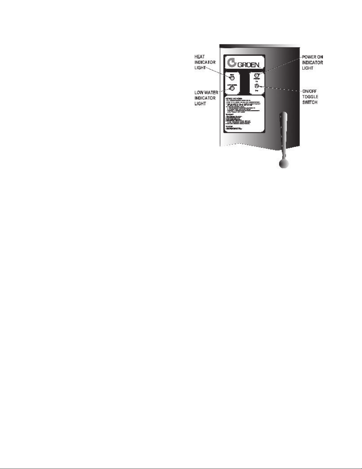
Operation
A.
Controls
Operator controls for the DH kettle are:
1.
Manual gas valve (on gas line behind the unit),
which controls the supply of gas from the main to
the unit.
2. On-Off (Toggle) Switch. This controls the supply
of electric power to the control circuits.
3. Thermostat dial, which turns the thermostat on or
off, and sets the kettle temperature.
4. Tilting crank, used to tilt the kettle body.
5. Indicator Lights to alert operator of unit
conditions:
a. Power On Indicator - shows that the unit is
turned on
b. Heat Indicator - indicates that main gas is on
to produce steam in the kettle jacket.
c. Low Water indicator - shows that jacket
water is low
6.
Unit gas
pressure regulator adjustment - located
behind the access door in the kettle skirt.
B. Operating Procedure
1.
To Start Kettle:
a. EVERY DAY make sure that the jacket water
level is between the markers on the gauge
glass or inside the sight glass port. If the level
is too low, see “Jacket Filling and Water
Treatment” on page 13.
b. Check the pressure gauge. If the gauge does
not show 20 to 30 inches of mercury (Hg)
vacuum (that is a reading of 20 to 30 below 0
atmospheric pressure), see “Jacket Vacuum”
on page 13.
c. Do not attempt to light any burner with a
flame.Turn the manual gas valve ON (align
handle with gas line).
1) Turn toggle (on-off) switch ON. The
electronic ignition will attempt to light the
pilot for 90 seconds, or until it is lit. Once
lit, proceed to st
ep two.
2) Turn thermostat to desired setting. The
main gas burner will ignite, and will cycle
to maintain the set temperature. The
3) If the unit does not light, turn it off and
wait five minutes. Then follow the
instructions again.
2
To Empty Kettle:
a. To tilt the body of the kettle forward, turn the
hand crank on the front of the cabinet
counter-clockwise. The body will stay in the
position it holds when you stop cranking. To
return the kettle body to its upright position,
turn the crank clockwise.
b. Product may also be transferred by means of
the optional draw-off valve, if the kettle is so
equipped.
3.
To Shut Down Kettle:
a. Turn thermostat dial to OFF
.
b. Turn toggle switch to OFF.
4.
For a prolonged shut-down:
a. Follow the procedure above.
b. Turn the manual gas valve off (handle at
right angles to gas line).
c. Disconnect electric power from the unit.
heat indicator light will come on.
OM-DH/DHT 9

OM-DH
OM-DH
WARNING
WHEN TILTING KETTLE:
1)
WEAR PROTECTIVE OVEN MITT AND
PROTECTIVE APRON.
2) USE DEEP CONTAINER TO CONTAIN
AND MINIMIZE PRODUCT SPLASHING.
3) PLACE CONTAINER ON STABLE,
FLAT SURFACE, AS CLOSE TO
KETTLE AS POSSIBLE.
4) STAND TO RIGHT OF KETTLE WHILE
POURING — NOT DIRECTLY IN POUR
PATH OF HOT CONTENTS.
5) POUR SLOWLY, MAINTAINING
CONTROL OF KETTLE, AND RETURN
KETTLE BODY TO UPRIGHT POSITION
AFTER CONTAINER IS FILLED OR
TRANSFER IS COMPLETE.
6)
DO NOT OVERFILL CONTAINER.
AVOID SKIN CONTACT WITH HOT
CONTAINER AND ITS CONTENTS.
5.
If power fails:
a. Do not attempt to operate the unit until
electric power is restored.
b. When power comes back on, follow
directions “To Start Kettle,” above.
C.
Use of Common Accessories
1.
Lift-Off or Counterbalanced Cover
As with stock pot cooking, an optional cover can
speed up the heating of water and food products.
It helps retain heat and reduces the heat and
humidity in the kitchen. A cover can reduce
some product cook times and help maintain the
temperature, color and texture of products held
or simmered for longer periods.
Be sure the handle is secure on the lift-off cover
before using. ALWAYS use the handle to place
or remove cover from the kettle. Wear protective
oven mitts and apron
When putting a lift-off cover on the kettle,
position it on top of kettle rim, with its flat edge
facing the pouring lip.
WARNING
AVOID ALL DIRECT CONTACT WITH HOT
SURFACES AND HOT FOOD OR WATER
IN THE KETTLE. DIRECT CONTACT
COULD RESULT IN SEVERE BURNS.
When removing a lift-off cover:
a. Firmly grasp the handle, and lift the rear
edge (farthest from operator) 1-2” (3-5 cm)
to allow steam and water vapor to escape.
Wait 2-3 seconds.
b. Tilt cover to 45-60° angle to allow any hot
condensate or product to roll off cover back
into kettle.
c. Remove cover, ensuring that remaining hot
condensate or product does not drip on
operator, floor or work surfaces.
d. Place cover on safe, flat, sanitary, out-of-the-
way surface, or return to kettle.
CAUTION
DO NOT TILT KETTLE WITH LIFT-OFF
COVER IN PLACE. COVER MAY SLIDE
OFF, CAUSING INJURY TO OPERATOR.
2. Basket Insert
An optional kettle basket insert set (Tri-BC) will
assist in cooking water-boiled products including
eggs, potatoes, vegetables, shell fish, pasta and
rice. The nylon mesh liner must be used for
products smaller than the basket mesh size,
(approx. ¼” (6 mm). This includes rice and small
pasta shapes.
a. Allow for displacement of the three baskets
and product. This may mean only half filling
the kettle. Test baskets and product
displacement with the kettle OFF, and with
cold water in the kettle.
CAUTION
DO NOT OVERFILL THE KETTLE WHEN
COOKING, HOLDING OR CLEANING.
KEEP LIQUIDS AT LEAST 2-3” (5-8 cm)
BELOW THE KETTLE RIM TO ALLOW
CLEARANCE FOR STIRRING, BOILING
AND SAFE PRODUCT TRANSFER.
10 GROEN.COM

OM-DH
OM-DH
WARNING
AVOID ALL DIRECT CONTACT WITH HOT
FOOD OR WATER IN THE KETTLE. DIRECT
CONTACT COULD RESUL T IN SEVERE
BURNS.
b. Load baskets on a level, stable work
surface.
c. Lift loaded baskets with both hands. Get
help from another person if the basket is too
heavy for safe handling.
d. Slowly lower product into kettle and securely
hook basket to the “Y” frame.
e. When removing baskets with cooked
product, lift straight up, ensuring basket
bottoms clear the kettle rim and pouring lip.
Wear protective oven mitts and protective
apron.
f. Allow hot water to fully drain from product,
before moving basket away from the kettle.
Do not rest baskets on kettle rim or pouring
lip. If baskets are too heavy for individual to
lift and safely move, get help. Remove
product immediately from basket into
another container, being sure to avoid
contact with hot product and hot basket or...
g. Place baskets with food on a stable, flat
surface, inside a solid steamer or bake pan,
to catch any remaining hot water draining
from product.
Sequence of Operation
The following “action-reaction” outline is provided to
help understand how the DH kettle works.
1.
When the power switch is turned on, it starts the
spark igniter and opens the automatic valve for
the pilot burner. The spark ignites a pilot flame,
which heats the sensor. The sensor then sends
a signal to turn off the spark. The flame
thereafter acts as a standing pilot until the power
is turned off.
2.
If the pilot flame is not sensed within 90 seconds
after spark begins, a timer shuts down the entire
operation. To attempt a second trial for ignition,
turn off the power switch. Check the gas supply
valves and wait five minutes before trying again
by switching power on. If you cannot establish a
pilot flame in four tries, close all valves, turn off
the power, and contact an authorized Groen
Service Agency.
3. When the operator sets a temperature on the
thermostat, it causes the automatic valve to
admit gas to the main burner, where it is ignited
by the pilot flame. When the kettle reaches the
set temperature, the thermostat switch opens.
This stops the signal to the gas control valve and
shuts off gas to the main burner. The pilot flame
remains lit. When the kettle cools below the set
temperature, the thermostat switch closes and
starts another cycle. On and off cycling
continues and maintains the kettle at the desired
temperature. This action is indicated by the Heat
indicator light.
The kettle has the following safety features in
addition to the 90-second ignition timer:
1. Low water cutoff relay that will shut off gas
supplies to all burners until the jacket water level
is corrected.
2.
High limit pressure switch, set to open at about
46 PSI and to shut down the burners until jacket
pressure is decreased.
3. Pop safety valve, which will release steam if
jacket pressure exceeds 50 PSI.
4. Tilt switch, which shuts off all burners when the
kettle is tilted.
5. Gas pressure regulator built into the gas control
valve.
OM-DH/DHT 11
 Loading...