

Groen HY-3E, 2HY-3E, 3HY-3E Operator's Manual
P IMPORTANT INFORMATION P KEEP FOR OPERATOR P IMPORTANT INFORMATION P
OPERATOR MANUAL OM-HY-3E
Part Number 121004 - Rev. B DOMESTIC
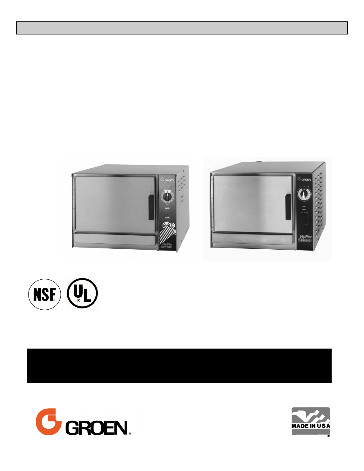
MODELS: HY-3E,(2)HY-3E, (3)HY-3E
HyPerSteam™
Atmospheric Convection
Steamer
Self-Contained
Electric Heated
Capacity: 3 Steamer Pans [per cavity]
(12" x 20" x 2½”)
New Model
Old Model
THIS MANUAL MUST BE RETAINED FOR FUTURE REFERENCE. READ,
UNDERSTAND AND FOLLOW THE INSTRUCTIONS AND WARNINGS
CONTAINED IN THIS MANUAL.
FOR YOUR SAFETY
DO NOT STORE OR USE GASOLINE OR OTHER FLAMMABLE VAPORS AND
LIQUIDS IN THE VICINITY OF THIS OR ANY OTHER APPLIANCE.

OM-HY-3E
IMPORTANT — READ FIRST — IMPORTANT
WARNING: THE UNIT MUST BE INSTALLED BY PERSONNEL QUALIFIED TO WORK WITH
ELECTRICITY AND PLUMBING. IMPROPER INSTALLATION CAN CAUSE INJURY TO
PERSONNEL AND/OR DAMAGE TO THE EQUIPMENT. THE UNIT MUST BE INSTALLED IN
ACCORDANCE WITH APPLICABLE CODES.
CAUTION: SHIPPING STRAPS ARE UNDER TENSION AND CAN SNAP BACK WHEN CUT.
CAUTION: DO NOT INSTALL THE UNIT IN ANY WAY WHICH WILL BLOCK THE RIGHT OR LEFT SIDE
VENTS, OR WITHIN 12 INCHES OF A HEAT SOURCE SUCH AS A BRAISING PAN, DEEP
FRYER, CHAR BROILER OR KETTLE.
CAUTION: LEVEL THE UNIT FRONT TO BACK, OR PITCH IT SLIGHTLY TO THE REAR, TO AVOID
DRAINAGE PROBLEMS.
WARNING: TO AVOID DAMAGE OR INJURY, FOLLOW THE WIRING DIAGRAM EXACTLY WHEN
CONNECTING A UNIT.
CAUTION: DO NOT USE PLASTIC PIPE. DRAIN MUST BE RATED FOR BOILING WATER.
WARNING: DO NOT CONNECT THE DRAIN DIRECTLY TO A BUILDING DRAIN.
WARNING: BLOCKING THE DRAIN IS HAZARDOUS.
IMPORTANT: Improper drain connection will void warranty.
IMPORTANT: Do not allow any water traps in the line. A trap can cause pressure to build up inside the
cavity during steaming, which will make the door gasket leak.
WARNING: WHEN YOU OPEN THE DOOR, STAY AWAY FROM STEAM COMING OUT OF THE UNIT.
STEAM CAN CAUSE BURNS.
WARNING: BEFORE CLEANING THE OUTSIDE OF THE STEAMER, DISCONNECT THE ELECTRIC
POWER SUPPLY. KEEP WATER AND CLEANING SOLUTIONS OUT OF CONTROLS AND
ELECTRICAL COMPONENTS. NEVER HOSE OR STEAM CLEAN ANY PART OF THE UNIT.
WARNING: ALLOW COOKING CHAMBER TO COOL BEFORE CLEANING.
WARNING: CAREFULLY READ THE WARNINGS AND FOLLOW THE DIRECTIONS ON THE LABEL OF
EACH CLEANING AGENT. USE SAFETY GLASSES AND RUBBER GLOVES AS
RECOMMENDED BY DELIMING AGENT MANUFACTURER.
WARNING: DO NOT MIX DE-LIMING AGENTS (ACID) AND DE-GREASERS (ALKALI).
WARNING: DO NOT PUT HANDS OR TOOLS INTO THE COOKING CHAMBER UNTIL THE FAN HAS
STOPPED TURNING.
WARNING: DO NOT OPERATE THE UNIT UNLESS THE REMOVABLE RIGHT SIDE PANEL HAS BEEN
RETURNED TO ITS PROPER LOCATION.
NOTICE: DO NOT USE A CLEANING OR DE-LIMING AGENT THAT CONTAINS ANY SULFAMIC ACID
OR ANY CHLORIDE, INCLUDING HYDROCHLORIC ACID. IF THE CHLORIDE CONTENT OF
ANY PRODUCT IS UNCLEAR, CONSULT THE MANUFACTURER.
NOTICE: DO NOT USE ANY DE-GREASER THAT CONTAINS POTASSIUM HYDROXIDE OR SODIUM
HYDROXIDE OR THAT IS ALKALINE.
WARNING: USE OF ANY REPLACEMENT PARTS OTHER THAN THOSE SUPPLIED BY GROEN OR
THEIR AUTHORIZED DISTRIBUTOR VOIDS ALL WARRANTIES AND CAN RESULT IN
BODILY INJURY TO THE OPERATOR AND DAMAGE THE EQUIPMENT. SERVICE BY
OTHER THAN FACTORY-AUTHORIZED PERSONNEL WILL VOID ALL WARRANTIES.
WARNING: HIGH VOLTAGE EXISTS INSIDE CONTROL COMPARTMENTS. DISCONNECT FROM
BRANCH BEFORE SERVICING. FAILURE TO DO SO CAN RESULT IN SERIOUS INJURY OR
DEATH.
2

OM-HY-3E
Table of Contents
OPERATOR WARNINGS .................................................................... 2
REFERENCES ............................................................................. 3
EQUIPMENT DESCRIPTION ................................................................. 4
INSPECTION AND UNPACKING .............................................................. 4
WATER CONDITIONING/REQUIREMENTS ..................................................... 4
INSTALLATION AND START-UP INSTRUCTIONS ................................................ 6
OPERATING INSTRUCTIONS ............................................................... 10
CLEANING ............................................................................... 12
MAINTENANCE AND TROUBLESHOOTING .................................................... 14
PARTS LIST .............................................................................. 15
SCHEMATICS [New Models] ................................................................. 18
SCHEMATICS [Old Models] .................................................................. 19
SERVICE LOG ............................................................................ 22
WARRANTY PROTECTION ................................................................. 23
References
UNDERWRITERS LABORATORIES, INC.
333 Pfingsten Road
Northbrook, Illinois 60062
KLENZADE SALES CENTER
ECOLAB, Inc.
370 Wabasha
St. Paul, Minnesota 55102
800 328-3663 or 612 293-2233
NATIONAL FIRE PROTECTION
ASSOCIATION
60 Battery March Park
Quincy, Massachusetts 02269
NFPA/70 The National Electrical Code
NATIONAL SANITATION FOUNDATION
3475 Plymouth Road
Ann Arbor, Michigan 48106
3
OM-HY-3E
Equipment Description
Your Groen HY-3E HyPerSteam Convection
Steamer is designed to give years of service. It has
a stainless steel cavity (cooking chamber) which is
served by an independent atmospheric steam
generator which is electrically-heated. A powerful
blower circulates the steam in the cavity to increase
heating efficiency.
The cavity holds up to three steam table pans (12" x
20" x 2½" deep). A 16 gauge stainless steel case
encloses the cavity, the steam generator and the
control compartment that houses electrical
components. Door hinges are reversible (the door
may be set to open from the left or right). Operating
Controls are on the front panel.
Newer model HY-3E steamers (manufactured since
February, 1999) are equipped with fully electronic
controls and a button-activated, pre-programmed
CLEAN cycle. These units are readily identified by
their unique control panels. The On-Off switch on
older models has been replaced by touch pad
controls, and the distinctive symbol for steam is
integrated into the panel. The new models also have
fewer panel louvers on the right side.
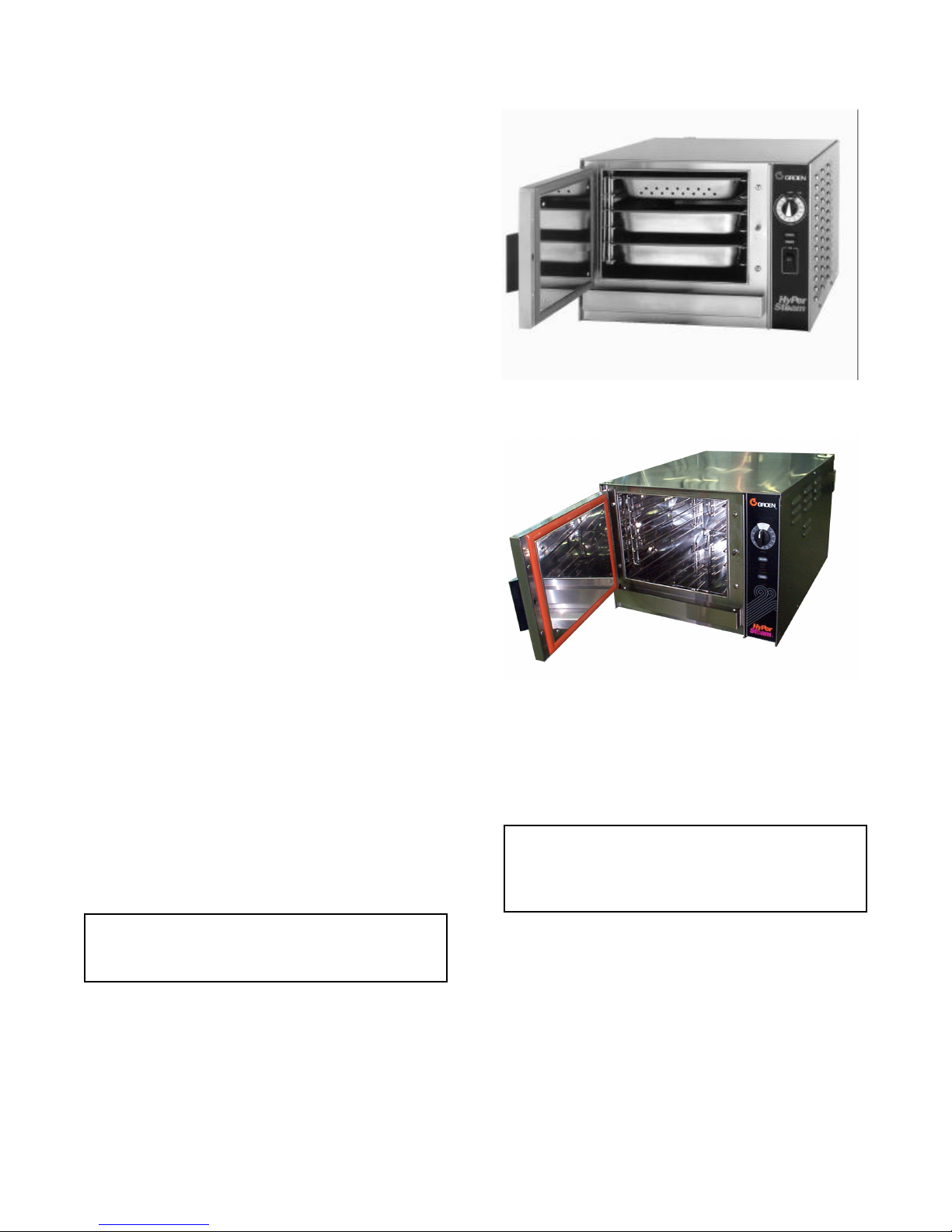
The HY-3E steamer holds three standard 12"x
20"x 2-½" deep pans [old model shown].
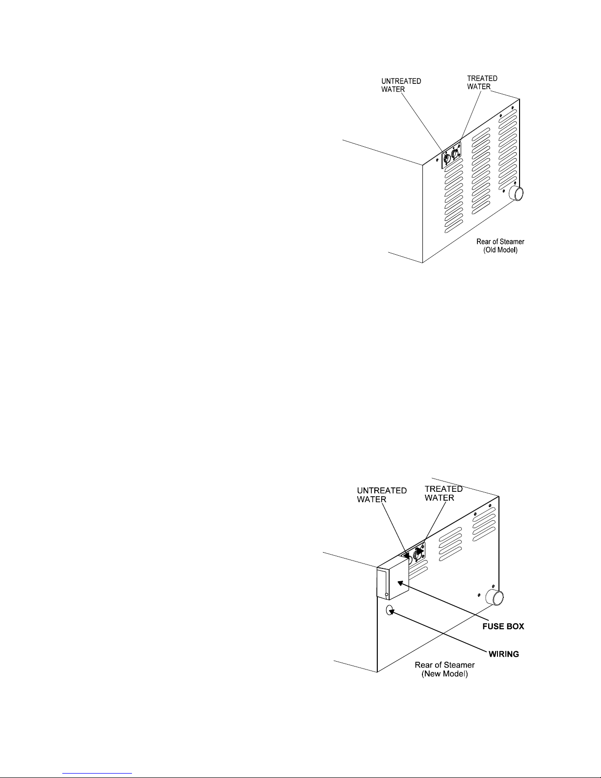
From the rear the newer unit is distinguished by the
addition of a “fuse box” which allows the operator to
change fuses without removing panels.
The drain system on all models includes a spray
condenser, which helps keep steam from escaping
from the chamber and cools drain water.
Inspection and Unpacking
The HY3-E will be delivered completely assembled in
a heavy shipping carton attached to a skid. On
receipt, inspect the carton carefully for exterior
damage.
CAUTION
SHIPPING STRAPS ARE UNDER TENSION AND
CAN SNAP BACK WHEN CUT.
Carefully cut the straps around the carton and detach
the sides of the carton from the skid. Pull the carton
up off the unit. Be careful to avoid personal injury or
equipment damage from staples which might be left in
the carton walls.
The new model can be identified by its unique
control panel, and fewer side panel louvers.
CAUTION
THIS UNIT WEIGHS 180 POUNDS (82 KG). YOU
SHOULD GET HELP AS NEEDED TO LIFT THIS
WEIGHT SAFELY.
Write down the model number, serial number and
installation date. Keep this information for reference.
Space for these entries is provided at the top of the
Service Log in the back of this manual.
When starting installation, lift the unit straight up off
the skid. Check packing materials to make sure
loose parts such as the condensate drip tray are not
discarded with this material.
4
Water Conditioning
It is essential to supply the steam generator with water
that will not form scale. Even though the steam
generator is engineered to minimize scale formation,
scale development depends on water hardness and
the number of hours per day you operate the
equipment. In some areas, water is low enough in
mineral content to avoid scale formation. But most
water supplies are full of minerals which form scale. It
is this scale which could lead to an early component
failure.
Your water utility can tell you about the minerals in your
water. For the steam generator's water level sensing
system to function properly, the water must conduct
electrical current. This typically requires it to have a
minimum of 40 parts per million (ppm) total dissolved
solids (TDS) as measured with a Groen Test Kit (P/N
110889). At high TDS concentrations, however,
serious scaling problems may occur. Consult your local
water utility for information and referral regarding
effective water treatment in your area. Please follow
these simple precautions:
1. Do not rely on unproven water treatments
which are sold for scale prevention or scale
removal. The best way to prevent scale is to
supply water with minimum levels of dissolved
solids (but at least 40 ppm TDS).
2. If your water contains scale-forming minerals, as
most water does, use a well-maintained water
softener. Whether an exchangeable softener
cartridge or a regenerating system is chosen, a
regular replacement or regeneration program is
essential.
OM-HY-3E
The optional second water connection can reduce
treated water requirements.
Since softener systems are typically sized by total
GPH (gallons per hour), the second intake could
reduce treatment requirements by up to 80%,
resulting in significant savings.
On the HY-3E, the twin water connections are side
by side on the rear of the unit. When facing the back
of the unit, the treated (softened) water intake is on
the right.
IMPORTANT: ENSURE ANY WATER TREATMENT
SYSTEM DELIVERS SUFFICIENT WATER VOLUME
AND FLOW RATE.
3. Installing a water meter between the softener and
the steamer will provide an accurate gauge of
water use, and will help determine when to
exchange cartridges or regenerate the softener.
Using a water softener will provide longer
generator life, higher steam capacity, and reduce
maintenance requirements.
4. If you notice a slowdown in steam production, have
the unit checked for scale build-up. Heavy scale
reduces the unit’s ability to boil water, and can
even cause heating elements in the steam
generator to overheat and burn out.
Groen Steamers are also available with an option for
two separate water intakes — one for the steam
generator (soft water), the other for the spray
condenser (untreated water). The steam generator
only uses 14 to 31% of a steamer’s water.
New models have a fuse box mounted on
the rear.
5
OM-HY-3E
Installation and Start-Up
WARNING
THE UNIT MUST BE INSTALLED BY PERSONNEL WHO ARE QUALIFIED TO WORK WITH ELECTRICITY
AND PLUMBING. IMPROPER INSTALLATION CAN CAUSE INJURY TO PERSONNEL AND/OR DAMAGE TO
THE EQUIPMENT. THE UNIT MUST BE INSTALLED IN ACCORDANCE WITH APPLICABLE CODES.
CAUTION
DO NOT INSTALL THE UNIT WITH THE RIGHT OR LEFT SIDE VENTS BLOCKED OR WITHIN 12 INCHES OF
A HEAT SOURCE (SUCH AS A BRAISING PAN, DEEP FRYER, CHAR BROILER OR KETTLE).
TO AVOID DRAINAGE PROBLEMS, LEVEL THE UNIT FRONT TO BACK.
1. Electrical Supply Connection
A. Panel Removal
Open the wiring and control panel by removing
two screws (three on new model) on the right
side panel. Slide the panel forward, and set it
aside.
B. Supply Voltage
The unit must be operated at the rated
nameplate voltage, plus or minus 10 percent.
C. Phase Selection
Refer to heater schematics (Pages 17 thru 20)
for wiring information.
CAUTION
THE UNIT MUST HAVE A SEPARATE GROUND
WIRE FOR SAFE OPERATION.
D. Terminal Block
The terminal block for incoming power is located
at the back of the control compartment. The
ground terminal is located in the wiring
compartment above the terminal block.
Minimum size for the ground wire is 10 AWG.
Supply wire
To determine the type of wire you need for the
power supply, find the operating voltage and
phase on the unit data plate. Refer to the table
below or to the label on the unit’s back for
correct wire size and temperature rating. The
“Electrical Supply Connection” label on back
right side of the unit gives directions for proper
connection of the terminal block jumpers. The
specified wire must be used, or the unit will not
meet Underwriters Laboratories and National
Electric Code requirements. The knockout hole
is sized for a ¾ inch conduit fitting.
WARNING
TO AVOID DAMAGE OR PERSONAL INJURY,
FOLLOW THE ELECTRICAL SCHEMATIC
EXACTLY WHEN CONNECTING THE UNIT..
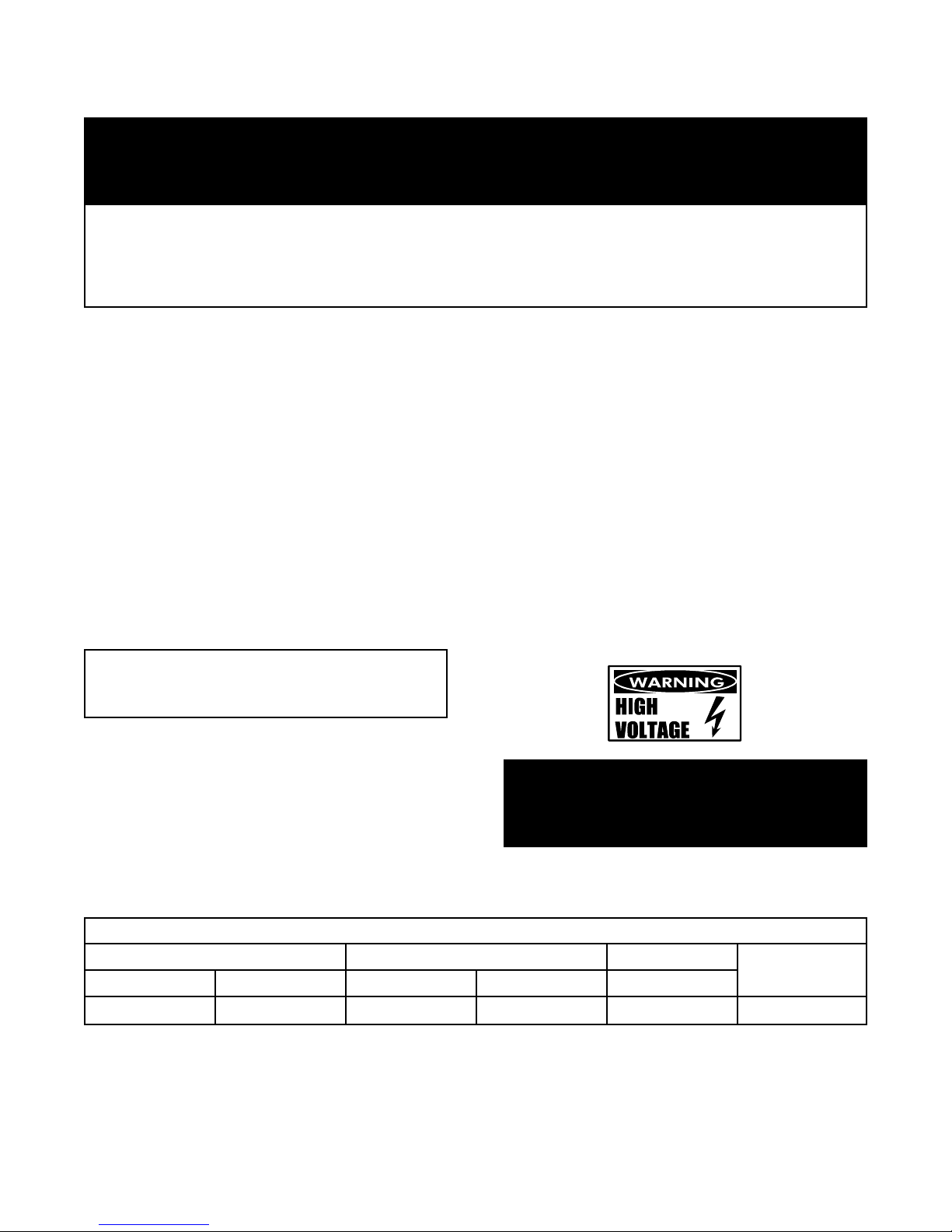
FIELD WIRING TABLE - USE ONLY COPPER WIRE
208 VOLT 240 VOLT 480 VOLT INSULATION
1 PHASE 3 PHASE 1 PHASE 3 PHASE 3 PHASE
8 AWG 10 AWG 8 AWG 10 AWG 14 AWG
ELECTRICAL SUPPLY CONNECTIONS
RATING
THHN (90ºC)
6
E. Branch Circuit Protection
Each HY-3E Steamer should have its own
branch circuit protection. Current and power
demands for the different units are as follows:
VOLTAGE PHASE AMPS MAX. KW
208
240
480 3 10 8
1
3
1
3
39
23
33
20
8
8
8
8
2. Water Connection(s)
Install a check valve to prevent back flow in the
incoming cold water line, as required by local
plumbing codes. Water pressure in the line
should be between 30 and 60 PSIG (210 and
420 kPa). If pressure is above 60 PSIG, a
pressure regulator will be needed.
A ¾ inch NH connector (garden hose type) is
used to attach the water supply to the inlet valve.
Minimum water feed line diameter is ½ inch
(13mm). Use a washer in the hose connection.
Do not allow the connection to leak, no matter
how slowly. For the twin water connection
option, treated (softened) water goes to the right
(facing the rear of the unit), and untreated water
to the left. Connections for both are made as
described above.
3. Drain Connection
Level the steamer front to back, or even pitch it
slightly to the rear by adjusting the bullet feet on
the stand or cabinet base.
A 1½ inch (38mm) ID hose may be attached to
the drain pipe (supplied).
OM-HY-3E
line. A trap can cause pressure build-up in the
cavity, which may cause the door gasket to leak.
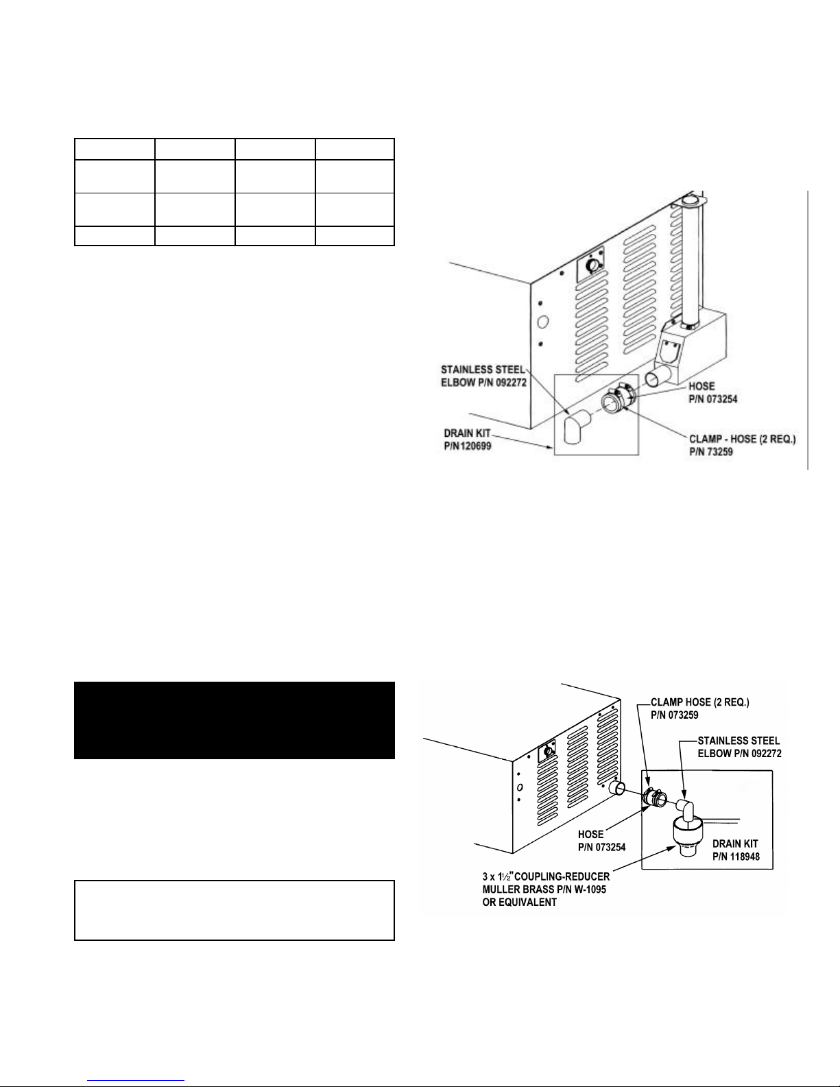
DRAIN LINE INSTALLATION
(OLDER MODELS WITH DRAIN BOX)
OPTION ONE: Use 1½” Drain Kit (P/N 118948) to
nearby floor drain, or from Stainless Elbow (P/N
092272), use “Radiator” Hose (rated at least 212oF),
and an additional clamp (P/N 073259).
OPTION TWO: Using the hose (P/N 073254) and
two hose clamps (P/N 073259), connect 1½” copper
tubing to the floor drain. NOTE: Drain lines must be
pitched downward approximately ¼” per foot.
No water traps are allowed in the drain line.
(NEW MODELS WITHOUT DRAIN BOX)
From the Muller Brass coupling-reducer (P/N W-
1095), connect 1½”“ copper tubing to the floor drain.
For stacked units use Drain Kit P/N 125777.
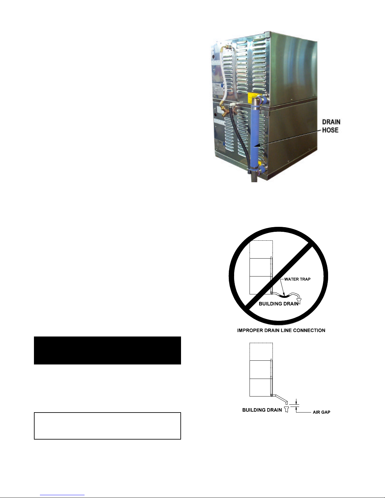
WARNING:
DO NOT CONNECT THE DRAIN DIRECTLY TO A
BUILDING DRAIN. BLOCKING THE DRAIN IS
HAZARDOUS.
There must be a free air gap between the end of
the hose and the building drain. The free air gap
should be as close as possible to the unit drain.
There must also be no other elbows or other
restrictions between the unit drain and the two
inch free air gap.
CAUTION
DO NOT USE PLASTIC PIPE. DRAIN MUST BE
RATED FOR VERY HOT WATER.
Install the drain line with a constant downward pitch.
IMPORTANT: Do not allow water traps in the
7
OM-HY-3E
4. Factory Stacked Units
This section is applicable only if you are installing
factory-mounted stacked units. If you plan to stack
steamers yourself, whether purchasing a new one for
stacking or a kit to stack two units you already own,
you will require OM-HY-3E(S), RETROFIT
SUPPLEMENT (Part Number 121014).
Installing the (2) HY-3E and (3) HY-3E stacked
steamers is similar to installing a single unit. The
steamers are stacked and assembled at the factory
and delivered with the water connections and drain
hoses required for a single point connection.
a. Water Connection
As the drawings on Page 10 show, the same
water supply connection is used. At the water
inlet valve a ¾ inch NH connector (garden hose
type) is used for the water supply. If you have
the second water connection option, there are
two connections to be made. Treated water
(softened) is connected to the right valve fitting
(facing the rear of the unit) and untreated water
to the left valve fitting.
b. Electrical Supply Connection
Rear view of (2) HY-3E — Note: The drain
hoses, required for installation, are packed
inside one of the steamer cavities.
Separate, individual electrical connections
will be required for each steamer in the stack.
We also strongly recommend that each HY3E Steamer have its own branch circuit
protection.
c. Drain Connection
HY-3E steamers must be leveled front to back,
or pitched slightly to the rear by adjusting the
bullet feet on the cabinet or stand base.
A 1½ inch (38.1 mm) ID hose may be attached
to the unit drain. It must be rated for very hot
water.
WARNING
DO NOT CONNECT THE UNIT DRAIN DIRECTLY
TO THE BUILDING DRAIN.
Ensure that there is a free air gap between the end
of the unit drain and the building drain. This gap
should be as close as possible to the unit drain. Do
not allow elbows or restrictions between the unit and
the free air gap.
CAUTION
DO NOT USE PLASTIC PIPE. DRAIN MUST BE
RATED FOR VERY HOT WATER.
Install the line with a constant downward pitch.
Proper Drain Line Connection — Drain Line
must have a constant downward pitch of at
least ¼” per foot.
8
 Loading...