

Page 1
INSTRUCTION SHEET
Intek Steamer Knockdown Stand
Assembly and Steamer Mounting
Introduction:
The 170944 Intek Steamer Stand is shipped in a compact, knockdown form. Assembly on site
is required before attempting to mount the steamer(s). The instructions below will guide you
through the process. All of the hardware required to assemble the stand and mount the
steamer(s) is included.
1.0 Stand Assembly
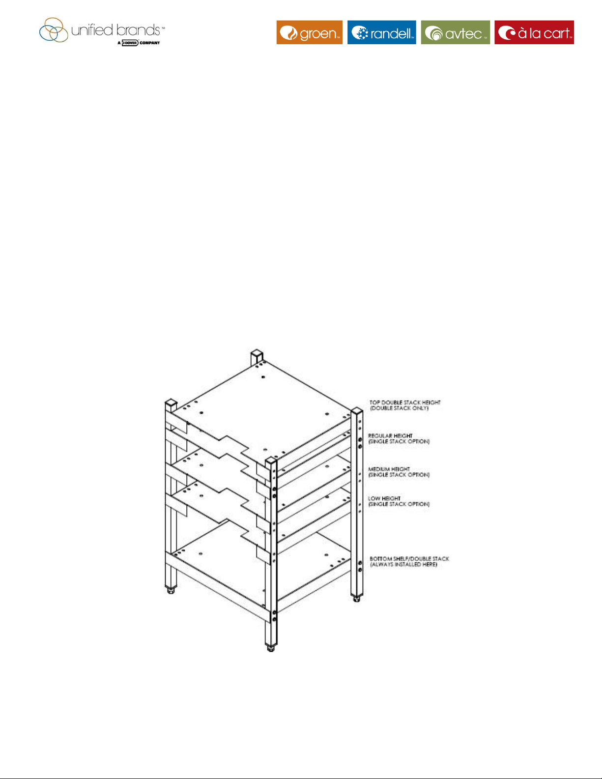
1.1 Determine the shelf position locations most appropriate to the location. There are two
shelves supplied with the stand and both must used to provide proper stability. The lower shelf
always mounts in the bottom position. The upper shelf mounts in one of four positions,
depending upon whether a single steamer is being mounted or a pair of steamers are being
double-stacked. The upper shelf always mounts in the topmost position when a pair of
steamers are mounted.
1.2 The above figure shows the shelf orientation for a single steamer, where the cutout in
the lower shelf is turned to the back of the stand. For a double-stack stand, turn the shelf so the
cut-out faces to the front.
170720 Rev. B
Page 1
Page 2
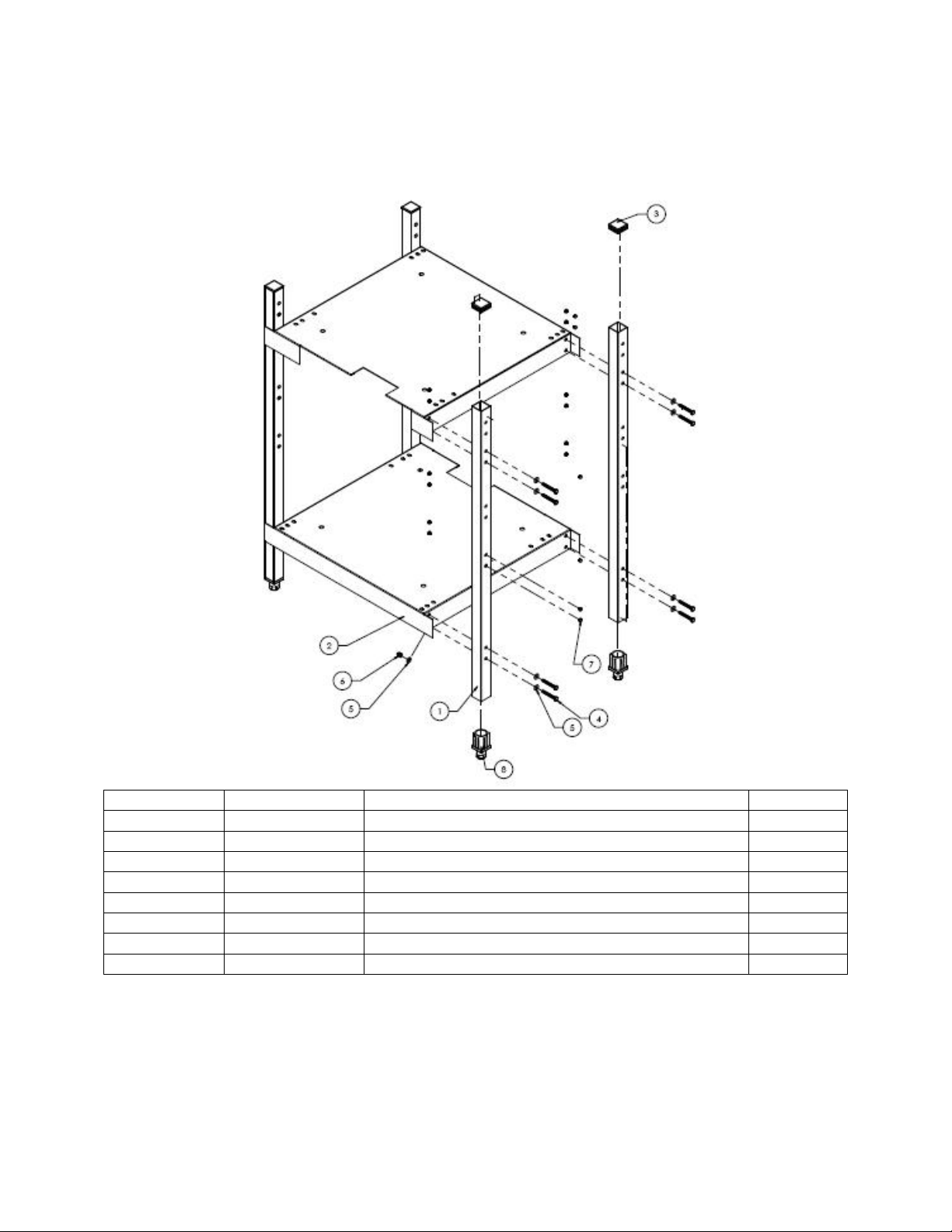
1.3 Attach each shelf (Item 2) to the stand with eight 2” hex-head screws (Item 4), inserting
the screws through the legs. Install a washer (Item 5) under the head of the screw and under
the dome nut (Item 6) holding the screw, as shown below. Square up and tighten the stand
before installing the steamer(s).
Item No Part No Description Qty
1 170719 Leg, Intek Steamer Stand 4
2 170718 Shelf, Intek Steamer Stand 2
3 142684 End Plug, 1-1/2” Square Tube 4
4 156055 Screw, Hex Head, ¼-20 x 2” 16
5 005472 Washer, Plain, ¼” 32
6 090567 Nut, Dome, ¼-20 16
7 129788 Plug, Hole, 9/32” 48
8 042505 Foot Insert, Bullet 4
1.4 Install the four plastic end caps (Item 3) in the top of the stand legs (Item 1) as shown.
Install the four bullet foot inserts (Item 8) in the bottom of the legs as shown. The plugs and feet
install with a gentle tap from a mallet.
1.5 Use the 48 hole plugs ((Item 7) to close off any unused mounting holes in the steamer
stand legs, as shown.
170720 Rev. B
Page 2
Page 3
1.6 If the stand is to have casters or flanged feet, they are supplied in separate kits. See the
instructions provided and install the casters or flanged feet in place of the bullet feet.
2.0 Steamer Installation
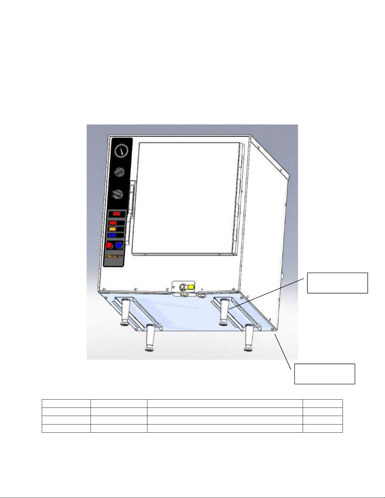
2.1 Prepare the Intek steamer by loosening and removing the four short legs and the four
screws on the base. Refer to the diagram below. Set the legs aside as they will be replaced
with machine screws included in the stand kit.
Hex screws (4)
that are removed
Item No Part No Description Qty
7 129788 Plug, Hole, 9/32” 48
9 005449 Screw, Hex Head, 3/8-16 5/8” 8
10 005830 Washer, 3/8” 8
Legs (4) that are
removed
Page 3
170720 Rev. B
Page 4

2.2 Set the Intek steamer on the stand upper shelf as shown and re-attach the drain pan
rails using four 3/8-16 5/8” hex head machine screws (Item 9) and four 3/8 washers (Item 10).
Start the screws into the bottom of the steamer, but do not fully tighten them until step 2.4.
Steamer
with legs removed
Drain Pan
Slides (2)
3/8-16 5/8” Hex
Head Screws
2.3 [NOTE: the following step is optional – the machine screws are not needed for structural
integrity of the steamer or the stand.]
Reinstall the four smaller hex head machine screws that were removed from the underside of
the steamer through the holes in the edges of the stand shelf. Two screws are used on the left
and on the right underside of the steamer. There are 6 holes on each side of the shelf to match
the patterns on the three Intek Steamer models (4-Pan and 6-Pan electric; and 5-Pan gas).
Page 4
170720 Rev. B
Page 5
2.4 Tighten all four screws holding the drain pan rails to the shelf. Install hole plugs in any
unused holes in the shelf that are visible after the steamer has been attached.
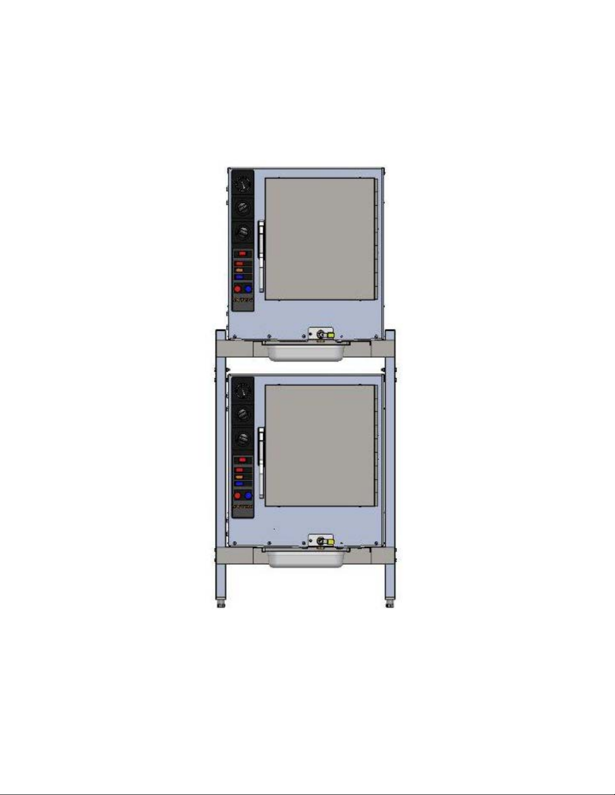
2.5 If a second steamer is provided, install it on the lower shelf in the same manner as the
first, using steps 2.1 through 2.4.
2.6. Note that the steamers mount directly to the shelves and the drain pans (standard 12 x
20 x 4” hotel pan) slide into the rails mounted underneath the shelves.
1055 Mendell Davis Drive, Jackson, MS 39272 • 888.994.7636 • 888.864.7636 • unifiedbrands.net
ADDITIONAL MANUFACTURING LOCATION: 525 SOUTH COLDWATER ROAD, WEIDMAN MI 48893
© 2009 Unified Brands. All Rights Reserved. Unified Brands is a wholly-owned subsidiary of Dover Corporation.
170720 Rev. B
Page 5
 Loading...