

Page 1
INSTRUCTION SHEET
Intek Water Drain Kit
Installation Instructions
Introduction:
The 161053 Intek Water Drain Kit is shipped as a collection of parts that allows the steamer
reservoir drain and condensate drain to be directed to a floor drain through a high-temperature
rubber hose. Assembly on site is required. The instructions below will guide you through the
process. All of the hardware required to assemble the hose and connect to the steamer is
included.
1.0 Unpacking
1.1 Remove all parts from the shipping carton.
WARNING: DISCONNECT ELECTRICAL POWER AND THE GAS LINE (IF USED)
FROM THE STEAMER BEFORE INSTALLING THE DRAIN KIT.
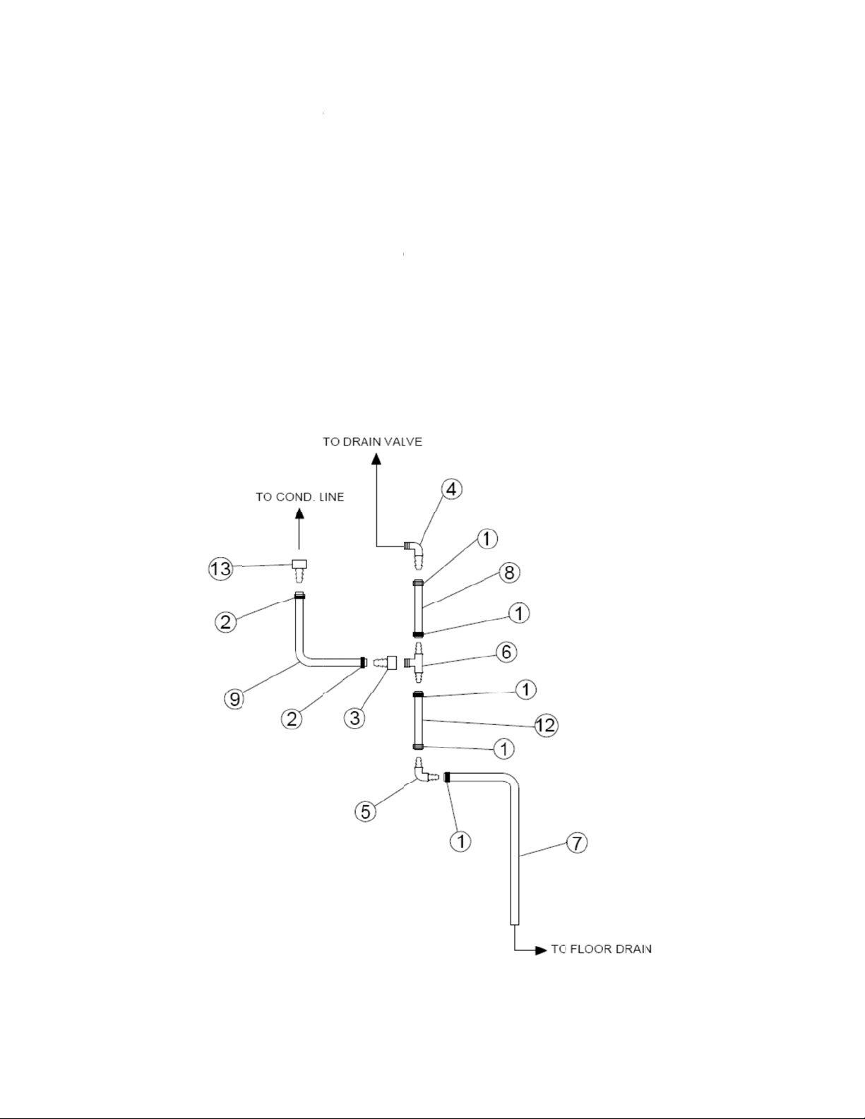
2.0 Verify Parts
2.1 Locate parts and verify the correct quantities listed below were included in the carton.
Check the packing materials for any missing parts.
ITEM P/N DESCRIPTION QTY UOM
1 099284 CLAMP HOSE WORM DRIVE 5 EA
2 127523 CLAMP, CONSTANT TENSION 2 EA
3 142262 ADAPTER, 1/2" FPT TO 3/8" BARB 1 EA
4 142548 1/2" NPT TO 3/4' BARB, 90 DEG ELBOW 1 EA
5 142549 3/4" HOSE BARB, 90 DEG. ELBOW 1 EA
6 143244 BRANCH TEE, 3/4" HOSE BARB TO 1/2" NPT 1 EA
7 143250 HOSE, 3/4" ID, 10 FT LONG 1 EA
8 143251 HOSE, 3/4" ID, 3.5-IN LONG 1 EA
9 143254 HOSE, 3/8" ID, 30-IN LONG 1 EA
10 158591 DRAIN PAN 1 EA
11 162992 10-24 SHOULDER SCREW, LOW PROFILE 2 EA
12 160133 HOSE, 3/4" ID, 7-IN LONG 1 EA
13 162993 ADAPTER, 3/8”FPT TO 3/8” BARB 1 EA
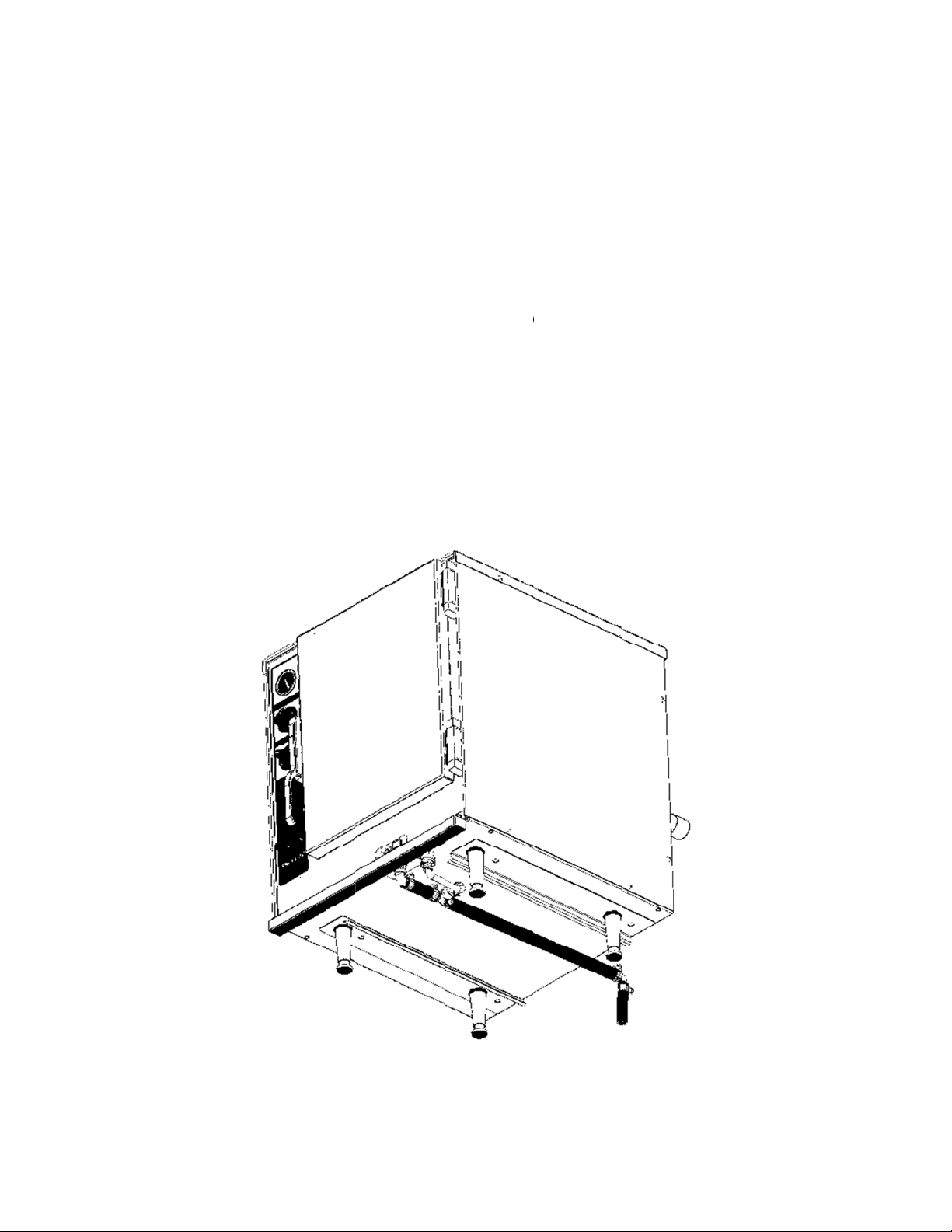
3.0 Water Drain Installation
3.1 Remove the right side panel from the steamer to provide access to the condensate drain
connection. The condensate runs from the bottom of the copper condenser to a 90
degree barb elbow on the bottom of the steamer. The elbow is secured to the bottom
with a nut.
Page 1
159343 Rev. C
Page 2
3.2
Rth
n
R
T
o
A
E
n
o
n
n
o
h
e
e
t
1
5
]
a
p
a
”
e
3
0
t
a
h
3
n
s
b
e
g
a
[
c
d
n
-
s
s
b
0
2
i
w
s
n
1
e
m
e
t
o
e
h
e
T
B
3.3 I
3.4
3.5
3.5
emove the
e connecti
stall one e
b
arb outlet a
eattach the
hread the h
u
nderneath t
t
ward the r
ssemble th
[I
em 6], the
lbow [Item
h
ose clamps
2
on the 3/8
ut and repl
n securely.
d of the su
d secure w
right side p
se drain ¾
e steamer.
ar of the st
drain asse
/2 FPT to
] and the 1
[Item 1] on
hose conne
ce it with t
plied hose
ith a consta
nel on the
barbed el
Tighten th
amer
mbly startin
/8 Barb Ad
foot hose
he ¾ hose
ctions.
e 3/8” FPT
/8" inside
t tension cl
teamer.
ow [Item 4]
connectio
with the 3
pter [Item 3
Item 7] as
onnection
to 3/8” bar
iameter x 3
amp [Item
onto the un
securely
1/2 inch ho
], the 7 inch
hown in the
and the co
adapter [It
" long [Ite
].
t drain valv
ith the barb
e [Item 8],
hose [Item
drawing be
stant tensi
m 13]. Tig
7] onto th
opening
end facing
he ¾ Barb
12], the ¾
low. Use th
n clamps [I
ten
3/8”
ee
arb
e
tem
59343 R
Page 2
v. C
Page 3
n
C
w
C
A
w
o
a
T
o
x
3
s
g
w
o
t
e
d
n
e
[
u
o
e
o
n
a
g
u
e
l
p
a
s
u
t
w
e
e
o
a
a
m
t
p
a
a
M
2
1
t
e
m
e
t
3.6 I
3.7
3.8
3.9
3.10 F
3.11 F
3.12
stall the sh
ut the 3/8”
ithout pinch
onnect the
d
rain hose a
10 foot len
ith the elbo
or single un
h
ose end mu
c
ntinuous d
or double s
f
cility drain.
he complet
rt hose en
30” hose [I
ing or kinki
/8" diamet
sembly.
th of hose
to help ro
its cut the l
st have at l
wnward sl
ack units, i
d hose inst
[Item 8] to
tem 9] to a l
g.
r x 30" lon
Item 7] is s
te the hos
ng hose to
ast a 2" ga
pe without
stall two kit
llation sho
he ¾” barb
ength that
hose loose
pplied with
to the prop
ength as n
from the fl
ny traps.
, one on e
ld appear
elbow [Ite
ill connect
end to the
this kit. It c
er drain loc
eded to rou
or drain.
ch steamer
s in Figure
4] on the d
o the drain
lastic barb
an be cut to
tion.
te it to a fac
ake sure th
and run bo
.
rain valve.
hose asse
fitting on th
length and
ility drain. N
e hose has
h hoses to
bly
used
ote
a
he
59343 R
Page 3
v. C
Page 4

4.0 Drain test
4.1 Test to ensure the final assembly of the drain line allows the water to flow freely. Loops
or kinks in the hose will cause back pressure which may cause the door to pop open
during draining.
WARNING: DO NOT CONNECT THE DRAIN DIRECTLY TO A BUILDING DRAIN.
BLOCKING THE DRAIN IS HAZARDOUS.
There must be a free air gap between the end of the hose and the building drain. The
free air gap should be as close as possible to the drain unit. There also must be no
other elbows or restrictions between the unit drain and the free air gap
CAUTION: DO NOT USE PLASTIC PIPE. THE DRAIN MUST BE RATED FOR
BOILING WATER.
5.0 Condensate Tray installation
5.1 Remove screws (D) and (E) from the lower right front of the steamer (see figure below)
and slide out the gutter strip that is sandwiched between the front face and the floor of
the steamer.
Page 4
159343 Rev. C
Page 5

R
S
S
l
Rof
H
e
g
e
f
n
u
t
o
p
o
d
e
o
s
e
e
w
e
s
d
T
m
1
]
(
e
a
e
a
a
5.2
5.3
5.4
5.5
einstall scr
crew (E).
imilarly on t
s
ide out the
einstall scr
screw (A).
ang the co
s
ould easily
a
ppear as sh
w (D) and
he lower lef
utter strip
ws (B) and
densate dri
fit over the
own below.
se a 10-24
front side
n the left si
(C). Use a
tray on th
two new sh
low profile
the steam
e.
10-24 low p
front of th
ulder scre
houlder scr
r, remove
rofile shoul
steamer.
s. The co
w [Item 11
crews (A),
er screw [It
he keyhole
pleted ste
in place of
B) and (C)
m 11] in pl
tabs on the
mer should
nd
ce
tray
now
59343 R
Page 5
v. C
Page 6

1
59343 Rev. C
Page 6
Page 7

6.0 F
T
p
a
m
d
M
a
k
)
J
p
o
2
e
w
g
6
O
e
w
T
l
6
O
b
1
u
w
r
e
6.1
stacked
inal Install
he installed
air of stea
tion Chec
drain line(s
ers with tw
should ap
separate l
ear as sho
ines. A sin
n below.
le unit wou
he figure ill
d only sho
strates a
a single lin
e.
1055 Men
ADDITIONAL
©
2009 Unified Br
ell Davis Drive,
ANUFACTURI
nds. All Rights
ackson, MS 39
NG LOCATION:
Reserved. Unifi
72 • 888.994.7
525 SOUTH C
d Brands is a
Page 7
36 • 888.864.7
LDWATER R
holly-owned su
36 • unifiedbran
AD, WEIDMAN
sidiary of Dove
ds.net
MI 48893
Corporation.
59343 R
v. C
 Loading...