

Page 1

COMBINATION SANDER
MODEL G5049Z
INSTRUCTION MANUAL
COPYRIGHT © 1997 BY GRIZZLY INDUSTRIAL
WARNING: NO PORTION OF THIS MANUAL MAY BE REPRODUCED IN ANY SHAPE
OR FORM WITHOUT THE WRITTEN APPROVAL OF GRIZZLY INDUSTRIAL, INC.
OCTOBER, 1997. PRINTED IN TAIWAN
DISCONTINUED MACHINE MANUAL DISCLAIMER
THE INFORMATION IN THIS MANUAL REPRESENTS THE LAST CONFIGURATION OF THE MACHINE BEFORE IT WAS DISCONTINUED. MACHINE CON-
FIGURATIONS MAY HAVE CHANGED AS PRODUCT IMPROVEMENTS WERE INCORPORATED. IF YOU OWN AN EARLIER VERSION OF THE MACHINE,
THIS MANUAL MAY NOT EXACTLY DEPICT YOUR MACHINE . CONTACT CUSTOMER SERVICE IF YOU HAVE ANY QUESTIONS ABOUT DIFFERENCES.
PREVIOUS VERSIONS ARE NOT AVAILABLE ONLINE.
Page 2

-2 - G5049Z Combination Sander
WARNING
Some dust created by power sanding, sawing, grinding, drilling, and other construction activities contains
chemicals known to the State of California to cause
cancer, birth defects or other reproductive harm.
Some examples of these chemicals are:
• Lead from lead-based paints.
• Crystalline silica from bricks, cement, and
other masonry products.
• Arsenic and chromium from chemically treated
lumber.
Your risk from these exposures varies, depending on
how often you do this type of work. To reduce your
exposure to these chemicals: work in a well ventilated
area, and work with approved safety equipment, such
as those dust masks that are specially designed to filter out microscopic particles.
Page 3

G5049Z Combination Sander -1-
Table Of Contents
PAGE
1. SAFETY ....................................................................................................................2
SAFETY RULES FOR ALL TOOLS ....................................................................2
ADDITIONAL SAFETY INSTRUCTIONS FOR SANDERS..................................3
2. CIRCUIT REQUIREMENTS...................................................................................... 4
110V OPERATION ..............................................................................................4
GROUNDING ......................................................................................................4
3. GENERAL INFORMATION ...................................................................................... 5
UNPACKING ........................................................................................................6
PIECE INVENTORY ............................................................................................6
CLEAN UP............................................................................................................7
SITE CONSIDERATIONS ....................................................................................7
4. ASSEMBLY..........................................................................................................8
STAND/MOTOR ..........................................................................................8-9
WIRING THE MOTOR ....................................................................................9
5. ADJUSTMENTS ................................................................................................10
BELT REPLACEMENT..................................................................................10
BELT TRACKING ..........................................................................................10
BELT TENSIONING ......................................................................................11
6. OPERATIONS ....................................................................................................12
TEST RUN ....................................................................................................12
HORIZONTAL SANDING ..............................................................................12
CURVED SANDING ......................................................................................13
DISC SANDING ............................................................................................13
7. MAINTENANCE..................................................................................................14
LUBRICATION ..............................................................................................14
V-BELT ........................................................................................................14
TABLE ..........................................................................................................14
GENERAL......................................................................................................14
8. CLOSURE ..........................................................................................................15
PART BREAKDOWNS ............................................................................16-20
PART LIST ..............................................................................................21-22
MACHINE DATA ..........................................................................................23
WARRANTY AND RETURNS ......................................................................24
Page 4

-2- G5049Z Combination Sander
WARNING: For Your Own Safety Read
Instruction Manual Before Operating Sander
Safety Instructions For Power Tools
These safety rules cannot cover every situation in a work shop. Consider your conditions when setting up
or operating your sander.
SECTION 1: SAFETY
a) Always wear eye protection.
b) When belt sanding, support the workpiece
with a miter gauge, backstop or the worktable.
c) When disc sanding, support the workpiece
on the worktable.
d) Maintain
1
⁄16'' maximum clearance between
the work table and the sanding belt or disc.
9. USE PROPER EXTENSION CORD. Make
sure your extension cord is in good condition. When using an extension cord, be sure
it is rated Hard Service (grade S) or better.
Conductor size must be 16 A.W.G. for cords
up to 100 feet in length. An undersized cord
will cause a drop in line voltage resulting in
loss of power and overheating. Your extension cord must also contain a ground wire
and plug pin. Always repair or replace
extension cords if they become damaged.
Minimum Gage for extension cord:
16 A.W.G. 50ft
16 A.W.G. 100ft
14 A.W.G. 200ft
12 A.W.G. 300ft
10. WEAR PROPER APPAREL Do not wear
loose clothing, gloves, neckties, rings,
bracelets, or other jewelry which may get
caught in moving parts. Non-slip footwear is
recommended. Wear protective hair covering
to contain long hair.
11. ALWAYS USE SAFETY GLASSES. Also
use face or dust mask if cutting operation is
dusty. Everyday eyeglasses only have
impact resistant lenses, they are NOT safety
glasses.
1. KEEP GUARDS IN PLACE and in working
order.
2. REMOVE ADJUSTING KEYS AND
WRENCHES. Form habit of checking to see
that keys and adjusting wrenches are
removed from tool before turning on.
3. KEEP WORK AREA CLEAN. Cluttered
areas and benches invite accidents.
4. DON’T USE IN DANGEROUS ENVIRONMENT. Don’t use power tools in damp or
wet locations, or expose them to rain. Keep
work area well lighted.
5. KEEP CHILDREN AWAY. All visitors
should be kept a safe distance from work
area.
6. MAKE WORK SHOP KID PROOF with
padlocks, master switches, or by removing
starter keys.
7. DON’T FORCE TOOL. It will do the job bet-
ter and safer at the rate for which it was
designed.
8. USE RIGHT TOOL. Don’t force tool or
attachment to do a job for which it was not
designed.
Page 5

G5049Z Combination Sander -3-
Additional Safety Instructions For Sanders
17. USE RECOMMENDED ACCESSORIES.
Consult the owner’s manual for recommended accessories. The use of improper accessories may cause risk of injury to persons.
18. CHECK DAMAGED PARTS. Before further
use of the tool, a guard or other part that is
damaged should be carefully checked to
determine that it will operate properly and
perform its intended function - check for alignment of moving parts, binding of moving
parts, breakage of parts, mounting, and any
other conditions that may affect its operation.
A guard or other part that is damaged should
be properly repaired or replaced.
19. DIRECTION OF FEED. Feed work into a
blade or cutter against the direction of rotation of the blade or cutter only.
20. NEVER LEAVE TOOL RUNNING UNATTENDED. TURN POWER OFF. Don’t leave
tool until it comes to a complete stop.
6. If there is any doubt as to the stability or
integrity of the material to be sanded, don’t
sand it.
7. Do not operate sander with a damaged or
badly worn disc or belt.
8. When disc sanding, feed material into the
portion of the disc spinning down toward the
table.
9. Habits — good or bad — are hard to break.
Develop good habits and safety will become
second nature to you.
1. Be aware of belt or disc rotation when sand-
ing.
2. Keep fingertips away from the moving belt or
disc.
3. Never use excessive force when sanding.
Doing this greatly increases the chances of
personal injury and motor overload.
4. Always feed the work against the direction of
rotation
5. Even if you have a reliable method of dust
collection, use a dust mask or respirator
when sanding, as well as eye and ear protection.
12. SECURE WORK. Use clamps or a vise to
hold work when practical. It’s safer than
using your hand and frees both hands to
operate tool.
13. DON’T OVERREACH. Keep proper footing
and balance at all times.
14. MAINTAIN TOOLS WITH CARE. Keep tools
sharp and clean for best and safest performance. Follow instructions for lubricating and
changing accessories.
15. DISCONNECT TOOLS before servicing and
changing accessories, such as blades, bits,
cutters, and the like.
16. REDUCE THE RISK OF UNINTENTIONAL
STARTING. Make sure switch is in off posi-
tion before plugging in.
Page 6
-4- G5049Z Combination Sander
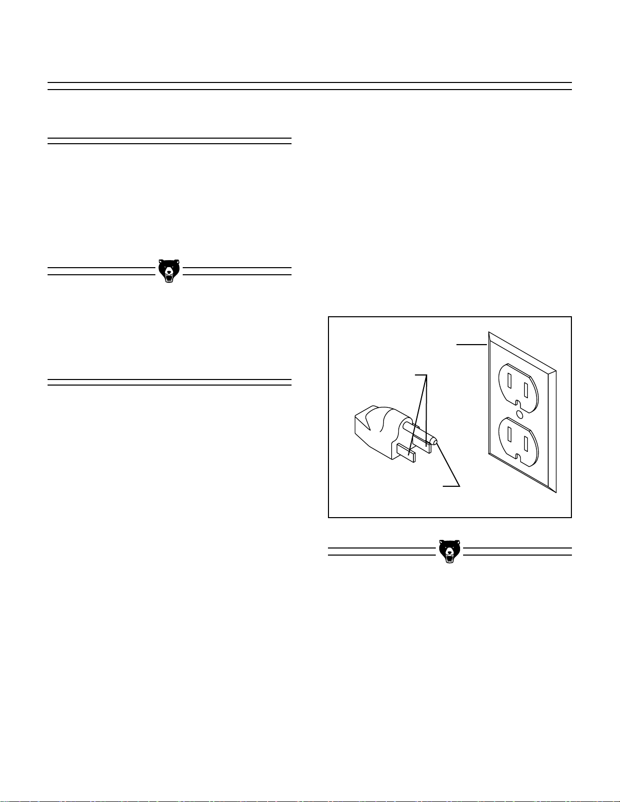
Figure 1.
Under no circumstances should the grounding
pin from any three-pronged plug be removed. If it
will not fit the outlet, have the proper outlet
installed by a qualified electrician.
Check with a qualified electrician or one of our
service personnel if the grounding instructions
are not completely understood, or if in doubt as to
whether the tool is properly grounded. Use only
3-wire extension cords that have 3-prong grounding type plugs and 3-hole receptacles that accept
the tool’s plug. FIgure 1.
Repair or replace damaged or worn cord immediately.
110V Operation
The 11⁄
2 H.P. motor will safely draw 16 amps at
110V. If you operate this sander on any circuit
that is already close to its capacity, it might blow
a fuse or trip a circuit breaker. However, if an
unusual load does not exist, and power failure still
occurs, have the circuit inspected by a qualified
electrician.
Grounding
CAUTION: THIS TOOL MUST BE GROUNDED
WHILE IN USE TO PROTECT THE OPERATOR
FROM ELECTRIC SHOCK.
In the event of a malfunction or breakdown,
grounding provides a path of least resistance for
electric current to reduce the risk of electric
shock. This tool is equipped with an electric cord
having an equipment-grounding conductor and a
grounding plug. The plug must be plugged into a
matching outlet that is properly installed and
grounded in accordance with all local codes and
ordinances.
Improper connections of the electrical-grounding
conductor can result in risk of electric shock. The
conductor with green or green and yellow striped
insulation is the electrical-grounding conductor. If
repair or replacement of the electric cord or plug
is necessary, do not connect the equipment
grounding conductor to a live terminal.
SECTION 2: CIRCUIT REQUIREMENTS
Grounded Outlet Box
Current
Carrying
Prongs
Grounding Blade Is
Longest Of the Three Blades
Page 7

G5049Z Combination Sander -5-
We are proud to bring you the Model G5049Z
Combination Sander. The Model G5049Z is part
of a growing Grizzly family of fine woodworking
machinery. When used according to the guidelines set forth in this manual, you can expect
years of trouble-free, enjoyable operation and
proof of Grizzly’s commitment to customer satisfaction.
The Model G5049Z is a combination 6" x 48" belt
and 12" disc sander that is capable of a wide variety of operations. The 6" wide belt enables you to
sand large areas flat very quickly, and the 12"
disc and table allow sanding at many different
angles. The G5049Z comes complete with stand,
miter gauge, motor and electrical package.
We are also pleased to provide this instruction
manual with the Model G5049Z Combination
Sander. This instruction manual was written to
guide you through assembly, review safety considerations and cover general operating procedures. It represents our latest effort to produce
the best documentation possible. If you have any
constructive criticisms or comments that you feel
we should include in our next printing, please
write to us at the Bellingham, WA address at the
end of this section.
SECTION 3: GENERAL INFORMATION
Most important, we stand behind our machines.
We have excellent regional service departments
at your disposal should the need arise. If you
have any service questions or parts requests,
please call or write to us at the location listed
below.
Grizzly Industrial, Inc.
1203 Lycoming Mall Circle
Muncy, PA 17756
Phone:(570) 546-9663
Fax:(800) 438-5901
E-Mail: techsupport@grizzly.com
Web Site: http://www.grizzly.com
To comment on this manual write to:
Grizzly Industrial, Inc.
C
⁄O Technical Documentation
P.O. Box 2069
Bellingham, WA 98227
To operate this, or any other power tool safely
and efficiently, it is essential to become as familiar with it as possible. The time you invest before
you begin to use your Model G5049Z will be time
well spent. DO NOT operate this machine until
you are familiar with the contents of this manual.
Page 8

-6- G5049Z Combination Sander
Contents of the Bolt Bag
QTY. DESCRIPTION
LOCATION
16
5
⁄16''-18 x 1⁄2'' Carriage Bolts
Stand
16
5
⁄16'' Flat Washers
Stand
16
5
⁄16''-18 Hex Nuts
Stand
4
5
⁄16''-18 x 1'' Hex Bolts
Stand /Feet
8
5
⁄16'' Flat Washers
Stand /Feet
4
5
⁄16''-18 Hex Nuts
Stand /Feet
In the event that any non-proprietary parts are
missing (e.g. a nut or a washer...), we would be
glad to replace them, or, for the sake of expediency, replacements can be obtained at your local
hardware store.
Unpacking
The Model G5049Z Sander is shipped from the
manufacturer in a carefully packed carton. If you
discover the machine is damaged after you’ve
signed for delivery, please call our Customer
Service number immediately for advice.
Save the containers and all packing materials for
possible inspection by the carrier or its agent.
Otherwise filing a freight claim can be difficult.
Caution: The G5049Z is a heavy machine (120
lbs. shipping weight). DO NOT over-exert your-
self while unpacking or moving your machine –
get assistance. In the event that your Sander
must be moved up or down a flight of stairs, be
sure that the stairs are capable of supporting the
combined weight of people and the machine.
When you are completely satisfied with the condition of your shipment, you should inventory its
parts.
Piece Inventory
After all the parts have been removed from the
container, you should have:
1 Sanding Unit
1 Sanding Belt
1 Sanding Disc
1 Idler Roller
1Miter Gauge
1Work Table
1 Belt Table
4 Stand Legs
4 Lower Stand Braces
4Rubber Feet
1 Quick Release Handle
1 Idler Roller Guard
1 Bolt Bag
1 Motor Mount
Page 9

G5049Z Combination Sander -7-
Clean up
The work table and other unpainted parts of the
Model G5049Z are coated with a waxy oil that
protects them from corrosion during shipment.
Remove the protective coating with mineral spirits and cloth rags. Do not use gasoline or other
petroleum based solvents because of their
extremely low flash points. Do not use chlorinebased solvents – if you happen to splash some
onto a painted surface, you’ll ruin the finish.
WARNING!
Follow the safety rules listed below when
working with solvents:
1. Read and follow all directions and warnings
on the solvent label.
2. Work only in a well ventilated area.
3. Do not work near any type of open flame
(e.g., pilot lights, kerosene heaters, and so
on).
4. DO NOT smoke while working with flamma-
ble material.
5. Paper towels and rags from the cleaning
process are extremely combustible. Dispose
of waste towels so they do not create a fire
hazard.
Site Considerations
1. Floor Load: Your G5049Z Sander repre-
sents a medium weight load in a small footprint. Most commercial floors are suitable for
the Model G5049Z. Some residential floors
may require additional build up to support
both machine and operator.
2. Working Clearances: Consider existing and
anticipated needs, size of material to be
processed through each machine, and
space for auxiliary stands, work tables or
other machinery when establishing a location for your sander.
3. Lighting and Outlets: Lighting should be
bright enough to eliminate shadow and prevent eye strain. Electrical circuits should be
dedicated or large enough to handle amperage requirements. Outlets should be located
near each machine so power or extension
cords are clear of high-traffic areas. Observe
local electrical codes for proper installation
of new lighting, outlets, or circuits.
Page 10

-8- G5049Z Combination Sander
SECTION 4: ASSEMBLY
Figure 2.
Figure 4.
Figure 3.
Stand/motor
2. Carefully tip the sander on its side and attach
the four legs to the stand top and the cross
braces to the legs.
3. Lift the sander upright and remove the
cover. Figure 3.
4. Attach the motor mount to the underside of
the stand. Finger tighten only. Figure 4.
The G5049Z Combination Sander stand is an
open frame style.
Note: Assembling the G5049 Sander requires
heavy lifting. We strongly recommend having an
assistant help with the assembly.
1. Attach Rubber Feet to base using the four
5
⁄16''-18 x 1'' Hex bolts, Hex Nuts and Flat
Washers provided. Figure 2.
Page 11

G5049Z Combination Sander -9-
Figure 5.
Figure 6.
10. Re-install the cover.
5. Mount the motor to the motor mount. Leave
the bolts finger tight for now.
6. Lift the spring loaded side of the jackshaft
assembly up and insert a
1
⁄16'' shim between
the cast bearing block and the aluminum
pad.
7. Lift the motor up and slip the two flat bars
between the stand top and the motor drive
disc. Let the weight of the motor rest on the
flat bars. Tighten down the motor mount
bolts.
8. Remove the two flat bars and the shim
fromthe jack shaft assembly.
9. Align the center of the motor drive disc to the
centerline of the jack shaft. Figure 5. Tighten
the motor mount bolts.
Wiring The Motor
1. Remove the wire box cover.
2. Feed the power source wires from the switch
into the motor junction box.
3. Wire the motor per the diagram in Figure 6.
The wires from the power supply, besides
the Green Ground wire, are interchangable,
therefore colors are not specified.
4. The green wire from the cord is grounded to
the motor casing.
5. Re-install the wire box cover.
Note: To reverse rotation, switch the positions of
motor wires #5 and #6.
Drive disc
Jackshaft
C/L
Align the center of the drive disc
to the centerline of the jack shaft
Page 12

-10- G5049Z Combination Sander
2. Turn the knob approximately
1
⁄4 turn clockwise to move the belt towards the tracking
knob, counter-clockwise to move the belt
away.
3. Turn the machine on and off again quickly to
see if the tracking has improved. If not,
repeat step 1. If tracking is improved move
to step 4.
4. Now with the sander running, adjust the
knob to fine tune the belt tracking.
Belt Replacement
SECTION 5: ADJUSTMENTS
With the exception of Belt Tracking, adjustments
to your Combination Sander should be made with
the power off and the machine unplugged.
Unlock the Quick-Release Lever by pulling the
lever straight out. Figure 7. Slide the belt off the
rollers straight toward you. Reverse this process
to install a new belt.
Figure 7.
Belt Tracking
The goal of this procedure is to achieve proper
belt tracking that prevents the belt from wandering off to either side.
1. To adjust the tracking, quickly turn the
sander on and off. Observe the belt’s behavior. If the belt moves to one side or the other,
you will need to adjust the tracking knob.
Figure 8.
Figure 8.
Page 13

G5049Z Combination Sander -11-
3. Tighten hex bolt and run the sander to adjust
the tracking if necessary.
4. Try aggressively sanding a piece of scrap
wood. If the tracking is not significantly
affected and the belt does not slip on the
drum, your belt tension is correct.
Belt Tensioning
Correct belt tension will insure that your sander
functions properly. Too little tension will allow the
belt to slip and may cause the sander to track
erratically. Too much will cause the drive drum to
creep on the drive shaft and possibly cause premature bearing failure. It is impossible to describe
ideal belt tension. A good rule of thumb is less
tension is better than too much. If the belt sounds
like a drum when plucked, your tension is probably set too tight. If your belt does not track and
slips under load, it is too loose. Use the following
steps to adjust tension.
1. With belt installed and quick release lever
engaged, loosen Hex Bolt slightly. Figure 9.
Note: Figure 9 is depicted with the belt
removed for illustration purposes only.
Normally steps 1-4 are done with the belt
installed.
Figure 9.
2. Use a large open end adjustable wrench and
carefully rotate the eccentric to increase or
decrease tension. Remember: The belt
should not sound like a drum when plucked.
If it does, decrease the tension. Figure 10.
Figure 10.
Page 14

-12- G5049Z Combination Sander
Horizontal Sanding
1. Turn the sander on and allow the belt to
reach full speed.
2. Place the workpiece flat on the belt. Be sure
to hold the work securely with both hands.
Place one hand at the end of the workpiece
to feed it against the rotation of the belt, and
one hand lightly on top of the piece to ensure
adequate stock removal. Figure 11.
3. Depending on the length of the workpiece,
use the back stop to prevent it from being
ejected by the belt. If your workpiece is too
long, simply remove the back stop.
Figure 11.
SECTION 6: OPERATIONS
Once assembly is complete and adjustments are
done to your satisfaction, you are ready to test
the machine.
Turn on the power supply at the main panel.
Press the START button. Make sure that your finger is poised on the STOP button, just in case
there’s a problem. The sander should run
smoothly, with little or no vibration or rubbing
noises. Strange or unnatural noises should be
investigated and corrected before operating the
machine further.
WARNING: DO NOT attempt to investigate or
adjust the machine while it is running. Wait until
the machine is turned off, unplugged and all
working parts have come to a rest before you do
anything!
If noises occur that cannot be found by visual
inspection, feel free to contact our service department for help.
Test Run
Page 15

G5049Z Combination Sander -13-
Curved Sanding
To sand curves, use the end of the belt arm. Hold
the workpiece firmly and apply light, even pressure to the belt. To avoid excessive loading of the
belt in one area, move workpiece slowly across
entire surface of belt. Figure 12.
Figure 12.
Disc Sanding
1. Loosen table lock knob and tilt work table to
desired angle. Tighten lock knob.
2. Ease workpiece into the half of the disc that
spins down toward the table. Figure 13.
3. When using the table for beveled sanding
operations, smaller workpieces are at risk of
getting jammed between the disc (or vertical
belt) and the table. Figure 14.
Figure 13.
Figure 14.
Page 16

-14- G5049Z Combination Sander
SECTION 7: MAINTENANCE
Lubrication
V- Belt
Your combination sander is equipped with shielded and pre-lubricated ball bearings and require
no lubrication for the life of the bearings. All bearings are common sizes and are readily available
from a local bearing supply house or our Service
Department.
Without proper belt tension and correct pulley
alignment, your sander will vibrate excessively
and wear out the V-belt and the bearings much
faster than normal. The pulleys can be aligned by
placing a straightedge along the outside flanges
and sighting down the straightedge. Move one
pulley along the shaft until both pulleys are in line.
Proper belt tension can be checked by squeezing
the midpoint of the belt with moderate pressure
(about 5 pounds). The resulting deflection should
be about
1
/4". If it isn’t, it will be necessary to
loosen the motor mount bolts and slide the motor
to either add or subtract tension from the belt.
Make a habit of inspecting your sander each time
you use it. Check for the following conditions and
repair or replace when necessary.
1. Loose mounting bolts.
2. Worn switch.
3. Worn or damaged cords and plugs.
4. Worn or damaged V-belt.
5. Poor belt tensioning/tracking.
General
Table
The working table and other non-painted surfaces on the Model G5049Z should be protected
against rust and pitting. Wiping the sander clean
after every use ensures that sawdust isn’t
allowed to trap moisture against bare metal surfaces.
Some woodworkers recommend using automotive paste wax on exposed steel and cast iron
surfaces. The wax provides a layer of protection,
as well as reducing friction between lumber and
the table. Avoid waxes that contain silicone or
other synthetic ingredients. These materials can
find their way into lumber that’s being sanded and
can make staining and finishing difficult. If you
use paste wax, make sure that it’s 100%
Carnauba wax.
Page 17

G5049Z Combination Sander -15-
The following pages contain general machine
specifications, parts diagram and list and
Warranty/Return information for your Model
G5049Z Combination Sander.
If you need parts or help in assembling your
machine, or if you need operational information,
we encourage you to call our Service
Department. Our trained service technicians will
be glad to help you.
If you have comments or concerns dealing specifically with this manual, please write to our
Bellingham, Washington location using the
address in the Introduction. The specifications,
drawings, and photographs illustrated in this
manual represent the Model G5049Z as supplied
when the manual was prepared. However, due to
Grizzly’s policy of continuous improvement,
changes may be made at any time with no obligation on the part of Grizzly. Whenever possible,
though, we send manual updates to all owners of
a particular tool or machine. Should you receive
one, add the new information to this manual and
keep it for reference.
The information in this manual has been obtained
from sources we believe to be reliable and as upto-date as possible. We have included some
important safety measures which are essential to
this machine’s operation. While most safety measures are generally universal, Grizzly reminds
you that each workshop is different and safety
rules should be considered as they apply to your
specific situation.
We recommend you keep a copy of our current
catalog for complete information regarding
Grizzly's warranty and return policy. If you need
additional technical information relating to this
machine, or if you need general assistance or
replacement parts, please contact the Service
Department listed in the introduction.
Additional information sources are necessary to
realize the full potential of this machine. Trade
journals, woodworking magazines, and your local
library are good places to start.
WARNING!
Like all power tools, there is danger associated
with the Model G5049Z Combination Sander.
Use the tool with respect and caution to lessen
the possibility of mechanical damage or operator
injury. If normal safety precautions are overlooked or ignored, injury to the operator or others
in the area is likely.
The Model G5049Z was specifically designed for
sanding operations. DO NOT MODIFY AND/OR
USE THIS SANDER FOR ANY OTHER PURPOSE. Modifications or improper use of this
tool will void the warranty. If you are confused
about any aspect of this machine, DO NOT use it
until all your questions have been answered.
SECTION 8: CLOSURE
Page 18

-16- G5049Z Combination Sander
Page 19

G5049Z Combination Sander -17-
Page 20

-18- G5049Z Combination Sander
Page 21

G5049Z Combination Sander -19-
Page 22

-20- G5049Z Combination Sander
Page 23

G5049Z Combination Sander -21-
REF PART # DESCRIPTION REF PART # DESCRIPTION
36 P5049036 SCALE
37 P5049037 STOP BAR
38 P5049038 SPACER
39 P5049039 BRACE, SHORT
40 P5049040 BRACE, LONG
41 P5049041 STEEL BLOCK
42 P5049042 CENTER PIN
43 P5049043 SPECIAL SETSCREW
44 P5049044 HEX BOLT
45 P5049045 FLAT WASHER
46 P5049046 LOCK WASHER
47 P5049047 CAP SCREW
48 P5049048 CAP SCREW
49 P5049049 ROLL PIN
50 P5049050 ROLL PIN
51 P5049051 MOTOR CORD
52 P5049052 KEY
53 P5049053 SCREW
54 P5049054 ROLL PIN
55 P5049055 FLAT HEAD SCREW
56 P5049056 SCREW
57 P5049057 HEX BOLT
58 P5049058 DIRECTION ARROW
59 P5049059 WASHER
60 P5049060 KNOB
61 P5049061 GUARD
62 P5049062 V-BELT
63 P5049063 KNOB
64 P5049064 KNOB
65 P5049065 ON / OFF SWITCH
66 P5049066 POWER CORD
67 P5049067 GRAPHITE PAD
68 P5049068 CAP SCREW
69 P5049069 HEX BOLT
70 P5049070 HEX NUT
01 P5049001 MAIN BODY
02 P5049002 TRUNNION,LEFT
03 P5049003 TRUNNION,RIGHT
04 P5049004 DISC TABLE
05 P5049005 BRACKET HOUSING
06 P5049006 STOP BLOCK
07 P5049007 BELT TABLE
08 P5049008 CAST IRON DISC
09 P5049009 LOWER GUARD
10 P5049010 UPPER GUARD
11 P5049011 STAND, TOP
12 P5049012 MOUNTING BRACKET
13 P5049013 COVER, LOWER
14 P5049014 COVER
15 P5049015 COVER, UPPER
16 P5049016 BELT FRAME
17 P5049017 SPACER
18 P5049018 POINTER
19 P5049019 GIB
20 P5049020 KNOB
21 P5049021 WASHER
22 P5049022 MITER BODY
23 P5049023 SCREW
24 P5049024 POINTER
25 P5049025 MITER BODY
26 P5049026 12'' SANDING DISC
27 SEE CAT 6'' X 48'' SANDING BELT
28 P5049028 CARRIAGE BOLT
29 P5049029 WASHER
30 P5049030 HEX NUT
31 P5049031 FOOT
32 P5049032 BOLT
33 P5049033 LEG
34 P5049034 DRIVE SHAFT
35 P5049035 SCALE
Page 24

-22- G5049Z Combination Sander
REF PART # DESCRIPTION
71 P5049071 WASHER
72 P5049072 STRAIN RELIEF
73 P5049073 DUST COVER
74 P5049074 SNAP RING
75 P5049075 BEARING
76 P5049076 SNAP RING
77 P5049077 SPACER
78 P5049078 DRIVE DRUM
79 P5049079 SETSCREW
80 P5049080 BEARING
81 P5049081 SNAP RING
82 P5049082 IDLER DRUM
83 P5049083 IDLER SHAFT
84 P5049084 SLIDING BAR
85 P5049085 ROCKER PLATE
86 P5049086 LOCK WASHER
87 P5049087 CAP SCREW
88 P5049088 FENDER WASHER
89 P5049089 HEX BOLT
90 P5049090 HEX BOLT
91 P5049091 WASHER
92 P5049092 ECCENTRIC
93 P5049093 SPACER
94 P5049094 ROCKER ARM
95 P5049095 HEX NUT
96 P5049096 LEVER, SHORT
97 P5049097 LEVER, LONG
98 P5049098 KNOB
99 P5049099 JAM NUT
100 P5049100 KNOB
101 P5049101 PULLEY
102 P5049102 BRACKET
103 P5049103 BEARING BLOCK
104 P5049104 JACK SHAFT
105 P5049105 DRIVE DISC
106 P5049106 TIRE
107 P5049107 BLOCK
REF PART # DESCRIPTION
108 P5049108 CAP SCREW
109 P5049109 SPRING
110 P5049110 LOCK WASHER
111 P5049111 MOTOR
112 P5049112 MOUNTING BLOCK
113 P5049113 ARM
114 P5049114 THREADED SHAFT
115 P5049115 STUD
116 P5049116 BRACKET
117 P5049117 HEX BOLT
118 P5049118 WHEEL
119 P5049119 HUB, LEFT
120 P5049120 HUB, RIGHT
121 P5049121 SPECIAL NUT
122 P5049122 MOTOR BRACKET
123 P5049123 SCALE
124 P5049124 RIVET
125 P5049125 KEY
126 P5049126 SNAP RING
127 P5049127 HEX BOLT
128 P5049128 LOCK WASHER
129 P5049129 CAP SCREW
130 P5049130 KNOB
131 P5049131 SETSCREW
132 P5049132 SETSCREW
133 P5049133 SCREW
134 P5049134 HEX NUT
135 P5049135 ALLEN WRENCH
136 P5049136 CAP SCREW
137 P5049137 ROUND THING
138 P5049138 WASHER
139 P5049139 JAM NUT
142 P5049142 CHART
143 P5049143 POINTER
144 P5049144 SETSCREW
145 P5049145 WASHER
Page 25

G5049Z Combination Sander -23-
Machine Data
GRIZZLY MODEL G5049Z COMBINATION SANDER
Design Type .......................................................................................................................... Floor Model
Overall Dimensions and Specifications:
Base ........................................................................................................................20 x 27
3
⁄4""
Height (Belt arm horizontal) ............................................................................................40
1
⁄2"
Height (Belt arm vertical)..................................................................................................55
1
⁄2"
Width ....................................................................................................................................30"
Length ..................................................................................................................................29"
Table (Disc) ................................................................................................................13" x 14"
Motor Shaft Size....................................................................................................................
5
⁄8"
Weight ..........................................................................................................................200 lbs.
Features:
Sanding Belt..................................................................................................................6" x 48"
Sanding Belt Speed ..........................................................................................Variable Speed
Cast Iron Disc ......................................................................................................12" Diameter
Cast Iron Disc Speed ..............................................................................................3450 RPM
Roller Drive ............................................................................................................Ball Bearing
Miter Gauge Groove......................................................................................................
3
⁄8" x 3⁄4"
Miter Gauge ......................................................................Die Cast Aluminum / Aluminum Bar
Table Tilt Range................................................................................................................0-45°
Construction:
Base ..................................................................................................................Steel/Cast Iron
Table (Disc) ................................................................................................................Cast Iron
Stand..................................................................................................................Stamped Steel
Motor:
Horsepower ....................................................................................................................1
1
⁄2 HP
Phase Type / Voltage......................................................................Single Phase / 110V/220V
Amperage ................................................................................................16@110V / 8@120V
Cycle and RPM........................................................................................60 Hertz / 3450 RPM
Switch ..............................................................................................................On / Off Toggle
Power Transfer ..........................................................................................................Belt Drive
Bearings ................................................................................Sealed, Permanently Lubricated
Specifications, while accurate, are subject to change without notice.
Page 26

-24- G5049Z Combination Sander
Grizzly Industrial, Inc. warrants every product it sells for a period of 1 year to the original purchaser from
the date of purchase. This warranty does not apply to defects due directly or indirectly to misuse, abuse,
negligence, accidents, repairs or alterations or lack of maintenance. This is Grizzly’s sole written warranty
and any and all warranties that may be implied by law, including any merchantability or fitness, for any particular purpose, are hereby limited to the duration of this written warranty. We do not warrant or represent
that the merchandise complies with the provisions of any law or acts unless the manufacturer so warrants.
In no event shall Grizzly’s liability under this warranty exceed the purchase price paid for the product and
any legal actions brought against Grizzly shall be tried in the State of Washington, County of Whatcom.
We shall in no event be liable for death, injuries to persons or property or for incidental, contingent, special, or consequential damages arising from the use of our products.
To take advantage of this warranty, contact us by mail or phone and give us all the details. We will then
issue you a “Return Number’’, which must be clearly posted on the outside as well as the inside of the carton. We will not accept any item back without this number. Proof of purchase must accompany the merchandise.
The manufacturers reserve the right to change specifications at any time because they constantly strive to
achieve better quality equipment. We make every effort to ensure that our products meet high quality and
durability standards and we hope you never need to use this warranty.
Please feel free to write or call us if you have any questions about the machine or the manual.
Thank you again for your business and continued support. We hope to serve you again soon.
WARRANTY AND RETURNS
 Loading...