


1
410 000
GRIZZLY
OPERATOR’S INSTRUCTION MANUAL
MODEL: ____________________ ENGINE MODEL: _______________
SERIAL: _____________________ ENGINE SERIAL: _______________
DATE OF PURCHASE: ____________
PURCHASED FROM: __________________________
WARNING: THIS PRODUCT IS DESIGNED AND MANUFACTURED TO
PROVIDE SAFE AND DEPENDABLE SERVICE IF OPERATED
ACCORDING TO INSTRUCTIONS. THE MANUFACTURER
PROVIDES THE FOLLOWING INSTRUCTIONS FOR USE AND
CARE OF THIS EQUIPMENT AND RELIES UPON THE
PURCHASER TO SEE TO IT THAT THESE INSTRUCTIONS ARE
MADE CLEAR TO THE PERSONS WHO WILL ACTUALLY BE
USING THE EQUIPMENT. FAILURE TO DO SO COULD RESULT
IN SERIOUS INJURY OR EQUIPMENT DAMAGE.
©Alcor 2011 All rights reserved
GRIZZLY EQUIPMENT
9475 PASCAL GAGNON STREET, ST-LÉONARD, QUEBEC, CANADA
TEL: (514) 325-1260 / 1-888-325-9953 FAX: (514) 325-9952
E-MAIL: info@alcor-inc.com Web site: www.grizzlyequip.com

INDEX
INTRODUCTION ....................................................................................................................................................................................................................... 3
PREPARATION ......................................................................................................................................................................................................................... 4
OPERATOR;......................................................................................................................................................................................................................... 4
WEAR PROPER ATTIRE ............................................................................................................................................................................................................ 4
ROOF PREPARATION (IF G41 IS TO BE USED BY ROOFERS) .......................................................................................................................................... 4
INSPECT ROOF DECK .......................................................................................................................................................................................................... 4
WARNING LINE SYSTEM ..................................................................................................................................................................................................... 4
HOISTING MACHINE TO ROOF ................................................................................................................................................................................................ 4
CONNECTING TO LIFT RINGS .............................................................................................................................................................................................. 4
SAFETY PRECAUTIONS ............................................................................................................................................................................................................. 5
SAFETY PRECAUTIONS WHEN WORKING ON A ROOF ............................................................................................................................................................. 5
KNOWING THE G41 ................................................................................................................................................................................................................. 6
SPECIFICATIONS ...................................................................................................................................................................................................................... 6
THE CONTROLS ....................................................................................................................................................................................................................... 7
ATTACHMENT PLATE AND CONNECTORS ............................................................................................................................................................................... 8
WORKING AREA ...................................................................................................................................................................................................................... 8
OPERATING PRECAUTIONS ..................................................................................................................................................................................................... 8
OPERATING THE G41............................................................................................................................................................................................................... 9
START UP PROCEDURE ....................................................................................................................................................................................................... 9
SHUT DOWN PROCEDURE .................................................................................................................................................................................................. 9
MOUNTING ATTACHMENTS ............................................................................................................................................................................................. 10
RELEASING ATTACHMENTS .............................................................................................................................................................................................. 10
OPERATING THE STANDARD BUCKET ............................................................................................................................................................................... 10
LOUVERS .......................................................................................................................................................................................................................... 10
MAINTENANCE ...................................................................................................................................................................................................................... 11
MAINTENANCE CHART ..................................................................................................................................................................................................... 11
ENGINE OIL CHECK ........................................................................................................................................................................................................... 12
ENGINE OIL AND FILTER CHANGE .................................................................................................................................................................................... 12
ENGINE AIR FILTER ........................................................................................................................................................................................................... 12
FUEL FILTER ...................................................................................................................................................................................................................... 12
REFUELING ....................................................................................................................................................................................................................... 12
SPARK ARRESTOR (MUFFLER) .......................................................................................................................................................................................... 12
BATTERY ........................................................................................................................................................................................................................... 12
CHECK BATTERY/TERMINALS ........................................................................................................................................................................................... 13
HYDRAULIC OIL LEVEL ...................................................................................................................................................................................................... 13
HYDRAULIC OIL CHANGE .................................................................................................................................................................................................. 14
CHECK HYDRAULIC HOSES ................................................................................................................................................................................................ 14
GREASE(LUBRICATION) .................................................................................................................................................................................................... 15
TIRE PRESSURE ................................................................................................................................................................................................................. 15
2
©Alcor 2011 All rights reserved

INTRODUCTION
410000 G41 MINI LOADER
Thank you for purchasing this quality GRIZZLY product. With proper use and care, the G41 will provide many years of
reliable service. For the safety of all job-site personnel it is mandatory that the instructions provided for the use and handling
of the equipment be read and thoroughly understood by the operators.
CAUTION
INTENDED USE; THIS MACHINE IS INTENDED TO BE USED ON FLAT, LEVEL GROUNDS. ABUSE AND OR
MODIFICATION OF THIS EQUIPMENT VOIDS THE MANUFACTURER’S WARRANTY AND IS THE SOLE
RESPONSIBILITY OF THE OWNER/USER, SHOULD ANY DAMAGE OR INJURY OCCUR.
3
©Alcor 2011 All rights reserved
4
Fig. 1
Fig. 2
PREPARATION
OPERATOR;
START BY READING AND FULLY UNDERSTANDING OPERATING INSTRUCTIONS. IF SOMETHING IS NOT
UNDERSTOOD, HAVE SOMEONE ELSE READ AND EXPLAIN THE INSTRUCTIONS TO THE OPERATOR OR
CALL THE MANUFACTURER FOR INFORMATION. AN UNINFORMED OPERATOR CAN SUBJECT HIMSELF
AND OTHERS TO DEATH OR SERIOUS INJURY.
WEAR PROPER ATTIRE
Safety glasses are recommended and must be worn if any roof cutting or scraping is being done in the vicinity. Safety
glasses and or face shield are also necessary when working with hot stuff.
Wear properly fitting clothes. Tight clothing can restrict movement and slow down reaction time in a dangerous situation.
Loose fitting clothing can be dangerous and cause serious injury if it gets caught in moving mechanical parts. Wear a
long-sleeved shirt, buttoned at the cuffs, safety shoes, and pants without cuffs, and knit wrist type gloves.
A hard hat must be worn by operator when working on a job site.
ROOF PREPARATION (IF G41 IS TO BE USED BY ROOFERS)
INSPECT ROOF DECK
Before allowing equipment and personnel access to roof, make certain roof is strong enough to support the weight. Check
load limits of deck with owner, builder or architect. Clear the work area of all potentially dangerous obstacles that could
cause personal injury to the operator or others. Keep unauthorized people away from construction area. Check to see that
all roof openings are guarded to protect against falls.
WARNING LINE SYSTEM
The operation of this piece of equipment must be in compliance with Federal OSHA standards governing safety
perimeters with respect to the use of power equipment. When operating parallel to roof edge warning line system must
be at least six feet from edge. When operating perpendicular to edge warning line must be ten feet from roof edge. For
specific information on warning lines, the use of guard rails and motion-stopping safety systems, refer to section on
OSHA Law.
HOISTING MACHINE TO ROOF
WARNING; ALWAYS CHECK DECK LOAD LIMITS WITH BUILDER, OWNER, OR ARCHITECT
BEFORE DECIDING TO USE ON THE ROOF.
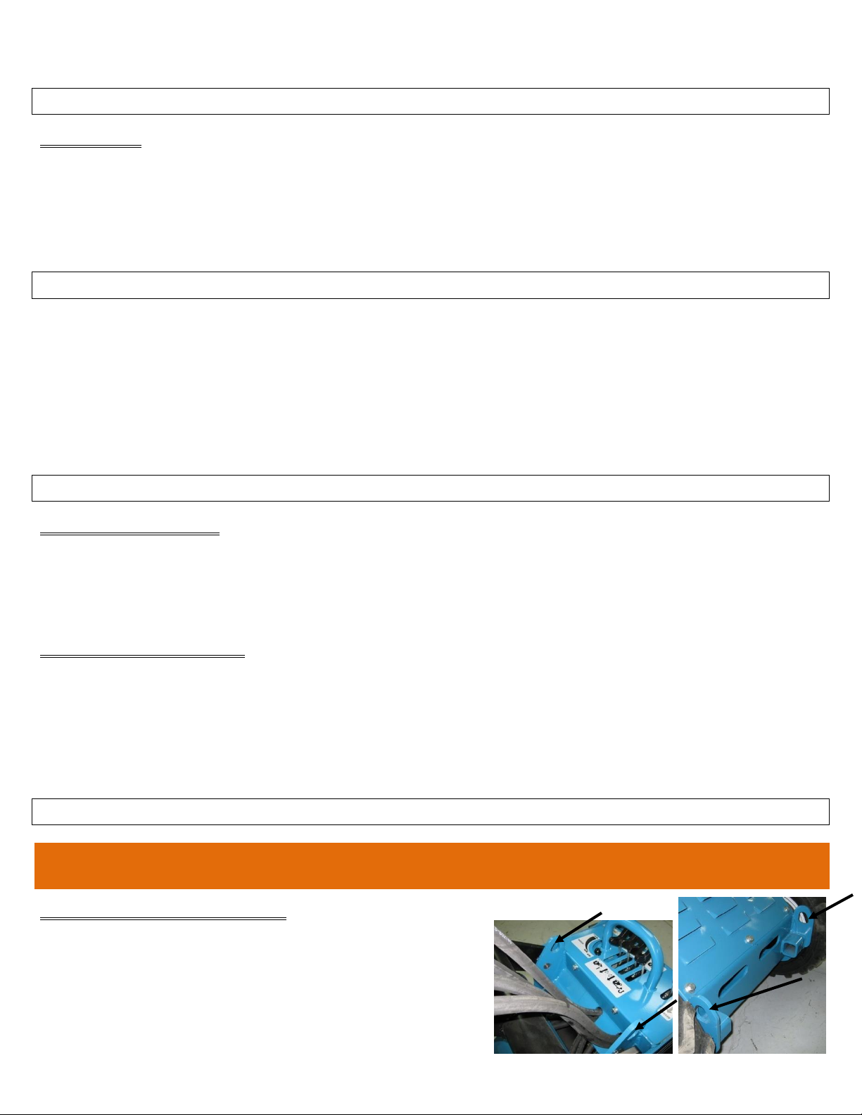
CONNECTING TO LIFT RINGS
Four hoist rings are provided on the G41 as shown in Fig. 1 and 2.
WEIGHT;
Model: 410000 1190 LBS
410100 120 LBS
©Alcor 2011 All rights reserved

SAFETY PRECAUTIONS
Only qualified, authorized adults should be allowed to operate this machine.
Read and understand all manuals and instructions before operating and servicing.
Inspect work area for holes, drop-offs or unstable ground. Know the weight limitation of operating surfaces and
clearances.
Make certain all controls and levers are in the neutral or “OFF” position before starting engine (Fig. #3, #5 and #6).
Operate the controls smoothly, do not make brisk movements.
Never back up without looking behind you.
Always bring the accessory flow lever to the “OFF” position before engaging or disengaging the accessory lever.
Then increase flow as desired. (Fig. 3, #6)
Do not allow people near the machine during operation.
Never carry or transport people in any circumstances.
Never operate a machine that is damaged in any way. Repairs or replacement of damaged components must be made
by a qualified mechanic.
Do not modify this machine. Do not operate a modified machine.
Wear safety footwear, eye and ear protection and snug fit clothing.
Operate the G41 only from the operator’s platform.
Always shut down G41 as in the “shut down procedure” before stepping down from the operator platform.
Always chock wheels when parking machine on a slope.
Always wear protective gear when operating and servicing this machine, machine will be hot and escaping oil can
burn and or penetrate skin.
Relieve hydraulic pressure before servicing hydraulics or using quick connectors.
Make certain all pins and bolts are used and secure.
Always use the cylinder lock if maintenance is required under the loader arms and or you want to keep the loader
arms up without being on the operator platform. (Fig. 10)
Never allow the G41 to be left alone with the engine running and or with the loader arms up if the cylinder lock is not
in place. (Fig. 10)
Keep children and pets at a safe distance at all times.
Keep hands, fingers and feet from moving parts at all times.
Operate the G41 on flat level ground as much as possible.
Stay alert and aware of your surroundings and stop operations if someone wanders to close to the machine.
Most parts of the G41 will be very hot while machine is in operation and after, keep from touching any hot part of it
and wear gloves.
Do not operate this machine if you are under the influence of alcohol, marijuana, or drugs that could impair your
judgment and ability.
Use extreme caution when handling fuel. Gasoline is very flammable. Shut off engine, allow to cool before
re-fuelling. Clean up spilled gasoline before restarting. (Fig. 12)
Never carry objects that may restrict or obstruct your vision.
On slopes, keep heavy end of loader uphill. (See operating precautions)
Travel up or down, never across slopes.
5
SAFETY PRECAUTIONS WHEN WORKING ON A ROOF
Please follow all previous precautions plus the following.
Check load limits of the deck with owner, contractor or architect before attempting to use the G41 on a roof.
Guard all openings on the roof.
Do not operate within 10 feet of roof edge (or within 6 feet, if operation is parallel to the edge).
Make certain OSHA requirements for safety equipment and handling of material are satisfied.
©Alcor 2011 All rights reserved

6
KNOWING THE G41
The G41 has 4 hydraulic wheel motors that allow forward, reverse and turning without relying on chains that stretch and can
break. These motors are controlled by two levers. Two control levers are also provided for lift of the loader arms and tilt of
the attachment plate. The control levers are sensitive and require some practice to enjoy the manoeuvrability they will
provide to the operator.
Attachments are controlled by the accessory control lever, this is a push to engage and pull to engage lever with detent. The
center position is the “OFF” position. This allows for clockwise and counter clockwise rotation of a hydraulic motor or in
and out of a hydraulic cylinder. (Keep from using the detent if operating an accessory with a cylinder).
The G41 also provides the ability to decide how much hydraulic oil flow the operator wants to direct to the accessory by
adjusting the flow control lever.
SPECIFICATIONS
Model: #410000
Engine: Kohler CH20S
Weight: 1190 lbs
Weight with bucket: 1310 lbs
Length: 66”
Length with bucket: 86”
Height: 52”
Width: 39”
Wheelbase: 32”
Clearance: 5.75”
Hinge pin height: 69.75”
Angle of departure: 22 deg.
Dump angle: (std bucket): 41 deg.
Rollback: 35
Reach at 41 deg. Dump: 23.75”
Operating capacity: 500 lbs
Tip load: 1000 lbs
Max. speed: 4 mph
Gasoline capacity: 8 gal.
Hydraulic oil capacity: 15 gal.
Hydraulic press. main valve: 2900 psi
Hydraulic press. accessory valve: 2500 psi
Hydraulic pumps 12 gal.
Wheels (std): 18 X 8.50-8
©Alcor 2011 All rights reserved

7
2
1
5
3
Fig. 3
DANGER: Never put this lever in its detent position before the loader arms are on the ground, otherwise they will fall
to the ground causing damage and or injury.
THE CONTROLS
1. Control lever for the left side travel motors
Pushing forward on this lever turns the left wheels forward
Pulling back on this lever turns the left wheels backward
2. Control lever for the right side travel motors
Pushing forward on this lever turns the right wheels forward
Pulling back on this lever turns the right wheels backward
3. Control lever for loader arms
Pulling on this lever lifts the loader arms
Pushing on this lever lowers the loader arms
If you push on this lever past its detent point it will lock and activate the float function which allows the loader arms to float
and allows the bucket or other attachments to follow the contours of the ground.
4. Control lever for the tilt function
Pushing on this lever tilts the attachment plate forward.
Pulling on this lever tilts the attachment plate backward.
5. Accessory control lever
This lever will direct oil flow to the accessory. The operator can either push or pull on the lever to send oil
flow to a hydraulic cylinder. Or if the accessory has a hydraulic motor, the lever can be set in its forward or
reverse detent position.
Make sure to bring the lever back to the “OFF” or center position to stop flow to the accessory and to relieve
pressure.
NOTE: The engine may be hard to turn over when starting if this control lever (#5) is left in a detent
position.
6. Flow control lever
This lever will provide more or less flow to the accessory valve allowing the operator to choose the flow at
which he wants to operate an attachment without having to lower or increase engine RPM.
It is also a good idea to reduce flow before engaging and disengaging the accessory lever to minimize shock to
the accessory motor.
NOTE: When an accessory is not being used, it is best to leave this lever (#6) in the “OFF” position.
©Alcor 2011 All rights reserved

Fig. 4
WARNING: RELIEVE TRAPPED PRESSURE IN THE HOSES BEFORE
ATTEMPTING TO CONNECT FLAT FACE COUPLERS OR COUPLERS
MAY FAIL.
The G41 features a universal attachment plate which allows the use of numerous
accessories such as buckets, sweepers, tear-off blades, augers, plows, forks, etc…
The G41 also features 2 flat face couplers, one male and one female to provide
hydraulic flow to the various accessories that may require it (Fig. 4).
CHECK WHEEL MOTOR WOODRUFF KEYS DAILY TO ENSURE THAT THE WHEEL HUB IS SOLIDLY ATTACHED TO THE WHEEL
MOTOR. USING THE MACHINE WITH A BROKEN WOODRUFF KEN WILL DAMAGE THE HUB AND WEEL MOTOR.
ATTACHMENT PLATE AND CONNECTORS
To relieve pressure, turn engine off, set flow control lever (#6 in Fig. 3) to OFF and
actuate accessory control lever (#5 in Fig. 3) forward and reverse to empty lines. Connect flat face couplers.
WORKING AREA
It is important that you first walk the area that you are going to work in with the G41.
- Look for loose or soft soil, wet, damp or muddy land, sandy or icy conditions are all potential hazards when operating
a mini loader.
- Holes, drop-offs, ditches, slippery surfaces, culverts, unstable surfaces, hillsides, large rocks, trees are all causes for
concern.
- Evaluate the situation before proceeding with the task at hand. Do not proceed if the hazards can not be corrected or
avoided.
- Make sure to have the area marked for buried lines.
- Consult local utility service providers (gas, electric, cable, water, telephone) before any digging is performed.
8
OPERATING PRECAUTIONS
- Start by planning your work
- Inspect the G41, check for leaks, broken or loose parts, check oil levels (hydraulic and engine), check and refill fuel
tank.
- Check wheel motor woodruff keys daily to ensure that the wheel hub is solidly attached to the wheel motor.
Using the machine with a broken woodruff key will damage the hub and wheel motor.
- Operate all controls smoothly and slowly and never stop abruptly, avoid brisk movements. This will make your work
safer and more comfortable.
- Always keep a firm grip on the handle bar as the machine moves to keep from loosing balance and injuring yourself.
- Always look in the direction you are going, turn and or reverse at a reduced speed. Do not make sharp turns at speed
and try to come to a stop smoothly.
- Stop operating the machine if someone wanders to close.
- Never exceed the rated capacity on the G41 and or its attachments. Understand that different attachments will change
the way the G41 acts and reacts.
- Travel with the bucket or attachment as close to the ground as possible, traveling with raised loader arms will make
the machine unstable.
- Try to avoid working on slopes, but if necessary use extreme caution and travel at lower speeds.
- Do not travel across slopes.
- Do not park on slopes.
- If you have to work on a slope, travel straight up or down making sure the heavy end of the machine is always
pointing up the slope.
- On an empty or unloaded machine the operator platform is the heavy end.
- On a loaded machine or with a heavy attachment, the front is the heavy end.
- Load, unload and turn on flat level ground. Do not travel or turn with loader arms up.
- Operate only from the operator’s platform; always keep hands on handle bar and controls.
- Keep the bucket level when raising loader arms to prevent material or debris from falling from bucket.
©Alcor 2011 All rights reserved

Fig. 5
Fig. 6
Fig. 7
OPERATING THE G41
START UP PROCEDURE
1) Walk around the machine to look for possible damage,
leaks, loose parts, etc. If any are found, have the
machine repaired immediately.
2) Check hydraulic and engine oil levels, check air filter
and fill gasoline tank if necessary, check tire pressure
and adjust. Grease all pivot points if necessary.
3) Make sure all control levers are in the neutral position,
check them by pushing and pulling them to see if they
come back to neutral on their own. Make sure the flow
control lever is in the “OFF” position and that the
accessory control lever is also in the “OFF” position.
4) To start the engine, stand on the operator’s platform, put the choke lever to the left or “ON” position, put the
throttle lever about half way and turn the ignition key, as soon as the engine starts, release the key. As soon
as the engine is warm enough, put the choke lever to the right or “OFF” position. Allow the machine to idle
for about 5 minutes to warm-up
9
NOTE; In cold weather, it will take longer to warm up. Operate all the main controls carefully to circulate
warm oil to the cylinders and wheel motors.
SHUT DOWN PROCEDURE
1) Park the machine on flat level ground.
2) Lower the loader arms or set the attachment down.
3) Make sure all control levers are in the neutral position. Make sure
the flow control lever is in the “OFF” position and that the
accessory control lever is also in the “OFF” position. (Fig. 3)
4) Lower the throttle to idle.
5) Shut off the engine.
6) Stand down from operator platform.
©Alcor 2011 All rights reserved

10
Unlocked position
Locked position
Fig. 8
Fig. 9
MOUNTING ATTACHMENTS
Check and clean the attachment plate
surfaces and place the lock pins in the
unlocked position. (Fig. 8)
Check that all controls are in their neutral
or “OFF” position. (Fig. 3)
Stand on the operator platform and start
the engine.
Drive up to the attachment and line up the attachment plate with the attachment’s mating plate lip.
Tilt the attachment plate back lifting the attachment off the ground just enough. Lift the loader arms is necessary.
Turn the engine off. (Fig. 7)
Place the lock pins in their locked position and make certain they are inserted all the way threw the pin holes on the
attachment. (Fig. 9)
WARNING; DO NOT OPERATE THE MACHINE WITH AN ATTACHMENT THAT IS NOT
PROPERLY SECURED BY THE LOCK PINS.
RELEASING ATTACHMENTS
Drive the G41 to the area where the attachment will be released.
Set the attachment close to the ground in a way that the lock pins can be turned to the unlocked position. (Fig. 8)
Turn the engine off. (Fig. 7)
Place the lock pins in their unlocked position. (Fig. 8)
Start the engine.
Lower the attachment to the ground and tilt the attachment plate forward to disengage from the attachment’s mating
plate lip.
Reverse away from the attachment.
OPERATING THE STANDARD BUCKET
Do not lift more than 500 lbs, (including bucket) or machine may become unstable and tip forward.
When operating with a full bucket, travel forward and reverse with the bucket as close as possible to the ground, turn
with caution.
A full bucket will change the way the machine pivots when turning, moving the pivot position from the rear wheels
to the front wheels.
Move as close as possible to the dump area and stop before lifting to dump.
Lift the loader arms slowly to have a feel for the balance of the machine. Dump the load as soon as possible.
WARNING: NEVER TRAVEL OR TURN WITH A RAISED BUCKET
LOUVERS
The G41 is equipped with louvers to protect the hydraulic components from falling debris.
The machine can be used without the louvers on very hot days where prolonged use may generate a lot of heat.
It is up to the operator to decide if the work being performed allows the machine to be used without these protective
louvers.
WARNING: ALWAYS USE THE CYLINDER LOCK WHEN REMOVING OR INSTALLING
THE LOUVERS.
©Alcor 2011 All rights reserved

Daily
8 hours
Daily
20 hours
Weekly
50 hours
Monthly
200 hours
Annually
400 hours
Engine oil check
X
Engine oil change
X*
X**
Engine oil filter change
X*
X**
Engine air filter check
X
Engine air filter change
X**
Engine fuel filter check
X
Engine fuel filter change
X**
Fuel
X
Spark arrestor (muffler)
X
Spark plugs check
X
Spark plugs change
X
Battery/terminals
X
Hydraulic oil level
X
Hydraulic oil change
X
Hydraulic oil filter change
X*
X
Hydraulic hoses check
X
Grease (lubrication)
X**
Tire pressure
X
Wheel lugs
X
Loose or missing fasteners
X
Clean and remove debris
X
DANGER ; Always use the cylinder lock if maintenance
is required under the loader arms and or you want to
leave the loader arms up without being on the operator
platform.
Fig. 10
MAINTENANCE
WARNING; FUEL OR OIL LEAKS OR SPILLS CAN CREATE A FIRE OR EXPLOSION HAZARD.
MAINTENANCE CHART
11
*Initial (new machine) ** Dusty or dirty conditions may require more frequent service.
©Alcor 2011 All rights reserved

Fig. 11
Fig. 12
Fig. 14
Fig. 13
ENGINE OIL CHECK
Check engine oil level daily (see engine manual for detailed instructions)
Make sure machine is cold because muffler and hoses may be very hot (Fig. 11).
ENGINE OIL AND FILTER CHANGE
Change engine oil and filter after the initial 20 hours of operation and then every 200 hours of operation. (See
engine manual for detailed instructions.)
ENGINE AIR FILTER
Check air filter daily and replace every 200 hours, in extremely dusty conditions service the air filter several times
a day and replace as needed. (See engine manual for detailed instructions.)
FUEL FILTER
Check every 50 hours, replace every 200 hours. (See engine manual for detailed instructions.)
REFUELING
12
DANGER; GASOLINE IS EXTREMELY FLAMMABLE
Allow the machine to cool down before refuelling, never fill the tank completely, allow
some space for fuel expansion.
Wipe up any spills before engine is started (Fig. 12).
SPARK ARRESTOR (MUFFLER)
Inspect spark arrestor for carbon build-up, clean with a stiff wire brush.
Replace if needed (Fig. 13).
WARNING; MAKE SURE EXHAUST SYSTEM IS COLD BEFORE SERVICING SPARK ARRESTOR.
BATTERY
CAUTION; Wear the proper protective clothing when handling the battery.
Leaking battery fluid contains acid that can cause burns. Fumes from the
leaking fluid can cause respiratory problems.
Check both of the battery cables for signs of damage or corrosion. Loosen the
cable clamps and remove the cable from the battery. Clean the terminals with a
battery brush. Reinstall and secure the cable clamps.
NOTE: To prevent corrosion, spray on a battery protectant and sealer onto both
terminals and cable clamps.
Check the battery hold down clamp to make sure that the battery is being held
securely to the machine.
©Alcor 2011 All rights reserved

13
Fig. 15
CHECK BATTERY/TERMINALS
WARNING; ELECTRIC SHOCK may result in injury and/or damage to the unit. Do not allow tools or other
objects to come into contact with both terminals at the same time.
ALWAYS remove the Negative (-) cable first to reduce the risk of sparks when removing the battery.
ALWAYS connect the Positive (+) cable first, then connect the Negative (-) cable.
WARNING: EXPLOSIVE GASSES can result in serious injury or death. ALWAYS keep open flames, sparks, or
smoking materials away from battery.
POISONOUS BATTERY FLUID contains sulphuric acid and its contact with skin, eyes or clothing can cause
severe chemical burns. ALWAYS wear safety glasses and protective gear near battery.
DO NOT TIP any battery beyond 45 deg. angle in any direction.
ALWAYS KEEP BATTERIES OUT OF REACH OF CHILDREN.
WARNING: REVERSE CONNECTIONS may result in sparks which may cause injury. ALWAYS
connect/disconnect cables in the proper order.
WARNING: Battery posts, terminals and related accessories contain lead and lead compounds, chemicals known
to the State of Canada to cause cancer and reproductive harm. Wash hands after handling.
Battery Electrolyte First Aid (Battery fluid)
External contact: Flush with water.
Eyes: Flush with water for at least 15 minutes and get medical attention immediately.
Internal contact: Drink large quantities of water. Do not vomit. Get medical attention immediately.
WARNING; In case of internal contact do NOT induce vomiting.
Always keep the battery fully charged and clean. If the battery terminals are corroded, clean with a solution of
water and baking soda.
HYDRAULIC OIL LEVEL
The hydraulic oil level can be checked visually by looking at the level sight glass window
on the right hand side of the G41 in between both wheels.
Oil level should be near the top of the level sight glass window, if no oil is visible,
oil should be added. Make certain the machine is on flat level ground. If adding oil
is necessary, proceed as follows:
Start by parking the machine on flat level ground.
Lift the loader arms and lower the cylinder lock onto the cylinder and lock with the pin.
Stop engine.
Remove the (louvered) covers to have access to the oil fill neck.
Remove the filler breather cap.
Add oil to the desired level.
Reinstall filler breather cap and louvers.
Remove the cylinder lock and lower the loader arms.
©Alcor 2011 All rights reserved

HYDRAULIC OIL CHANGE
Change oil and filter every 400 hours of operation or once a year.
Start by parking the machine on flat level ground.
Lift the loader arms and lower the cylinder lock onto the cylinder and lock with the pin.
Stop engine.
Remove the (louvered) covers to have access to the oil fill neck.
Remover the filler breather cap.
Place a drain pan under the drain plug on the right side of the G41 (Fig. 15), make sure the pan can hold 20 gallons of
oil.
Remove the drain plug and allow the oil to completely drain out.
DISPOSE OF USED OIL AT A CERTIFIED RECYCLING CENTRE.
Remove old hydraulic oil filter and reinstall a new hydraulic oil filter.
Reinstall the drain plug, using pipe thread sealant.
Fill the tank with AW32 hydraulic oil. AW46 may be used in very cold conditions.
Reinstall the filler breather cap.
Start the G41 and run the hydraulics to fill the system.
Stop the engine.
Check oil level by looking at the level sight glass window, oil level should be near the top of the level sight glass
window.
Add oil if necessary.
Reinstall the louvered covers.
Remove the cylinder lock and lower the loader arms.
14
CHECK HYDRAULIC HOSES
WARNING; Hydraulic oil under pressure can penetrate the skin and cause severe burns that may result in death or
serious injury.
WARNING; Keep body and hands away from leaks, pin holes or nozzles which may eject hydraulic oil under
pressure.
ALWAYS use paper or cardboard and not hands or fingers to search for leaks.
Inspect and know that all hydraulic connections and hydraulic hoses are in good condition before applying pressure to them.
Foreign fluids injected into skin must be removed immediately by a doctor familiar with this form of injury.
Seek immediate medical attention if an accident occurs.
Replace any hydraulic hose that shows signs of wear, fatigue, cracking, blistering etc. before using the G41.
Make sure engine is off, machine is cold, and pressure has been relieved from system by moving hydraulic controls in all
directions before attempting to remove a hose. Hydraulic hoses should be replaced as wear dictates.
©Alcor 2011 All rights reserved

Fig. 18
Fig. 17
Fig. 19
Fig. 21
Fig. 20
Fig. 16
GREASE(LUBRICATION)
Grease all pivot points daily and immediately after washing, use good general purpose
grease.
Grease the pivot pins on the top of the loader lift arms. (Fig. 16)
Grease the pivot pins on the bottom of the loader lift arms. (Fig. 17)
Grease the pivot pins on the lift cylinder. (Fig. 18 and Fig. 19)
Grease the pivot pins on the tilt cylinder. (Fig. 20 and Fig. 21)
15
TIRE PRESSURE
Check tire pressure daily. On standard wheels, pressure is 22 PSI.
ALWAYS check the tire sidewall to confirm appropriate pressure.
©Alcor 2011 All rights reserved
 Loading...