

Page 1
COPYRIGHT © 1995 BY GRIZZLY IMPORTS, INC.
WARNING: NO PORTION OF THIS MANUAL MAY BE REPRODUCED IN ANY SHAPE
OR FORM WITHOUT THE WRITTEN APPROVAL OF GRIZZLY IMPORTS, INC.
MARCH, 1995. PRINTED IN USA
DISCONTINUED MACHINE MANUAL DISCLAIMER
THE INFORMATION IN THIS MANUAL REPRESENTS THE LAST CONFIGURATION OF THE MACHINE BEFORE IT WAS DISCONTIN-
UED. MACHINE CONFIGURATIONS MAY HAVE CHANGED AS PRODUCT IMPROVEMENTS WERE INCORPORATED. IF YOU OWN AN
EARLIER VERSION OF THE MACHINE, THIS MANUAL MAY NOT EXACTLY DEPICT YOUR MACHINE . CONTACT CUSTOMER SERVICE
IF YOU HAVE ANY QUESTIONS ABOUT DIFFERENCES. PREVIOUS VERSIONS ARE NOT AVAILABLE ONLINE.
ANGLE FINISH NAILER
MODEL G3690
INSTRUCTION MANUAL
IMPORTS, INC.
Page 2

WARNING
Some dust created by power sanding, sawing, grinding, drilling, and other construction activities contains
chemicals known to the State of California to cause
cancer, birth defects or other reproductive harm.
Some examples of these chemicals are:
• Lead from lead-based paints.
• Crystalline silica from bricks, cement, and
other masonry products.
• Arsenic and chromium from chemically treated
lumber.
Your risk from these exposures varies, depending on
how often you do this type of work. To reduce your
exposure to these chemicals: work in a well ventilated
area, and work with approved safety equipment, such
as those dust masks that are specially designed to filter out microscopic particles.
Page 3

I. INTRODUCTION ................................1
II. COMMENTARY..................................1
III. SAFETY RULES ................................2
IV. UNPACKING ......................................3
V. AIR......................................................3
A. AIR PRESSURE ............................3
B. AIR QUALITY..................................3
VI. PRE-USE CHECKS............................4
A. CLEANING......................................4
B. OILING ............................................4
VII. OPERATIONS ....................................4
A. LOADING FASTENERS ................4
B. UNLOADING FASTENERS ............5
C. CONNECTING TO AIR ..................5
D. TEST FIRING..................................6
E. ROUTINE USE ..............................6
VIII. INSPECTION ......................................8
IX. MAINTENANCE..................................9
A. JAMMING........................................9
B. DAMAGED DRIVER ....................10
C. O-RINGS AND RE-ASSEMBLY ..10
D. TESTING AFTER ASSEMBLY ....11
X. TROUBLESHOOTING......................11
XI. WARRANTY AND RETURNS..........12
XII. CLOSURE ........................................12
XIII. TOOL DATA ....................................13
XIV. PARTS DIAGRAM ............................14
XV. PARTS LIST ....................................15
XVI. INDEX ..............................................16
TABLE OF CONTENTS
Page 4

G3690 Grizzly Imports, Inc. - 1 -
I. INTRODUCTION II. COMMENTARY
The G3690 Angle Finish Nailer is designed for
driving and setting clipped head finish nails in
most natural and composite wood materials. It
is especially suited for cabinetmaking and fastening trim moldings. The tough, lightweight
construction offers dependable performance
while reducing operator fatigue.
This nail gun is a part of our complete line of
nail guns covering most applications. It will
shoot a variety of finish nails up to 2
1
/2" long.
The ability to shoot longer nails makes it ideal
for trim applications when applying moldings
over sheet rock and fastening thicker moldings to other trim.
Grizzly is committed to offering top quality
products and supporting our products through
customer service and technical documentation. The manual you now have represents
our latest effort to produce the best documentation possible. If you have any criticisms or
comments you feel we should pay attention to
in our next printing, please write us at the
address below.
Manager, Technical Documentation
Grizzly Industrial, Inc.
P.O. Box 2069
Bellingham, WA 98227
We have two excellent regional service
departments at your disposal, should the need
arise. If you have any service questions or
parts requests, please call or write us at the
appropriate location listed below.
Grizzly Industrial, Inc.
1203 Lycoming Mall Circle
Muncy, PA 17756
Phone:(570) 546-9663
Fax:(800) 438-5901
E-Mail: techsupport@grizzly.com
Web Site: http://www.grizzly.com
Bellingham, WA 98227
To operate this, or any tool, safely and efficiently, it is essential to become as familiar
with its characteristics as possible. Take as
much time as necessary to become
acquainted with the Model G3690 Angle
Finish Nailer. The time you invest before you
begin to use this tool will be time well spent.
Also, read all of the safety procedures. If you
do not understand them, DO NOT operate this
tool.
The specifications, drawings, and photographs illustrated in this manual represent
the Model G3690 as supplied when the manual was prepared. But owing to Grizzly’s policy of continuous improvement, changes to the
Model G3690 may occur at any time with no
obligation on the part of Grizzly. Should you
receive a manual update, please insert it into
the manual and keep it for reference.
The information in this manual has been
obtained from sources we believe to be reliable and as up-to-date as possible. We have
included some important safety measures
which we believe to be essential to this
machine’s operation. While most safety measures are generally universal, Grizzly reminds
you that each work environment is different
and safety rules should be considered as they
apply to your situation.
We also believe additional information
sources are very important to better realize
the full potential of this tool. Trade journals,
woodworking magazines, and your local
library are good places to start.
The Model G3690 was specifically designed
for nailing operations. We strongly emphasize
that this tool should never be modified and/or
used for any application other than that for
which it was designed. Modifications or
improper use of this tool will void all warranties. If you are confused about any aspect
of this tool, DO NOT use it until you have
resolved any questions you might have.
Page 5

- 2 - Grizzly Imports, Inc. G3690
III. SAFETY RULES FOR NAIL GUNS
1. NEVER leave the gun connected to an air
source when inspecting or maintaining.
2. The gun must be routinely inspected for
worn or damaged parts and air leaks. If
the gun is faulty, it should be removed
from service and labeled, “DO NOT
USE.”
3. Make sure the safety nose is functioning
properly before loading fasteners and the
magazine spring is set before operating.
4. DISCONNECT the gun from the air
source before loading fasteners.
5. ALWAYS point gun away from yourself
and others when loading or operating.
6. DISCONNECT gun from the air source if
gun jams or when performing other maintenance inspections.
7. DO NOT connect gun to the air hose until
you are in position and ready to operate
the gun safely.
8. BE AWARE of others in your work area.
NEVER shoot the gun if others are in
your line of fire.
9. KEEP HANDS AND OTHER BODY
PARTS AWAY FROM THE GUN TIP AT
ALL TIMES.
10. NEVER manually depress the safety
nose and shoot fasteners for any reason.
11. NEVER leave a pressurized gun unat-
tended, especially when children are present. Disconnect gun from the air source,
remove fasteners, and put the gun out of
reach.
12. DO NOT rest a pressurized gun against
your body for any reason.
13. DO NOT carry gun with your finger on the
trigger. Gun will fire if safety nose is acci-
dentally depressed.
14. DO NOT place your free hand or feet
near the gun tip to support the work. If
you cannot safely support the work without placing body parts near the gun tip,
do not use this gun.
15. DO NOT operate the gun if workpiece is
between you or someone else and the
gun. Reposition yourself so you and others are behind the gun.
16. ALWAYS wear ANSI approved personal
protective equipment for your eyes and
ears while operating this tool. Others
near your work area must also wear eye
protection.
17. All air tools exhaust compressed air. If
working in an area where dust will
become airborne due to exhausted air,
WEAR RESPIRATORY PROTECTION.
18. Use only clean, dry, regulated, com-
pressed air. DO NOT connect this air tool
to any pressurized gas other than compressed air.
19. Air compressors must comply with ANSI
B 19.3 - 1981 (U.S.), “Safety Standard for
Compressors for Process Industries.”
20. DO NOT operate at a pressure higher
than 120 PSI.
21. NEVER use this gun for fastening alu-
minum, brass, metal, plastics, or any
other like material.
22. Air hose must be rated as having a mini-
mum working pressure of 150 psig or
150% of the maximum pressure produced in the line, whichever is greater.
Inspect air hoses frequently.
Page 6
G3690 Grizzly Imports, Inc. - 3 -
IV. UNPACKING
Carefully remove the items packed in the carton. It may be a good idea to save the carton
and packing material in case it might be needed in the future. Upon removal of all items
from the package, you should have:
1. Nail Gun
2. Allen Head Wrench
3. Oil Bottle
4. Safety Goggles
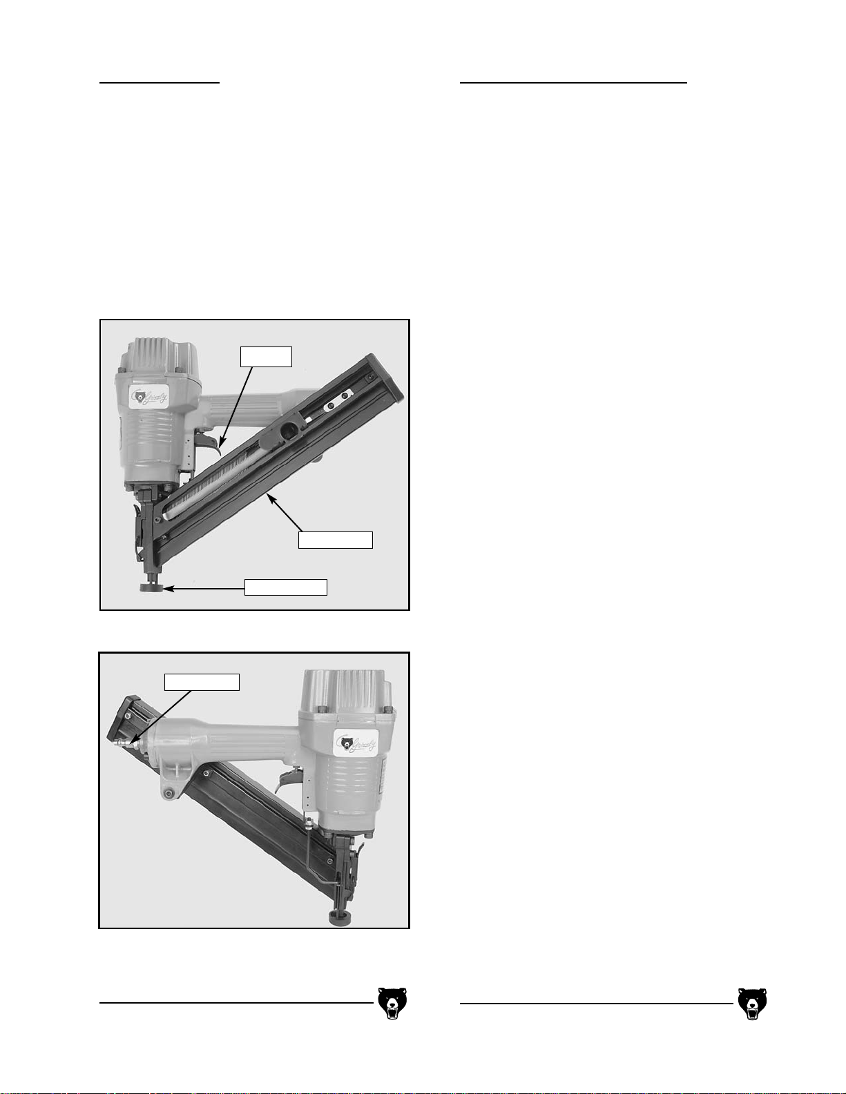
Magazine
Figure 1 shows the front side of the nail gun.
Figure 2 shows the back side of the nail gun.
A. AIR PRESSURE
Air pressure should be set at the minimum
required to set the fastener and must not
exceed 120 p.s.i. Follow all safety items
above and see Section V.B. Consistently
operating at unnecessarily high pressures will
put excessive stress on internal parts which
will lead to premature gun failure.
B. AIR QUALITY
This air gun must be regularly oiled and operated with treated or clean air. It is a precision
tool with close internal tolerances designed for
repetitious use. Wet and dirty air will negatively affect the gun’s performance as well as prematurely destroy internal parts.
To ensure that the best quality air enters
your nail gun:
1. Use an in-line system to automatically oil,
filter, and dry compressed air. Grizzly
offers an in-line regulator / filter / waterseparator / lubricator (G2304). Please
refer to our catalog for price and ordering
information.
2. The intake air filter on your compressor
must be clean and operational.
Periodically clean or replace this filter. It
is your primary line of defense.
3. Drain the compressor air storage tank(s)
often. If conditions are humid, drain up to
several times daily. Water vapor will condense and accumulate in the bottom of
the storage tank(s). The internal metal
parts of the nail gun will be corroded by
the moisture that is passed through the
air supply hose.
4. Keep air hoses as clean as possible inter-
nally. Inspect nipples and couplers for
any dirt and moisture. Blow out prior to
connecting the gun.
V. AIR
Trigger
Air Nozzle
Safety nose
Page 7

- 4 - Grizzly Imports, Inc. G3690
VI. PRE-USE CHECKS VII. OPERATIONS
A. CLEANING
Keep the gun nose as clean as possible. Dirt
and debris have a tendency to work their way
into the gun from the nose. Wipe off any dirt
that collects on the outside of the gun before
connecting it to the air supply.
B. OILING
Keep the gun oiled. Use special pneumatic
tool oil to keep internal parts well lubricated.
This tool oil is available through the Grizzly
Catalog (G2820).
If your air supply is not pre-lubricated, you
must add 2 drops of oil directly into the air
nozzle at the rear of the gun each time the
magazine is loaded. NEVER USE any oil that
will corrode the rubber O-ring seals such as
detergent oils or oils that are used as solvents. Avoid over-oiling.
With these points in mind, you can operate
your nail gun under the best possible conditions for increased dependability and low
overall cost of operation.
IMPORTANT: When you first pick up an air
activated nail gun, ALWAYS ASSUME THAT
IT IS LOADED. Inspect for any nails before
connecting it to the air hose. Do not connect
the air supply until you are in position and
ready to operate the gun.
A. LOADING FASTENERS
To load the gun:
1. Disconnect the air hose if connected.
2. Slide the nails into the magazine through
the rear slot. Figure 3.
3. Pull the spring handle back behind the
last nail and let it go slowly. It will press
against the nails. Figure 4.
Figure 3 shows how to slide the nails in through the
nail slot.
Figure 4 shows pulling back the spring handle to
secure the nails and add pressure.
Page 8

G3690 Grizzly Imports, Inc. - 5 -
VII. OPERATIONS
C. CONNECTING TO AIR
To connect the air hose to the air nozzle at
the rear of the gun:
1. Pull back on the female hose connector
sleeve.
2. Press the fitting onto the nail gun air noz-
zle and release the sleeve. The female
fitting will lock onto the male gun fitting.
3. Listen for any air leaks. If no leaks are
detected, you are ready to test fire the
gun.
Always disconnect the air supply when the
gun is not in use because (1) a pressurized
gun is dangerous and (2) constant pressure will reduce the life of the O-rings
inside the gun.
Prior to operating this nail gun, ensure that all
safety procedures are read and understood.
This tool is very simple to use and effectively
speeds production. However, ease of use and
routine production work may invite accidents.
Please practice safe work habits at all times
and always wear ANSI approved safety equipment.
Figure 5 shows a closeup of the spring handle button.
Press to release pressure.
Figure 6 shows pressing down on the safety stop and
sliding the nails out.
Nail Stop
Spring Handle
Spring Handle Button
Nail Stop
Spring Handle
B. UNLOADING FASTENERS
Fasteners should be removed each time
you finish using the gun.
To unload the gun:
1. Disconnect the air hose if still connect-
ed.
2. Press the button inside the spring handle
finger hole. Figure 5. Guide the spring
handle to the front of the gun. DO NOT
LET THE SPRING HANDLE SNAP
BACK TO ITS RESTING POSITION!
3. Press down on the nail stop and slide the
nails out through the nail slot. Figure 6.
Page 9

- 6 - Grizzly Imports, Inc. G3690
VII. OPERATIONS
D. TEST FIRING
Whenever changing fastener size or composition of material being fastened, the gun should
be tested to ensure that the air pressure is set
correctly and the gun is working properly.
To test fire the gun, wear safety glasses
and follow the steps below:
1. Select a sample workpiece similar in
composition to the type of material you
will be fastening.
2. Firmly press the safety nose down
against the sample piece.
3. Pull trigger.
4. Inspect your results. If the nail is set too
far into the workpiece, reduce the regulated air pressure. If the nail is not set or
protrudes above the work surface,
increase the air pressure. However, do
not exceed the maximum air pressure
recommended for the gun or the hose
(120 p.s.i. for the gun).
5. Disconnect the air hose from the gun
when finished.
6. Unload fasteners. See Section VII.B.
E. ROUTINE USE
To operate the nail gun under routine conditions, always wear safety glasses and:
1. Line up the gun nose with the area on the
workpiece you intend to fasten.
2. Hold the gun straight and perpendicular
to the work surface.
3. Firmly press safety nose against the
workpiece so that the gun nose rests on
the workpiece.
4. Pull trigger.
DO NOT DROP GUN. Repeated dropping will
result in misalignment of the nose and jam-
ming or breakage could occur. This is a preci-
sion tool, not a hammer.
This gun can also be continuously fired by
holding down on the trigger and firmly pressing the safety nose against the workpiece
each time you wish to shoot a fastener.
However, due to the inherent instability
and danger involved with that practice, we
strongly recommend against it.
DO NOT FORGET TO DISCONNECT AIR
SUPPLY AND UNLOAD FASTENERS
WHEN FINISHED USING THE GUN.
Page 10

G3690 Grizzly Imports, Inc. - 7 -
VII. OPERATIONS
Caution: If the gun nose is positioned too
near the edge of the workpiece or is not held
straight, there is a chance that the fastener
will either split the workpiece or be deflected.
Caution: Compressed air is exhausted out of
the top, front of the gun and is directed down
toward the gun nose.
Do not hold the gun so that exhausted air is
blown into your face or someone else’s face.
Exhausted air will cause any dust near the
operating gun to become airborne; use a respirator if using the gun in a dusty environment.
E. ROUTINE USE (CONT’D)
Figure 7 shows using the gun
for a horizontal application.
Figure 8 shows using the gun
for a vertical application.
Page 11

- 8 - Grizzly Imports, Inc. G3690
VIII. INSPECTION
WARNING: All inspections and/or any main-
tenance is to be performed with the air supply
disconnected from the tool.
Inspect and maintain the following items
daily:
1. Check the air gun for any loose bolts or
air leaks. Loose bolts should be retightened. Make sure that all lock washers are
in place. Air leaks are an indication that
internal seals are worn and should be
replaced.
2. Make sure the safety nose and trigger are
functioning properly. Repair as necessary. Do not use the gun with a broken or
modified safety nose.
3. The air gun should be kept clean. Wipe
off with a clean cloth daily.
4. If there is any mechanical problem with
the tool, it must be taken out of service
and repaired. If waiting for parts or repair,
the tool must be tagged “do not use” and
removed from the work area.
5. Inspect air hoses and fittings for wear and
tear and replace if necessary.
6. Inspect the air compressor to ensure that
it is operating properly. Follow the manufacturer’s recommended maintenance
schedule.
7. Inspect the automatic lubricating system
if applicable and fill as required. Inspect
the in-line air and water filters if applicable and change or clean as necessary.
8. Inspect the compressor regulator and/or
in-line regulator to ensure that they are
set correctly. Adjust accordingly.
9. Oil regularly. See Section VI.B.
Page 12

G3690 Grizzly Imports, Inc. - 9 -
IX. MAINTENANCE
A. JAMMING
To repair a jam:
1. Disconnect gun from the air supply.
2. Remove any fasteners remaining in the
gun.
3. Open the nose by unlocking the safety
clip.
4. Using needle nose pliers, remove any
bent fasteners lodged in the gun nose.
5. Close the nose and re-lock the safety
clip.
6. Re-load fasteners and connect nail gun
to the air supply.
7. Make sure the safety nose is functioning
correctly and that it slides freely in its
guide. Test fire into a sample piece after
following all operational and safety procedures discussed earlier.
If jamming persists, make sure you are using
fasteners within the size range of this gun. If
jamming is due to worn or broken parts, repair
or replace them before placing the gun back
into service. For example, a worn or damaged
driver may cause jamming. If the driver tip is
worn, you may be able to recondition the tip
by filing it square again. In any event, you
must remove the damaged driver from the
gun. See Section IX.B.
Maintenance requirements are minimal for
this nail gun. The two most common problems
with any nail gun are jamming and damaged
drivers. In both cases, the gun will need to be
partially diassembled to make the repairs.
The third most common problem is replacing
worn out O-rings. This is quite easily done, but
extensive disassembly will be required. We
suggest consulting with the Grizzly service
staff for special instructions if needed. Grizzly
has replacement parts and a special O-ring
rebuilding kit available for this tool. Please call
or write the appropriate service location listed
on page one of this manual for prices and
ordering information.
Again, if repairs become necessary that are
beyond the scope of this manual, do not hesitate to call or write the appropriate service
location.
Figure 9 shows the safety clip that keeps the nose of
the gun closed.
Figure 10 shows the nose open and the jammed nail
exposed. Remove with needle nose pliers.
Page 13

- 10 - Grizzly Imports, Inc. G3690
IX. MAINTENANCE
B. DAMAGED DRIVER
To remove the driver:
1. Disconnect gun from the air supply and
remove any fasteners from the magazine.
2. Loosen the 4 cap screws securing the
gun cap to the gun body sequentially.
3. Remove the four cap screws and the gun
cap and place them to one side.
4. With your fingers, reach into the air cylin-
der, grasp the main piston, and pull out
the driver.
5. Inspect driver condition and repair or
replace as necessary. Replacement drivers are sold pre-attached to the main
piston and are referred to as the “complete driver unit”.
C. O-RINGS AND RE-ASSEMBLY
Since the gun is disassembled, inspect the
condition of the visible O-rings. If the O-rings
show signs of wear and tear, they should be
replaced. Inspect the surfaces where the Orings seal for any possible rough spots which
will erode the new O-rings. When replacing
the O-rings, make sure that there is no dirt or
grit in the groove where the O-rings seat. Do
not stretch the O-rings or nick them on any
sharp edges or burrs. If cleaning parts with a
solvent, do not use a solvent that may deteriorate the O-rings.
To re-assemble the gun:
1. Before replacing O-rings, lubricate them
with a light grease that is non corrosive to
rubber.
2. IMPORTANT: Carefully position the dri-
ver tip into the plastic driver insert from
the top of the nail gun. You may have to
wiggle the driver so the main piston seats
into the cylinder. The driver has a Tshaped cross section and will only fit one
way. If the driver is not seating, do not
force it. Remove the driver unit, rotate
180°, and try to reinstall it.
3. Replace the cap on top of the gun.
Tighten the cap screws sequentially. If
the cap screws are not tightened evenly, the cap will not seat correctly, air
will leak, and the gun will not function.
Ensure that the washers are installed
under the cap screw heads.
4. Re-check all bolts to make sure they are
tight and test the gun to ensure that it
works properly. See the following paragraph.
NOTE: Before putting the gun back together,
read through Section IX.C.
Gun Cap
Cap Screws
Driver
Main Piston
Air Cylinder
Figure 11 shows the gun partially disassembled to
repair or replace the driver.
Page 14

G3690 Grizzly Imports, Inc. - 11 -
IX. MAINTENANCE X. TROUBLESHOOTING
D. TESTING AFTER ASSEMBLY
To initially test the gun after a repair procedure:
1. Put on your safety glasses, reduce the
regulated air pressure to 30 PSI. Do not
put any fasteners into the magazine.
Connect the air hose.
NOTE: It is important to reduce the initial test pressure so that damage to
the gun does not occur when firing
without any fasteners in the magazine.
2. Check for any leaking air. You will hear it
hissing or feel it rushing through the
spaces.
3. If everything sounds normal, press the
safety nose down on a piece of wood and
pull the trigger a couple of times. Air
should be exhausted normally each time.
4. Disconnect the air hose. Adjust the regu-
lated air pressure back up to the minimum required to set your fasteners. Load
the magazine with recommended fasteners.
5. Re-connect the nail gun to the air supply.
6. Press the safety nose on a suitable test
material and pull the trigger. If the gun is
still not working properly, re-check your
repair procedure or call the appropriate
service location for advice.
See Section VII.D and VII.E. for more infor-
mation about testing and routine use.
This section covers some other potential problems and possible causes. If you have taken
the gun apart before, as in the above section,
you will realize that most problems can be
repaired on the job site with a few basic parts.
If you are heavily dependent upon this tool for
production work, it makes good sense to have
an O-ring repair kit and a complete driver unit
on hand just in case a problem does develop.
The following list describes some potential
problems and solutions.
1. LEAKS: A leak can usually be fixed by
simply loosening and retightening the
cap screws on the gun cap symmetrically or providing more lubricant to
the O-rings.
2. If the driver does not return to its starting
position, then the main piston O-ring may
be worn or broken.
3. If air constantly leaks at the exhaust port,
then the head valve piston O-ring may be
worn or broken.
4. If air constantly leaks at the trigger, then
the trigger system O-rings may be worn
or broken.
5. If the gun misfires or over-drives the fas-
tener into the workpiece without manually changing the air pressure, then the
bumper may be worn or broken.
6. If the wrong type of oil has been used for
lubrication, O-rings may swell and dislodge from their grooves. This could
cause leaks anywhere in the gun.
Again, if you have a problem and would like
assistance, please call the appropriate service
department. They will be glad to assist you.
Page 15

- 12 - Grizzly Imports, Inc. G3690
LIMITED WARRANTY
Grizzly Imports, Inc. warrants every product it
sells for a period of 1 year to the original pur-
chaser from the date of purchase. This warranty does not apply to defects due directly or
indirectly to misuse, abuse, negligence, accidents, repairs or alterations or lack of maintenance. This is Grizzly’s sole written warranty
and any and all warranties that may be
implied by law, including any merchantability
or fitness, for any particular purpose, are hereby limited to the duration of this written warranty. We do not warrant or represent that the
merchandise complies with the provisions of
any law or acts unless the manufacturer so
warrants. In no event shall Grizzly’s liability
under this warranty exceed the purchase price
paid for the product and any legal actions
brought against Grizzly shall be tried in the
State of Washington, County of Whatcom.
We shall in no event be liable for death,
injuries to persons or property or for incidental, contingent, special, or consequential damages arising from the use of our products.
To take advantage of this warranty, contact us
by mail or phone and give us all the details.
We will then issue you a “Return Number”
which must be clearly posted on the outside
as well as the inside of the carton. We will not
accept any item back without this number.
Proof of purchase must accompany the merchandise.
The manufacturers reserve the right to
change specifications at any time because
they constantly strive to achieve better quality
equipment. We make every effort to ensure
that our products meet high quality and durability standards and we hope you never need
to use this warranty.
The following pages contain general machine
specifications, a parts diagram and list, and
index for your Model G3690 Nail Gun.
If you need parts or help in assembling your
machine, or if you need operational information, we encourage you to call the appropriate
Regional Service Department. Our highly
trained service technicians will be glad to help
you.
If you have any comments or concerns dealing specifically with this manual, please write
to our Bellingham, Washington location using
the address listed in the Introduction.
XI. WARRANTY AND
RETURNS
XII. CLOSURE
Page 16

G3690 Grizzly Imports, Inc. - 13 -
GRIZZLY MODEL G3690 ANGLE FINISH NAILER
Operating Air Pressure:
Softwood:..........................................................................................................80 to 100 PSI
Maximum Air Pressure ................................................................................................120 PSI
Hardwood: ........................................................................................................90 to 120 PSI
Maximum Air Pressure ................................................................................................120 PSI
Nail Length: ........................................................................1-
1
/2" to 2-1/2" Clipped Head Finish Nails
Nail Gauge:............................................................................................................................14 or 15
Magazine Capacity:............................................................................100 @15 Ga. or 90 @ 14 Ga.
Construction:............................................................................Cast Aluminum and Hardened Steel
Coupling System: ..................................................................................................................
1
/4" NPT
Recommended Lubricating Oil: ........................................................................Pneumatic Tool Oil
Gun Weight:..........................................................................................................................5.95 lbs.
Parts and Accessories:
A rebuilding kit is available from Grizzly and includes all O-rings. The rebuilding kit and other
parts can be individually ordered through the appropriate service department.
Grizzly also carries an air hose, an in-line regulator/filter/water-separator/lubricator, quick connect couplers, and a complete line of fasteners for this gun. Please refer to a current Grizzly catalog for price and ordering information.
Specifications, while deemed accurate, are not guaranteed.
XIII. TOOL DATA
Page 17

- 14 - Grizzly Imports, Inc. G3690
XIV. PARTS DIAGRAM
101
112
6
303
415
305
302
304
434
433
42
428
436
424
438
429
427
414
430
431
433
215
425
437
213
214
A
422
436
422
423
216
406
416
201
407
439
202
421
442
432
203
405
417
204
408
418
205
409
401
420
206
207
410
208
210
411
209
445
212
446
211
440
412
301
113
104
102
114A
103
114
105
115
106
121
122
107
123
116
124
109
125
110
117
402
403
120
108
404
441
119
111
413
444
443
118
A
126
B
Page 18

G3690 Grizzly Imports, Inc. - 15 -
305 PSB15M CAP SCREW M5 - 0.8 x 20
306 G2308 QUICK CONNECT
1
/4" NPT
401 P3690401 DRIVER GUIDE
402 P3690402 DRIVER GUIDE COVER B
403 PLW03M LOCK WASHER 6mm
404 PSB06M CAP SCREW M6 - 1.0 x 25
405 PLN01M LOCK NUT M4 - 0.7
406 P3690406 SAFETY GUIDE
407 PRP16M ROLL PIN 3 x 25
408 P3690408 SAFETY DRIVER
409 PN04M HEX NUT M4 - 0.7
410 P3690410 SAFETY
411 P3690411 SPRING
412 P3690412 DRIVER GUIDE COVER A
413 PSB33M CAP SCREW M5 - 0.8 x 12
414 P3690414 MAGAZINE
415 P3690415 STEEL CHANNEL
416 P3690416 PUSHER
417 P3690417 NYLON ROLLER
418 P3690418 SPRING
420 PSB03M CAP SCREW M5 - 0.8 x 8
421 P3690421 PIN EJECT EXTERNAL HANDLE
422 P3690422 STEEL PIN
423 PLN02M LOCK NUT M5 - 0.8
424 P3690424 STOP PLATE
425 P3690425 MOUNTING BRACKET
426 P3690426 BUTTON HD SCRW M4 - 0.7 x 10
427 PLN01M LOCK NUT M4 - 0.7
428 P3690428 PROTECTING COVER
429 PLN01M LOCK NUT M4 - 0.7
430 PLW02M LOCK WASHER 4mm
431 PSB18M CAP SCREW M4 - 0.7 x 8
432 PSB23M CAP SCREW M4 - 0.7 x 12
433 PW02M FLAT WASHER 5mm
434 PSB53M CAP SCREW M5 - 0.8 x 18
435 PLN01M LOCK NUT M5 - 0.8
436 P3690436 BUTTON HD SCRW M4 - 0.7 x 8
437 PLN02M LOCK NUT M4 - 0.7
438 PRP42M ROLL PIN 3 x 34
439 PLW02M LOCK WASHER 4mm
440 P3690440 RUBBER FOOT
441 PLW01M LOCK WASHER 5mm
442 P3690442 SPRING
443 P3690443 LOCK HANDLE UNIT
444 PRP43M ROLL PIN 3 x 22
445 PRP44M ROLL PIN 3 x 10
446 PRP02M ROLL PIN 3 x 16
REF# PART# DESCRIPTION REF# PART# DESCRIPTION
XV. PARTS LIST
101 PSB06M CAP SCREW M6 - 1.0 x 25
102 PLW03M LOCK WASHER 6mm
103 P3690101 CAP
104 PSS07M SETSCREW M5 - 0.8 x 5
105 P3690105 GASKET
106 P3690106 SEAL
107 P3690107 SPRING
108 P3690108 O-RING
109 P3690109 O-RING
110 P3690110 VALVE PISTON
111 P3690111 COLLAR
112 P3690112 O-RING
113 P3690113 MAIN PISTON
114 P3690114 DRIVER
114A P3690114A COMPLETE DRIVER UNIT
115 P3690115 O-RING
116 P3690116 CYLINDER
117 P3690117 CYLINDER RING
118 P3690118 BUMPER
119 P3690119 CYLINDER SPACER
120 P3690120 O-RING
121 P3690121 GASKET
122 P3690122 DRIVER GUIDE
123 P3690123 BASE
124 PLW03M LOCK WASHER 6mm
125 PSB02M CAP SCREW M6 - 1.0 x 20
126 P3690126 CYLINDER PRESS RING
201 P3690201 O-RING
202 P3690202 VALVE
203 P3690203 O-RING
204 P3690204 O-RING
205 P3690205 O-RING
206 P3690206 VALVE PLUNGER
207 P3690207 O-RING
208 P3690208 SPRING
209 P3690209 PLUNGER
210 P3690210 O-RING
211 P3690211 PLUNGER CAP
212 P3690212 O-RING
213 P3690213 SECONDARY TRIGGER
214 P3690214 TRIGGER
215 PRP02M ROLL PIN 3 x 16
216 PRP16M ROLL PIN 3 x 25
301 P3690301 GUN BODY
302 P3690302 GASKET
303 P3690303 END CAP
304 PLW01M LOCK WASHER 5mm
Page 19

- 16 - Grizzly Imports, Inc. G3690
A
Addresses....................................................1
Air Pressure ................................................3
Air Quality ....................................................3
C
Clean Air Hoses ..........................................3
Cleaning ......................................................4
Closure ......................................................12
Commentary ................................................1
Connecting to Air ........................................5
D
Damaged Driver ........................................10
F
Fax Numbers ..............................................1
H
Horizontal Nailing ........................................7
Humid Air ....................................................3
I
Inspection ....................................................8
Introduction ..................................................1
Items List ....................................................3
J
Jamming ......................................................9
L
Loading Fasteners ......................................4
M
Maintenance ..........................................9-11
O
Oiling............................................................4
Operations ................................................4-7
O-rings ........................................................4
O-rings and Re-assembly..........................10
P
Parts Diagram............................................14
Parts List....................................................14
Phone Numbers ..........................................1
Pneumatic Tool Oil ......................................4
Pre-Use Checks ..........................................4
R
Removing the Driver..................................10
Routine Use..............................................6-7
S
Safety Rules for Nail Guns ..........................2
Spring Handle ..............................................5
T
Test Firing....................................................6
Testing after Assembly ..............................11
Tool Data ..................................................13
Troubleshooting ........................................11
U
Unloading Fasteners....................................5
Unpacking....................................................3
V
Vertical Nailing ............................................7
W
Warranty and Returns ..............................12
FIGURES
Figure 1 shows the front side of the nail gun.
....................................................................3
Figure 2 shows the back side of the nail gun.
....................................................................3
Figure 3 shows how to slide the nails in
through the nail slot. ....................................4
Figure 4 shows pulling back the spring han-
dle to secure the nails and add pressure. ..4
Figure 5 shows a closeup of the spring han-
dle button. Press to release pressure. ........5
Figure 6 shows pressing down on the safety
stop and sliding the nails out. ......................5
Figure 7 shows using the gun for a horizon-
tal application...............................................6
Figure 8 shows using the gun for a vertical
application. ..................................................7
Figure 9 shows the safety clip that keeps the
nose of the gun closed. ..............................9
Figure 10 shows the nose open and the
jammed nail exposed...................................9
Figure 11 shows the gun partially disassem-
bled to repair or replace the driver. ..........10
XVI. INDEX
 Loading...