

Page 1

BELT/DISC SANDER
MODEL G3105
INSTRUCTION MANUAL
COPYRIGHT © 1991 BY GRIZZLY INDUSTRIAL, INC.
WARNING: NO PORTION OF THIS MANUAL MAY BE REPRODUCED IN ANY SHAPE
OR FORM WITHOUT THE WRITTEN APPROVAL OF GRIZZLY INDUSTRIAL, INC.
REVISED APRIL, 1999. PRINTED IN U.S.A.
Page 2

Page 3

G3105 Combination Sander -1-
Table Of Contents
PAGE
1. SAFETY
SAFETY RULES FOR ALL TOOLS ......................................................................2-3
ADDITIONAL SAFETY INSTRUCTIONS FOR SANDERS ......................................4
2. CIRCUIT REQUIREMENTS
110V OPERATION ....................................................................................................5
FUSING ....................................................................................................................5
EXTENSION CORDS ................................................................................................5
GROUNDING ............................................................................................................5
3. INTRODUCTION
COMMENTARY ........................................................................................................6
UNPACKING..............................................................................................................7
PARTS INVENTORY ................................................................................................7
CLEAN UP ................................................................................................................8
SITE CONSIDERATIONS ........................................................................................8
4. ASSEMBLY
OVERVIEW................................................................................................................9
OUTSIDE BELT GUARD ........................................................................................10
BELT TABLE ..........................................................................................................10
LOWER BELT GUARD............................................................................................10
DISC TABLE BRACKET..........................................................................................11
DISC TABLE............................................................................................................11
HORIZONTAL STOP ..............................................................................................11
5. ADJUSTMENTS
BELT TENSION ......................................................................................................12
BELT TRACKING ....................................................................................................12
BELT PLATEN ........................................................................................................12
6. OPERATIONS
TEST RUN ..............................................................................................................13
GENERAL SANDING ..............................................................................................13
BELT SANDING ......................................................................................................13
INSIDE SANDING ..................................................................................................14
CONTOUR SANDING ............................................................................................14
SHARPENING ........................................................................................................14
7. MAINTENANCE
GENERAL................................................................................................................15
SANDER TABLES ..................................................................................................15
LUBRICATION ........................................................................................................15
DISC & BELT REPLACEMENT ..............................................................................15
8. CLOSURE ....................................................................................................................16
MACHINE DATA......................................................................................................................17
PARTS DIAGRAMS & LISTS ............................................................................................18-19
TROUBLESHOOTING ............................................................................................................20
WARRANTY AND RETURNS..................................................................................................22
Page 4
-2- G3105 Combination Sander
Safety Instructions For Power Tools
SECTION 1: SAFETY
5. KEEP CHILDREN AND VISITORS
AWAY. All children and visitors should be
kept a safe distance from work area.
6. MAKE WORK SHOP CHILD PROOF with
padlocks, master switches, or by removing
starter keys.
7. DON’T FORCE TOOL. It will do the job
better and safer at the rate for which it was
designed.
8. USE RIGHT TOOL. Don’t force tool or
attachment to do a job for which it was not
designed.
1. KEEP GUARDS IN PLACE and in working
order.
2. REMOVE ADJUSTING KEYS AND
WRENCHES. Form habit of checking to
see that keys and adjusting wrenches are
removed from tool before turning on.
3. KEEP WORK AREA CLEAN. Cluttered
areas and benches invite accidents.
4. DON’T USE IN DANGEROUS ENVIRONMENT. Don’t use power tools in damp or
wet locations, or where any flammable or
noxious fumes may exist. Keep work area
well lighted.
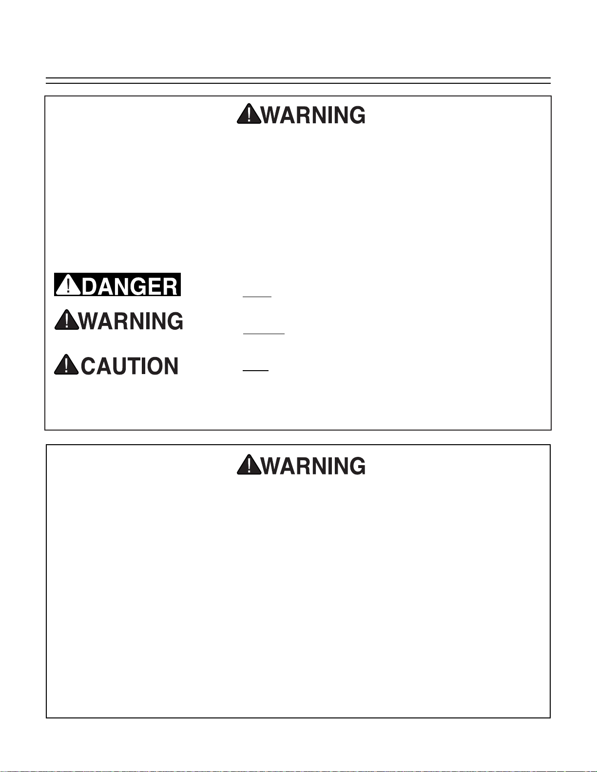
For Your Own Safety Read Instruction
Manual Before Operating This Equipment
Indicates an imminently hazardous situation which, if not
avoided, WILL
result in death or serious injury.
Indicates a potentially hazardous situation which, if not
avoided, COULD result in death or serious injury.
Indicates a potentially hazardous situation which, if not
avoided, MAY
result in minor or moderate injury. It may also
be used to alert against unsafe practices.
This symbol is used to alert the user to useful information
about proper operation of the equipment.
The purpose of safety symbols is to attract your attention to possible hazardous conditions.
This manual uses a series of symbols and signal words which are intended to convey the level
of importance of the safety messages. The progression of symbols is described below.
Remember that safety messages by themselves do not eliminate danger and are not a substitute for proper accident prevention measures.
NOTICE
Page 5
G3105 Combination Sander -3-
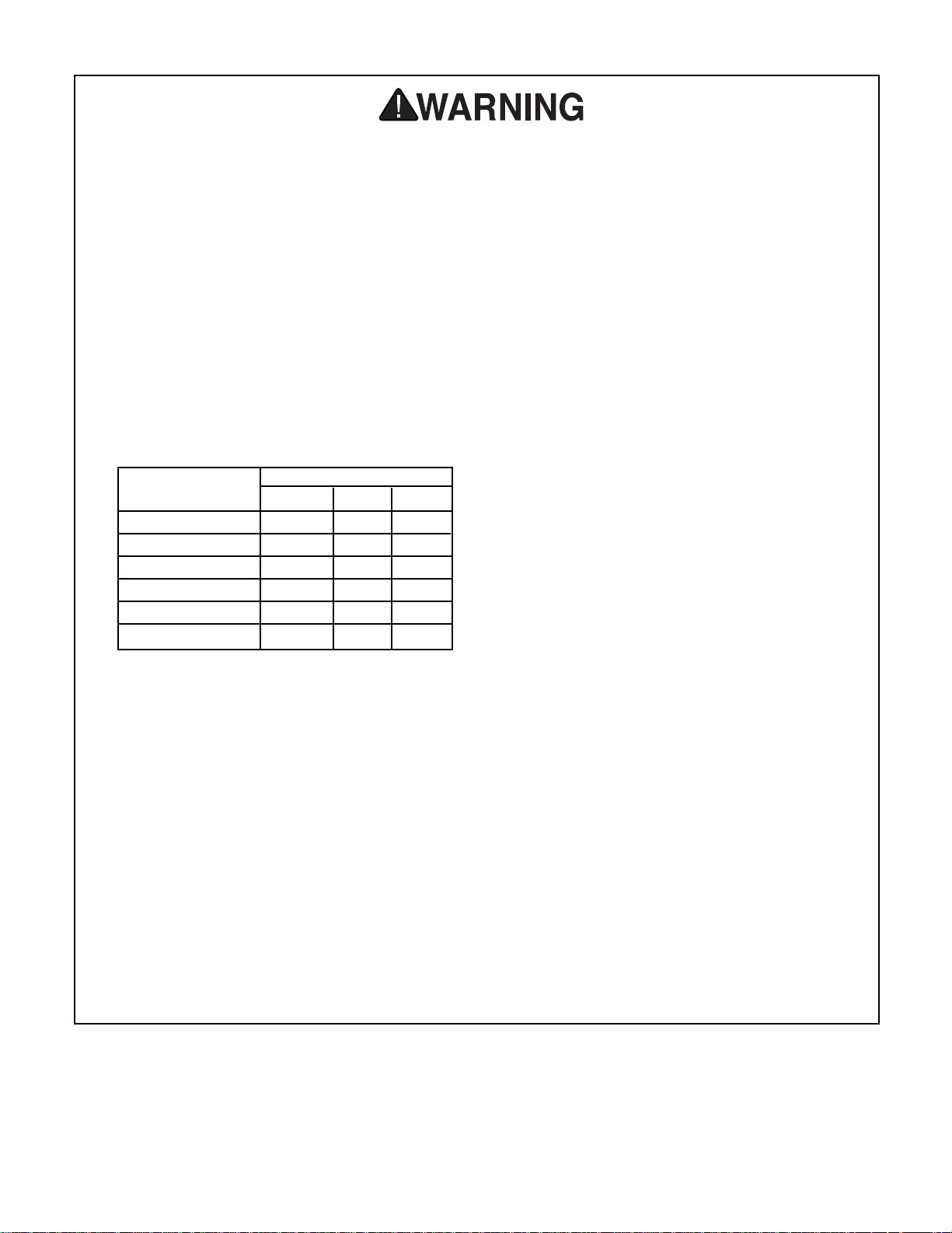
9. USE PROPER EXTENSION CORD. Make
sure your extension cord is in good condition. Conductor size should be in accordance with the chart below. The amperage
rating should be listed on the motor or tool
nameplate. An undersized cord will cause a
drop in line voltage resulting in loss of
power and overheating. Your extension
cord must also contain a ground wire and
plug pin. Always repair or replace extension cords if they become damaged.
Minimum Gauge for Extension Cords
10. WEAR PROPER APPAREL. Do not wear
loose clothing, gloves, neckties, rings,
bracelets, or other jewelry which may get
caught in moving parts. Non-slip footwear
is recommended. Wear protective hair covering to contain long hair.
11. ALWAYS USE SAFETY GLASSES. Also
use face or dust mask if cutting operation is
dusty. Everyday eyeglasses only have
impact resistant lenses, they are NOT safety glasses.
12. SECURE WORK. Use clamps or a vise to
hold work when practical. It’s safer than
using your hand and frees both hands to
operate tool.
LENGTH
AMP RATING 25ft 50ft 100ft
0-6 18 16 16
7-10 18 16 14
11-12 16 16 14
13-16 14 12 12
17-20 12 12 10
21-30 10 10 No
Safety Instructions For Power Tools
13. DON’T OVERREACH. Keep proper foot-
ing and balance at all times.
14. MAINTAIN TOOLS WITH CARE. Keep
tools sharp and clean for best and safest
performance. Follow instructions for lubricating and changing accessories.
15. DISCONNECT TOOLS before servicing
and changing accessories, such as blades,
bits, cutters, and the like.
16. REDUCE THE RISK OF UNINTENTIONAL STARTING. Make sure switch is in off
position before plugging in.
17. USE RECOMMENDED ACCESSORIES.
Consult the owner’s manual for recommended accessories. The use of improper
accessories may cause risk of injury.
18. CHECK DAMAGED PARTS. Before fur-
ther use of the tool, a guard or other part
that is damaged should be carefully
checked to determine that it will operate
properly and perform its intended function.
Check for alignment of moving parts, binding of moving parts, breakage of parts,
mounting, and any other conditions that
may affect its operation. A guard or other
part that is damaged should be properly
repaired or replaced.
19. NEVER LEAVE TOOL RUNNING UNATTENDED. TURN POWER OFF. Don’t
leave tool until it comes to a complete stop.
Page 6
-4- G3105 Combination Sander
Additional Safety Instructions For Sanders
No list of safety guidelines can be complete. Every shop environment is different.
Always consider safety first, as it applies to
your individual working conditions. Use
this and other machinery with caution and
respect. Failure to follow guidelines could
result in serious personal injury, damage to
equipment or poor work results.
1. BE AWARE OF BELT or disc rotation when
sanding.
2. KEEP FINGERTIPS AWAY from the mov-
ing belt or disc. Serious injury could result if
skin contacts abrasives or moving parts.
3. NEVER USE EXCESSIVE FORCE when
sanding. Doing this greatly increases the
chances of personal injury and motor overload.
4. ALWAYS FEED THE WORK against the
direction of rotation.
5. EVEN IF YOU HAVE A reliable method of
dust collection, use a dust mask or respirator when sanding, as well as eye and ear
protection.
6. IF THERE IS ANY doubt as to the stability
or integrity of the material to be sanded,
don’t sand it.
7. DO NOT OPERATE SANDER with a dam-
aged or badly worn disc or belt.
8. WHEN DISC SANDING, feed material into
the portion of the disc spinning down toward
the table.
9. TIE BACK LONG HAIR and remove any
loose-fitting clothing or jewelry that could be
caught up in the sander’s disc, belt, or other
moving machine parts.
10. HABITS — GOOD OR BAD — are hard to
break. Develop good habits and safety will
become second nature to you.
Like all power tools, there is danger associated with the Model G3105 Belt/Disc
Sander. Accidents are frequently caused by
lack of familiarity or failure to pay attention.
Use this tool with respect and caution to
lessen the possibility of operator injury. If
normal safety precautions are overlooked
or ignored, serious personal injury may
occur.
Operation of this equipment has the potential to propel debris into the air which can
cause eye injury. Always wear safety glasses or goggles when operating equipment.
Everyday glasses or reading glasses only
have impact resistant lenses, they are not
safety glasses. Be certain the safety glasses you wear meet the appropriate standards of the American National Standards
Institute (ANSI).
Page 7

G3105 Combination Sander -5-
110V Operation
SECTION 2: CIRCUIT REQUIREMENTS
A 15-amp fuse or circuit breaker should be used
when fusing this combination sander. Circuits
rated any higher are not adequate to protect the
motor from power surges.
Equipment returned to us for service that shows
evidence of being over-fused will be repaired or
replaced totally at the customer’s expense,
regardless of the present warranty status.
Fusing
If you find it necessary to use an extension cord
with the Model G3105, make sure the cord is
rated Hard Service (grade S) or better. Refer to
the chart in the standard safety instructions to
determine the minimum gauge for the extension
cord. The extension cord must also contain a
ground wire and plug pin. Always repair or
replace extension cords when they become worn
or damaged.
Extension Cords
Grounding
This equipment must be grounded. Verify
that any existing electrical outlet and circuit
you intend to plug into is actually grounded. If it is not, it will be necessary to run a
separate 12 A.W.G. copper grounding wire
from the outlet to a known ground. Under
no circumstances should the grounding pin
from any three-pronged plug be removed.
Serious injury may occur.
In the event of an electrical short, grounding
reduces the risk of electric shock by providing a
path of least resistance to disperse electric current. This tool is equipped with a power cord hav-
ing an equipment-grounding conductor. See
Figure 1. The outlet must be properly installed
and grounded in accordance with all local codes
and ordinances.
The Model G3105 is wired for 110/120V, single
phase operation only. The
1
⁄2 HP motor will safely
draw 3 amps at 110V. If you operate this sander
on any circuit that is already close to its capacity,
it might blow a fuse or trip a circuit breaker.
However, if an unusual load does not exist and a
power failure still occurs, contact a qualified electrician or our service department.
Figure 1. Grounded plug configuration.
Page 8

-6- G3105 Combination Sander
SECTION 3: INTRODUCTION
We are proud to offer the Grizzly Model G3105
Combination Belt and Disc Sander. The Model
G3105 is part of a growing Grizzly family of fine
woodworking machinery. When used according
to the guidelines set forth in this manual, you can
expect years of trouble-free, enjoyable operation
and proof of Grizzly’s commitment to customer
satisfaction.
The Model G3105 is a combination 1" x 42" belt
and 6" disc sander that is capable of a wide variety of operations. The 1" wide belt enables you to
sand small or finely-detailed pieces, or sharpen
knives and tool blades as described later in this
manual. With the 6" disc and table, larger surfaces can be sanded at many different angles.
The G3105 comes complete with motor and electrical package.
A number of sanding discs and belts for the
Model G3105 are available through the Grizzly
catalog.
We are also pleased to provide this manual with
the Model G3105. It was written to guide you
through assembly, review safety considerations,
and cover general operating procedures. It represents our effort to produce the best documentation possible. If you have any comments regarding this manual, please write to us at the address
below:
Grizzly Industrial, Inc.
C
/
O Technical Documentation
P.O. Box 2069
Bellingham, WA 98227-2069
Most importantly, we stand behind our machines.
If you have any service questions or parts
requests, please call or write us at the location
listed below.
Grizzly Industrial, Inc.
1203 Lycoming Mall Circle
Muncy, PA 17756
Phone: (570) 546-9663
Fax: (800) 438-5901
E-Mail: techsupport@grizzly.com
Web Site: http://www.grizzly.com
The specifications, drawings, and photographs
illustrated in this manual represent the Model
G3105 as supplied when the manual was prepared. However, owing to Grizzly’s policy of continuous improvement, changes may be made at
any time with no obligation on the part of Grizzly.
Whenever possible, though, we send manual
updates to all owners of a particular tool or
machine. Should you receive one, we urge you to
insert the new information with the old and keep
it for reference.
To operate this, or any power tool, safely
and efficiently, it is essential to become as
familiar with its characteristics as possible.
The time you invest before you begin to use
your Model G3105 will be time well spent.
DO NOT operate this machine until you are
completely familiar with the contents of this
manual. Make sure you read and understand all of the safety procedures. If you do
not understand something, DO NOT operate
the machine.
Commentary
Page 9

G3105 Combination Sander -7-
Unpacking
This Combination Sander is shipped from the
manufacturer in a carefully packed carton. If you
discover the machine is damaged after you’ve
signed for delivery, and the truck and driver are
gone, you will need to file a freight claim with the
carrier. Save the containers and all packing
materials for possible inspection by the carrier or
its agent. Without the packing materials, filing a
freight claim can be difficult. If you need assis-
tance determining whether you need to file a
freight claim, or with the procedure to file one,
please contact our Customer Service.
Parts Inventory
After all the parts have been removed from the
carton, you should have:
• Sanding Unit
• Belt Guard
• Disc Table Bracket
• Disc Table
• Belt Table
• Miter Gauge
• 4 Knobs
• Fasteners
• Sanding Belt
• 4mm Allen
®
Wrench
• 8mm Allen
®
Wrench
When you are completely satisfied with the condition of your shipment, you should inventory its
parts.
NOTICE
A full parts list and breakdown can be found
toward the end of this manual. For easier
assembly, or to identify missing parts,
please refer to the detailed illustrations at
the end of the manual.
Hardware Location Qty
Hex Bolts
5
/16" - 18 x 1/2" Disc Table Bracket 2
Flat Washers
5
/16" Disc Table Bracket 4
Knobs Disc Table Bracket 2
Knobs Belt Guard 2
Flat Washer
3
/8" Belt Table Bracket 1
Cap Screw
3
/8" - 16 x 3/4" Belt Table Bracket 1
Screw Lower Belt Guard 1
Page 10

-8- G3105 Combination Sander
Clean Up
BENCH LOAD
Your G3105 Combination Sander represents a
relatively large weight load in a small footprint. Be
sure that your workbench is adequately reinforced to support the weight of the sander.
WORKING CLEARANCES
Working clearances can be thought of as the distances between machines and obstacles that
allow safe operation of every machine without
limitation. Ensure that your working area offers
plenty of room for free movement and a substantial amount of distance between you and others
that may be working in your shop area.
LIGHTING AND OUTLETS
Lighting should be bright enough to eliminate
shadow and prevent eye strain. Electrical circuits
should be dedicated or large enough to handle
combined motor amp loads. Outlets should be
located near each machine so power or extension cords are not obstructing high-traffic areas.
Be sure to observe local electrical codes for proper installation of new lighting, outlets, or circuits.
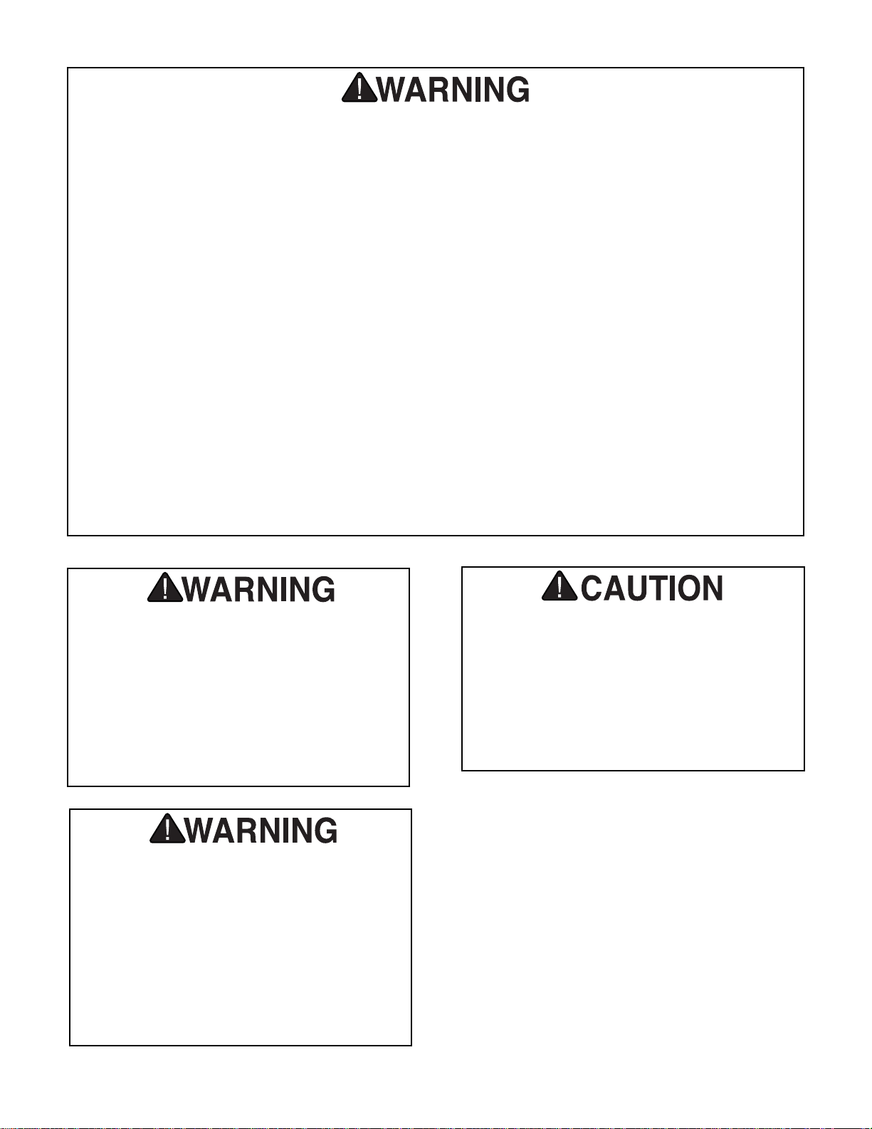
Make your shop “child safe”. Ensure that
your workplace is inaccessible to youngsters by closing and locking all entrances
when you are away. Never allow visitors in
your shop when assembling, adjusting or
operating equipment.
Site Consideration
Unpainted machine surfaces may be coated with
a waxy oil to protect it from corrosion during shipment. Remove this protective coating with a solvent cleaner or citrus-based degreaser. Avoid
chlorine-based solvents as they may damage
painted surfaces should they come in contact.
Always follow the usage instructions on the product you choose for clean up.
Many of the solvents commonly used to
clean machinery can be highly flammable,
and toxic when inhaled or ingested. Always
work in well-ventilated areas far from
potential ignition sources when dealing
with solvents. Use care when disposing of
waste rags and towels to be sure they do
not create fire or environmental hazards.
Keep children and animals safely away
when cleaning and assembling this
machine.
Do not use gasoline or other petroleumbased solvents to remove this protective
coating. These products generally have low
flash points which makes them extremely
flammable. A risk of explosion and burning
exists if these products are used. Serious
personal injury may occur.
Page 11

G3105 Combination Sander -9-
SECTION 4: ASSEMBLY
Overview
All die-cut metal parts have a sharp edge
(called “flashing”) on them after they are
formed. This is generally removed at the
factory. Sometimes a bit of flashing might
escape inspection, and the sharp edge may
cause cuts or lacerations when handled.
Please examine the edges of all die-cut
metal parts and file or sand the edge to
remove the flashing before handling.
Most of your G3105 Belt and Disc Sander has
been assembled at the factory. The few pieces
that remain should go together quickly and easily. Only a few common tools are required to
assemble your Combination Sander. Specifically,
these are: 12mm open end wrench, Phillips
®
head screwdriver, 8mm Allen®wrench (provided
with machine). The following list provides the recommended order in which the sander should be
assembled:
• Outside Belt Guard
• Belt Table
• Disc Table Bracket
• Disc Table
Before beginning the assembly process, we recommend you become familiar with the Model
G3105 Combination Sander’s parts and controls.
See Figure 2below, as well as the Parts Diagram
at the end of the manual for details.
Figure 2. Major components of the G3105.
TENSION KNOB
MITER GAUGE
BELT TABLE
GUARD MOUNTING KNOB
TRACKING SCREW
SWITCH
TABLE TRUNNION
ANGLE GUIDE SCREW
SANDING DISC
DISC TABLE
HORIZONTAL ADJUSTMENT SCREW
BELT TABLE ADJUSTMENT SCREW
MOTOR BODY
Page 12

-10- G3105 Combination Sander
Outside Belt Guard
Using two of the knobs provided, mount the outside belt guard to the cast-iron, inner belt guard.
See Figure 3.
Figure 3. Outside belt guard attachment points.
Guard
Mounting
Holes
Belt Table
Use the 3/
8" - 16 x
3
/
4" cap screw and
3
/
8" washer
to secure the table to the inner belt guard. The
slotted bracket is provided to enable maximum
adjustment. See Figure 4. Use a machinist’s
square to set the table to 90˚ to the face of the
sanding belt. The table can also be tilted down an
additional 45˚. Simply loosen the cap screw and
adjust to the desired angle.
Figure 4. Belt table properly mounted.
Belt Table
Adj Cap Screw
DO NOT attempt to turn on the machine
during any step of the assembly process,
unless instructed otherwise. Make sure the
power switch is in the OFF position and the
plug is disconnected from its power source
during assembly. Failure to do so could
result in injury or electrical shock.
Page 13

G3105 Combination Sander
-11-
Disc Table Bracket
The disc table bracket mounts to the left side of
the sanding unit, below the disc. Use the two hex
bolts and washers provided. Tighten securely.
See Figure 5.
Figure 5. Disc table bracket in place.
Disc Table
1. Unscrew the table trunnion guide screws
from the disc table bracket.
2. Mount the disc table to the bracket with two
of the knobs and washers provided.
3. Reinstall the table trunnion guide screws
into the disc table bracket so that they fit
into the slots in the table trunnions.
4. Loosen the knobs to adjust the angle of the
table. Figure 6 shows the disc table at an
angle.
The edge of the disc table should be approximately
1
/
16" from the edge of the sanding disc.
Please note the distance from the edge of the
table to the sanding disc each time you change
the table angle. If any discrepancy is seen, simply pull the table slightly so that it is lined up properly.
Figure 6. Sanding disc table in place.
Page 14

-12- G3105 Combination Sander
SECTION 5: Adjustments
Belt Tension
A
B
C
Figure 7. Adjustments for tension and tracking.
Belt tension is controlled by a spring loaded cam
shaft. Push the Belt Tensioning Lever (part C,
Figure 8) rearward to slacken the belt.
Belt Tracking
Plug in the machine. Test the belt tracking by
turning on the unit and quickly turning it off. Note
the lateral movement of the belt. If the belt does
not move off the rollers, the belt is tracking correctly. If the belt did move left or right off the
rollers, tracking adjustment is necessary.
1. Loosen the Locknut (part A, Figure 8).
2. Use the 4mm Allen
®
wrench to turn the
tracking adjustment bolt (part B, Figure 8).
If the belt moves to the left, turn the adjusting bolt counterclockwise. If it moves to the
right, turn the bolt clockwise.
3. With the machine running, adjust the track-
ing so the belt stays on the middle of the
wheel.
4. Turn off the machine.
5. While holding the adjusting bolt in the prop-
er position, tighten the locknut without
changing the adjustment.
The belt platen should be adjusted so the belt just
touches it. Loosen the two hex bolts and position
the platen so it barely touches the belt. Tighten
the two hex bolts securely. See Figure 8. If the
platen is adjusted too far forward, it could
adversely affect the belt tracking.
Belt Platen
Figure 8. Platen adjustment.
Platen
Adjustment
Bolts
Page 15

G3105 Combination Sander -13-
SECTION 6: Operations
Before you put your Combination Sander into
use, give it a quick inspection. Before inspecting,
ensure that the machine is switched off and disconnected from its power source.
1. Are all fasteners tight?
2. Is the sanding belt properly tracked and
tensioned?
3. Rotate disc slowly by hand. Look and listen
for any scraping noises or anything that
impedes smooth movement. Make appropriate adjustments before attempting to run
the machine.
4. If the sander appears to be free of prob-
lems that might affect its operation, plug it
in to its power source and start the
machine. Be sure to keep a finger on the
OFF button, just in case of a problem with
the machine. Allow to run briefly to allow
inspection of belt tracking.
5. Turn off the machine, disconnect it from its
power source, and re-inspect for loose fasteners. If the tracking is not correct, refer to
the tracking adjustment guidelines in the
Adjustments section.
Never use the Model G3105 for applications
other than those for which it was made. DO
NOT overload the machine or use excess
force when sanding. Severe personal
injury, damage to the machine, or damage
to your workpiece could occur.
For general wood sanding, position and secure
table, turn the machine on, and slowly feed your
workpiece into the belt or disc. For disc sanding,
note the direction of the disc’s rotation and be
sure to feed your workpiece into the disc’s downward spin. Also, be sure to keep the work table
about
1
⁄16" away from the belt or disc.
The abrasive belt can be used to sand wood,
deburr metal, or polish plastic and glass. The 1"
belt size is convenient for sanding in corners and
for concave edges. The belt is most efficient
when used with the table. The belt housing can
be tilted to a horizontal position by loosening the
cap screw at the base and tilting the assembly
back. Retighten the cap screw before beginning
sanding. See Figure 9.
Figure 9. Horizontal tilt of belt sander.
Test-Run
General Sanding
Belt Sanding
Page 16

-14- G3105 Combination Sander
Disc sanding is well suited for finishing small flat
surfaces and curved edges. The down (right)
side of the disc is the working area. The disc
moves fastest and removes the most material at
the outer edge. A miter gauge that fits in the slot
in the table is provided. Use it to secure the workpiece and to hold the proper angle when disc
sanding. See Figure 10.
Tilt table to the desired sharpening angle and
tighten the locking knobs. Using C-Clamps,
attach a suitable wood scrap to the table. This
wood table should allow the flat shank of the chisel or knife to sit flat so the proper angle against
the disc can be achieved. See Figure 11. This
acts as an auxiliary table to support the workpiece. This table should be
1
⁄16" away from the
belt. It may be necessary to cut a notch in your
auxiliary table to achieve this clearance.
Disc Sanding
Sharpening
Figure 10. Disc sanding.
Contour Sanding
Remove the platen to allow the 1" sanding belt to
follow the shape of your workpiece. Slowly feed
the workpiece into the belt. Do not apply too
much pressure while sanding.
Figure 11. Auxiliary table for sharpening.
Figure 12. Contour sanding.
NOTICE
When grinding or polishing metal, the use
of a metal abrasive is recommended. The
use of a grease stick may also be necessary when grinding soft metals such as aluminum or brass.
Page 17

G3105 Combination Sander -15-
SECTION 7: MAINTENANCE
General
Shielded and pre-lubricated ball bearings require
no lubrication.
As for other items on this machine, such as roller
shafts, use an occasional “shot” of light machine
oil. Wipe off any sawdust or grit with a clean cloth
before applying light oil.
The working table and other non-painted surfaces on the Model G3105 should be protected
against rust and pitting. Some woodworkers recommend using automotive paste wax on
exposed steel and cast iron surfaces. If you use
paste wax, make sure that it’s 100% Carnauba
wax.
Make a habit of inspecting your sander each time
you use it. Check for the following conditions and
repair or replace when necessary.
1. Loose mounting bolts.
2. Worn switch.
3. Worn or damaged cords and plugs.
4. Poor belt tensioning ⁄ tracking.
Lubrication
Sander Tables
Belts and Discs
The Sanding Disc accepts 6" diameter cloth or
paper backed sanding discs. The belt sander
requires a 1" x 42" sanding belt. For disc or belt
sanding, we recommend a 100 grit (medium)
material for general purpose sanding, a 60 grit
(coarse) material for rough work, and a 150 grit
(fine) material for finish jobs.
BELT REPLACEMENT
1. Remove the belt table and the belt guard.
2. Release tension on the belt.
3. Slip the belt off the top wheel and release
the Belt Tensioning Lever.
4. Remove the belt from the machine.
5. Slide the new belt over the lower wheel,
push back on the Belt Tensioning Lever,
and slip the belt over the top wheel.
Release the tension. Note: Make sure the
directional arrows point down toward the
table when installed.
6. Replace the belt guard and table.
DISC REPLACEMENT
1. Remove Sanding Disc Table.
2. Carefully peel off old sanding disc paper.
Make sure disc is free of all adhesives and
foreign materials. Do not use petroleum-
based solvents to clean the aluminum disc.
This adversely affects adhesion.
3. Peel paper backing from new sanding
paper disc.
4. Center the sanding disc on the aluminum
disc. Hold in place for one minute using
firm pressure.
5. Replace Sanding Disc Table.
Page 18

-16- G3105 Combination Sander
The following pages contain general machine
data, parts diagrams/lists, troubleshooting guide
and Warranty/Return information for your Model
G3105 Combination Sander.
If you need parts or help in assembling your
machine, or if you need operational information,
we encourage you to call our Service
Department. Our trained service technicians will
be glad to help you.
If you have comments dealing specifically with
this manual, please write to our Bellingham,
Washington location using the address in Section
3: Introduction. The specifications, drawings, and
photographs illustrated in this manual represent
the Model G3105 as supplied when the manual
was prepared. However, due to Grizzly’s policy of
continuous improvement, changes may be made
at any time with no obligation on the part of
Grizzly. Whenever possible, though, we send
manual updates to all owners of a particular tool
or machine. Should you receive one, add the new
information to this manual and keep it for reference.
We have included some important safety measures that are essential to this machine’s operation. While most safety measures are generally
universal, Grizzly reminds you that each workshop is different and safety rules should be considered as they apply to your specific situation.
We recommend you keep a copy of our current
catalog for complete information regarding
Grizzly's warranty and return policy. If you need
additional technical information relating to this
machine, or if you need general assistance or
replacement parts, please contact the Service
Department listed in Section 3: Introduction.
Additional information sources are necessary to
realize the full potential of this machine. Trade
journals, woodworking magazines, and your local
library are good places to start.
SECTION 8: CLOSURE
The Model G3105 was specifically designed
for sanding operations only. DO NOT MODIFY
AND/OR USE THIS MACHINE FOR ANY
OTHER PURPOSE. Modifications or
improper use of this tool will void the warranty. If you are confused about any aspect of
this machine, DO NOT use it until you have
answered all your questions. Serious person-
al injury may occur.
Like all power tools, there is danger associated with the Model G3105 Combination
Sander. Accidents are frequently caused by
lack of familiarity or failure to pay attention.
Use this tool with respect and caution to
lessen the possibility of operator injury. If
normal safety precautions are overlooked
or ignored, serious personal injury may
occur.
Operating this equipment has the potential
to launch flying debris which could cause
eye injury. Always wear safety glasses or
goggles when operating equipment.
Everyday glasses or reading glasses only
have impact resistant lenses, they are not
safety glasses. Be certain the safety glasses you wear meet the appropriate standards of the American National Standards
Institute (ANSI).
Page 19

G3105 Combination Sander -17-
Customer Service #: (570) 326-3806 • To Order Call: (800) 523-4777 • Fax #: (800) 438-5901
GRIZZLY MODEL G3105 BELT/DISC SANDER
MACHINE DATA
SHEET
Design Type.................................................................................................... Bench Model
Overall Dimensions and Specifications:
Height ....................................................................................................................22
3
⁄
8"
Width ........................................................................................................................19"
Depth ....................................................................................................................10
1
⁄2"
Belt Table ......................................................................................................6
3
⁄4" x 81⁄8"
Disc Table ..........................................................................................................5" x 9"
Belt Size ..........................................................................................................1" x 42"
Disc Size ....................................................................................................................6"
Belt Speed ....................................................................................................3600 FPM
Shaft Diameter ..........................................................................................................
1
⁄
2"
Shipping Weight ..................................................................................................26 lbs.
Box Size......................................................................................23" L x 12" W x 10" H
Footprint ..............................................................................................................6" x 9"
Construction:
Base ......................................................................................................................Steel
Table (Belt) ........................................................................................Ground Cast Iron
Table (Disc)............................................................................................Stamped Steel
Miter Gauge................................................................Die Cast Plastic / Aluminum Bar
Motor:
Type ............................................................................TEFC Capacitor Start Induction
Horsepower..........................................................................................................
1
⁄2 HP
Phase / Voltage............................................................................ Single Phase ⁄ 110V
Amps............................................................................................................................3
Cycle ⁄ RPM..................................................................................60 Hertz ⁄ 3450 RPM
Switch ..........................................................................................Toggle Safety Switch
Power Transfer ..........................................................................................Direct Drive
Bearings ........................................................Shielded & Permanently Lubricated Ball
Specifications, while deemed accurate, are not guaranteed.
REVISED 4/99
Page 20

-18- G3105 Combination Sander
1 P3105001 ROTOR
2 P3105002 STATOR
3 P6202 BALL BEARING 6202
4 P3105004 MOTOR END BELL
6 P3105006 CAPACITOR
7 P3105007 CAPACITOR CLIP
8 P3105008 BOTTOM COVER
9 P3105009 RUBBER FOOT
10 P3105010 DISC GUARD
11 P3105011 DISC GUARD BRACKET
12 P3105012 SANDING PLATE
13 P3105013 DISC TABLE
14 P3105014 LEFT TRUNNION
15 P3105015 TABLE SUPPORT BRACKET
16 P3105016 RIGHT TRUNNION
17 P3105017 KNOB
18 P3105018 GUIDE PIN
19 G1445 6" 60-GRIT DISC (3) PACK
20 P3105020 BELT HOUSING
21 P3105021 STOP BRACKET
22 P3105022 DRIVE WHEEL
23 P3105023 WHEEL FLANGE
24 PN06 HEX NUT 1/2" - 12
25 P3105025 BELT PLATEN
26 P3105026 GUARD SUPPORT
27 PB02 HEX BOLT 1/4
" - 20 x
5
/8
"
28 P3105028 BELT GUARD
29 G1209 1"X42" 100-GRIT (2) PACK
30 P6200 BALL BEARING 6200
31 P3105031 TRACKING WHEEL
32 P3105032 TRACKING SHAFT
33 P3105033 TRACKING BRACKET
34 P3105034 TENSION SPRING
REF PART DESCRIPTION REF PART DESCRIPTION
DIAGRAMS & PARTS LISTS
G3105 MOTOR
65
42
43
4
13
14
55
57
71
19
12
47
48
16
55
57
46
10
58
64
11
18
15
27
44
17
57
40
2
3
1
B
C
A
&
P
A
7
3
44
T
C
I
T
O
R
S
6
9
4
45
8
Page 21

G3105 Combination Sander -19-
35 P3105035 SPRING PLATE
36 P3105036 SPRING CAP
37 P3105037 HANDLE W/KNOB
38 P3105038 BELT TABLE
39 P3105039 BELT TABLE BRACKET
40 P3105040 SWITCH
41 PS01 PHLP HD SCREW 10 - 24 x1/2"
42 P3105042 STRAIN RELIEF
43 P3105043 POWER CORD
44 PS06 PHLP HD SCREW 10 - 24 x 3/
8"
45 PS01 PHLP HD SCREW 10 - 24 x
1
/
2"
46 PB09 HEX BOLT
5
/16" - 18 x 1/2"
47 P3105047 HOUSING SCREW
48 PSS04 SETSCREW 1/4" - 20 x5/16"
49 PSB02 CAP SCREW 10 - 24 x 3/8"
50 PSB31 CAP SCREW 10 - 24 x 5/8"
51 PSB33 CAP SCREW 10 - 24 x3/4"
52 PSB16 CAP SCREW 3/8" - 16 x 3/4"
G3105 SAND FRAME
53 PFH06 FLAT HD SCREW 5/
16" - 18 x
7
/
8"
54 PW02 FLAT WASHER
3
/
8"
55 PB19 HEX BOLT
1
/
4" - 20 X
1
/
2"
56 PN07 HEX NUT 10 - 24
57 PW06 FLAT WASHER
1
/
4"
58 PLW03 LOCK WASHER
3
⁄
16"
59 PN05 HEX NUT
1
/
4" - 20
60 PR01M EXT RET RING 10mm
61 PR05M EXT RET RING 15mm
62 PSB19 CAP SCREW
3
/
8" - 16 x 1
1
/
4"
64 PW07 FLAT WASHER
5
/
16"
65 P3105065 MOTOR SHROUD
67 PN02 HEX NUT
5
/
16" - 18
69 P3105069 SPACER
71 P3105071 MITER GAUGE
72 PLW04 LOCK WASHER
3
/
8"
REF PART DESCRIPTION REF PART DESCRIPTION
48
36
59
37
34
51
49
50
56
35
32
33
61
62
72
20
30
31
21
26
30
26
45
57
60
55
29
17
28
17
25
24
23
22
53
38
69
54
39
52
67
Page 22

-20- G3105 Combination Sander
SYMPTOM
Motor will not start.
Motor will not start;
fuses or circuit breakers blow.
Motor fails to develop
full power (power output of motor decreases rapidly with
decrease in voltage at
motor terminals).
Motor overheats.
Motor stalls (resulting
in blown fuses or
tripped circuit).
Machine slows down
when operating.
Abrasive belt runs off
top wheel.
TROUBLESHOOTING
POSSIBLE CAUSE
1. Low voltage.
2. Open circuit in motor or
loose connections.
1. Short circuit in line cord
or plug.
2. Short circuit in motor or
loose connections.
3. Incorrect fuses or circuit
breakers in power line.
1. Power line overloaded
with lights, appliances,
and other motors.
2. Undersized wires or circuits too long.
3. General overloading of
power company facilities.
1. Motor overloaded.
2. Air circulation through the
motor restricted.
1. Short circuit in motor or
loose connections.
2. Low voltage.
3. Incorrect fuses or circuit
breakers in power line.
4. Motor overloaded.
Applying too much pres-
sure to workpiece.
Not tracking properly.
CORRECTIVE ACTION
1. Check power line for proper voltage.
2. Inspect all lead connections on motor for
loose or open connections.
1. Inspect cord or plug for damaged insulation
and shorted wires.
2. Inspect all connections on motor for loose
or shorted terminals or worn insulation.
3. Install correct fuses or circuit breakers.
1. Reduce load on power line.
2. Increase wire sizes or reduce length of
wire.
3. Request a power check from the power
company.
1. Reduce load on motor.
2. Clean out motor to provide normal air circulation.
1. Inspect connections on motor for loose or
shorted terminals or worn insulation.
2 Correct the low voltage conditions.
3. Install correct fuses or circuit breakers.
4. Reduce load on motor.
Feed workpiece slower.
1. Adjust tracking.
2. Belt platen may be interfering. Adjust away
from the belt.
Page 23

G3105 Combination Sander -21-
NOTES
Page 24

-22- G3105 Combination Sander
WARRANTY AND RETURNS
Grizzly Industrial, Inc. warrants every product it sells for a period of 1 year to the original purchaser from
the date of purchase. This warranty does not apply to defects due directly or indirectly to misuse, abuse,
negligence, accidents, repairs or alterations or lack of maintenance. This is Grizzly’s sole written warranty
and any and all warranties that may be implied by law, including any merchantability or fitness, for any particular purpose, are hereby limited to the duration of this written warranty. We do not warrant or represent
that the merchandise complies with the provisions of any law or acts unless the manufacturer so warrants.
In no event shall Grizzly’s liability under this warranty exceed the purchase price paid for the product and
any legal actions brought against Grizzly shall be tried in the State of Washington, County of Whatcom.
We shall in no event be liable for death, injuries to persons or property or for incidental, contingent, special, or consequential damages arising from the use of our products.
To take advantage of this warranty, contact us by mail or phone and give us all the details. We will then
issue you a “Return Number’’, which must be clearly posted on the outside as well as the inside of the carton. We will not accept any item back without this number. Proof of purchase must accompany the merchandise.
The manufacturers reserve the right to change specifications at any time because they constantly strive to
achieve better quality equipment. We make every effort to ensure that our products meet high quality and
durability standards and we hope you never need to use this warranty.
Please feel free to write or call us if you have any questions about the machine or the manual.
Thank you again for your business and continued support. We hope to serve you again soon.
Page 25

G3105 Combination Sander
10. Which benchtop tools do you own? Check all that apply.
___1" x 42" Belt Sander ___6" - 8" Grinder
___5" - 8" Drill Press ___Mini Lathe
___8" Table Saw ___10" - 12" Thickness Planer
___8" - 10" Bandsaw ___Scroll Saw
___Disc/Belt Sander ___Spindle/Belt Sander
___Mini Jointer
___Other__________________________________________________
11. How many of the machines checked above are Grizzly? ____________
12. Which portable/hand held power tools do you own? Check all that apply.
___Belt Sander ___Orbital Sander
___Biscuit Joiner ___Palm Sander
___Circular Saw ___Portable Planer
___Detail Sander ___Saber Saw
___Drill/Driver ___Reciprocating Saw
___Miter Saw ___Router
___Other__________________________________________________
13. What machines/supplies would you like Grizzly Industrial to carry?
___12" Table Saw ___Radial Arm Saw
___12" Jointer ___Panel Saw
___Combination Planer/Jointer ___Brass Hardware
___Paint & Finishing Supplies ___Lumber
___Contractor’s Supplies
___Other__________________________________________________
14. What new accessories would you like Grizzly Industrial to carry?
___Builders Hardware ___Hand Tools
___Fasteners ___Wood Components
___Other__________________________________________________
15. What other companies do you purchase your tools and supplies from?
__________________________________________________________
__________________________________________________________
16. Do you think your purchase represents good value?
___Yes ___No
17. Would you recommend Grizzly Imports to a friend?
___Yes ___No
18. Would you allow us to use your name as a reference for Grizzly customers
in your area? Note: We never use names more than three times.
___Yes ___No
19. Comments:_________________________________________________
__________________________________________________________
__________________________________________________________
__________________________________________________________
__________________________________________________________
1. How did you learn about us?
___Advertisement ___Friend
___Catalog ___Card Deck
___World Wide Web
___Other__________________________________________________
2. Which of the following magazines do you subscribe to.
___American Woodworker ___Practical Homeowner
___Cabinetmaker ___Shop Notes
___Family Handyman ___Today’s Homeowner
___Fine Homebuilding ___WOOD
___Fine Woodworking ___Wooden Boat
___Home Handyman ___Woodshop News
___Journal of Light Construction ___Woodsmith
___Old House Journal ___Woodwork
___Popular Mechanics ___Woodworker
___Popular Science ___Woodworker’s Journal
___Popular Woodworking ___Workbench
___Other__________________________________________________
3. Which of the following woodworking/remodeling shows do you watch?
___Backyard America ___The New Yankee Workshop
___Home Time ___This Old House
___The American Woodworker ___Woodwright’s Shop
___Other__________________________________________________
4. What is your annual household income?
___$20,000-$29,999 ___$60,000-$69,999
___$30,000-$39,999 ___$70,000-$79,999
___$40,000-$49,999 ___$80,000-$89,999
___$50,000-$59,999 ___$90,000 +
5. What is your age group?
___20-29 ___50-59
___30-39 ___60-69
___40-49 ___70 +
6. How long have you been a woodworker?
___0 - 2 Years ___8 - 20 Years
___2 - 8 Years ___20+ Years
7. How would you rank your woodworking skills?
___Simple ___Advanced
___Intermediate ___Master Craftsman
8. What stationary woodworking tools do you own? Check all that apply.
___Air Compressor ___Panel Saw
___Band Saw ___Planer
___Drill Press ___Power Feeder
___Drum Sander ___Radial Arm Saw
___Dust Collector ___Shaper
___Horizontal Boring Machine ___Spindle Sander
___Jointer ___Table Saw
___Lathe ___Vacuum Veneer Press
___Mortiser ___Wide Belt Sander
___Other__________________________________________________
9. How many of your woodworking machines are Grizzly? _____________
Name ____________________________________________________________________________________
Street ____________________________________________________________________________________
City ______________________________________________________________State________Zip_________
Phone Number_______________________E-Mail_______________________FAX________________________
MODEL # ______________________________Order #______________________________________________
The following information is given on a voluntary basis. It will be used for marketing purposes to help us develop better products and services. Of
course, all information is strictly confidential.
WARRANTY CARD
Page 26

FOLD ALONG DOTTED LINE
FOLD ALONG DOTTED LINE
GRIZZLY INDUSTRIAL, INC.
P.O. BOX 2069
BELLINGHAM, WA 98227-2069
Place
Stamp
Here
TAPE ALONG EDGES--PLEASE DO NOT STAPLE
Name_______________________________
Street_______________________________
City______________State______Zip______
Send a Grizzly Catalog to a friend:
 Loading...