

Page 1
EYE INJURY HAZARD!
Always wear safety glasses
during use to prevent
serious personal injury.
10 PSI MAX AIR PRESSURE!
Exceeding this PSI may
result in injury/tool damage.
Use manual pump only!
MODEL G1970/G1971/G1972
PNEUMATIC SANDING
DRUM FOR BUFFERS
INSTRUCTIONS
Specifications
Bore Diameter ..................................................1"
Length...............................................................6"
Diameter:
G1970 ........................................................
G1971 ........................................................
G1972 ........................................................
Air Inlet Type ...............................Schrader Valve
Maximum Pressure .................................. 10 PSI
Inflation Method .................... Manual Pump Only
3"
4"
6"
RESPIRATORY HAZARD!
Sanding produces fine
dust. Wear the appropriate
protection during use!
Functional Overview
A pneumatic sanding drum mounted to a buffer
allows for easy and smooth sanding of contours
and curves.
The inflatable bladder provides for easy changes
of the replaceable sanding sleeve and also allows
for fine-tuning of the overall flexibility of the drum
for sanding compound curves and contoured sur
faces.
By increasing the pressure in the drum, a user
can create a more rigid surface for sanding shal
low contours. Similarly, by decreasing the pres
sure, a user can soften the surface of the drum,
allowing it to "wrap-around" workpieces with
tighter curves.
Inventory
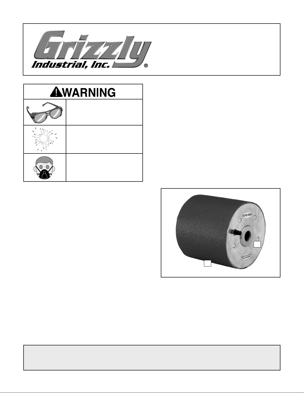
A. Pneumatic Sanding Drum .......................... 1
B. Sanding Sleeve .......................................... 1
-
B
-
-
Figure 1. Model G1972.
A
Completely releasing the pressure decreases the
diameter of the drum so the sanding sleeve can
be removed and replaced.
COPYRIGHT © MARCH, 2008 BY GRIZZLY INDUSTRIAL, INC.
WARNING: NO PORTION OF THIS MANUAL MAY BE REPRODUCED IN ANY SHAPE
OR FORM WITHOUT THE WRITTEN APPROVAL OF GRIZZLY INDUSTRIAL, INC.
#JB10527 PRINTED IN TAIWAN
Page 2

Operation
MODEL REF PART # DESCRIPTION
G1970
1 P1970001 RUBBER DRUM 3"
2 P1970002 VALVE STEM
3 PFH08 FLAT HD SCR 10-24 X 1/2
4 P1970004 10 PSI MAX. LABEL
5 P1970005
AIR COMPRESSOR LABEL
G1971
1 P1971001 RUBBER DRUM 4"
2 P1971002 VALVE STEM
3 PFH08 FLAT HD SCR 10-24 X 1/2
4 P1970004 10 PSI MAX. LABEL
5 P1970005
AIR COMPRESSOR LABEL
G1972
1 P1972001 RUBBER DRUM 6"
2 P1972002 VALVE STEM
3 PFH08 FLAT HD SCR 10-24 X 1/2
4 P1970004 10 PSI MAX. LABEL
5 P1970005
AIR COMPRESSOR LABEL
1. DISCONNECT BUFFER FROM POWER!
2. Install the sanding drum on the buffer shaft
using the spacers and flanges included with
the buffer (Figure 2
Buffer Shaft
Figure 2. Mounting drum to shaft.
).
Sanding Drum
Buffer Mounting
Hardware
Replacement Sanding Sleeves
G1973 3" x 6" x 100 Grit Silicon Carbide
G1974
G1975
G1976
G1977
G1978
3" x 6" x 150 Grit Silicon Carbide
4" x 6" x 100 Grit Silicon Carbide
4" x 6" x 150 Grit Silicon Carbide
6" x 6" x 100 Grit Silicon Carbide
6" x 6" x 150 Grit Silicon Carbide
Parts Breakdown & List
4
1
3
3. Slide the sanding sleeve over the sanding
drum.
4. Use a bicycle pump (or other manual pump)
to inflate the drum until the sanding sleeve is
secure. Do not exceed the 10 PSI maximum
rating.
EXPLOSION HAZARD!
Do not use an air compressor
to inflate the sanding drum!
Over-inflation will cause the
bladder to explode, resulting
in personal injury and/or tool
damage
Operation Tips
• Adjust the pressure in the drum to fine-tune
its firmness for sanding contours.
2
5
If you need help with your new pneumatic tool,
call our Tech Support at: (570) 546-9663.
• Always hold the workpiece firmly—the soft
surface of the drum will exert more force
on the workpiece than a traditional sanding
drum.
• Deflate the drum when not in use.
-2-
G1970/G1971/G1972 Pneumatic Sanding Drum
 Loading...