


DRILL PRESS
MODEL G1199/G1200
INSTRUCTION MANUAL
COPYRIGHT © 1990 BY GRIZZLY IMPORTS, INC. REG. #3176563
WARNING: NO PORTION OF THIS MANUAL MAY BE REPRODUCED IN ANY SHAPE
OR FORM WITHOUT THE WRITTEN APPROVAL OF GRIZZLY IMPORTS, INC.
REVISED JUNE, 1996 PRINTED IN USA
DISCONTINUED MACHINE MANUAL DISCLAIMER
THE INFORMATION IN THIS MANUAL REPRESENTS THE LAST CONFIGURATION OF THE MACHINE BEFORE IT WAS DISCONTINUED. MACHINE CON-
FIGURATIONS MAY HAVE CHANGED AS PRODUCT IMPROVEMENTS WERE INCORPORATED. IF YOU OWN AN EARLIER VERSION OF THE MACHINE,
THIS MANUAL MAY NOT EXACTLY DEPICT YOUR MACHINE . CONTACT CUSTOMER SERVICE IF YOU HAVE ANY QUESTIONS ABOUT DIFFERENCES.
PREVIOUS VERSIONS ARE NOT AVAILABLE ONLINE.

-B- G1199/G1200 Drill Press
WARNING
Some dust created by power sanding, sawing, grinding, drilling, and other construction activities contains
chemicals known to the State of California to cause
cancer, birth defects or other reproductive harm.
Some examples of these chemicals are:
• Lead from lead-based paints.
• Crystalline silica from bricks, cement, and
other masonry products.
• Arsenic and chromium from chemically treated
lumber.
Your risk from these exposures varies, depending on
how often you do this type of work. To reduce your
exposure to these chemicals: work in a well ventilated
area, and work with approved safety equipment, such
as those dust masks that are specially designed to filter out microscopic particles.

Table Of Contents
PAGE
1. INTRODUCTION ........................................................................................................2
SAFETY RULES FOR ALL TOOLS ........................................................................3
UNPACKING............................................................................................................4
PIECE INVENTORY ................................................................................................4
CLEAN UP ..............................................................................................................5
SITE CONSIDERATIONS ......................................................................................5
CIRCUIT REQUIREMENTS ..................................................................................6
2. ASSEMBLY .............................................................................................................. 7
BEGINNING ASSEMBLY ........................................................................................7
BASE/COLUMN....................................................................................................7-8
TABLE......................................................................................................................9
HANDLES ................................................................................................................9
DRILL CHUCK ......................................................................................................10
3. ADJUSTMENTS...................................................................................................... 11
SPEED CHANGE ..................................................................................................11
SPINDLE ADJUSTMENT ......................................................................................12
TABLE ADJUSTMENT ....................................................................................12-13
CHUCK REMOVAL ..............................................................................................13
4. OPERATIONS ........................................................................................................ 14
DRILL PRESS SAFETY RULES ..........................................................................14
TEST RUN ............................................................................................................15
DRILL CHANGES..................................................................................................15
DRILL SPEED ......................................................................................................16
DRILLING METAL ................................................................................................16
DRILLING WOOD..................................................................................................17
MORTISING ATTACHMENT ................................................................................17
5. MAINTENANCE........................................................................................................18
GENERAL..............................................................................................................18
BELT TENSION ....................................................................................................18
LUBRICATION ......................................................................................................18
6. CLOSURE ................................................................................................................19
PART BREAKDOWN ............................................................................................20
PART LISTS ..........................................................................................................21
MACHINE DATA....................................................................................................22
TROUBLESHOOTING ..........................................................................................23
WARRANTY AND RETURNS ..............................................................................24
R.P.M. CHART ......................................................................................................25
G1199/G1200 Drill Press -1-

-2- G1199/G1200 Drill Press
Grizzly Imports, Inc. is proud to offer the Model
G1199/G1200 Drill Press. This drill press is a part
of Grizzly’s growing family of fine woodworking
and metalworking machinery. When used according to the guidelines stated in this manual, you
can expect years of trouble-free, enjoyable operation.
The Model G1199/G1200 is intended for home
and medium-duty professional use. This drill
press features a 1,725 R.P.M.,
1
⁄2 H.P. capacitorstart motor, mechanical ON/OFF switch and a
cast iron working table.
All running parts utilize shielded ball bearings,
which require no lubrication for the life of the
bearings.
We are also pleased to provide this manual with
the Model G1199/G1200. It was written to guide
you through assembly, review safety considerations, and cover general operating procedures. It
represents our latest effort to produce the best
documentation possible. If you have any criticisms that you feel we should pay attention to in
our next printing, please write to us at the
Bellingham, WA address at the end of this section.
SECTION 1: INTRODUCTION
Most importantly, we stand behind our machines.
We have two excellent regional service departments at your disposal should the need arise. If
you have any service questions or parts requests,
please call or write to us at the appropriate location listed below.
If you live East of the Mississippi, contact:
Grizzly Industrial, Inc.
1203 Lycoming Mall Circle
Muncy, PA 17756
Phone:(570) 546-9663
Fax:(800) 438-5901
E-Mail: techsupport@grizzly.com
Web Site: http://www.grizzly.com
If you live West of the Mississippi, contact:
Grizzly Industrial, Inc.
P.O. Box 2069
Bellingham, WA 98227
Phone: (360) 647-0801
Fax: (800) 225-0021
E-Mail: Grizzlytec@aol.com
To operate this or any power tool safely and efficiently, it is essential to become as familiar with it
as possible. The time you invest before you begin
to use your Model G1199/G1200 will be time well
spent. DO NOT operate this machine until you
are completely familiar with the contents of this
manual.

G1199/G1200 Drill Press -3-
12. USE SAFETY GLASSES AND EAR PROTECTION. Also use a DUST MASK if the
operation is dusty.
13. DO NOT OVERREACH. Keep proper footing
and balance at all times.
14. MAINTAIN TOOLS IN TOP CONDITION.
Keep tools sharp and clean for best and
safest performance. Follow instructions for
lubricating and changing accessories.
15. DISCONNECT TOOLS FROM POWER
before servicing and when changing accessories.
16. AVOID ACCIDENTAL STARTING. Make
sure the switch is in the “OFF” position
before plugging in the cord.
17. CHECK DAMAGED PARTS. Do not operate
the machine until you are certain it is in perfect running condition.
18. NEVER LEAVE THE TOOL RUNNING
UNATTENDED - TURN POWER OFF. Do
not leave the tool until it comes to a full stop.
19. DO NOT OPERATE THE TOOL IF USING
DRUGS, ALCOHOL, OR MEDICATION.
20. DO NOT WORK IN HASTE or operate
machine if you are fatigued.
21. IF THERE IS SOMETHING YOU DO
NOT KNOW OR UNDERSTAND
ABOUT THIS TOOL, DO NOT OPERATE IT! Ask for help first. Confusion
can lead to disaster.
22. BAD HABITS ARE DANGEROUS. Review
all safety procedures often.
These safety rules cannot cover every situation in
a woodshop. Consider your conditions when setting up or operating your drill press.
1. KNOW YOUR POWER TOOL. Read the
owner’s manual carefully. Learn the tool’s
applications and limitations, as well as its
particular hazards.
2. KEEP ALL GUARDS IN PLACE and in
working order.
3. GROUND ALL TOOLS. If an adapter is
used to accommodate a two-prong receptacle, the adapter plug must be attached to a
known ground. Never remove the grounding
prong.
4. REMOVE ADJUSTING KEYS AND
WRENCHES. Make it a habit to check that
keys and wrenches are removed from the
machine before turning it on.
5. KEEP WORK AREA CLEAN. Cluttered
areas and benches invite accidents.
6. AVOID DANGEROUS ENVIRONMENTS.
Do not use power tools in damp or wet locations or expose them to rain. Keep your work
area well lighted.
7. KEEP CHILDREN AND VISITORS AWAY.
All children and visitors should be kept a safe
distance away from your work area.
8. MAKE WORKSHOP CHILD-PROOF with
padlocks, master switches, or by removable
starter keys.
9. DO NOT FORCE TOOL. Tools work better
and safer when they are allowed to perform
at their own speed.
10. WEAR PROPER APPAREL. Do not wear
loose clothing, gloves, neckties, or jewelry
that can get caught in moving parts. Non-slip
footwear must be worn. Long hair should be
tied back or wear a hat.
11. NEVER STAND ON, OR LEAN ON THE
TOOL. Doing so could cause injury.
Safety Rules For All Tools
G1199/G1200 Drill Press-4-
Unpacking
The Model G1199/G1200 Drill press is shipped
from the manufacturer in a carefully packed carton. If you discover the machine is damaged after
you’ve signed for delivery, please call Customer
Service immediately for advice.
Save the containers and all packing materials for
possible inspection by the carrier or its agent.
Otherwise filing a freight claim can be difficult.
Caution: The G1199/G1200 is a heavy machine
(G1199-140 lbs. shipping weight; G1200-150 lbs.
shipping weight). DO NOT over-exert yourself
while unpacking or moving your machine – get
assistance. In the event that your drill press must
be moved up or down a flight of stairs, be sure
that the stairs are capable of supporting the combined weight of people and the machine.
When you are completely satisfied with the condition of your shipment, you should inventory its
parts.
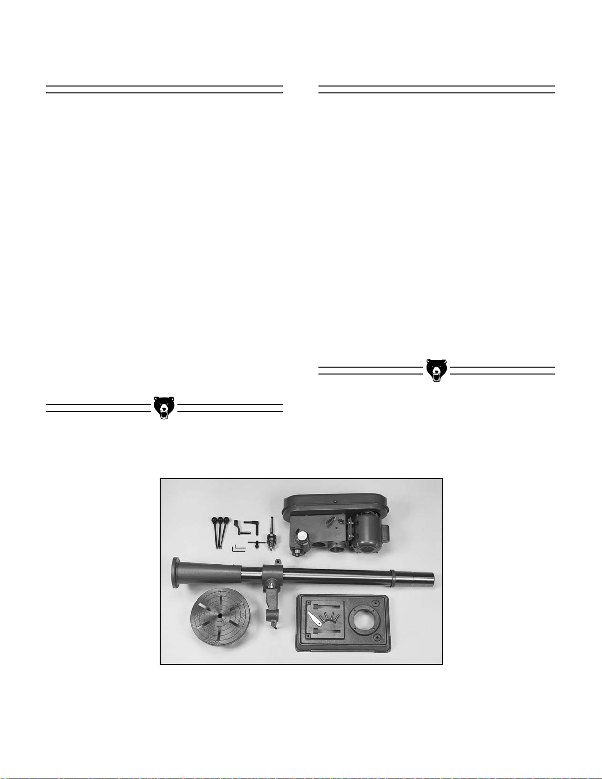
Piece Inventory
After all the parts have been removed from the
carton, you should have:
• Working Table
• Column
• Base
• Head Stock Assembly
• Drill Chuck and Arbor
• Crank Handle
• Column Lock Handle
• Handle Bar (3)
• Hex Bolt M10 - 1.5 x 40mm (4)
• Wedge Shifter
• Chuck Key
• 3 & 4mm Allen Wrenches
In the event that any non proprietary parts are
missing (e.g. a nut or a washer...), we would be
glad to replace them, or, for the sake of expediency, replacements can be obtained at your local
hardware store.
Figure 1. Overview of all the parts.
G1199/G1200 Drill Press -5-
Clean up
The column and other unpainted parts of the
Model G1199/G1200 are coated with a waxy oil
that protects them from corrosion during shipment. Remove the protective coating with mineral spirits and paper towels. Do not use gasoline or
other petroleum based solvents because of their
extremely low flash points. Do not use chlorinebased solvents – if you happen to splash some
onto a painted surface, you’ll ruin the finish.
WARNING!
Follow the safety rules listed below when
working with solvents:
1. Read and follow all directions and warnings
on the solvent label.
2. Work only in a well ventilated area.
3. Do not work near any type of open flame
(e.g., pilot lights, kerosene heaters, and so
on).
4. DO NOT smoke while working with flamma-
ble material.
5. Paper towels from the cleaning process are
extremely combustible. Dispose of waste
towels so they do not create a fire hazard.
Site Considerations
1. Floor Load: Your G1199/G1200 Drill press
represents a large weight load in a small
footprint. Most commercial floors are suitable
for the Model G1199/G1200. Some residential floors may require additional build up to
support both machine and operator.
2. Working Clearances: Consider existing and
anticipated needs, size of material to be
processed through each machine, and
space for auxiliary stands, work tables or
other machinery when establishing a home
for your drill press. Allow sufficient room to
safely run your machines in any foreseeable
operation.
3. Lighting and Outlets: Lighting should be
bright enough to eliminate shadow and prevent eye strain. Electrical circuits should be
dedicated or large enough to handle amperage requirements. Outlets should be located
near each machine so power or extension
cords are clear of high-traffic areas. Observe
local electrical codes for proper installation
of new lighting, outlets, or circuits.

-6- G1199/G1200 Drill Press
Circuit Requirements
The motor supplied with the G1199/G1200 is a
110V single-voltage motor, prewired for 110V.
Under normal use, the motor draws approximately 9 amps @ 110V. We recommend using a 15
amp circuit breaker or a 15 amp slow blow fuse
for 110V operation. This should be satisfactory
for normal use, while preventing motor damage
from high heat caused by overload. If frequent
circuit failures occur when using the drill press,
contact our service department or your local electrical contractor. The Drill press cannot be wired
for 220V operation.
This equipment must be grounded. Please
ensure that the drill press is continuously grounded from the motor to the machine frame and then
to a known ground. Verify that any existing electrical outlet and circuit you intend to plug into is
actually grounded. If it is not, it will be necessary
to run a separate 12 A.W.G. copper grounding
wire from the outlet to a known ground. Under no
circumstances should the grounding pin from any
three-pronged plug be removed.
Extension Cords: If used, extension cords must
be rated Hard Service (grade S) or better.
Conductor size must be 14 A.W.G. for cords up to
50 feet in length. Your extension cord must also
contain a ground wire and plug pin. Always repair
or replace extension cords if they become damaged.
Light: Your Drill Press is equipped with a built-in
110/120V lamp socket located between the spindle and the column. Maximum bulb wattage is 60
watts. Always unplug machine before changing
bulb.
CAUTION: Be sure that your particular electrical
configuration complies with local and state codes.
The best way to ensure compliance is to check
with your local municipality or licensed electrician.
G1199/G1200 Drill Press -7-
Beginning Assembly
Most of the Drill Press has been pre-assembled
at the factory. The few remaining pieces should
go together quickly and easily. Assembly is
straight forward and with just a few tools you can
do the entire job quickly and easily. This manual
is written for the G1199/G1200 model. The only
difference between the two regarding assembly is
the length of the column.
CAUTION: All die-cut metal parts have a sharp
edge (called “flashing”) on them after they are
formed. This is removed at the factory.
Sometimes though, a bit of flashing might escape
inspection. Please examine the edges of all diecut metal parts before handling them.
Tools Required: Only a few common tools are
needed to assemble this machine. Specifically, a
14mm open end wrench, Phillips screwdriver and
3mm and 4mm Allen wrench.
SECTION 2: ASSEMBLY
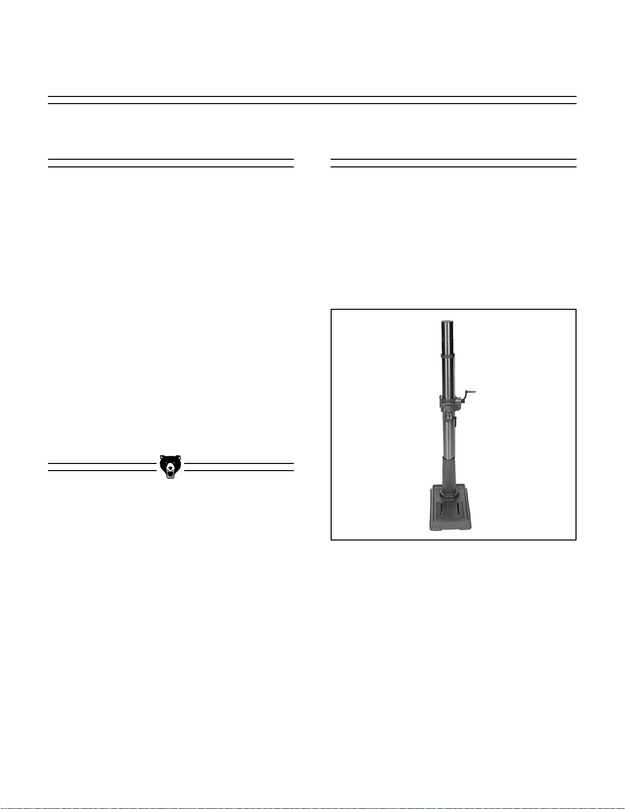
Figure 2. Base to column.
Base/Column
1. Place the base on the floor (if G1200) or on a
suitable bench (if G1199). In either case, be
sure the surface is flat and stable.
2. Place the column onto the base, line up the
four holes and secure tightly with the four
M10-1.5 x 40mm Hex Head Bolts provided.
Figure 2.

-8- G1199/G1200 Drill Press
Figure 4.
Figure 3. Worm pinion installed.
Figure 5.
3. Insert the worm pinion inside the table brack-
et and attach the crank handle by tightening
the setscrew. Figure 3.
4. The rack has a section on each end with no
teeth. The end with the larger blank section is
the top. Place the rack in the slot in the table
bracket with the top facing up. Position it so
the teeth mesh with the worm pinion. While
holding it in that position, slide the table bracket and rack down the column until the bottom
of the rack meets the base of the column.
Figure 4. The bevel in the rack should fit into
the bevel in the top of the base.
5. Slide the rack ring down the column until it fits
over the beveled section at the top of the rack.
Tighten the setscrew in the rack ring leaving
enough slack between the rack and the rack
ring to allow the rack to move freely around
the column. Figure 5. Do not over-tighten or
you may crack the rack ring casting.
6. Place the head assembly onto the top of the
column and lower it until it sits on the shoulder
machined into the top of the column.
CAUTION: The head assembly is quite
heavy; get assistance when lifting.
7. Secure the head to the column by tightening
the 5mm setscrews Figure 5.
worm pinion

G1199/G1200 Drill Press -9-
Figure 6. Installing the table.
2. Turn the crank handle to be sure the worm
pinion engages the teeth on the rack and
moves the bracket up and down. Figure 7.
CAUTION: Never use the drill press with
either table lock loose.
1. Place the table into the hole in the table bracket and secure with the handle. Figure 6.
Table
Screw the three handle bars into the tapped holes
in the handle body. Figure 8.
HHAANNDDLLEESS
Figure 8. Handles installed.
Figure 7.

-10- G1199/G1200 Drill Press
Drill Chuck
Figure 9. Drill chuck assembly.
The Drill Press chuck and arbor must be mounted in the drill press spindle. The arbor has a #6
Jacobs Taper on one end and a #2 Morse Taper
on the other. The #6 Jacobs Taper fits into the
drill chuck and the #2 Morse Taper fits in the drill
press spindle. The arbor, drill chuck and drill
press spindle fit together by friction fit. To mount
the drill chuck on the drill press:
1. Thoroughly clean all of the shipping oil or cos-
molene from both ends of the arbor, inside the
drill chuck and the drill press spindle. Use
mineral spirits and a rag.
2. Slide the arbor into the drill chuck and tap
lightly with a soft hammer or block of wood.
3. Slide the arbor and chuck into the drill press
spindle and turn it until the tang slips into the
slot in the spindle.
4. While holding onto the drill chuck, tap lightly
on the bottom of the chuck with a soft hammer
or a block of wood. The drill chuck should now
be quite snug in the drill press. If not, repeat
steps 1-3, making sure all oil or cosmolene is
removed.
Tang

G1199/G1200 Drill Press -11-
Speed Change
SECTION 3: ADJUSTMENTS
Remember to disconnect the drill press from the
power source before attempting any adjustments.
1. To change speed, loosen the two lock knobs,
one on either side of the head. Figure 10.
2. Turn the cam lever so the motor pulley moves
toward the center pulley. Figure 10.
3. Select the proper speed by referring to the
chart inside the pulley cover. Move the belts
into the corresponding position for the select-
ed speed. Figure 11.
4. Rotate the cam lever so the motor pulley
moves away from the center pulley and tightens the belt.
5. While holding tension on the cam lever, tight-
en the locking screws on both sides of the
head.
6. Close the cover. CAUTION: Never run the
drill press with the cover open.
NOTE: The speed chart under the pulley cover
reflects two different power cycles for the motor.
Use the 60 cycles per second spindle R.P.M. reference in the U.S.A.
Figure 10.
Figure 11.

-12- G1199/G1200 Drill Press
To stop the vertical travel of the drill bit at a
desired depth, loosen the scale set knob located
on the feed shaft assembly, rotate the handles to
the desired depth and tighten the scale set knob.
Figure 12.
To hold a stationary depth, loosen the scale set
knob and rotate the feed shaft to its lowest point.
Then, rotate spindle depth to the desired depth
and tighten the scale set knob. This will lock the
spindle at the desired depth.
Figure 12.
scale set knob
Spindle Adjustments
Table Adjustments
1. To adjust the table up or down, loosen the col-
umn lock handle and turn the crank handle to
the desired height. Re-tighten the column lock
handle. Figure 13.
2. To swing the table, loosen the column lock
handle and swing the table to the desired
position. Re-tighten the column lock handle.
For long workpieces, swing the work table
away 180° and use the base as your table.
Figure 13.
3. To rotate the table, loosen the table lock han-
dle, rotate the table to the desired position
and re-tighten the table lock handle. Figure
14.
Figure 13.
lock handle

G1199/G1200 Drill Press -13-
Figure 15.
Figure 14.
4. To tilt the table, loosen the pivot bolt and
remove the locator pin (Figure 15). This is
done by tightening the nut until the pin is
extracted from its hole. Tilt the table to the
desired angle (up to 45°) and re-tighten the
pivot bolt. Re-insert the locator pin when
returning the table to zero degrees.
1. Adjust the stationary depth to three inches
(see depth setting instructions).
2. Rotate the spindle manually and line up the
internal spindle slot with the slot on the side of
the quill. The end of the drill chuck (the tang)
should be visible through the slot at this point.
3. Insert the wedge shifter through the slot in the
spindle with the tapered edge facing down.
Figure 16.
4. When the tapered edge of the wedge shifter
contacts the top of the taper, tap the wedge
shifter lightly with a hammer until the taper
and chuck are loose. Do not allow the taper
and chuck to fall onto the table.
Figure 16. Removing the chuck.
Chuck Removal

-14- G1199/G1200 Drill Press
Caution
Always wear ANSI-approved safety
glasses or goggles when operating
equipment — particularly when testing new tools or machinery. Do not
allow visitors into your workshop
when testing or operating equipment.
SECTION 4: OPERATIONS
Safety Rules
• The workpiece must be held securely in place
using a drill press vise or clamp.
• Never use a bit with a tapered shank or
square bit in a drill chuck.
• Use the correct speed for the size of bit and
material being drilled.
• Always remove the key from the chuck before
starting drill press.
• Remove metal cuttings with a brush, never by
hand.
• Perform machine inspection and maintenance
service routinely.
• Never drill sheet metal unless it is securely
clamped to the table.
• Work should be secured in such a way so as
to avoid drilling into the table.
• When changing speeds, always disconnect
the machine from the power source.
This sums up our review of safety guidelines.
Remember that every shop has its own specific
hazards. Be sure, above all else, to use good
common sense and reasonable caution each
time you start this drill press, or any woodworking
machinery. Proper safety standards rarely take
any more time or energy when followed religiously. Develop a habit of safety.
Now that your drill press is assembled and in
place, you are ready to begin using it. Your new
drill press is a simple piece of equipment to set up
and operate. It is a versatile tool that can be used
to perform many different operations such as:
Drilling, Boring, Sanding, Mortising and Shaping.
For your own protection, please read and follow
these safety precautions.
•While operating this machine, do not wear
jewelry, loose clothing, necklaces or neckties.
Long sleeves on shirts should be rolled up or
securely buttoned at the cuff.
• Persons with beards and/or long hair should
consider the use of a hat, hair net or similar
protective equipment.
• Always use face/eye protection when operating the drill press. A full face shield will afford
the best protection followed by safety glasses
with side shields.
• All adjustments or maintenance should be
done with the power off and the drill press
unplugged.
• Never use tools that are in poor condition.
Cutting tools that are dull or damaged are difficult to control and may cause serious injury.
• Thoroughly clean the machine and surrounding area after use.
• Feed the drill bit evenly into the workpiece.
Back the bit out of deep cuts to cool and clean
the bit.
• If you have questions about your drill press,
ask a professional or an experienced user.
• Never attempt to clean wood or metal cuttings
from drill bits while the drill press is running.

G1199/G1200 Drill Press -15-
Once the assembly is complete and the adjustments are done to your satisfaction, you are
ready to test the machine.
Turn on the power supply at the main panel.
Press the START button. Make sure that your finger is poised on the STOP button, just in case
there’s a problem. The drill press should run
smoothly, with little or no vibration or rubbing
noises. Strange or unnatural noises should be
investigated and corrected before operating the
machine further.
WARNING: DO NOT attempt to investigate or
adjust the machine while it is running. Wait until
the machine is turned off, unplugged and all
working parts have come to a rest before you do
anything!
If noises occur that can not be found by visual
inspection, feel free to contact our service
department for help.
Test Run Drill Changes
Figure 17.
To insert or change a bit, care must be taken to
secure the bit firmly in place. When changing bits,
proceed as follows:
1. Disconnect the machine from the power
source.
2. Open the chuck wide enough to accept a new
bit.
3. Install the bit so the chuck jaws will grab the
major portion of the bit shank. Do not allow
the chuck to grab the fluted body of the drill
bit.
4. Tighten the chuck with the chuck key using all
three key locations.
5. Remove the chuck key and reconnect to the
power source.
6. Reverse steps to remove drill bit.

-16- G1199/G1200 Drill Press
Drilling Metal
When drilling metal, use clamps to hold the workpiece securely in place. The workpiece should
never be held in place by bare hands. The cutting
edge can catch in the material at any time, resulting in serious injury. Any movement of the workpiece during the drilling operation may result in a
rough or misplaced hole and increase the chance
of drill bit breakage.
For flat work, lay the workpiece on a wooden
base and clamp it firmly to the table. Use a Vblock and clamp for round stock. A drill press vise
with prismatic jaws can also be used to hold flat
or round material.
Drill Speed
The best speed to use in any drill press operation
is determined by; material, size of drill bit, type of
drill bit or cutter and quality of cut desired. The
smaller the drill bit, the greater the speed. In soft
materials, the speed should be higher than for
hard materials. Refer to the chart on Page 25.

G1199/G1200 Drill Press -17-
Figure 18. Mortise Attachment installed.
Mortise Attachment
The optional Grizzly G1083 Mortise Attachment
was specifically designed to fit the G1199/G1200
Drill Presses. Refer to our current catalog for
ordering information.
Drilling Wood
Twist bits, which are intended for metal, may also
be used for boring holes in wood. Machine spur
bits are generally preferred, they cut a square
bottomed hole and are designed for removal of
wood chips. Do not use hand bits which have a
screw tip; at drill press speeds they turn into the
wood too fast and tend to lift the workpiece off the
table and spin it.
For through boring, line up the hole in the work
table with the bit to avoid damaging its tip. Scribe
a vertical line on the column and a matching line
on the table bracket so the table can be clamped
in the center position at any height. Use a piece
of scrap wood under your workpiece and feed the
bit into the wood slowly to prevent splintering the
bottom side of the workpiece.
When using your drill press for operations such
as shaping, sanding or mortising, use jigs, fixtures or hold-downs that are appropriate. For
more information, review reference materials pertaining to your specific application.
The chuck will accept any tool with up to a
5
⁄8"
shank. Do not attempt to open the chuck wider by
forcing it.

-18- G1199/G1200 Drill Press
SECTION 5: MAINTENANCE
Lubrication
Belt Tension
Shielded and pre-lubricated ball bearings require
no lubrication for the life of the bearings. In a continuous-use environment, expect the bearings to
last for several years. With intermittent use, bearings can be expected to last much longer. All
bearings are standard sizes and can be easily
replaced.
For other items on this machine, such as the quill,
table and column, an occasional shot of light
machine oil is all that is necessary. Before applying lubricant, clean off sawdust and metal chips.
Use a light grease on the rack, both on the teeth
and between the rack and column.
Your goal is to achieve adequate lubrication. Too
much lubricant will attract dirt and sawdust and
clog the drill press mechanism.
Proper belt tension is achieved by tightening the
belt adjusting cam so the belt has a slight tension
on it. Excessive tension will create heat and
shorten belt life. Too little tension will cause the
belt to slip and squeal.
Make a habit of inspecting your drill press each
time you use it. Check for the following conditions
and repair or replace when necessary.
1. Loose mounting bolts.
2. Worn switch.
3. Worn or damaged cords and plugs.
4. Damaged V-belt.
5. Any other condition that could hamper the
safe operation of this machine.
General

G1199/G1200 Drill Press -19-
The following pages contain parts diagram, parts
list, general machine data, trouble shooting guide
and Warranty/Return information for your Model
G1199/G1200 Drill Press.
If you need parts or help in assembling your
machine, or if you need operational information,
we encourage you to call the appropriate regional Service Department. Our trained service technicians will be glad to help you.
If you have comments dealing specifically with
this manual, please write to our Bellingham,
Washington location using the address in the
Introduction. The specifications, drawings, and
photographs illustrated in this manual represent
the Model G1199/G1200 as supplied when the
manual was prepared. However, due to Grizzly’s
policy of continuous improvement, changes may
be made at any time with no obligation on the part
of Grizzly. Whenever possible, though, we send
manual updates to all owners of a particular tool
or machine. Should you receive one, add the new
information to this manual and keep it for reference.
We have included some important safety measures that are essential to this machine’s operation. While most safety measures are generally
universal, Grizzly reminds you that each workshop is different and safety rules should be con-
sidered as they apply to your specific situation.
We recommend you keep a copy of our current
catalog for complete information regarding
Grizzly's warranty and return policy. If you need
additional technical information relating to this
machine, or if you need general assistance or
replacement parts, please contact the appropriate regional Service Department listed in the
introduction.
Additional information sources are necessary to
realize the full potential of this machine. Trade
journals, woodworking magazines, and your local
library are good places to start.
WARNING!
Like all power tools, there is danger associated
with the Model G1199/G1200 Drill press. Use the
tool with respect and caution to lessen the possibility of mechanical damage or operator injury. If
normal safety precautions are overlooked or
ignored, injury to the operator or others in the
area is likely.
The Model G1199/G1200 was specifically
designed for drilling operations. DO NOT MODI-
FY AND/OR USE THIS DRILL PRESS FOR
ANY OTHER PURPOSE. Modifications or
improper use of this tool will void the warranty. If you are confused about any aspect of this
machine, DO NOT use it until you have answered
all your questions.
SECTION 6: CLOSURE

1
2
3
5
4
22
12
20
15
14
13
16
21
17
18
6
19
7
8
9
11
10
46
48
37
43
45
44
42
41
38
29
100
30
31
24
23
82
26
33
26
78
77
74
76
75
35
34
36
79
81
80
99
90
92
91
93
99
69
70
65
68
66
67
66
68
86
89
88
87
54
55
51
49
53
64
63
62
57
56
59
58
71
72
73
61
25
48
47
84
83
28
27
85
95
96
98
32B
32A
39
52
-20- G1199/G1200 Drill Press

G1199/G1200 Drill Press -21-
1 P1199001 BASE
2 P1199002 COLUMN HOLDER
4 P1199004 COLUMN
5 PB31M HEX BOLT M10-1.5 X 40
6 P1199006 BRACKET
7 P1199007 PINION GEAR
8 P1199008 GEAR SHAFT
9 P1199009 WORM PINION
10 P1199010 CRANK HANDLE
11 PSS01M SETSCREW M6-1.0 X 10
12 P1199012 TABLE BRACKET
13 P1199013 SPECIAL HEX BOLT
14 P1199014 LOCATOR PIN
15 PN05 HEX NUT
1
⁄4''-20
16 P1199016 ANGLE SCALE
17 P1199017 CENTERING SCALE
18 P1183108 RIVET
19 P1199019 COLUMN LOCK HANDLE
20 P1199020 TABLE LOCK HANDLE
21 P1199021 TABLE
22 P4008022 RACK
23 P4008023 RACK RING
24 PSS03M SET SCREW M6-1.0 X 8
25 P1199025 HEAD CASTING
26 PSS13M SET SCREW M10-1.5 X 12
27 P1199027 LAMP SOCKET
28 PB02M HEX BOLT M6-1.0 X 12
29 P1199029 CAM HANDLE
30 P1199030 CAM
31 PB03M HEX BOLT M8-1.25 X 16
32A P1199032A SLIDE BAR
32B P1199032B CAM SLIDE BAR
33 P1199033 LOCK KNOB
34 P1199034 MOTOR BASE
35 PLW05M LOCK WASHER 12MM
36 PN09M HEX NUT M12-1.75
37 P1199037 HANDLE BODY
38 P1199038 FEED SHAFT
39 PRP24M ROLL PIN 5 X 16
41 P1199041 SCALE GUIDE
42 P1199042 SCALE SET HANDLE
43 P1199043 HANDLE BAR
44 P1199044 KNOB
45 P1199045 SPINDLE DEPTH
46 P1199046 SCALE
47 P1199047 CENTERING SCALE
48 P1183108 RIVET
49 P1199049 SPRING & HOUSING
51 P1199051 SPRING SEAT
51A P1199051A SPRING SEAT BUSHING
52 P1199052 SPECIAL SET SCREW
53 PN01 HEX NUT
1
⁄2''-20
54 P1199054 SPECIAL SET SCREW
55 PN02M HEX NUT M10-1.5
56 P1199056 QUILL
57 P1199057 RUBBER WASHER
58 P1199058 SPINDLE SHAFT
59 P6205 BEARING 6205-2RS
60 P1199060 NAME PLATE
61 P6203 BEARING 6203-2RS
62 P1199062 SPECIAL WASHER
63 P1199063 SPECIAL LOCK NUT
64 P1199064 SPECIAL NUT
65 P1199065 DRIVE SLEEVE
66 P6205 BEARING 6205-2RS
67 P1199067 COLLAR
68 P1199068 SPECIAL SNAP RING
69 PN10M HEX NUT M25-1.5 L.H.
70 P1199070 SPINDLE PULLEY
71 G1676 ARBOR
72 G1650 CHUCK,
5
⁄8''
72A P1199072A
5
⁄8'' CHUCK KEY
73 P1199073 WEDGE SHIFTER
74 P1199074 MOTOR
75 P1199075 MOTOR CORD
76 PB09M HEX BOLT M8-1.25 X 20
77 PW01M FLAT WASHER 8MM
78 PN03M HEX NUT M8-1.25
79 P1199079 MOTOR PULLEY
80 PK24M KEY 5 X 5 X 37
81 PSS01M SET SCREW M6-1.0 X 10
82 P1199082 WIRE INSULATOR
83 P1199083 WIRE CLIP
84 P1199084 CLIP SCREW
85 P1199085 CORD
86 P1199086 CLIP TERMINAL
87 P1199087 SWITCH
88 P1199088 SWITCH COVER
89 PS08M SCREW M5-0.8 X 12
90 P1199090 PULLEY COVER
91 PW03M FLAT WASHER
92 PS11M SCREW M6-1.0 X 16
93 P1199093 COVER KNOB
95 P1199095 CENTER PULLEY
96 P6202 BEARING 6205-2RS
98 P1199098 CENTER PULLEY SHAFT
99 PVM25 V-BELT M-25
100 P1199100 SNAP RING
--G1200 UNIQUE PARTS-01 P1200001 BASE
03 PSS13M SET SCREW M10-1.5 X 12
02 P1200002 COLUMN HOLDER
04 P1200004 COLUMN
22 P1200022 RACK
REF PART # DESCRIPTION REF PART # DESCRIPTION

-22- G1199/G1200 Drill Press
MACHINE DATA
GRIZZLY MODEL G1199 & G1200 DRILL PRESS
Design Type . . . . . . . . . . . . . . . . . . . . . . . . . . . . . . . . . . . . . . . . . . .Bench Model/Floor Model
Overall Dimensions
Table Size . . . . . . . . . . . . . . . . . . . . . . . . . . . . . . . . . . . . . . . . . . . . . . . . . . .12" Round
Height . . . . . . . . . . . . . . . . . . . . . . . . . . . . . . . . . . . . . . . . . . . . . . . . . . . . . . . . .40"/60"
Overall Width . . . . . . . . . . . . . . . . . . . . . . . . . . . . . . . . . . . . . . . . . . . . . . . . . . . . . .12"
Overall Depth . . . . . . . . . . . . . . . . . . . . . . . . . . . . . . . . . . . . . . . . . . . . . . . . . . . . . .25"
Shipping Weight . . . . . . . . . . . . . . . . . . . . . . . . . . . . . . . . . . . . . . . . . . . . .160/210 lbs.
Weight in Place . . . . . . . . . . . . . . . . . . . . . . . . . . . . . . . . . . . . . . . . . . . . . .150/200 lbs.
Construction
Table . . . . . . . . . . . . . . . . . . . . . . . . . . . . . . . . . . . . . . . . . .Precision Ground Cast Iron
Column . . . . . . . . . . . . . . . . . . . . . . . . . . . . . . . . . . . . . . . . .Precision Ground Cast Iron
Base & Head . . . . . . . . . . . . . . . . . . . . . . . . . . . . . . . . . . . . . . . . . . . . . . . . . .Cast Iron
Motor
Type . . . . . . . . . . . . . . . . . . . . . . . . . . . . . . . . . . . . . . . .TEFC Capacitor Start Induction
Horsepower . . . . . . . . . . . . . . . . . . . . . . . . . . . . . . . . . . . . . . . . . . . . . . . . . . . . .1⁄2" HP
Phase/Cycle . . . . . . . . . . . . . . . . . . . . . . . . . . . . . . . . . . . . . . . . . .Single Phase/60 Hz
Voltage . . . . . . . . . . . . . . . . . . . . . . . . . . . . . . . . . . . . . . . . . . . . . . . . . . . . . . . . .110V
Amps . . . . . . . . . . . . . . . . . . . . . . . . . . . . . . . . . . . . . . . . . . . . . . . . . . . . . . . . . . . . . .9
RPM . . . . . . . . . . . . . . . . . . . . . . . . . . . . . . . . . . . . . . . . . . . . . . . . . . . . . . .1725 RPM
Switch . . . . . . . . . . . . . . . . . . . . . . . . . . . . . . . . . . . . . . . . . . . . . . . . . . . . .Power/Light
Power Transfer . . . . . . . . . . . . . . . . . . . . . . . . . . . . . . . . . . . . . . . . . . . . . . . .Belt Drive
Bearings . . . . . . . . . . . . . . . . . . . . . . . . . . . . . .Shielded & Permanently Lubricated Ball
Capacities
Spindle Travel . . . . . . . . . . . . . . . . . . . . . . . . . . . . . . . . . . . . . . . . . . . . . . . . . . . . . . .3"
Maximum (Spindle to Base) . . . . . . . . . . . . . . . . . . . . . . . . . . . . . . . . . . . . . . . . .24"/49"
Maximum (Spindle to Table) . . . . . . . . . . . . . . . . . . . . . . . . . . . . . . . . . . . . . . . .16"/29"
Spindle Taper . . . . . . . . . . . . . . . . . . . . . . . . . . . . . . . . . . . . . . . . . . . . . . . . . . . .MT #2
Chuck Size . . . . . . . . . . . . . . . . . . . . . . . . . . . . . . . . . . . . . . . . . . . . . . . . . . . . . . . . .5⁄8"
Speeds . . . . . . . . . . . . . . . . . . . . . . . . . . . . . . . . . . . . . . . . . . . . . . . . . . . . . . . . . . . .12
Range of Speeds . . . . . . . . . . . . . . . . . . . . . . . . . . . . . . . . . . . . . . . . .250 - 3100 RPM
Features
• Built in light, 110V, 60 watt maximum
• Table tilts 90° left or right, swings 360°
• 4-step pulley, 2-step drive pulley
• Positive table lock
• Worm geared table adjustment
Specifications, while deemed accurate, are subject to change without notice.

G1199/G1200 Drill Press -23-
TROUBLESHOOTING
WARNING: For your own safety, turn the switch off and disconnect power source before troubleshooting.
Trouble
Probable Cause Remedy
Noisy operation 1. Incorrect belt tension 1. Adjust tension
2. Dry spindle 2. Lubricate spindle
See lubrication section
3. Loose spindle pulley or motor pulley 3. Tighten setscrews in pulley
Bit burns or smokes 1. Incorrect speed 1. Select correct speed
See speed chart
2. Chips clogging hole 2. Retract bit frequently
to clear chips
3. Dull bit 3. Sharpen or replace bit
4. Feeding too slow 4. Increase feed rate
5. Bit not lubricated 5. Lubricate bit
6. Bit running backwards 6. Check motor rotation
Excessive drill runout 1. Bent bit 1. Replace bit
or wobble 2. Worn spindle bearings 2. Replace bearings
3. Bit improperly installed in chuck 3. Install bit properly
4. Chuck improperly installed 4. Install chuck properly
Drill binds in workpiece 1. Workpiece pinching bit or excessive 1. Support or clamp
feed pressure workpiece,reduce feed pressure
2. Improper belt tension 2. Adjust belt tension
Workpiece torn loose Workpiece not supported or Support or clamp workpiece
from hand clamped properly

-24- G1199/G1200 Drill Press
Grizzly Imports, Inc. warrants every product it sells for a period of 1 year to the original purchaser from the
date of purchase. This warranty does not apply to defects due directly or indirectly to misuse, abuse, negligence, accidents, repairs or alterations or lack of maintenance. This is Grizzly’s sole written warranty and
any and all warranties that may be implied by law, including any merchantability or fitness, for any particular purpose, are hereby limited to the duration of this written warranty. We do not warrant or represent that
the merchandise complies with the provisions of any law or acts unless the manufacturer so warrants. In
no event shall Grizzly’s liability under this warranty exceed the purchase price paid for the product and any
legal actions brought against Grizzly shall be tried in the State of Washington, County of Whatcom.
We shall in no event be liable for death, injuries to persons or property or for incidental, contingent, special, or consequential damages arising from the use of our products.
To take advantage of this warranty, contact us by mail or phone and give us all the details. We will then
issue you a “Return Number’’, which must be clearly posted on the outside as well as the inside of the carton. We will not accept any item back without this number. Proof of purchase must accompany the merchandise.
The manufacturers reserve the right to change specifications at any time because they constantly strive to
achieve better quality equipment. We make every effort to ensure that our products meet high quality and
durability standards and we hope you never need to use this warranty.
Please feel free to write or call us if you have any questions about the machine or the manual.
Thank you again for your business and continued support. We hope to serve you again soon.
WARRANTY AND RETURNS

G1199/G1200 Drill Press -25-
Recommended RPM
Drill Cast
Diameter Iron Steel Aluminum Wood
1
⁄8" 1900 2620 2620 2620
3
⁄16" 1550 1620 2620 2620
1
⁄4" 990 1350 1550 2620
5
⁄16" 650 990 1550 1550
3
⁄8" 600 990 990 1550
7
⁄16" 510 650 990 990
1
⁄2" 510 650 650 990
9
⁄16" 390 600 650 990
5
⁄8" 390 510 510 650
3
⁄4" 340 390 510 350
7
⁄8" 250 340 390 510
1" — 340 390 510
11⁄8"—250 340 390
11⁄4"—— 340 390

D
C
B
A
4
3
2
1
4
3
2
1
RPM :250
BELT: A-1, 4-4
1
D
C
B
A
4
3
2
1
4
3
2
1
RPM : 510
BELT: B-2, 3-3
4
D
C
B
A
4
3
2
1
4
3
2
1
RPM : 990
BELT:D-4, 3-3
7
D
C
B
A
4
3
2
1
4
3
2
1
RPM : 1900
BELT: D-4, 2-2
10
D
C
B
A
4
3
2
1
4
3
2
1
RPM :340
BELT: A-1,3-3
2
D
C
B
A
4
3
2
1
4
3
2
1
RPM : 600
BELT: C-3, 4-4
5
D
C
B
A
4
3
2
1
4
3
2
1
RPM : 1550
BELT: C-3, 2-2
8
D
C
B
A
4
3
2
1
4
3
2
1
RPM : 2620
BELT: C-3, 1-1
11
D
C
B
A
4
3
2
1
4
3
2
1
RPM : 390
BELT: B-2, 4-4
3
D
C
B
A
4
3
2
1
4
3
2
1
RPM : 650
BELT: A-1, 2-2
6
D
C
B
A
4
3
2
1
4
3
2
1
RPM : 1620
BELT: B-2, 1-1
9
D
C
B
A
4
3
2
1
4
3
2
1
RPM : 3100
BELT:D-4, 1-1
12
-26- G1199/G1200 Drill Press

G1199/G1200 Drill Press -27-
NOTES:
 Loading...