

Grizzly G0825 Owner's Manual

MODEL G0825
PORTABLE EDGEBANDER
OWNER'S MANUAL
(For models manufactured since 02/17)
COPYRIGHT © AUGUST, 2017 BY GRIZZLY INDUSTRIAL, INC.
WARNING : NO PORTION OF THIS MANUAL MAY BE REPRODUCED IN ANY SHAPE
OR FORM WITHOUT THE WRITTEN APPROVAL OF GRIZZLY INDUSTRIAL, INC.
#JH18821 PRINTED IN TA I WAN
V1. 0 8.17

This manual provides critical safety instructions on the proper setup,
operation, maintenance, and service of this machine/tool. Save this
document, refer to it often, and use it to instruct other operators.
Failure to read, understand and follow the instructions in this manual
may result in fire or serious personal injury—including amputation,
electrocution, or death.
The owner of this machine/tool is solely responsible for its safe use.
This responsibility includes but is not limited to proper installation in
a safe environment, personnel training and usage authorization,
proper inspection and maintenance, manual availability and comprehension, application of safety devices, cutting/sanding/grinding tool
integrity, and the usage of personal protective equipment.
The manufacturer will not be held liable for injury or property damage
from negligence, improper training, machine modifications or misuse.
Some dust created by power sanding, sawing, grinding, drilling, and
other construction activities contains chemicals known to the State
of California to cause cancer, birth defects or other reproductive
harm. Some examples of these chemicals are:
• Lead from lead-based paints.
• Crystalline silica from bricks, cement and other masonry products.
• Arsenic and chromium from chemically-treated lumber.
Your risk from these exposures varies, depending on how often you
do this type of work. To reduce your exposure to these chemicals:
Work in a well ventilated area, and work with approved safety equipment, such as those dust masks that are specially designed to filter
out microscopic particles.

Table of Contents
INTRODUCTION ............................................................................................................................... 2
Contact Info ................................................................................................................................ 2
Manual Accuracy ........................................................................................................................ 2
Identification ............................................................................................................................... 3
Controls & Components ............................................................................................................. 4
SECTION 1: SAFETY ....................................................................................................................... 8
Safety Instructions for Machinery ............................................................................................... 8
Additional Safety for Edgebanders........................................................................................... 10
SECTION 2: POWER SUPPLY ...................................................................................................... 11
SECTION 3: SETUP ....................................................................................................................... 13
Unpacking ................................................................................................................................ 13
Needed for Setup ..................................................................................................................... 13
Inventory ................................................................................................................................... 13
Hardware Recognition Chart .................................................................................................... 14
Site Considerations .................................................................................................................. 15
Assembly .................................................................................................................................. 15
Test Run ................................................................................................................................... 16
SECTION 4: OPERATIONS ........................................................................................................... 17
Operation Overview.................................................................................................................. 17
Material Inspection & Edgebander Preparation ....................................................................... 18
Checking/Adding Glue.............................................................................................................. 18
Setting Infeed Guide ................................................................................................................ 19
Setting Guide Plate .................................................................................................................. 19
Performing Edgebanding Operations ....................................................................................... 21
Edgebanding Inside Corners .................................................................................................... 23
Adjusting Glue Amount ............................................................................................................ 24
Using Low Temperature Mode ................................................................................................. 25
Installing Table Mount .............................................................................................................. 26
SECTION 5: ACCESSORIES ......................................................................................................... 27
SECTION 6: MAINTENANCE......................................................................................................... 29
Schedule .................................................................................................................................. 29
Cleaning & Protecting .............................................................................................................. 29
Lubrication ................................................................................................................................ 29
SECTION 7: SERVICE ................................................................................................................... 30
Troubleshooting ........................................................................................................................ 30
SECTION 8: WIRING ...................................................................................................................... 32
Wiring Safety Instructions ........................................................................................................ 32
Wiring Schematic ..................................................................................................................... 33
SECTION 9: PARTS ....................................................................................................................... 33
Housing/Accessory Breakdown................................................................................................ 33
Internal Parts ............................................................................................................................ 35
Labels & Cosmetics ................................................................................................................. 37
WARRANTY & RETURNS ............................................................................................................. 40
We stand behind our machines! If you have questions or need help, contact us with the information
below. Before contacting, make sure you get the
serial number
machine ID label. This will help us help you faster.
We want your feedback on this manual. What did
you like about it? Where could it be improved?
Please take a few minutes to give us feedback.
Email: manuals@grizzly.com
We are proud to provide a high-quality owner’s
manual with your new machine!
We
instructions, specifications, drawings, and photographs
in this manual. Sometimes we make mistakes, but
our policy of continuous improvement also means
that
you receive is
slightly different than shown in the manual
If you find this to be the case, and the difference
between the manual and machine leaves you
confused or unsure about something
check our
website for an updated version. W
current
manuals and
on our web-
site at
Alternatively, you can call our Technical Support
for help. Before calling, make sure you write down
the
from
the machine ID label (see below). This information
is required for us to provide proper tech support,
and it helps us determine if updated documentation is available for your machine.
INTRODUCTION
Contact Info
and manufacture date from the
Grizzly Technical Support
1815 W. Battlefield
Springfield, MO 65807
Phone: (570) 546-9663
Email: techsupport@grizzly.com
Grizzly Documentation Manager
P.O. Box 2069
Bellingham, WA 98227-2069
Manual Accuracy
made every effort to be exact with the
sometimes the machine
.
,
e post
manual updates for free
www.grizzly.com.
Manufacture Date and Serial Number
Manufacture Date
Serial Number
-2-
Model G0825 (Mfd. Since 02/17)
Identification
To reduce your risk of
serious injury, read this
entire manual BEFORE
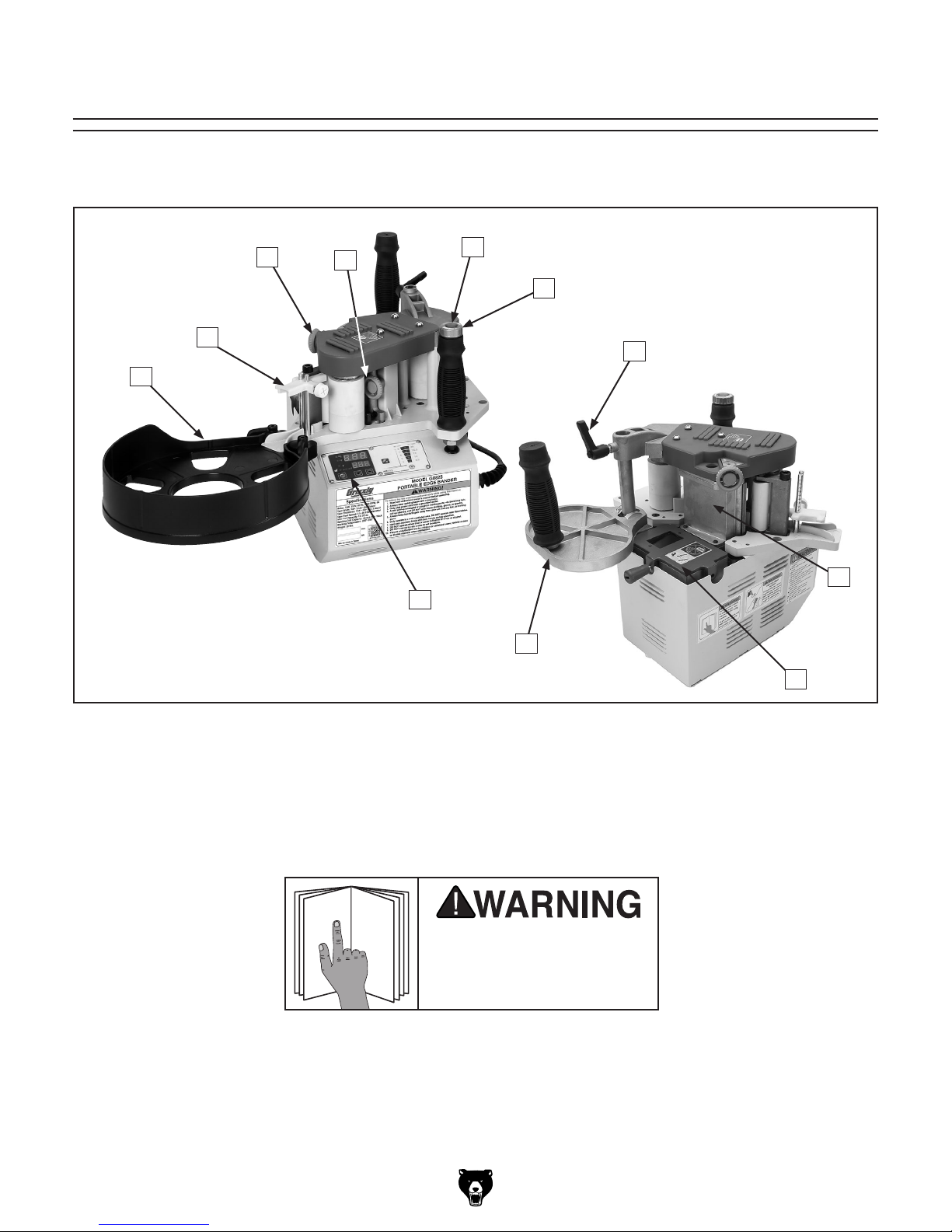
Become familiar with the names and locations of the controls and features shown below to better understand
the instructions in this manual.
C
B
A
D
K
E
F
G
H
J
I
A. Tape Dispenser
B. Infeed Guide Plate
C. Glue Dial
D. Tension Dial
E. Feed Roller ON/OFF Button
F. Feed Rate Dial
Model G0825 (Mfd. Since 02/17)
G. Guide Plate Lock
H. Heated Fence
I. Glue Pot
J. Guide Plate
K. Control Panel (see Figure 3 on Page 5)
using machine.
-3-
Controls &
To reduce your risk of
serious injury, read this
entire manual BEFORE
E. Master Power Switch: Allows power to
machine.
Components
using machine.
Refer to the following figures and descriptions to
become familiar with the basic controls and components of this machine. Understanding these
items and how they work will help you understand
the rest of the manual and minimize your risk of
injury when operating this machine.
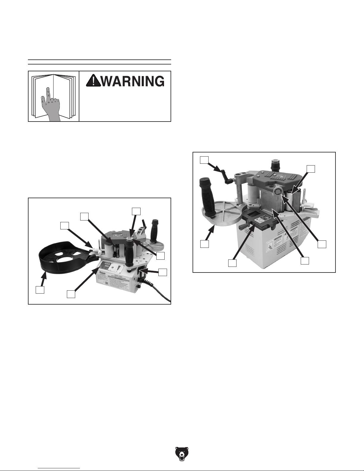
Component Descriptions
C
B
A
Note: Glue pot heater unit does not automati-
cally activate when Master Power Switch is
turned ON. Heating Unit ON/OFF Button (see
Page 5) must also be pressed to heat glue
pot.
F. Control Panel: Illuminates when Master
Power Switch is turned ON (see Page 5 for
detailed Control Panel functions).
G. Tape Dispenser: Holds edgebanding tape
rolls during operation.
H
I
D
E
G
Figure 1. Edgebander components (front).
A. Infeed Guide: Directs edgebanding tape
between feed roller and glue roller.
B. Tension Dial: Adjusts edgebanding tape ten-
sion to evenly distribute glue during operation.
C. Feed Roller ON/OFF Button: Turns feed
rollers ON once glue pot is heated. Feed
roller will not activate if glue pot temperature
is below 250°F (120°C).
F
M
L
Figure 2. Edgebander components (rear).
H. Guide Plate Lock: Secures guide plate
height for operation.
I. Feed Roller: Feeds edgebanding tape into
glue roller while applying pressure.
J. Glue Dial: Adjusts amount of glue applied to
edgebanding.
K. Heated Fence: Houses glue spindle and
edgebanding tape pressure plate.
L. Glue Pot Cover: Features a viewing window
to verify glue pot level. Unscrew lock handle
to refill glue.
J
K
D. Feed Rate Control Dial: Adjusts edgeband-
ing tape feed rate between 6.5–20 FPM.
-4-
M. Guide Plate: Adjusts to maintain even appli-
cation of edgebanding tape to workpiece.
Locks in place with guide plate lock (H).
Features handle for two-handed operation.
Model G0825 (Mfd. Since 02/17)

Control Panel
N
W
V
U
Figure 3. Control panel functions.
N. °C & °F Readout Indicator Lights: Indicate if
temperature is shown in Fahrenheit or Celsius.
Setting is adjusted using Temperature
Control Buttons (T).
O
P
T
S. Feed Roller Preheat Light: Illuminates when
glue pot reaches minimum working temperature of 250°F (120°C). This signals when feed
rollers may be turned ON.
Q
S
R
O. Current Temperature Display: Shows actu-
al glue pot temperature.
P. Preset Work Temperature Display: Shows
desired working temperature for glue pot.
Q. Heating Unit ON/OFF Button: Activates
glue pot heating element when turned ON.
R. Feet Per Minute (FPM)/Meters Per Minute
(MPM) Indicator: Indicates edgebanding
tape feed speed from 6.5–20 FPM or 2.0–6.0
meters per minute. FPM is adjusted using
Feed Rate Control Dial (see Page 4).
T. Temperature Control Buttons: Increase
or decrease glue pot temperature in 1°
increments. Holding either button will rapidly
increase or decrease temperature setting.
U. Standard/Metric Toggle Button: Press but-
ton to toggle between metric and standard
unit display.
V. Storage Indicator Light: Illuminates when
glue pot temperature is at or below 140°F
(60°C), signaling machine is cool enough to
be stored.
W. Heater Indicator Light: Illuminates when
glue pot heating unit is turned ON.
Model G0825 (Mfd. Since 02/17)
-5-

Customer Service #: (570) 546-9663 · To Order Call: (800) 523-4777 · Fax #: (800) 438-5901
MODEL G0825
PORTABLE EDGEBANDER KIT
Product Dimensions:
Width (side-to-side) x Depth (front-to-back) x Height .......................................................................................14 x 12 x 14 in.
Weight ............................................................................................................................................................................. 20 lbs.
Shipping Dimensions:
Type ................................................................................................................................................................... Cardboard Box
Content .......................................................................................................................................................................... Machine
Weight .............................................................................................................................................................................. 42 lbs.
Length x Width x Height .....................................................................................................................................19 x 17 x 21 in.
Must Ship Upright .................................................................................................................................................................. No
Electrical:
Power Requirement ........................................................................................................................ 110V, Single-Phase, 60 Hz
Full-Load Current Rating ........................................................................................................................................................ 8A
Minimum Circuit Size ........................................................................................................................................................... 15A
Connection Type ..................................................................................................................................................... Cord & Plug
Power Cord Included ............................................................................................................................................................Yes
Power Cord Length .............................................................................................................................................................16 ft.
Power Cord Gauge .......................................................................................................................................................18 AWG
Plug Included ........................................................................................................................................................................Yes
Included Plug Type ..............................................................................................................................................................5-15
Switch Type ............................................................................................................................................. ON/OFF Push Button
Motor:
Main
Type ............................................................................................................................................................AC Mini Motor
Horsepower ............................................................................................................................................................... 15W
Voltage ..................................................................................................................................................................... 110V
Phase .......................................................................................................................................................... Single-Phase
Amps ....................................................................................................................................................................... 0.34A
Speed ...............................................................................................................................................................1600 RPM
Cycle ........................................................................................................................................................................ 60 Hz
Number of Speeds ...............................................................................................................................................Variable
Power Transfer .................................................................................................................................................... Gearbox
Bearings ......................................................................................................................Sealed & Permanently Lubricated
-6-
Model G0825 (Mfd. Since 02/17)

Main Specifications:
Operation Information
Tape Width (Min./Max.) .........................................................................................................3/8 – 2-1/2 in. (10 – 65mm)
Tape Thickness (Min./Max.) .................................................................................................1/64 – 1/8 in. (0.4 – 3.0mm)
Glue Pot Capacity .............................................................................................................................................13-1/2 oz.
Roller Width ..........................................................................................................................................................2-1/2 in.
Roller Diameter ....................................................................................................................................................1-3/4 in.
Roller Type ............................................................................................................................................................Rubber
Edgebanding Coil Capacity ............................................................................................................. 39 ft. @ 1/8 in. Thick
Min. Inner Radius of Workpiece ................................................................................................................................. 1 in.
Tape Feed Speed ........................................................................................................................................ 6.5 – 20 FPM
Heating Element ...................................................................................................................................................... 840W
Working Temperature (Mode 1) ......................................................................................... 250° – 340° (125°C – 200°C)
Working Temperature (Mode 2) .......................................................................................... 175° – 310° (80°C – 155°C)
Approximate Warmup Time .................................................................................................................... 4 minutes (High)
Construction
Housing .................................................................................................................................................... Cast Aluminum
Rollers ...................................................................................................................................................................Rubber
Paint Type/Finish ..................................................................................................................................... Powder Coating
Other Specifications:
Country of Origin ............................................................................................................................................................. Taiwan
Warranty ...........................................................................................................................................................................1 Year
Approximate Assembly & Setup Time ......................................................................................................................20 Minutes
Serial Number Location .................................................................................................................................Barcode on Motor
ISO 9001 Factory ..................................................................................................................................................................Yes
Certified by a Nationally Recognized Testing Laboratory (NRTL) ........................................................................................Yes
Features:
Digital Display and Temperature Control
Tilting Platform for Beveled Edge Banding
Corner Guide for Inside Corner Banding
Variable-Speed Adjustment on Handle
Removable Banding Holder
Includes Table-Mounting Template and Fixture Plate
16' Long Power Cord for Extra Mobility
Display Toggles between F° and °C
Model G0825 (Mfd. Since 02/17)
-7-
SECTION 1: SAFETY
For Your Own Safety, Read Instruction
Manual Before Operating This Machine
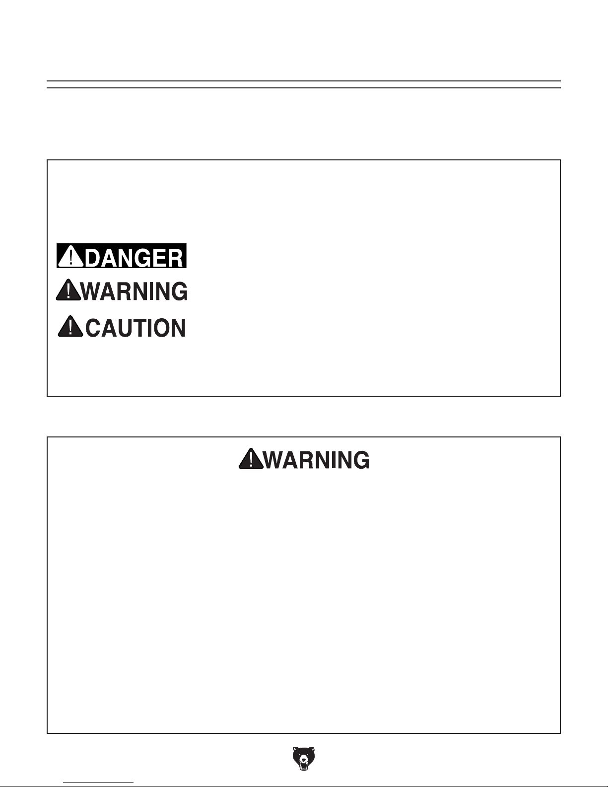
The purpose of safety symbols is to attract your attention to possible hazardous conditions.
This manual uses a series of symbols and signal words intended to convey the level of importance of the safety messages. The progression of symbols is described below. Remember that
safety messages by themselves do not eliminate danger and are not a substitute for proper
accident prevention measures. Always use common sense and good judgment.
Indicates an imminently hazardous situation which, if not avoided,
WILL result in death or serious injury.
Indicates a potentially hazardous situation which, if not avoided,
COULD result in death or serious injury.
Indicates a potentially hazardous situation which, if not avoided,
MAY result in minor or moderate injury. It may also be used to alert
against unsafe practices.
This symbol is used to alert the user to useful information about
NOTICE
proper operation of the machine.
Safety Instructions for Machinery
OWNER’S MANUAL. Read and understand this
owner’s manual BEFORE using machine.
TRAINED OPERATORS ONLY. Untrained operators have a higher risk of being hurt or killed.
Only allow trained/supervised people to use this
machine. When machine is not being used, disconnect power, remove switch keys, or lock-out
machine to prevent unauthorized use—especially
around children. Make your workshop kid proof!
DANGEROUS ENVIRONMENTS. Do not use
machinery in areas that are wet, cluttered, or have
poor lighting. Operating machinery in these areas
greatly increases the risk of accidents and injury.
MENTAL ALERTNESS REQUIRED. Full mental
alertness is required for safe operation of machinery. Never operate under the influence of drugs or
alcohol, when tired, or when distracted.
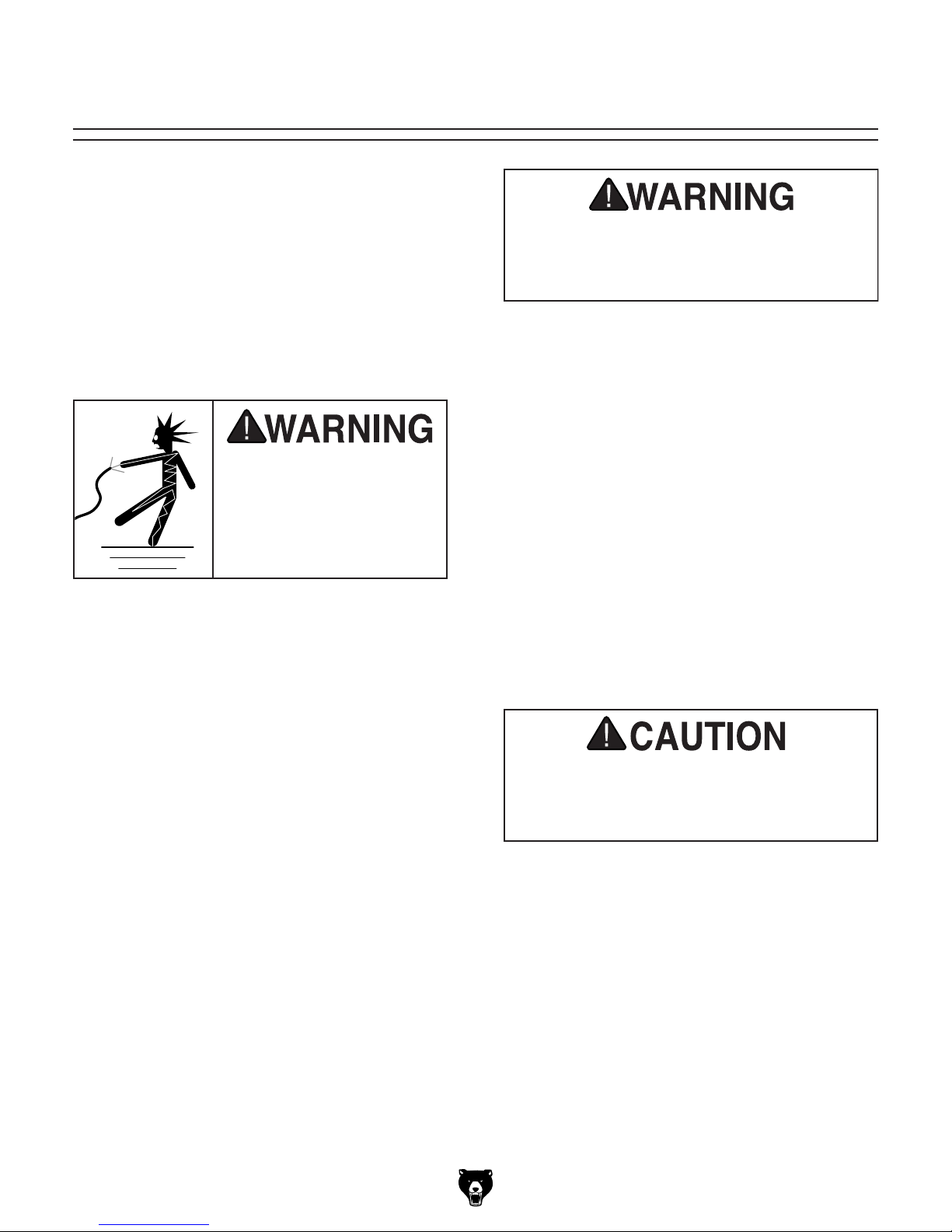
ELECTRICAL EQUIPMENT INJURY RISKS. You
can be shocked, burned, or killed by touching live
electrical components or improperly grounded
machinery. To reduce this risk, only allow qualified
service personnel to do electrical installation or
repair work, and always disconnect power before
accessing or exposing electrical equipment.
DISCONNECT POWER FIRST.
nect machine from power supply BEFORE making
adjustments, changing tooling, or servicing machine.
This prevents an injury risk from unintended startup
or contact with live electrical components.
EYE PROTECTION. Always wear ANSI-approved
safety glasses or a face shield when operating or
observing machinery to reduce the risk of eye
injury or blindness from flying particles. Everyday
eyeglasses are NOT approved safety glasses.
Always discon-
-8-
Model G0825 (Mfd. Since 02/17)

WEARING PROPER APPAREL. Do not wear
clothing, apparel or jewelry that can become
entangled in moving parts. Always tie back or
cover long hair. Wear non-slip footwear to reduce
risk of slipping and losing control or accidentally
contacting cutting tool or moving parts.
HAZARDOUS DUST. Dust created by machinery
operations may cause cancer, birth defects, or
long-term respiratory damage. Be aware of dust
hazards associated with each workpiece material. Always wear a NIOSH-approved respirator to
reduce your risk.
HEARING PROTECTION. Always wear hearing protection when operating or observing loud
machinery. Extended exposure to this noise
without hearing protection can cause permanent
hearing loss.
REMOVE ADJUSTING TOOLS. Tools left on
machinery can become dangerous projectiles
upon startup. Never leave chuck keys, wrenches,
or any other tools on machine. Always verify
removal before starting!
USE CORRECT TOOL FOR THE JOB. Only use
this tool for its intended purpose—do not force
it or an attachment to do a job for which it was
not designed. Never make unapproved modifications—modifying tool or using it differently than
intended may result in malfunction or mechanical
failure that can lead to personal injury or death!
AWKWARD POSITIONS. Keep proper footing
and balance at all times when operating machine.
Do not overreach! Avoid awkward hand positions
that make workpiece control difficult or increase
the risk of accidental injury.
CHILDREN & BYSTANDERS. Keep children and
bystanders at a safe distance from the work area.
Stop using machine if they become a distraction.
GUARDS & COVERS. Guards and covers reduce
accidental contact with moving parts or flying
debris. Make sure they are properly installed,
undamaged, and working correctly BEFORE
operating machine.
FORCING MACHINERY. Do not force machine.
It will do the job safer and better at the rate for
which it was designed.
NEVER STAND ON MACHINE. Serious injury
may occur if machine is tipped or if the cutting
tool is unintentionally contacted.
STABLE MACHINE. Unexpected movement during operation greatly increases risk of injury or
loss of control. Before starting, verify machine is
stable and mobile base (if used) is locked.
USE RECOMMENDED ACCESSORIES. Consult
this owner’s manual or the manufacturer for recommended accessories. Using improper accessories will increase the risk of serious injury.
UNATTENDED OPERATION. To reduce the
risk of accidental injury, turn machine OFF and
ensure all moving parts completely stop before
walking away. Never leave machine running
while unattended.
MAINTAIN WITH CARE. Follow all maintenance
instructions and lubrication schedules to keep
machine in good working condition. A machine
that is improperly maintained could malfunction,
leading to serious personal injury or death.
DAMAGED PARTS. Regularly inspect machine
for damaged, loose, or mis-adjusted parts—or
any condition that could affect safe operation.
Immediately repair/replace BEFORE operating
machine. For your own safety, DO NOT operate
machine with damaged parts!
MAINTAIN POWER CORDS. When disconnecting cord-connected machines from power, grab
and pull the plug—NOT the cord. Pulling the cord
may damage the wires inside. Do not handle
cord/plug with wet hands. Avoid cord damage by
keeping it away from heated surfaces, high traffic
areas, harsh chemicals, and wet/damp locations.
EXPERIENCING DIFFICULTIES. If at any time
you experience difficulties performing the intended operation, stop using the machine! Contact our
Technical Support at (570) 546-9663.
Model G0825 (Mfd. Since 02/17)
-9-
Additional Safety for Edgebanders
Serious injury can occur from getting fingers pinched or crushed between workpiece and feed
rollers, or getting hair/clothing entangled in feed rollers. Touching hot parts can cause serious
burns. Long-term respiratory damage can occur from using edgebander without a respirator
and adequate ventilation. To minimize risk of injury, anyone operating this machine MUST
completely heed hazards and warnings below.
HAND PLACEMENT. The gap between the feed
roller and glue spindle presents a risk of pinching
or crushing injuries. Minimize this risk by keeping
fingers clear of infeed area when feeding edgebanding.
AVOIDING ENTANGLEMENT. Becoming entangled in feed rollers can cause crushing injuries. To
avoid these hazards, DO NOT wear loose clothing, gloves, or jewelry, and tie back long hair.
GLUE POT & GLUE APPLICATOR. The glue pot
and glue applicator get very hot and can cause
serious burns. Always wear gloves when adding
glue to glue pot. When servicing glue pot and
applicator, make sure machine is turned OFF,
disconnected from power, and components have
properly cooled before handling.
SAFETY DEVICES. Do not modify or disable any
guards or other safety devices on this machine.
Doing so will void the warranty and expose operator to serious injury from mechanical and electrical components inside machine.
WEAR PROPER PPE. Always wear safety glasses and respirator when operating edgebander.
Always wear gloves when adding glue to glue pot.
DISCONNECT POWER. To reduce risk of electrocution or injury from unexpected startup, make
sure machine is turned OFF, disconnected from
power, all moving parts have come to a complete
stop, and glue pot has cooled before starting any
inspection, adjustment, or maintenance procedure.
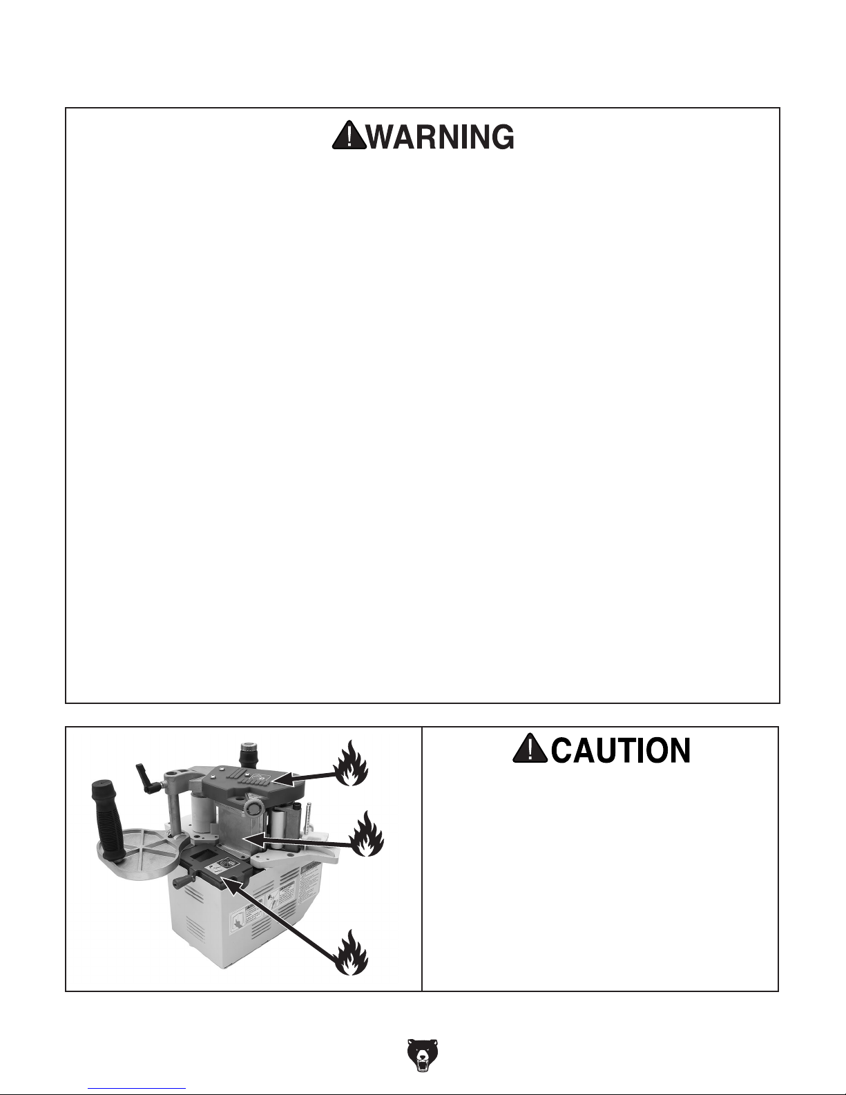
HEATED FENCE. Heated fence is very hot and
can cause serious burns. Avoid touching fence,
especially when feeding small workpieces.
ADEQUATE VENTILATION. When melted,
edgebanding glue pellets can produce vapors
and fumes that may irritate the nose, throat, and
respiratory tract and cause a risk of long-term
respiratory damage. Only operate this machine
with proper ventilation near work area. Always
wear a properly fitting respirator with filters rated
for organic vapor.
-10 -
Pay close attention to heated surfaces to
avoid accidental contact while operating
machine and when preparing machine for
storage. Store machine only when heated
elements are properly cooled.
Model G0825 (Mfd. Since 02/17)
SECTION 2: POWER SUPPLY
Before installing the machine, consider the availability and proximity of the required power supply
circuit. If an existing circuit does not meet the
requirements for this machine, a new circuit must
be installed. To minimize the risk of electrocution,
fire, or equipment damage, installation work and
electrical wiring must be done by an electrician or
qualified service personnel in accordance with all
applicable codes and standards.
or equipment damage
may occur if machine is
not properly grounded
and connected to power
The full-load current rating is the amperage a
machine draws at 100% of the rated output power.
On machines with multiple motors, this is the
amperage drawn by the largest motor or sum of all
motors and electrical devices that might operate
at one time during normal operations.
The full-load current is not the maximum amount
of amps that the machine will draw. If the machine
is overloaded, it will draw additional amps beyond
the full-load rating.
If the machine is overloaded for a sufficient length
of time, damage, overheating, or fire may result—
especially if connected to an undersized circuit.
To reduce the risk of these hazards, avoid overloading the machine during operation and make
sure it is connected to a power supply circuit that
meets the specified circuit requirements.
For your own safety and protection of
Note: Circuit requirements in this manual apply to
a dedicated circuit—where only one machine will
be running on the circuit at a time. If machine will
be connected to a shared circuit where multiple
machines may be running at the same time, consult an electrician or qualified service personnel to
ensure circuit is properly sized for safe operation.
A power supply circuit includes all electrical
equipment between the breaker box or fuse panel
in the building and the machine. The power supply circuit used for this machine must be sized to
safely handle the full-load current drawn from the
machine for an extended period of time. (If this
machine is connected to a circuit protected by
fuses, use a time delay fuse marked D.)
This machine is prewired to operate on a power
supply circuit that has a verified ground and meets
the following requirements:
process. DO NOT connect to power until
Availability
Electrocution, fire, shock,
Serious injury could occur if you connect
machine to power before completing setup
instructed later in this manual.
110V Circuit Requirements
Nominal Voltage .................... 110V, 115V, 120V
Cycle .......................................................... 60 Hz
Phase ........................................... Single-Phase
Power Supply Circuit ......................... 15 Amps
supply.
Full-Load Current Rating
Full-Load Current Rating at 110V ........ 8 Amps
Model G0825 (Mfd. Since 02/17)
property, consult an electrician if you are
unsure about wiring practices or electrical
codes in your area.
-11-
Improper connection of the equipment-grounding
wire can result in a risk of electric shock. The
wire with green insulation (with or without yellow
stripes) is the equipment-grounding wire. If repair
or replacement of the power cord or plug is necessary, do not connect the equipment-grounding
wire to a live (current carrying) terminal.
Check with a qualified electrician or service personnel if you do not understand these grounding
requirements, or if you are in doubt about whether
the tool is properly grounded. If you ever notice
that a cord or plug is damaged or worn, disconnect it from power, and immediately replace it with
a new one.
We do not recommend using an extension cord
with this machine.
cord, only use it if absolutely necessary and only
on a temporary basis.
Extension cords cause voltage drop, which can
damage electrical components and shorten motor
life. Voltage drop increases as the extension cord
size gets longer and the gauge size gets smaller
(higher gauge numbers indicate smaller sizes).
Any extension cord used with this machine must
be in good condition and contain a ground wire
and matching plug/receptacle. Additionally, it must
meet the following size requirements:
Grounding & Plug Requirements
it will not fit the outlet, have a qualified
electrician install the proper outlet with a
This machine MUST be grounded. In the event
of certain malfunctions or breakdowns, grounding
reduces the risk of electric shock by providing a
path of least resistance for electric current.
This machine is equipped with a power cord that
has an equipment-grounding wire and a grounding
plug. Only insert plug into a matching receptacle
(outlet) that is properly installed and grounded in
accordance with all local codes and ordinances.
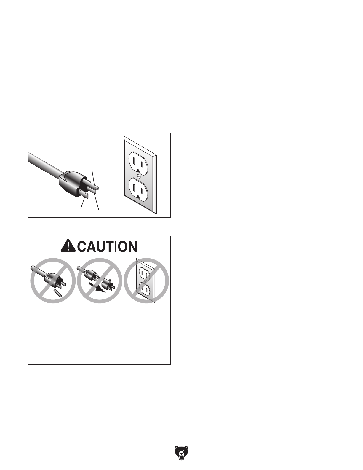
DO NOT modify the provided plug!
GROUNDED
5-15 RECEPTACLE
Grounding Prong
5-15 PLUG
Extension Cords
If you must use an extension
Neutral Hot
Figure 5. Typical 5-15 plug and receptacle.
SHOCK HAZARD!
Two-prong outlets do not meet the grounding
requirements for this machine. Do not modify
or use an adapter on the plug provided—if
verified ground.
-12-
Minimum Gauge Size ...........................14 AWG
Maximum Length (Shorter is Better).......50 ft.
Model G0825 (Mfd. Since 02/17)
 Loading...