

Grizzly G0818 Owner's Manual
MODEL G0818
METAL DUST COLLECTOR
OWNER'S MANUAL
(For models manufactured since 10/16)
COPYRIGHT © MARCH, 2017 BY GRIZZLY INDUSTRIAL, INC.
WARNING: NO PORTION OF THIS MANUAL MAY BE REPRODUCED IN ANY SHAPE
OR FORM WITHOUT THE WRITTEN APPROVAL OF GRIZZLY INDUSTRIAL, INC.
#KB18550 PRINTED IN CHINA
V1. 0 3 .17

This manual provides critical safety instructions on the proper setup,
operation, maintenance, and service of this machine/tool. Save this
document, refer to it often, and use it to instruct other operators.
Failure to read, understand and follow the instructions in this manual
may result in fire or serious personal injury—including amputation,
electrocution, or death.
The owner of this machine/tool is solely responsible for its safe use.
This responsibility includes but is not limited to proper installation in
a safe environment, personnel training and usage authorization,
proper inspection and maintenance, manual availability and comprehension, application of safety devices, cutting/sanding/grinding tool
integrity, and the usage of personal protective equipment.
The manufacturer will not be held liable for injury or property damage
from negligence, improper training, machine modifications or misuse.
Some dust created by power sanding, sawing, grinding, drilling, and
other construction activities contains chemicals known to the State
of California to cause cancer, birth defects or other reproductive
harm. Some examples of these chemicals are:
• Lead from lead-based paints.
• Crystalline silica from bricks, cement and other masonry products.
• Arsenic and chromium from chemically-treated lumber.
Your risk from these exposures varies, depending on how often you
do this type of work. To reduce your exposure to these chemicals:
Work in a well ventilated area, and work with approved safety equipment, such as those dust masks that are specially designed to filter
out microscopic particles.

Table of Contents
INTRODUCTION ............................................................................................................................... 2
Contact Info ................................................................................................................................ 2
Manual Accuracy ........................................................................................................................ 2
Identification ............................................................................................................................... 3
Machine Data Sheet ................................................................................................................... 4
SECTION 1: SAFETY ....................................................................................................................... 6
Safety Instructions for Machinery ............................................................................................... 6
Additional Safety for Metal Dust Collectors ................................................................................ 8
SECTION 2: POWER SUPPLY ........................................................................................................ 9
SECTION 3: SETUP ....................................................................................................................... 11
Needed for Setup ..................................................................................................................... 11
Unpacking ................................................................................................................................ 11
Inventory ................................................................................................................................... 12
Hardware Recognition Chart .................................................................................................... 13
Site Considerations .................................................................................................................. 14
Lifting & Placing ....................................................................................................................... 15
Assembly .................................................................................................................................. 15
Collection Ducting .................................................................................................................... 17
System Grounding.................................................................................................................... 18
Test Run ................................................................................................................................... 19
SECTION 4: OPERATIONS ........................................................................................................... 20
Operation .................................................................................................................................. 20
SECTION 5: ACCESSORIES ......................................................................................................... 21
SECTION 6: MAINTENANCE......................................................................................................... 25
Schedule .................................................................................................................................. 25
Cleaning Exterior ...................................................................................................................... 25
Cleaning Collection Drawer & Dust Tray ................................................................................. 25
Cleaning Impeller ..................................................................................................................... 26
Cleaning Ducts ......................................................................................................................... 26
Cleaning/Replacing Filters ....................................................................................................... 27
SECTION 7: SERVICE ................................................................................................................... 28
Troubleshooting ........................................................................................................................ 28
SECTION 8: WIRING ...................................................................................................................... 30
Wiring Safety Instructions ........................................................................................................ 30
Wiring Diagram......................................................................................................................... 31
SECTION 9: PARTS ....................................................................................................................... 32
Breakdown ............................................................................................................................... 32
Parts List .................................................................................................................................. 33
Labels & Cosmetics ................................................................................................................. 34
WARRANTY & RETURNS ............................................................................................................. 37
We stand behind our machines! If you have questions or need help, contact us with the information
below. Before contacting, make sure you get the
serial number
machine ID label. This will help us help you faster.
We want your feedback on this manual. What did
you like about it? Where could it be improved?
Please take a few minutes to give us feedback.
Email: manuals@grizzly.com
We are proud to provide a high-quality owner’s
manual with your new machine!
We
instructions, specifications, drawings, and photographs
in this manual. Sometimes we make mistakes, but
our policy of continuous improvement also means
that
you receive is
slightly different than shown in the manual
If you find this to be the case, and the difference
between the manual and machine leaves you
confused or unsure about something
check our
website for an updated version. W
current
manuals and
on our web-
site at
Alternatively, you can call our Technical Support
for help. Before calling, make sure you write down
the
from
the machine ID label (see below). This information
is required for us to provide proper tech support,
and it helps us determine if updated documentation is available for your machine.
INTRODUCTION
Contact Info
and manufacture date from the
Grizzly Technical Support
1815 W. Battlefield
Springfield, MO 65807
Phone: (570) 546-9663
Email: techsupport@grizzly.com
Grizzly Documentation Manager
P.O. Box 2069
Bellingham, WA 98227-2069
Manual Accuracy
made every effort to be exact with the
sometimes the machine
.
,
e post
manual updates for free
www.grizzly.com.
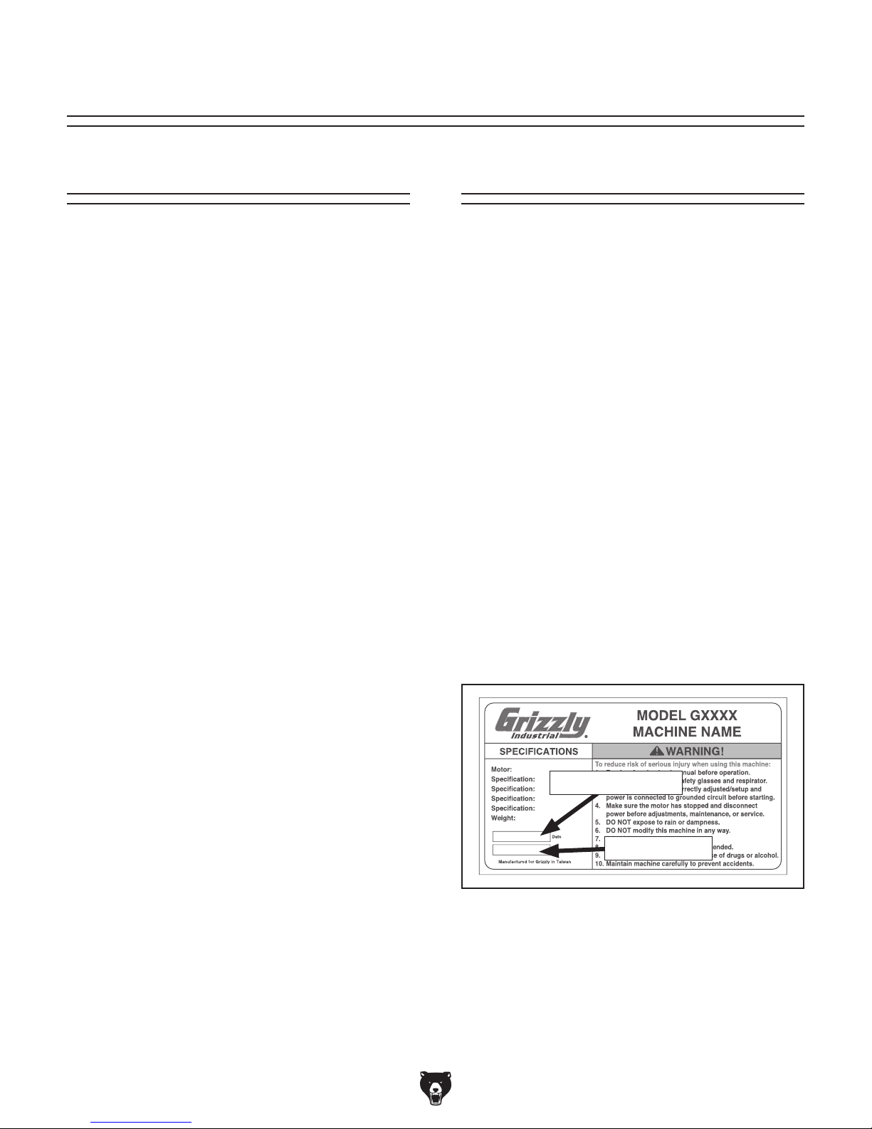
Manufacture Date and Serial Number
Manufacture Date
Serial Number
-2-
Model G0818 (Mfd. Since 10/16)
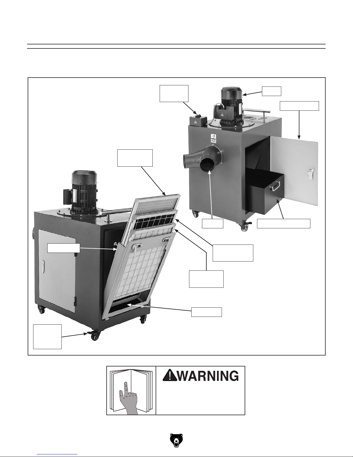
Identification
To reduce your risk of
serious injury, read this
entire manual BEFORE
Become familiar with the names and locations of the controls and features shown below to better understand
the instructions in this manual.
Filter Door
Stainless
Mesh Filter
ON/OFF
Switch
Y-Inlet
Active
Carbon Filter
Motor
Access Door
Collection Drawer
Locking
Casters
(1 of 2)
Model G0818 (Mfd. Since 10/16)
Pleated
Micro Filter
Dust Tray
using machine.
-3-

Customer Service #: (570) 546-9663 · To Order Call: (800) 523-4777 · Fax #: (800) 438-5901
MODEL G0818 METAL DUST COLLECTOR
Product Dimensions:
Weight ........................................................................................................................................................................... 256 lbs.
Width (side-to-side) x Depth (front-to-back) x Height .................................................................................39 x 20 x 41-1/2 in.
Footprint (Width x Depth) .....................................................................................................................................27-1/2 x 20 in.
Shipping Dimensions:
Type .................................................................................................................................................................... Wooden Crate
Content .......................................................................................................................................................................... Machine
Weight ............................................................................................................................................................................ 309 lbs.
Length x Width x Height .....................................................................................................................................30 x 22 x 46 in.
Must Ship Upright .................................................................................................................................................................Yes
Electrical:
Power Requirement ........................................................................................................................ 220V, Single-Phase, 60 Hz
Full-Load Current Rating ..................................................................................................................................................... 8.2A
Minimum Circuit Size ........................................................................................................................................................... 15A
Connection Type ..................................................................................................................................................... Cord & Plug
Power Cord Included ............................................................................................................................................................Yes
Power Cord Length ...............................................................................................................................................................6 ft.
Power Cord Gauge ....................................................................................................................................................... 16 AWG
Plug Included .......................................................................................................................................................................6-15
Switch Type ............................................................................................................. Toggle Switch w/Removable Locking Key
Motor:
Main
Type ................................................................................................................................ TEFC Capacitor-Start Induction
Horsepower ............................................................................................................................................................1.5 HP
Voltage ..................................................................................................................................................................... 220V
Phase .................................................................................................................................................................. 1-Phase
Amps ......................................................................................................................................................................... 8.2A
Speed ...............................................................................................................................................................3450 RPM
Cycle ........................................................................................................................................................................ 60 Hz
Power Transfer ............................................................................................................................................... Direct Drive
Bearings ............................................................................................................... Shielded and Permanently Lubricated
-4-
Model G0818 (Mfd. Since 10/16)

Main Specifications:
Operation Information
Dust Collector Type .................................................................................................................................................. Metal
Airflow Performance ........................................................................................................................................... 755 CFM
Max. Static Pressure (at 0 CFM) ..........................................................................................................................8-5/8 in.
Main Inlet Size ............................................................................................................................................................ 6 in.
Inlet Adapter Included .................................................................................................................................................Yes
Inlet Adapter Type .................................................................................................................................................. Y-Inlet
Number of Adapter Inlets ................................................................................................................................................2
Adapter Inlet Size .......................................................................................................................................................4 in.
Max. Material Collection Capacity ................................. 1 cu. ft. (Main Compartment), 0.23 cu. ft. (Filter Compartment)
Filter Information
Number of Filters ............................................................................................................................. 3, Aluminum-Framed
Total Filter Surface Area ..................................................................................................................................6.48 sq. ft.
First-Stage Filter Type ............................................................................................................................... Stainless Filter
First-Stage Filter Rating ..................................................................................................................................30 Microns
First-Stage Filter Size (Length x Width x Thickness) ............................................................. 15-3/4 x 19-3/4 x 13/16 in.
Second-Stage Filter Type ..................................................................................................................Active Carbon Filter
Second-Stage Filter Rating ............................................................................................................................... 5 Microns
Second-Stage Filter Size (Length x Width x Thickness) ........................................................ 15-3/4 x 19-3/4 x 13/16 in.
Third-Stage Filter Type ............................................................................................................ Pleated Outer Micro-Filter
Third-Stage Filter Rating .....................................................................................................................................1 Micron
Third-Stage Filter Size (Length x Width x Thickness) ............................................................ 15-3/4 x 19-3/4 x 13/16 in.
Impeller Information
Impeller Type ........................................................................................................... Precision, Spin-Balanced Aluminum
Impeller Size .......................................................................................................................................................12-3/4 in.
Impeller Blade Thickness ......................................................................................................................................5/16 in.
Construction
Base ..........................................................................................................................................................................Steel
Frame ........................................................................................................................................................................Steel
Side Walls .................................................................................................................................................................Steel
Collection Drawers ....................................................................................................................................................Steel
Caster .................................................................................................................................................................... Rubber
Impeller ..................................................................................................................................................... Aluminum Alloy
Blower Housing ........................................................................................................................................ Cast Aluminum
Other Specifications:
Country of Origin ............................................................................................................................................................... China
Warranty ........................................................................................................................................................................... 1 Year
Approximate Assembly & Setup Time ...................................................................................................................... 30 Minutes
Sound Rating .................................................................................................................................................................... 85 dB
Serial Number Location ..................................................................................................................................Machine ID Label
ISO 9001 Factory ..................................................................................................................................................................Yes
Certified by a Nationally Recognized Testing Laboratory (NRTL) ......................................................................................... No
Model G0818 (Mfd. Since 10/16)
-5-
SECTION 1: SAFETY
For Your Own Safety, Read Instruction
Manual Before Operating This Machine
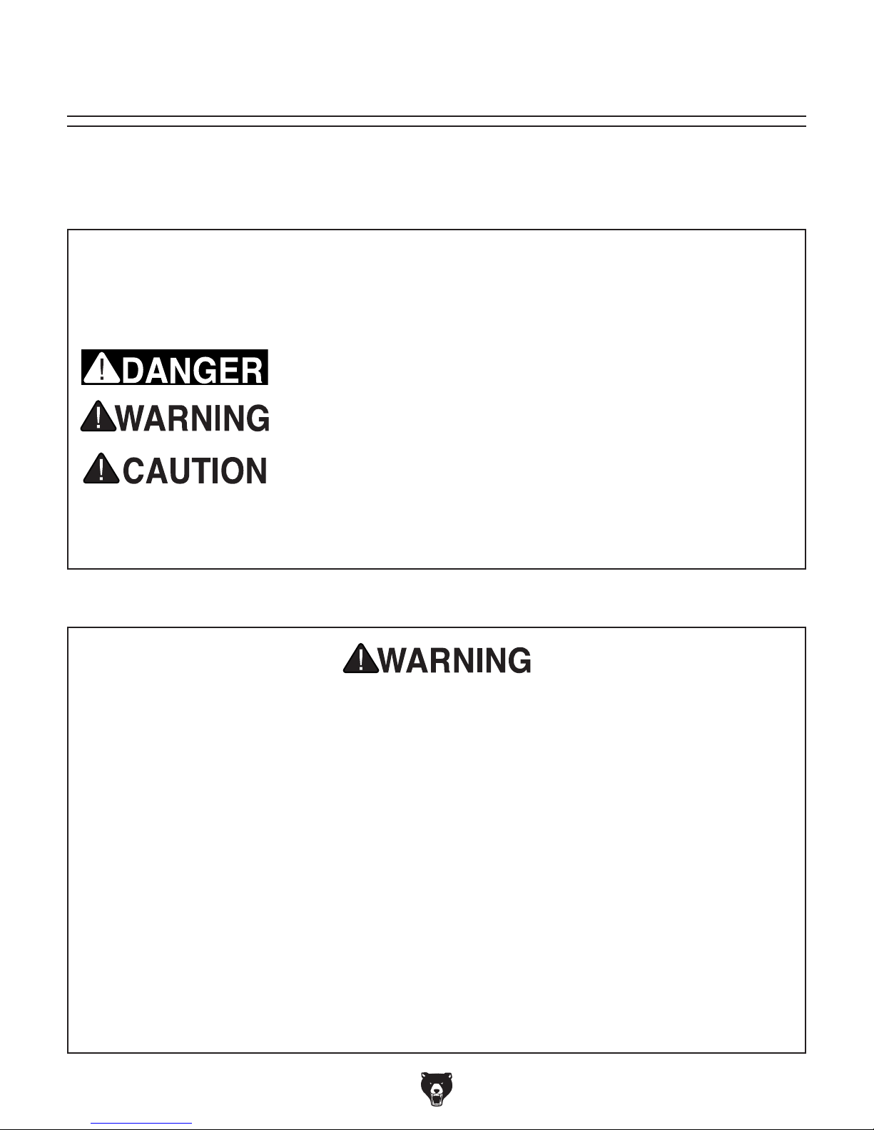
The purpose of safety symbols is to attract your attention to possible hazardous conditions.
This manual uses a series of symbols and signal words intended to convey the level of importance of the safety messages. The progression of symbols is described below. Remember that
safety messages by themselves do not eliminate danger and are not a substitute for proper
accident prevention measures. Always use common sense and good judgment.
Indicates an imminently hazardous situation which, if not avoided,
WILL result in death or serious injury.
Indicates a potentially hazardous situation which, if not avoided,
COULD result in death or serious injury.
Indicates a potentially hazardous situation which, if not avoided,
MAY result in minor or moderate injury. It may also be used to alert
against unsafe practices.
This symbol is used to alert the user to useful information about
NOTICE
proper operation of the machine.
Safety Instructions for Machinery
OWNER’S MANUAL. Read and understand this
owner’s manual BEFORE using machine.
TRAINED OPERATORS ONLY. Untrained operators have a higher risk of being hurt or killed.
Only allow trained/supervised people to use this
machine. When machine is not being used, disconnect power, remove switch keys, or lock-out
machine to prevent unauthorized use—especially
around children. Make workshop kid proof!
DANGEROUS ENVIRONMENTS. Do not use
machinery in areas that are wet, cluttered, or have
poor lighting. Operating machinery in these areas
greatly increases the risk of accidents and injury.
MENTAL ALERTNESS REQUIRED. Full mental
alertness is required for safe operation of machinery. Never operate under the influence of drugs or
alcohol, when tired, or when distracted.
ELECTRICAL EQUIPMENT INJURY RISKS. You
can be shocked, burned, or killed by touching live
electrical components or improperly grounded
machinery. To reduce this risk, only allow qualified
service personnel to do electrical installation or
repair work, and always disconnect power before
accessing or exposing electrical equipment.
DISCONNECT POWER FIRST.
nect machine from power supply BEFORE making
adjustments, changing tooling, or servicing machine.
This prevents an injury risk from unintended startup
or contact with live electrical components.
EYE PROTECTION. Always wear ANSI-approved
safety glasses or a face shield when operating or
observing machinery to reduce the risk of eye
injury or blindness from flying particles. Everyday
eyeglasses are NOT approved safety glasses.
Always discon-
-6-
Model G0818 (Mfd. Since 10/16)

WEARING PROPER APPAREL. Do not wear
clothing, apparel or jewelry that can become
entangled in moving parts. Always tie back or
cover long hair. Wear non-slip footwear to reduce
risk of slipping and losing control or accidentally
contacting cutting tool or moving parts.
HAZARDOUS DUST. Dust created by machinery
operations may cause cancer, birth defects, or
long-term respiratory damage. Be aware of dust
hazards associated with each workpiece material. Always wear a NIOSH-approved respirator to
reduce your risk.
HEARING PROTECTION. Always wear hearing protection when operating or observing loud
machinery. Extended exposure to this noise
without hearing protection can cause permanent
hearing loss.
REMOVE ADJUSTING TOOLS. Tools left on
machinery can become dangerous projectiles
upon startup. Never leave chuck keys, wrenches,
or any other tools on machine. Always verify
removal before starting!
USE CORRECT TOOL FOR THE JOB. Only use
this tool for its intended purpose—do not force
it or an attachment to do a job for which it was
not designed. Never make unapproved modifications—modifying tool or using it differently than
intended may result in malfunction or mechanical
failure that can lead to personal injury or death!
AWKWARD POSITIONS. Keep proper footing
and balance at all times when operating machine.
Do not overreach! Avoid awkward hand positions
that make workpiece control difficult or increase
the risk of accidental injury.
CHILDREN & BYSTANDERS. Keep children and
bystanders at a safe distance from the work area.
Stop using machine if they become a distraction.
GUARDS & COVERS. Guards and covers reduce
accidental contact with moving parts or flying
debris. Make sure they are properly installed,
undamaged, and working correctly BEFORE
operating machine.
FORCING MACHINERY. Do not force machine.
It will do the job safer and better at the rate for
which it was designed.
NEVER STAND ON MACHINE. Serious injury
may occur if machine is tipped or if the cutting
tool is unintentionally contacted.
STABLE MACHINE. Unexpected movement during operation greatly increases risk of injury or
loss of control. Before starting, verify machine is
stable and mobile base (if used) is locked.
USE RECOMMENDED ACCESSORIES. Consult
this owner’s manual or the manufacturer for recommended accessories. Using improper accessories will increase the risk of serious injury.
UNATTENDED OPERATION. To reduce the
risk of accidental injury, turn machine OFF and
ensure all moving parts completely stop before
walking away. Never leave machine running
while unattended.
MAINTAIN WITH CARE. Follow all maintenance
instructions and lubrication schedules to keep
machine in good working condition. A machine
that is improperly maintained could malfunction,
leading to serious personal injury or death.
DAMAGED PARTS. Regularly inspect machine
for damaged, loose, or mis-adjusted parts—or
any condition that could affect safe operation.
Immediately repair/replace BEFORE operating
machine. For your own safety, DO NOT operate
machine with damaged parts!
MAINTAIN POWER CORDS. When disconnecting cord-connected machines from power, grab
and pull the plug—NOT the cord. Pulling the cord
may damage the wires inside. Do not handle
cord/plug with wet hands. Avoid cord damage by
keeping it away from heated surfaces, high traffic
areas, harsh chemicals, and wet/damp locations.
EXPERIENCING DIFFICULTIES. If at any time
you experience difficulties performing the intended operation, stop using the machine! Contact our
Technical Support at (570) 546-9663.
Model G0818 (Mfd. Since 10/16)
-7-

Additional Safety for Metal Dust Collectors
Long-term respiratory damage, metal toxicity, cancer, or birth defects can occur from improperly
using, setting up, or servicing machine, and using this machine without wearing a respirator.
Explosions or fire can result if machine is used to capture incorrect materials or if dust/waste
material is exposed to an ignition source. To reduce these risks, operator and bystanders MUST
completely heed the warnings below.
USE FOR INTENDED PURPOSE. This metal
dust collector is only designed to capture noncombustible or non-explosible metal particles.
Collect only one type of metal/material at one
time. DO NOT use to capture materials made
from wood or wood products. DO NOT use it to
collect lead, magnesium, niobium, tantalum, titanium, zirconium, hafnium, asbestos, crystalline
silica, gypsum, or any other non-metal products.
DO NOT use to capture welding fumes, gasses,
vapors, liquids, smoke, or ordinary combustible
materials. DO NOT connect this dust collector to
any machine using a coolant system.
WEAR PROPER PPE. Dust created from cutting,
grinding, sanding, etc. may cause cancer, birth
defects, or long-term respiratory damage. Be
aware of the dust hazards, exposure limits, and
toxicity associated with each type of workpiece
material being collected. Very fine dust/particles
may not be captured by filters and may become
airborne in the work area. Anyone working in this
same work area MUST wear a NIOSH-approved
respirator and eye protection rated for the workpiece material.
TOXIC METALS. Exposure (or over-exposure) to
certain types of metal dusts or fumes can result
in serious, potentially deadly health effects. To
reduce this risk, research toxicity of metal types
you work with and always seek to minimize/eliminate exposure to yourself and others.
CLEANING DRAWERS. Wear safety goggles
and a NIOSH-approved respirator (rated for the
metal type) when emptying and cleaning collection drawer and dust tray. Empty only into an
approved, closed-top metal container, taking care
to minimize amount of dust allowed to become
airborne. Prevent spread of dust onto hands or
clothing. Dispose of waste properly and according
to local regulations for material type.
HIGH-HAZARD MATERIAL. This machine does
NOT protect against highly hazardous materials,
such as lead dust, asbestos fibers, or radioactive
particles. These materials MUST be collected
with special filtration equipment because of their
high health/contamination hazard and difficulty of
filtration. DO NOT attempt to collect such materials with this machine.
RISK OF FIRE/EXPLOSIONS. To minimize static
electrical charge, only connect with smoothwalled, sheet-metal ducting—do not use PVC.
Entire collection system (collector + ductwork)
must be bonded and grounded. Fine metal dust
particles can ignite, depending on material type
and circumstances. Know about and be prepared
to safely fight a combustible metal fire by conducting a combustible screening test under Chapter
4 of NFPA 484. Keep machine away from pilot
lights, open flames, or other ignition sources.
NEVER use near chemical fumes or within an
enclosed spray booth.
-8-
SAFE OPERATING LOCATION. DO NOT place
metal dust collector where it can be exposed to
rain or moisture. Exposure to water creates a
shock hazard and will reduce life of machine.
PROPERLY MAINTAIN MACHINE. Ke e p machine
in proper working condition to help ensure all
guards and components function as intended.
Perform routine inspections and all necessary
maintenance indicated in owner’s manual. Never
operate machine with damaged or worn parts.
Duct must be disconnected before service. Never
operate machine with filters or covers removed.
Model G0818 (Mfd. Since 10/16)
SECTION 2: POWER SUPPLY
Before installing the machine, consider the availability and proximity of the required power supply
circuit. If an existing circuit does not meet the
requirements for this machine, a new circuit must
be installed. To minimize the risk of electrocution,
fire, or equipment damage, installation work and
electrical wiring must be done by an electrician or
qualified service personnel in accordance with all
applicable codes and standards.
or equipment damage
may occur if machine is
not properly grounded
and connected to power
The full-load current rating is the amperage a
machine draws at 100% of the rated output power.
On machines with multiple motors, this is the
amperage drawn by the largest motor or sum of all
motors and electrical devices that might operate
at one time during normal operations.
The full-load current is not the maximum amount
of amps that the machine will draw. If the machine
is overloaded, it will draw additional amps beyond
the full-load rating.
If the machine is overloaded for a sufficient length
of time, damage, overheating, or fire may result—
especially if connected to an undersized circuit.
To reduce the risk of these hazards, avoid overloading the machine during operation and make
sure it is connected to a power supply circuit that
meets the specified circuit requirements.
Serious injury could occur if you connect
process. DO NOT connect to power until
For your own safety and protection of
Note: Circuit requirements in this manual apply to
a dedicated circuit—where only one machine will
be running on the circuit at a time. If machine will
be connected to a shared circuit where multiple
machines may be running at the same time, consult an electrician or qualified service personnel to
ensure circuit is properly sized for safe operation.
A power supply circuit includes all electrical
equipment between the breaker box or fuse panel
in the building and the machine. The power supply circuit used for this machine must be sized to
safely handle the full-load current drawn from the
machine for an extended period of time. (If this
machine is connected to a circuit protected by
fuses, use a time delay fuse marked D.)
This machine is prewired to operate on a power
supply circuit that has a verified ground and meets
the following requirements:
Availability
machine to power before completing setup
instructed later in this manual.
Circuit Information
Electrocution, fire, shock,
supply.
Full-Load Current Rating
Full-Load Current Rating at 220V .... 8.2 Amps
Model G0818 (Mfd. Since 10/16)
property, consult an electrician if you are
unsure about wiring practices or electrical
codes in your area.
Circuit Requirements for 220V
Nominal Voltage .........20 8V, 22 0V, 2 30V, 24 0V
Cycle .......................................................... 60 Hz
Phase ........................................... Single-Phase
Power Supply Circuit ......................... 15 Amps
Plug/Receptacle ............................. NEMA 6-15
-9-
Improper connection of the equipment-grounding
wire can result in a risk of electric shock. The
wire with green insulation (with or without yellow
stripes) is the equipment-grounding wire. If repair
or replacement of the power cord or plug is necessary, do not connect the equipment-grounding
wire to a live (current carrying) terminal.
We do not recommend using an extension cord
with this machine.
cord, only use it if absolutely necessary and only
on a temporary basis.
Extension cords cause voltage drop, which can
damage electrical components and shorten motor
life. Voltage drop increases as the extension cord
size gets longer and the gauge size gets smaller
(higher gauge numbers indicate smaller sizes).
Any extension cord used with this machine must
be in good condition and contain a ground wire
and matching plug/receptacle. Additionally, it must
meet the following size requirements:
Grounding Requirements
This machine MUST be grounded. In the event
of certain malfunctions or breakdowns, grounding
reduces the risk of electric shock by providing a
path of least resistance for electric current.
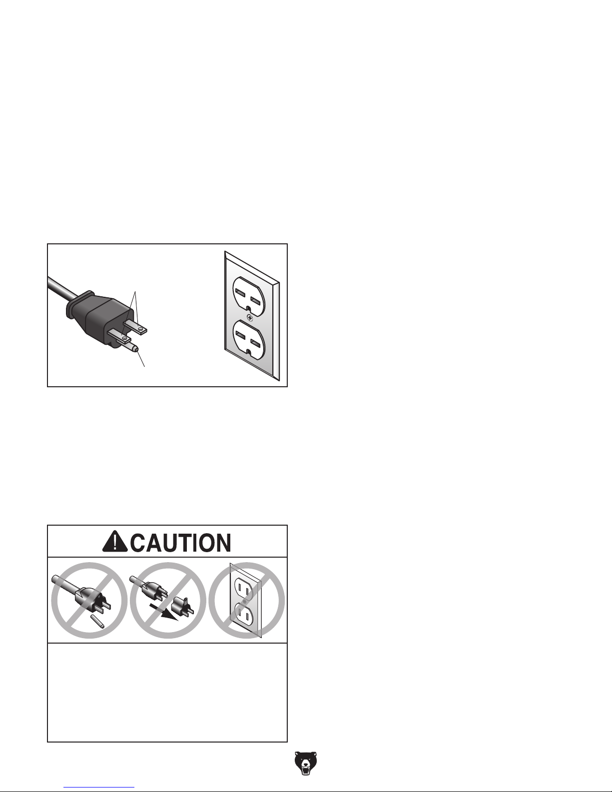
For 220V operation: This machine is equipped
with a power cord that has an equipment-grounding wire and a grounding plug (see following figure). The plug must only be inserted into a matching receptacle (outlet) that is properly installed
and grounded in accordance with all local codes
and ordinances.
it will not fit the outlet, have a qualified
electrician install the proper outlet with a
Check with a qualified electrician or service personnel if you do not understand these grounding
requirements, or if you are in doubt about whether
the tool is properly grounded. If you ever notice
that a cord or plug is damaged or worn, disconnect it from power, and immediately replace it with
a new one.
GROUNDED
6-15 RECEPTACLE
Current Carrying Prongs
6-15 PLUG
Extension Cords
If you must use an extension
Grounding Prong
Figure 1. Typical 6-15 plug and receptacle.
SHOCK HAZARD!
Two-prong outlets do not meet the grounding
requirements for this machine. Do not modify
or use an adapter on the plug provided—if
verified ground.
-10 -
Minimum Gauge Size ...........................14 AWG
Maximum Length (Shorter is Better).......50 ft.
Model G0818 (Mfd. Since 10/16)
 Loading...