

Grizzly G0817 Owner's Manual

MODEL G0817
14" RESAW BANDSAW
w/FOOT BRAKE
OWNER'S MANUAL
(For models manufactured since 05/16)
COPYRIGHT © OCTOBER, 2016 BY GRIZZLY INDUSTRIAL, INC.
WARNING: NO PORTION OF THIS MANUAL MAY BE REPRODUCED IN ANY SHAPE
OR FORM WITHOUT THE WRITTEN APPROVAL OF GRIZZLY INDUSTRIAL, INC.
#WK18234 PRINTED IN TAIWAN
V1.1 0.16

This manual provides critical safety instructions on the proper setup,
operation, maintenance, and service of this machine/tool. Save this
document, refer to it often, and use it to instruct other operators.
Failure to read, understand and follow the instructions in this manual
may result in fire or serious personal injury—including amputation,
electrocution, or death.
The owner of this machine/tool is solely responsible for its safe use.
This responsibility includes but is not limited to proper installation in
a safe environment, personnel training and usage authorization,
proper inspection and maintenance, manual availability and comprehension, application of safety devices, cutting/sanding/grinding tool
integrity, and the usage of personal protective equipment.
The manufacturer will not be held liable for injury or property damage
from negligence, improper training, machine modifications or misuse.
Some dust created by power sanding, sawing, grinding, drilling, and
other construction activities contains chemicals known to the State
of California to cause cancer, birth defects or other reproductive
harm. Some examples of these chemicals are:
• Lead from lead-based paints.
• Crystalline silica from bricks, cement and other masonry products.
• Arsenic and chromium from chemically-treated lumber.
Your risk from these exposures varies, depending on how often you
do this type of work. To reduce your exposure to these chemicals:
Work in a well ventilated area, and work with approved safety equipment, such as those dust masks that are specially designed to filter
out microscopic particles.

Table of Contents
INTRODUCTION ............................................... 2
Contact Info.................................................... 2
Manual Accuracy ........................................... 2
Identification ................................................... 3
Controls & Components ................................. 4
Machine Data Sheet ...................................... 7
SECTION 1: SAFETY ....................................... 9
Safety Instructions for Machinery .................. 9
Additional Safety for Bandsaws ................... 11
SECTION 2: POWER SUPPLY ...................... 12
Converting Voltage to 220V ......................... 14
SECTION 3: SETUP ....................................... 15
Needed for Setup ......................................... 15
Unpacking .................................................... 15
Inventory ...................................................... 16
Hardware Recognition Chart ....................... 17
Cleanup ........................................................ 18
Site Considerations ...................................... 19
Lifting & Placing ........................................... 20
Anchoring to Floor ....................................... 21
Assembly ..................................................... 21
Dust Collection ............................................. 24
Adjustment Overview ................................... 25
Initial Blade Tracking ................................... 25
Test Run ...................................................... 27
Tensioning Blade ......................................... 28
Fine Tune Tracking ...................................... 30
Adjusting Blade Support Bearings ............... 31
Adjusting Blade Guide Bearings .................. 32
Installing "Euro-Style" Roller-Disc Guides ... 33
Adjusting "Euro-Style" Roller-Disc Guides ... 34
Aligning Table .............................................. 36
Aligning Fence ............................................. 37
Calibrating Miter Gauge ............................... 38
SECTION 5: ACCESSORIES ......................... 51
SECTION 6: MAINTENANCE ......................... 53
Schedule ...................................................... 53
Wheel Brushes............................................. 53
Cleaning & Protecting .................................. 53
Lubrication ................................................... 53
SECTION 7: SERVICE ................................... 55
Troubleshooting ........................................... 55
Tensioning/Replacing V-Belt........................ 59
Blade Lead ................................................... 61
Adjusting Wheel Brushes ............................. 62
Adjusting Quick-Release Lever ................... 62
Adjusting Guide Post Parallelism................. 63
Aligning Wheels ........................................... 66
Calibrating Table Tilt Scale Pointer ............. 69
Replacing Brake Shoe ................................. 70
SECTION 8: WIRING ...................................... 71
Wiring Safety Instructions ............................ 71
Wiring Diagram 110V ................................... 72
Wiring Diagram 220V ................................... 73
Electrical Component Wiring Photos ........... 74
SECTION 9: PARTS ....................................... 75
Main ............................................................. 75
Table, Trunnion, & Blade Guides ................ 78
Fence ........................................................... 80
Foot Brake ................................................... 81
Labels & Cosmetics ..................................... 82
WARRANTY & RETURNS ............................. 85
SECTION 4: OPERATIONS ........................... 39
Operation Overview ..................................... 39
Workpiece Inspection................................... 40
Setting Upper Blade Guide Height .............. 41
Blade Selection ............................................ 41
Blade Selection Chart .................................. 44
Blade Care & Break-In ................................. 45
Blade Breakage ........................................... 45
Changing Blade ........................................... 46
Tilting Table ................................................. 47
Ripping ......................................................... 48
Crosscutting ................................................. 49
Resawing ..................................................... 49
Cutting Curves ............................................. 50
Stacked Cuts................................................ 50
Model G0817 (Mfd. Since 05/16)
We stand behind our machines! If you have questions or need help, contact us with the information
below. Before contacting, make sure you get the
serial number
machine ID label. This will help us help you faster.
We want your feedback on this manual. What did
you like about it? Where could it be improved?
Please take a few minutes to give us feedback.
Email: manuals@grizzly.com
We are proud to provide a high-quality owner’s
manual with your new machine!
We
instructions, specifications, drawings, and photographs
in this manual. Sometimes we make mistakes, but
our policy of continuous improvement also means
that
you receive is
slightly different than shown in the manual
If you find this to be the case, and the difference
between the manual and machine leaves you
confused or unsure about something
check our
website for an updated version. W
current
manuals and
on our web-
site at
Alternatively, you can call our Technical Support
for help. Before calling, make sure you write down
the
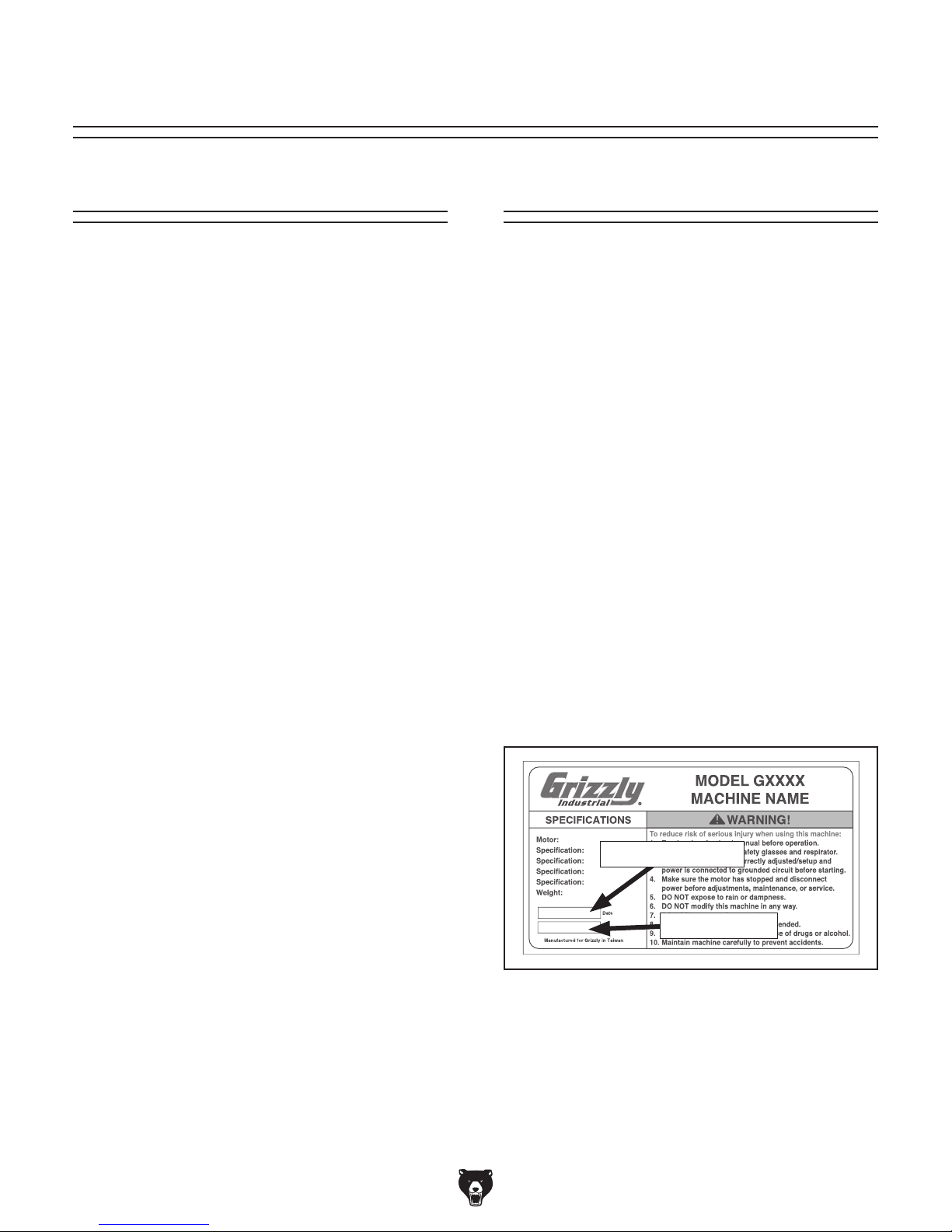
from
the machine ID label (see below). This information
is required for us to provide proper tech support,
and it helps us determine if updated documentation is available for your machine.
INTRODUCTION
Contact Info
and manufacture date from the
Grizzly Technical Support
1815 W. Battlefield
Springfield, MO 65807
Phone: (570) 546-9663
Email: techsupport@grizzly.com
Grizzly Documentation Manager
P.O. Box 2069
Bellingham, WA 98227-2069
Manual Accuracy
made every effort to be exact with the
sometimes the machine
.
,
e post
manual updates for free
www.grizzly.com.
Manufacture Date and Serial Number
Manufacture Date
Serial Number
-2-
Model G0817 (Mfd. Since 05/16)
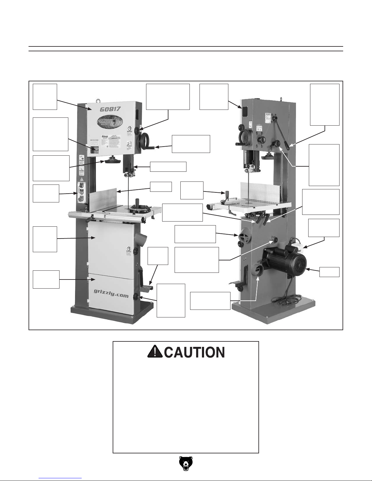
Identification
Become familiar with the names and locations of the controls and features shown below to better understand
the instructions in this manual.
Upper
Wheel
Cover
Blade
Tension
Window &
Scale
Blade
Tension
Handwheel
Control
Panel
Lower
Wheel
Cover
Blade
Storage
Wheel Cover
Lock Knobs
(1 of 2)
Guide Post
Handwheel
Guide Post
Fence
Gauge
Table Tilt
Lock Handle
4" Dust Port
Foot
Brake
Lower Wheel
Adjustment
Blade
Storage
Lock
Knob
Blade
Tracking
Window
Miter
(Upper)
Hub
4" Dust Port
(Lower)
Quick-
Release
Blade
Tension
Lever
Tracking
Control
Knob
w/Lock
Lever
Table Tilt
Adjustment
Handle
Magnetic
Switch
Motor
For Your Own Safety, Read Instruction
Manual Before Operating Saw.
a) Wear eye protection.
b) Do not remove jammed cutoff pieces
c) Maintain proper adjustment of blade
d) Adjust upper guide to just clear
e) Hold workpiece firmly against table.
until blade has stopped.
tension, blade guides, and thrust
bearings.
workpiece.
-3-
Model G0817 (Mfd. Since 05/16)
Controls &
To reduce your risk of
serious injury, read this
entire manual BEFORE
Components
using machine.
Fence & Miter Gauge
D
E
F
Refer to Figures 1–10 and the following descriptions to become familiar with the basic controls
and components of this machine. Understanding
these items and how they work will help you
understand the rest of the manual and stay safe
when operating this machine.
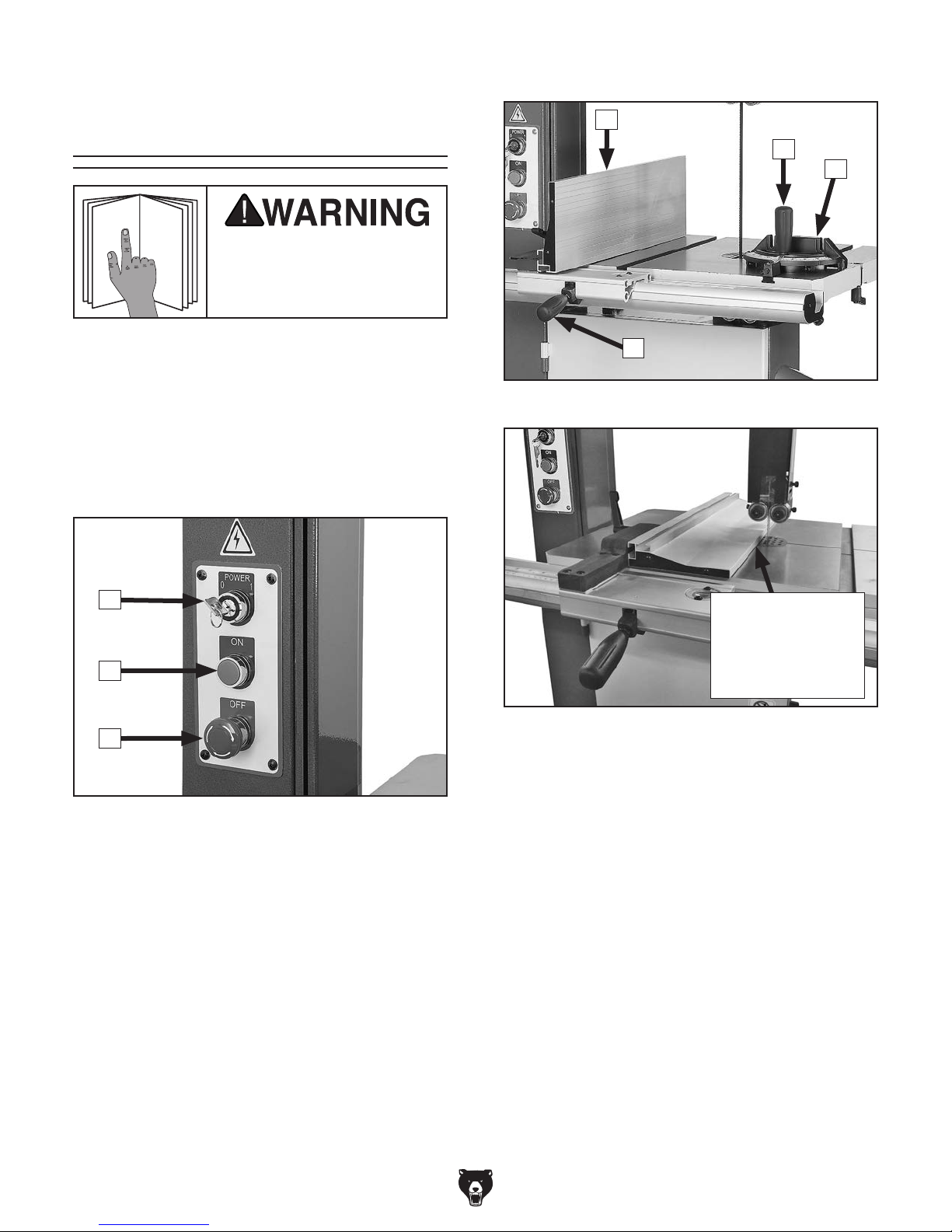
Control Panel
A
B
C
Figure 1. Control panel.
A. Master Power Key Switch: Turns incoming
power ON and OFF. Requires key.
G
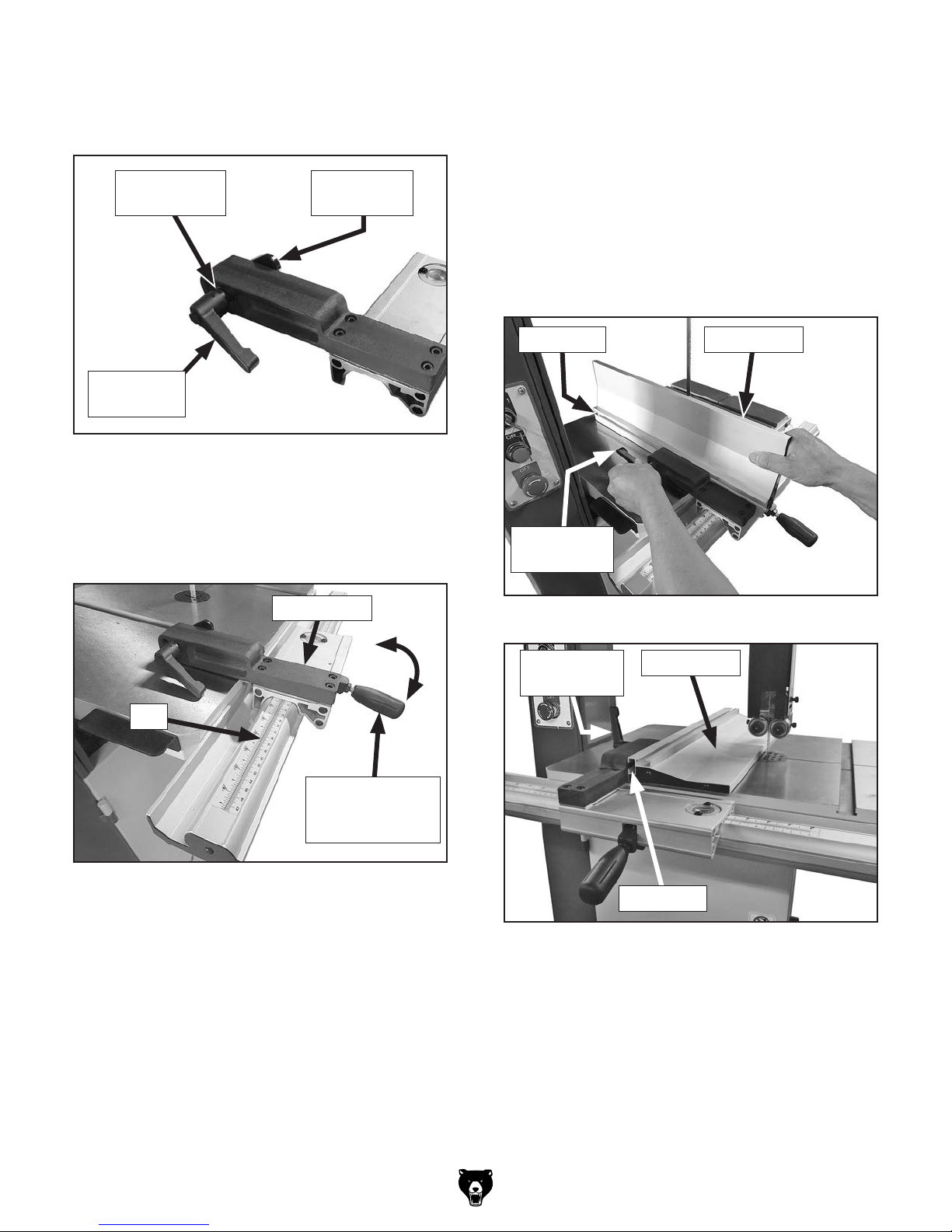
Figure 2. Fence and miter gauge controls.
Horizontal Position
Allows Upper
Blade Guide to Be
Adjusted Closer to
Thin Workpieces
Figure 3. Fence mounted in horizontal position.
D. Fence: Used for ripping o r resawing. Distance
from blade determines width of cut. Can be
used in vertical position (as shown in Figure
2) for normal workpieces, or in horizontal
position (as shown in Figure 3) for thin
workpieces.
B. ON Button: Turns motor ON when pressed.
C. Emergency Stop/Reset Button: Turns
motor OFF when pressed. Motor will not start
until switch is reset. Twist clockwise to reset.
-4-
E. Miter Gauge Lock Knob: Secures angle
position of miter gauge.
F. Miter Gauge: Typically used for cross cuts.
Can be adjusted from 0°–60° left or right, and
has stops at 45°L, 90°, and 45°R.
G. Fence Lock Handle: Secures fence position.
Model G0817 (Mfd. Since 05/16)
Guide Post
Blade Tension & Tracking
K
H
I
J
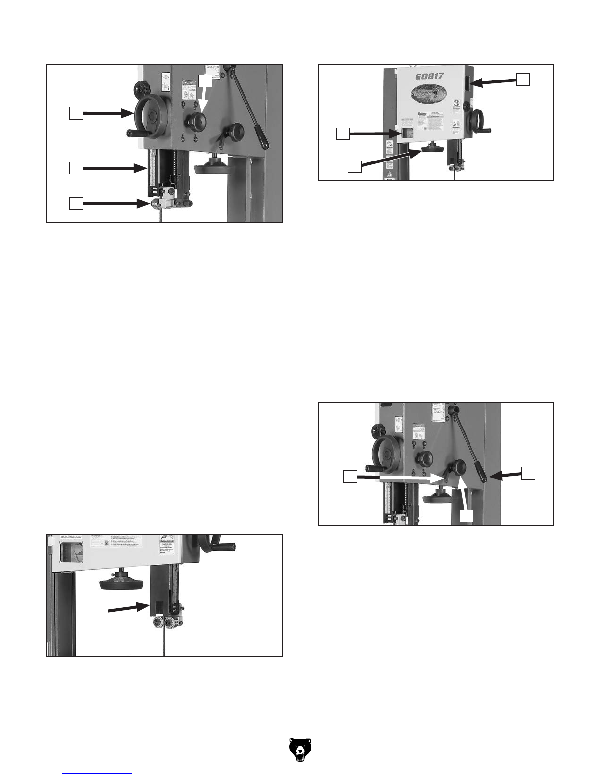
Figure 4. Guide post controls.
H. Guide Post Handwheel: Adjusts height of
guide post above workpiece, using a rackand-pinion system.
I. Guide Post w/Scale: Houses upper blade
guides and support bearing, and shields
operator from upper portion of blade. Adjusts
up or down as necessary to position upper
blade guides/support bearing as close as
possible to workpiece for maximum cutting
accuracy and minimum blade exposure to
operator. Scale on side of guide post indicates height of upper blade guide above
table.
O
M
N
Figure 6. Blade tension handwheel, tension
scale, and tracking window.
M. Blade Tension Scale: Displays blade ten-
sion using numbers 1–8. For reference purposes only—after you have found the proper
tension for the particular blade installed.
N. Blade Tension Handwheel: Increases/
decreases blade tension (refer to Page 28
for more information).
O. Blade Tracking Window: Allows monitoring/
adjustment of blade tracking without requiring
wheel cover to be open (refer to Page 25 for
more information).
J. Upper Blade Guide & Support Bearing:
Support blade above workpiece during operations.
K. Guide Post Lock Knob: Secures guide post
in position after adjustment.
L
Figure 5. Hinge-open blade cover.
L. Hinge-Open Blade Cover: Opens for blade
changes and upper blade guide adjustments
(refer to Pages 31–32).
P
Q
Figure 7. Blade tracking controls and blade
tension quick-release lever.
P. Tracking Control Lock Lever: Secures
position of blade tracking control knob.
Q. Tracking Control Knob: Adjusts tilt position
of upper wheel to set/control blade tracking
(refer to Page 25 for more information).
R. Blade Tension Quick-Release Lever:
Quickly releases blade tension to speed up
blade changes and prevent unnecessary
wear on blade and saw components when
not in use. Move UP to quickly release blade
tension. Move DOWN to re-tension blade.
R
-5-
Model G0817 (Mfd. Since 05/16)
Table Tilt
T
Figure 8. Table tilt controls.
Lower Wheel Adjustment
S
X
U
V
W
S. Table Tilt Indicator: Shows table tilt angle.
T. Table Tilt Lock Lever: Secures table tilt
position on trunnion. Must be loosened before
table tilt can be adjusted.
U. Trunnion w/Table Tilt Scale: Functions as
a tilting base for table. Graduated in degrees
from 5° left–45° right for setting bevel angle.
V. Table Tilt Adjustment Lever: Adjusts angle
of table tilt using a rack-and-pinion system.
W. Positive Stop: Allows for quickly returning
table to a calibrated 0° setting after it has
been tilted to the right (refer to Page 47 for
more information).
Figure 9. Lower wheel adjustment controls.
X. Lower Wheel Adjustment Hub: Adjusts
position of lower wheel to upper wheel if
coplanar adjustments become necessary
(refer to Page 68 for more information).
Note: The wheels are factory-set to be
coplanar, so we strongly recommend that
you avoid making adjustments here unless it
becomes absolutely necessary.
Foot Brake
Y
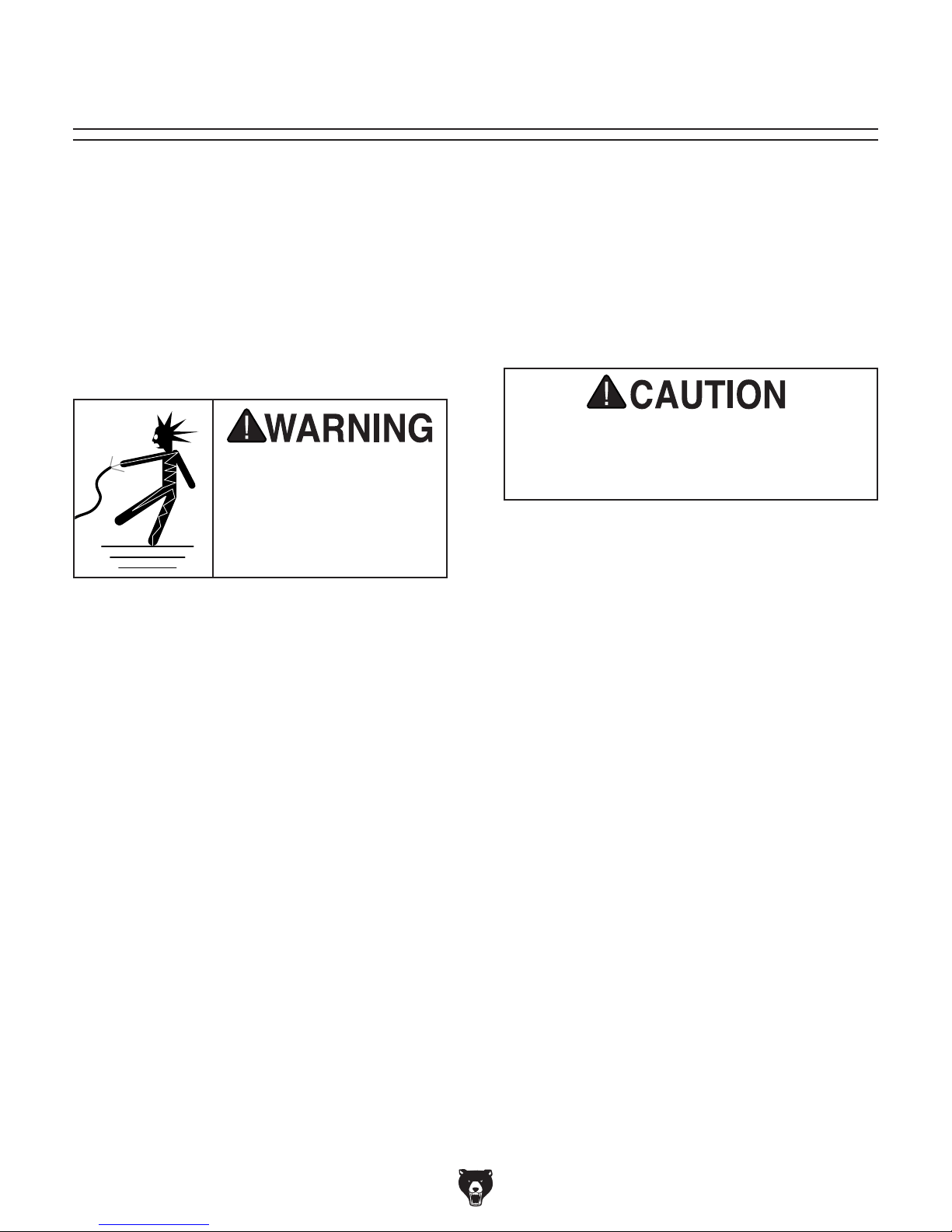
-6-
Figure 10. Location of foot brake.
Y. Foot Brake: Stops blade wheels and turns
motor OFF.
Important: After the foot brake is pressed,
the machine can be restarted by pressing the
ON button. The Emergency Stop button does
not have to be reset.

Model G0817 (Mfd. Since 05/16)
Machine Data Sheet
MACHINE DATA
SHEET
Customer Service #: (570) 546-9663 · To Order Call: (800) 523-4777 · Fax #: (800) 438-5901
MODEL G0817 SUPER HEAVY‐DUTY 14" RESAW BANDSAW
WITH FOOT BRAKE
Product Dimensions:
Weight.............................................................................................................................................................. 319 lbs.
Width (side-to-side) x Depth (front-to-back) x Height..................................................................... 29 x 32-1/2 x 76 in.
Footprint (Length x Width)............................................................................................................................ 24 x 18 in.
Shipping Dimensions:
Type.......................................................................................................................................................... Wood Crate
Content........................................................................................................................................................... Machine
Weight.............................................................................................................................................................. 388 lbs.
Length x Width x Height....................................................................................................................... 30 x 24 x 79 in.
Must Ship Upright................................................................................................................................................... Yes
Electrical:
Power Requirement.............................................................................................. 110V or 220V, Single-Phase, 60Hz
Prewired Voltage.................................................................................................................................................. 110V
Full-Load Current Rating.................................................................................................... 15A at 110V, 7.5A at 220V
Minimum Circuit Size.......................................................................................................... 20A at 110V, 15A at 220V
Connection Type....................................................................................................................................... Cord & Plug
Power Cord Included.............................................................................................................................................. Yes
Power Cord Length................................................................................................................................................. 6 ft.
Power Cord Gauge......................................................................................................................................... 14 AWG
Plug Included.......................................................................................................................................................... Yes
Included Plug Type................................................................................................................................................ 5-15
Recommended Plug Type...................................................................................................................... 6-15 for 220V
Switch Type......................................................................... ON/OFF Push Button Switch w/Emergency Stop Paddle
Motors:
Main
Type................................................................................................................. TEFC Capacitor-Start Induction
Horsepower................................................................................................................................................ 2 HP
Phase............................................................................................................................................ Single-Phase
Amps.................................................................................................................................................... 15A/7.5A
Speed................................................................................................................................................ 1720 RPM
Power Transfer .................................................................................................................................. Belt Drive
Bearings..................................................................................................... Shielded & Permanently Lubricated
Main Specifications:
Main Specifications
Bandsaw Size............................................................................................................................................ 14 in.
Max Cutting Width (Left of Blade)........................................................................................................ 13-1/2 in.
Max Cutting Width (Left of Blade) w/Fence............................................................................................... 12 in.
Max Cutting Height (Resaw Height).......................................................................................................... 14 in.
Blade Speeds..................................................................................................................................... 2820 FPM
-7-

Model G0817 (Mfd. Since 05/16)
Blade Information
Standard Blade Length............................................................................................................................ 120 in.
Blade Width Range............................................................................................................................ 1/8–3/4 in.
Type of Blade Guides........................................................................................................ Dual Roller Bearings
Guide Post Adjustment Type..................................................................................................................... Knob
Has Quick-Release...................................................................................................................................... Yes
Table Information
Table Length........................................................................................................................................ 21-3/4 in.
Table Width......................................................................................................................................... 16-1/8 in.
Table Thickness.................................................................................................................................... 1-1/2 in.
Table Tilt............................................................................................................................ Left 5, Right 45 Deg.
Table Tilt Adjustment Type........................................................................................................................ Lever
Floor-to-Table Height................................................................................................................................. 37 in.
Fence Locking Position.............................................................................................................................. Front
Fence is Adjustable for Blade Lead.............................................................................................................. Yes
Resaw Fence Attachment Included.............................................................................................................. Yes
Miter Gauge Included................................................................................................................................... Yes
Construction Materials
Table.................................................................................................................................................... Cast Iron
Trunnion............................................................................................................................................... Cast Iron
Fence.................................................................................................................................. Extruded Aluminum
Base/Stand...................................................................................................................................... Sheet Metal
Frame/Body..................................................................................................................................... Sheet Metal
Wheels................................................................................................................................................. Cast Iron
Tire................................................................................................................................................ Polyurethane
Wheel Cover ................................................................................................................................... Sheet Metal
Paint Type/Finish........................................................................................................................... Powder Coat
Other Related Information
Wheel Diameter......................................................................................................................................... 14 in.
Wheel Width.......................................................................................................................................... 1-1/8 in.
Number of Dust Ports....................................................................................................................................... 2
Dust Port Size.............................................................................................................................................. 4 in.
Compatible Mobile Base........................................................................................................................ D2057A
Other Specifications:
Country of Origin .............................................................................................................................................. Taiwan
Warranty ........................................................................................................................................................... 1 Year
Approximate Assembly & Setup Time .............................................................................................................. 1 Hour
Serial Number Location ................................................................................................................... Machine ID Label
ISO 9001 Factory .................................................................................................................................................. Yes
Features:
14" Resaw Capacity
2 HP, 110V/220V (Prewired 110V), Single-Phase
Ball-Bearing Blade Guides
Foot-Operated Brake System
Modular Blade-Guide Design for Easy Changeovers Between Styles
Lever-Action Table Trunnion for Quick Table Tilt Adjustment
Cast-Iron Fence with 2-Position Extruded Aluminum Resaw Fence
Storage Area for Extra Blades and Miter Gauge When Not In Use
Cast-Iron Wheels and Table Trunnion
Included Miter Gauge
Blade Tension Indicator
-8-
Model G0817 (Mfd. Since 05/16)
SECTION 1: SAFETY
For Your Own Safety, Read Instruction
Manual Before Operating This Machine
The purpose of safety symbols is to attract your attention to possible hazardous conditions.
This manual uses a series of symbols and signal words intended to convey the level of importance of the safety messages. The progression of symbols is described below. Remember that
safety messages by themselves do not eliminate danger and are not a substitute for proper
accident prevention measures. Always use common sense and good judgment.
Indicates an imminently hazardous situation which, if not avoided,
WILL result in death or serious injury.
Indicates a potentially hazardous situation which, if not avoided,
COULD result in death or serious injury.
Indicates a potentially hazardous situation which, if not avoided,
MAY result in minor or moderate injury. It may also be used to alert
against unsafe practices.
This symbol is used to alert the user to useful information about
NOTICE
proper operation of the machine.
Safety Instructions for Machinery
OWNER’S MANUAL. Read and understand this
owner’s manual BEFORE using machine.
TRAINED OPERATORS ONLY. Untrained operators have a higher risk of being hurt or killed.
Only allow trained/supervised people to use this
machine. When machine is not being used, disconnect power, remove switch keys, or lock-out
machine to prevent unauthorized use—especially
around children. Make workshop kid proof!
DANGEROUS ENVIRONMENTS. Do not use
machinery in areas that are wet, cluttered, or have
poor lighting. Operating machinery in these areas
greatly increases the risk of accidents and injury.
MENTAL ALERTNESS REQUIRED. Full mental
alertness is required for safe operation of machinery. Never operate under the influence of drugs or
alcohol, when tired, or when distracted.
ELECTRICAL EQUIPMENT INJURY RISKS. You
can be shocked, burned, or killed by touching live
electrical components or improperly grounded
machinery. To reduce this risk, only allow qualified
service personnel to do electrical installation or
repair work, and always disconnect power before
accessing or exposing electrical equipment.
DISCONNECT POWER FIRST.
nect machine from power supply BEFORE making
adjustments, changing tooling, or servicing machine.
This prevents an injury risk from unintended startup
or contact with live electrical components.
EYE PROTECTION. Always wear ANSI-approved
safety glasses or a face shield when operating or
observing machinery to reduce the risk of eye
injury or blindness from flying particles. Everyday
eyeglasses are NOT approved safety glasses.
Always discon-
-9-

Model G0817 (Mfd. Since 05/16)
WEARING PROPER APPAREL. Do not wear
clothing, apparel or jewelry that can become
entangled in moving parts. Always tie back or
cover long hair. Wear non-slip footwear to reduce
risk of slipping and losing control or accidentally
contacting cutting tool or moving parts.
HAZARDOUS DUST. Dust created by machinery
operations may cause cancer, birth defects, or
long-term respiratory damage. Be aware of dust
hazards associated with each workpiece material. Always wear a NIOSH-approved respirator to
reduce your risk.
HEARING PROTECTION. Always wear hearing protection when operating or observing loud
machinery. Extended exposure to this noise
without hearing protection can cause permanent
hearing loss.
REMOVE ADJUSTING TOOLS. Tools left on
machinery can become dangerous projectiles
upon startup. Never leave chuck keys, wrenches,
or any other tools on machine. Always verify
removal before starting!
USE CORRECT TOOL FOR THE JOB. Only use
this tool for its intended purpose—do not force
it or an attachment to do a job for which it was
not designed. Never make unapproved modifications—modifying tool or using it differently than
intended may result in malfunction or mechanical
failure that can lead to personal injury or death!
AWKWARD POSITIONS. Keep proper footing
and balance at all times when operating machine.
Do not overreach! Avoid awkward hand positions
that make workpiece control difficult or increase
the risk of accidental injury.
CHILDREN & BYSTANDERS. Keep children and
bystanders at a safe distance from the work area.
Stop using machine if they become a distraction.
GUARDS & COVERS. Guards and covers reduce
accidental contact with moving parts or flying
debris. Make sure they are properly installed,
undamaged, and working correctly BEFORE
operating machine.
FORCING MACHINERY. Do not force machine.
It will do the job safer and better at the rate for
which it was designed.
NEVER STAND ON MACHINE. Serious injury
may occur if machine is tipped or if the cutting
tool is unintentionally contacted.
STABLE MACHINE. Unexpected movement during operation greatly increases risk of injury or
loss of control. Before starting, verify machine is
stable and mobile base (if used) is locked.
USE RECOMMENDED ACCESSORIES. Consult
this owner’s manual or the manufacturer for recommended accessories. Using improper accessories will increase the risk of serious injury.
UNATTENDED OPERATION. To reduce the
risk of accidental injury, turn machine OFF and
ensure all moving parts completely stop before
walking away. Never leave machine running
while unattended.
MAINTAIN WITH CARE. Follow all maintenance
instructions and lubrication schedules to keep
machine in good working condition. A machine
that is improperly maintained could malfunction,
leading to serious personal injury or death.
DAMAGED PARTS. Regularly inspect machine
for damaged, loose, or mis-adjusted parts—or
any condition that could affect safe operation.
Immediately repair/replace BEFORE operating
machine. For your own safety, DO NOT operate
machine with damaged parts!
MAINTAIN POWER CORDS. When disconnecting cord-connected machines from power, grab
and pull the plug—NOT the cord. Pulling the cord
may damage the wires inside. Do not handle
cord/plug with wet hands. Avoid cord damage by
keeping it away from heated surfaces, high traffic
areas, harsh chemicals, and wet/damp locations.
EXPERIENCING DIFFICULTIES. If at any time
you experience difficulties performing the intended operation, stop using the machine! Contact our
Technical Support at (570) 546-9663.
-10 -

Model G0817 (Mfd. Since 05/16)
Additional Safety for Bandsaws
Serious cuts, amputation, or death can occur from contact with the moving saw blade during
operation or if blade breakage occurs. To reduce this risk, anyone operating this machine
MUST completely heed the hazards and warnings below.
HAND PLACEMENT. Placing hands or fingers
in line with blade during operation may result in
serious injury if hands slip or workpiece moves
unexpectedly. Do not position fingers or hands in
line with blade, and never reach under table while
blade is moving.
SMALL/NARROW WORKPIECES. If hands slip
during a cut while holding small workpieces
with fingers, serious personal injury could occur.
Always support/feed small or narrow workpieces
with push sticks, push blocks, jig, vise, or some
type of clamping fixture.
BLADE SPEED. Cutting workpiece before blade
is at full speed could cause blade to grab workpiece and pull hands into blade. Allow blade to
reach full speed before starting cut. DO NOT start
machine with workpiece contacting blade.
FEED RATE. To avoid risk of workpiece slipping
and causing operator injury, always feed stock
evenly and smoothly.
BLADE CONDITION. Dull blades require more
effort to perform cut, increasing risk of accidents.
Do not operate with dir ty, dull, cracked or badly
worn blades. Inspect blades for cracks and missing teeth before each use. Always maintain proper
blade tension and tracking while operating.
CLEARING JAMS AND CUTOFFS. Always stop
bandsaw and disconnect power before clearing
scrap pieces that get stuck between blade and
table insert. Use brush or push stick, not hands,
to clean chips/cutoff scraps from table.
BLADE CONTROL. To avoid risk of injury due to
blade contact, always allow blade to stop on its
own. DO NOT try to stop or slow blade with your
hand or the workpiece.
GUARDS /COVERS. Blade guards and covers
protect operator from the moving bandsaw blade.
The wheel covers protect operator from getting
entangled with rotating wheels or other moving
pa r t s. O N LY operate this bandsaw with blade
guard in proper position and wheel covers completely closed.
BLADE REPLACEMENT. To avoid mishaps that
could result in operator injury, make sure blade
teeth face down toward table and blade is properly tensioned and tracked before operating.
UPPER BLADE GUIDE SUPPORT. To reduce
exposure of operator to blade and provide maximum blade support while cutting, keep upper
blade guides adjusted to just clear workpiece.
CUTTING TECHNIQUES. To avoid blade getting
pulled off wheels or accidentally breaking and
striking operator, always turn bandsaw OFF and
wait for blade to come to a complete stop before
backing workpiece out of blade. DO NOT back
workpiece away from blade while bandsaw is running. DO NOT force or twist blade while cutting,
especially when sawing small curves. This could
result in blade damage or breakage.
WORKPIECE SUPPORT. To maintain maximum
control and reduce risk of blade contact/breakage, always ensure adequate support of long/
large workpieces. Always keep workpiece flat and
firm against table/fence when cutting to avoid loss
of control. If necessary, use a jig or other workholding device.
WORKPIECE MATERIAL. This machine is
intended for cutting natural and man-made wood
products, and laminate covered wood products.
This machine is NOT designed to cut metal,
glass, stone, tile, etc.
-11-
Model G0817 (Mfd. Since 05/16)
SECTION 2: POWER SUPPLY
Before installing the machine, consider the availability and proximity of the required power supply
circuit. If an existing circuit does not meet the
requirements for this machine, a new circuit must
be installed. To minimize the risk of electrocution,
fire, or equipment damage, installation work and
electrical wiring must be done by an electrician or
qualified service personnel in accordance with all
applicable codes and standards.
or equipment damage
may occur if machine is
not properly grounded
and connected to power
The full-load current rating is the amperage a
machine draws at 100% of the rated output power.
On machines with multiple motors, this is the
amperage drawn by the largest motor or sum of all
motors and electrical devices that might operate
at one time during normal operations.
The full-load current is not the maximum amount
of amps that the machine will draw. If the machine
is overloaded, it will draw additional amps beyond
the full-load rating.
If the machine is overloaded for a sufficient length
of time, damage, overheating, or fire may result—
especially if connected to an undersized circuit.
To reduce the risk of these hazards, avoid overloading the machine during operation and make
sure it is connected to a power supply circuit that
meets the specified circuit requirements.
For your own safety and protection of
Note: Circuit requirements in this manual apply to
a dedicated circuit—where only one machine will
be running on the circuit at a time. If machine will
be connected to a shared circuit where multiple
machines may be running at the same time, consult an electrician or qualified service personnel to
ensure circuit is properly sized for safe operation.
A power supply circuit includes all electrical
equipment between the breaker box or fuse panel
in the building and the machine. The power supply circuit used for this machine must be sized to
safely handle the full-load current drawn from the
machine for an extended period of time. (If this
machine is connected to a circuit protected by
fuses, use a time delay fuse marked D.)
This machine can be converted to operate on a
power supply circuit that has a verified ground
and meets the requirements listed below. (Refer
to Voltage Conversion instructions for details.)
This machine is prewired to operate on a power
supply circuit that has a verified ground and meets
the following requirements:
Availability
Electrocution, fire, shock,
supply.
Full-Load Current Rating
Circuit Information
property, consult an electrician if you are
unsure about wiring practices or electrical
codes in your area.
Full-Load Current Rating at 110V ...... 15 Amps
Full-Load Current Rating at 220V .... 7.5 Amps
-12-
Circuit Requirements for 110V
Nominal Voltage .................... 110V, 115V, 120V
Cycle .......................................................... 60 Hz
Phase ........................................... Single-Phase
Power Supply Circuit ......................... 15 Amps
Plug/Receptacle ............................. NEMA 5-15
Circuit Requirements for 220V
Nominal Voltage .........20 8V, 220V, 230V, 24 0V
Cycle .......................................................... 60 Hz
Phase ........................................... Single-Phase
Power Supply Circuit ......................... 15 Amps
Plug/Receptacle ............................. NEMA 6-15
Model G0817 (Mfd. Since 05/16)
Improper connection of the equipment-grounding
wire can result in a risk of electric shock. The
wire with green insulation (with or without yellow
stripes) is the equipment-grounding wire. If repair
or replacement of the power cord or plug is necessary, do not connect the equipment-grounding
wire to a live (current carrying) terminal.
Check with a qualified electrician or service personnel if you do not understand these grounding
requirements, or if you are in doubt about whether
the tool is properly grounded. If you ever notice
that a cord or plug is damaged or worn, disconnect it from power, and immediately replace it with
a new one.
We do not recommend using an extension cord
with this machine.
cord, only use it if absolutely necessary and only
on a temporary basis.
Extension cords cause voltage drop, which can
damage electrical components and shorten motor
life. Voltage drop increases as the extension cord
size gets longer and the gauge size gets smaller
(higher gauge numbers indicate smaller sizes).
Any extension cord used with this machine must
be in good condition and contain a ground wire
and matching plug/receptacle. Additionally, it must
meet the following size requirements:
Grounding Requirements
This machine MUST be grounded. In the event
of certain malfunctions or breakdowns, grounding
reduces the risk of electric shock by providing a
path of least resistance for electric current.
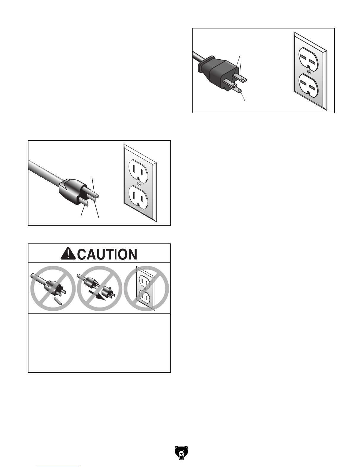
For 110V operation: This machine is equipped
with a power cord that has an equipment-grounding wire and a grounding plug (see following figure). The plug must only be inserted into a matching receptacle (outlet) that is properly installed
and grounded in accordance with all local codes
and ordinances.
For 220V operation: The plug specified under
“
page has a grounding prong that must be attached
to the equipment-grounding wire on the included
power cord. The plug must only be inserted into
a matching receptacle (see following figure) that
is properly installed and grounded in accordance
with all local codes and ordinances.
it will not fit the outlet, have a qualified
GROUNDED
5-15 RECEPTACLE
Grounding Prong
GROUNDED
6-15 RECEPTACLE
Current Carrying Prongs
6-15 PLUG
Grounding Prong
Figure 12. Typical 6-15 plug and receptacle.
5-15 PLUG
Neutral Hot
Figure 11. Typical 5-15 plug and receptacle.
SHOCK HAZARD!
Two-prong outlets do not meet the grounding
requirements for this machine. Do not modify
or use an adapter on the plug provided—if
electrician install the proper outlet with a
verified ground.
Circuit Requirements for 220V” on the previous
Extension Cords
If you must use an extension
Minimum Gauge Size ...........................14 AWG
Maximum Length (Shorter is Better).......50 ft.
-13-
Model G0817 (Mfd. Since 05/16)
MOTOR
220V
START
CAPACITOR
200MFD
250VAC
RUN
CAPACITOR
50MFD
250VAC
Ground
Converting Voltage
MOTOR
110V
START
CAPACITOR
200MFD
250VAC
RUN
CAPACITOR
50MFD
250VAC
Ground
For your own safety and protection of
to 220V
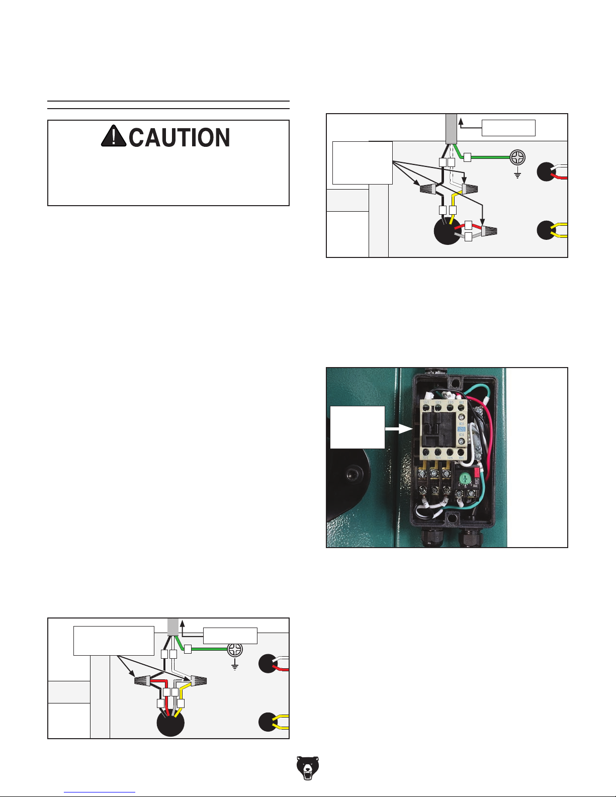
4. Connect wires as indicated in Figure 14.
Secure wire connections with wire nuts, and
wrap them with electrical tape so they will not
vibrate loose during operation.
To Switch
property, consult an electrician if you are
unsure about wiring practices or electrical
codes in your area.
The voltage conversion MUST be performed by
an electrician or qualified service personnel. The
voltage conversion procedure requires purchasing/installing the 220V Conversion Kit (Grizzly
Part # P0817161), rewiring the motor, and installing the correct plug. The necessary wiring diagrams are provided in the Wiring section, beginning on Page 71 for your reference.
IMPORTANT: If the diagram on the motor conflicts with the diagrams in the Wiring section, the
motor may have changed since the manual was
printed. Use the diagram on the motor instead.
Items Needed Qty
• Phillips Head Screwdriver #2 ..................... 1
• Electrical Tap e ............................ As Needed
• Wire Nut (14 AWG x 3) ............................... 1
• Plug 6-15 .................................................... 1
• Wire Cutters/Stripper .................................. 1
Connect
Wires with
E
U
V
Nuts Here
124
3
Figure 14. Motor rewired to 220V.
5. Close and secure motor junction box.
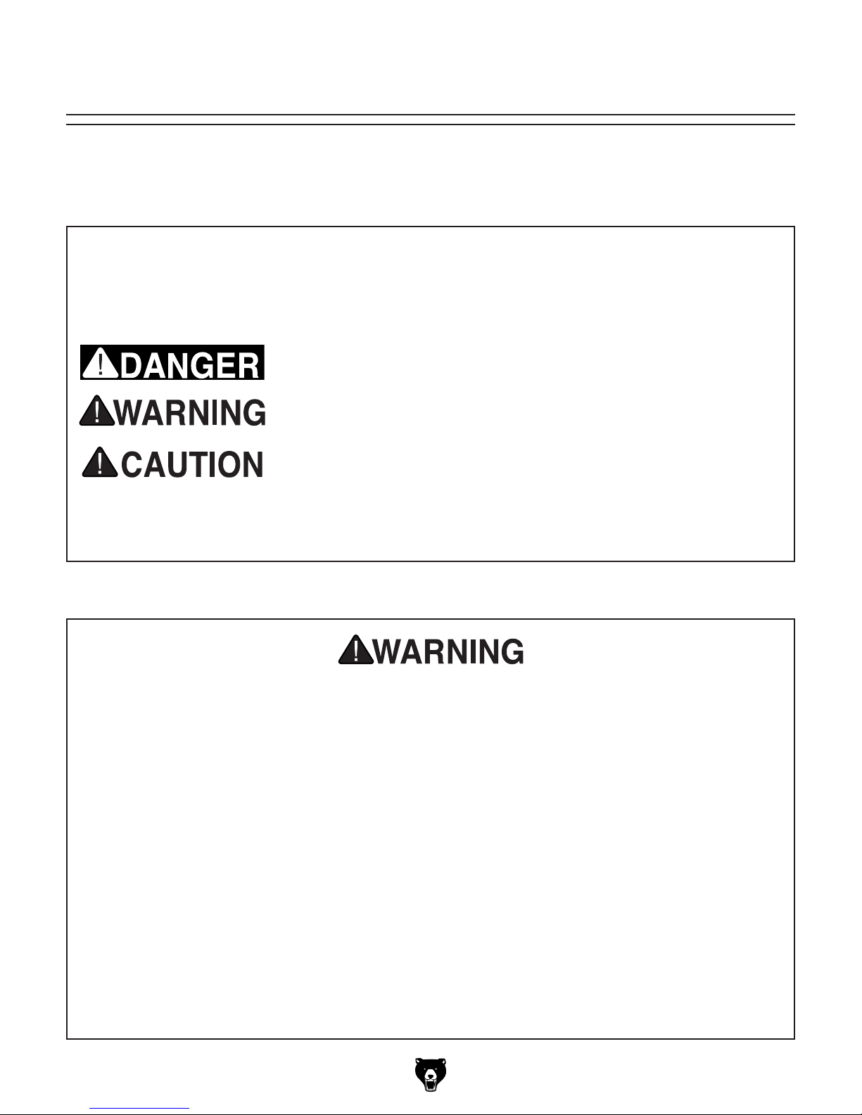
6. Remove 110V magnetic switch assembly
(see Figure 15), and replace it with 220V
conversion kit (Grizzly Part# P0817161).
Magnetic
Switch
Assembly
To convert Model G0817 to 220V:
1. DISCONNECT MACHINE FROM POWER!
2. Cut off existing 5-15 plug.
3. Open motor junction box, then remove two
wire nuts indicated in Figure 13.
Remove These
Wire Nuts
Figure 13. Inside motor junction box.
U
V
3
124
To Switch
E
-14-
Figure 15. Magnetic switch.
7. Install a 6-15 plug on power cord, according
to plug manufacturer's instructions. If plug
manufacturer's instructions are not available,
NEMA standard 6-15 plug wiring is provided
on Page 73.

Model G0817 (Mfd. Since 05/16)
SECTION 3: SETUP
This machine was carefully packaged for safe
transport. When unpacking, separate all enclosed
items from packaging materials and inspect them
for shipping damage.
,
please
IMPORTANT:
you are completely satisfied with the machine and
have resolved any issues between Grizzly or the
shipping agent. You MUST have the original pack-
aging to file a freight claim. It is also extremely
helpful if you need to return your machine later.
Keep children and pets away
from plastic bags or packing
materials shipped with this
The following items are needed, but not included,
for the setup/assembly of this machine.
get help from other people
Needed for Setup
This machine presents
serious injury hazards
to untrained users. Read
through this entire manual to become familiar with
the controls and operations before starting the
machine!
Wear safety glasses during
the entire setup process!
HEAVY LIF T!
Straining or crushing injury
may occur from improperly
lifting machine or some of
its parts. To reduce this risk,
and use a forklift (or other
lifting equipment) rated for
weight of this machine.
Description Qty
• Safety Glasses (for each person) ............... 1
• Solvent/Cleaner .......................................... 1
• Shop Rags .................................................. 1
• Lifting Strap/Chain
(Rated for at least 450 lbs.) ........................ 1
• Lifting Equipment
(Rated for at least 450 lbs.) ........................ 1
• Another Person .......................................... 1
call us immediately at (570) 546-9663.
Unpacking
If items are damaged
Save all packaging materials until
SUFFOCATION HAZARD!
machine. Discard immediately.
-15-
Model G0817 (Mfd. Since 05/16)
Inventory
The following is a list of items shipped with your
machine. Before beginning setup, lay these items
out and inventory them.
If any non-proprietary parts are missing (e.g. a
nut or a washer), we will gladly replace them; or
for the sake of expediency, replacements can be
obtained at your local hardware store.
If you cannot find an item on this list, check
around/inside the machine and packaging materials. Often, these items get lost while unpacking or
they are pre-installed at the factory.
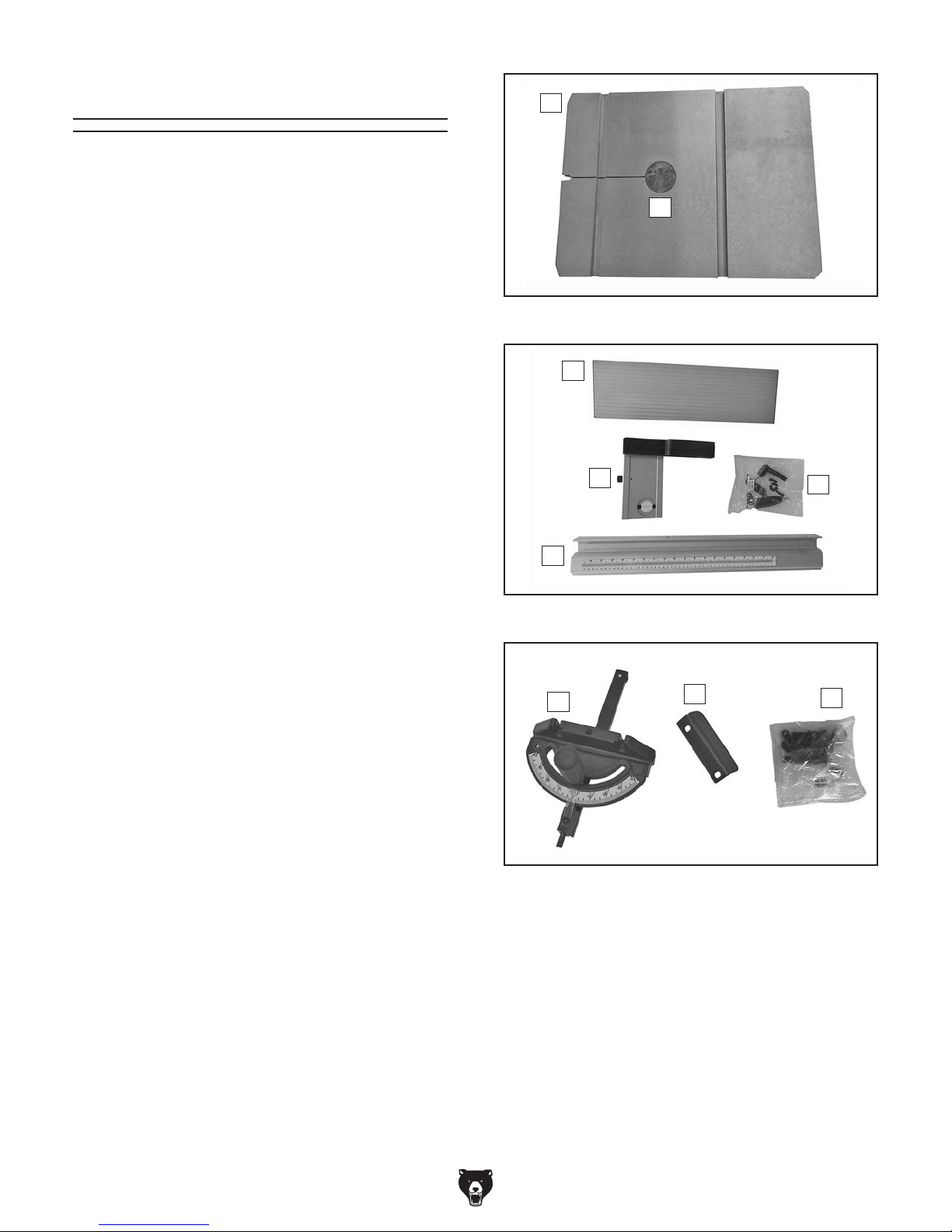
Inventory (Figures 16–18) Qty
A. Main Bandsaw Body (not shown) ............... 1
B. Table ........................................................... 1
C. Table Insert ................................................. 1
D. Fence Face................................................. 1
E. Fence Base Assembly ............................... 1
F. Hardware Bag ............................................ 1
— Hex Bolts M6-1 x 20 ............................... 2
— Lock Washers 6mm ................................ 2
— Flat Washers 6mm .................................. 2
—Fence Face Adjustable Handle .............. 1
— Flat Washer 8mm ................................... 1
— Fence Guide Plate .................................. 1
— Fence Base Lock Lever .......................... 1
— Hex Nut M8-1.25 ..................................... 1
G. Fence Rail .................................................. 1
H. Miter Gauge ................................................ 1
I. Fence Support ............................................ 1
J. Hardware Bag (refer to Page 17) ............... 1
— Lock Washers 8mm ................................ 4
— Flat Washers 8mm .................................. 4
— Hex Bolts M8-1.25 x 25 .......................... 4
— Open-End Wrench 10/13mm .................. 1
— Table Gap Screw Assembly ................... 1
— Hex Nut M8-1.25 ..................................... 1
— Flat Washer 8mm ................................... 1
— Flat Washers 6mm .................................. 2
— Cap Screws M6-1 x 12 ........................... 2
— Hex Wrench 5mm ................................... 1
— Hex Wrench 8mm ................................... 1
B
C
Figure 16. Box 1 inventory.
D
E
G
Figure 17. Box 2 inventory.
H
Figure 18. Loose item inventory.
I
F
J
-16 -
Model G0817 (Mfd. Since 05/16)
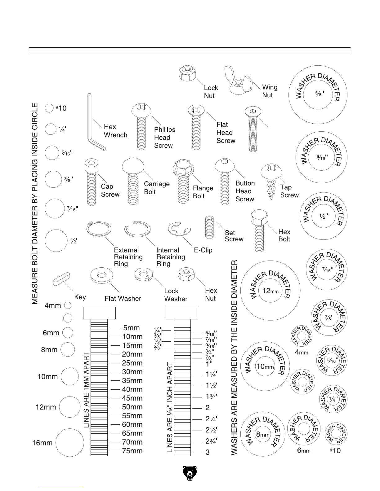
Hardware Recognition Chart
USE THIS CHART TO MATCH UP
HARDWARE DURING THE INVENTORY
AND ASSEMBLY PROCESS.
Flat
Head
Cap
Screw
5mm
5mm
-17-
Model G0817 (Mfd. Since 05/16)
The unpainted surfaces of your machine are
coated with a heavy-duty rust preventative that
prevents corrosion during shipment and storage.
This rust preventative works extremely well, but it
will take a little time to clean.
Be patient and do a thorough job cleaning your
machine. The time you spend doing this now will
give you a better appreciation for the proper care
of your machine's unpainted surfaces.
There are many ways to remove this rust preventative, but the following steps work well in a wide
variety of situations. Always follow the manufacturer’s instructions with any cleaning product you
use and make sure you work in a well-ventilated
area to minimize exposure to toxic fumes.
Before cleaning, gather the following:
• Disposable rags
• Cleaner/degreaser (WD•40 works well)
• Safety glasses & disposable gloves
• Plastic paint scraper (optional)
Basic steps for removing rust preventative:
1.
2.
3.
4.
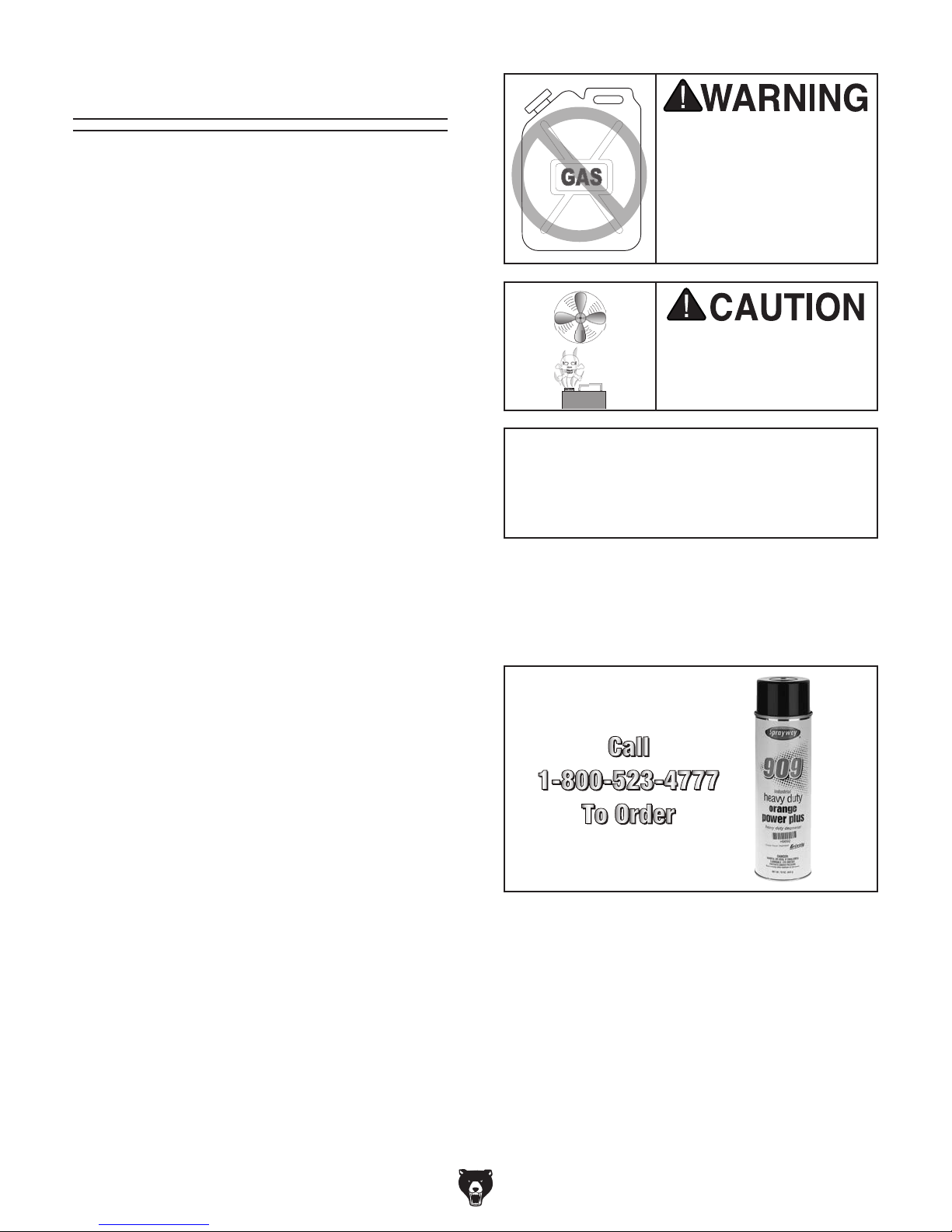
Many cleaning solvents
work in a well-ventilated
Avoid chlorine-based solvents, such as
Cleanup
Gasoline and petroleum
products have low flash
points and can explode
or cause fire if used to
clean machinery. Avo id
using these products
to clean machinery.
Put on safety glasses.
Coat the rust preventative with a liberal
amount of cleaner/degreaser, then let it soak
for 5–10 minutes.
Wipe off the surfaces. If your cleaner/degreas-
er is effective, the rust preventative will wipe
off easily. If you have a plastic paint scraper,
scrape off as much as you can first, then wipe
off the rest with the rag.
Repeat Steps 2–3 as necessary until clean,
then coat all unpainted surfaces with a quality
metal protectant to prevent rust.
are toxic if inhaled. Only
area.
NOTICE
acetone or brake parts cleaner, that may
damage painted surfaces.
T23692—Orange Power Degreaser
A great product for removing the waxy shipping grease from the non-painted parts of the
machine during clean up.
Figure 19. T23692 Orange Power Degreaser.
-18-
Model G0817 (Mfd. Since 05/16)
Site Considerations
Weight Load
Refer to the
of your machine. Make sure that the surface upon
which the machine is placed will bear the weight
of the machine, additional equipment that may be
installed on the machine, and the heaviest workpiece that will be used. Additionally, consider the
weight of the operator and any dynamic loading
that may occur when operating the machine.
Space Allocation
Consider the largest size of workpiece that will
be processed through this machine and provide
enough space around the machine for adequate
operator material handling or the installation of
auxiliary equipment. With permanent installations,
leave enough space around the machine to open
or remove doors/covers as required by the maintenance and service described in this manual.
See below for required space allocation.
Physical Environment
Extreme conditions for this type of machinery are
Place this machine near an existing power source.
other hazards. Make sure to leave enough space
Shadows, glare, or strobe effects that may distract
or impede the operator must be eliminated.
Machine Data Sheet for the weight
Children or untrained people
may be seriously injured by
this machine. Only install in an
access restricted location.
The physical environment where the machine is
operated is important for safe operation and longevity of machine components. For best results,
operate this machine in a dry environment that is
free from excessive moisture, hazardous chemicals, airborne abrasives, or extreme conditions.
generally those where the ambient temperature
range exceeds 41°–104°F; the relative humidity
range exceeds 20%–95% (non-condensing); or
the environment is subject to vibration, shocks,
or bumps.
Electrical Installation
Make sure all power cords are protected from
traffic, material handling, moisture, chemicals, or
around machine to disconnect power supply or
apply a lockout/tagout device, if required.
Lighting
Lighting around the machine must be adequate
enough that operations can be performed safely.
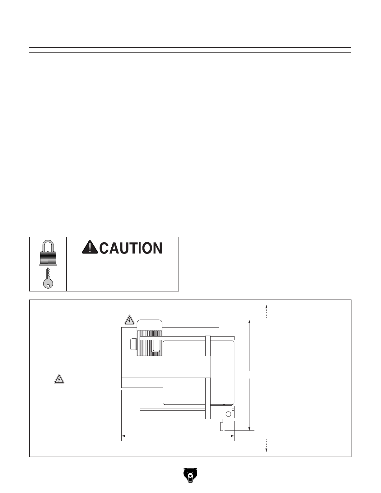
Keep Workpiece
Unloading Area
Unobstructed
= Electrical
Connection
Figure 20. Minimum working clearances.
32½"
28¾"
Keep Workpiece
Loading Area
Unobstructed
-19 -
Model G0817 (Mfd. Since 05/16)
Lifting & Placing
get help from other people
process. DO NOT connect to power until
Using Forklift & Wood Blocks
1. Use forklift to move crate to prepared loca-
tion, then remove crate from shipping pallet.
2. Unbolt bandsaw from pallet.
HEAVY LIF T!
Straining or crushing injury
may occur from improperly
lifting machine or some of
its parts. To reduce this risk,
and use a forklift (or other
lifting equipment) rated for
weight of this machine.
Special care should be taken when moving this
bandsaw. To reduce your risk of injury or accidental damage, use one of the following methods to
lift or move this bandsaw.
Using Forklift & Eye Bolt
1. Use forklift to move crate to prepared loca-
tion, then remove crate from shipping pallet.
2. Unbolt bandsaw from pallet.
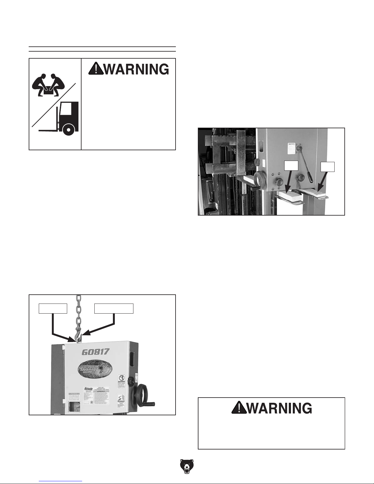
3. Install eye bolt. Make sure it is threaded all
the way in, then place lifting hook through eye
bolt (see Figure 21) and lift bandsaw slowly
with forklift enough to clear pallet.
3. Carefully place forklift forks under bandsaw
head. Insert a 1x4 block between head and
left fork, and a 2x4 block between head and
right fork so bandsaw is level, as shown in
Figure 22.
2x4
Figure 22. Example of lifting bandsaw with
forklift using wood shims.
4. Lift bandsaw off of pallet, remove pallet, then
slowly set bandsaw into position.
Note: If you are concerned about your forklift forks
hitting the tension handwheel, remove handwheel
before positioning forks, then re-install it after
placing bandsaw in final location.
1x4
Eye Bolt Lifting Hook
Figure 21. Lifting bandsaw with eye bolt and
chain.
4. Remove pallet and slowly set bandsaw into
position.
-20-
Using Pallet Jack & Furniture Dolly
1. Use pallet jack to move crate to prepared
location, then remove crate from shipping
pallet.
2. Unbolt bandsaw from pallet.
3. With help of another person, carefully "walk"
bandsaw (or use furniture dolly to move
bandsaw) off of pallet and into position.
Serious injury could occur if you connect
machine to power before completing setup
instructed later in this manual.
Model G0817 (Mfd. Since 05/16)
Anchoring to Floor
Anchoring machinery to the floor prevents tipping
or shifting and reduces vibration that may occur
during operation, resulting in a machine that runs
slightly quieter and feels more solid.
If the machine will be installed in a commercial or
workplace setting, or if it is permanently connected (hardwired) to the power supply, local codes
may require that it be anchored to the floor.
If not required by any local codes, fastening the
machine to the floor is an optional step. If you
choose not to do this with your machine, we recommend placing it on machine mounts, as these
provide an easy method for leveling and they have
vibration-absorbing pads.
Lag shield anchors with lag screws (see below)
are a popular way to anchor machinery to a concrete floor, because the anchors sit flush with the
floor surface, making it easy to unbolt and move
the machine later, if needed. However, anytime
local codes apply, you MUST follow the anchoring
methodology specified by the code.
The machine must be fully assembled before it
can be operated. Before beginning the assembly
process, refer to
and gather
all
goes smoothly, first clean any
ered or coated in heavy-duty rust preventative (if
applicable).
Assembly
Number of Mounting Holes ............................ 4
Diameter of Mounting Hardware .................
3
⁄8"
Anchoring to Concrete Floors
Needed for Setup
listed items. To ensure the assembly process
parts that are cov-
To assemble bandsaw:
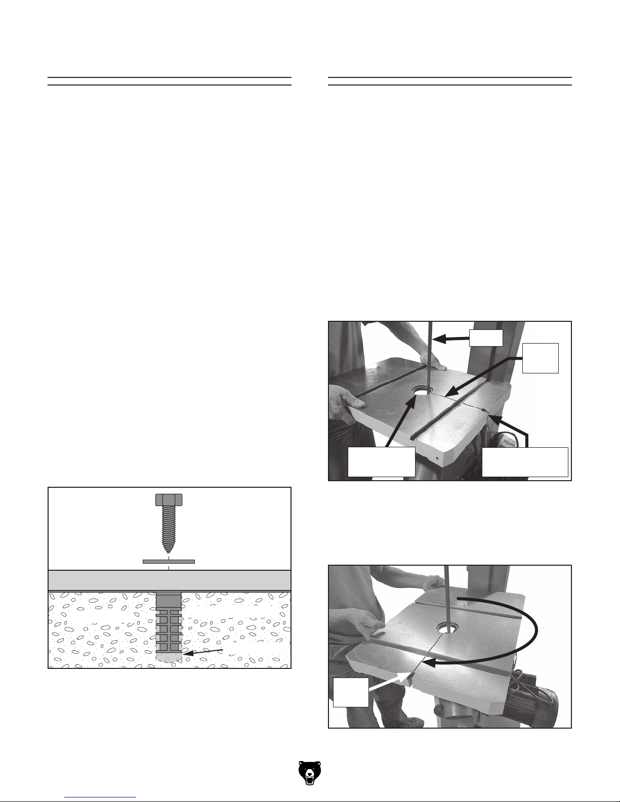
1. Remove protective shipping cover from blade,
then remove table insert and shipping screw
from table (see Figure 24).
2. Place table on saw, sliding table gap around
blade (see Figure 24).
Blade
Table
Gap
Machine Base
Concrete
Figure 23. Popular method for anchoring
machinery to a concrete floor.
Lag Screw
Flat Washer
Lag Shield Anchor
Drilled Hole
Table Insert
Removed
Figure 24. Placing table on saw with gap
positioned around blade.
3. Carefully position table so gap faces to the
right (see Figure 25).
Table
Gap
Figure 25. Table rotated with gap facing to the
right.
Shipping Screw
Removed
-21-
Model G0817 (Mfd. Since 05/16)
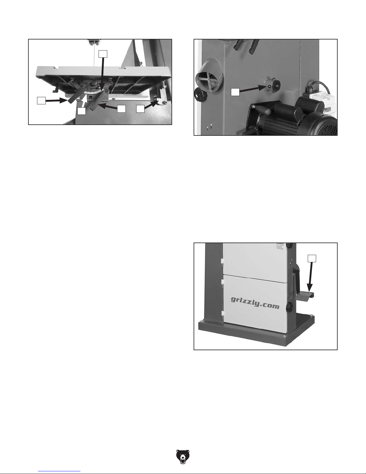
4. Secure table to trunnion using (4) M8-1.25 x
25 hex bolts, (4) 8mm lock washers, and (4)
8mm flat washers (see Figure 26).
x 4
7. Install fence support using (2) M6-1 x 12 cap
screws and 6mm flat washers (see Figure 28).
Fence Support
x 2
Figure 28. Installing fence support.
Figure 26. Table to trunnion mounting hardware
installed.
5. Install table insert (see Figure 27).
6. Install table gap screw assembly, secure with
(1) M8-1.25 hex nut and (1) 8mm flat washer
(see Figure 27), then tighten gap screw to
ensure table surface is flush across gap.
Table Insert
Hex Nut
Gap Screw
and Washer
Assembly
8. Install fence rail using (2) M6-1 x 20 hex
bolts, (2) 6mm lock washers, and (2) 6mm flat
washers (see Figure 29).
x 2
Fence Rail
Figure 29. Installing fence rail.
9. Thread (1) M8-1.25 hex nut onto lock lever,
install lock lever onto fence base, then tighten
hex nut to secure (see Figure 30).
Figure 27. Table insert and gap screw installed.
-22-
Lock
Lever
Fence
Base
Hex Nut
M8-1.25
Figure 30. Fence base lock lever installed.
Model G0817 (Mfd. Since 05/16)
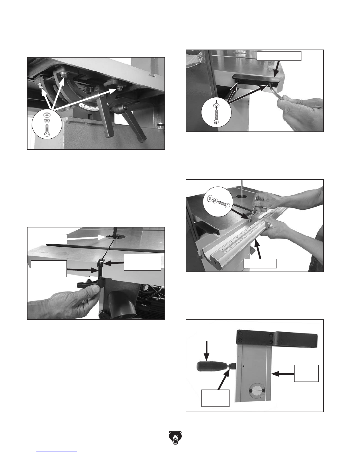
10. Install adjustable handle onto fence base with
(1) 8mm flat washer, and thread into fence
base guide plate (see Figure 31).
Flat Washer
8mm
Fence Base
Guide Plate
Adjustable
Handle
Figure 31. Fence base adjustable handle and
guide plate installed.
11. Place fence base on fence rail with lock lever
raised up. Push lock lever down to secure
fence in place (see Figure 32).
12. Mount fence face to fence base, sliding
T-channel (see Figures 33–34) around fence
base guide plate (see Figure 31).
— For normal workpieces, mount fence in
vertical position, as shown in Figure 33,
then rotate fence base lock lever to secure.
— For thin workpieces, mount fence in hori-
zontal position, as shown in Figure 34,
then rotate fence base lock lever to secure.
Fence FaceT-Channel
Fence Face
Lock Lever
Fence Base
Rail
Lock Lever in
Down (Locked)
Position
Figure 32. Fence base installed on fence rail.
Figure 33. Installing fence in vertical position.
Fence Face
Fence Face
Lock Lever
T-Channel
Figure 34. Fence installed in horizontal position.
-23-
Model G0817 (Mfd. Since 05/16)
Dust Collection
This machine creates substantial amounts
of dust during operation. Breathing airborne dust on a regular basis can result in
permanent respiratory illness. Reduce your
risk by wearing a respirator and capturing
the dust with a dust collection system.
Minimum CFM at each Dust Port: 400 CFM
Do not confuse this CFM recommendation with
the rating of the dust collector. To determine the
CFM at the dust port, you must consider these
variables: (1) CFM rating of the dust collector,
(2) hose type and length between the dust collector and the machine, (3) number of branches
or wyes, and (4) amount of other open lines
throughout the system. Explaining how to calculate these variables is beyond the scope of
this manual. Consult an expert or purchase a
good dust collection "how-to" book.
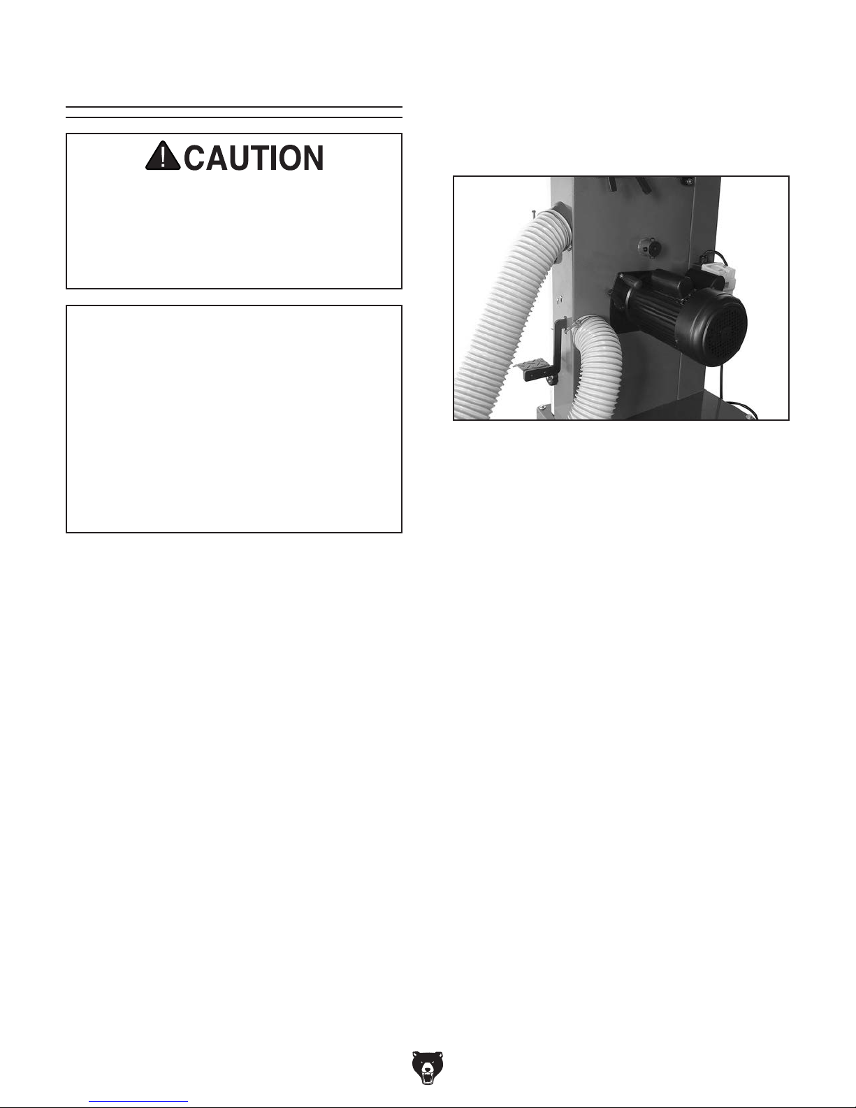
To connect dust collection system to machine:
1. Fit a 4" dust hose over each dust port, and
secure them in place with hose clamps (see
Figure 35).
Figure 35. Dust hoses attached to dust ports.
Note: For best results, connect free ends of
hoses to a 4" Y fitting and secure with hose
clamps, then connect fitting to your dust collection system. See Accessories, beginning
on Page 51, for more information.
2. Tug hoses to make sure they do not come
off.
Note: A tight fit is necessary for proper
performance.
-24-
Model G0817 (Mfd. Since 05/16)
Adjustment
Overview
The bandsaw is one of the most versatile woodworking machines. However, it has multiple components that must be properly adjusted for the
best cutting results.
For practical and safety reasons, some adjustments and test operations must be performed
before performing other necessary adjustments.
Below is an overview of all the adjustments and
the order in which they should be performed:
1. Initial Blade Tracking
2. Test Run
3. Tension Blade
4. Adjusting Blade Support Bearings
5. Adjusting Blade Guide Bearings
6. Table Tilt Calibration
7. Aligning Table
8. Aligning Fence
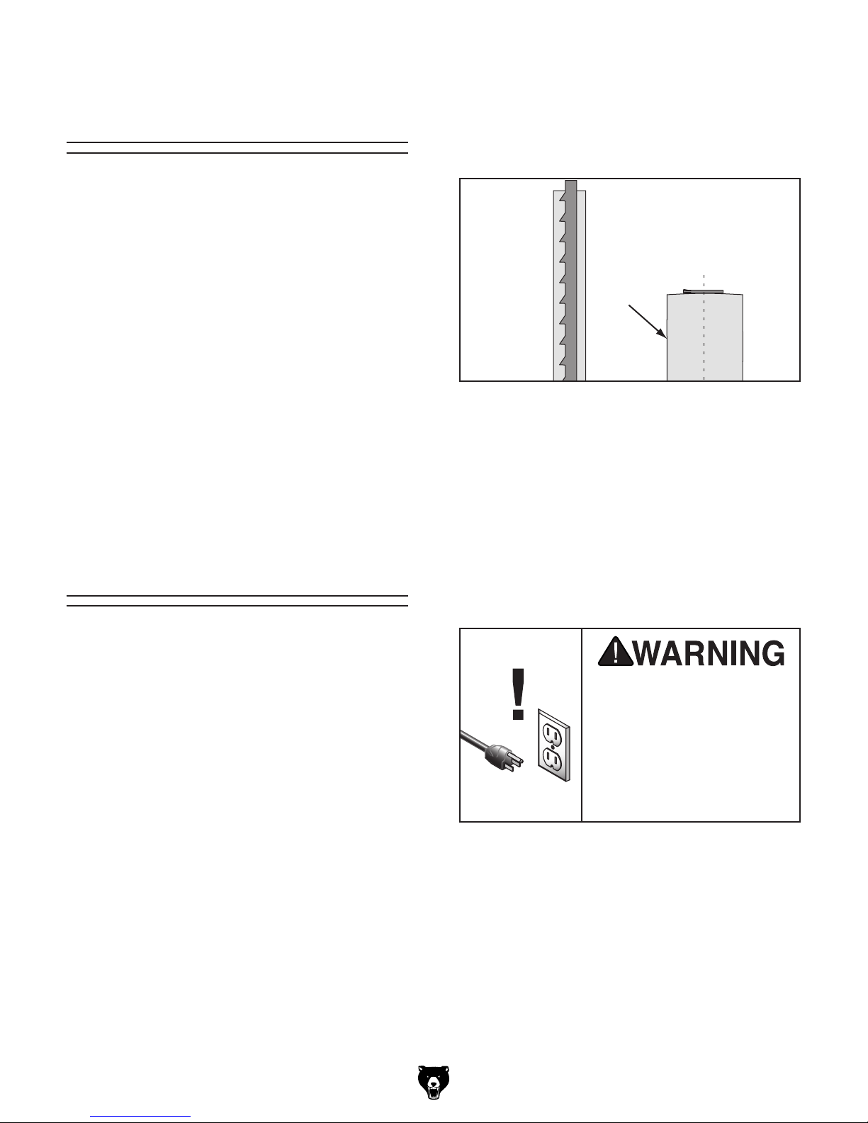
Bandsaw wheels are either flat or crowned and
both shapes track differently. This bandsaw has
crowned wheels. As the wheels spin, a properly
tracking blade naturally tracks at the center of the
wheel (see Figure 36).
PROPER TRACKING
Blade Centered
on Wheel
Blade
Centered
on Wheel
Figure 36. Blade centered on crown of wheel.
Blade tracking is primarily affected by the tilt of
the upper wheel, known as “center tracking.”
However, the alignment of both wheels plays an
important part as well (see Wheel Alignment on
Page 66 for more details).
Wheel
Initial Blade Tracking
"Tracking" refers to how the blade rides on the
bandsaw wheels. Proper tracking is important
for maintaining bandsaw adjustments, achieving correct blade tension, and cutting accurately. Improper tracking reduces cutting accuracy,
causes excess vibrations, and places stress on
the blade and other bandsaw components. The
shape of the wheels and the orientation of the
wheels in relation to each other determine how
the blade tracks.
The wheels on this bandsaw were aligned at the
factory, so center tracking is the only adjustment
that needs to be checked/performed when the
saw is new.
Serious personal injury can
occur if the machine starts
while your hand is touching the bandsaw wheel during tracking adjustments.
Disconnect power from the
bandsaw before performing
blade tracking adjustments.
-25-
 Loading...